JP5225850B2 - Apparatus and method for forming a hole in a luminal organ - Google Patents
Apparatus and method for forming a hole in a luminal organ Download PDFInfo
- Publication number
- JP5225850B2 JP5225850B2 JP2008535748A JP2008535748A JP5225850B2 JP 5225850 B2 JP5225850 B2 JP 5225850B2 JP 2008535748 A JP2008535748 A JP 2008535748A JP 2008535748 A JP2008535748 A JP 2008535748A JP 5225850 B2 JP5225850 B2 JP 5225850B2
- Authority
- JP
- Japan
- Prior art keywords
- cam slot
- sequence
- retractor
- cylinder
- safety latch
- Prior art date
- Legal status (The legal status is an assumption and is not a legal conclusion. Google has not performed a legal analysis and makes no representation as to the accuracy of the status listed.)
- Expired - Fee Related
Links
Images


Classifications
-
- A—HUMAN NECESSITIES
- A61—MEDICAL OR VETERINARY SCIENCE; HYGIENE
- A61B—DIAGNOSIS; SURGERY; IDENTIFICATION
- A61B17/00—Surgical instruments, devices or methods, e.g. tourniquets
- A61B17/32—Surgical cutting instruments
- A61B17/3205—Excision instruments
- A61B17/32053—Punch like cutting instruments, e.g. using a cylindrical or oval knife
-
- A—HUMAN NECESSITIES
- A61—MEDICAL OR VETERINARY SCIENCE; HYGIENE
- A61B—DIAGNOSIS; SURGERY; IDENTIFICATION
- A61B17/00—Surgical instruments, devices or methods, e.g. tourniquets
- A61B17/02—Surgical instruments, devices or methods, e.g. tourniquets for holding wounds open; Tractors
- A61B17/0218—Surgical instruments, devices or methods, e.g. tourniquets for holding wounds open; Tractors for minimally invasive surgery
-
- A—HUMAN NECESSITIES
- A61—MEDICAL OR VETERINARY SCIENCE; HYGIENE
- A61B—DIAGNOSIS; SURGERY; IDENTIFICATION
- A61B17/00—Surgical instruments, devices or methods, e.g. tourniquets
- A61B17/00234—Surgical instruments, devices or methods, e.g. tourniquets for minimally invasive surgery
- A61B2017/00238—Type of minimally invasive operation
- A61B2017/00243—Type of minimally invasive operation cardiac
- A61B2017/00247—Making holes in the wall of the heart, e.g. laser Myocardial revascularization
- A61B2017/00252—Making holes in the wall of the heart, e.g. laser Myocardial revascularization for by-pass connections, i.e. connections from heart chamber to blood vessel or from blood vessel to blood vessel
-
- A—HUMAN NECESSITIES
- A61—MEDICAL OR VETERINARY SCIENCE; HYGIENE
- A61B—DIAGNOSIS; SURGERY; IDENTIFICATION
- A61B17/00—Surgical instruments, devices or methods, e.g. tourniquets
- A61B17/00234—Surgical instruments, devices or methods, e.g. tourniquets for minimally invasive surgery
- A61B2017/00349—Needle-like instruments having hook or barb-like gripping means, e.g. for grasping suture or tissue
-
- A—HUMAN NECESSITIES
- A61—MEDICAL OR VETERINARY SCIENCE; HYGIENE
- A61B—DIAGNOSIS; SURGERY; IDENTIFICATION
- A61B17/00—Surgical instruments, devices or methods, e.g. tourniquets
- A61B2017/00367—Details of actuation of instruments, e.g. relations between pushing buttons, or the like, and activation of the tool, working tip, or the like
- A61B2017/00371—Multiple actuation, e.g. pushing of two buttons, or two working tips becoming operational
- A61B2017/0038—Simultaneous actuation of two tools by pushing one button or the like
-
- A—HUMAN NECESSITIES
- A61—MEDICAL OR VETERINARY SCIENCE; HYGIENE
- A61B—DIAGNOSIS; SURGERY; IDENTIFICATION
- A61B17/00—Surgical instruments, devices or methods, e.g. tourniquets
- A61B2017/00535—Surgical instruments, devices or methods, e.g. tourniquets pneumatically or hydraulically operated
- A61B2017/00557—Surgical instruments, devices or methods, e.g. tourniquets pneumatically or hydraulically operated inflatable
-
- A—HUMAN NECESSITIES
- A61—MEDICAL OR VETERINARY SCIENCE; HYGIENE
- A61B—DIAGNOSIS; SURGERY; IDENTIFICATION
- A61B17/00—Surgical instruments, devices or methods, e.g. tourniquets
- A61B17/02—Surgical instruments, devices or methods, e.g. tourniquets for holding wounds open; Tractors
- A61B2017/0237—Surgical instruments, devices or methods, e.g. tourniquets for holding wounds open; Tractors for heart surgery
-
- A—HUMAN NECESSITIES
- A61—MEDICAL OR VETERINARY SCIENCE; HYGIENE
- A61B—DIAGNOSIS; SURGERY; IDENTIFICATION
- A61B17/00—Surgical instruments, devices or methods, e.g. tourniquets
- A61B17/11—Surgical instruments, devices or methods, e.g. tourniquets for performing anastomosis; Buttons for anastomosis
- A61B2017/1107—Surgical instruments, devices or methods, e.g. tourniquets for performing anastomosis; Buttons for anastomosis for blood vessels
-
- A—HUMAN NECESSITIES
- A61—MEDICAL OR VETERINARY SCIENCE; HYGIENE
- A61B—DIAGNOSIS; SURGERY; IDENTIFICATION
- A61B17/00—Surgical instruments, devices or methods, e.g. tourniquets
- A61B17/11—Surgical instruments, devices or methods, e.g. tourniquets for performing anastomosis; Buttons for anastomosis
- A61B2017/1135—End-to-side connections, e.g. T- or Y-connections
Landscapes
- Health & Medical Sciences (AREA)
- Life Sciences & Earth Sciences (AREA)
- Surgery (AREA)
- General Health & Medical Sciences (AREA)
- Veterinary Medicine (AREA)
- Biomedical Technology (AREA)
- Heart & Thoracic Surgery (AREA)
- Medical Informatics (AREA)
- Molecular Biology (AREA)
- Animal Behavior & Ethology (AREA)
- Nuclear Medicine, Radiotherapy & Molecular Imaging (AREA)
- Public Health (AREA)
- Engineering & Computer Science (AREA)
- Surgical Instruments (AREA)
- Manufacturing Of Micro-Capsules (AREA)
- Dowels (AREA)
- Printers Or Recording Devices Using Electromagnetic And Radiation Means (AREA)
- Cold Cathode And The Manufacture (AREA)
- Control Of Combustion (AREA)
- Coating Apparatus (AREA)
- Lining Or Joining Of Plastics Or The Like (AREA)
Abstract
Description
本発明は、管腔臓器に穴を形成するための器具及び方法に関し、特に心臓に穴を形成するための外科的な器具及び方法に関する。 The present invention relates to instruments and methods for forming holes in luminal organs, and more particularly to surgical instruments and methods for forming holes in the heart.
アメリカの人口の平均年齢が上がるにつれて、大動脈弁狭窄症例も増えていく。従来の外科的な狭窄大動脈弁置換術に対する代替方法としては、大動脈間弁付き導管法(Apicoaortic Conduit)を使用する方法がある。この方法では、生来の心臓弁を取り除かずに並列配置で人工心臓弁が移植される。接続導管(またはチューブ)は下行大動脈に心尖を接続させる。この導管のあるところに人工心臓弁が介在される。このため、血液は心尖を介して心臓から流れ出して、導管(また人工心臓弁)を通って下行大動脈まで移動する。 As the average age of the American population increases, the number of aortic valve stenosis increases. An alternative to conventional surgical stenotic aortic valve replacement is the use of an aortic valve conduit. In this method, prosthetic heart valves are implanted in a side-by-side arrangement without removing the native heart valve. A connecting conduit (or tube) connects the apex to the descending aorta. A prosthetic heart valve is interposed at this conduit. For this reason, blood flows out of the heart via the apex and travels through the conduit (also prosthetic heart valve) to the descending aorta.
最近まで、大動脈間弁付き導管を移植するための外科的手順には、心臓を露出し、下行大動脈が露出するように肺を収縮させるための一つの長い切開、例えば、六番目の肋間を切開する方法が含まれている。大動脈弁置換術に大動脈間弁付き導管をより大規模に用いる可能性を認識するため、何人かの外科医では、現在より小さな切開を用いることが試みられており、最小限の侵襲的手技ができるような手術道具の開発が求められている。この手術をより侵襲的でなくする最初の試みとして、何人かの外科医が近時以下の手順を行った。 Until recently, surgical procedures for implanting an aortic valved conduit include a single long incision to expose the heart and contract the lungs to expose the descending aorta, for example, an incision in the sixth intercostal space A way to be included. To recognize the larger use of inter-aortic valved conduits for aortic valve replacement, some surgeons are now attempting to use smaller incisions and allow minimally invasive procedures The development of such surgical tools is required. As an initial attempt to make this operation less invasive, several surgeons recently performed the following procedures.
患者は仰臥位で手術台にのせられる。麻酔が導入され、二重管腔気管支チューブが患者に挿管されることによって、片肺換気を容易にし、外科医が患者の左胸内部を治療することを許容する。左側が上部(90度)になるように患者は配置される。大腿血管群にアクセスしやすくなるように骨盤は約45度回転される。大腿血管群に横切開が入れられ、総大腿動脈と総大腿静脈が剥離される。次に、ヘパリンが投与される。大腿動脈と大腿静脈内に巾着縫合器が挿入される。まず、動脈にカニューレが挿入され、動脈に針が挿入され、そしてガイドワイヤーが挿入される。このガイドワイヤーが下行大動脈の中にあることを確認するため、経食道心エコーが使用される。この確認をした後、動脈カニューレがガイドワイヤーを越えて動脈内に挿入される(セルジンガー(Seldinger)法)。この動脈カニューレは一般的に19または21フレンチである。挿入された後、巾着縫合器は止血帯の上にぴったりと置かれる。大腿静脈の場合にも同様な手順が行われる。一般的に静脈カニューレは動脈カニューレよりもフレンチが少し大きい。静脈と動脈にもにカニューレされた後、カニューレが心肺バイパスに接合され、いつでも心肺バイパスを開始する準備が完了する。 The patient is placed on the operating table in the supine position. Anesthesia is introduced and a double lumen bronchial tube is intubated into the patient to facilitate single lung ventilation and allow the surgeon to treat the patient's left chest interior. The patient is placed so that the left side is at the top (90 degrees). The pelvis is rotated approximately 45 degrees to facilitate access to the femoral blood vessels. A transverse incision is made in the femoral blood vessel group, and the common femoral artery and the common femoral vein are removed. Next, heparin is administered. A purse string suture device is inserted into the femoral artery and femoral vein. First, a cannula is inserted into the artery, a needle is inserted into the artery, and a guide wire is inserted. Transesophageal echocardiography is used to confirm that this guidewire is in the descending aorta. After this confirmation, the arterial cannula is inserted into the artery over the guide wire (Seldinger method). This arterial cannula is typically 19 or 21 French. After insertion, the purse string suture device is placed snugly over the tourniquet. A similar procedure is performed for the femoral vein. In general, venous cannulas are slightly larger in French than arterial cannulas. After the veins and arteries are also cannulated, the cannula is joined to the cardiopulmonary bypass and is ready to initiate cardiopulmonary bypass at any time.
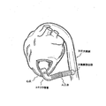
後腋窩線の七番目の肋間で1cm切開されると、ビデオ内視鏡(直径10mm)が挿入され、左胸部の内部が視認される。心尖の位置が確認されると、胸壁に光を透過させるためにビデオ内視鏡からの光を利用することによって、切開の場所を正確に特定できる。そこで、切開が行なわれる。具体的に切開は前開胸切開であって、一般的に6番目の肋間で行なわれる。最近行われている切開は約10cmの長さであるが、経時経過に応じて徐々に小さくなることが予想される。開創器が切開場所に挿入され、創傷は丁寧に開口される。肺開創器は、(収縮した)左肺頭部への移動に使用される。遠位吻合を準備するために下行大動脈は周辺軟部組織から自由に切開される。この切開は、劣った肺間膜の分離が含まれる。綿撤糸縫合は、横隔膜のドーム上に置かれ、横隔膜を足の方向に引っ張るために(邪魔にならないように)配置される。心膜は心尖の周囲で切開され、心尖が開かれて明確に特定される。 When a 1 cm incision is made between the seventh intercostal line of the posterior axilla line, a video endoscope (diameter 10 mm) is inserted, and the inside of the left chest is visually recognized. Once the apex is located, the location of the incision can be accurately identified by utilizing the light from the video endoscope to transmit light through the chest wall. An incision is then made. Specifically, the incision is a pre-thoracotomy and is generally performed in the sixth intercostal space. A recent incision is approximately 10 cm in length, but is expected to gradually decrease with time. A retractor is inserted into the incision site and the wound is carefully opened. The lung retractor is used for movement to the (contracted ) left lung head. To prepare for the distal anastomosis, the descending aorta is freely dissected from the surrounding soft tissue. This incision involves inferior mesenteric separation. A swab suture is placed on the dome of the diaphragm and placed (out of the way) to pull the diaphragm toward the foot. The pericardium is incised around the apex and the apex is opened and clearly identified.
準備台には大動脈間弁付き導管が用意され、例えば、18mm尖端コネクタ(Medtronic:メドトロニック社)に21Freestyleバルブのように大動脈弁の流入開口が縫合されて、20mmHemashildグラフト(移植片)に大動脈弁の流出開口を縫合される。尖端コネクタに関連するダクロン(Dactron)はトロンビンとクリオプレシピテート(寒冷沈降物)で事前に血栓される。このアセンブリは手術台に運ばれ、心尖から下行大動脈までの距離が測定される。この測定距離に合わせてアセンブリは適切に調整される。そして、部分的閉鎖クランプが下行大動脈に固定され、外科用ナイフと鋏を用いて動脈が開口される。導管(20mmHemashildグラフトに縫合される端部)は4−0プロレン縫合糸を用いて繰り返す形で下行大動脈に縫合される。この縫合が完了すると、部分的閉鎖クランプを外して吻合の検査を行う。Freestyle動脈弁の存在によって血液が封じ込められる。尖端コネクタは心尖の上に置かれ、その挿入が計画された位置にマーカーを用いて心尖上の尖端コネクタの円形の輪郭が線引きされる。次に、マーカーで線引きした円を囲む領域が四つに分けられ、2−0プロレン(prolene)縫合糸(刺し縫い(マットレス)縫合糸)の四つの大きい綿撤糸縫合が配置される。そして、縫合糸は尖端コネクタの縫製リングに通される。マーカーで線引きした円の中心部の心尖に刺創を形成し、タンシルクランプを用いて心室に穴をあける。この時点でバイパスを行うことができるが、外科医の中には完全にバイパスを避けるために未完成の手法を開発した者もいた。心室にフォーリー(Foley)カテーテルを挿入し、バルーンを膨らませる。そして、心尖からプラグを切り抜くために穿孔器が使用される。それから、所定の位置に尖端コネクタをパラシュートで投下させる。尖端コネクタを穴に位置合わせするためには回転運動が必要である。次に、四つの綿撤糸縫合が縫合され、止血が検査される。止血に関して懸念があれば追加の縫合糸が配置される。開創器が取り出されて、胸腔チューブが挿入されて、創傷が縫い合わされる。 A conduit with an aortic valve is prepared on the preparation table. For example, an inflow opening of an aortic valve is stitched to an 18 mm tip connector (Medtronic), like a 21 Freestyle valve, and an aortic valve is grafted to a 20 mm Hemaschild graft (graft). The outflow opening is stitched. The Dactron associated with the tip connector is previously thrombus with thrombin and cryoprecipitate. This assembly is taken to the operating table and the distance from the apex to the descending aorta is measured. The assembly is adjusted appropriately for this measurement distance. A partial closure clamp is then secured to the descending aorta and the artery is opened using a surgical knife and scissors. The conduit (the end sutured to the 20 mm Hemaschild graft) is sutured to the descending aorta repeatedly using 4-0 prolene sutures. When this suture is complete, the partial closure clamp is removed and the anastomosis is examined. Blood is contained by the presence of the Freestyle arterial valve. The apex connector is placed on the apex and the circular outline of the apex connector on the apex is delineated using a marker at the location where the insertion is planned. Next, the area surrounding the circle delineated by the marker is divided into four, and four large cotton removal sutures of 2-0 prolene sutures (mattress sutures) are placed. The suture is then passed through the sewing ring of the tip connector. A stab wound is formed at the apex of the center of the circle drawn with a marker, and a hole is made in the ventricle using a tancil clamp. Although bypassing can be done at this point, some surgeons have developed incomplete procedures to avoid bypassing completely. A Foley catheter is inserted into the ventricle and the balloon is inflated. A perforator is then used to cut out the plug from the apex. Then, the tip connector is dropped with a parachute at a predetermined position. A rotational motion is required to align the pointed connector with the hole. Next, four cotton suture sutures are sutured to check for hemostasis. If there are concerns regarding hemostasis, additional sutures are placed. The retractor is removed, the chest tube is inserted, and the wound is stitched together.
大動脈間弁付き導管を移植するために特別に開発された手術器具は、侵襲的手技でない手段を提供することが予想される。この移植手技では、心尖の直上のように、肋間に一連のより小さな開胸術切開部を生じさせることが予想される。鼓動している心臓にその移植手技を実行できるように、適切な手術器具の開発は、胸骨正中切開が避けられるとともに、心肺バイパスの必要性が避けられることが予想される。疾患のある大動脈弁は、露出され、または切除される必要がなくなる。狭窄大動脈弁は留置されて、ある可能なレベルで機能し続けられ、大動脈間弁付き導管は大動脈出力のバランスを調整する。 Surgical instruments specially developed for implanting inter-aortic valved conduits are expected to provide a means that is not an invasive procedure. This transplant procedure is expected to produce a series of smaller thoracotomy incisions between the intercostals, just above the apex. The development of a suitable surgical instrument is expected to avoid the need for cardiopulmonary bypass as well as avoiding median sternum incisions so that the transplant procedure can be performed on the beating heart. A diseased aortic valve does not need to be exposed or removed. The stenotic aortic valve is deployed and continues to function at some possible level, and the interaortic valved conduit balances the aortic output.
この優れた構成の広範な適用に対する主要な障害は、以上説明された移植手技を実行するための効率的な手術器具がほとんどないことである。この移植手技を採用したいという外科医は、様々なメーカーから器具を集める必要がある。しばしば、これらの器具は全く別の用途で製造されているため、外科医は必要に応じて移植手技中に手動でそれらの器具の操作を適応させる必要がある。 A major obstacle to the widespread application of this superior configuration is that there are few efficient surgical instruments to perform the transplant procedures described above. Surgeons who want to adopt this transplantation procedure need to collect instruments from various manufacturers. Often these instruments are manufactured for entirely different applications, and the surgeon needs to manually adapt the operation of these instruments during the implantation procedure as needed.
特許文献1には心尖と下行大動脈の間に大動脈間弁付き導管を移植するための装置が記載されている。心尖にカニューレを挿入するための装置は、組織プラグを切断ることを避けるためにせん孔方法と拡張方法が用いられる。導管を最終位置に設置するために、穴を切り開くには相当な力が必要になる可能性がある。穴を切り開く力は、心臓を大きく変形させて導管の設置を妨げるだけではなく、心臓内構造に害を及ぼす可能性もある。
特許文献2(Nieman)には心臓のような身体部分に遠隔にカニューレを挿入するための提案が記載されている。ここに記載されている器具及び方法は内視鏡的であり、すなわち、器具は長く柔軟な部材の端部に取り付けられ、この器具は、套管針(トロカール:trocar)、すなわち、カニューレを含む鋭く尖った手術道具を通して身体に挿入される。この内視鏡的手術は複雑に見える。外科医または他のコントローラは、器具を心尖または心尖の近くに配置した後、心臓壁にカニューレを固定するために、個別の少なくとも13のステップを実行する。使い勝手の良いインターフェースとともに、これらのステップを調整することはやりがいがある。付着リング(先端リングとロック軸を含む)が心臓壁に縫合され、次に別のステップとしてカニューレが付着リングに接続される。この方法は内視鏡的であるため、閉塞を得るために心室内に正確な深さでバルーンを配置するために画像検査手段(例えば、X線透視検査)が使用される。 Patent Document 2 (Nieman) describes a proposal for remotely cannulating a body part such as the heart. Instruments and methods described herein are endoscopic, i.e., instruments are attach to the ends of the long and flexible member, the instrument is a trocar (trocar: Trocar), i.e., the cannula Inserted into the body through a sharp and pointed surgical tool. This endoscopic surgery looks complicated. The surgeon or other controller performs at least 13 individual steps to secure the cannula to the heart wall after placing the instrument at or near the apex. Coordinating these steps with an easy-to-use interface is challenging. The attachment ring (including the tip ring and lock shaft) is sutured to the heart wall, and then as a separate step the cannula is connected to the attachment ring. Because this method is endoscopic, imaging means (eg, fluoroscopy) are used to place the balloon at the correct depth in the ventricle to obtain occlusion.
Niemanで開示されている複雑な内視鏡的手術は、心臓壁へのカニューレの挿入を進める前に、切り取った組織核(the cut tissue core)を身体から取り除く必要があると思われる。さらに、Niemanは、心臓壁にカニューレを配置するために二つの手段を提供すると思われる。その一つの手段は、カニューレを穴に簡単に挿入できるように十分に大きいな穴を形成すことである。この手段は、心臓壁芯と心室からの失血を防止するために、カニューレと心臓壁芯の間のきつい発作をもたらすものではなく、止血を達成するために縫合された付着リングに完全に依存する。したがって、大量の失血が発生する可能性のある期間をもたらすことになる。第二の手段は、カニューレと穴芯との間のきつい発作(干渉)を達成することである。しかし、このようなきつい発作には、カニューレに強い軸方向の力とねじれ力を加える必要がある。Niemanに記載されている柔軟な内視鏡器具では、このような力がカニューレに伝わらない場合もある。 The complex endoscopic procedure disclosed in Nieman appears to require the cut tissue core to be removed from the body before proceeding with cannulation into the heart wall. In addition, Nieman appears to provide two means for placing a cannula in the heart wall. One means is to make a hole that is large enough to allow easy insertion of the cannula into the hole. This means does not result in a tight seizure between the cannula and the heart wall core to prevent blood loss from the heart wall core and the ventricle, but completely relies on the stitched attachment ring to achieve hemostasis. . Therefore, it will provide a period during which a large amount of blood loss may occur. The second means is to achieve a tight seizure (interference) between the cannula and the hole core. However, such a tight attack requires the application of strong axial and twisting forces to the cannula. In the flexible endoscopic instrument described in Nieman, such forces may not be transmitted to the cannula.
特許文献3(Haverich)には心臓壁に導管を移植する様々な方法が記載されている。図2Aに示すように、巻線付きコークスクリュのあるカッター上に導管が配置されている。カッターが心筋を貫通させるようにコークスクリュが回転される。しかし、心筋をきれいに貫通させるためには強い軸方向の力が必要であるが、コークスクリュによってそのような力を簡単に加えることはできない。さらに、コークスクリュの先端が軸方向の力と回転を加えながら心臓壁の他の領域(例えば、心房)を傷つける可能性もある。Haverichには、止血するために用いられるバルーンが記載されている。しかし、このバルーンはコークスクリュと組み合わせることができない個別の器具である。 U.S. Patent No. 6,057,056 (Haverich) describes various methods of implanting a conduit in the heart wall. As shown in FIG. 2A, a conduit is placed on a cutter with a coiled coke screw. The coke screw is rotated so that the cutter penetrates the myocardium. However, in order to penetrate the myocardium cleanly, a strong axial force is required, but such a force cannot be easily applied by the coke screw. In addition, the tip of the coke screw may damage other areas of the heart wall (eg, the atrium) while applying axial force and rotation. Haveric describes a balloon used to stop hemostasis. However, this balloon is a separate instrument that cannot be combined with a coke screw.
特許文献4(Kaplon)にはHaverichに記載されている装置と同様な装置が記載されているが、臓器壁を貫通させるためにコークスクリュがあるカッターの代わりに套管針(トロカール:trocar)が使用される。套管針では組織プラグが形成されないが、強い力が必要になる場合がある。套管針を使用することにより、鼓動している心臓に移植手技中に止血を達成することは難しい。この問題を解決するために、套管針とともにコネクタが挿入された後、コネクタ16を通して挿入された導管18は挿入場所に縫い付けられて固定される。コネクタ16は心臓壁を貫通しないように見える。コネクタ16には、套管針を取り除いて導管18が挿入されるまで失血を防止するための弁が内蔵されている。 Patent Document 4 (Kaplon) describes a device similar to the device described in Haverich, but instead of a cutter with a coke screw to penetrate the organ wall, a trocar is introduced. used. A trocar does not form a tissue plug, but a strong force may be required. By using a trocar, it is difficult to achieve hemostasis during a transplant procedure on a beating heart. In order to solve this problem, after the connector is inserted together with the trocar, the conduit 18 inserted through the connector 16 is sewn and fixed at the insertion location. The connector 16 does not appear to penetrate the heart wall. Connector 16 incorporates a valve to prevent blood loss until the trocar is removed and conduit 18 is inserted.
特許文献5(Heilman)には、心臓壁に導管を移植するための別の装置が記載され、この装置では空気を排気して失血を防止するための密閉された筐体が利用される。
本発明は、外科医の慎重な行動により安全ラッチが解除されるまでは、管腔臓器の内面を保護するため切断部の切断端部を覆って拡張部を完全拡張状態に維持する安全ラッチ機能を有する管腔臓器壁に穴を形成するためのアプリケータを提供する。 The present invention provides a safety latch function that covers the cut end of the cutting portion and maintains the expansion portion in a fully expanded state to protect the inner surface of the luminal organ until the safety latch is released by the careful action of the surgeon. An applicator for forming a hole in a luminal organ wall is provided.
本発明は、管腔臓器壁に穴を形成するためのアプリケータに関する。前記アプリケータは、管腔臓器壁に穴を形成するための穴形成部と、前記穴形成部が有する遠心端上の切断部と、を含む。前記アプリケータは、前記穴形成部に組み合わせられる前記穴形成部を配置するための配置手段と、前記配置手段と動作的に組み合わせられる開創器と、前記開創器と前記穴形成部との間の相対運動を連続した方法で調整することにより前期管腔臓器壁に穴を形成するための手順を実施するシーケンス手段と、を含む。 The present invention relates to an applicator for forming a hole in a luminal organ wall. The applicator includes a hole forming part for forming a hole in a luminal organ wall, and a cutting part on the distal end of the hole forming part. The applicator includes an arrangement means for arranging the hole forming section to be combined with the hole forming section, a retractor operatively combined with the arrangement means, and between the retractor and the hole forming section. And sequence means for performing a procedure for forming a hole in the luminal organ wall by adjusting relative motion in a continuous manner.
本発明は、管腔臓器壁に穴を形成する方法にも関する。この方法は、穴形成部とともに前記管腔臓器壁に穴を形成するステップと、前記穴形成部が有する遠心端上で切断するステップと、前記穴形成部に組み合わせる配置手段を前記穴形成部に位置決めするステップと、前記配置手段を開創器と動作的に組み合わせるステップと、前記穴形成部に対して前記開創器の相対動作を連続した方法で調整することにより前期管腔臓器壁に穴を形成するための手順を実施するシーケンス手段とステップと、を含む。 The invention also relates to a method of forming a hole in a luminal organ wall. The method includes a step of forming a hole in the luminal organ wall together with a hole forming unit, a step of cutting on a distal end of the hole forming unit, and an arrangement means combined with the hole forming unit in the hole forming unit. Forming a hole in the preluminal organ wall by positioning, operatively combining the positioning means with the retractor, and adjusting the relative movement of the retractor with respect to the hole forming portion in a continuous manner Sequence means and steps for carrying out the procedure for
前記開創器は、前記穴形成部内に移動可能に配置されている開創器本体と、前記開創器本体の遠心端に配置される拡張部と、を備え、前記拡張部は、非拡張状態から完全拡張状態と部分拡張状態まで拡張できてもよい。前記シーケンス手段は、前記拡張部の拡張を連続した方法で非拡張状態から完全拡張状態と部分拡張状態に制御してもよい。また、シーケンス手段は、前記開創器と前記穴形成部と動作的に組み合わせた安全ラッチ部を含んでもよい。さらに、前記シーケンス手段は、前記開創器の中に形成されたシリンダカムスロットを通して伸ばされるシーケンス・ボルトと、押圧部に形成された押圧カムスロットと、前記安全ラッチ部に形成された安全カムスロットと、を含んでもよい。 The retractor includes a retractor body that is movably disposed in the hole forming portion, and an expansion portion that is disposed at a distal end of the retractor body, and the expansion portion is completely unexpanded. It may be possible to expand to an expanded state and a partially expanded state. The sequence means may control the expansion of the expansion unit from a non-expanded state to a fully expanded state and a partially expanded state in a continuous manner. The sequencing means may also include a safety latch portion operatively combined with the retractor and the hole forming portion. Further, the sequence means includes a sequence bolt extended through a cylinder cam slot formed in the retractor, a press cam slot formed in the press portion, and a safety cam slot formed in the safety latch portion. , May be included.
この場合、前記シーケンス手段は、前記複数の部分が順次以下の状態を仮定することを引き起こすための手段を備える。 In this case, the sequence means comprises means for causing the plurality of portions to sequentially assume the following states.
(a)前記シーケンス・ボルトが前記シリンダカムスロットと、前記押圧カムスロットと、前記安全ラッチカムスロットの各々を第1の位置から第2の位置に移動し、前記穴形成部に対して完全伸張位置に前記開創器を保持しながら前記拡張部を完全拡張状態に拡張する第1の状態。 (A) The sequence bolt moves each of the cylinder cam slot, the pressing cam slot, and the safety latch cam slot from the first position to the second position, and is fully extended with respect to the hole forming portion. A first state in which the extension is expanded to a fully expanded state while holding the retractor in position.
(b)前記シーケンス・ボルトが前記シリンダカムスロットと、前記押圧カムスロットと、前記安全カラッチムスロットの各々を前記第2の位置から第3の位置に移動し、前記拡張部を前記完全拡張状態に保持することと前記開創器を前記完全伸張位置に保持する第2の状態。 (B) The sequence bolt moves each of the cylinder cam slot, the pressing cam slot, and the safety calatchum slot from the second position to the third position, and the extended portion is in the fully expanded state. And a second state of holding the retractor in the fully extended position.
(c)前記シーケンス・ボルトが前記シリンダカムスロットと、前記押圧カムスロットと、前記安全ラッチカムスロットの各々を前記第3の位置から第4の位置に移動し、前記拡張部を前記完全拡張位置に保持しながら前記開創器を前記穴形成部の方向に移動させることを可能にする第3の状態。 (C) The sequence bolt moves each of the cylinder cam slot, the pressing cam slot, and the safety latch cam slot from the third position to the fourth position, and the extension portion is moved to the fully extended position. A third state that allows the retractor to be moved in the direction of the hole forming portion while being held in place.
(d)前記シーケンス・ボルトが前記シリンダカムスロットと、前記押圧カムスロットと、前記安全ラッチカムスロットの各々を前記第4の位置に固定し、前記拡張部を前記完全拡張状態に保持する第4の状態。 (D) Fourth that the sequence bolt fixes each of the cylinder cam slot, the pressing cam slot, and the safety latch cam slot in the fourth position, and holds the expanded portion in the fully expanded state. State.
(e)前記シーケンス・ボルトが前記安全ラッチカムスロットを前記第4の位置から第5の位置に再配置し、前記シリンダカムスロットと、前記押圧カムスロットの各々が前記第4の位置に保持されるように、前記開創器に対して前記安全ラッチ部を移動させて、前記拡張部を前記完全拡張状態から解除する第5の状態。 (E) The sequence bolt repositions the safety latch cam slot from the fourth position to the fifth position, and each of the cylinder cam slot and the pressing cam slot is held in the fourth position. A fifth state in which the safety latch portion is moved with respect to the retractor to release the expansion portion from the fully expanded state.
(f)前記シーケンス・ボルトが前記安全ラッチカムスロットを前記第5の位置から第6の位置に移動すると同時に、前記シリンダカムスロットと前記押圧カムスロットの各々を前記第4の位置から前記第5の位置に移動して、前記拡張部を前記部分拡張状態であると仮定する第6の状態。 (F) The sequence bolt moves the safety latch cam slot from the fifth position to the sixth position, and simultaneously moves each of the cylinder cam slot and the pressing cam slot from the fourth position to the fifth position. A sixth state in which it is assumed that the expanded portion is in the partially expanded state.
したがって、本発明は、外科医の慎重な行動により安全ラッチが解除されるまでは、管腔臓器(すなわち、心臓)の内面を保護するため切断部の切断端部を覆って前記拡張部を完全拡張状態(すなわち、第4の状態)に維持する前記安全ラッチを提供する。このように、外科医は心臓の内面を傷つけずに心尖壁にコネクタ導管を配置しながら前記穴形成部を押したり、回転させることができる。 Accordingly, the present invention fully expands the extension over the cut end of the cut to protect the inner surface of the luminal organ (ie, the heart) until the safety latch is released by careful surgeon action. The safety latch is maintained in a state (ie, a fourth state). In this way, the surgeon can push or rotate the hole forming portion while placing the connector conduit in the apex wall without damaging the inner surface of the heart.
また、本発明は、前記シーケンス・ボルトを正確な位置にある前に、外科医が意図的または不注意に解除できない安全ラッチを提供する。さらに、本発明は、前記拡張部が前記穴形成部に少なくとも部分的に配置されるように移動する必要性を緩和させ、リロード中のカム機構が張り付くこと防止する。また、本発明は、心臓壁にコネクタ導管を同時に移植せずに心臓壁に穴をあけるアプリケータを提供する。 The present invention also provides a safety latch that the surgeon cannot intentionally or inadvertently release before the sequence bolt is in the correct position. Furthermore, the present invention alleviates the need to move the extension portion so that it is at least partially disposed in the hole forming portion, and prevents the cam mechanism during reloading from sticking. The present invention also provides an applicator that pierces the heart wall without simultaneously implanting a connector conduit in the heart wall.
本発明は、外科医の慎重な行動により安全ラッチが解除されるまでは、管腔臓器の内面を保護するため切断部の切断端部を覆って拡張部を完全拡張状態に維持する安全ラッチ機能を有する管腔臓器壁に穴を形成するためのアプリケータを提供することができる。 The present invention provides a safety latch function that covers the cut end of the cutting portion and maintains the expansion portion in a fully expanded state to protect the inner surface of the luminal organ until the safety latch is released by the careful action of the surgeon. An applicator for forming a hole in a luminal organ wall can be provided.
図面を参照しながら本発明を詳細に説明する。米国特許出願公開第2005―0251187号(Beane等)に記載されているように、左室心尖の中にコネクタ導管を移植する重要なステップが適切な手順で行われるようにシーケンス部(例えば、カム機構)を使用することが開示されている(図1参照)。組織プラグを作成した上で組織プラグが開創器から滑り落ちることを防止する十分な大きさの直径を残しながら、拡張部が切断部の内径に入ることができるようにシーケンス部は拡張部の直径を部分的に減少させる。 The present invention will be described in detail with reference to the drawings. As described in U.S. Patent Application Publication No. 2005-0251187 (Bane et al.), A sequence portion (e.g., cam (See FIG. 1). In order to allow the extension to enter the inside diameter of the cutting portion while creating the tissue plug, leaving the diameter of the extension to allow the extension to enter the inside diameter of the cutting portion, leaving a diameter large enough to prevent the tissue plug from sliding off the retractor. Partially reduce.
例えば、米国特許出願公開第2005―0251187号は、管腔臓器壁に穴を形成し、この管腔臓器にコネクタ導管を容易に接合するために穴の中にコネクタ導管を挿入するためのアプリケータに関する。アプリケータは、管腔臓器壁に穴を形成するための穴形成部と、穴形成部を配置するために穴形成部と組み合わされる配置手段と、配置手段と動作的に組み合わされる開創器と、管腔臓器壁に穴を形成し、穴にコネクタ導管を挿入するための手順を連続した方法で実行するように穴形成部に対する開創器の相対運動を調整するシーケンス手段と、を含む。 For example, US Patent Application Publication No. 2005-0251187 discloses an applicator for forming a hole in a luminal organ wall and inserting a connector conduit into the hole to facilitate joining the connector conduit to the luminal organ. About. The applicator includes a hole forming portion for forming a hole in the luminal organ wall, a positioning means combined with the hole forming portion to position the hole forming portion, a retractor operatively combined with the positioning means, Sequencing means for adjusting the relative movement of the retractor relative to the hole forming portion so as to perform a procedure for forming a hole in the luminal organ wall and inserting the connector conduit into the hole in a continuous manner.
穴形成部は、管腔臓器壁内にコネクタ導管を移植する手術中に切断部に隣接するコネクタ導管の遠心端で、その穴形成部の遠心端上の切断部と、コネクタ導管と組み合わせるために適応される。開創器は、前記穴形成部内で動作可能に配置され開創器本体と、前記開創器本体の遠心端に配置される拡張可能な拡張部と、を含むことが好ましい。 The hole forming portion is at the distal end of the connector conduit adjacent to the cutting portion during the operation of implanting the connector conduit within the luminal organ wall, to combine the cutting portion on the distal end of the hole forming portion with the connector conduit. Adapted. The retractor preferably includes a retractor body operably disposed within the hole forming portion and an expandable extension disposed at a distal end of the retractor body.
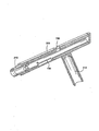
図2A〜図2Cには、図4A〜図4Eに示す米国特許出願公開第2005―0251187号の好ましい実施の形態の構成を示す。この実施の形態は、拡張部530(図2)の拡張に合わせて開創器500の位置を調整するシーケンス部を使用する。この実施の形態では、シーケンス部はカム機構である。カム機構は、コネクタ導管100(図1参照)を移植する際にアプリケータの適切な使用を確実にすることを助ける。図2Bに示すように、開創器500は、開創器アセンブリと称され、その内部に統合されたシリンダ部562を含む。開創器アセンブリは、使用中の押圧部300内に同心円状に配置されている。開創器アセンブリは、その内部に正式なカム機構の部分が含まれ、シリンダ562壁に貫通されたシリンダカムスロット710と、シリンダ562内のピン又はネジ、又は、シリンダ562の一部分にある開創器カム従動子760と、を含む。開創器500は、開創器500が初めて挿入される際にカッター部210が心臓を切ることを防止するため、ストッパーディスク515のように増加した直径の部分を含んでもよい。図2Aは、使用中のシリンダ562内に同心円状に配置されるプランジャ600(以下に説明するようにシーケンス・ボルトの形状である)を示す。プランジャ600は、カム機構の要素が含まれ、プランジャカム従動子750とともにボルト部650が含まれる。プランジャカム従動子750は、シリンダカムスロット710とプッシャ押し込みカムスロット720とともに移動する。プランジャ600は、通路610と注/排弁630(弁本体は表示せず)を含む。注/排弁630は、通路610の内部と外部に液体を流すことを許容するために開けることができる。注/排弁630が閉まっている時は、通路610の内部と外部のどちらの方にも液体を流すことはできない。注/排弁630は、例えば、空気の流路に属する拡張部530、アクセス通路531、他の容積等を液体(生理食塩水等)で満たす前に、これらの容積を排液するために、生理塩水の容器に接続(カテーテルのようなものによって)されてもよい。プランジャ600のO−リング溝620には、液体の漏れを防止するためのO−リング(図示せず)を含む。
2A to 2C show the configuration of a preferred embodiment of US Patent Application Publication No. 2005-0251187 shown in FIGS. 4A to 4E. This embodiment uses a sequence unit that adjusts the position of the
図2Cにおいて、押圧部300と、切断部210と、ハンドル310とを含む堅く結合された部分で構成される位置決めアセンブリを示す。押圧部300には、カム機構の要素として、プッシャ・カムスロット720と、開創器カムスロット730とが含まれる。プッシャ・カムスロット720は、プランジャカム従動子750に合わせて押圧部300の壁に貫通するスロットである。
In FIG. 2C, a positioning assembly is shown that is comprised of a tightly coupled portion that includes a
または、米国特許出願公開第2005―0251187号では、拡張部は拡張していない状態から十分に拡張した状態と、拡張していない状態から部分的に拡張した状態まで拡張してもよいことが記載されている。この場合、シーケンス手段は、前記複数の部分が順次以下の状態を仮定することを引き起こす手段を含んでもよい。第1の状態は、開創器が前記穴形成部に対して完全拡張位置で固定される間、拡張部を拡張させるために、シーケンス・ボルトが第1のスロットとカムスロットの間に移動する状態である。第2の状態は、拡張部を完全拡張状態に保持するためにシーケンス・ボルトが第1のスロットとカムスロットの間に移動する状態である。第3の状態は、シーケンス・ボルトが第1のスロット内に移動し、開創器従動子が開創器を解除するために第2のスロット内に移動し、スプリングが開創器を前記穴形成部に向かって移動することを許可する状態である。第4の状態は、カムスロットが固定されている間にシーケンス・ボルトが第1のスロット内に移動し、穴の形成を完了し、穴内へのコネクタ導管の挿入を許可するために開創器従動子が第2のスロット内に移動する状態である。第5の状態は、拡張部が穴形成部に少なくとも部分的に配置されるように移動する間、拡張部が部分的拡張状態を仮定することを許容し、カムスロットが固定された状態からシーケンス・ボルトを解除するために、シーケンス・ボルトを第1のスロットとカムスロットの間に移動させる状態である。 Alternatively, US Patent Application Publication No. 2005-0251187 describes that the expansion unit may be expanded from an unexpanded state to a fully expanded state and from an unexpanded state to a partially expanded state. Has been. In this case, the sequence means may include means for causing the plurality of parts to sequentially assume the following states. The first condition is that the sequence bolt moves between the first slot and the cam slot to expand the extension while the retractor is secured in the fully extended position relative to the hole forming part. It is. The second state is a state in which the sequence bolt moves between the first slot and the cam slot in order to keep the extension part in the fully extended state. The third condition is that the sequence bolt moves into the first slot, the retractor follower moves into the second slot to release the retractor, and the spring moves the retractor into the hole formation. This is a state in which it is allowed to move toward. The fourth condition is that the retractor follower moves to allow the sequence bolt to move into the first slot while the cam slot is secured, completing the hole formation and inserting the connector conduit into the hole. This is a state in which the child moves into the second slot. The fifth state allows the extension to assume a partially expanded state while the extension moves so as to be at least partially disposed in the hole forming portion, and sequence from the state in which the cam slot is fixed. In order to release the bolt, the sequence bolt is moved between the first slot and the cam slot.
図3A〜図3Cは、米国特許出願公開第2005―0251187号に記載されているカム機構の動作を示す。図3Aは、図2Bのシリンダ562に切り込むシリンダカムスロット710を示す。シリンダカムスロット710は、さらに図3Cに示すように、シリンダ562の外周の周りに角度θ1、θ2及びθ3で三つに相互接続された軸のカムスロットを含む。各角度における軸のカムスロットは、シリンダ562内のプランジャ600の許容される軸方位置の範囲に対応するものである。角度θ1では、カムスロットの軸方向の長さは、シリンダ562内のプランジャ600の最長ストロークに対応する。この最長ストロークは、最小容積から最大容積まで拡張部530を満たすことができる。角度θ2では、軸のカムスロットは最小容積より大きくて最大容積より小さい中間容積まで(中間ストロークで)の容積範囲を拡張部530に与えるために、プランジャ600の動作を許容する。角度θ3では、軸のカムスロットは、拡張部530の最大容積の位置にプランジャ600を保持する。また、図3Aは、動作ステップ中のシリンダカムスロット710内のプランジャカム従動子750の位置A,B,C,D,Eを示す。
3A-3C illustrate the operation of the cam mechanism described in US Patent Application Publication No. 2005-0251187. FIG. 3A shows a
図3Bは、図2Cに示す押圧部の中に切り込んだ押圧カムスロット720と開創器カムスロット730を示す。また、図3Bは、動作ステップ中に、押圧カムスロット720内のプランジャカム従動子750と開創器カムスロット730内の開創器カム従動子760の位置A,B,C,D,Eを示す。図3Cは、シリンダ562と押圧部用の角度θ1〜θ6を示す。説明の目的のため、角度の値はθ1からθ6に増加する。押圧カムスロット720は、シリンダ562の角度θ1とθ3に対応する角度θ1とθ3を含んでもよい(図3A参照)。押圧カムスロット720は、角度θ3よりも大きい角度θ4も含む。押圧カムスロット720の位置Aから位置Bまでの軸方向の長さは、上記説明したように、プランジャ600の最長ストロークに対応する。押圧カムスロット720の位置Cから位置Eまでの軸方向の長さは、中間ストロークと、開創器カム従動子760が開創器カムスロット730内で位置Cから位置Aまで横移動する軸方向の距離との長さに対応する。開創器カムスロット730は、角度θ5とθ6を含む。角度θ5において位置AとBは、押圧部内で圧縮スプリング540がシリンダ562を移動させることを防止する。
FIG. 3B shows the
動作中に、開創器カムスロット730は、押圧部内のシリンダ562の移動を制御する。図3Aと図3Bに示すように、プランジャカム従動子750(シーケンス・ボルト600の)がシリンダカムスロット710内と押圧カムスロット720内で位置Bから位置Cまで円周に移動すると、開創器カム従動子760は開創器カムスロット730内で位置Bから位置Cまで移動させられることによって、圧縮スプリング540が押圧部内で軸方向にシリンダ562を押すことができるようになる。開創器カムスロット730内の開創器カム従動子760は、位置Cから位置Dと位置Eまで移動中の押圧部に対してシリンダ562を一定の角度位置に維持する。したがって、押圧カムスロット720内のプランジャカム従動子750の位置Cから位置Dまでの移動は、シリンダ562の角度θ2に対応する軸方向のスロット内にプランジャカム従動子750を移動させる。
In operation,
図4A〜図4Eを参照して、米国特許出願公開第2005―0251187号のアプリケータの使用中の様々なステップを示す。図4A〜図4Eは、それぞれが図3A〜図3Cで説明した位置Aから位置Eに対応する。個々の外科医が発明を正確に使用するために代替のステップを発見するかもしれないことを認識し、アプリケータを使用してコネクタ導管を移植するための代表的な一連のステップを説明する。心臓壁の組織Tの背後でバルーンを膨らませるために、シーケンス・ボルト600は位置Aから位置Bまで移動される(図4B参照)。外科医はシーケンス・ボルト600を位置Bから位置Cまで(図4C参照)移動してからシーケンス・ボルト650を放す。図4Cの位置Cで始まり、圧縮スプリング540は開創器アセンブリを位置Cから位置Dまで押す(図4D参照)。開創器アセンブリが位置Cから位置Dまで移動すると、心臓壁の組織Tは最初にバルーンと切断部210aの切断端部との間に挟まれる。外科医はハンドル310を用いて、軸方向の力と前進後退回転運動を加えることによって、切断部210の切断端部で心臓壁に穴を開けて切断部210に存在する組織Tのプラグが形成される。位置Dにおいて、開創器アセンブリは、バルーンが切断部210に接触し、組織プラグが切断部210内に完全に入るまで引っ込められる。また、位置Dにおいて、シリンダカムスロット710は、プランジャカム従動子750を円周に角度θ2まで移動させたことによって、バルーンの収縮が開始することを許容する。位置D(図4D)と位置E(図4E)の間でバルーンが中間容積まで収縮すると(上記説明した)、開創器アセンブリは最終位置に収縮する。必要ならば、外科医はシーケンス・ボルト600を最終位置Eまで引いてもよい。
Referring to FIGS. 4A-4E, various steps during use of the applicator of US Patent Application Publication No. 2005-0251187 are shown. 4A to 4E correspond to the positions A to E described with reference to FIGS. 3A to 3C, respectively. Recognizing that an individual surgeon may find alternative steps in order to use the invention correctly, a representative sequence of steps for implanting a connector conduit using an applicator will be described. To inflate the balloon behind the heart wall tissue T, the
心臓の内面(例えば、心室壁、腱索)が損傷することを防止するため、コネクタ導管を心尖壁内の最終位置に完全に挿入して配置するまで、拡張部が十分に拡張した状態(すなわち、図3Bにおける位置Dまたは第4の状態)にとどまることが望ましい。コネクタ導管が第4の状態で部分的に挿入されて、コネクタ導管が最終位置に完全に挿入される前に拡張部が部分拡張した状態になると、心尖壁内の最終位置にコネクタ導管を配置するためにねじったり押したりする動作をしている間、穴形成部の切断部が心臓の内面(例えば、心内膜、腱索)に露出する恐れがあり、心臓の内面を損傷する結果になる。このように、コネクタ導管が最終位置に操作される際に、十分に拡張した拡張部が穴形成部の切断部を覆うことによって心臓の内面が損傷することを防止することになる。 To prevent damage to the inner surface of the heart (e.g., ventricular wall, chordae), the dilator is fully expanded (i.e., until the connector conduit is fully inserted and positioned in the final position within the apical wall). It is desirable to remain in position D or the fourth state in FIG. 3B. When the connector conduit is partially inserted in the fourth state and the extension is in a partially expanded state before the connector conduit is fully inserted into the final position, the connector conduit is placed in the final position within the apex wall. During the operation of twisting and pushing, the cut part of the hole forming part may be exposed to the inner surface of the heart (for example, endocardium, chordae), resulting in damage to the inner surface of the heart . In this way, when the connector conduit is manipulated to the final position, the fully expanded extension will prevent the inner surface of the heart from being damaged by covering the cut of the hole forming portion.
これにより、本発明は外科医の意図的な行動により安全ラッチが解除されるまで、上述の第4の状態から第5の状態に進むことを防止する安全ラッチを提供して上述のアプリケータを改良することにより、心臓の内面が損傷する可能性を削減する。このように、拡張部が部分拡張状態になることを許可するために、外科医が意図的に安全ラッチを解除する前に心尖壁内の最終位置にコネクタ導管を配置することができる。 Thus, the present invention improves the applicator by providing a safety latch that prevents the fourth state from going to the fifth state until the safety latch is released by the surgeon's intentional action. By doing so, the possibility of damaging the inner surface of the heart is reduced. In this way, the connector conduit can be placed in a final position within the apical wall before the surgeon intentionally releases the safety latch to allow the expansion portion to enter a partially expanded state.
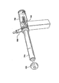
図5は本発明に係る概略的なアプリケータと安全ラッチの分解図を示す。図5に示す基本的構成と参照符号は、米国特許出願公開第2005―0251187号において説明される基本的構成と参照符号と同一である。例えば、図5に示すアプリケータは、ハンドル310と、拡張部530と、ストッパーディスク515と、切断部210と、ボルト部650(例えば、シーケンス・ボルト)と、押圧部300と、を含む。また、押圧部300は押圧カムスロット720と押圧ラッチカムスロット741を含む。図5は、さらに本発明に係る安全ラッチを含む。本発明に係る安全ラッチは、ラッチシリンダ780を含む。ラッチシリンダ780は、安全ラッチカムスロット740と、レバー781と、溝付き面782と、スプリング部(図示せず)と、を含む。
FIG. 5 shows an exploded view of a schematic applicator and safety latch according to the present invention. The basic configuration and reference numerals shown in FIG. 5 are the same as the basic configuration and reference numerals described in US Patent Application Publication No. 2005-0251187. For example, the applicator shown in FIG. 5 includes a
作動中、ラッチシリンダ780は、通常は安全ラッチカムスロット740が押圧カムスロット720の上部に配置されるように、押圧部300の上部に同心円状に配置される。この構成では、シーケンス・ボルト650は、押圧カムスロット720と安全ラッチカムスロット740の双方を通して伸ばされる。また、ラッチシリンダ780が押圧部300の上部に配置されると、スプリング部(図示せず)は押圧部300内に配置され、スプリング部は押圧部に対してラッチシリンダ780を回転させながら付勢する。
In operation, the
安全ラッチ部は、さらに安全ラッチカム従動子770を含む。この安全ラッチカム従動子770は、例えば、レバー781にぴったりとフィットし、ラッチシリンダ780を通って押圧ラッチカムスロット741内に伸びるネジピンである。したがって、ラッチシリンダ780が押圧部300に対して回転されると、安全ラッチカム従動子770の先端は押圧ラッチカムスロット741内に移動される。また、さらに任意のカムスロット(例えば、開創器ラッチスロット742)があり、このカムスロットは押圧部300内に同心円状に配置された開創器部内に配置されてもよい(図6A参照)。本発明に係る最良の形態によれば、安全ラッチカム従動子770の先端が押圧ラッチカムスロット741を通って開創器ラッチスロット742内にさらに伸ばされることにより、押圧部300と開創器部の双方(逆もまた同様に)に関係するラッチシリンダ780の回転運動を制限する。したがって、安全ラッチカム従動子770は、押圧ラッチカムスロット741と開創器ラッチスロット742ともに、限定的な回転運動のみを許可するため、押圧部300と開創器部に対してラッチシリンダ780の移動を制限する。この回転運動はレバー781と溝付き面782により容易になる。
The safety latch portion further includes a safety
図3と図4は、米国特許出願公開第2005―0251187号に開示されるように、開創器アセンブリ(図3A)と押圧部(図3B)内のスロットの方向性と相対的位置を示す。それらのスロット群は、動作中、図3Bのスロット群が図3Aのスロット群の上に重ね合わされるように図示される。これらの図は、シーケンス・ボルト650が開創器アセンブリのシリンダカムスロット710と同時に押圧アセンブリの押圧カムスロット720を通して移動される時に、開創器部と押圧部の相対運動をさらに示す。(シーケンス・ボルト650の)プランジャカム従動子750が押圧カムスロット720の位置Cに移動されると、圧縮スプリング540が押圧部内で軸方向に位置Cから位置Eまで軸方向にシリンダ562を押圧する(図4参照)。
3 and 4 show the orientation and relative position of the retractor assembly (FIG. 3A) and the slot in the pusher (FIG. 3B), as disclosed in US Patent Application Publication No. 2005-0251187. The slots are illustrated such that, in operation, the slots of FIG. 3B are superimposed on the slots of FIG. 3A. These figures further illustrate the relative movement of the retractor portion and the pusher when the
また、図3と図4に関して、シーケンス・ボルト650が位置Cから位置Eに移動することが完了すると、ユーザーがカム機構の移動子を位置Eから位置Cに逆進させることにより装置をリロードしたい場合がある。位置Eから位置Cに移動中にシーケンス・ボルト650に加えられた力は、拡張部530を完全に膨らませ、圧縮スプリング540を圧縮させる。リロード中に位置Dに達すと、拡張部530を膨らませるためにシーケンス・ボルト650に加えられた力が圧縮スプリング540を圧縮するのに必要な力を超えていれば、シリンダ562は押圧部300に対して移動できることになり、カムスロットの位置がずれて、カムスロットにおいてシーケンス・ボルト650の望まれていない結合をもたらす。位置Dに停止するように開創器カムスロット730の長さを減少させて、開創器500の移動を制限することにより、この結合は回避できる(図3B参照)。その結果、拡張部530は切断部210内に完全に後退しない。図6Bは、上記説明したように短くされた典型的な開創器カムスロット730を示す。図6Bに明示するように、開創器カムスロット730において位置D,E,Fは全て同じ位置にある。
3 and 4, once the
図3と図4の参照に戻り、プランジャカム従動子750が位置Dを通過する際に、臓器に穴が形成され、拡張部の拡張状態は完全拡張状態から部分拡張状態に変更される。この場合、臓器壁に穴を完全に開く前に拡張部が部分拡張態になることが可能である。また、外科医は穴を開けてコネクタ導管を配置するためにアプリケータをねじったり押したりしている間、拡張部の部分拡張状態に早期に収縮させることは管腔臓器の内面(例えば、心内膜、腱索)に穴形成部の切断部を露出させる結果になる場合がある。この露出は、臓器の内面を傷付けることになり、患者に負傷または死をもたらす可能性がある。
3 and 4, when the
これに対して、本発明は管腔臓器の内面に切断部を露出することを防止する安全ラッチ部を提供する。特に、開創器アセンブリ(図6A)と、押圧部(図6B)と、安全ラッチ部(図6C)において、本発明のスロットの平面配向と相対位置を図6A〜図6Dに示すように、本発明はシーケンス・ボルト650の移動を位置Dに停止する安全ラッチカムスロットを特徴とする安全ラッチを含み、外科医の意図的な行動により安全ラッチが解除されるまで位置Dに進むことを防止する。この特徴は、位置Dで安全カムスロットにより実現され、図6Cに示す安全ラッチカムスロット740のコーナー部分に位置する。以上述べたように、安全ラッチ部には、押圧アセンブリに対して安全ラッチを回転的に付勢する内部スプリング部が含まれる。この構成では、スプリングは安全ラッチアセンブリを図6Cにおいて下向きに回転的に付勢することにより、安全ラッチカムスロットの位置Dにシーケンス・ボルトを付勢し、位置Eの押圧アセンブリに対する安全ラッチカムスロットの不注意な回転を防止する。
In contrast, the present invention provides a safety latch portion that prevents the cut portion from being exposed on the inner surface of the luminal organ. In particular, in the retractor assembly (FIG. 6A), the pressing portion (FIG. 6B), and the safety latch portion (FIG. 6C), the planar orientation and relative position of the slot of the present invention are as shown in FIGS. The invention includes a safety latch featuring a safety latch cam slot that stops movement of the
図6Aは、シリンダ562の平面図(例えば、開創器アセンブリ)であり、シリンダ562上のシリンダカムスロット710と開創器ラッチカムスロット742の位置を示す。また、図6Aはシリンダ562に堅く結合された開創器カム従動子760の位置を示す。作動中、ラッチ781(図5)と押圧ラッチカムスロット741(図6B)を通って挿入される安全ラッチカム従動子770は、拡張部530が切断部210の切断端部に近づくため、任意の開創器ラッチスロット742の中に入る。押圧部300に対して軸方向にシリンダ562と開創器アセンブリとを動作的にロックするように、開創器ラッチスロット742の位置Dから位置Eに安全ラッチカム従動子770を移動するためにラッチシリンダ780を回転させることができる。この軸方向にロックすることは、アプリケータを再使用すめたにリロードするときのように、シーケンス・ボルト650が位置Fから位置Cに移動する際に、押圧部300内でのシリンダ562の移動を制限する。カムスロット内でのシーケンス・ボルト650の望まれていない結合を防止する手段として、任意の開創器ラッチスロット742が短くされた開創器カムスロット730と共に、または代わりに利用できることに、注目すべきである。
FIG. 6A is a plan view of cylinder 562 (eg, retractor assembly) showing the position of
同様に、図6Bは、押圧部300の平面図である。押圧部300は、開創器カムスロット730と、押圧カムスロット720と、押圧ラッチカムスロット741の三つのスロットを含むことが望ましい。本発明に係る上記説明した開創器カムスロット730は、切断部の切断端面との接触に拡張部を運ぶために適した長さであるが、望ましくは、アプリケータを抜き取る前に拡張部を穴形成部に引き下がらせるのに十分な長さではない。上記説明したように、安全ラッチカム従動子770は押圧ラッチカムスロット741の中に配置されている。したがって、安全ラッチカム従動子770は押圧ラッチカムスロット741の制限内で移動できる。図6Bに示すように、安全ラッチカム従動子770は押圧ラッチカムスロット741の制限内で回転できる。また、開創器アセンブリに対して押圧アセンブリの相対位置は、開創器カム従動子760と開創器カムスロット730との相互作用によって制御される。押圧カムスロット720は、アプリケータ内の構成要素の移動を制御するための押圧部300の主要なスロットである。安全ラッチカムスロット740とシリンダカムスロット710内を通る(シーケンス・ボルト650の)プランジャカム従動子750は押圧カムスロット720の中に配置される。
Similarly, FIG. 6B is a plan view of the
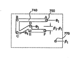
図6Cは本発明に係る安全ラッチ部(ラッチシリンダ780を含む)の平面図である。ラッチシリンダ780は、安全ラッチカムスロット740とラッチ781とを含み、プランジャカム従動子750は安全ラッチカムスロット740内を通り、安全ラッチカム従動子770がレバー781内を通る。安全ラッチカム従動子770は、ラッチシリンダ780と堅く結合されるのが望ましい。また、安全ラッチカムスロット740の部分が安全ラッチ部の機能とシーケンス・ボルトの移動を妨げない限り、完全に閉鎖されなくてもよいことに注意すべきである。
FIG. 6C is a plan view of the safety latch portion (including the latch cylinder 780) according to the present invention. The
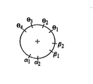
図6Dは、シリンダ562と押圧部300とラッチシリンダ780の各回転角度θ1〜θ4、α1〜α2、β1〜β2を示す。また、位置A,B,C,D,E,Fはカムスロット内のプランジャカム従動子750と、開創器カム従動子760と、安全ラッチカム従動子770の位置を示す。これらの位置がそれぞれ状態位置を表す。図6A〜図6Dに示すデザインにおいて、シーケンス・ボルト650が位置Cから位置Dに移動する時だけ、シリンダ562は押圧部300に対して軸方向に移動する。相対移動の範囲は、位置Cと位置Dとの間の開創器カムスロット730の長さにより定義される。シーケンス・ボルト650が位置Eから位置Fに移動する時、拡張部530が部分拡張状態になる間にシリンダ562は軸方向に移動しない。
6D shows the rotation angles θ1 to θ4, α1 to α2, and β1 to β2 of the
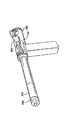
図7A〜図7Dは、様々な状態位置でのアプリケータを示す。図7Aは図6A〜図6Dに示したような位置Aに対応する。図7Bは図6A〜図6Dに示したような位置Bに対応する。図7Cは図6A〜図6Dに示したような位置Dに対応する。図7Dは図6A〜図6Dに示したような位置Fに対応する。 7A-7D show the applicator in various state positions. FIG. 7A corresponds to the position A as shown in FIGS. 6A to 6D. FIG. 7B corresponds to position B as shown in FIGS. 6A to 6D. FIG. 7C corresponds to the position D as shown in FIGS. 6A to 6D. FIG. 7D corresponds to the position F as shown in FIGS. 6A to 6D.
したがって、動作中に、シーケンス手段は、複数の異なる状態を仮定するために複数の部分をもたらす。初期設定後、各部分は位置Aにあって拡張部が圧縮している状態で開創器部が完全に伸びた位置にある(図7A参照)。この初期位置において、開創器部の套管針(トロカール:trocar)がすでに切断すべき臓器壁に通されて、圧縮された拡張部が臓器内に配置されている。 Thus, during operation, the sequencing means provides multiple parts to assume multiple different states. After initial setting, each part is in position A and the retractor part is in a fully extended position with the expansion part compressed (see FIG. 7A). In this initial position, the retractor trocar is already passed through the organ wall to be cut and the compressed expansion is placed in the organ.
外科医はシーケンス手順を開始する準備をする時、シーケンス・ボルト650を位置A(図7A)から位置B(図7B)に移動させる。この移動により、(シーケンス・ボルト650の)プランジャカム従動子750は、シリンダカムスロットと、押圧カムスロットと、安全ラッチカムスロット内それぞれの第1の位置(A)から第2の位置(B)に移動される。この移動により、開創器部が穴形成部に対して完全拡張状態に保持している間、拡張部は完全拡張状態に拡張される。したがって、この時に、拡張部が臓器内で完全拡張状態になる(図7B参照)。
When the surgeon prepares to begin the sequence procedure, he moves the
そこで、シーケンス・ボルト650はシリンダカムスロットと、押圧カムスロットと、安全ラッチカムスロット内で位置Bから位置Cに回転されることにより、拡張部を完全に拡張した状態で開創器部を完全伸張状態に保持させる。これは、安全ラッチカム従動子770を押圧ラッチカムスロット741内の位置Cに保持させる間、開創器カム従動子760を開創器カムスロット730内の位置Cに配置する回転ステップである。
The
シーケンス・ボルト650は位置Cに達すると、圧縮スプリング540は開創器センブリと拡張部530を位置Dの方向に付勢する。この移動は、いくつかの構成要素に影響を与える。例えば、シーケンス・ボルト650が位置Cから位置Dに移動する際に、拡張部530を切断部210に向かって付勢されることにより、切断部210が臓器壁に接触するようになる。そこで、外科医は、臓器壁を貫通して切断するために切断部210を押したり、回転することにより組織プラグが作成される。シーケンス・ボルト650が位置Dに達すると、切断部210が完全拡張した拡張部530に接触することにより、臓器壁の切断工程が完了する。また、シーケンス・ボルト650は位置Cから位置Dに移動する際に、開創器カム従動子760を開創器カムスロット730内で位置CからDに移動させ、安全ラッチカム従動子770を開創器ラッチスロット742内で位置Dに保持させる。したがって、位置Cから位置Dに移動させることの正味の影響は、開創器部を穴形成部に向かって移動させることにより、切断部210を用いて穴を形成し、この工程を通して拡張部を完全拡張状態に保持させる。図7Cは、シーケンス・ボルト650が位置Dにある時のアプリケータの状態を示す。
When
第4の状態は、シーケンス・ボルト650が位置Dに固定されている状態である。この状態は本発明に係る安全ラッチを用いることにより可能である。図7Cに示すように、シーケンス・ボルト650は、位置Dで安全ラッチカムスロット740の傾けられた部分に配置され、安全ラッチカムスロット740の一面に軸方向に隣接することによって、安全ラッチに対してシーケンス・ボルト650のさらに軸方向の移動を防止する。したがって、この位置で拡張部を完全拡張状態に保持させる。また、位置Dにおいて、拡張部530は切断部210の切断端部に接触する。位置Dにおいて、拡張部530は十分な堅さを有し、切断部210の切断端部が、心臓の場合、心室である臓器内壁に切断部210の切断端部が接触することを防止するため、切断部210より十分大きい直径を有する。コネクタ導管を用いれば、切断面から臓器内壁を保護し、外科医がコネクタ導管を最終位置に配置するために回したり押したりすることを可能にする。
The fourth state is a state in which the
使用者が臓器からアプリケータを抜き出す準備をする時(例えば、コネクタ導管が使用して最終位置に配置されている場合)、シーケンス・ボルト650に対して安全ラッチ部を意図的に回すためにレバー781または溝付き面782を用いてもよい。この動作により、シーケンス・ボルト650は安全ラッチカムスロット740内で位置Dから位置Eに再配置される。この再配置中に、シーケンス・ボルト650の位置は、押圧カムスロット720又はシリンダカムスロット710に対して変化しない。
A lever to intentionally turn the safety latch relative to the
安全ラッチ部がシーケンス・ボルト650に対して回転されるとすぐに、シーケンス・ボルト650は安全ラッチカムスロット740内の位置Eに再配置され、シーケンス・ボルト650が安全ラッチカムスロット740の一面に軸方向に隣接し、拡張部530の圧縮からの圧力はシーケンス・ボルト650を位置Fに向けて軸方向に付勢する。シーケンス・ボルト650が位置Fに達すると、拡張部530は完全拡張状態から部分拡張状態に押し縮められる。図7Dに示すように、シーケンス・ボルト650が位置Fに達すると、部分拡張した拡張部530が、再度、切断部210に押し付けられることは、コネクタ導管を用いれば、アプリケータを臓器から抜き取るために理想的である。
As soon as the safety latch is rotated relative to the
安全ラッチのデザインは、シーケンス・ボルト650が回転前に位置Dにあるときだけ、拡張部530の部分拡張になる結果として押圧部300に対してラッチシリンダ780の回転を保証する。このデザインは、シーケンス・ボルト650が位置Dにある前に、外科医が意図的又は不注意に解除できない安全ラッチを提供する。
The safety latch design ensures rotation of the
したがって、安全ラッチ部を用いることによって、拡張部を位置Dで完全拡張状態にとどまらせ、外科医が意図的に選択するまで、拡張部が完全拡張状態から部分拡張状態に変化することが防止される。拡張部を完全拡張状態に保持することにより、安全ラッチは穴形成部の切断部が完全拡張された拡張部により完全に被覆されることを可能にすることにより、穴形成部の切断部に対する臓器の内面の露出を防止し、臓器の内面に損傷が発生する可能性を防止する。 Thus, by using the safety latch, the extension remains in the fully expanded state at position D and prevents the extension from changing from the fully expanded state to the partially expanded state until the surgeon intentionally selects it. . By holding the extension in the fully expanded state, the safety latch allows the cut in the hole forming part to be completely covered by the fully expanded extension, thereby providing an organ for the cut in the hole forming part. To prevent the exposure of the inner surface of the organ and the possibility of damage to the inner surface of the organ.
さらに、状況によって、外科医は穴にコネクタ導管を同時に挿入せずに、心臓のような管腔臓器壁に穴を開けたい場合がある。したがって、本発明はコネクタ導管または他の機器を同時に挿入する必要がなく、心臓の壁に穴を開けるためだけに用いてもよい。別のステップとしてコネクタ導管を穴に移植するようにしてもよい。 Further, in some situations, the surgeon may wish to make a hole in a luminal organ wall such as the heart without simultaneously inserting a connector conduit into the hole. Thus, the present invention does not require the simultaneous insertion of a connector conduit or other instrument and may be used only to puncture the heart wall. As another step, the connector conduit may be implanted in the hole.
さらに、本発明によって、遠心端に切断部を有する穴形成部で臓器壁に穴を形成し、前記穴形成部に組み合わされ、開創器部と動作的に組み合わされる配置手段で前記穴形成部を配置し、前記穴形成部に関連する前記開創器部の相対動作を前記シーケンス手段で連続した方法で調整することにより、前記管腔臓器壁に穴を形成する手順を実施ことを特徴とする管腔臓器に穴を形成する方法が提供される。 Further, according to the present invention, a hole is formed in an organ wall by a hole forming part having a cutting part at a distal end, and the hole forming part is combined with the hole forming part and operatively combined with a retractor part. Placing and adjusting the relative movement of the retractor part relative to the hole forming part in a sequential manner by the sequence means to implement a procedure for forming a hole in the luminal organ wall A method of forming a hole in a hollow organ is provided.
前記開創器は、前記穴形成部内に移動可能に配置される開創器本体と、前記開創器本体の遠心端に配置される拡張可能な拡張部と、を具備してもよい。 The retractor may comprise a retractor body movably disposed within the hole forming portion and an expandable extension disposed at a distal end of the retractor body.
前記拡張部は非拡張状態から完全拡張状態と部分拡張状態に拡張可能であることを具備してもよい。 The expansion unit may be expandable from a non-expanded state to a fully expanded state and a partially expanded state.
前記シーケンス手段は前記拡張部の拡張を前記非拡張状態から前記完全拡張状態と前記部分拡張状態に連続した方法で制御することを具備してもよい。 The sequence means may comprise controlling the expansion of the expansion unit in a continuous manner from the non-expanded state to the fully expanded state and the partially expanded state.
前記シーケンス手段は前記開創器と前記穴形成部と動作的に組み合わせられる安全ラッチ部をさらに具備してもよい。 The sequencing means may further comprise a safety latch part operatively associated with the retractor and the hole forming part.
前記シーケンス手段は、前記開創器内に形成されたシリンダカムスロットを通して伸ばされるシーケンス・ボルトと、押圧部内に形成された押圧カムスロットと、前記安全ラッチ部内に形成された安全カムスロットと、を具備してもよい。 The sequence means includes a sequence bolt extended through a cylinder cam slot formed in the retractor, a press cam slot formed in a press portion, and a safety cam slot formed in the safety latch portion. May be.
前記シーケンス手段は、順次に以下の状態を仮定する要素を引き起こすための手段を備え、 Said sequence means comprises means for inducing elements which in turn assume the following conditions:
(a)前記シーケンス・ボルトが前記シリンダカムスロットと前記押圧カムスロットと前記安全ラッチカムスロットの各々を第1の位置から第2の位置に移動させることにより、前記穴形成部に対して完全伸張位置に前記開創器部を保持しながら前記拡張部を前記完全拡張状態に拡張する第1の状態と、(A) The sequence bolt fully extends with respect to the hole forming portion by moving each of the cylinder cam slot, the pressing cam slot, and the safety latch cam slot from the first position to the second position. A first state of expanding the expansion portion to the fully expanded state while holding the retractor portion in position;
(b)前記シーケンス・ボルトが前記シリンダカムスロットと前記押圧カムスロットと前記安全カラッチムスロットの各々を前記第2の位置から第3の位置に移動させることにより、前記完全拡張状態で前記拡張部を保持し、前記完全伸張位置に前記開創器を保持する第2の状態と、(B) The sequence bolt moves each of the cylinder cam slot, the pressing cam slot, and the safety caratomic slot from the second position to the third position, so that the expansion portion is in the fully expanded state. A second state of holding the retractor in the fully extended position;
(c)前記シーケンス・ボルトが前記シリンダカムスロットと前記押圧カムスロットと前記安全ラッチカムスロットの各々を前記第3の位置から第4の位置に移動させることにより、前記完全拡張状態に前記拡張部を保持しながら前記開創器が前記穴形成部に向かって移動することを許可する第3の状態と、(C) The sequence bolt moves each of the cylinder cam slot, the pressing cam slot, and the safety latch cam slot from the third position to the fourth position, thereby bringing the expansion portion into the fully expanded state. A third state allowing the retractor to move toward the hole forming part while holding
(d)前記シーケンス・ボルトが前記安全ラッチカムスロットと前記シリンダカムスロットと前記押圧カムスロットの各々を前記第4の位置に固定させることにより、前記完全拡張状態に前記拡張部を保持する第4の状態と、(D) The sequence bolt holds the expansion portion in the fully expanded state by fixing each of the safety latch cam slot, the cylinder cam slot, and the pressing cam slot to the fourth position. The state of
(e)前記安全ラッチ部が前記シリンダカムスロットと前記押圧カムスロットの各々を前記第4の位置に保持しながら、前記シーケンス・ボルトが前記安全ラッチカムスロットを前記第4の位置から第5の位置に再配置させるように前記開創器部に対して前記安全ラッチ部を移動させることにより、前記拡張部を前記完全拡張状態から解除する第5の状態と、(E) While the safety latch portion holds each of the cylinder cam slot and the pressing cam slot in the fourth position, the sequence bolt moves the safety latch cam slot from the fourth position to the fifth position. A fifth state in which the extension portion is released from the fully extended state by moving the safety latch portion relative to the retractor portion to be repositioned in position;
(f)前記シーケンス・ボルトが前記安全ラッチカムスロットを前記第5の位置から第6の位置に移動させると同時に、前記シリンダカムスロットと前記押圧カムスロットの各々を前記第4の位置から前記第5の位置に移動させて、前記拡張部が前記部分拡張状態になることを許可する第6の状態と、を具備してもよい。(F) The sequence bolt moves the safety latch cam slot from the fifth position to the sixth position, and simultaneously moves each of the cylinder cam slot and the pressing cam slot from the fourth position to the second position. And a sixth state in which the extended portion is allowed to enter the partially expanded state.
前記臓器は心臓であってもよい。 The organ may be a heart.
コネクタ導管が前記穴形成部に組み合わせられてもよい。 A connector conduit may be combined with the hole forming portion.
前記拡張部はバルーンであってもよい。 The extension may be a balloon.
前記拡張部は拡張可能なスポンジであってもよい。 The extension may be an expandable sponge.
前記拡張部は傘状の機構であってもよい。 The extension part may be an umbrella-like mechanism.
前記シーケンス手段はカム機構を具備してもよい。 The sequence means may comprise a cam mechanism.
前記シーケンス手段はギア機構を具備してもよい。 The sequence means may comprise a gear mechanism.
前記シーケンス手段は、前記配置手段と動作的に組み合わせられる少なくとも一つのサーボ機構と、前記少なくとも一つのサーボ機構と動作的に組み合わせられるコントローラと、を具備してもよい。 The sequence means may comprise at least one servo mechanism operatively combined with the arrangement means and a controller operably combined with the at least one servo mechanism.
前記シーケンス手段と動作的に組み合わされるボタンを更に具備し、前記ボタンの押し下げにより前記シーケンス手段を始動させることにより、前記臓器壁内に前記コネクタ導管を移植するための手順のステップを達成してもよい。 The method further comprises a button operatively associated with the sequencing means, and activating the sequencing means by depressing the button to achieve a procedural step for implanting the connector conduit within the organ wall Good.
210 切断部
300 押圧部
500 開創器
530 拡張部
650 シーケンス・ボルト
720 押圧カムスロット
740 安全ラッチカムスロット
741 押圧ラッチカムスロット
750 プランジャカム従動子
770 安全ラッチカム従動子
780 ラッチシリンダ
781 レバー
210 cutting
Claims (11)
前記穴形成部内で回転及び軸方向へ移動可能に配置されるとともに、シリンダカムスロットが貫通形成されたシリンダー部をその基端側に、前記穴形成部の内径よりも小径な先端部をその先端側に夫々有する開創器本体と、
前記開創器本体のシリンダー部に挿入されるピストン及び前記シリンダカムスロット及び前記押圧カムスロットを貫通したカムフォロワを有するシーケンスボルトと、
前記開創器本体の前記先端部の先端近傍に配置され、前記シーケンスボルトの前記開創器本体に対する位置に応じて、前記穴形成部の内径よりも小径な非拡張状態,前記穴形成部の内径と同径である部分拡張状態及び前記穴形成部よりも大径である完全拡張状態まで拡縮可能な拡張部と、
前記穴形成部に対して回転のみ可能に嵌められているとともに前記カムフォロワが係合する安全ラッチカムスロットが形成された環状部材からなるラッチリングと、
前記カムフォロワ,前記押圧カムスロット,前記シリンダカムスロット,前記ラッチカムスロット及び前記カムフォロワを構成要素とし、前記開創器本体が前記穴形成部に対して前記拡張部が前記切断部の先端から離れた突出位置にあり且つ前記シーケンスボルトが前記開創器本体に対して前記ピストンを最も押し込んだ完全拡張位置にある状態から、前記シーケンスボルトと前記開創器本体との相対位置を維持したまま前記開創器本体のみ前記穴形成部に対して前記完全拡張状態にある前記拡張部が前記切断部の先端を覆う中間位置まで移動することを許容し、次に、前記ラッチリングが前記穴形成部に対して回転されることにより、前記シーケンスボルトのみ前記開創器本体に対して前記拡張部が前記部分拡張状態となる部分拡張位置まで移動することを許容し、次に、前記シーケンスボルトと前記開創器本体との相対位置を維持したまま前記開創器本体のみ前記穴形成部に対して前記部分拡張状態にある前記拡張部が前記穴形成部内に収容される収容位置まで移動することを許容することにより、前期管腔臓器壁に前記穴を形成するための手続を実施するシーケンス手段と
を具備することを特徴とする管腔臓器壁に穴を形成するアプリケータ。 It has an annular cutting part at the tip and a cylindrical pressing member through which a pressing cam slot is formed, and when the cutting part is pressed against the luminal organ wall, a hole is formed in the luminal organ wall A hole forming part to be
The cylinder portion in which the cylinder cam slot is formed penetratingly formed is arranged at the base end side, and the tip portion smaller than the inner diameter of the hole forming portion is arranged at the tip end. A retractor body on each side,
A sequence bolt having a piston inserted into a cylinder portion of the retractor body and a cam follower penetrating the cylinder cam slot and the pressing cam slot;
An unexpanded state that is disposed near the tip of the tip of the retractor body, and is smaller in diameter than the inner diameter of the hole forming portion, depending on the position of the sequence bolt with respect to the retractor body, and the inner diameter of the hole forming portion An expanded portion that can be expanded and contracted to a partially expanded state that is the same diameter and a fully expanded state that is larger than the hole forming portion;
A latch ring formed of an annular member that is fitted to the hole forming portion so as to be rotatable only and is formed with a safety latch cam slot that engages with the cam follower;
The cam follower, the pressing cam slot, the cylinder cam slot, the latch cam slot, and the cam follower are constituent elements, and the retractor body protrudes away from the tip of the cutting portion with respect to the hole forming portion. from a state with the piston in the position and the sequence bolt relative to the retractor body most pushed it fully extended position, only the retractor body while maintaining the relative position of the sequence bolt and the retractor body The extension portion in the fully expanded state with respect to the hole forming portion is allowed to move to an intermediate position covering the tip of the cutting portion, and then the latch ring is rotated with respect to the hole forming portion. the Rukoto, partially expanded position or the extension portion relative to the retractor body only the sequence bolt is the partial expanded state Was allowed to move, then the extension portion in the partial expanded state relative to the retractor body only the hole forming element while maintaining the relative position of the sequence bolt and the retractor body said hole A luminal organ wall comprising sequence means for performing a procedure for forming the hole in the pre-luminal organ wall by allowing movement to an accommodating position accommodated in the forming portion Applicator to form a hole in the.
(a)前記シーケンス・ボルトが前記カムフォロワを前記シリンダカムスロットと前記押圧カムスロットと前記安全ラッチカムスロットの各々における第1の位置から第2の位置に移動させることにより、前記穴形成部に対して完全伸張位置に前記開創器本体を保持しながら前記拡張部を前記完全拡張状態に拡張する第1の状態と、
(b)前記シーケンス・ボルトが前記カムフォロワを前記シリンダカムスロットと前記押圧カムスロットと前記安全ラッチカムスロットの各々における前記第2の位置から第3の位置に移動させることにより、前記拡張部を前記完全拡張状態に維持し、前記突出位置に前記開創器本体を保持する第2の状態と、
(c)前記シーケンス・ボルトが前記カムフォロワを前記シリンダカムスロットと前記押圧カムスロットと前記安全ラッチカムスロットの各々における前記第3の位置から第4の位置に移動させることにより、前記拡張部を前記完全拡張状態に維持しながら前記開創器本体が前記穴形成部に対して移動することを許可する第3の状態と、
(d)前記シーケンス・ボルトが前記カムフォロワを前記安全ラッチカムスロットと前記シリンダカムスロットと前記押圧カムスロットの各々における前記第4の位置に固定させることにより、前記拡張部を前記完全拡張状態に維持する第4の状態と、
(e)前記安全ラッチ部が前記シリンダカムスロットと前記押圧カムスロットの各々を前記第4の位置に保持しながら、前記シーケンス・ボルトの前記カムフォロワを前記安全ラッチカムスロットの前記第4の位置から第5の位置に再配置させるように前記開創器本体に対して前記安全ラッチ部を移動させることにより、前記拡張部を前記完全拡張状態から解除可能とする第5の状態と、
(f)前記シーケンス・ボルトが前記カムフォロワを前記安全ラッチカムスロットを前記第5の位置から第6の位置に移動させると同時に、前記シリンダカムスロットと前記押圧カムスロットの各々における前記第4の位置から前記第5の位置に移動させて、前記拡張部が前記部分拡張状態になることを許可する第6の状態と、
を具備することを特徴とする請求項1記載のアプリケータ。 Said sequence means comprises means for inducing elements which in turn assume the following conditions:
(A) The sequence bolt moves the cam follower from a first position to a second position in each of the cylinder cam slot, the pressing cam slot, and the safety latch cam slot, thereby preventing the hole forming portion from moving. A first state of expanding the extension portion to the fully expanded state while holding the retractor body in a fully extended position;
(B) The sequence bolt moves the cam follower from the second position to the third position in each of the cylinder cam slot, the pressing cam slot, and the safety latch cam slot, thereby moving the extension portion to the third position. Maintaining the fully expanded state and holding the retractor body in the protruding position;
(C) The sequence bolt moves the cam follower from the third position to the fourth position in each of the cylinder cam slot, the pressing cam slot, and the safety latch cam slot, thereby moving the extension portion to the fourth position. A third state allowing the retractor body to move relative to the hole forming portion while maintaining a fully expanded state;
(D) The sequence bolt maintains the expansion portion in the fully expanded state by fixing the cam follower in the fourth position in each of the safety latch cam slot, the cylinder cam slot, and the pressing cam slot. A fourth state to
(E) The safety latch portion holds the cylinder cam slot and the pressing cam slot in the fourth position, while the cam follower of the sequence bolt is moved from the fourth position of the safety latch cam slot. A fifth state in which the extension portion can be released from the fully expanded state by moving the safety latch portion relative to the retractor body so as to be rearranged in a fifth position;
(F) the sequence bolt moves the cam follower from the fifth position to the sixth position at the same time as the fourth position in each of the cylinder cam slot and the pressing cam slot. To the fifth position to allow the expansion portion to enter the partially expanded state; and
The applicator according to claim 1, further comprising:
ことを特徴とする請求項1記載のアプリケータ。 The applicator according to claim 1, wherein the organ is a heart.
ことを特徴とする請求項1記載のアプリケータ。 The applicator of claim 1, wherein a connector conduit is associated with the hole forming portion.
ことを特徴とする請求項1記載のアプリケータ。 The applicator according to claim 1, wherein the expansion portion is a balloon.
ことを特徴とする請求項1記載のアプリケータ。 The applicator according to claim 1, wherein the extension portion is an expandable sponge.
ことを特徴とする請求項1記載のアプリケータ。 The applicator according to claim 1, wherein the extension portion is an umbrella-like mechanism.
ことを特徴とする請求項1記載のアプリケータ。 The applicator according to claim 1, wherein the sequence means comprises a cam mechanism.
ことを特徴とする請求項1記載のアプリケータ。 The applicator according to claim 1, wherein the sequence means comprises a gear mechanism.
前記配置手段と動作的に組み合わされた少なくとも一つのサーボ機構と、
前記少なくとも一つのサーボ機構と動作的に組み合わされたコントローラと、を具備する
ことを特徴とする請求項1記載のアプリケータ。 The sequence means includes
At least one servo mechanism operatively associated with the positioning means;
The applicator of claim 1, further comprising a controller operatively associated with the at least one servomechanism.
前記ボタンの押し下げにより前記シーケンス手段を始動させることにより、前記臓器壁内に前記コネクタ導管を移植するための手順のステップを達成する
ことを特徴とする請求項10記載のアプリケータ。 Further comprising a button operatively associated with the sequencing means;
11. An applicator according to claim 10 , wherein the procedural step for implanting the connector conduit in the organ wall is accomplished by activating the sequencing means by depressing the button.
Applications Claiming Priority (3)
| Application Number | Priority Date | Filing Date | Title |
|---|---|---|---|
| US72622205P | 2005-10-14 | 2005-10-14 | |
| US60/726,222 | 2005-10-14 | ||
| PCT/US2006/040230 WO2007081418A1 (en) | 2005-10-14 | 2006-10-16 | Apparatus and method for forming a hole in a hollow organ |
Publications (3)
| Publication Number | Publication Date |
|---|---|
| JP2009523034A JP2009523034A (en) | 2009-06-18 |
| JP2009523034A5 JP2009523034A5 (en) | 2009-12-03 |
| JP5225850B2 true JP5225850B2 (en) | 2013-07-03 |
Family
ID=37776871
Family Applications (1)
| Application Number | Title | Priority Date | Filing Date |
|---|---|---|---|
| JP2008535748A Expired - Fee Related JP5225850B2 (en) | 2005-10-14 | 2006-10-16 | Apparatus and method for forming a hole in a luminal organ |
Country Status (13)
| Country | Link |
|---|---|
| EP (1) | EP1945111B1 (en) |
| JP (1) | JP5225850B2 (en) |
| CN (1) | CN101365389B (en) |
| AT (1) | ATE459294T1 (en) |
| AU (1) | AU2006335227B2 (en) |
| BR (1) | BRPI0618392A2 (en) |
| CA (1) | CA2626015C (en) |
| DE (1) | DE602006012720D1 (en) |
| IL (1) | IL190784A (en) |
| MX (1) | MX2008004898A (en) |
| NZ (1) | NZ568139A (en) |
| WO (1) | WO2007081418A1 (en) |
| ZA (1) | ZA200803810B (en) |
Families Citing this family (17)
| Publication number | Priority date | Publication date | Assignee | Title |
|---|---|---|---|---|
| ATE513516T1 (en) | 2005-01-21 | 2011-07-15 | Mayo Foundation | THORASCOPIC HEART VALVE REPAIR DEVICE |
| US8414603B2 (en) | 2007-09-25 | 2013-04-09 | Correx, Inc. | Applicator, assembly, and method for connecting an inlet conduit to a hollow organ |
| JP5357167B2 (en) | 2007-10-18 | 2013-12-04 | ネオコード インコーポレイテッド | Instrument for repairing pulsating leaflets in the heart with minimal invasiveness |
| JP5797115B2 (en) | 2008-12-19 | 2015-10-21 | ケイエル メディカル エルエルシー | Devices and systems for endoscopic access to the heart |
| US9044221B2 (en) | 2010-12-29 | 2015-06-02 | Neochord, Inc. | Exchangeable system for minimally invasive beating heart repair of heart valve leaflets |
| US20130035757A1 (en) | 2011-06-01 | 2013-02-07 | John Zentgraf | Minimally invasive repair of heart valve leaflets |
| CN104337553A (en) * | 2013-08-05 | 2015-02-11 | 北京精密机电控制设备研究所 | Heart hole opener |
| WO2017059406A1 (en) | 2015-10-01 | 2017-04-06 | Neochord, Inc. | Ringless web for repair of heart valves |
| US10213306B2 (en) | 2017-03-31 | 2019-02-26 | Neochord, Inc. | Minimally invasive heart valve repair in a beating heart |
| WO2019183626A1 (en) | 2018-03-23 | 2019-09-26 | Neochord, Inc. | Device for suture attachment for minimally invasive heart valve repair |
| CN108478258B (en) * | 2018-04-28 | 2019-11-12 | 魏翔 | Chambers of the heart myocardium cutter |
| US11253360B2 (en) | 2018-05-09 | 2022-02-22 | Neochord, Inc. | Low profile tissue anchor for minimally invasive heart valve repair |
| US11173030B2 (en) | 2018-05-09 | 2021-11-16 | Neochord, Inc. | Suture length adjustment for minimally invasive heart valve repair |
| CA3112020C (en) | 2018-09-07 | 2023-10-03 | Neochord, Inc. | Device for suture attachment for minimally invasive heart valve repair |
| US11207102B2 (en) | 2018-09-12 | 2021-12-28 | Lsi Solutions, Inc. | Minimally invasive specimen retrieval system and methods thereof |
| WO2020214818A1 (en) | 2019-04-16 | 2020-10-22 | Neochord, Inc. | Transverse helical cardiac anchor for minimally invasive heart valve repair |
| US11452544B1 (en) | 2021-04-29 | 2022-09-27 | Xiang Wei | Intra-cardiac myocardial resection device |
Family Cites Families (6)
| Publication number | Priority date | Publication date | Assignee | Title |
|---|---|---|---|---|
| CN1028601C (en) * | 1990-05-18 | 1995-05-31 | 中国人民解放军沈阳军区总医院 | Heart catheter knife |
| US5192290A (en) * | 1990-08-29 | 1993-03-09 | Applied Medical Resources, Inc. | Embolectomy catheter |
| CN2388920Y (en) * | 1999-03-22 | 2000-07-26 | 郑国强 | Multi-function apparatus for cardiac valve replacement operation |
| US6652542B2 (en) * | 1999-04-16 | 2003-11-25 | Integrated Vascular Interventional Technologies, L.C. (Ivit, Lc) | External anastomosis operators and related systems for anastomosis |
| US6699256B1 (en) * | 1999-06-04 | 2004-03-02 | St. Jude Medical Atg, Inc. | Medical grafting apparatus and methods |
| EP1761202A4 (en) * | 2004-03-23 | 2012-06-13 | Correx Inc | Apparatus and method for connecting a conduit to a hollow organ |
-
2006
- 2006-10-16 MX MX2008004898A patent/MX2008004898A/en active IP Right Grant
- 2006-10-16 AU AU2006335227A patent/AU2006335227B2/en not_active Ceased
- 2006-10-16 CA CA2626015A patent/CA2626015C/en not_active Expired - Fee Related
- 2006-10-16 JP JP2008535748A patent/JP5225850B2/en not_active Expired - Fee Related
- 2006-10-16 AT AT06816933T patent/ATE459294T1/en not_active IP Right Cessation
- 2006-10-16 ZA ZA200803810A patent/ZA200803810B/en unknown
- 2006-10-16 NZ NZ568139A patent/NZ568139A/en not_active IP Right Cessation
- 2006-10-16 CN CN2006800449226A patent/CN101365389B/en not_active Expired - Fee Related
- 2006-10-16 EP EP06816933A patent/EP1945111B1/en not_active Not-in-force
- 2006-10-16 WO PCT/US2006/040230 patent/WO2007081418A1/en active Application Filing
- 2006-10-16 BR BRPI0618392-1A patent/BRPI0618392A2/en not_active IP Right Cessation
- 2006-10-16 DE DE602006012720T patent/DE602006012720D1/en active Active
-
2008
- 2008-04-10 IL IL190784A patent/IL190784A/en not_active IP Right Cessation
Also Published As
| Publication number | Publication date |
|---|---|
| NZ568139A (en) | 2010-10-29 |
| CN101365389B (en) | 2011-07-06 |
| IL190784A (en) | 2014-04-30 |
| BRPI0618392A2 (en) | 2012-09-25 |
| CA2626015C (en) | 2015-03-17 |
| JP2009523034A (en) | 2009-06-18 |
| ATE459294T1 (en) | 2010-03-15 |
| ZA200803810B (en) | 2009-08-26 |
| IL190784A0 (en) | 2008-11-03 |
| CA2626015A1 (en) | 2007-07-19 |
| EP1945111A1 (en) | 2008-07-23 |
| CN101365389A (en) | 2009-02-11 |
| WO2007081418A1 (en) | 2007-07-19 |
| MX2008004898A (en) | 2008-11-19 |
| EP1945111B1 (en) | 2010-03-03 |
| AU2006335227B2 (en) | 2013-06-13 |
| AU2006335227A1 (en) | 2007-07-19 |
| DE602006012720D1 (en) | 2010-04-15 |
Similar Documents
| Publication | Publication Date | Title |
|---|---|---|
| JP5225850B2 (en) | Apparatus and method for forming a hole in a luminal organ | |
| US8679138B2 (en) | Apparatus and method for forming a hole in a hollow organ | |
| JP2009523034A5 (en) | ||
| US11129640B2 (en) | Surgical punch | |
| US7510561B2 (en) | Apparatus and method for connecting a conduit to a hollow organ | |
| US20200101210A1 (en) | Devices, systems, and methods for implanting and using a connector in a tissue wall | |
| US10499949B2 (en) | Systems for implanting and using a conduit within a tissue wall | |
| WO2012158968A2 (en) | Needle guard, assembly and method of implanting a heart assist system |
Legal Events
| Date | Code | Title | Description |
|---|---|---|---|
| A521 | Request for written amendment filed |
Free format text: JAPANESE INTERMEDIATE CODE: A523 Effective date: 20091015 |
|
| A621 | Written request for application examination |
Free format text: JAPANESE INTERMEDIATE CODE: A621 Effective date: 20091015 |
|
| A977 | Report on retrieval |
Free format text: JAPANESE INTERMEDIATE CODE: A971007 Effective date: 20111222 |
|
| A131 | Notification of reasons for refusal |
Free format text: JAPANESE INTERMEDIATE CODE: A131 Effective date: 20120110 |
|
| A601 | Written request for extension of time |
Free format text: JAPANESE INTERMEDIATE CODE: A601 Effective date: 20120409 |
|
| A602 | Written permission of extension of time |
Free format text: JAPANESE INTERMEDIATE CODE: A602 Effective date: 20120416 |
|
| A601 | Written request for extension of time |
Free format text: JAPANESE INTERMEDIATE CODE: A601 Effective date: 20120508 |
|
| A602 | Written permission of extension of time |
Free format text: JAPANESE INTERMEDIATE CODE: A602 Effective date: 20120515 |
|
| A601 | Written request for extension of time |
Free format text: JAPANESE INTERMEDIATE CODE: A601 Effective date: 20120608 |
|
| A602 | Written permission of extension of time |
Free format text: JAPANESE INTERMEDIATE CODE: A602 Effective date: 20120615 |
|
| A521 | Request for written amendment filed |
Free format text: JAPANESE INTERMEDIATE CODE: A523 Effective date: 20120710 |
|
| A131 | Notification of reasons for refusal |
Free format text: JAPANESE INTERMEDIATE CODE: A131 Effective date: 20121016 |
|
| A521 | Request for written amendment filed |
Free format text: JAPANESE INTERMEDIATE CODE: A523 Effective date: 20130115 |
|
| TRDD | Decision of grant or rejection written | ||
| A01 | Written decision to grant a patent or to grant a registration (utility model) |
Free format text: JAPANESE INTERMEDIATE CODE: A01 Effective date: 20130212 |
|
| A61 | First payment of annual fees (during grant procedure) |
Free format text: JAPANESE INTERMEDIATE CODE: A61 Effective date: 20130313 |
|
| R150 | Certificate of patent or registration of utility model |
Free format text: JAPANESE INTERMEDIATE CODE: R150 |
|
| FPAY | Renewal fee payment (event date is renewal date of database) |
Free format text: PAYMENT UNTIL: 20160322 Year of fee payment: 3 |
|
| R250 | Receipt of annual fees |
Free format text: JAPANESE INTERMEDIATE CODE: R250 |
|
| LAPS | Cancellation because of no payment of annual fees |