JP5224912B2 - Vibration monitoring apparatus and monitoring method - Google Patents
Vibration monitoring apparatus and monitoring method Download PDFInfo
- Publication number
- JP5224912B2 JP5224912B2 JP2008143083A JP2008143083A JP5224912B2 JP 5224912 B2 JP5224912 B2 JP 5224912B2 JP 2008143083 A JP2008143083 A JP 2008143083A JP 2008143083 A JP2008143083 A JP 2008143083A JP 5224912 B2 JP5224912 B2 JP 5224912B2
- Authority
- JP
- Japan
- Prior art keywords
- vibration
- measurement object
- ultrasonic
- frequency
- reception
- Prior art date
- Legal status (The legal status is an assumption and is not a legal conclusion. Google has not performed a legal analysis and makes no representation as to the accuracy of the status listed.)
- Active
Links
Images


Landscapes
- Measurement Of Mechanical Vibrations Or Ultrasonic Waves (AREA)
Description
本件発明は、構造物の振動監視装置及び監視方法に関し、特に、構造物の内部にある測定対象物の振動を構造物の外部から超音波送受信装置により測定する振動監視装置及び監視方法に関する。 The present invention relates to a vibration monitoring apparatus and a monitoring method for a structure, and more particularly, to a vibration monitoring apparatus and a monitoring method for measuring vibration of a measurement object inside a structure from the outside of the structure by an ultrasonic transmission / reception apparatus.
従来の非破壊検査装置において、容器内部や容器内を流れる流路の内側にある検査対象物の振動を非破壊で監視する方法として、測定対象物に加速度計を設け直接振動を監視する方法、外部に設けた超音波送受信装置により測定対象物の振動を監視する方法が用いられている。 In a conventional non-destructive inspection apparatus, as a method for non-destructively monitoring the vibration of the inspection object inside the container or inside the flow path flowing through the container, a method of directly monitoring the vibration by providing an accelerometer on the measurement object, A method of monitoring the vibration of an object to be measured by an ultrasonic transmission / reception device provided outside is used.
超音波を用いた振動監視方法は、容器の外部に設置した超音波送受信装置から検査対象物に向けて超音波を発信し、容器の壁と容器内の媒質を伝わって検査対象物に入射した超音波は検査対象物から反射され、その超音波を受信してその伝播時間を計測するとともに、超音波の媒質中での伝播速度を考慮して距離に換算する。このプロセスを高速に繰り返すことで、測定対象物の振動変位量を計測し、測定対象物の構造物の異常を検出するものである。 In the vibration monitoring method using ultrasonic waves, ultrasonic waves are transmitted from the ultrasonic transmission / reception device installed outside the container toward the inspection object, and are transmitted to the inspection object through the container wall and the medium in the container. The ultrasonic wave is reflected from the object to be inspected, and the ultrasonic wave is received to measure the propagation time, and converted into a distance in consideration of the propagation speed of the ultrasonic wave in the medium. By repeating this process at high speed, the vibration displacement amount of the measurement object is measured, and an abnormality of the structure of the measurement object is detected.
このような超音波を用いた振動監視装置として、特許文献1には、原子炉圧力容器内の炉内構造物を監視するために、圧力容器の外側に設置した超音波送受信装置から超音波を炉内構造物に向けて送受信し、信号処理により炉内構造物の振動に基づく超音波の伝搬時間の変化分を測定することにより、炉内構造物の振動を監視することが記載されている。
As a vibration monitoring apparatus using such ultrasonic waves,
また、特許文献2には、容器内に設置された電動ポンプの回転軸の振動を監視するために、容器外部に設置された超音波送受信装置から超音波を回転軸に向けて送受信し、反射波形を周波数解析等を用いて信号処理することにより、回転軸の変位を測定し、電動ポンプの振動を監視することが記載されている。
上述した加速度計を直接検査対象物に取り付ける従来の振動監視方法では、測定対象物が複数箇所に及ぶ場合、加速度計も多数設置する必要があるほか、測定対象物の動作に影響を及ぼしたり、複雑な配線が必要になったり、また、加速度計の劣化、脱落等、コスト上及び構造上、多くの問題があった。 In the conventional vibration monitoring method in which the above-mentioned accelerometer is directly attached to the inspection object, when the measurement object extends to a plurality of places, it is necessary to install a large number of accelerometers, and it affects the operation of the measurement object. There have been many problems in terms of cost and structure, such as the need for complicated wiring, and deterioration and dropout of the accelerometer.
また、上述した超音波を用いた振動監視装置では、容器や流路の外側から内部にある構造物の振動を監視することが可能であるが、容器や流路と振動を計測する対象物との間に、中間構造物が存在する場合、容器の外側から発信された超音波の大部分は中間構造物で反射されるため、測定対象物の振動を正確に計測できない問題があった。 Further, in the vibration monitoring apparatus using the ultrasonic wave described above, it is possible to monitor the vibration of the structure inside from the outside of the container and the flow path. When an intermediate structure is present between them, most of the ultrasonic waves transmitted from the outside of the container are reflected by the intermediate structure, which causes a problem that the vibration of the measurement object cannot be accurately measured.
このような場合、超音波の伝搬の妨害とならないように中間構造物に開口部を設けることにより、測定対象物の振動を計測することが可能ではあるが、開口を設けるために構造物の改造が必要となる問題があった。 In such a case, it is possible to measure the vibration of the measurement object by providing an opening in the intermediate structure so as not to interfere with the propagation of ultrasonic waves, but the structure is modified to provide an opening. There was a problem that required.
本発明は上記課題を解決するためになされたものであり、容器等の構造物と前記構造物内の測定対象物との間に中間構造物がある場合においても、超音波を効率よく伝播させ、測定対象物の振動を高精度で監視することができる振動監視装置および監視方法を提供することを目的とする。 The present invention has been made in order to solve the above-described problems, and allows ultrasonic waves to propagate efficiently even when there is an intermediate structure between a structure such as a container and a measurement object in the structure. An object of the present invention is to provide a vibration monitoring apparatus and a monitoring method capable of monitoring the vibration of a measurement object with high accuracy.
上記課題を解決するために、本発明に係る振動監視装置は、構造物と前記構造物内の測定対象物との間に中間構造物を有する構造物の振動監視装置において、前記構造物の外壁に設けられ測定対象物に超音波を発信し受信波を受信する超音波送受信装置と、受信波をデジタル値に変換するA/D変換装置と、前記デジタル値を演算処理し受信信号の時間波形形状の変化から測定対象物の振動変位を計測し、前記測定対象物の振動値と振動周波数を算出する信号処理装置と、前記振動値又は振動周波数の変化を監視することにより前記測定対象物の異常を判定する異常判定装置と、を備え、前記超音波送受信装置は、当該超音波送受信装置から発信される超音波の周波数を変化させて受信波のエコーレベルが最大となる周波数を決定することによって、前記測定対象物に発信する超音波の波長を、nを整数としたとき前記中間構造物の厚さの2/n倍に設定することを特徴とする。 In order to solve the above-described problems, a vibration monitoring apparatus according to the present invention is a vibration monitoring apparatus for a structure having an intermediate structure between a structure and a measurement object in the structure. An ultrasonic transmission / reception device that transmits ultrasonic waves to a measurement object and receives reception waves, an A / D conversion device that converts the reception waves into digital values, and a time waveform of a received signal by performing arithmetic processing on the digital values A signal processing device that measures a vibration displacement of the measurement object from a change in shape, calculates a vibration value and a vibration frequency of the measurement object, and monitors a change in the vibration value or vibration frequency of the measurement object. An abnormality determination device for determining an abnormality, wherein the ultrasonic transmission / reception device changes a frequency of an ultrasonic wave transmitted from the ultrasonic transmission / reception device to determine a frequency at which an echo level of the received wave is maximum. In I, an ultrasonic wave of sending to the measurement object, and sets the 2 / n times the thickness of the intermediate structure where n is an integer.
また、本発明に係る振動監視方法は、構造物と前記構造物内の測定対象物との間に中間構造物を有する構造物の振動監視方法において、前記構造物の外壁に設けられた超音波送受信装置から発信される超音波の周波数を変化させて受信波のエコーレベルが最大となる周波数を決定することによって、前記測定対象物に発信する超音波の波長を、nを整数としたとき前記中間構造物の厚さの2/n倍に設定するとともに、当該波長の超音波を前記測定対象物に発信し、受信波をデジタル値に変換し、前記デジタル値を演算処理し受信信号の時間波形形状の変化から測定対象物の振動変位を計測し、前記振動変位から前記測定対象物の振動値と振動周波数を算出し、前記振動値又は振動周波数の変化を監視することにより前記測定対象物の異常を判定することを特徴とする。 The vibration monitoring method according to the present invention is an ultrasonic wave provided on an outer wall of the structure in the vibration monitoring method for a structure having an intermediate structure between the structure and the measurement object in the structure. By determining the frequency at which the echo level of the received wave is maximized by changing the frequency of the ultrasonic wave transmitted from the transmission / reception device, the wavelength of the ultrasonic wave transmitted to the measurement object is the above when n is an integer. and sets to 2 / n times the intermediate structure thickness, of the wavelength ultrasound transmits the measurement object, converts the received waves into a digital value, the received signal processing the digital values The measurement object is measured by measuring the vibration displacement of the measurement object from the change of the time waveform shape, calculating the vibration value and vibration frequency of the measurement object from the vibration displacement, and monitoring the change of the vibration value or vibration frequency. Abnormality of things Characterized in that it constant.
本発明によれば、容器等の構造物と前記構造物内の測定対象物との間に中間構造物がある場合、超音波を効率よく伝播させ、測定対象物の振動を高精度で監視することができる振動監視装置および監視方法を提供することができる。 According to the present invention, when there is an intermediate structure between a structure such as a container and the measurement object in the structure, the ultrasonic wave is efficiently propagated and the vibration of the measurement object is monitored with high accuracy. It is possible to provide a vibration monitoring apparatus and a monitoring method that can be used.
以下、本発明に係る振動監視装置および監視方法の実施形態について、図面を参照して説明する。
(第1の実施形態)
本発明の第1の実施形態に係る振動監視装置を、図1〜図5を用いて説明する。
Hereinafter, embodiments of a vibration monitoring apparatus and a monitoring method according to the present invention will be described with reference to the drawings.
(First embodiment)
A vibration monitoring apparatus according to a first embodiment of the present invention will be described with reference to FIGS.
図1は、容器の外壁4の外側に設置した超音波送受信装置1により、容器の内部にある測定対象物6の振動を計測する場合を示しているが、容器の外壁4と測定対象物6との間には、内壁等の中間構造物5が存在する構造となっている。
FIG. 1 shows a case in which the vibration of the
超音波パルス発生装置21により、超音波送受信装置1から送信波形2で示される所定周波数の超音波パルスが発信されると発信された超音波パルスは外壁4、容器4の内部の流体あるいは気体中を伝播し、中間構造物5に到達する。超音波パルスの一部は中間構造物5により反射されるが、それ以外は中間構造物5を透過し、測定対象物6まで伝播する。超音波パルスは測定対象物6で反射され再び流体あるいは気体中、中間構造物、外壁を伝播し、受信波形3で示される超音波パルスが超音波送受信装置1に到達し受信される。
When the
受信された超音波パルスは、A/D変換装置22によりアナログ−デジタル変換され、信号処理装置23に取り込まれる。信号処理装置23では、超音波パルスのデジタル値を演算処理し受信信号の時間波形形状の変化から超音波エコーの戻り時間の変化を算出する。さらに、戻り時間の変化に流体あるいは気体中を伝播する超音波の音速を乗することにより、測定対象物の振動変位を算出する。算出された振動変位から測定対象物6の振動値及び振動周波数が算出され、それらの値は表示装置24に表示されるとともに、異常判定装置25で振動値及び振動周波数の変化を監視することにより検査対象である測定対象物6の異常の有無を判定する。
ここで本発明に係る振動監視装置の測定原理について説明する。
The received ultrasonic pulse is converted from analog to digital by the A /
Here, the measurement principle of the vibration monitoring apparatus according to the present invention will be described.
容器4と測定対象物6の間にある中間構造物5における超音波の透過率TIは、中間構造物周囲の音響インピーダンスをz1、中間構造物のインピーダンスをz2、中間構造物の板厚さをL、中間構造物中を伝播する超音波の波長をλ2とすると、次式(1)であらわされる(非特許文献1)。
この式(1)に示すように、超音波の透過率TIは、中間構造物の板厚さLが中間構造物5中の波長λ2の2/n倍となったときに最大となる。本発明は、発信する超音波の波長を透過率が最大となるように変更し、最適な波長となるように設定するものである。超音波の音速は温度と材質により決まるため、そのパラメータを考慮して周波数を制御する。具体的には、超音波送受信装置1から発信される発信波の周波数を変化させて、受信されるエコーが最大となる周波数を自動的に決定する。
As shown in this formula (1), the ultrasonic transmittance T I is maximized when the thickness L of the intermediate structure becomes 2 / n times the wavelength λ 2 in the
このとき、寸法や材質を設計情報から測定対象物6に超音波が到達する時間を推定し、その時間領域の受信エコーをモニターし、エコーレベルが最大となる周波数を見つけ出す。
At this time, the time for the ultrasonic wave to reach the
超音波送受信装置1として、一般的な超音波探触子を用いる場合、変更可能な発信周波数の幅が小さいため、周波数の走査範囲は限定されたものとなる。したがって、構造物の設計情報を基にして、推定される周波数に近い共振周波数を有する超音波送受信装置を選定するのが望ましい。また、発信するパルス信号は、複数の周波数を含む矩形波形のパルス波や超音波送受信装置の周波数特性を効率よく利用可能なチャープ波を用いるのが望ましい。さらに、送受信装置の共振周波数によらず変更可能な縦波を発信可能な電磁超音波(EMAT)を用いることも可能である。
When a general ultrasonic probe is used as the ultrasonic transmission /
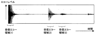
図2に超音波受信波の時間波形の例を示す。図2中、受信エコー領域(1)は、発信されたパルスが外壁4の中で多重反射したものを受信している領域である。また、受信エコー領域(2)は中間構造物5の表面からの反射された多重エコーであり、受信エコー領域(3)は測定対象物6から反射されたエコーである。
FIG. 2 shows an example of the time waveform of the ultrasonic reception wave. In FIG. 2, the reception echo area (1) is an area where a transmitted pulse is received by multiple reflection in the outer wall 4. The reception echo area (2) is a multiple echo reflected from the surface of the
したがって、測定対象物6に超音波が到達する時間を推定し、その時間領域の受信エコーをモニターし、受信エコー領域(3)にある測定対象物6からの受信波を検出し、解析する。
Therefore, the time for the ultrasonic wave to reach the
図3は、受信エコー領域(3)の超音波受信波の拡大図である。測定対象物6が超音波の伝播方向に振動している場合、超音波が測定対象物6に到達するまでの時間が振動量分だけ変化するため、受信波は受信波3aおよび受信波3bのように時間軸方向に移動した形状となる。超音波の発信を連続的に行い、受信波3a、3bを連続的に保存し、信号処理装置により受信波3a、3bの形状変化量を算出し、超音波の速度と掛け合わせることで、測定対象物6の振動量(変位量)を算出することができる。
FIG. 3 is an enlarged view of the ultrasonic reception wave in the reception echo area (3). When the
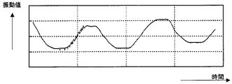
例えば、測定対象物6が水中にある場合を考える。水中での超音波の速度1500m/secとし、受信波の時間軸方向の変化量が10nsecとすると、1500(m/sec)×10(nsec)/2=7.5μmの振動を計測できたこととなる。その結果として図4に示すような振動の時間変化を得ることができる。この振動の時間変化から、検査対象6の振動の大きさ(振動値)及び振動周波数を検出し、それらの値の変動を監視することにより、検査対象の異常を把握することが可能となる。
For example, consider a case where the
また、図5に示すように、超音波送受信装置1として、送信用の超音波送信装置1aと受信用の超音波受信装置1bを別個に設けてもよい。これにより、送受信波の感度調整、雑音解析をそれぞれ別個に行うことができるので、精度の高い信号処理及び振動監視が可能となる。
As shown in FIG. 5, as the ultrasonic transmission /
本第1の実施形態によれば、容器等の構造物と測定対象物との間に内壁等の中間構造物が存在しても、中間構造物を伝播可能な周波数を有する超音波パルスを送受信波として用いることにより、高精度で測定対象物の振動を測定し、異常の発生の有無を監視することができる。 According to the first embodiment, even when an intermediate structure such as an inner wall exists between a structure such as a container and a measurement object, ultrasonic pulses having a frequency that can propagate through the intermediate structure are transmitted and received. By using it as a wave, it is possible to measure the vibration of the measurement object with high accuracy and to monitor the occurrence of abnormality.
(第2の実施形態)
本発明の第2の実施形態に係る振動監視装置を、図6〜図8を用いて説明する。
本発明の第2の実施形態は、本発明に係る監視装置をポンプ軸の監視又は熱交換機の伝熱管の監視に適用したものである。
(Second Embodiment)
A vibration monitoring apparatus according to a second embodiment of the present invention will be described with reference to FIGS.
In the second embodiment of the present invention, the monitoring device according to the present invention is applied to monitoring of a pump shaft or monitoring of a heat transfer tube of a heat exchanger.
図6(a)は揚水型の縦型ポンプの全体構成図で、長い揚水管の下端に羽根車を配置し、流体を吸い上げるものである。一般的にポンプに異常がないかどうか、振動監視による手法が用いられており、モータ部の加速度や回転部の軸振動が監視されている。この縦型ポンプは、図6(a)に示すように、揚水管10とポンプ軸12の間に上記の中間構造物5に相当する保護管11が設置されている。ポンプ軸12の振動を監視する場合、図6(a)の破線囲み部分を拡大して図6(b)に示すように、揚水管10の外側に超音波送受信装置1を設置し、内部にある保護管11を透過する超音波を発信することによりポンプ軸12の振動監視を行う。
FIG. 6A is an overall configuration diagram of a pumped-type vertical pump, in which an impeller is disposed at the lower end of a long pumped pipe to suck up a fluid. Generally, a vibration monitoring method is used to check whether there is any abnormality in the pump, and the acceleration of the motor unit and the shaft vibration of the rotating unit are monitored. In this vertical pump, as shown in FIG. 6A, a
本発明により外側から回転軸の監視が可能となることから、ポンプ本体の改造が不要でかつポンプの機能への影響を与えずにポンプの監視が可能となる。 According to the present invention, since the rotation shaft can be monitored from the outside, the pump main body is not required to be modified, and the pump can be monitored without affecting the function of the pump.
また、揚水管10がバレルやタンク内に設置されているタイプの縦型ポンプでは(図示せず)、バレルやタンクに超音波送受信装置1を設置し、中間構造物に相当する揚水管を通してポンプ軸12の振動監視を行うことも可能である。
In addition, in a vertical pump of a type in which the
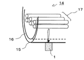
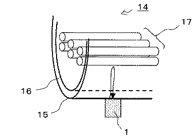
さらに、図7は熱交換器や給水加熱器のように伝熱管を持つ機器14の振動監視に本発明の振動監視装置を適用した場合を示す。伝熱管17を支える支え板の摩耗により伝熱管17の振動が増加し、伝熱管が破損にいたることがある。図8の例では、容器15と測定対象物である伝熱管17の間に邪魔板16が存在するが、外壁に設けた超音波送受信装置1により邪魔板16を伝播する超音波パルスを発信し、伝熱管17からの受信波を検出することにより伝熱管17の振動を監視する。
Further, FIG. 7 shows a case where the vibration monitoring device of the present invention is applied to vibration monitoring of a
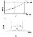
図8に振動監視の具体例を示す。検査対象物であるポンプ軸または伝熱管の振動の時間変化から、振動値及び振動周波数を検出し、それらの値の変動を監視する。そして、図8(a)に示すように、振動値が予め定められた判定基準を超えたときに異常が発生した判断する。また、振動周波数については、その周波数が正常時の周波数よりも所定値以上シフトしたときに異常が発生したと判断する。上記説明では、振動値及び振動周波数を、それぞれ別個に監視対象としているが、それらを組みわせてもよいことはもちろんである。 FIG. 8 shows a specific example of vibration monitoring. The vibration value and the vibration frequency are detected from the time change of the vibration of the pump shaft or the heat transfer tube, which is the inspection object, and the fluctuation of those values is monitored. Then, as shown in FIG. 8A, it is determined that an abnormality has occurred when the vibration value exceeds a predetermined determination criterion. Further, regarding the vibration frequency, it is determined that an abnormality has occurred when the frequency is shifted by a predetermined value or more than the normal frequency. In the above description, the vibration value and the vibration frequency are separately monitored, but it goes without saying that they may be combined.
また、本第2の実施形態では、本発明に係る振動監視装置をポンプまたは伝熱管の監視に適用した例を説明したが、検出対象物と超音波送受信装置1との間に中間構造物が存在する構造物であれば、全ての構造物に適用できることはもちろんである。
In the second embodiment, an example in which the vibration monitoring device according to the present invention is applied to monitoring of a pump or a heat transfer tube has been described. However, an intermediate structure is present between the detection object and the ultrasonic transmission /
本第2の実施形態によれば、本発明に係る振動監視装置を揚水ポンプや伝熱管を持つ機器、等に適用することにより、保護管や邪魔板等の中間構造物が存在したとしても、高精度でポンプ軸又は伝熱管の振動を監視し、確実に異常の発生を把握することができる。 According to the second embodiment, even if an intermediate structure such as a protective tube or a baffle plate is present by applying the vibration monitoring device according to the present invention to a device having a pumping pump or a heat transfer tube, etc., The vibration of the pump shaft or heat transfer tube can be monitored with high accuracy and the occurrence of an abnormality can be grasped reliably.
1…超音波送受新装置、1a…超音波発振装置、1b…超音波受信装置、2…送信波形、3…受信波形、3a,3b…受信波、4…外壁、5…中間構造物、6…測定対象物、10…揚水管、11…保護管、12…ポンプ軸、13…揚水ポンプ、14…機器、15…外壁、16…邪魔板、17…伝熱管。
DESCRIPTION OF
Claims (5)
前記構造物の外壁に設けられ測定対象物に超音波を発信し受信波を受信する超音波送受信装置と、受信波をデジタル値に変換するA/D変換装置と、前記デジタル値を演算処理し受信信号の時間波形形状の変化から測定対象物の振動変位を計測し、前記測定対象物の振動値と振動周波数を算出する信号処理装置と、前記振動値又は振動周波数の変化を監視することにより前記測定対象物の異常を判定する異常判定装置と、を備え、
前記超音波送受信装置は、当該超音波送受信装置から発信される超音波の周波数を変化させて受信波のエコーレベルが最大となる周波数を決定することによって、前記測定対象物に発信する超音波の波長を、nを整数としたとき前記中間構造物の厚さの2/n倍に設定することを特徴とする振動監視装置。 In a vibration monitoring apparatus for a structure having an intermediate structure between the structure and a measurement object in the structure,
An ultrasonic transmission / reception device that is provided on the outer wall of the structure and transmits an ultrasonic wave to a measurement object and receives a reception wave; an A / D conversion device that converts the reception wave into a digital value; By measuring the vibration displacement of the measurement object from the change of the time waveform shape of the received signal, calculating the vibration value and vibration frequency of the measurement object, and monitoring the change of the vibration value or vibration frequency An abnormality determination device for determining abnormality of the measurement object,
The ultrasonic transmission / reception device changes the frequency of the ultrasonic wave transmitted from the ultrasonic transmission / reception device and determines the frequency at which the echo level of the received wave is maximized, whereby the ultrasonic wave transmitted to the measurement object A vibration monitoring apparatus characterized in that the wavelength is set to 2 / n times the thickness of the intermediate structure when n is an integer .
前記構造物の外壁に設けられた超音波送受信装置から発信される超音波の周波数を変化させて受信波のエコーレベルが最大となる周波数を決定することによって、前記測定対象物に発信する超音波の波長を、nを整数としたとき前記中間構造物の厚さの2/n倍に設定するとともに、当該波長の超音波を前記測定対象物に発信し、受信波をデジタル値に変換し、前記デジタル値を演算処理し受信信号の時間波形形状の変化から測定対象物の振動変位を計測し、前記振動変位から前記測定対象物の振動値と振動周波数を算出し、前記振動値又は振動周波数の変化を監視することにより前記測定対象物の異常を判定することを特徴とする振動監視方法。 In the vibration monitoring method for a structure having an intermediate structure between the structure and the measurement object in the structure,
The ultrasonic wave transmitted to the measurement object by determining the frequency at which the echo level of the received wave is maximized by changing the frequency of the ultrasonic wave transmitted from the ultrasonic transmission / reception device provided on the outer wall of the structure. the wavelength of, and sets the 2 / n times the thickness of the intermediate structure where n is an integer, and transmits ultrasonic waves of the wavelength to the measurement object, converts the received waves into a digital value The digital value is processed, the vibration displacement of the measurement object is measured from the change in the time waveform shape of the received signal, the vibration value and vibration frequency of the measurement object are calculated from the vibration displacement, and the vibration value or vibration A vibration monitoring method, wherein abnormality of the measurement object is determined by monitoring a change in frequency.
Priority Applications (1)
| Application Number | Priority Date | Filing Date | Title |
|---|---|---|---|
| JP2008143083A JP5224912B2 (en) | 2008-05-30 | 2008-05-30 | Vibration monitoring apparatus and monitoring method |
Applications Claiming Priority (1)
| Application Number | Priority Date | Filing Date | Title |
|---|---|---|---|
| JP2008143083A JP5224912B2 (en) | 2008-05-30 | 2008-05-30 | Vibration monitoring apparatus and monitoring method |
Publications (2)
| Publication Number | Publication Date |
|---|---|
| JP2009288164A JP2009288164A (en) | 2009-12-10 |
| JP5224912B2 true JP5224912B2 (en) | 2013-07-03 |
Family
ID=41457509
Family Applications (1)
| Application Number | Title | Priority Date | Filing Date |
|---|---|---|---|
| JP2008143083A Active JP5224912B2 (en) | 2008-05-30 | 2008-05-30 | Vibration monitoring apparatus and monitoring method |
Country Status (1)
| Country | Link |
|---|---|
| JP (1) | JP5224912B2 (en) |
Families Citing this family (5)
| Publication number | Priority date | Publication date | Assignee | Title |
|---|---|---|---|---|
| CN103048040B (en) * | 2012-12-19 | 2015-07-08 | 中联重科股份有限公司 | Device, system and method for evaluating vibration of tail end of boom |
| CN104833413A (en) * | 2015-03-11 | 2015-08-12 | 国网浙江海盐县供电公司 | On-line vibration monitoring device used for transformer |
| KR101849099B1 (en) * | 2015-05-27 | 2018-04-16 | 금오공과대학교 산학협력단 | Boil and boil dry detection apparatus |
| CN106932088A (en) * | 2017-04-20 | 2017-07-07 | 北京微澄科技有限公司 | A kind of vibration monitoring methods, devices and systems of mobile article |
| CN115808236B (en) * | 2023-02-02 | 2023-05-05 | 武汉理工大学 | Marine turbocharger fault on-line monitoring and diagnosing method and device and storage medium |
Family Cites Families (6)
| Publication number | Priority date | Publication date | Assignee | Title |
|---|---|---|---|---|
| JPH0394109A (en) * | 1989-03-22 | 1991-04-18 | Mitsubishi Electric Corp | Ultrasonic measuring device |
| JP3038584B2 (en) * | 1991-11-21 | 2000-05-08 | ニスカ株式会社 | Ultrasonic object detection device |
| JPH08194059A (en) * | 1995-01-17 | 1996-07-30 | Kaijo Corp | Ultrasonic distance measuring apparatus |
| JP3782559B2 (en) * | 1997-10-23 | 2006-06-07 | 東京電力株式会社 | Reactor vibration monitoring device |
| JP2003042857A (en) * | 2001-08-03 | 2003-02-13 | Toshiba Corp | Ultrasonic temperature measuring apparatus |
| JP2004361131A (en) * | 2003-06-02 | 2004-12-24 | Shogo Tanaka | Method and device for measuring oscillation |
-
2008
- 2008-05-30 JP JP2008143083A patent/JP5224912B2/en active Active
Also Published As
| Publication number | Publication date |
|---|---|
| JP2009288164A (en) | 2009-12-10 |
Similar Documents
| Publication | Publication Date | Title |
|---|---|---|
| EP3115754B1 (en) | System and method for non-instrusive and continuous level measurement in a cylindrical vessel | |
| EP3115753B1 (en) | System and method for non-intrusive and continuous level measurement of a liquid | |
| EP3115755B1 (en) | System and method for measuring a speed of sound in a liquid or gaseous medium | |
| EP2799820B1 (en) | Liquid surface level measurement device, method, and program | |
| JP4686378B2 (en) | Pipe inspection device | |
| JPH07318336A (en) | Method and equipment to check pipeline with ultrasonic wave | |
| EP2029966A1 (en) | Acoustic method and system of measuring material loss from a solid structure, uses thereof and a software product | |
| EP2195611B1 (en) | Acoustic thickness measurements using gas as a coupling medium | |
| JP5224912B2 (en) | Vibration monitoring apparatus and monitoring method | |
| JP2009229355A (en) | Device and method for monitoring oscillation of nuclear reactor | |
| US8919193B2 (en) | Ultrasonic liquid level detector | |
| EP2343547A2 (en) | Torsional sensor, method thereof, and system for measurement of fluid parameters | |
| JP2010054434A (en) | Valve diagnostic method and valve diagnostic device | |
| EP3710795B1 (en) | Device and method for detecting deposition layers in a conduit conducting a liquid or a soft medium and/or for level detection | |
| JP2011027571A (en) | Piping thickness reduction inspection apparatus and piping thickness reduction inspection method | |
| US20090249879A1 (en) | Inspection systems and methods for detection of material property anomalies | |
| JP2008151705A (en) | Ultrasonic thickness measuring method and device | |
| CN106841385B (en) | Detection method based on sound-ultrasound polypropylene production pipeline powder coherent condition | |
| RU66029U1 (en) | INTEGRATED DEVICE FOR MEASURING FLOW, DENSITY AND VISCOSITY OF OIL PRODUCTS | |
| JP5318022B2 (en) | Structure vibration monitoring apparatus and monitoring method | |
| KR100989515B1 (en) | Pipe conduit block testing equipment using microprocessor and the method thereof | |
| JP2008107101A (en) | Nondestructive inspection method | |
| JP2006250595A (en) | Ultrasonic measuring method and device | |
| JP2001337077A (en) | Device for non-destructively inspecting exfoliation in concrete structure | |
| JP4674007B2 (en) | Liquid level measuring device in pipe and liquid level measuring method |
Legal Events
| Date | Code | Title | Description |
|---|---|---|---|
| A621 | Written request for application examination |
Free format text: JAPANESE INTERMEDIATE CODE: A621 Effective date: 20101220 |
|
| A977 | Report on retrieval |
Free format text: JAPANESE INTERMEDIATE CODE: A971007 Effective date: 20120607 |
|
| A131 | Notification of reasons for refusal |
Free format text: JAPANESE INTERMEDIATE CODE: A131 Effective date: 20120619 |
|
| A521 | Written amendment |
Free format text: JAPANESE INTERMEDIATE CODE: A523 Effective date: 20120810 |
|
| TRDD | Decision of grant or rejection written | ||
| A01 | Written decision to grant a patent or to grant a registration (utility model) |
Free format text: JAPANESE INTERMEDIATE CODE: A01 Effective date: 20130219 |
|
| A61 | First payment of annual fees (during grant procedure) |
Free format text: JAPANESE INTERMEDIATE CODE: A61 Effective date: 20130312 |
|
| R151 | Written notification of patent or utility model registration |
Ref document number: 5224912 Country of ref document: JP Free format text: JAPANESE INTERMEDIATE CODE: R151 |
|
| FPAY | Renewal fee payment (event date is renewal date of database) |
Free format text: PAYMENT UNTIL: 20160322 Year of fee payment: 3 |