JP5215376B2 - Liquid circulation device, liquid circulation control program, liquid ejection device - Google Patents
Liquid circulation device, liquid circulation control program, liquid ejection device Download PDFInfo
- Publication number
- JP5215376B2 JP5215376B2 JP2010289257A JP2010289257A JP5215376B2 JP 5215376 B2 JP5215376 B2 JP 5215376B2 JP 2010289257 A JP2010289257 A JP 2010289257A JP 2010289257 A JP2010289257 A JP 2010289257A JP 5215376 B2 JP5215376 B2 JP 5215376B2
- Authority
- JP
- Japan
- Prior art keywords
- pressure
- liquid
- circulation
- nozzle
- valve
- Prior art date
- Legal status (The legal status is an assumption and is not a legal conclusion. Google has not performed a legal analysis and makes no representation as to the accuracy of the status listed.)
- Expired - Fee Related
Links
- 239000007788 liquid Substances 0.000 title claims description 161
- 238000011084 recovery Methods 0.000 claims description 183
- 230000005499 meniscus Effects 0.000 claims description 32
- 239000000976 ink Substances 0.000 description 207
- 238000000034 method Methods 0.000 description 39
- 230000008569 process Effects 0.000 description 36
- 238000010586 diagram Methods 0.000 description 22
- 238000001514 detection method Methods 0.000 description 14
- 238000007599 discharging Methods 0.000 description 12
- 241001125929 Trisopterus luscus Species 0.000 description 11
- 230000007704 transition Effects 0.000 description 9
- 230000002093 peripheral effect Effects 0.000 description 8
- 230000001276 controlling effect Effects 0.000 description 7
- 238000011144 upstream manufacturing Methods 0.000 description 7
- 230000008859 change Effects 0.000 description 6
- 238000003860 storage Methods 0.000 description 6
- XLYOFNOQVPJJNP-UHFFFAOYSA-N water Substances O XLYOFNOQVPJJNP-UHFFFAOYSA-N 0.000 description 6
- 101001128814 Pandinus imperator Pandinin-1 Proteins 0.000 description 5
- 101001024685 Pandinus imperator Pandinin-2 Proteins 0.000 description 4
- 238000012423 maintenance Methods 0.000 description 4
- 238000010926 purge Methods 0.000 description 4
- 239000010409 thin film Substances 0.000 description 4
- 230000005856 abnormality Effects 0.000 description 3
- 239000010408 film Substances 0.000 description 3
- 239000006096 absorbing agent Substances 0.000 description 2
- 230000001133 acceleration Effects 0.000 description 2
- 230000004913 activation Effects 0.000 description 2
- 230000015572 biosynthetic process Effects 0.000 description 2
- 239000003086 colorant Substances 0.000 description 2
- 238000007872 degassing Methods 0.000 description 2
- 238000004519 manufacturing process Methods 0.000 description 2
- 230000035939 shock Effects 0.000 description 2
- 239000000758 substrate Substances 0.000 description 2
- 238000004140 cleaning Methods 0.000 description 1
- 230000014509 gene expression Effects 0.000 description 1
- 239000011521 glass Substances 0.000 description 1
- 230000005484 gravity Effects 0.000 description 1
- 239000002184 metal Substances 0.000 description 1
- 238000012544 monitoring process Methods 0.000 description 1
- 230000009467 reduction Effects 0.000 description 1
- 230000001105 regulatory effect Effects 0.000 description 1
- 229910000679 solder Inorganic materials 0.000 description 1
- 239000002904 solvent Substances 0.000 description 1
Images


Classifications
-
- B—PERFORMING OPERATIONS; TRANSPORTING
- B41—PRINTING; LINING MACHINES; TYPEWRITERS; STAMPS
- B41J—TYPEWRITERS; SELECTIVE PRINTING MECHANISMS, i.e. MECHANISMS PRINTING OTHERWISE THAN FROM A FORME; CORRECTION OF TYPOGRAPHICAL ERRORS
- B41J2/00—Typewriters or selective printing mechanisms characterised by the printing or marking process for which they are designed
- B41J2/005—Typewriters or selective printing mechanisms characterised by the printing or marking process for which they are designed characterised by bringing liquid or particles selectively into contact with a printing material
- B41J2/01—Ink jet
- B41J2/17—Ink jet characterised by ink handling
- B41J2/175—Ink supply systems ; Circuit parts therefor
-
- B—PERFORMING OPERATIONS; TRANSPORTING
- B41—PRINTING; LINING MACHINES; TYPEWRITERS; STAMPS
- B41J—TYPEWRITERS; SELECTIVE PRINTING MECHANISMS, i.e. MECHANISMS PRINTING OTHERWISE THAN FROM A FORME; CORRECTION OF TYPOGRAPHICAL ERRORS
- B41J2/00—Typewriters or selective printing mechanisms characterised by the printing or marking process for which they are designed
- B41J2/005—Typewriters or selective printing mechanisms characterised by the printing or marking process for which they are designed characterised by bringing liquid or particles selectively into contact with a printing material
- B41J2/01—Ink jet
- B41J2/17—Ink jet characterised by ink handling
- B41J2/18—Ink recirculation systems
-
- B—PERFORMING OPERATIONS; TRANSPORTING
- B41—PRINTING; LINING MACHINES; TYPEWRITERS; STAMPS
- B41J—TYPEWRITERS; SELECTIVE PRINTING MECHANISMS, i.e. MECHANISMS PRINTING OTHERWISE THAN FROM A FORME; CORRECTION OF TYPOGRAPHICAL ERRORS
- B41J2202/00—Embodiments of or processes related to ink-jet or thermal heads
- B41J2202/01—Embodiments of or processes related to ink-jet heads
- B41J2202/12—Embodiments of or processes related to ink-jet heads with ink circulating through the whole print head
Landscapes
- Ink Jet (AREA)
Description
本発明は、液体循環装置、液体循環制御プログラムおよび液体吐出装置に関する。 The present invention relates to a liquid circulation device, a liquid circulation control program, and a liquid ejection device.
液体吐出部のノズルから吐出される液体(インク)を循環させる液体循環装置として、例えば、下記特許文献1,2記載の装置が知られている。
As a liquid circulation device that circulates the liquid (ink) discharged from the nozzle of the liquid discharge portion, for example, devices described in
特許文献1には、上流側インクタンクと、一端側が上流側インクタンクに接続された上流側インク流路と、上流側インク流路の他端側に接続され、インクを吐出するノズルに通じるノズル分岐部と、一端側がノズル分岐部に接続された下流側インク流路と、下流側インク流路の他端側に接続された上流側インクタンクから流出したインクを蓄える下流側インクタンクと、下流側インクタンクのインクを上流側インクタンクに戻す帰還流路と、を有する液体循環装置が開示されている。 Patent Document 1 discloses an upstream ink tank, an upstream ink channel whose one end is connected to the upstream ink tank, and a nozzle connected to the other end of the upstream ink channel and leading to a nozzle for discharging ink. A branching portion, a downstream ink channel whose one end is connected to the nozzle branching portion, a downstream ink tank for storing ink flowing out from the upstream ink tank connected to the other end of the downstream ink channel, and a downstream A liquid circulation device having a return flow path for returning the ink of the side ink tank to the upstream side ink tank is disclosed.
特許文献2には、ノズル面からインクを吐出するインクヘッドと、貯留されたインクの液面がインクヘッドのノズル面と同等、又は重力方向上方となるように配置された大気と連がる、又は遮断可能な第一のタンクと、貯留されたインクの液面がインクヘッドのノズル面より重力方向下方となるように配置された大気と連がる、又は遮断可能な第二のタンクと、第二のタンク内のインクを第一のタンクへと送液するポンプと、第二のタンクを大気に対して遮断した際に、第二のタンク内の圧力を一定の負圧状態に維持させる圧力調整部と、を有する液体循環装置が開示されている。
In
ノズルに対する液体循環開始時において、ノズルに掛かる圧力の変動を抑制するようにした液体循環装置を提供することを課題とする。 It is an object of the present invention to provide a liquid circulation device that suppresses fluctuations in pressure applied to a nozzle at the start of liquid circulation to the nozzle.
本発明の請求項1の液体循環装置は、液体を吐出するためのノズルを有する液体吐出部と、液体を前記液体吐出部に供給する供給流路と、液体を前記液体吐出部から回収する回収流路と、前記供給流路の液体の圧力を調整する第1圧力調整手段と、前記回収流路の液体の圧力を調整する第2圧力調整手段と、前記供給流路および前記回収流路の少なくとも一方の流路に設けられ、該流路を開閉する開閉弁と、前記第1圧力調整手段、前記第2圧力調整手段および前記開閉弁を制御し、前記ノズルにおいて液体をメニスカス保持しつつ、前記ノズルに対して供給側の液体の圧力と回収側の液体の圧力とに循環時差圧を生じさせて液体を循環させると共に、前記ノズルに対する液体の循環を開始するとき、前記開閉弁を閉止した状態で前記供給流路の液体の圧力と前記回収流路の液体の圧力との差圧を前記循環時差圧よりも小さくするように前記第1圧力調整手段および前記第2圧力調整手段を駆動し、次いで前記開閉弁を開放し、次いで前記差圧を前記循環時差圧へと徐々に変化させる循環制御手段と、を備えることを特徴とする。 According to a first aspect of the present invention, there is provided a liquid circulation apparatus including a liquid discharge section having a nozzle for discharging a liquid, a supply flow path for supplying liquid to the liquid discharge section, and a recovery for recovering liquid from the liquid discharge section. A flow path, a first pressure adjusting means for adjusting the pressure of the liquid in the supply flow path, a second pressure adjusting means for adjusting the pressure of the liquid in the recovery flow path, and the supply flow path and the recovery flow path An opening / closing valve provided in at least one of the flow paths, and controlling the first pressure adjusting means , the second pressure adjusting means, and the open / close valve, and holding the liquid at the nozzle while maintaining the meniscus, A circulation time differential pressure is generated between the supply-side liquid pressure and the recovery-side liquid pressure with respect to the nozzle to circulate the liquid, and the on-off valve is closed when the liquid circulation to the nozzle is started. The supply flow in the state The differential pressure between the pressure and the pressure of liquid in the recovery flow path of the liquid to drive the first pressure regulating means and said second pressure adjusting means so as to be smaller than the circulation time difference pressure, then the on-off valve And a circulation control means that opens and then gradually changes the differential pressure to the differential pressure during circulation.
本発明の請求項2の液体循環装置は、請求項1に記載の液体循環装置において、前記循環制御手段は、前記ノズルに対する液体の循環を開始するとき、前記開閉弁を閉止した状態で前記供給流路の液体の圧力と前記回収流路の液体の圧力とをそれぞれ、前記ノズルにおいて液体をメニスカス保持可能な圧力範囲の圧力に制御することを特徴とする。 The liquid circulation device according to a second aspect of the present invention is the liquid circulation device according to the first aspect, wherein the circulation control means closes the on-off valve when the circulation control means starts the circulation of the liquid to the nozzle. The pressure of the liquid in the flow path and the pressure of the liquid in the recovery flow path are each controlled to a pressure in a pressure range in which the liquid can be held in the meniscus at the nozzle.
本発明の請求項3の液体循環装置は、請求項2に記載の液体循環装置において、前記開閉弁は、開放されるときに前記ノズルに対して圧力変動を生じさせるものであり、前記循環制御手段は、前記ノズルに対する液体の循環を開始するとき、前記開閉弁を閉止した状態で前記供給流路の液体の圧力と前記回収流路の液体の圧力とをそれぞれ、前記ノズルにおいて液体をメニスカス保持可能な圧力範囲の中央値に対して開放弁の圧力変動を相殺する方向の圧力に制御することを特徴とする。 A liquid circulation device according to a third aspect of the present invention is the liquid circulation device according to the second aspect, wherein the on-off valve causes a pressure fluctuation with respect to the nozzle when opened, and the circulation control When the liquid circulation to the nozzle is started, the liquid pressure in the supply flow path and the liquid pressure in the recovery flow path are held in the nozzle with the meniscus held in a state where the on-off valve is closed. It is characterized by controlling the pressure in a direction that cancels out the pressure fluctuation of the open valve with respect to the median of the possible pressure range.
本発明の請求項4の液体循環装置は、請求項1〜3のいずれか1項に記載の液体循環装置において、さらに、前記供給流路と前記回収流路に接続され、前記液体吐出部を迂回する迂回流路と、前記迂回流路に設けられ、前記迂回流路を開閉する迂回流路開閉弁と、を備え、前記循環制御手段は、前記ノズルに対する液体の循環を開始するとき、前記開閉弁を開放するのに同期して前記迂回流路開閉弁を開放することを特徴とする。 The liquid circulation device according to a fourth aspect of the present invention is the liquid circulation device according to any one of the first to third aspects, further connected to the supply flow channel and the recovery flow channel, A detour flow path for detouring, and a detour flow path opening / closing valve provided in the detour flow path for opening and closing the detour flow path, wherein the circulation control means starts the circulation of the liquid to the nozzle, The bypass flow path opening / closing valve is opened in synchronization with opening of the opening / closing valve.
本発明の請求項5の液体循環装置は、請求項1〜4のいずれか1項に記載の液体循環装置において、前記循環制御手段は、前記ノズルに対する液体の循環を終了するとき、前記開閉弁を開放した状態で前記供給流路の液体の圧力と前記回収流路の液体の圧力との差圧を前記循環時差圧よりも小さい差圧へと徐々に変化させ、次いで前記開閉弁を閉止することを特徴とする。 The liquid circulation device according to a fifth aspect of the present invention is the liquid circulation device according to any one of the first to fourth aspects, wherein the circulation control means has the on-off valve when the circulation of the liquid to the nozzle is terminated. The pressure difference between the liquid pressure in the supply flow path and the liquid pressure in the recovery flow path is gradually changed to a pressure difference smaller than the circulating pressure difference, and then the on-off valve is closed. It is characterized by that.
本発明の請求項6の液体循環装置は、請求項5に記載の液体循環装置において、前記循環制御手段は、前記ノズルに対する液体の循環を終了するとき、前記開閉弁を開放した状態で前記供給流路の液体の圧力と前記回収流路の液体の圧力とをそれぞれ、前記ノズルにおいて液体をメニスカス保持可能な圧力範囲の圧力に制御することを特徴とする。 The liquid circulation device according to a sixth aspect of the present invention is the liquid circulation device according to the fifth aspect, wherein the circulation control means opens the supply with the on-off valve opened when the circulation of the liquid to the nozzle is finished. The pressure of the liquid in the flow path and the pressure of the liquid in the recovery flow path are each controlled to a pressure in a pressure range in which the liquid can be held in the meniscus at the nozzle.
本発明の請求項7の液体循環装置は、請求項6に記載の液体循環装置において、前記開閉弁は、閉止されるときに前記ノズルに対して圧力変動を生じさせるものであり、前記循環制御手段は、前記ノズルに対する液体の循環を終了するとき、前記開閉弁を開放した状態で前記供給流路の液体の圧力と前記回収流路の液体の圧力とをそれぞれ、前記ノズルにおいて液体をメニスカス保持可能な圧力範囲の中央値に対して開放弁の圧力変動を相殺する方向の圧力に制御することを特徴とする。 A liquid circulation device according to a seventh aspect of the present invention is the liquid circulation device according to the sixth aspect, wherein the on-off valve causes a pressure fluctuation with respect to the nozzle when closed, and the circulation control When the liquid circulation to the nozzle ends, the means holds the liquid pressure in the supply flow path and the liquid pressure in the recovery flow path in a state where the on-off valve is opened, and holds the liquid at the nozzle. It is characterized by controlling the pressure in a direction that cancels out the pressure fluctuation of the open valve with respect to the median of the possible pressure range.
本発明の請求項8の液体循環装置は、請求項1〜4のいずれか1項に記載の液体循環装置において、前記開閉弁は、前記供給流路および前記回収流路のそれぞれの流路に設けられ、前記循環制御手段は、前記ノズルに対して液体を循環させているとき、前記供給流路および前記回収流路の少なくとも一方の液体の圧力を前記ノズルにおいて液体をメニスカス保持可能な圧力範囲の圧力に制御すると共に、前記ノズルに対する液体の循環を終了するとき、前記供給流路および前記回収流路の他方に設けられた前記開閉弁を閉止することを特徴とする。 The liquid circulation device according to an eighth aspect of the present invention is the liquid circulation device according to any one of the first to fourth aspects, wherein the on-off valve is provided in each of the supply flow channel and the recovery flow channel. A pressure range in which the pressure of the liquid in at least one of the supply flow path and the recovery flow path can be maintained at the nozzle when the liquid is circulated to the nozzle. When the circulation of the liquid to the nozzle is finished, the on-off valve provided on the other of the supply channel and the recovery channel is closed.
本発明の請求項9の液体循環装置は、請求項8に記載の液体循環装置において、前記開閉弁を動作させるための電力を供給する非常用電源を備えることを特徴とする。 A liquid circulation device according to a ninth aspect of the present invention is the liquid circulation device according to the eighth aspect, further comprising an emergency power supply for supplying electric power for operating the on-off valve.
本発明の請求項10の液体循環制御プログラムは、コンピュータを、請求項1〜9のいずれか1項に記載の液体循環装置の循環制御手段として実行させることを特徴とする。 A liquid circulation control program according to a tenth aspect of the present invention causes a computer to be executed as the circulation control means of the liquid circulation device according to any one of the first to ninth aspects.
本発明の請求項11の液体吐出装置は、請求項1〜9のいずれか1項に記載の液体循環装置によって前記ノズルに対して循環される液体を前記ノズルから吐出させることを特徴とする。 A liquid ejection device according to an eleventh aspect of the present invention is characterized in that the liquid circulated to the nozzle is ejected from the nozzle by the liquid circulation device according to any one of the first to ninth aspects.
本発明の請求項1に記載の液体循環装置によれば、ノズルに対する液体循環開始時において、供給側圧力と回収側圧力とに循環時差圧が生じている状態で開閉弁を開放する場合に比べて、ノズルに掛かる圧力の変動を抑制することができる。 According to the liquid circulation device of the first aspect of the present invention, compared to the case where the on-off valve is opened when the circulation pressure difference is generated between the supply side pressure and the recovery side pressure at the start of liquid circulation to the nozzle. Thus, fluctuations in pressure applied to the nozzle can be suppressed.
本発明の請求項2に記載の液体循環装置によれば、ノズルに対する液体循環開始時において、開閉弁を開放したとき、ノズルにおいて液体をメニスカス保持可能であり、ノズルからの液体漏れやノズルへの気泡進入を抑制することができる。 According to the liquid circulation device of the second aspect of the present invention, when the on-off valve is opened at the start of liquid circulation to the nozzle, the liquid can be held in the meniscus at the nozzle, and liquid leakage from the nozzle or leakage to the nozzle can be achieved. Bubble entry can be suppressed.
本発明の請求項3に記載の液体循環装置によれば、ノズルに対する液体循環開始時において、開閉弁を開放する際にノズルに対して圧力変動を生じさせる構成において、ノズルにおいて液体をメニスカス保持でき、ノズルからの液体漏れやノズルへの気泡進入を抑制することができる。 According to the liquid circulation device of the third aspect of the present invention, when the liquid circulation to the nozzle is started, the liquid can be held in the meniscus at the nozzle in the configuration in which the pressure fluctuation is caused to the nozzle when the on-off valve is opened. , It is possible to suppress liquid leakage from the nozzle and entry of bubbles into the nozzle.
本発明の請求項4に記載の液体循環装置によれば、ノズルに対する液体循環開始時において、迂回流路開閉弁を同期して開放しない場合に比べて、ノズルからの液体漏れやノズルからの気泡進入を抑制することができる。 According to the liquid circulation device of the fourth aspect of the present invention, at the time of starting the liquid circulation to the nozzle, the liquid leakage from the nozzle and the bubbles from the nozzle are compared with the case where the bypass flow path opening / closing valve is not opened synchronously. Ingress can be suppressed.
本発明の請求項5に記載の液体循環装置によれば、ノズルに対する液体循環終了時において、供給側圧力と回収側圧力とに循環時差圧が生じている状態で開閉弁を閉止する場合に比べて、ノズルに掛かる圧力の変動を抑制することができる。 According to the liquid circulation device of the fifth aspect of the present invention, compared to the case where the on-off valve is closed when the circulation of pressure between the supply side pressure and the recovery side pressure occurs at the end of the liquid circulation to the nozzle. Thus, fluctuations in pressure applied to the nozzle can be suppressed.
本発明の請求項6に記載の液体循環装置によれば、ノズルに対する液体循環終了時において、ノズルにおいて液体をメニスカス保持でき、ノズルからの液体漏れやノズルへの気泡進入を抑制することができる。 According to the liquid circulation device of the sixth aspect of the present invention, the liquid can be held in the meniscus at the end of the liquid circulation to the nozzle, and the liquid leakage from the nozzle and the bubble intrusion to the nozzle can be suppressed.
本発明の請求項7に記載の液体循環装置によれば、ノズルに対する液体循環終了時において、開閉弁を閉止する際にノズルに対して圧力変動を生じさせる構成において、ノズルにおいて液体をメニスカス保持でき、ノズルからの液体漏れやノズルへの気泡進入を抑制することができる。 According to the liquid circulation device of the seventh aspect of the present invention, when the liquid circulation to the nozzle is finished, the liquid can be held in the nozzle at the meniscus in the configuration in which the pressure fluctuation is caused to the nozzle when the on-off valve is closed. , It is possible to suppress liquid leakage from the nozzle and entry of bubbles into the nozzle.
本発明の請求項8に記載の液体循環装置によれば、ノズルに対する液体循環終了時において、ノズルにおいて液体をメニスカス保持でき、ノズルからの液体漏れやノズルへの気泡進入を抑制することができる。 According to the liquid circulation device of the eighth aspect of the present invention, the liquid can be held in the meniscus at the end of the liquid circulation to the nozzle, and the liquid leakage from the nozzle and the bubble intrusion to the nozzle can be suppressed.
本発明の請求項9に記載の液体循環装置によれば、停電など異常時においても開閉弁を閉止でき、ノズルからの液体漏れやノズルからの気泡進入を抑制することができる。 According to the liquid circulation device of the ninth aspect of the present invention, the on-off valve can be closed even when an abnormality such as a power failure occurs, and liquid leakage from the nozzle and entry of bubbles from the nozzle can be suppressed.
本発明の請求項10に記載の液体循環制御プログラムによれば、循環制御手段をソフトウェアで実現することができる。 According to the liquid circulation control program of the tenth aspect of the present invention, the circulation control means can be realized by software.
本発明の請求項11に記載の液体吐出装置によれば、常にフレッシュな液体をノズルから吐出することができる。 According to the liquid ejecting apparatus of the eleventh aspect of the present invention, it is possible to always eject fresh liquid from the nozzle.
(全体構成)
本実施の形態では、液滴を吐出する液滴吐出装置の一例として、インク滴を吐出して記録媒体に画像を記録するインクジェット記録装置について説明する。
(overall structure)
In this embodiment, as an example of a droplet discharge device that discharges droplets, an ink jet recording device that discharges ink droplets and records an image on a recording medium will be described.
なお、液滴吐出装置としては、インクジェット記録装置に限定されるものではない。液滴吐出装置としては、例えば、フィルムやガラス上にインク等を吐出してカラーフィルタを製造するカラーフィルタ製造装置、有機EL溶液を基板上に吐出してELディスプレイパネルを形成する装置、溶解状態の半田を基板上に吐出して部品実装用のバンプを形成する装置、金属を含む液体を吐出して配線パターンを形成する装置及び液滴を吐出して膜を形成する各種の成膜装置であってもよく、液滴を吐出するものであればよい。 Note that the droplet discharge device is not limited to the ink jet recording device. As a droplet discharge device, for example, a color filter manufacturing device for manufacturing a color filter by discharging ink or the like on a film or glass, a device for forming an EL display panel by discharging an organic EL solution onto a substrate, a dissolved state A device for forming a bump for mounting components by discharging a solder on a substrate, a device for forming a wiring pattern by discharging a liquid containing metal, and various film forming devices for forming a film by discharging a droplet It may be present as long as it ejects droplets.
図17は、本実施の形態に係るインクジェット記録装置の構成を示す概略図である。 FIG. 17 is a schematic diagram showing the configuration of the ink jet recording apparatus according to the present embodiment.
図17に示すように、インクジェット記録装置1010は、用紙等の記録媒体Pが収容される記録媒体収容部1012と、記録媒体Pに画像を記録する画像記録部1014と、記録媒体収容部1012から画像記録部1014へ記録媒体Pを搬送する搬送手段1016と、画像記録部1014によって画像が記録された記録媒体Pが排出される記録媒体排出部1018と、を備えている。
As shown in FIG. 17, the
画像記録部1014は、液滴を吐出する液滴吐出ヘッドの一例として、インク滴を吐出して記録媒体に画像を記録するインクジェットヘッド10Y、10M、10C、10K(以下、10Y〜10Kと示す)を備えている。
The
また、インクジェットヘッド10Y〜10Kは、ノズル11(図4参照)が形成されたノズル面1022Y〜1022Kをそれぞれ有している。このノズル面1022Y〜1022Kは、インクジェット記録装置1010での画像記録が想定される記録媒体Pの最大幅と同程度か、又はそれ以上の記録可能領域を有している。
Further, the inkjet heads 10Y to 10K have
さらに、インクジェットヘッド10Y〜10Kは、記録媒体Pの搬送方向の下流側から、イエロー(Y)、マゼンタ(M)、シアン(C)、ブラック(K)の色の順で並列に並べられており、その各色に対応したインク滴を、圧電方式によって、複数のノズル11から吐出し、画像を記録する構成となっている。なお、インクジェットヘッド10Y〜10Kにおいて、インク滴を吐出させる構成は、サーマル方式等の他の方式によって吐出させる構成であっても良い。
Furthermore, the inkjet heads 10Y to 10K are arranged in parallel in the order of yellow (Y), magenta (M), cyan (C), and black (K) from the downstream side in the conveyance direction of the recording medium P. The ink droplets corresponding to the respective colors are ejected from the plurality of
インクジェット記録装置1010には、液体を貯留する貯留部として、各色のインクを貯留するインクタンク1021Y、1021M、1021C、1021K(以下、1021Y〜1021Kと示す)が設けられている。このインクタンク1021Y〜1021Kから、各インクジェットヘッド10Y〜10Kへインクが供給される。なお、インクジェットヘッド10Y〜10Kへ供給されるインクとしては、水性インク、油性インク、溶剤系インク等、各種インクの使用が可能である。
The ink
搬送手段1016は、記録媒体収容部1012内の記録媒体Pを1枚ずつ取り出す取出ドラム1024と、画像記録部1014のインクジェットヘッド10Y〜10Kへ記録媒体Pを搬送しその記録面(表面)をインクジェットヘッド10Y〜10Kに対面させる搬送体としての搬送ドラム1026と、画像が記録された記録媒体Pを記録媒体排出部1018へ送り出す送出ドラム1028と、を有している。そして、取出ドラム1024、搬送ドラム1026、送出ドラム1028は、それぞれ記録媒体Pがその周面に静電的吸着手段、或いは吸引や粘着などの非静電的吸着手段によって保持されるように構成されている。
The conveying means 1016 conveys the recording medium P to the take-
また、取出ドラム1024、搬送ドラム1026、送出ドラム1028には、それぞれ記録媒体Pの搬送方向下流側端部を挟んで保持する保持手段としてのグリッパー1030が、例えば2組ずつ備えられており、これら3個のドラム1024、1026、1028は、それぞれその周面に記録媒体Pを、グリッパー1030によってこの場合は2枚まで保持可能に構成されている。そして、グリッパー1030は、各ドラム1024、1026、1028の周面に2つずつ形成された凹部1024A、1026A、1028A内に設けられている。
Further, each of the take-
具体的には、各ドラム1024、1026、1028の凹部1024A、1026A、1028A内の予め定められた位置に、各ドラム1024、1026、1028の回転軸1032に沿って回転軸1034が支持されており、この回転軸1034には、その軸方向に間隔をおいて複数のグリッパー1030が固定されている。したがって、回転軸1034が、図示しないアクチュエーターによって正逆両方向に回転することにより、グリッパー1030が各ドラム1024、1026、1028の周方向に沿って正逆両方向に回転し、記録媒体Pの搬送方向下流側端部を挟んで保持したり、離したりするようになっている。
Specifically, the
つまり、グリッパー1030は、その先端部が各ドラム1024、1026、1028の周面から若干突出するように回転することで、取出ドラム1024の周面と搬送ドラム1026の周面とが対面する受渡位置1036において、取出ドラム1024のグリッパー1030から搬送ドラム26のグリッパー1030へ記録媒体Pを受け渡すようになっており、搬送ドラム1026の周面と送出ドラム1028の周面とが対面する受渡位置1038において、搬送ドラム1026のグリッパー1030から送出ドラム1028のグリッパー1030へ記録媒体Pを受け渡すようになっている。
That is, the
また、インクジェット記録装置1010は、インクジェットヘッド10Y〜10Kをメンテナンスするメンテナンスユニット(図示省略)を備えている。メンテナンスユニットは、インクジェットヘッド10Y〜10Kのノズル面を覆うキャップ、予備吐出(空吐出)された液滴を受ける受け部材、ノズル面を清掃する清掃部材、ノズル11内のインクを吸引するための吸引装置等を有しており、メンテナンスユニットがインクジェットヘッド10Y〜10Kに対向する対向位置に移動し、各種のメンテナンスを行う。
Further, the ink
次に、インクジェット記録装置1010の画像記録動作について説明する。
Next, an image recording operation of the
記録媒体収容部1012から取出ドラム1024のグリッパー1030により1枚ずつ取り出されて保持された記録媒体Pは、取出ドラム1024の周面に吸着されつつ搬送され、受渡位置1036において、取出ドラム1024のグリッパー1030から搬送ドラム1026のグリッパー1030へ受け渡される。
The recording medium P taken out and held one by one by the
搬送ドラム1026のグリッパー1030により保持された記録媒体Pは、その搬送ドラム26に吸着されつつインクジェットヘッド10Y〜10Kの画像記録位置まで搬送され、そのインクジェットヘッド10Y〜10Kから吐出されるインク滴により、記録面に画像が記録される。
The recording medium P held by the
記録面に画像が記録された記録媒体Pは、受渡位置1038において、搬送ドラム1026のグリッパー1030から送出ドラム1028のグリッパー1030へ受け渡される。そして、送出ドラム1028のグリッパー1030により保持された記録媒体Pは、その送出ドラム1028に吸着されつつ搬送され、記録媒体排出部1018へ排出される。以上のように、一連の画像記録動作が行われる。
The recording medium P on which an image is recorded on the recording surface is delivered from the
(配管構成)
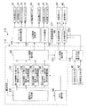
図1には、本実施の形態に係るインクジェット記録装置1010のインクジェットヘッド10の配管図が示されている。尚、図1に示す配管図は各色のインクのうちの1色、例えばイエローについてのものである。他の色のインクの配管構成も同様である。
(Piping configuration)
FIG. 1 shows a piping diagram of an
本実施の形態のインクジュットヘッド10には、複数の液体吐出部(以下、「ヘッドモジュール」という)12が取り付けられ、それぞれのヘッドモジュール12へ均等(一定の圧力、一定の流量)にインクを供給するためのインク循環用配管路が形成されている。
A plurality of liquid ejection units (hereinafter referred to as “head modules”) 12 are attached to the
図1に示される如く、ヘッドモジュール12には、インクが流入する入力ポート12Aと、インクを排出する出力ポート12Bとが設けられている。入力ポート12Aには、供給側マニホールド14から分岐した供給側分岐管16の先端が取り付けられ、出力ポート12Bには、回収側マニホールド18から分岐した回収側分岐管20の先端が取り付けられている。すなわち、供給側マニホールド14及び回収側マニホールド18には、ヘッドモジュール12の設置数分の分岐管(供給側分岐管16及び回収側分岐管20)が設けられ、供給側マニホールド14に供給されるインクを予め定められた圧力Pin、かつ予め定められた流量でそれぞれのヘッドモジュール12へ供給し、さらには、ヘッドモジュール12へ供給されたインクを予め定められた圧力Pout、かつ予め定められた流量でそれぞれヘッドモジュール12から回収側マニホールド18へ回収する構造となっている。
As shown in FIG. 1, the
すなわち、供給側マニホールド14の圧力Pinと回収側マニホールド18の圧力Poutにより、ヘッドモジュール12部で差圧ΔPを発生させ、この結果、ヘッドモジュール12内では、入力ポート12Aと出力ポート12Bの間にインクの流れが生じ、この流れにより、常にフレッシュなインクがヘッドモジュール12に供給されることになる。インク吐出口であるノズル面には、当該供給側マニホールド14の圧力Pinと回収側マニホールド18の圧力Poutに依存する背圧Pnzlが付与されている。背圧Pnzlについての詳細は後述する。
That is, a differential pressure ΔP is generated in the
供給側分岐管16にはそれぞれ、開閉弁の一例としての供給側バルブ22と緩衝器24とが介在されている。また、回収側分岐管20にはそれぞれ、開閉弁の一例としての回収側バルブ26と緩衝器24とが介在されている。供給側バルブ22及び回収側バルブ26は、ヘッドモジュール12を個別に動作させる必要があるときに開閉操作されるものであると共に、後述するようにヘッドモジュール12へのインクの循環を開始する際あるいは終了する際に開閉操作されるものである。緩衝器24は、供給側マニホールド14から供給されるインク、或いは回収側マニホールド18へ回収されるインクの流動時の圧力変動等を緩和する役目を有している。
A
供給側マニホールド14は、その長手方向一端部(図1の右端部)にインク循環配管系の供給管28の一端部が取り付けられ、一方回収側マニホールド18は、その長手方向一端部(図1の右端部)にインク循環配管系の回収管30の一端部が取り付けられている。
The
また、供給側マニホールド14と回収側マニホールド18のそれぞれの他端部(図1の左端部)の間には、第1のバイパス流路32と迂回流路の一例としての第2のバイパス流路34とが設けられている。第1のバイパス流路32には、第1のバイパスバルブ36が介在されている。また、第2のバイパス流路34には、迂回流路開閉弁の一例としての第2のバイパスバルブ38が介在されている。この第1のバイパス流路32及び第2のバイパス流路34は、供給側マニホールド14と回収側マニホールド18との間の圧力、流量調整等に用いられる。例えば、後述の第1の循環時(供給側マニホールド14から回収側マニホールド18への流れ)は、第1のバイパスバルブ36が閉止、第2のバイパスバルブ38が開放されており、第2のバイパス流路38のみが通じている。
In addition, a
さらに、供給側マニホールド14と回収側マニホールド18の他端部には、それぞれ供給側圧力センサ40及び回収側圧力センサ42が取り付けられており、供給側マニホールド14と回収側マニホールド18内のインクの圧力を監視している。
Further, a supply-
供給側マニホールド14に連結された供給管28の他端部は、供給側サブタンク44に連結されている。供給側サブタンク44は、二室構造で、弾性力を有する薄膜部材44Aで仕切られており、その1つがインク用サブタンク室44B、他の1つが空気室44Cとなっている。
The other end of the
インク用サブタンク室44Bには、インクをバッファタンク46から引き込む(およびバッファタンク46へ回収する)ための供給側主管48の一端部が連結されている。供給側主管48の他端の開口はバッファタンク46に貯留されたインクに浸漬されている。
One end of a supply-side main pipe 48 for drawing ink from the buffer tank 46 (and collecting it into the buffer tank 46) is connected to the ink
供給側主管48には、バッファタンク46から供給側サブタンク44にかけて順番に、脱気モジュール50、一方向弁52、第1圧力調整手段の一例としての供給側ポンプ54、供給側フィルタ56、インク温度調整器58がそれぞれ介在されており、供給側ポンプ54の駆動力で、バッファタンク46に貯留されているインクを供給側サブタンク44へ供給する途中で、インク内から気泡を取り除き、かつインクの温度を管理している。
The supply side main pipe 48 includes a
なお、供給側ポンプ54の入側は、供給主管48とは別に分岐管53の一端部が接続され、この分岐管53の他方の開口は、一方向弁55を介して、バッファタンク46に貯留されたインクに浸漬されている。
The inlet side of the
また、本実施の形態で適用される供給側ポンプ54は、ステッピングモータを用いたチューブポンプ(弾性力を持つチューブをステッピングモータによる回転駆動でしごきながらチューブ内のインクを供給する)であるが、特にこのような圧力調整手段(ポンプ)に限定されるものではない。要は、回転を正逆転させることで、供給側のインクの圧力を高圧側および低圧側に調整できるものであればよい。なお、以下で、ポンプの駆動回転数を示す場合、ステッピングモータの回転数と同等とする。
Further, the supply-
供給側サブタンク44の空気室44Cには、開放管60が取り付けられている。開放管60には、供給側エアバルブ66が介在されている。
An
また、インク用サブタンク室44Bは、ドレイン管68の一端が連結されている。ドレイン管68の他端の開口は、バッファタンク46に貯留されたインクに浸漬されている。ドレイン管68には、供給側ドレインバルブ70が介在されている。
The ink sub-tank
供給側サブタンク44は、空気室44Cと薄膜部材44Aにより、インク用サブタンク室44B内の圧力を所望の値に調整・維持する役目を有している。
The supply-
一方、回収側マニホールド18に連結された回収管30の他端部は、回収側サブタンク72に連結されている。回収側サブタンク72は、二室構造で、弾性力を有する薄膜部材72Aで仕切られており、その1つがインク用サブタンク室72B、他の1つが空気室72Cとなっている。
On the other hand, the other end of the
インク用サブタンク室72Bには、インクをバッファタンク46から引き込む(およびバッファタンク46から引き込む)ための回収側主管74の一端部が連結されている。
One end of a collection-side
回収側主管74には、一方向弁76が介在されており、第2圧力調整手段の一例としての回収側ポンプ80の駆動力で、回収側サブタンク72内のインクをバッファタンク46へ回収している。回収側ポンプ80も供給側ポンプ54と同様なチューブポンプから構成されている。
A one-
回収側サブタンク72の空気室72Cには、開放管82が取り付けられている。開放管82には、回収側エアバルブ88が介在されている。
An
また、インク用サブタンク室72Bは、ドレイン管90の一端が連結されている。ドレイン管90の他端は、回収側ドレインバルブ92を介して供給側サブタンク44のドレイン管68に接続されている。
Further, one end of the
回収側サブタンク72は、空気室72Cと薄膜部材72Aにより、インク用サブタンク室72B内の圧力を所望の値に調整・維持する役目を有している。
The collection-
ところで、本実施形態の第一の循環モードでは、供給側ポンプ54及び回収側ポンプ80による圧力は、供給側マニホールド14の圧力Pin>回収側マニホールド18の圧力Poutであるが、それぞれ負圧とされている。すなわち、供給側ポンプ54の供給圧力は負圧であるが、回収側ポンプ80の回収圧力がさらに低圧の負圧であるため、インクは、供給側マニホールド14から回収側マニホールド18へ流れ、かつヘッドモジュール12のノズル11の背圧Pnzlが負圧に維持されるようになっている。従って、図4に示すように、ヘッドモジュール12のノズル11ではインクがメニスカス保持されつつ、ノズル11に対してインクが循環するようになっている。尚、ノズル11においてインクをメニスカス保持できる背圧Pnzlの圧力範囲は、ヘッドモジュール12の仕様やインク種によって異なるが、本実施の形態のものでは−2000Pa(G)〜+1000Pa(G)である(「(G)」はゲージ圧(大気圧基準圧、相対圧力)を意味する)。
By the way, in the first circulation mode of the present embodiment, the pressures by the
なお、本実施の形態では、回収側ポンプ80の入側と、供給側主管48における脱気モジュール50の出側との間を連結する、ヘッドモジュール12内の加圧パージ用配管94が設けられている。
In the present embodiment, a
加圧パージ用配管94には、脱気モジュール50から回収側ポンプ80にかけて順番に、一方向弁96、回収側フィルタ98が介在されている。
A one-
すなわち、ヘッドモジュール12内を加圧して、一気にインクを排出することで気泡等を排除するとき、供給側ポンプ54の駆動に加え、回収側ポンプ80の駆動方向を通常時に対して逆転させ、バッファタンク46から回収側マニホールド18へインクを供給するようにしている。なお、排出時は、ドレイン管68、90を用いる。
That is, when the inside of the
バッファタンク46は、メインタンク100(図17に示すインクタンク1021Y、1021M、1021C、1021Kに相当)に連結されている。すなわち、バッファタンク46には、インクを循環させるために必要なインク量が貯留されており、インク消費に応じて、メインタンク100からインクが補充される構成となっている。すなわち、メインタンク100に貯留されたインクに補充管102の一端部が浸漬されている。この補充管102の浸漬された一端開口にはフィルタ104が取り付けられている。補充管102は、補充ポンプ106の入側に連結されている。補充ポンプ106の出側は、バッファタンク46へ配管された、ドレイン管90の途中に接続されている。ここで、補充ポンプ106が駆動することで、バッファタンク46へインクが補充される。なお、バッファタンク46とメインタンク100との間には、オーバーフロー管108が設けられ、過剰補充時にインクがメインタンク100へ戻されるようになっている。
The
また、インクジェットヘッド10には、供給側バルブ22と回収側バルブ26の動作をさせるための電力を供給可能な非常用電源200が備えられている。
Further, the
(制御系構成)
図2には、本実施の形態に係るインクジェットヘッド10における動作を制御するためのインク供給制御装置110のブロック図が示されている。
(Control system configuration)
FIG. 2 shows a block diagram of an ink
インク供給制御装置110は、マイクロコンピュータ112を含んで構成されている。マイクロコンピュータ112は、CPU114、RAM116、ROM118、I/O120及びこれらを接続するデータバスやコントロールバス等のバス122を備えている。
The ink
I/O120には、ハードディスクドライブ(HDD)124が接続されている。また、I/O120には、供給側圧力センサ40、回収側圧力センサ42が接続されている。
A hard disk drive (HDD) 124 is connected to the I /
さらに、I/O120には、図示は省略したが、ヘッドモジュール12のノズル11からインクを吐出して画像形成する際の画像データが入力されるようになっている。なお、画像データは、インク吐出位置や吐出量が定められた状態(ラスターデータ)であってもよいし、JPEG等の圧縮されたデータ等であってもよく、この場合はCPU114においてインク吐出用のデータ(ラスタデータ)に変換される。CPU114では、ROM118に記憶されたインク循環系プログラムが読み出されて実行される。ROM118には、インク循環制御形態(以下、「制御形態」の同義として「モード」という場合がある)として、少なくとも以下のような制御プログラムが記憶されている。
(第1のインク循環モード)
バッファタンク46内のインクを、供給側マニホールド14から回収側マニホールド18方向へ流動させ、ヘッドモジュール12のノズル11に対して循環させるための循環制御プログラム(プログラム1)。
(第2のインク循環モード)
インク供給経路内に発生する気泡を排出する(パージする)ための循環制御プログラム(プログラム2)。
なお、上記第1のインク循環モード及び第2のインク循環モードを実行するためのプログラムは、ROM118に限らず、HDD124或いは外部記憶媒体に記憶しておき、当該外部記憶媒体を装填することで情報を読み取るリーダーやLAN等のネットワーク(共に図示省略)から取得するようにしてもよい。
Further, although not shown in the figure, the I /
(First ink circulation mode)
A circulation control program (program 1) for causing the ink in the
(Second ink circulation mode)
A circulation control program (program 2) for discharging (purging) bubbles generated in the ink supply path.
Note that the program for executing the first ink circulation mode and the second ink circulation mode is not limited to the
CPU114では、循環制御プログラムを読み出し、当該読み出した循環制御プログラムに基づいて、I/O120に接続されたヘッドモジュール循環系制御部126、圧力調整制御部128、ドレイン制御部130、ポンプ駆動制御部132、温度制御部134が動作する。
The
ヘッドモジュール循環系制御部126には、ヘッドモジュール12に内蔵されたノズル吐出デバイス13(例えば、圧電素子等への通電制御による圧力室の振動でインク滴をノズル11から吐出する動作をするデバイス(図4参照))12dev.、供給側バルブ22,回収側バルブ26、第1のバイパスバルブ36、第2のバイパスバルブ38が電気的に接続されている。
The head module circulation
圧力調整制御部128には、供給側エアバルブ66、回収側エアバルブ88が電気的に接続されている。
A supply-
ドレイン制御部130には、供給側ドレインバルブ70、回収側ドレインバルブ92が電気的に接続されている。
A supply-
ポンプ駆動制御部132には、供給側ポンプ54、回収側ポンプ80、補充ポンプ106が接続されている。なお、本実施の形態では、供給側ポンプ54、回収側ポンプ80、補充ポンプ106の回転速度を回転数(rpm)で表現するが、線速度、角速度等、別の表現であってもよい。
A
温度制御部134には、インク温度調整器58が電気的に接続されている。
An
(第1のインク循環モード)
ここで、前述した第1のインク循環モード(バッファタンク46内のインクを、供給側マニホールド14から回収側マニホールド18方向へ流動させ、ヘッドモジュール12のノズル11に対して循環させる循環制御。以下、「第1の循環モード」という場合がある。)では、ヘッドモジュール12のノズル11に対する供給側と回収側との差圧ΔPが一定となるように制御される。すなわち、第1のインク循環モードは、圧力制御によって実行されることになる(図5参照)。
(First ink circulation mode)
Here, the first ink circulation mode (circulation control in which the ink in the
なお、図5は、図1に示した配管図と同一であるが、符号を省略し、かつ循環経路を太い鎖線で示している。 FIG. 5 is the same as the piping diagram shown in FIG. 1, but the reference numerals are omitted and the circulation path is indicated by a thick chain line.
図3は、この差圧ΔP、並びに背圧Pnzlの概要を示している。 FIG. 3 shows an outline of the differential pressure ΔP and the back pressure Pnzl.
図3に示される如く、ヘッドモジュール12を基準として、供給側マニホールド14の高さ位置と、回収側マニホールド18の高さ位置との間には、差がある。従って、ヘッドモジュール12のノズル面との水頭差も異なる。ここでは、供給側マニホールド14のノズル面との水頭差をhinとし、回収側マニホールド18のノズル面との水頭差をhoutとする。
As shown in FIG. 3, there is a difference between the height position of the
供給側マニホールド14には、供給側ポンプ54の駆動力による圧力Pinでインクが供給されており、回収側マニホールド18には、回収側ポンプ80の駆動力による圧力Poutでインクが回収されている。このときの圧力Pinと圧力Poutはそれぞれ負圧であり、かつ、圧力Poutの方が圧力Pinよりもさらに低圧の負圧となっている。
Ink is supplied to the supply-
上記条件の下で、ヘッドモジュール12のノズル面における背圧Pnzlは、以下の(1)式で表される。
Under the above conditions, the back pressure Pnzl on the nozzle surface of the
また、上記条件の下で、供給側と回収側との差圧ΔPは、以下の(2)式で表される。 Further, under the above conditions, the differential pressure ΔP between the supply side and the recovery side is expressed by the following equation (2).
Pnzl=(Pin+hin×g×ρ+Pout+hout×g×ρ)/2・・・(1)
ΔP=(Pout+hout×g×ρ)−(Pin+hin×g×ρ)・・・(2)
ここで、
Pnzl:ヘッドモジュール12のノズル面における圧力(背圧)
Pin :供給側マニホールド14内の圧力
Pout:回収側マニホールド18内の圧力
g :重力加速度
ρ :インク密度
である。
Pnzl = (Pin + hin × g × ρ + Pout + hout × g × ρ) / 2 (1)
ΔP = (Pout + hout × g × ρ) − (Pin + hin × g × ρ) (2)
here,
Pnzl: Pressure on the nozzle surface of the head module 12 (back pressure)
Pin: pressure in supply side manifold Pout: pressure in recovery side manifold 18: gravitational acceleration ρ: ink density.
上記(1)式、及び(2)式において、水頭差hin、hout、重力加速度gは定数として考えてよく、インクの変更が無い場合は、インク密度ρも定数と考えてよい。従って、差圧ΔPや背圧Pnzlは、供給側マニホールド14内の圧力Pinおよび回収側マニホールド18内の圧力Poutに依存し、供給側ポンプ54および回収側ポンプ80の駆動を制御することによって調整される。ここでは、説明を簡単にするため、供給側マニホールド14からヘッドモジュール12までの流路抵抗、およびヘッドモジュール12から回収側マニホールド18までの流路抵抗を同一でほぼ無視できる値として扱っている。
In the above equations (1) and (2), the water head differences hin and hout and the gravitational acceleration g may be considered as constants, and the ink density ρ may be considered as a constant when there is no change in ink. Therefore, the differential pressure ΔP and the back pressure Pnzl depend on the pressure Pin in the
(第2のインク循環モード)
一方、第2のインク循環モード(インク供給経路内に発生する気泡を排出するための循環制御/以下、「第2の循環モード」という場合がある。)では、本実施の形態では、少なくともヘッドモジュール12へインクが流れない3種類の循環経路(第1〜第3の循環経路)が設定されており、この3種類の循環経路が順次設定され、供給側ポンプ54又は回収側ポンプ80の駆動による流量制御が実行されるようになっている(図6(A)〜(C)参照)。
(Second ink circulation mode)
On the other hand, in the second ink circulation mode (circulation control for discharging bubbles generated in the ink supply path / hereinafter also referred to as “second circulation mode”), at least the head is used in the present embodiment. Three types of circulation paths (first to third circulation paths) through which ink does not flow to the
(第1の循環経路)
供給側マニホールド14からヘッドモジュール12への流路(供給側分岐管16)と、ヘッドモジュール12から回収側マニホールド18への流路(回収側分岐管20)とを断ち(供給側バルブ22と回収側バルブ26の閉止)、第2のバイパス流路34よりも相対的に内径が大きい第1のバイパス流路32を開放し、供給側ポンプ54の駆動で流量制御を行う(図6(A)参照)
(First circulation route)
The flow path (supply side branch pipe 16) from the
なお、図6(A)は、図1に示した配管図と同一であるが、符号を省略し、かつ循環経路を太い鎖線で示している。 Note that FIG. 6A is the same as the piping diagram shown in FIG. 1, but the reference numerals are omitted and the circulation path is indicated by a thick chain line.
(第2の循環経路)
供給側主管48を主体とし、ドレイン管68に設けられた供給側ドレインバルブ70を開放し、供給側ポンプ54の駆動で流量制御を行う(図6(B)参照)。
(Second circulation route)
The supply side main pipe 48 is the main body, the supply
なお、図6(B)は、図1に示した配管図と同一であるが、符号を省略し、かつ循環経路を太い鎖線で示している。 FIG. 6B is the same as the piping diagram shown in FIG. 1, but the reference numerals are omitted and the circulation path is indicated by a thick chain line.
(第3の循環経路)
回収側主管74を主体とし、ドレイン管90に設けられた回収側ドレインバルブ92を開放し、回収側ポンプ80の駆動で流量制御を行う(図6(C)参照)。
(Third circulation route)
The recovery side
なお、図6(C)は、図1に示した配管図と同一であるが、符号を省略し、かつ循環経路を太い鎖線で示している。 FIG. 6C is the same as the piping diagram shown in FIG. 1, but the reference numerals are omitted and the circulation path is indicated by a thick chain line.
図7には、インク供給制御装置110における、前述したインク循環系プログラムを実行するための、機能ブロック図が示されている。なお、この機能ブロック図は、機能別にブロック化して示したものであり、ハード構成を限定するものではない。例えば、本実施の形態では、主としてインク供給制御装置110のマイクロコンピュータ112によるソフトプログラムにより実行される。
FIG. 7 shows a functional block diagram for executing the above-described ink circulation system program in the ink
図7に示される如く、循環指示は、インク供給制御装置110の循環モード判定部150に入力されるようになっている。
As shown in FIG. 7, the circulation instruction is input to the circulation mode determination unit 150 of the ink
循環モード判定部150では、当該循環指示の形態を解析する。この循環モード判定部150において、圧力制御による循環制御、すなわち、電源投入後、印字可能な状態での待機(印字待機)時の循環モードが指示された場合は、第1の循環モード用バルブ開閉パターン設定部152に対して、起動指示信号を出力する。
The circulation mode determination unit 150 analyzes the form of the circulation instruction. In the circulation mode determination unit 150, when the circulation control by pressure control, that is, the circulation mode at the time of standby (printing standby) in a printable state after turning on the power is instructed, the first circulation mode valve is opened and closed. An activation instruction signal is output to the
また、流量制御による循環制御、すなわち、電源オフから一定時間経過した後の電源オン時、待機中の定期、ユーザーによる実行指示の何れかに該当する場合は、第2の循環モード用バルブ開閉パターン設定部154、156、158に対して、起動信号を出力する。
In addition, in the case of any of the circulation control by flow rate control, that is, when the power is turned on after a certain period of time has passed since the power is turned off, the waiting period, or the execution instruction by the user, the second circulation mode valve opening / closing pattern An activation signal is output to the setting
ここで、第2の循環モード用バルブ開閉パターンには3種類(第1〜第3の循環経路)あり、循環モード判定部150では、この第2の循環モード用バルブ開閉パターン設定部154、156、158に起動信号を出力すると共に、当該第2の循環モード用バルブ開閉パターン設定部154、156、158によるバルブ開閉設定を予め定めた順序で実行するべく、実行指示部160へ時系列切替信号を出力する。
Here, there are three types (first to third circulation paths) of the second circulation mode valve opening / closing pattern, and the circulation mode determination unit 150 uses the second circulation mode valve opening / closing
まず、実行指示部160は、第2の循環モード用バルブ開閉パターン設定部(第1の循環経路)154を起動させ、第1の循環経路を形成する。
First, the
次いで、実行指示部160は、第2の循環モード用バルブ開閉パターン設定部(第2の循環経路)156を起動させ、第2の循環経路を形成する。
Next, the
最後に、実行指示部160は、第2の循環モード用バルブ開閉パターン設定部(第3の循環経路)158を起動させ、第3の循環経路を形成する。
Finally, the
この実行指示部160における循環経路の切替時期は、循環モード判定部150に入力される循環指示に基づき実行される。
The switching timing of the circulation path in the
第1の循環モード用バルブ開閉パターン設定部152、並びに第2の循環モード用バルブ開閉パターン設定部154、156、158は、それぞれバルブ開閉指示部162に接続されている。
The first circulation mode valve opening / closing
バルブ開閉指示部162は、前述したヘッドモジュール循環系制御部126、圧力調整制御部128、ドレイン制御部130のそれぞれに接続されている。
The valve opening /
バルブ開閉指示部162は、第1の循環モード用バルブ開閉パターン設定部152、並びに第2の循環モード用バルブ開閉パターン設定部154、156、158からのバルブ開閉指示に基づき、ヘッドモジュール循環系制御部126を介して、供給側バルブ22、回収側バルブ26、第1のバイパスバルブ36、第2のバイパスバルブ38の開閉を制御し、圧力調整制御部128を介して供給側エアバルブ66、回収側エアバルブ88の開閉を制御し、ドレイン制御部130を介して供給側ドレインバルブ70、回収側ドレインバルブ92の開閉を制御する。
The valve opening /
また、バルブ開閉指示部162は、ポンプ駆動指示部164に接続されており、バルブ開閉指示後、供給側ポンプ54及び/又は回収側ポンプ80を駆動させるべく、駆動指示を出力する。
The valve opening /
ポンプ駆動指示部164は、前述のポンプ駆動制御部132の流量制御部166及び圧力制御部168に接続され、指示された循環モードに基づいて、何れかへ実行指示を出力する。
The pump
流量制御部166及び圧力制御部168には、それぞれ供給側ポンプ54及び回収側ポンプ80が接続されている。また、圧力制御部168には、検出圧力値出力部170が接続されている。この検出圧力値出力部170には、供給側圧力センサ40及び回収側圧力センサ42が接続され、当該供給側圧力センサ40及び回収側圧力センサ42からの検出信号が圧力制御部168に入力されるようになっている。
A supply-
以下に本実施の形態の作用を説明する。 The operation of this embodiment will be described below.
なお、本実施の形態では、図8に示される如く、ROM118に、第1の循環モードと第2の循環モード(第1〜第3の循環経路)におけるバルブ開閉パターンテーブル118Aが予め記憶されている。
In the present embodiment, as shown in FIG. 8, the valve opening / closing pattern table 118A in the first circulation mode and the second circulation mode (first to third circulation paths) is stored in the
図9、図10、図14、図15は、本実施の形態に係り、インク供給制御装置110における圧力制御及び流量制御に基づく循環モードの循環制御を実行するための処理の流れを示すフローチャートである。
FIG. 9, FIG. 10, FIG. 14, and FIG. 15 relate to the present embodiment, and are flowcharts showing the flow of processing for executing circulation control in the circulation mode based on pressure control and flow rate control in the ink
図9は、電源オン時に起動する循環制御のためのメインルーチンを示すフローチャートである。 FIG. 9 is a flowchart showing a main routine for circulation control that is started when the power is turned on.
ステップ200では、前回のオフ時刻を読み出し、次いでステップ202へ移行して、前回のオフ時刻から、一定時間以上経過したか否かが判断される。このステップ202で否定判定された場合は、気泡排除のための強制循環は不要と判断し、ステップ204へ移行して、第1の循環モード実行指示を出力し、ステップ208へ移行する。
In
また、ステップ202で肯定判定された場合は、インクが長時間滞留し、気泡が発生していると予測して、ステップ206へ移行して、強制循環である第2の循環モードの実行を指示して、ステップ208へ移行する。
If an affirmative determination is made in
ステップ208では、電源オフの指示があったか否かが判断される。このステップ208で肯定判定されると、ステップ210へ移行してオフ時刻記録処理を行い、次いで、ステップ212へ移行してシャットダウン処理を行って、このルーチンは終了する。
In
また、ステップ208で否定判定された場合は、ステップ214へ移行する。ステップ214では、現在の循環モードが第1の循環モードか第2の循環モードかを判別する。すなわち、本実施の形態では、印字(画像形成)待機状態が第1の循環モードであるため、必ず、第1の循環モードが実行されているか、第2の循環モードが実行されている。
On the other hand, if a negative determination is made in
そこで、ステップ214では、現在の循環モードを判別し、第2の循環モードであると判別された場合は、ステップ208へ戻る。
Therefore, in
また、ステップ214で第1の循環モードであると判別された場合は、ステップ216へ移行する。
If it is determined in
ステップ216では、定期の第2の循環モード実行時期か否かが判断され、肯定判定された場合は、ステップ206へ移行して、第2の循環モードの実行を指示する。また、ステップ216で否定判定された場合は、ステップ218へ移行する。
In
ステップ218では、ユーザー指定で第2の循環モードの実行の指示があったか否かが判断され、肯定判定された場合は、ステップ206へ移行して、第2の循環モードの実行を指示する。また、ステップ218で否定判定された場合は、ステップ220へ移行する。
In
ステップ220では、印字指示があったか否かが判断され、否定判定された場合は、ステップ208へ戻り、上記工程を繰り返す。また、ステップ220で肯定判定された場合は、ステップ222へ移行して、印字処理を実行し、その後、ステップ208へ戻り、上記工程を繰り返す。
In
図10は、第1の循環モード実行制御ルーチンを示すフローチャートである。 FIG. 10 is a flowchart showing a first circulation mode execution control routine.
先ずステップ248において、供給側バルブ22と回収側バルブ26と第2のバイパスバルブ38を閉止し、ヘッドモジュール12に対するインクの循環が起きないようにする。尚、第1の循環モード実行時にあっては、第1のバイパスバルブ36、供給側エアバルブ66、回収側エアバルブ88、供給側ドレインバルブ70および回収側ドレインバルブ92は、図8のバルブ開閉パターンテーブルに示すように、常時閉止された状態とされる。
First, in step 248, the
次いでステップ250に進み、供給側ポンプ54と回収側ポンプ80の駆動を開始する。
Next, the routine proceeds to step 250 where driving of the
次いでステップ252に進み、供給側目標圧力Pintに供給側開始時圧力Pin0を設定し、回収側目標圧力Pouttに回収側開始時圧力Pout0を設定する(図11参照)。 Next, the routine proceeds to step 252, where the supply-side start pressure Pin0 is set as the supply-side target pressure Pint, and the recovery-side start pressure Pout0 is set as the recovery-side target pressure Poutt (see FIG. 11).
次いでステップ254に進み、供給側圧力センサ40の検出値Pindと回収側圧力センサ42の検出値Poutdを取得する。
Next, the routine proceeds to step 254, where the detection value Pind of the supply
次いでステップ256に進み、供給側目標圧力Pintと検出値Pindとが一致するように供給側ポンプ54の駆動回転数を変更する。また、回収側目標圧力Pouttと検出値Poutdとが一致するように回収側ポンプ80の駆動回転数を変更する。
Next, the routine proceeds to step 256, where the drive rotational speed of the supply-
次いでステップ258に進み、供給側目標圧力Pintと検出値Pindとが一致し、かつ、回収側目標圧力Pouttと検出値Poutdとが一致するか否か判断する。否定される場合はステップ254に戻る。尚、「一致」とは、比較対象同士の偏差が予め定められた閾値以下となる状態をいう。 Next, the routine proceeds to step 258, where it is determined whether the supply-side target pressure Pint and the detection value Pind match, and whether the recovery-side target pressure Poutt and the detection value Poutd match. If negative, the process returns to step 254. Note that “match” refers to a state in which the deviation between comparison targets is equal to or less than a predetermined threshold.
一方、肯定される場合はステップ260に進み、供給側バルブ22と回収側バルブ26と第2のバイパスバルブ38を開放する。この結果、図5に示す第1の循環モードにおける循環経路が形成される。尚、供給側バルブ22と回収側バルブ26はそれぞれ複数あるが、複数を一斉に開放するよりも適宜な時間をおいて順次に開放するのが好ましい。
On the other hand, if the determination is affirmative, the routine proceeds to step 260, where the
図11に示すように、供給側開始時圧力Pin0と回収側開始時圧力Pout0はそれぞれ0Pa(G)に設定されているため、供給側の圧力と回収側の圧力との差圧は実質零となる。そのため、供給側バルブ22と回収側バルブ26が開放されても、ヘッドモジュール12にインクの流れが生じることがない。尚、正確には、供給側開始時圧力Pin0と回収側開始時圧力Pout0には、ノズル面との水頭差hin、houtを考慮し、ノズル面での差圧ΔPが実質零となるような値が与えられている。
As shown in FIG. 11, the supply-side start pressure Pin0 and the recovery-side start pressure Pout0 are each set to 0 Pa (G), so the differential pressure between the supply-side pressure and the recovery-side pressure is substantially zero. Become. Therefore, even if the
次いでステップ262に進み、供給側目標圧力Pintに予め定めた値α(例えば−50Pa(G))を加え、供給側目標圧力Pintを変更する。また、回収側目標圧力Pouttに予め定めた値β(例えば−100Pa(G))を加え、回収側目標圧力Pouttを変更する。
Next, in
次いでステップ264に進み、供給側圧力センサ40の検出値Pindと回収側圧力センサ42の検出値Poutdを取得する。
Next, the routine proceeds to step 264, where the detection value Pind of the supply
次いでステップ266に進み、供給側目標圧力Pintと検出値Pindとが一致するように供給側ポンプ54の駆動回転数を変更する。また、回収側目標圧力Pouttと検出値Poutdとが一致するように回収側ポンプ80の駆動回転数を変更する。
Next, the routine proceeds to step 266, where the drive rotational speed of the
次いでステップ268に進み、供給側目標圧力Pintと検出値Pindとが一致し、かつ、回収側目標圧力Pouttと検出値Poutdとが一致するか否か判断する。否定される場合はステップ264に戻り、上記工程を繰り返す。 Next, the routine proceeds to step 268, where it is determined whether the supply-side target pressure Pint and the detection value Pind match, and whether the recovery-side target pressure Poutt and the detection value Poutd match. If not, the process returns to step 264 and the above process is repeated.
一方、肯定される場合はステップ270に進み、供給側目標圧力Pintが予め定められた供給側循環時圧力Pin1であり、かつ、回収側目標圧力Pouttが予め定められた回収側循環時圧力Pout1であるか否か判断する。否定される場合はステップ262に戻り、上記工程を繰り返す。尚、ステップ262を繰り返す場合に値α、値βを加えるのは、供給側目標圧力Pintおよび回収側目標圧力Pouttがそれぞれ供給側循環時圧力Pin1および回収側循環時圧力Pout1に達するまでとする。
On the other hand, if the determination is affirmative, the routine proceeds to step 270, where the supply-side target pressure Pint is a predetermined supply-side circulation pressure Pin1 and the recovery-side target pressure Poutt is a predetermined recovery-side circulation pressure Pout1. Judge whether there is. If negative, the process returns to step 262 and the above process is repeated. Note that when the
図11に示すように、供給側循環時圧力Pin1は−500Pa(G)に、回収側循環時圧力Pout1は−3000Pa(G)に設定されるため、供給側と回収側には徐々に差圧が生じ、最終的に−2500Pa(G)の循環時差圧が生じる。即ち、ヘッドモジュール12にインクの流れが生じ始め、図5の太い鎖線で示すようにインクが循環することとなる。
As shown in FIG. 11, the supply-side circulation pressure Pin1 is set to -500 Pa (G) and the recovery-side circulation pressure Pout1 is set to -3000 Pa (G). And a differential pressure during circulation of −2500 Pa (G) is finally generated. That is, an ink flow starts to occur in the
ステップ270で肯定される場合はステップ272に進み、第2の循環モード実行の指示または電源オフの指示があったか否か判断される。否定される場合はステップ264へ戻り、上記工程を繰り返す。即ち、この第1の循環モードは、印字(画像形成)のための待機モードとして常に実行され、印字処理中もノズル11からの吐出量に基づく圧力変化がポンプ駆動回転数のフィードバック制御に反映される。
If the determination in
ステップ272で肯定される場合はステップ274に進み、供給側目標圧力Pintに予め定めた値γ(例えば−50Pa(G))を加え、供給側目標圧力Pintを変更する。また、回収側目標圧力Pouttに予め定めた値δ(例えば+100Pa(G))を加え、回収側目標圧力Pouttを変更する。
If the determination in
次いでステップ276に進み、供給側圧力センサ40の検出値Pindと回収側圧力センサ42の検出値Poutdを取得する。
Next, the routine proceeds to step 276, where the detection value Pind of the supply
次いでステップ278に進み、供給側目標圧力Pintと検出値Pindとが一致するように供給側ポンプ54の駆動回転数を変更する。また、回収側目標圧力Pouttと検出値Poutdとが一致するように回収側ポンプ80の駆動回転数を変更する。
Next, the routine proceeds to step 278, where the drive rotational speed of the supply-
次いでステップ280に進み、供給側目標圧力Pintと検出値Pindとが一致し、かつ、回収側目標圧力Pouttと検出値Poutdとが一致するか否か判断する。否定される場合はステップ276に戻り、上記工程を繰り返す。 Next, the routine proceeds to step 280, where it is determined whether the supply-side target pressure Pint and the detection value Pind match, and whether the recovery-side target pressure Poutt and the detection value Poutd match. If negative, the process returns to step 276 and the above process is repeated.
ステップ280で肯定される場合はステップ282に進み、供給側目標圧力Pintが予め定められた供給側終了時圧力Pin2であり、かつ、回収側目標圧力Pouttが予め定められた回収側終了時圧力Pout2であるか否か判断する。否定される場合はステップ274に戻り、上記工程を繰り返す。尚、ステップ274を繰り返す場合に値γ、値δを加えるのは、供給側目標圧力Pintおよび回収側目標圧力Pouttがそれぞれ供給側終了時圧力Pin2および回収側終了時圧力Pout2に達するまでとする。
If the determination in
ステップ282で肯定される場合はステップ284に進み、供給側バルブ22と回収側バルブ26と第2のバイパスバルブ38を閉止する。尚、供給側バルブ22と回収側バルブ26はそれぞれ複数あるが、複数を一斉に閉止するよりも適宜な時間をおいて順次に閉止するのが好ましい。
If the determination in
図11に示すように、供給側終了時圧力Pin2と回収側終了時圧力Pout2はそれぞれ−1000Pa(G)に設定されており、供給側の圧力と回収側の圧力との差圧を徐々に小さくし、最終的に実質零とした後、供給側バルブ22と回収側バルブ26と第2のバイパスバルブ38を閉止する。即ち、ヘッドモジュール12に対するインクの流れを停止させた後に各バルブを閉止する。
As shown in FIG. 11, the supply side end pressure Pin2 and the recovery side end pressure Pout2 are each set to -1000 Pa (G), and the differential pressure between the supply side pressure and the recovery side pressure is gradually reduced. Then, after finally reaching substantially zero, the
次いでステップ286に進み、供給側ポンプ54と回収側ポンプ80の駆動を一旦停止し、このルーチンを終了する。尚、供給側ポンプ54と回収側ポンプ80の駆動をそのまま継続してもよい。
Next, the routine proceeds to step 286, where the driving of the
図12の(a)に示すように、ノズル11に対するインク循環開始時において、供給側圧力と回収側圧力とに循環時差圧を生じさせた状態で供給側バルブ22と回収側バルブ26を開放する場合、供給側圧力と回収側圧力が大きく変動する。このため、ノズル11に掛かる背圧Pnzlがメニスカス保持可能な圧力範囲(−2000Pa(G)〜+1000Pa(G))を外れ、ノズル11からのインク漏れやノズル11からの気泡進入が生じることがある。
As shown in FIG. 12A, when the ink circulation to the
図12の(b)に示すように、ノズル11に対するインク循環開始時において、供給側バルブ22と回収側バルブ26を閉止した状態で供給側圧力と回収側圧力との差圧を実質零とした後、供給側バルブ22と回収側バルブ26を開放する場合、供給側圧力と回収側圧力の変動の程度は小さい。このため、ノズル11に掛かる背圧Pnzlがメニスカス保持可能な圧力範囲を外れることがなく、ノズル11からのインク漏れやノズル11からの気泡進入が抑制される。
As shown in FIG. 12B, when the ink circulation to the
図13の(a)に示すように、ノズル11に対するインク循環開始時において、供給側バルブ22と回収側バルブ26が開放される際、負圧側に大きな圧力変動(衝撃圧)が生じる。このため、供給側開始時圧力Pin0と回収側開始時圧力Pout0をメニスカス保持可能な圧力範囲の中央値(−500Pa(G))に対して正圧側の0Pa(G)に設定している。
As shown in FIG. 13A, when the ink circulation to the
図13の(b)に示すように、ノズル11に対するインク循環終了時において、供給側バルブ22と回収側バルブ26が閉止される際、正圧側に大きな圧力変動(衝撃圧)が生じる。このため、供給側終了時圧力Pin2と回収側終了時圧力Pout2をメニスカス保持可能な圧力範囲の中央値(−500Pa(G))に対して負圧側の−1000Pa(G)に設定している。
As shown in FIG. 13B, when the
尚、図12(b)と図13の(a)は供給側圧力と回収側圧力の推移を示す同様なグラフであるが、それぞれの事象の説明のための特徴を持たせた推移として示している。 FIGS. 12B and 13A are similar graphs showing the transition of the supply side pressure and the recovery side pressure, but are shown as transitions having characteristics for explaining each event. Yes.
図14は、図10に示すフローチャートのステップ274〜284に代替する別の態様の制御ルーチンを示す図である。説明すると、ステップ272で肯定されるとステップ500に進み、回収側バルブ26を閉止する。次いで、ステップ502において予め定められた時間を経過するのを待ってからステップ504に進み、供給側バルブ22と第2のバイパスバルブ38を閉止する。次いで、ステップ286に進んで供給側ポンプ54と回収側ポンプ80の駆動を一旦停止し、このルーチンを終了する。尚、ステップ500において、複数の回収側バルブ26を一斉に閉止するよりも適宜な時間をおいて順次に閉止するのが好ましい。
FIG. 14 is a diagram showing a control routine according to another aspect that replaces
このようにステップ500〜504にあっては、インクの循環を終了させるに際し、供給側バルブ22と回収側バルブ26のうち、回収側バルブ26の方を先に閉止することで、ノズル11に掛かる背圧Pnzlは供給側の制御圧力(−500Pa(G))となる。供給側の制御圧力(−500Pa(G))は、メニスカス保持可能な圧力範囲であるため、ノズル11からのインク漏れやノズル11からの気泡進入が生じることなくインクの循環を終了させられる。
As described above, in
また、供給側バルブ22と回収側バルブ26には非常用電源200が接続されているので、停電など異常時においても、供給側バルブ22と回収側バルブ26を閉止可能であり、ノズル11からのインク漏れやノズル11からの気泡進入を生じさせることなくインクの循環を終了させられる。
In addition, since the
図15は、第2の循環モード実行制御ルーチンを示すフローチャートである。 FIG. 15 is a flowchart showing a second circulation mode execution control routine.
ステップ300では、図8に示すバルブ開閉パターンテーブルに基づき、バルブ開閉処理が実行される。この結果、図6(A)に示す第2の循環モードにおける第1の循環経路が形成される。
In
次のステップ302では、供給側ポンプ54を駆動し、インクの循環を開始する。この供給側ポンプ54の駆動により、図6(A)の太い鎖線で示すようにインクが循環する。
In the
次のステップ304では、一定流量を維持するポンプ駆動回転数のフィードバック制御を実行し、ステップ306へ移行する。
In the
ステップ306では、予め定められた時間が経過したか否かが判断され、肯定判定されると、ステップ308へ移行して供給側ポンプ54の駆動を停止し、ステップ310へ移行する。
In
ステップ310では、図8に示すバルブ開閉パターンテーブルに基づき、バルブ開閉処理が実行される。この結果、図6(B)に示す第2の循環モードにおける第2の循環経路が形成される。
In
次のステップ312では、供給側ポンプ54を駆動し、インクの循環を開始する。この供給側ポンプ54の駆動により、図6(B)の太い鎖線で示すようにインクが循環する。
In the
次のステップ314では、一定流量を維持するポンプ駆動回転数のフィードバック制御を実行し、ステップ316へ移行する。
In the
ステップ316では、予め定められた時間が経過したか否かが判断され、肯定判定されると、ステップ318へ移行して供給側ポンプ54の駆動を停止し、ステップ320へ移行する。
In
ステップ320では、図8に示すバルブ開閉パターンテーブルに基づき、バルブ開閉処理が実行される。この結果、図6(C)に示す第2の循環モードにおける第3の循環経路が形成される。
In
次のステップ322では、回収側ポンプ80を駆動し、インクの循環を開始する。この回収側ポンプ80の駆動により、図6(C)の太い鎖線で示すようにインクが循環する。
In the
次のステップ324では、一定流量を維持するポンプ駆動回転数のフィードバック制御を実行し、ステップ326へ移行する。
In the
ステップ326では、予め定められた時間が経過したか否かが判断され、肯定判定されると、ステップ328へ移行して回収側ポンプ80の駆動を停止し、ステップ330へ移行する。
In
ステップ330では第1の循環モードへ移行して、このルーチンは終了する。
In
以上のように、インクジェットヘッド10は、インクを吐出するためのノズル11を有するヘッドモジュール12と、インクをヘッドモジュール12に供給する供給流路(供給側主管48、供給管28、供給側マニホールド14、供給側分岐管16)と、インクをヘッドモジュール12から回収する回収流路(回収側主管74、回収管30、回収側マニホールド18、回収側分岐管20)と、供給流路のインクの圧力を調整する供給側ポンプ54と、回収流路のインクの圧力を調整する回収側ポンプ80と、供給流路を開閉する供給側バルブ22と、回収流路を開閉する回収側バルブ26と、を備えると共に、供給側ポンプ54と回収側ポンプ80と供給側バルブ22と回収側バルブ26の駆動を制御し、ノズル11においてインクをメニスカス保持しつつ、ノズル11に対して供給側圧力と回収側圧力とに循環時差圧(−2500Pa(G))を生じさせてインクを循環させるに際し、供給側バルブ22と回収側バルブ26を閉止した状態で供給側圧力と回収側圧力との差圧を循環時差圧よりも小さくし(実質零とし)、次いで供給側バルブ22と回収側バルブ26を開放し、次いで差圧を循環時差圧へと徐々に変化させるようにした。
As described above, the
従って、ノズル11に対するインク循環開始時において、供給側バルブ22と回収側バルブ26を開放しても、インクがヘッドモジュール12に流出入しないため、ノズル11に掛かる背圧Pnzlの変動が抑制され、ノズル11からのインク漏れやノズル11からの気泡進入が抑制される。
Accordingly, even when the
また、供給側バルブ22と回収側バルブ26を閉止した状態で供給側圧力と回収側圧力とをそれぞれ、メニスカス保持可能な圧力範囲の圧力(0Pa(G))とした。
Further, the supply-side pressure and the recovery-side pressure were set to pressures (0 Pa (G)) that can hold the meniscus while the supply-
従って、ノズル11に対するインク循環開始時において、供給側バルブ22と回収側バルブ26を開放しても、ノズル11においてインクがメニスカス保持され、ノズル11からのインク漏れやノズル11への気泡進入が抑制される。
Therefore, even when the
また、供給側バルブ22と回収側バルブ26を閉止した状態で供給側圧力と回収側圧力とをそれぞれ、メニスカス保持可能な圧力範囲の中央値(−500Pa(G))に対して正圧側の圧力(0Pa(G))とした。
Further, the pressure on the positive pressure side with respect to the median value (−500 Pa (G)) of the pressure range in which the supply side pressure and the recovery side pressure can be held in a state where the
従って、ノズル11に対するインク循環開始時において、供給側バルブ22と回収側バルブ26を開放する際に生じる負圧側に大きな圧力変動がノズル11に掛かるとしても、ノズル11においてインクが確実にメニスカス保持されるので、ノズル11からのインク漏れやノズル11への気泡進入が一層抑制される。
Therefore, at the start of ink circulation to the
また、供給流路と回収流路に接続され、ヘッドモジュール12を迂回する第2のバイパス流路34と、第2のバイパス流路34に設けられ、第2のバイパス流路34を開閉する第2のバイパスバルブと、を備えると共に、供給側バルブ22と回収側バルブ26を開放するのに同期して第2のバイパス流路34を開放するようにした。
Further, a second bypass channel 34 that is connected to the supply channel and the recovery channel and bypasses the
従って、ノズル11に対するインク循環開始時において、インクが第2のバイパス流路34を通ることで、インクがヘッドモジュール12に流出入し難くなり、ノズル11に掛かる背圧Pnzlの変動が一層抑制され、ノズル11からのインク漏れやノズル11からの気泡進入が一層抑制される。
Therefore, when ink circulation starts with respect to the
また、ノズル11に対するインク循環終了時において、供給側バルブ22と回収側バルブ26を開放した状態で供給側圧力と回収側圧力との差圧を循環時差圧(−2500Pa(G))よりも小さい差圧(実質零)へと徐々に変化させ、次いで供給側バルブ22と回収側バルブ26を閉止するようにした。
At the end of ink circulation to the
従って、ノズル11に対するインク循環終了時において、ノズル11に掛かる背圧Pnzlの変動が抑制され、ノズル11からのインク漏れやノズル11からの気泡進入が抑制される。
Therefore, when the ink circulation to the
また、ノズル11に対するインク循環終了時において、供給側バルブ22と回収側バルブ26を開放した状態で供給側圧力と回収側圧力とをそれぞれ、メニスカス保持可能な圧力範囲の圧力(−1000Pa(G))とした。
Further, at the end of the ink circulation to the
従って、ノズル11に対するインク循環終了時において、ノズル11においてインクがメニスカス保持され、ノズル11からのインク漏れやノズル11への気泡進入が抑制される。
Therefore, when the ink circulation to the
また、ノズル11に対するインク循環終了時において、供給側バルブ22と回収側バルブ26を開放した状態で供給側圧力と回収側圧力とをそれぞれ、メニスカス保持可能な圧力範囲の中央値(−500Pa(G))に対して負圧側の圧力(−1000Pa(G))とした。
At the end of the ink circulation to the
従って、ノズル11に対するインク循環終了時において、供給側バルブ22と回収側バルブ26を閉止する際に生じる正圧側に大きい圧力変動がノズル11に掛かるとしても、ノズル11においてインクが確実にメニスカス保持されるので、ノズル11からのインク漏れやノズル11への気泡進入が一層抑制される。
Therefore, when the ink circulation to the
また、ノズル11に対するインク循環時において、供給側圧力をメニスカス保持可能な圧力範囲の圧力(−500Pa(G))に制御する一方、回収側圧力をメニスカス保持可能でない圧力(−3000Pa(G))に制御する場合、回収側バルブ26を先に閉止するようにした。
Further, during the ink circulation to the
従って、ノズル11に対するインク循環時において、ノズル11に掛かる背圧Pnzlはメニスカス保持可能な圧力範囲である供給側圧力となるため、ノズル11からのインク漏れやノズル11からの気泡進入が抑制される。
Accordingly, the back pressure Pnzl applied to the
また、供給側バルブ22と回収側バルブ26を動作させるための電力を供給する非常用電源200を設けるようにした。
Further, an
従って、停電など異常時においても、供給側バルブ22と回収側バルブ26を閉止可能であり、ノズル11からのインク漏れやノズル11からの気泡進入が抑制される。
Therefore, even when an abnormality such as a power failure occurs, the
また、ノズル11に対して循環されるインクをノズル11から吐出させるようにした。
Further, the ink circulated to the
従って、常にフレッシュなインクをノズル11から吐出させられる。
Accordingly, fresh ink can always be ejected from the
尚、上記においては、供給側バルブ22をヘッドモジュール12毎に設けられる供給側分岐管16に設けるようにしたが、図16に示すように、供給管28に1個設けるようにしてもよい。同様に、回収側バルブ26を回収管30に1個設けるようにしてもよい。その場合、供給側圧力センサ40を供給管28の供給側バルブ22より上流側に、回収側圧力センサ42を回収管30の回収側バルブ26の下流側に設けることで、供給側圧力と回収側圧力を検出可能となる。また、バルブの個数が減る分、非常用電源200を小型化することが可能となる。
In the above description, the
また、上記においては、供給側バルブ22と回収側バルブ26の両者を設けてヘッドモジュール12に対するインクの循環を開始ないし終了させたが、供給側バルブ22と回収側バルブ26のうちのいずれか一方のみであっても循環を開始ないし終了させられるため、供給側バルブ22と回収側バルブ26のうちのいずれか一方のみを設けるようにしてもよい。
In the above description, both the
また、上記においては、供給側循環時圧力Pin1を−500Pa(G)に設定し、回収側循環時圧力Pout1を−3000Pa(G)に設定し、循環時差圧を−2500Pa(G)としたが、回収側循環時圧力Pout1をメニスカス保持可能な圧力範囲の圧力、例えば−1000Pa(G)に設定し、供給側循環時圧力Pin1をメニスカス保持可能な圧力範囲以外の圧力、例えば+1500Pa(G)に設定し、循環時差圧を−2500Pa(G)としてもよい。その場合、図14のフローチャートのステップ500において供給側バルブ22を先に閉止することで、ノズル11に掛かる背圧Pnzlはメニスカス保持可能な圧力である回収側圧力となるため、ノズル11からのインク漏れやノズル11からの気泡進入が生じることなくインクの循環を終了させられる。
In the above, the supply-side circulation pressure Pin1 is set to -500 Pa (G), the recovery-side circulation pressure Pout1 is set to -3000 Pa (G), and the circulation pressure difference is set to -2500 Pa (G). The recovery-side circulation pressure Pout1 is set to a pressure in a pressure range capable of holding the meniscus, for example, −1000 Pa (G), and the supply-side circulation pressure Pin1 is set to a pressure outside the meniscus holdable pressure range, for example, +1500 Pa (G). The differential pressure during circulation may be set to -2500 Pa (G). In this case, since the back pressure Pnzl applied to the
10 インクジェットヘッド
11 ノズル
12 ヘッドモジュール(液体吐出部の一例)
13 ノズル吐出デバイス
14 供給側マニホールド(供給流路)
16 供給側分岐管(供給流路)
18 回収側マニホールド(回収流路)
20 回収側分岐管(回収流路)
22 供給側バルブ(開閉弁の一例)
24 緩衝器
26 回収側バルブ(開閉弁の一例)
28 供給管(供給流路)
30 回収管(回収流路)
32 第1のバイパス流路
34 第2のバイパス流路(迂回流路の一例)
36 第1のバイパスバルブ
38 第2のバイパスバルブ(迂回流路開閉弁の一例)
40 供給側圧力センサ
42 回収側圧力センサ
44 供給側サブタンク
46 バッファタンク
48 供給側主管(供給流路)
50 脱気モジュール
52 一方向弁
53 分岐管
54 供給側ポンプ(第1圧力調整手段の一例)
55 一方向弁
56 供給側フィルタ
58 インク温度調整器
60 開放管
66 供給側エアバルブ
68 ドレイン管
70 供給側ドレインバルブ
72 回収側サブタンク
74 回収側主管(回収流路)
76 一方向弁
80 回収側ポンプ(第2圧力調整手段の一例)
82 開放管
88 回収側エアバルブ
90 ドレイン管
92 回収側ドレインバルブ
94 加圧パージ用配管
96 一方向弁
98 回収側フィルタ
200 非常用電源
10
13
16 Supply side branch pipe (supply channel)
18 Recovery side manifold (recovery flow path)
20 Collection branch pipe (collection flow path)
22 Supply side valve (example of on-off valve)
24
28 Supply pipe (supply channel)
30 Recovery pipe (recovery flow path)
32 1st bypass flow path 34 2nd bypass flow path (an example of a detour flow path)
36
40 Supply
50
55 One-
76 One-
82
Claims (11)
液体を前記液体吐出部に供給する供給流路と、
液体を前記液体吐出部から回収する回収流路と、
前記供給流路の液体の圧力を調整する第1圧力調整手段と、
前記回収流路の液体の圧力を調整する第2圧力調整手段と、
前記供給流路および前記回収流路の少なくとも一方の流路に設けられ、該流路を開閉する開閉弁と、
前記第1圧力調整手段、前記第2圧力調整手段および前記開閉弁を制御し、前記ノズルにおいて液体をメニスカス保持しつつ、前記ノズルに対して供給側の液体の圧力と回収側の液体の圧力とに循環時差圧を生じさせて液体を循環させると共に、前記ノズルに対する液体の循環を開始するとき、前記開閉弁を閉止した状態で前記供給流路の液体の圧力と前記回収流路の液体の圧力との差圧を前記循環時差圧よりも小さくするように前記第1圧力調整手段および前記第2圧力調整手段を駆動し、次いで前記開閉弁を開放し、次いで前記差圧を前記循環時差圧へと徐々に変化させる循環制御手段と、
を備える液体循環装置。 A liquid ejection section having a nozzle for ejecting liquid;
A supply flow path for supplying liquid to the liquid discharge section;
A recovery flow path for recovering liquid from the liquid discharge section;
First pressure adjusting means for adjusting the pressure of the liquid in the supply channel;
Second pressure adjusting means for adjusting the pressure of the liquid in the recovery channel;
An open / close valve provided in at least one of the supply flow path and the recovery flow path to open and close the flow path;
Controlling the first pressure adjusting means , the second pressure adjusting means, and the on- off valve, while holding the liquid at the nozzle, the liquid pressure on the supply side and the liquid pressure on the recovery side with respect to the nozzle When the circulation of the liquid to the nozzle is started by causing a differential pressure during circulation, the pressure of the liquid in the supply flow path and the pressure of the liquid in the recovery flow path are closed with the on-off valve closed. The first pressure adjusting means and the second pressure adjusting means are driven so as to make the differential pressure with respect to the circulating differential pressure smaller than the circulating differential pressure, then the on-off valve is opened, and then the differential pressure is changed to the circulating differential pressure. A circulation control means that gradually changes,
A liquid circulation device comprising:
前記循環制御手段は、前記ノズルに対する液体の循環を開始するとき、前記開閉弁を閉止した状態で前記供給流路の液体の圧力と前記回収流路の液体の圧力とをそれぞれ、前記ノズルにおいて液体をメニスカス保持可能な圧力範囲の中央値に対して開放弁の圧力変動を相殺する方向の圧力に制御する請求項2に記載の液体循環装置。 The on-off valve causes a pressure fluctuation with respect to the nozzle when opened,
When the circulation control means starts the circulation of the liquid to the nozzle, the liquid pressure in the supply flow path and the liquid pressure in the recovery flow path are respectively measured in the nozzle while the on-off valve is closed. The liquid circulation device according to claim 2, wherein the pressure is controlled to a pressure in a direction that cancels out the pressure fluctuation of the open valve with respect to the median value of the pressure range in which the meniscus can be maintained.
前記供給流路と前記回収流路に接続され、前記液体吐出部を迂回する迂回流路と、
前記迂回流路に設けられ、前記迂回流路を開閉する迂回流路開閉弁と、
を備え、
前記循環制御手段は、前記ノズルに対する液体の循環を開始するとき、前記開閉弁を開放するのに同期して前記迂回流路開閉弁を開放する請求項1〜3のいずれか1項に記載の液体循環装置。 further,
A bypass flow path connected to the supply flow path and the recovery flow path to bypass the liquid discharge section;
A bypass channel opening / closing valve provided in the bypass channel and opening and closing the bypass channel;
With
The said circulation control means opens the said bypass flow-path on-off valve synchronizing with opening of the said on-off valve, when the circulation of the liquid with respect to the said nozzle is started. Liquid circulation device.
前記循環制御手段は、前記ノズルに対する液体の循環を終了するとき、前記開閉弁を開放した状態で前記供給流路の液体の圧力と前記回収流路の液体の圧力とをそれぞれ、前記ノズルにおいて液体をメニスカス保持可能な圧力範囲の中央値に対して開放弁の圧力変動を相殺する方向の圧力に制御する請求項6に記載の液体循環装置。 The on-off valve causes a pressure fluctuation with respect to the nozzle when closed.
When the circulation control means finishes the circulation of the liquid to the nozzle, the liquid pressure in the supply flow path and the liquid pressure in the recovery flow path are respectively measured in the nozzle with the on-off valve opened. The liquid circulating apparatus according to claim 6, wherein the pressure is controlled to a pressure in a direction that cancels out the pressure fluctuation of the open valve with respect to the median value of the pressure range in which the meniscus can be maintained.
前記循環制御手段は、前記ノズルに対して液体を循環させているとき、前記供給流路および前記回収流路の少なくとも一方の液体の圧力を前記ノズルにおいて液体をメニスカス保持可能な圧力範囲の圧力に制御すると共に、前記ノズルに対する液体の循環を終了するとき、前記供給流路および前記回収流路の他方に設けられた前記開閉弁を閉止する請求項1〜4のいずれか1項に記載の液体循環装置。 The on-off valve is provided in each of the supply channel and the recovery channel,
When the liquid is circulated through the nozzle, the circulation control means sets the pressure of the liquid in at least one of the supply flow path and the recovery flow path to a pressure in a pressure range in which the liquid can be held in the meniscus. 5. The liquid according to claim 1, wherein the liquid is controlled, and when the circulation of the liquid to the nozzle is finished, the on-off valve provided on the other of the supply flow path and the recovery flow path is closed. Circulation device.
Priority Applications (3)
| Application Number | Priority Date | Filing Date | Title |
|---|---|---|---|
| JP2010289257A JP5215376B2 (en) | 2010-12-27 | 2010-12-27 | Liquid circulation device, liquid circulation control program, liquid ejection device |
| US13/304,853 US8449087B2 (en) | 2010-12-27 | 2011-11-28 | Liquid circulating apparatus, computer-readable medium, and liquid discharging apparatus |
| EP11192064.1A EP2468512B1 (en) | 2010-12-27 | 2011-12-06 | Liquid circulating apparatus |
Applications Claiming Priority (1)
| Application Number | Priority Date | Filing Date | Title |
|---|---|---|---|
| JP2010289257A JP5215376B2 (en) | 2010-12-27 | 2010-12-27 | Liquid circulation device, liquid circulation control program, liquid ejection device |
Publications (2)
| Publication Number | Publication Date |
|---|---|
| JP2012135925A JP2012135925A (en) | 2012-07-19 |
| JP5215376B2 true JP5215376B2 (en) | 2013-06-19 |
Family
ID=45218390
Family Applications (1)
| Application Number | Title | Priority Date | Filing Date |
|---|---|---|---|
| JP2010289257A Expired - Fee Related JP5215376B2 (en) | 2010-12-27 | 2010-12-27 | Liquid circulation device, liquid circulation control program, liquid ejection device |
Country Status (3)
| Country | Link |
|---|---|
| US (1) | US8449087B2 (en) |
| EP (1) | EP2468512B1 (en) |
| JP (1) | JP5215376B2 (en) |
Families Citing this family (47)
| Publication number | Priority date | Publication date | Assignee | Title |
|---|---|---|---|---|
| JP5488052B2 (en) * | 2010-03-01 | 2014-05-14 | セイコーエプソン株式会社 | Liquid ejector |
| JP5877170B2 (en) * | 2013-03-21 | 2016-03-02 | 富士フイルム株式会社 | Inkjet recording device |
| JP6256804B2 (en) * | 2013-12-03 | 2018-01-10 | 株式会社リコー | Liquid supply apparatus, droplet discharge apparatus, and image forming apparatus |
| JP6280742B2 (en) * | 2013-12-27 | 2018-02-14 | 東芝テック株式会社 | Liquid circulation device, liquid discharge recording device, and liquid circulation method |
| JP6384233B2 (en) * | 2014-09-24 | 2018-09-05 | ブラザー工業株式会社 | Printing device |
| JP6397294B2 (en) * | 2014-09-29 | 2018-09-26 | 理想科学工業株式会社 | Inkjet printing device |
| JP2016182725A (en) * | 2015-03-26 | 2016-10-20 | セイコーエプソン株式会社 | Printer and method for heating ink in printer |
| US9925785B2 (en) * | 2015-09-30 | 2018-03-27 | Ricoh Company, Ltd. | Liquid discharge head, liquid discharge device, and liquid discharge apparatus |
| JP6961930B2 (en) * | 2016-02-10 | 2021-11-05 | 株式会社リコー | Liquid discharge head, liquid discharge unit, liquid discharge device |
| DE102016106011A1 (en) * | 2016-04-01 | 2017-10-05 | Till Gmbh | Apparatus and method for ink supply in digital printing |
| JP6836355B2 (en) * | 2016-08-26 | 2021-03-03 | 京セラ株式会社 | Liquid discharge head and recording device |
| JP6996164B2 (en) * | 2016-11-14 | 2022-01-17 | 株式会社リコー | Device that discharges liquid |
| DE102016014948A1 (en) | 2016-12-14 | 2018-06-14 | Dürr Systems Ag | Printhead and related operating procedures |
| DE102016014946A1 (en) | 2016-12-14 | 2018-06-14 | Dürr Systems Ag | Printhead for applying a coating agent to a component |
| DE102016014953A1 (en) | 2016-12-14 | 2018-06-14 | Dürr Systems Ag | Painting plant and corresponding painting process |
| DE102016014919A1 (en) | 2016-12-14 | 2018-06-14 | Dürr Systems Ag | Application device and method for applying a coating agent |
| DE102016014956A1 (en) * | 2016-12-14 | 2018-06-14 | Dürr Systems Ag | Coating device and associated operating method |
| DE102016014951A1 (en) | 2016-12-14 | 2018-06-14 | Dürr Systems Ag | Coating device and associated operating method |
| DE102016014952A1 (en) | 2016-12-14 | 2018-06-14 | Dürr Systems Ag | Coating device for coating components |
| DE102016014955A1 (en) | 2016-12-14 | 2018-06-14 | Dürr Systems Ag | Coating device and corresponding coating method |
| DE102016014943A1 (en) | 2016-12-14 | 2018-06-14 | Dürr Systems Ag | Printhead with tempering device |
| DE102016014944A1 (en) | 2016-12-14 | 2018-06-14 | Dürr Systems Ag | Coating method and corresponding coating device |
| DE102016014947A1 (en) | 2016-12-14 | 2018-06-14 | Dürr Systems Ag | Printhead for applying a coating agent |
| JP6964994B2 (en) * | 2017-02-27 | 2021-11-10 | キヤノン株式会社 | Liquid discharge device |
| JP6888333B2 (en) * | 2017-03-03 | 2021-06-16 | セイコーエプソン株式会社 | Liquid injection device |
| CN110225827B (en) * | 2017-04-21 | 2021-07-30 | 惠普发展公司,有限责任合伙企业 | Printer, printer controller and method for realizing fluid recirculation in printer |
| JP6928036B2 (en) * | 2017-06-21 | 2021-09-01 | 東芝テック株式会社 | Liquid circulation device and liquid discharge recording device |
| JP2019005988A (en) * | 2017-06-23 | 2019-01-17 | キヤノン株式会社 | Liquid discharge head and liquid discharge device |
| JP6661576B2 (en) | 2017-06-28 | 2020-03-11 | キヤノン株式会社 | Ink jet recording device |
| US10632758B2 (en) | 2017-07-07 | 2020-04-28 | Canon Kabushiki Kaisha | Inkjet printing apparatus and control method of the same |
| US10589535B2 (en) * | 2017-07-07 | 2020-03-17 | Canon Kabushiki Kaisha | Inkjet recording apparatus and method of controlling the same |
| JP7225367B2 (en) * | 2017-07-07 | 2023-02-20 | キヤノン株式会社 | Recording device and recording device control method |
| JP7071068B2 (en) * | 2017-07-07 | 2022-05-18 | キヤノン株式会社 | Inkjet recording device and control method of inkjet recording device |
| JP6980339B2 (en) * | 2017-09-05 | 2021-12-15 | 住友重機械工業株式会社 | Liquid material discharge device and liquid material discharge method |
| JP2019051613A (en) * | 2017-09-13 | 2019-04-04 | セイコーエプソン株式会社 | Liquid discharge device and control method of the liquid discharge device |
| JP6910906B2 (en) * | 2017-09-25 | 2021-07-28 | 東芝テック株式会社 | Liquid circulation device, liquid discharge device |
| JP6978338B2 (en) * | 2018-02-15 | 2021-12-08 | 東芝テック株式会社 | Liquid circulation device and liquid discharge device |
| JP7242810B2 (en) * | 2018-02-15 | 2023-03-20 | 東芝テック株式会社 | Liquid circulation device and liquid ejection device |
| JP6984487B2 (en) * | 2018-02-26 | 2021-12-22 | セイコーエプソン株式会社 | Printing equipment |
| JP7158869B2 (en) | 2018-03-13 | 2022-10-24 | キヤノン株式会社 | Liquid ejection head and liquid ejection device |
| JP7211044B2 (en) * | 2018-11-30 | 2023-01-24 | 株式会社リコー | LIQUID EJECTING APPARATUS AND LIQUID EJECTING METHOD |
| JP7188135B2 (en) * | 2019-01-29 | 2022-12-13 | セイコーエプソン株式会社 | Liquid ejection head, liquid ejection device, liquid ejection head control method, and liquid ejection device control method |
| CN111559173B (en) * | 2019-02-13 | 2022-10-21 | 精工爱普生株式会社 | Liquid ejecting apparatus |
| EP3718773B1 (en) * | 2019-03-29 | 2022-06-22 | Brother Kogyo Kabushiki Kaisha | Liquid discharge apparatus and control method of liquid discharge apparatus |
| EP3756894B1 (en) * | 2019-06-26 | 2023-08-09 | Heidelberger Druckmaschinen AG | Method for operating an ink printing machine |
| US11827031B2 (en) * | 2020-07-15 | 2023-11-28 | Seiko Epson Corporation | Liquid ejecting apparatus and control method of liquid ejecting apparatus |
| JP2022082329A (en) | 2020-11-20 | 2022-06-01 | キヤノン株式会社 | Recording device and control method of the same |
Family Cites Families (17)
| Publication number | Priority date | Publication date | Assignee | Title |
|---|---|---|---|---|
| US6428156B1 (en) | 1999-11-02 | 2002-08-06 | Hewlett-Packard Company | Ink delivery system and method for controlling fluid pressure therein |
| JP4062709B2 (en) * | 2001-12-25 | 2008-03-19 | 株式会社キーエンス | Ink jet recording apparatus, control circuit for ink jet recording apparatus, and control method for ink jet recording apparatus |
| US6935729B2 (en) | 2003-08-28 | 2005-08-30 | International Business Machines Corporation | Ink replenishment system and method for a continuous flow ink jet printer |
| US7401907B2 (en) * | 2005-01-21 | 2008-07-22 | Hewlett-Packard Development Company, L.P. | Imaging device including a passive valve |
| JP4971942B2 (en) * | 2007-10-19 | 2012-07-11 | 富士フイルム株式会社 | Inkjet recording apparatus and recording method |
| JP2009154328A (en) * | 2007-12-25 | 2009-07-16 | Fuji Xerox Co Ltd | Liquid droplet discharge head and image forming apparatus equipped with the same |
| JP5222564B2 (en) * | 2008-01-04 | 2013-06-26 | 理想科学工業株式会社 | Ink circulation confirmation method and ink filling method |
| EP2098372B1 (en) | 2008-03-07 | 2017-05-10 | Agfa Graphics N.V. | Ink supply system without pump, for ink jet printer with ink recirculation system |
| JP5190297B2 (en) | 2008-05-15 | 2013-04-24 | 理想科学工業株式会社 | Inkjet printer |
| JP2009285837A (en) | 2008-05-27 | 2009-12-10 | Dainippon Screen Mfg Co Ltd | Printer, ink circulation method and initial introduction method of ink |
| US8262209B2 (en) | 2008-05-28 | 2012-09-11 | Toshiba Tec Kabushiki Kaisha | Circulating type ink supply system |
| US8210666B2 (en) | 2008-07-30 | 2012-07-03 | Sony Corporation | Liquid supplying device, liquid discharging device, and method of controlling liquid discharging device |
| JP5209431B2 (en) | 2008-09-30 | 2013-06-12 | 富士フイルム株式会社 | Inkjet recording device |
| JP5486191B2 (en) | 2009-01-09 | 2014-05-07 | 理想科学工業株式会社 | Inkjet printer |
| JP5178577B2 (en) | 2009-02-23 | 2013-04-10 | 富士フイルム株式会社 | Inkjet head and inkjet recording method |
| JP5171714B2 (en) * | 2009-03-30 | 2013-03-27 | 富士フイルム株式会社 | Droplet discharge device |
| CA2757930C (en) | 2009-04-09 | 2017-11-07 | Plastipak Packaging, Inc. | Ink delivery system |
-
2010
- 2010-12-27 JP JP2010289257A patent/JP5215376B2/en not_active Expired - Fee Related
-
2011
- 2011-11-28 US US13/304,853 patent/US8449087B2/en active Active
- 2011-12-06 EP EP11192064.1A patent/EP2468512B1/en not_active Not-in-force
Also Published As
| Publication number | Publication date |
|---|---|
| EP2468512B1 (en) | 2014-07-23 |
| US8449087B2 (en) | 2013-05-28 |
| JP2012135925A (en) | 2012-07-19 |
| EP2468512A1 (en) | 2012-06-27 |
| US20120162331A1 (en) | 2012-06-28 |
Similar Documents
| Publication | Publication Date | Title |
|---|---|---|
| JP5215376B2 (en) | Liquid circulation device, liquid circulation control program, liquid ejection device | |
| JP5743440B2 (en) | Droplet circulation control device, droplet discharge device, and droplet circulation control program | |
| JP5834420B2 (en) | Flow control device, droplet discharge device, and flow control program | |
| JP5832324B2 (en) | Liquid supply mechanism, control program, and image forming apparatus | |
| JP2012016904A (en) | Liquid supply controller, liquid droplet discharge device and liquid supply control program | |
| JP5261340B2 (en) | Droplet discharge device | |
| JP4905411B2 (en) | Droplet discharge device | |
| JP5274276B2 (en) | Droplet discharge device | |
| JP5199138B2 (en) | Droplet discharge device | |
| WO2015141274A1 (en) | Fluid discharge device and control method therefor | |
| JP6111658B2 (en) | Liquid supply device, image forming apparatus | |
| JP6004967B2 (en) | Liquid transfer device and image forming apparatus | |
| JP2010131982A (en) | Inkjet recording apparatus | |
| JP2009143087A (en) | Liquid droplet delivering apparatus | |
| JP2014094505A (en) | Liquid droplet discharge device | |
| JP5825116B2 (en) | Liquid supply mechanism and image forming apparatus | |
| JP5124775B2 (en) | Inkjet recording device | |
| JP2009101668A (en) | Ink supply control method | |
| JP5053068B2 (en) | Ink supply device, inkjet recording device | |
| JP5090219B2 (en) | Inkjet recording apparatus and inkjet recording head | |
| JP2021094735A (en) | Liquid discharge device | |
| JP2009220447A (en) | Ink supply device, ink-jet recording device, ink supply method, and ink-jet recording method |
Legal Events
| Date | Code | Title | Description |
|---|---|---|---|
| A621 | Written request for application examination |
Free format text: JAPANESE INTERMEDIATE CODE: A621 Effective date: 20120629 |
|
| A977 | Report on retrieval |
Free format text: JAPANESE INTERMEDIATE CODE: A971007 Effective date: 20121108 |
|
| A131 | Notification of reasons for refusal |
Free format text: JAPANESE INTERMEDIATE CODE: A131 Effective date: 20121113 |
|
| A521 | Request for written amendment filed |
Free format text: JAPANESE INTERMEDIATE CODE: A523 Effective date: 20130115 |
|
| TRDD | Decision of grant or rejection written | ||
| A01 | Written decision to grant a patent or to grant a registration (utility model) |
Free format text: JAPANESE INTERMEDIATE CODE: A01 Effective date: 20130219 |
|
| A61 | First payment of annual fees (during grant procedure) |
Free format text: JAPANESE INTERMEDIATE CODE: A61 Effective date: 20130228 |
|
| R150 | Certificate of patent or registration of utility model |
Ref document number: 5215376 Country of ref document: JP Free format text: JAPANESE INTERMEDIATE CODE: R150 Free format text: JAPANESE INTERMEDIATE CODE: R150 |
|
| FPAY | Renewal fee payment (event date is renewal date of database) |
Free format text: PAYMENT UNTIL: 20160308 Year of fee payment: 3 |
|
| R250 | Receipt of annual fees |
Free format text: JAPANESE INTERMEDIATE CODE: R250 |
|
| R250 | Receipt of annual fees |
Free format text: JAPANESE INTERMEDIATE CODE: R250 |
|
| R250 | Receipt of annual fees |
Free format text: JAPANESE INTERMEDIATE CODE: R250 |
|
| R250 | Receipt of annual fees |
Free format text: JAPANESE INTERMEDIATE CODE: R250 |
|
| R250 | Receipt of annual fees |
Free format text: JAPANESE INTERMEDIATE CODE: R250 |
|
| R250 | Receipt of annual fees |
Free format text: JAPANESE INTERMEDIATE CODE: R250 |
|
| S533 | Written request for registration of change of name |
Free format text: JAPANESE INTERMEDIATE CODE: R313533 |
|
| R350 | Written notification of registration of transfer |
Free format text: JAPANESE INTERMEDIATE CODE: R350 |
|
| R250 | Receipt of annual fees |
Free format text: JAPANESE INTERMEDIATE CODE: R250 |
|
| S111 | Request for change of ownership or part of ownership |
Free format text: JAPANESE INTERMEDIATE CODE: R313117 |
|
| R350 | Written notification of registration of transfer |
Free format text: JAPANESE INTERMEDIATE CODE: R350 |
|
| LAPS | Cancellation because of no payment of annual fees |