JP5214869B2 - Rolling bearing with rotation sensor - Google Patents
Rolling bearing with rotation sensor Download PDFInfo
- Publication number
- JP5214869B2 JP5214869B2 JP2006294529A JP2006294529A JP5214869B2 JP 5214869 B2 JP5214869 B2 JP 5214869B2 JP 2006294529 A JP2006294529 A JP 2006294529A JP 2006294529 A JP2006294529 A JP 2006294529A JP 5214869 B2 JP5214869 B2 JP 5214869B2
- Authority
- JP
- Japan
- Prior art keywords
- sensor
- magnetic
- rolling bearing
- output cable
- open
- Prior art date
- Legal status (The legal status is an assumption and is not a legal conclusion. Google has not performed a legal analysis and makes no representation as to the accuracy of the status listed.)
- Active
Links
- 238000005096 rolling process Methods 0.000 title claims description 19
- 229920005989 resin Polymers 0.000 claims description 10
- 239000011347 resin Substances 0.000 claims description 10
- 238000000605 extraction Methods 0.000 claims description 6
- 230000004907 flux Effects 0.000 claims description 3
- 229920001187 thermosetting polymer Polymers 0.000 claims description 2
- 239000004734 Polyphenylene sulfide Substances 0.000 description 4
- 229920000069 polyphenylene sulfide Polymers 0.000 description 4
- 239000004952 Polyamide Substances 0.000 description 3
- 239000004642 Polyimide Substances 0.000 description 3
- 229910045601 alloy Inorganic materials 0.000 description 3
- 239000000956 alloy Substances 0.000 description 3
- 229920002647 polyamide Polymers 0.000 description 3
- 229920001721 polyimide Polymers 0.000 description 3
- 229920000642 polymer Polymers 0.000 description 3
- 239000002184 metal Substances 0.000 description 2
- 230000000903 blocking effect Effects 0.000 description 1
- 239000003795 chemical substances by application Substances 0.000 description 1
- 230000007797 corrosion Effects 0.000 description 1
- 238000005260 corrosion Methods 0.000 description 1
- 238000001514 detection method Methods 0.000 description 1
- 239000003822 epoxy resin Substances 0.000 description 1
- 230000009477 glass transition Effects 0.000 description 1
- 239000000696 magnetic material Substances 0.000 description 1
- 238000000034 method Methods 0.000 description 1
- 238000000465 moulding Methods 0.000 description 1
- 229920000647 polyepoxide Polymers 0.000 description 1
- 229920001296 polysiloxane Polymers 0.000 description 1
- 238000007789 sealing Methods 0.000 description 1
- 238000010008 shearing Methods 0.000 description 1
- 229910001220 stainless steel Inorganic materials 0.000 description 1
- 229920002803 thermoplastic polyurethane Polymers 0.000 description 1
Images

Classifications
-
- G—PHYSICS
- G01—MEASURING; TESTING
- G01D—MEASURING NOT SPECIALLY ADAPTED FOR A SPECIFIC VARIABLE; ARRANGEMENTS FOR MEASURING TWO OR MORE VARIABLES NOT COVERED IN A SINGLE OTHER SUBCLASS; TARIFF METERING APPARATUS; MEASURING OR TESTING NOT OTHERWISE PROVIDED FOR
- G01D11/00—Component parts of measuring arrangements not specially adapted for a specific variable
- G01D11/24—Housings ; Casings for instruments
- G01D11/245—Housings for sensors
-
- F—MECHANICAL ENGINEERING; LIGHTING; HEATING; WEAPONS; BLASTING
- F16—ENGINEERING ELEMENTS AND UNITS; GENERAL MEASURES FOR PRODUCING AND MAINTAINING EFFECTIVE FUNCTIONING OF MACHINES OR INSTALLATIONS; THERMAL INSULATION IN GENERAL
- F16C—SHAFTS; FLEXIBLE SHAFTS; ELEMENTS OR CRANKSHAFT MECHANISMS; ROTARY BODIES OTHER THAN GEARING ELEMENTS; BEARINGS
- F16C33/00—Parts of bearings; Special methods for making bearings or parts thereof
- F16C33/72—Sealings
- F16C33/76—Sealings of ball or roller bearings
- F16C33/80—Labyrinth sealings
-
- F—MECHANICAL ENGINEERING; LIGHTING; HEATING; WEAPONS; BLASTING
- F16—ENGINEERING ELEMENTS AND UNITS; GENERAL MEASURES FOR PRODUCING AND MAINTAINING EFFECTIVE FUNCTIONING OF MACHINES OR INSTALLATIONS; THERMAL INSULATION IN GENERAL
- F16C—SHAFTS; FLEXIBLE SHAFTS; ELEMENTS OR CRANKSHAFT MECHANISMS; ROTARY BODIES OTHER THAN GEARING ELEMENTS; BEARINGS
- F16C41/00—Other accessories, e.g. devices integrated in the bearing not relating to the bearing function as such
- F16C41/007—Encoders, e.g. parts with a plurality of alternating magnetic poles
-
- G—PHYSICS
- G01—MEASURING; TESTING
- G01D—MEASURING NOT SPECIALLY ADAPTED FOR A SPECIFIC VARIABLE; ARRANGEMENTS FOR MEASURING TWO OR MORE VARIABLES NOT COVERED IN A SINGLE OTHER SUBCLASS; TARIFF METERING APPARATUS; MEASURING OR TESTING NOT OTHERWISE PROVIDED FOR
- G01D5/00—Mechanical means for transferring the output of a sensing member; Means for converting the output of a sensing member to another variable where the form or nature of the sensing member does not constrain the means for converting; Transducers not specially adapted for a specific variable
- G01D5/12—Mechanical means for transferring the output of a sensing member; Means for converting the output of a sensing member to another variable where the form or nature of the sensing member does not constrain the means for converting; Transducers not specially adapted for a specific variable using electric or magnetic means
- G01D5/14—Mechanical means for transferring the output of a sensing member; Means for converting the output of a sensing member to another variable where the form or nature of the sensing member does not constrain the means for converting; Transducers not specially adapted for a specific variable using electric or magnetic means influencing the magnitude of a current or voltage
- G01D5/142—Mechanical means for transferring the output of a sensing member; Means for converting the output of a sensing member to another variable where the form or nature of the sensing member does not constrain the means for converting; Transducers not specially adapted for a specific variable using electric or magnetic means influencing the magnitude of a current or voltage using Hall-effect devices
- G01D5/145—Mechanical means for transferring the output of a sensing member; Means for converting the output of a sensing member to another variable where the form or nature of the sensing member does not constrain the means for converting; Transducers not specially adapted for a specific variable using electric or magnetic means influencing the magnitude of a current or voltage using Hall-effect devices influenced by the relative movement between the Hall device and magnetic fields
-
- G—PHYSICS
- G01—MEASURING; TESTING
- G01P—MEASURING LINEAR OR ANGULAR SPEED, ACCELERATION, DECELERATION, OR SHOCK; INDICATING PRESENCE, ABSENCE, OR DIRECTION, OF MOVEMENT
- G01P1/00—Details of instruments
- G01P1/02—Housings
- G01P1/026—Housings for speed measuring devices, e.g. pulse generator
-
- G—PHYSICS
- G01—MEASURING; TESTING
- G01P—MEASURING LINEAR OR ANGULAR SPEED, ACCELERATION, DECELERATION, OR SHOCK; INDICATING PRESENCE, ABSENCE, OR DIRECTION, OF MOVEMENT
- G01P3/00—Measuring linear or angular speed; Measuring differences of linear or angular speeds
- G01P3/42—Devices characterised by the use of electric or magnetic means
- G01P3/44—Devices characterised by the use of electric or magnetic means for measuring angular speed
- G01P3/443—Devices characterised by the use of electric or magnetic means for measuring angular speed mounted in bearings
-
- F—MECHANICAL ENGINEERING; LIGHTING; HEATING; WEAPONS; BLASTING
- F16—ENGINEERING ELEMENTS AND UNITS; GENERAL MEASURES FOR PRODUCING AND MAINTAINING EFFECTIVE FUNCTIONING OF MACHINES OR INSTALLATIONS; THERMAL INSULATION IN GENERAL
- F16C—SHAFTS; FLEXIBLE SHAFTS; ELEMENTS OR CRANKSHAFT MECHANISMS; ROTARY BODIES OTHER THAN GEARING ELEMENTS; BEARINGS
- F16C19/00—Bearings with rolling contact, for exclusively rotary movement
- F16C19/02—Bearings with rolling contact, for exclusively rotary movement with bearing balls essentially of the same size in one or more circular rows
- F16C19/04—Bearings with rolling contact, for exclusively rotary movement with bearing balls essentially of the same size in one or more circular rows for radial load mainly
- F16C19/06—Bearings with rolling contact, for exclusively rotary movement with bearing balls essentially of the same size in one or more circular rows for radial load mainly with a single row or balls
-
- F—MECHANICAL ENGINEERING; LIGHTING; HEATING; WEAPONS; BLASTING
- F16—ENGINEERING ELEMENTS AND UNITS; GENERAL MEASURES FOR PRODUCING AND MAINTAINING EFFECTIVE FUNCTIONING OF MACHINES OR INSTALLATIONS; THERMAL INSULATION IN GENERAL
- F16C—SHAFTS; FLEXIBLE SHAFTS; ELEMENTS OR CRANKSHAFT MECHANISMS; ROTARY BODIES OTHER THAN GEARING ELEMENTS; BEARINGS
- F16C33/00—Parts of bearings; Special methods for making bearings or parts thereof
- F16C33/72—Sealings
- F16C33/76—Sealings of ball or roller bearings
- F16C33/78—Sealings of ball or roller bearings with a diaphragm, disc, or ring, with or without resilient members
- F16C33/7886—Sealings of ball or roller bearings with a diaphragm, disc, or ring, with or without resilient members mounted outside the gap between the inner and outer races, e.g. sealing rings mounted to an end face or outer surface of a race
Landscapes
- Engineering & Computer Science (AREA)
- General Engineering & Computer Science (AREA)
- Physics & Mathematics (AREA)
- General Physics & Mathematics (AREA)
- Mechanical Engineering (AREA)
- Rolling Contact Bearings (AREA)
Description
本発明は、回転センサ付き転がり軸受に関する。 The present invention relates to a rolling bearing with a rotation sensor.
各種回転機器の回転軸等を支持する転がり軸受には、その回転速度(回転数)を検出するために回転センサ付き転がり軸受が使用されることがある。この回転センサ付き転がり軸受は、内外輪の軌道輪のうちの回転軌道輪側に、円周方向で交互に異なる磁極に着磁された環状の磁気エンコーダを装着し、この磁気エンコーダの回転に伴う磁束の変化を検出する磁気センサを組み込んだセンサハウジングを固定軌道輪側に装着して、回転軌道輪の回転を検出するものである。センサハウジングには、磁気センサの出力を処理する回路基板も組み込まれることが多い。 A rolling bearing with a rotation sensor may be used for a rolling bearing that supports a rotating shaft or the like of various rotating devices in order to detect the rotation speed (number of rotations). In this rolling bearing with a rotation sensor, an annular magnetic encoder magnetized with different magnetic poles in the circumferential direction is mounted on the rotating raceway side of the inner and outer raceways. A sensor housing incorporating a magnetic sensor for detecting a change in magnetic flux is mounted on the fixed race ring side to detect the rotation of the rotary race ring. A circuit board for processing the output of the magnetic sensor is often incorporated in the sensor housing.
このような回転センサ付き転がり軸受のセンサハウジングは樹脂で形成されたものが多く、金属製の外環を介して固定軌道輪側に装着される。このような樹脂製のセンサハウジングには、センサハウジング内の回路基板等に接続されて取り出される磁気センサの出力ケーブルが、せん断等によって損傷したり、断線したりしないように、出力ケーブルを通す筒状の取り出し部を、センサハウジングに一体に形成したものがある(例えば、特許文献1参照)。 The sensor housing of such a rolling bearing with a rotation sensor is often made of resin and is mounted on the fixed raceway side through a metal outer ring. In such a sensor housing made of resin, a tube through which the output cable passes so that the output cable of the magnetic sensor connected to the circuit board or the like in the sensor housing is not damaged or disconnected by shearing or the like. There is one in which a shaped take-out portion is formed integrally with a sensor housing (for example, see Patent Document 1).
特許文献1に記載された回転センサ付き転がり軸受は、磁気センサの出力ケーブルの損傷や断線を防止できるが、センサハウジング内の回路基板等に接続した出力ケーブルを筒状の取り出し部に通す必要があり、出力ケーブルの外部への取り出し作業に手間がかかる問題がある。
Although the rolling bearing with a rotation sensor described in
そこで、本発明の課題は、磁気センサの出力ケーブルの損傷や断線を防止した上で、出力ケーブルを容易に外部へ取り出せるようにすることである。 Accordingly, an object of the present invention is to make it possible to easily take out the output cable to the outside while preventing damage and disconnection of the output cable of the magnetic sensor.
上記の課題を解決するために、本発明は、内外輪の軌道輪のうちの回転軌道輪側に、円周方向で交互に異なる磁極に着磁された環状の磁気エンコーダを装着して、この磁気エンコーダの回転に伴う磁束の変化を検出する磁気センサを組み込んだ樹脂製のセンサハウジングを固定軌道輪側に装着し、この樹脂製のセンサハウジングに、前記磁気センサの出力ケーブルを通す筒状の取り出し部を一体に形成した回転センサ付き転がり軸受において、前記筒状の取り出し部の側面に、筒状の基端から先端まで連なる開放部を設け、この開放部から前記出力ケーブルを前記取り出し部に通した後で、前記開放部に蓋部材を装着して開放部を閉塞する構成を採用した。 In order to solve the above-described problems, the present invention attaches an annular magnetic encoder magnetized with magnetic poles alternately in the circumferential direction to the rotating raceway side of the inner and outer raceways. A resin sensor housing incorporating a magnetic sensor for detecting a change in magnetic flux accompanying rotation of the magnetic encoder is mounted on the fixed raceway side, and a cylindrical shape through which the output cable of the magnetic sensor is passed through the resin sensor housing. In the rolling bearing with a rotation sensor in which the take-out part is integrally formed, an open part is provided on the side surface of the cylindrical take-out part from the base end to the front end of the tubular, and the output cable is connected to the take-out part from the open part. After passing, a configuration was adopted in which a lid member was attached to the open portion to close the open portion.
すなわち、筒状の取り出し部の側面に、筒状の基端から先端まで連なる開放部を設け、この開放部から出力ケーブルを取り出し部に通した後で、開放部に蓋部材を装着して開放部を閉塞することにより、磁気センサの出力ケーブルの損傷や断線を防止した上で、出力ケーブルを容易に外部へ取り出せるようにした。 In other words, an opening is provided on the side surface of the cylindrical take-out portion from the base end to the tip of the tube, and after passing the output cable from the open portion to the take-out portion, a lid member is attached to the open portion and opened. By blocking the part, the output cable of the magnetic sensor was prevented from being damaged or disconnected, and the output cable could be easily taken out.
前記筒状の取り出し部の開放部を筒状の基端から先端まで等幅で連なるものとし、前記蓋部材をこの等幅の開放部に、その先端側から基端側へスライドさせて装着するものとすることにより、取り出し部の開放部を容易に閉塞することができる。 The open part of the cylindrical take-out part is connected to the cylindrical base end to the front end with a uniform width, and the lid member is slid from the front end side to the base end side and attached to the constant width open part. By setting it as a thing, the open part of the taking-out part can be obstruct | occluded easily.
本発明の回転センサ付き転がり軸受は、センサハウジングに一体に形成した出力ケーブルの筒状の取り出し部の側面に、筒状の基端から先端まで連なる開放部を設け、この開放部から出力ケーブルを取り出し部に通した後で、開放部に蓋部材を装着して開放部を閉塞するようにしたので、磁気センサの出力ケーブルの損傷や断線を防止した上で、出力ケーブルを容易に外部へ取り出すことができる。 The rolling bearing with a rotation sensor of the present invention is provided with an open portion that extends from the tubular base end to the distal end on the side surface of the cylindrical take-out portion of the output cable formed integrally with the sensor housing, and the output cable is connected from the open portion. After passing through the take-out part, a lid member is attached to the open part to close the open part, so that the output cable of the magnetic sensor can be easily taken out after being prevented from being damaged or disconnected. be able to.
前記筒状の取り出し部の開放部を筒状の基端から先端まで等幅で連なるものとし、蓋部材をこの等幅の開放部に、その先端側から基端側へスライドさせて装着するものとすることにより、取り出し部の開放部を容易に閉塞することができる。 The open part of the cylindrical take-out part is connected with a uniform width from the cylindrical base end to the front end, and the lid member is slid from the front end side to the base end side to be mounted on the open part with the same width. By doing so, the open part of the take-out part can be easily closed.
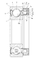
以下、図面に基づき、本発明の実施形態を説明する。この回転センサ付き転がり軸受は、図1に示すように、内輪1と外輪2の間にボール3が保持器4で保持された深溝玉軸受であり、内輪1が回転軌道輪、外輪2が固定軌道輪とされて、内輪1の片側に磁気エンコーダ6が装着され、これと対向する外輪2の片側に、磁気センサ7と回路基板8が組み込まれたセンサハウジング9が装着されている。なお、外輪2のセンサハウジング9と反対側には、軸受内部をシールするシール部材5が装着されている。
Hereinafter, embodiments of the present invention will be described with reference to the drawings. As shown in FIG. 1, this rolling bearing with a rotation sensor is a deep groove ball bearing in which a
前記磁気エンコーダ6は、環状の芯金6aと、芯金6aの外径面に固着され、円周方向で交互に異なる磁極に着磁された磁性体6bとからなり、芯金6aが内輪1の外径面に嵌合固定されている。
The
前記センサハウジング9は、ポリフェニレンサルファイド(PPS)にポリアミド(PA)とポリイミド(PI)を混合したポリマーアロイで形成され、外部の有害な磁界を遮蔽するためと、腐食を防止するために、磁性材であるフェライト系ステンレス鋼板SUS430をプレス成形した外環10と側環11とで覆われている。センサハウジング9は外環10の内径面に圧入され、外環10は外輪2の内径面に嵌合固定されて、その内端側に軸受内部をシールするシール部10aが形成されている。
The
前記センサハウジング9を形成するPPSにPAとPIを混合したポリマーアロイは、PPS単体のものに比べてガラス転移温度が高くなるので、高温状態から温度低下したときの温度変化に伴う圧入固定された外環10との緩みが生じ難く、温度クリープを抑制することができる。
A polymer alloy in which PA and PI are mixed with PPS forming the
図1および図2に示すように、前記磁気センサ7は、センサハウジング9の円周方向に近接させた2箇所に、磁気エンコーダ6と半径方向で対向するように配置されて、脚部7aで回路基板8に接続され、この回路基板8に接続された磁気センサ7の出力ケーブル12が、センサハウジング9と一体に形成された筒状の取り出し部9aを通して外部に取り出されている。センサハウジング9内の磁気センサ7、回路基板8および出力ケーブル12は、モールド樹脂13で固定されている。なお、円周方向に近接させて2つの磁気センサ7を配置したのは、両者の検出出力のずれから、回転方向を検出するためである。
As shown in FIG. 1 and FIG. 2, the
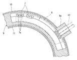
前記センサハウジング9の取り出し部9aは、図3(a)に示すように、側面に筒状の基端から先端まで等幅で連なる開放部14が設けられ、この開放部14から出力ケーブル12を取り出し部9aに通した後で、開放部14に蓋部材15が装着される。蓋部材15はセンサハウジング9と同じポリマーアロイで形成され、図3(b)に示すように、両側に設けられた張り出し部15aを開放部14の両側に設けられた溝16に先端側から嵌め込み、基端側へスライドさせて溝16の奥端面16aに押し当てることにより、開放部14を閉塞するように装着される。
As shown in FIG. 3 (a), the
こののち、前記取り出し部9aの先端側の出力ケーブル12との隙間に、シリコーン等のコーキング剤を充填して、取り出し部9aを含むセンサハウジング9内に、エポキシ樹脂やウレタン樹脂等の熱硬化性のモールド樹脂13が充填されるとともに、蓋部材15がセンサハウジング9に接着固定される。
Thereafter, a caulking agent such as silicone is filled in the gap between the
上述した実施形態では、転がり軸受を内輪が回転軌道輪とされた深溝玉軸受としたが、本発明に係る回転センサ付き転がり軸受は、ころ軸受等の他のタイプの転がり軸受にも適用することができる。また、外輪が回転軌道輪とされた転がり軸受にも適用でき、この場合は、回転センサの磁気エンコーダを外輪側に、磁気センサを組み込んだセンサハウジングを内輪側に装着すればよい。 In the embodiment described above, the rolling bearing is a deep groove ball bearing in which the inner ring is a rotating raceway ring. However, the rolling bearing with a rotation sensor according to the present invention is also applicable to other types of rolling bearings such as a roller bearing. Can do. Also, the present invention can be applied to a rolling bearing in which the outer ring is a rotating raceway. In this case, the magnetic encoder of the rotation sensor may be mounted on the outer ring side, and the sensor housing incorporating the magnetic sensor may be mounted on the inner ring side.
1 内輪
2 外輪
3 ボール
4 保持器
5 シール部材
6 磁気エンコーダ
6a 芯金
6b 磁性体
7 磁気センサ
7a 脚部
8 回路基板
9 センサハウジング
9a 取り出し部
10 外環
10a シール部
11 側環
12 出力ケーブル
13 モールド樹脂
14 開放部
15 蓋部材
15a 張り出し部
16 溝
16a 奥端面
DESCRIPTION OF
Claims (2)
前記筒状の取り出し部の開放部を筒状の基端から先端まで等幅で連なるものとし、前記蓋部材をこの等幅の開放部に、その先端側から基端側へスライドさせて装着するものとし、この装着後、前記取り出し部を含むセンサハウジング内の前記磁気センサ、前記回路基板及び前記出力ケーブルを熱硬化性のモールド樹脂で固定する前に、前記取り出し部の先端側の出力ケーブルとの隙間にコーキング剤を充填したことを特徴とする回転センサ付き転がり軸受。 An annular magnetic encoder magnetized with magnetic poles alternately arranged in the circumferential direction is mounted on the rotating raceway side of the inner and outer raceways, and a magnetic that detects a change in magnetic flux accompanying the rotation of the magnetic encoder is detected. A resin sensor housing incorporating a sensor is mounted on the stationary race ring side, and a cylindrical take-out portion through which the output cable of the magnetic sensor connected to the circuit board passes is integrally formed in the resin sensor housing. In the rolling bearing with a rotation sensor, an opening portion is provided on the side surface of the cylindrical take-out portion from the base end to the tip end, and the output cable is passed through the take-out portion from the open portion, and then the open portion is opened. A cover member is attached to the part so as to close the open part,
The open part of the cylindrical take-out part is connected to the cylindrical base end to the front end with a uniform width, and the lid member is slid from the front end side to the base end side and attached to the constant width open part. After the mounting, before fixing the magnetic sensor, the circuit board, and the output cable in the sensor housing including the extraction portion with a thermosetting mold resin, the output cable on the tip side of the extraction portion and A rolling bearing with a rotation sensor, characterized in that a caulking agent is filled in the gap.
Grooves are provided on both sides of the open part, and projecting parts are provided on both sides of the lid member. The rolling bearing with a rotation sensor according to claim 1, wherein the rolling bearing is mounted so as to close the open portion by being pressed against a back end surface of the groove.
Priority Applications (5)
| Application Number | Priority Date | Filing Date | Title |
|---|---|---|---|
| JP2006294529A JP5214869B2 (en) | 2006-10-30 | 2006-10-30 | Rolling bearing with rotation sensor |
| EP07830737.8A EP2078962B1 (en) | 2006-10-30 | 2007-10-29 | Rolling bearing with rotation sensor |
| CN2007800375763A CN101535817B (en) | 2006-10-30 | 2007-10-29 | Rolling bearing with rotation sensor |
| PCT/JP2007/071003 WO2008053823A1 (en) | 2006-10-30 | 2007-10-29 | Rolling bearing with rotation sensor |
| US12/447,507 US8188729B2 (en) | 2006-10-30 | 2007-10-29 | Rolling bearing with a rotation sensor |
Applications Claiming Priority (1)
| Application Number | Priority Date | Filing Date | Title |
|---|---|---|---|
| JP2006294529A JP5214869B2 (en) | 2006-10-30 | 2006-10-30 | Rolling bearing with rotation sensor |
Publications (2)
| Publication Number | Publication Date |
|---|---|
| JP2008111480A JP2008111480A (en) | 2008-05-15 |
| JP5214869B2 true JP5214869B2 (en) | 2013-06-19 |
Family
ID=39344164
Family Applications (1)
| Application Number | Title | Priority Date | Filing Date |
|---|---|---|---|
| JP2006294529A Active JP5214869B2 (en) | 2006-10-30 | 2006-10-30 | Rolling bearing with rotation sensor |
Country Status (5)
| Country | Link |
|---|---|
| US (1) | US8188729B2 (en) |
| EP (1) | EP2078962B1 (en) |
| JP (1) | JP5214869B2 (en) |
| CN (1) | CN101535817B (en) |
| WO (1) | WO2008053823A1 (en) |
Families Citing this family (15)
| Publication number | Priority date | Publication date | Assignee | Title |
|---|---|---|---|---|
| JP5349157B2 (en) * | 2009-06-19 | 2013-11-20 | Ntn株式会社 | Rotation detection device and bearing with rotation detection device |
| JP5451544B2 (en) * | 2009-10-22 | 2014-03-26 | Ntn株式会社 | Bearing with sensor |
| EP2652448B1 (en) * | 2010-12-17 | 2018-12-05 | Aktiebolaget SKF (publ) | Rotation detection set and bearing assembly comprising such a detection set |
| EP2852844B1 (en) * | 2012-05-22 | 2019-07-10 | Aktiebolaget SKF | Sensor-bearing unit and apparatus comprising such a unit |
| JP5857932B2 (en) * | 2012-10-03 | 2016-02-10 | アイシン精機株式会社 | Manufacturing method of sensor unit |
| JP2015094454A (en) | 2013-11-14 | 2015-05-18 | Ntn株式会社 | Rolling bearing with rotation sensor |
| CN103883628A (en) * | 2014-03-12 | 2014-06-25 | 摩士集团股份有限公司 | Bearing capable of detecting motion |
| CN105987657B (en) * | 2015-02-12 | 2018-12-07 | 珠海格力电器股份有限公司 | Current vortex sensor and turning gear for shaft |
| GB201506138D0 (en) * | 2015-04-10 | 2015-05-27 | Skf Ab | Capped bearing with vibration sensor |
| ITUA20162243A1 (en) * | 2016-04-01 | 2017-10-01 | Skf Ab | Sensorized bush-bearing unit for supporting a rail axle. |
| FR3086891B1 (en) * | 2018-10-03 | 2020-12-18 | Valeo Systemes Thermiques | ELECTRONIC COMPONENT FOR MOTOR VEHICLES |
| EP4172571A1 (en) * | 2020-06-29 | 2023-05-03 | Voith Patent GmbH | Housing for a rotating component |
| DE102020121188A1 (en) * | 2020-08-12 | 2022-02-17 | Schaeffler Technologies AG & Co. KG | Bearing with a sensor system and method for producing a bearing |
| CN113219199B (en) * | 2021-05-07 | 2023-05-26 | 武昌理工学院 | Method for detecting rotation of shaft lever in radar lower cavity |
| CN113188574B (en) * | 2021-05-25 | 2022-10-18 | 上海电气智能康复医疗科技有限公司 | Split type coding assembly, speed reducer module and installation method |
Family Cites Families (29)
| Publication number | Priority date | Publication date | Assignee | Title |
|---|---|---|---|---|
| IN149928B (en) * | 1977-07-22 | 1982-06-05 | Ransome Hoffmann Pollard | |
| DE2832449C2 (en) * | 1978-07-24 | 1985-04-18 | Ceag Licht- Und Stromversorgungstechnik Gmbh, 4770 Soest | Terminal block and method of making connections with its help |
| US4336517A (en) * | 1978-09-21 | 1982-06-22 | Jidosha Denki Kogyo Kabushiki Kaisha | Revolution detecting device |
| US4602891A (en) * | 1985-05-10 | 1986-07-29 | Mcbride Arlen P | Open wedge socket |
| IT207775Z2 (en) * | 1986-04-22 | 1988-02-15 | Weber Spa | PROVISION FOR THE EXTERNAL CONNECTION OF ELECTRIC CABLES FROM A CONTAINER BODY |
| DE3706168A1 (en) * | 1987-02-26 | 1988-09-08 | Bosch Gmbh Robert | SENSOR |
| US5122741A (en) * | 1989-12-06 | 1992-06-16 | Alps Electric Co., Ltd. | Holding members for sensor and wiring members of magnetic rotary encoder |
| GB2244605B (en) * | 1990-05-31 | 1994-05-18 | Britmac Electrical Limited | Cable trunking |
| JPH06327181A (en) * | 1993-05-17 | 1994-11-25 | Matsushita Electric Ind Co Ltd | Waterproofing device of connection part for resin-molded motor |
| IT1267384B1 (en) * | 1994-02-15 | 1997-02-05 | Trw Sipea Spa | METHOD FOR MAKING A SENSOR ASSEMBLY FOR AN ELECTROMAGNETIC DETECTOR DEVICE AND THE SENSOR ASSEMBLY ITSELF. |
| JP2825445B2 (en) * | 1994-08-31 | 1998-11-18 | 矢崎総業株式会社 | connector |
| JPH11513797A (en) * | 1995-10-17 | 1999-11-24 | サイエンティフィック ジェネリクス リミテッド | Position detection encoder |
| JPH09138240A (en) * | 1995-11-15 | 1997-05-27 | Fujitsu Ten Ltd | Detection apparatus for rotational speed |
| JPH09164948A (en) * | 1995-12-18 | 1997-06-24 | Hitachi Ltd | Window structure of rolling stock |
| JPH11185868A (en) * | 1997-12-18 | 1999-07-09 | Yazaki Corp | Pressure connection connector |
| JP2000343939A (en) * | 1999-06-07 | 2000-12-12 | Nippon Sheet Glass Co Ltd | Window construction for vehicle and fitting construction of window for vehicle |
| FR2807798B1 (en) * | 2000-04-12 | 2002-07-26 | Skf France | ANGULAR MOTION DETECTION DEVICE AND INSTRUMENTARY ROLLING BEARING |
| JP4432231B2 (en) * | 2000-07-31 | 2010-03-17 | 株式会社デンソー | Rotation detector |
| JP2002100438A (en) * | 2000-09-25 | 2002-04-05 | Hoshizaki Electric Co Ltd | Waterproof structure for wiring connector |
| JP4060037B2 (en) * | 2001-01-15 | 2008-03-12 | Ntn株式会社 | Bearing with rotation sensor |
| JP4916056B2 (en) * | 2001-06-11 | 2012-04-11 | 矢崎総業株式会社 | Manufacturing method of waterproof wire harness |
| EP2913679B1 (en) * | 2002-10-28 | 2018-12-05 | NSK Ltd. | Bearing apparatus with sensor and rolling bearing with sensor |
| JP4258221B2 (en) * | 2003-02-12 | 2009-04-30 | 株式会社ジェイテクト | Sensor assembly, sealing device and rolling bearing device |
| JP4385789B2 (en) * | 2004-02-20 | 2009-12-16 | 株式会社デンソー | Rotation detector |
| JP4085079B2 (en) * | 2004-07-20 | 2008-04-30 | 住電エレクトロニクス株式会社 | Rotation detection sensor |
| JP2006258542A (en) * | 2005-03-16 | 2006-09-28 | Ntn Corp | Bearing device having rotation sensor |
| WO2007077700A1 (en) * | 2006-01-06 | 2007-07-12 | Ntn Corporation | Rotation angle detector and bearing with rotation angle detector |
| FR2904412B1 (en) * | 2006-07-27 | 2008-10-17 | Snr Roulements Sa | METHOD FOR DETERMINING TWO QUADRATURE SIGNALS |
| WO2008075569A1 (en) * | 2006-12-21 | 2008-06-26 | Namiki Seimitsu Houseki Kabushikikaisha | Miniature rotary encoder |
-
2006
- 2006-10-30 JP JP2006294529A patent/JP5214869B2/en active Active
-
2007
- 2007-10-29 CN CN2007800375763A patent/CN101535817B/en active Active
- 2007-10-29 WO PCT/JP2007/071003 patent/WO2008053823A1/en active Application Filing
- 2007-10-29 US US12/447,507 patent/US8188729B2/en active Active
- 2007-10-29 EP EP07830737.8A patent/EP2078962B1/en active Active
Also Published As
| Publication number | Publication date |
|---|---|
| US20100052662A1 (en) | 2010-03-04 |
| EP2078962A4 (en) | 2017-07-26 |
| EP2078962A1 (en) | 2009-07-15 |
| JP2008111480A (en) | 2008-05-15 |
| CN101535817A (en) | 2009-09-16 |
| WO2008053823A1 (en) | 2008-05-08 |
| EP2078962B1 (en) | 2019-09-25 |
| CN101535817B (en) | 2011-12-07 |
| US8188729B2 (en) | 2012-05-29 |
Similar Documents
| Publication | Publication Date | Title |
|---|---|---|
| JP5214869B2 (en) | Rolling bearing with rotation sensor | |
| EP3001057B1 (en) | Sensor-equipped rolling bearing, motor, and actuator | |
| WO2009116445A1 (en) | Bearing equipped with rotation sensor | |
| WO2006115162A1 (en) | Bearing having rotary sensor | |
| JP4851381B2 (en) | Rolling bearing with rotation sensor | |
| JP2009036233A (en) | Bearing with sensor | |
| JP5321115B2 (en) | Rolling bearing with rotation sensor | |
| JP4829824B2 (en) | Rolling bearing with rotation sensor | |
| JP2009036235A (en) | Bearing | |
| JP5018114B2 (en) | Bearing with sensor | |
| JP2007211840A (en) | Bearing with sensor | |
| JP2023059707A (en) | Rolling bearing with rotary sensor | |
| JP2004361362A (en) | Rolling bearing with rotation sensor | |
| US20130285650A1 (en) | Rotation speed detecting apparatus | |
| JP4739804B2 (en) | Bearing with rotation sensor | |
| JP2008190688A (en) | Bearing with sensor | |
| JP2007192653A (en) | Rolling bearing with rotation sensor | |
| JP2007285337A (en) | Rolling bearing with rotary sensor | |
| JP2010190248A (en) | Roller bearing with rotation sensor | |
| JP2008185068A (en) | Seal device with sensor | |
| JP2007240443A (en) | Rolling bearing with rotation angle sensor and method of correcting detection output of magnetic sensor | |
| JP2008196632A (en) | Rolling bearing with rotation sensor | |
| JP2008116232A (en) | Magnetic encoder and rolling bearing | |
| JP2010002002A (en) | Rolling bearing device with sensor | |
| JP2005098509A (en) | Rolling bearing with sensor |
Legal Events
| Date | Code | Title | Description |
|---|---|---|---|
| A621 | Written request for application examination |
Free format text: JAPANESE INTERMEDIATE CODE: A621 Effective date: 20090916 |
|
| A131 | Notification of reasons for refusal |
Free format text: JAPANESE INTERMEDIATE CODE: A131 Effective date: 20120131 |
|
| A521 | Request for written amendment filed |
Free format text: JAPANESE INTERMEDIATE CODE: A523 Effective date: 20120330 |
|
| A02 | Decision of refusal |
Free format text: JAPANESE INTERMEDIATE CODE: A02 Effective date: 20120911 |
|
| A521 | Request for written amendment filed |
Free format text: JAPANESE INTERMEDIATE CODE: A523 Effective date: 20121207 |
|
| A911 | Transfer to examiner for re-examination before appeal (zenchi) |
Free format text: JAPANESE INTERMEDIATE CODE: A911 Effective date: 20121214 |
|
| TRDD | Decision of grant or rejection written | ||
| A01 | Written decision to grant a patent or to grant a registration (utility model) |
Free format text: JAPANESE INTERMEDIATE CODE: A01 Effective date: 20130212 |
|
| A61 | First payment of annual fees (during grant procedure) |
Free format text: JAPANESE INTERMEDIATE CODE: A61 Effective date: 20130228 |
|
| R150 | Certificate of patent or registration of utility model |
Ref document number: 5214869 Country of ref document: JP Free format text: JAPANESE INTERMEDIATE CODE: R150 Free format text: JAPANESE INTERMEDIATE CODE: R150 |
|
| FPAY | Renewal fee payment (event date is renewal date of database) |
Free format text: PAYMENT UNTIL: 20160308 Year of fee payment: 3 |
|
| R250 | Receipt of annual fees |
Free format text: JAPANESE INTERMEDIATE CODE: R250 |
|
| R250 | Receipt of annual fees |
Free format text: JAPANESE INTERMEDIATE CODE: R250 |
|
| R250 | Receipt of annual fees |
Free format text: JAPANESE INTERMEDIATE CODE: R250 |
|
| R250 | Receipt of annual fees |
Free format text: JAPANESE INTERMEDIATE CODE: R250 |
|
| R250 | Receipt of annual fees |
Free format text: JAPANESE INTERMEDIATE CODE: R250 |
|
| R250 | Receipt of annual fees |
Free format text: JAPANESE INTERMEDIATE CODE: R250 |
|
| R250 | Receipt of annual fees |
Free format text: JAPANESE INTERMEDIATE CODE: R250 |
|
| R250 | Receipt of annual fees |
Free format text: JAPANESE INTERMEDIATE CODE: R250 |
|
| R250 | Receipt of annual fees |
Free format text: JAPANESE INTERMEDIATE CODE: R250 |