JP5213701B2 - Rendering method, signal processing system, display device, and computer-readable medium - Google Patents
Rendering method, signal processing system, display device, and computer-readable medium Download PDFInfo
- Publication number
- JP5213701B2 JP5213701B2 JP2008510689A JP2008510689A JP5213701B2 JP 5213701 B2 JP5213701 B2 JP 5213701B2 JP 2008510689 A JP2008510689 A JP 2008510689A JP 2008510689 A JP2008510689 A JP 2008510689A JP 5213701 B2 JP5213701 B2 JP 5213701B2
- Authority
- JP
- Japan
- Prior art keywords
- signal
- image signal
- display
- rendering
- pixel
- Prior art date
- Legal status (The legal status is an assumption and is not a legal conclusion. Google has not performed a legal analysis and makes no representation as to the accuracy of the status listed.)
- Expired - Fee Related
Links
Images


Classifications
-
- H—ELECTRICITY
- H04—ELECTRIC COMMUNICATION TECHNIQUE
- H04N—PICTORIAL COMMUNICATION, e.g. TELEVISION
- H04N13/00—Stereoscopic video systems; Multi-view video systems; Details thereof
- H04N13/10—Processing, recording or transmission of stereoscopic or multi-view image signals
- H04N13/106—Processing image signals
- H04N13/15—Processing image signals for colour aspects of image signals
-
- H—ELECTRICITY
- H04—ELECTRIC COMMUNICATION TECHNIQUE
- H04N—PICTORIAL COMMUNICATION, e.g. TELEVISION
- H04N13/00—Stereoscopic video systems; Multi-view video systems; Details thereof
- H04N13/10—Processing, recording or transmission of stereoscopic or multi-view image signals
-
- H—ELECTRICITY
- H04—ELECTRIC COMMUNICATION TECHNIQUE
- H04N—PICTORIAL COMMUNICATION, e.g. TELEVISION
- H04N13/00—Stereoscopic video systems; Multi-view video systems; Details thereof
- H04N13/30—Image reproducers
- H04N13/302—Image reproducers for viewing without the aid of special glasses, i.e. using autostereoscopic displays
- H04N13/305—Image reproducers for viewing without the aid of special glasses, i.e. using autostereoscopic displays using lenticular lenses, e.g. arrangements of cylindrical lenses
-
- H—ELECTRICITY
- H04—ELECTRIC COMMUNICATION TECHNIQUE
- H04N—PICTORIAL COMMUNICATION, e.g. TELEVISION
- H04N2213/00—Details of stereoscopic systems
- H04N2213/003—Aspects relating to the "2D+depth" image format
Landscapes
- Engineering & Computer Science (AREA)
- Multimedia (AREA)
- Signal Processing (AREA)
- Testing, Inspecting, Measuring Of Stereoscopic Televisions And Televisions (AREA)
- Controls And Circuits For Display Device (AREA)
- Image Processing (AREA)
- Processing Or Creating Images (AREA)
- Facsimile Image Signal Circuits (AREA)
- Color Image Communication Systems (AREA)
Description
本発明は、概して画像信号処理の分野に関連する。特に、本発明は、3Dレンチキュラー又はバリアディスプレイの表示のための画像信号処理に関し、さらに特定すると、3Dレンチキュラー又はバリアディスプレイの表示のため画像信号をレンダリングするとき信号の知覚される画質を保持することに関する。 The present invention relates generally to the field of image signal processing. In particular, the present invention relates to image signal processing for 3D lenticular or barrier display display, and more particularly to preserve the perceived image quality of the signal when rendering the image signal for 3D lenticular or barrier display display. About.
3Dイメージは、両眼視差の働きであり、観察者に相対的な奥行き知覚を提供する。凝視された対象のイメージが異なる網膜の点に位置するので、結果としての網膜歪覚が刺激を与え、観察者の視覚システム(視覚系)により立体視の感覚が生じる。視覚システム内において、刺激に基づいて、組み合わせたり別個に実施される、精細な若しくは粗い立体視、又は奥行きのある動き、静的な動き若しくは横の動きの立体視のような種々の立体視の態様で特定する別個の神経学的サブシステムが、観察者に3D画像を作り出す。2D画像が観察者の視覚システムに3D画像として提示される種々の手段が現在ある。 The 3D image is a binocular parallax effect and provides relative depth perception to the viewer. As the stared image of the subject is located at a different retinal point, the resulting retinal distortion gives a stimulus, and the viewer's visual system (visual system) gives a sense of stereoscopic vision. Within a visual system, various stereopsis such as fine or coarse stereopsis, or deep motion, static motion or lateral motion stereopsis, combined or separately performed based on stimuli A separate neurological subsystem identified in the aspect creates a 3D image for the viewer. There are currently various means by which 2D images are presented as 3D images to the viewer's visual system.
国際特許公開公報WO/99/05559では、レンチキュラースクリーンがかぶせられ、インタレースされるべき複数の視点に対する画像データが提供されるとき、複数の視点の自動立体視ディスプレイとして表示装置を駆動するための表示装置のピクセルアドレッシング制御方法が供されている。少なくともレンチキュラースクリーンのレンズピッチと、各表示カラーピクセルに対しての表示装置に関する全体的なレンチキュラースクリーン位置とを規定するデータに基づいて、N個の視点の導出がなされる。それから、割り当てられた視点に対して対応するピクセルデータが、表示ピクセルデータとして選択される。WO/99/05559に記述された方法に基づいて制御された複数の視点の表示装置の画質が比較的良好だが、表示される画像を作るために必要とされる信号処理量は、膨大である。 In International Patent Publication No. WO / 99/05559, when a lenticular screen is covered and image data for a plurality of viewpoints to be interlaced is provided, the display device is driven as an autostereoscopic display of a plurality of viewpoints. A pixel addressing control method for a display device is provided. N viewpoints are derived based on data defining at least the lens pitch of the lenticular screen and the overall lenticular screen position for the display device for each display color pixel. Then, the pixel data corresponding to the assigned viewpoint is selected as display pixel data. Although the image quality of the display device of a plurality of viewpoints controlled based on the method described in WO / 99/05559 is relatively good, the amount of signal processing required to produce a displayed image is enormous. .
2Dラスタディスプレイを使用する現行の3Dグラフィックシステムは、遠近アルゴリズムを使って2Dグラフィックスのラスタディスプレイ上に対象物をレンダリングすることにより、リアルな3D効果を通常達成する。 Current 3D graphics systems that use 2D raster displays typically achieve realistic 3D effects by rendering objects on 2D graphics raster displays using perspective algorithms.
図1は、視点が個別のサブピクセルでマッピングされるようなディスプレイが構成される、3Dディスプレイの2.5Dビデオ信号をレンダリングするための既知の信号処理システムを示す。レンダリングシステム100はYUVD信号を受信し、当該YUVD信号は変換器102により既知のやり方でRGBD信号へ変換される。それからRGBD信号は、スケーラ104によりスケーラされ、個別のR、G、BのD成分となる。それから視点レンダリング器106は、RD、GD及びBD信号をレンダリングして新しいRGB信号を作る。視点レンダリング器106は、9回インスタンス化される。各インスタンス化は、一つの色成分で行う。これらR信号、G信号及びB信号は、統合ユニット108で一緒に統合され、表示スクリーン110に表示できる最終のRGB信号を作る。
FIG. 1 shows a known signal processing system for rendering a 2.5D video signal of a 3D display in which the display is configured such that the viewpoint is mapped with individual subpixels. The
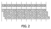
図2は、図1に示された信号処理システムによる9視点表示に対するそれぞれのサブピクセルの視点番号を示す。これは、2つの主な働き、奥行き変換及び適当なサブピクセルグリッドを生成するためのリサンプリングを実施する。視点レンダリング器の計算の複雑さは、高表示解像度のサブピクセル位置で動作するように現行技術の視点において著しい。更に、各色成分に対する計算負荷は等しい。したがって、3Dディスプレイに2.5Dビデオ信号をレンダリングするために実施しなければならない膨大な計算量がある。この計算負荷は、実時間で実施されるので、膨大な量の処理能力及び電力を要求する。 FIG. 2 shows viewpoint numbers of respective sub-pixels for nine viewpoint display by the signal processing system shown in FIG. This performs two main functions, depth conversion and resampling to generate a suitable sub-pixel grid. The computational complexity of the viewpoint renderer is significant in current technology viewpoints to operate at high display resolution sub-pixel positions. Furthermore, the calculation load for each color component is equal. Thus, there is a tremendous amount of computation that must be performed to render a 2.5D video signal on a 3D display. Since this computational load is implemented in real time, it requires a huge amount of processing power and power.
よって、改善された信号処理システムが有益であり、特に、受け入れられる画質を持った信号を作るために空間的誤差と視点誤差とのバランスをとる一方で、3Dディスプレイに画像データをレンダリングするために必要とされる計算量を大幅に減らしたレンダリングシステムが有利である。 Thus, an improved signal processing system is beneficial, particularly for rendering image data on a 3D display while balancing spatial and viewpoint errors to produce a signal with acceptable image quality. A rendering system that greatly reduces the amount of computation required is advantageous.
よって、本発明は、上述の1つ又は複数の従来技術の不具合や不利益を軽減、緩和又は排除するために探求し、少なくともこれらの問題解決するか又は少なくとも部分的には解決するために、添付の請求項による画像データを3Dディスプレイに効率的にレンダリングすることを提供する方法、装置及びコンピュータ可読媒体を提供する。 Accordingly, the present invention seeks to mitigate, mitigate or eliminate one or more of the prior art deficiencies and disadvantages described above, and at least to solve or at least partially solve these problems. Methods, apparatus and computer readable media are provided for providing efficient rendering of image data on a 3D display according to the appended claims.
本発明は、画像データを3Dレンチキュラー又はバリアディスプレイにレンダリングするとき、知覚される画質を保持しながら大きくコスト削減することを目的とする。このことは、YUVドメインでの処理及びU/V解像度の低減により主に実施される。視点誤差及び空間誤差は、YUV/RGBマトリクス内のサブピクセル値の新規な選択によりバランスがとれている。知覚される画質は、わずかに低減されているだけである。その上、YUVドメインでの処理は、奥行き依存の明るさ/コントラストの適応処理が処理チェーンの中でシームレスに合わせることが可能である。これは、知覚される奥行き印象を改善する。この情報は、計算負荷を少なくとも50%低減する。 An object of the present invention is to greatly reduce costs while maintaining perceived image quality when rendering image data on a 3D lenticular or barrier display. This is mainly done by processing in the YUV domain and reducing U / V resolution. Viewpoint error and spatial error are balanced by a novel selection of subpixel values in the YUV / RGB matrix. The perceived image quality is only slightly reduced. In addition, processing in the YUV domain can be seamlessly combined with depth-dependent brightness / contrast adaptation processing in the processing chain. This improves the perceived depth impression. This information reduces the computational load by at least 50%.
本発明の態様によると、画像データを3Dディスプレイにレンダリングするための方法、装置及びコンピュータ可読媒体が開示されている。 In accordance with aspects of the present invention, a method, apparatus and computer readable medium for rendering image data on a 3D display is disclosed.
本発明の一つの態様によると、3Dディスプレイに画像データをレンダリングするための方法であって、第1の画像信号を受信するステップと、低減された空間解像度において第1の画像信号の少なくとも1つの色成分をレンダリングして第2の画像信号を作成するステップと、前記3Dディスプレイ用にフル解像度信号を再構成するときに空間的誤差及び視点誤差がバランスされるように第2の画像信号を空間的フィルタリングするステップとを有する方法が提供される。 According to one aspect of the invention, a method for rendering image data on a 3D display, receiving a first image signal, and at least one of the first image signal at a reduced spatial resolution. Rendering a color component to create a second image signal; and spatializing the second image signal so that spatial and viewpoint errors are balanced when reconstructing a full resolution signal for the 3D display. Filtering is provided.
本発明の他の一つの態様によると、3Dディスプレイに画像データをレンダリングする信号処理システムであって、第1の画像信号を受信する手段と、低減された空間解像度において第1の画像信号の少なくとも1つの色成分をレンダリングして第2の画像信号を作成する手段と、前記3Dディスプレイ用にフル解像度信号を再構成するときに空間的誤差及び視点誤差がバランスされるように第2の画像信号を空間的フィルタリングする手段とを有する、信号処理システムが提供される。 According to another aspect of the invention, a signal processing system for rendering image data on a 3D display, comprising: means for receiving a first image signal; and at least a first image signal at a reduced spatial resolution. Means for rendering a single color component to create a second image signal, and a second image signal so that spatial and viewpoint errors are balanced when reconstructing a full resolution signal for the 3D display. And a means for spatially filtering the signal processing system.
本発明の更に他の一つの態様によると、3Dディスプレイに画像データをレンダリングするコンピュータによる処理のためのコンピュータプログラムを実装したコンピュータ可読媒体であって、前記コンピュータプログラムは、低減された空間解像度において第1の画像信号の少なくとも1つの色成分をレンダリングして第2の画像信号を作成するためのコードセグメントと、前記3Dディスプレイ用にフル解像度信号を再構成するときに空間的誤差及び視点誤差がバランスされるように第2の画像信号を空間的フィルタリングするためのコードセグメントとを有する、コンピュータ可読媒体が提供される。 According to yet another aspect of the present invention, a computer readable medium implementing a computer program for processing by a computer that renders image data on a 3D display, the computer program having a reduced spatial resolution. A code segment for rendering a second image signal by rendering at least one color component of one image signal and a balance between spatial and viewpoint errors when reconstructing a full resolution signal for the 3D display And a code segment for spatially filtering the second image signal as provided.
本発明は、3Dディスプレイに表示される画像の知覚される画質を保持しながら、レンダリングシステムの計算負荷を低減して、従来技術を超える利点を持つ。 The present invention has the advantages over the prior art by reducing the computational load of the rendering system while preserving the perceived image quality of the image displayed on the 3D display.
本発明のこれら及び他の態様、特徴及び利点が、図を参照して本発明の実施例の下記の説明で明らかになり、説明されるだろう。 These and other aspects, features and advantages of the present invention will become apparent and will be elucidated in the following description of embodiments of the invention with reference to the drawings.
以下の説明は、ビデオ表示システム、特に3Dビデオ表示システムに適用可能な本発明の実施例に焦点を当てたものである。しかしながら、本発明はこの適用例に制限されるものではなく、他の多くのビデオ表示システムに適用されてもよいことは、理解されるだろう。更に、本発明は、2.5D信号(奥行きを補強した通常のビデオ)、ステレオ信号(左目及び右目の通常のビデオ信号)又はマルチ視点(例えば9視点ディスプレイのための9画像)のレンダリングにさえも適用する。加えて、実時間処理が要求されるので計算負荷の削減がビデオにとって非常に重要であるけれども、本発明は、例えばビデオ信号、静止画等の如何なるタイプの画像データにも適用する。 The following description focuses on embodiments of the present invention applicable to video display systems, particularly 3D video display systems. However, it will be appreciated that the invention is not limited to this application and may be applied to many other video display systems. Furthermore, the present invention can even render 2.5D signals (normal video with depth enhancement), stereo signals (normal video signals for left and right eyes) or even multi-viewpoints (eg 9 images for 9-view displays). Also apply. In addition, although the reduction of computational load is very important for video because real-time processing is required, the present invention applies to any type of image data such as video signals, still images, and the like.
以下の例では、傾斜配置のレンチキュラーを持つ直視型3D−LCDレンチキュラーアレイ表示装置100が、本発明を説明するために図3を参照して最初に説明されるだろう。
In the following example, a direct view 3D-LCD lenticular
これらの図は単に図式的なものであり、縮尺に合わせて示されていないことは、理解されるだろう。図を明瞭にするために、幾つかの大きさは誇張され、一方で他の大きさは縮小されている。また、同じ部品及び大きさを示すためにこれらの図を通じて、同じ参照符号及び文字が必要に応じて使用されている。 It will be understood that these figures are merely schematic and are not shown to scale. For clarity of illustration, some sizes are exaggerated while others are reduced. Also, the same reference numerals and letters are used as necessary throughout these figures to indicate the same parts and sizes.
図3を参照すると、表示装置10は、空間光変調器として用いられ、互いに直交する行と列とに並べられた個別にアドレス指定可能で同じような大きさの光生成素子12の板状アレイを有する従来のLCマトリクス表示パネル11を含む。少しの光生成素子だけが示されているが、実際は、約800列(又はフルカラー表示を提供するために用いられるRGBトリプレットを持つと、色では2400列)及び600行の表示素子である。斯様なパネルはよく知られていて、ここでは詳述されないだろう。
Referring to FIG. 3, the
光生成素子12は、ほぼ長方形の形状であり、2つの隣り合う列にある光生成素子が列方向(垂直方向)に延在するギャップにより分離され、2つの隣り合う行にある表示素子が行方向(水平方向)に延在するギャップにより分離されて、互いから定間隔で離れている。パネル11は、アクティブマトリクス型であり、各光生成素子はスイッチング素子と関連し、当該スイッチング素子は当該光生成素子に隣接して位置する、例えばTFT、薄膜ダイオード又はTDFを有する。
The
表示パネル11は、光源14により照射され、この例では光源14は表示素子アレイの領域に渡って延在する板状バックライトを有する。光源14からの光は、駆動電圧の適切な印加により個別の光生成素子が駆動されながら、前記表示パネルを通り、表示出力を生成するために従来のやり方でこの光を変調する。このようにして作られた表示を構成する光生成素子のアレイは、光生成素子の構造と一致し、各光生成素子はそれぞれの表示ピクセルを提供する。計算手段18は、入力信号に基づいてそれぞれの光生成素子のための輝度値を計算する。
The
パネル11の向うで、光源14に対向する側とは反対側に、細長い、平行なレンチキュラー又はレンズ素子のアレイを有するレンチキュラーシート15があり、これは、観察者の目に別々のイメージを供給するための光学的方向付け手段として動作し、シート15のパネル11とは離れた側に面する観察者へ立体視ディスプレイを作る。従来の型式のシート15のレンチキュラーは、例えば凸状の柱状レンズ又は段階的な反射率を持つ柱状レンズとして形成される光学的に(セミ)柱状の収束レンチキュラーを有する。マトリクス表示パネルと協同した斯様なレンチキュラーシートを用いる自動立体視表示装置は、よく知られているが、(表示素子列に対応する)表示ピクセル列に平行に延在するレンチキュラールを持つこのような装置の従来の配置とは違って、図3の装置のレンチキュラーは、光生成素子の列に関して傾斜し、すなわち、これらの主長軸が、光生成素子の構造の列方向と角度を持つ。この配置は、ヨーロッパ特許公開公報EP−A−0791847に述べられているように、解像度損失の低減及び光生成素子間のブラック領域の強化されたマスキングに関して非常に多くの利点をもたらすことがわかっている。図3に示されたディスプレイの動作説明は、本出願人の特許出願である整理番号PHNL050033EPPに説明されていて、この明細書に組み込まれる。
On the opposite side of the
簡略的に言うと、レンダリング処理は、幾つかの操作を有する。第1に、画像が、各視点(例えばビデオ+奥行き、又はステレオ)に対して計算される。次に、画像が視覚的解像度に適切にスケーラ(サイズ調整)される。それから画像は、視点のサブピクセル位置に適切にシフトする。これらの操作の幾つか又は全てが結合されてもよいことは、当業者には理解されるだろう。例えば、図2を参照すると、垂直方向のスケーラは別個になされ、視点レンダリング器はこれら3つの操作の水平方向の処理全てを実施する。 In short, the rendering process has several operations. First, an image is calculated for each viewpoint (eg video + depth or stereo). The image is then scaled appropriately for visual resolution. The image is then shifted appropriately to the subpixel position of the viewpoint. One skilled in the art will appreciate that some or all of these operations may be combined. For example, referring to FIG. 2, the vertical scaler is done separately and the viewpoint renderer performs all the horizontal processing of these three operations.
人間の視覚システム(HVS)においては、シャープネス(鮮鋭度)の印象は、輝度成分によって主に決定され、色成分によってはほとんど決定されない。このことは、奥行き認知に対しても当てはまることが示唆される。更に、多くの信号エネルギが輝度成分にあることを考慮されたい。更に、色空間変換がレンダリングに比較して相対的に廉価の操作であることを考慮されたい。 In the human visual system (HVS), the impression of sharpness (sharpness) is mainly determined by the luminance component and hardly determined by the color component. This suggests that this is also true for depth perception. Furthermore, consider that much signal energy is in the luminance component. Furthermore, consider that color space conversion is a relatively inexpensive operation compared to rendering.
シャープネスの印象が輝度成分により主に決定され、輝度は主要な部分がG信号であるので、垂直解像度の低減の主に有望な候補はB信号であり、度合いが少し減ってR信号である。本発明の第1実施例によると、B及びR成分は、フレームの各ラインに対しては計算されない。例えば、B及びR成分は、フレームの各偶数ラインでのみ計算され、偶数ライン間の垂直平均が奇数ライン上のB/R信号を計算するのに用いられる。結果として、B及び/又はR成分は、50%低減された垂直解像度を持つ。 Since the impression of sharpness is mainly determined by the luminance component, and the main portion of the luminance is the G signal, the main promising candidate for the reduction of the vertical resolution is the B signal, and the degree is slightly reduced to the R signal. According to the first embodiment of the present invention, the B and R components are not calculated for each line of the frame. For example, the B and R components are calculated only on each even line of the frame, and the vertical average between even lines is used to calculate the B / R signal on the odd lines. As a result, the B and / or R component has a 50% reduced vertical resolution.
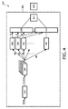
図4は、本発明の第1実施例によるビデオ信号処理システムを示す。このビデオ信号処理システムは、例えばテレビ受像機、コンピュータモニタ、携帯装置等の表示装置200の一部であってもよいことは、当業者には理解されるだろう。レンダリングシステム201は、YUVD信号を受信し、変換器202により既知の態様でRGBD信号に変換される。それから、このRGBD信号は、個別のR、G、BのD成分へスケーラ204によってスケーラされる。この実施例では、フレーム内の各偶数ラインに対するRD、GD及びBD成分が、各偶数ラインに対する新しいR、G、B信号を作るために、少なくとも一つの視点レンダリング器206へ送られる。その後、各偶数ラインに対するR、G、B信号は、統合ユニット210において一緒に統合される。加えて、フレーム内の各奇数ラインに対するGD成分は、フレーム内の各奇数ラインに対する新しいG信号を作るために(206と同様に振舞う)視点レンダリング器208へ送られる。以下に詳細に述べられるように、視点レンダリング器206、208は、レンダリング処理の間に作られる空間的誤差及び視点誤差により生じた視認可能な偽信号を最小にする態様でそれぞれの出力信号を空間的にフィルタリングする。上述したように、奇数ラインの各そばの偶数ラインに対するR及びB信号の平均値は、その後、フレームの奇数ラインのRGB信号を作るために、計算されたG信号と統合ユニット212において統合される。奇数ライン及び偶数ラインに対するRGB信号は、その後、ディスプレイ216へ送られる最終的なRGB信号を作るためにユニット214において結合される。
FIG. 4 shows a video signal processing system according to a first embodiment of the present invention. Those skilled in the art will appreciate that this video signal processing system may be part of a
上述したように、レンダリング処理は空間的誤差及び視点誤差を作ってしまう。当該空間的誤差は、空間距離と呼ばれる。空間距離が近いほど、サンプル値は相関がよりあるので、近接した空間的位置は最小の誤差を提供する。視点誤差は、視点数と呼ばれる。視点数の大きな差は、大きな視差と関係し、よって、最小の視点の差は最小の誤差を提供する。0の視点誤差だけが、同じ視点からのサンプル値の使用を許容し、非常に大きな空間距離となって、重大な全体の誤差を導く。最小の空間誤差は、幾つかのケースの場合、非常に大きな視差となる非常に大きな視点の誤差となり、重大な全体の誤差を導く。本発明のこの実施例では、2つの誤差は、空間的フィルタリングを用いてバランスされ、良好な画質となる。 As described above, the rendering process creates a spatial error and a viewpoint error. This spatial error is called spatial distance. The closer the spatial distance, the more correlated the sample values, so the close spatial location provides the smallest error. The viewpoint error is called the number of viewpoints. A large difference in the number of viewpoints is related to a large parallax, and thus a minimum viewpoint difference provides a minimum error. Only a zero viewpoint error allows the use of sample values from the same viewpoint, resulting in a very large spatial distance, leading to a significant overall error. The smallest spatial error, in some cases, results in a very large viewpoint error that results in a very large parallax, leading to a significant overall error. In this embodiment of the invention, the two errors are balanced using spatial filtering, resulting in good image quality.
実験は、この解決の仕方が良い結果を生み出すことを示した。誤差は垂直解像度だけでなく奥行きにもあることに留意されたい。1ラインの垂直オフセットは、1視点誤差となる。異なるフィルタトポロジを選択することによって、空間的精度と奥行きの精度とが交換されてもよい。よって、空間的フィルタ設計は、ディスプレイの奥行き特性及び空間的特性の両方を考慮する。本発明の一つの実施例によると、空間的誤差の訂正を視点誤差の訂正とバランスをとるように空間的フィルタが選択されるので、誤差は多くの視認できる偽信号を生じない。この解決の仕方は、ほとんど視認できる偽信号を導かないことが証明された。平均的演算の計算負荷が視点レンダリングと比較して無視できるので、このことは1/3の計算を減らす。 Experiments have shown that this solution produces good results. Note that the error is not only in vertical resolution but also in depth. One line of vertical offset results in one viewpoint error. By selecting different filter topologies, spatial accuracy and depth accuracy may be exchanged. Thus, the spatial filter design considers both the depth and spatial characteristics of the display. According to one embodiment of the present invention, the spatial filter is selected to balance the correction of the spatial error with the correction of the viewpoint error, so that the error does not produce many visible spurious signals. This solution proved to lead to no visible false signal. This reduces the computation by 1/3, since the computational load of the average operation is negligible compared to viewpoint rendering.
本発明は、奇数ラインに対するR、G、B値を計算し、偶数ラインのR及びB値を見積もるために奇数ラインのR及びB値を用いてもよいことは、当業者には理解されるだろう。更に、奇数ラインに対するR及びB値の従来の計算は1奇数ラインおきの各奇数ライン、各第3番目のライン、各第4番目のライン等に対してスキップできることも理解されるだろう。 Those skilled in the art will appreciate that the present invention may calculate R, G, B values for odd lines and use the R and B values for odd lines to estimate the R and B values for even lines. right. It will further be appreciated that conventional calculations of R and B values for odd lines can be skipped for every odd line, every third line, every fourth line, etc. every other odd line.
本発明の他の実施例によると、レンダリングはYUVドメインで実施される。図5は、本発明のこの実施例によるビデオ信号処理システムを示す。このビデオ信号処理システムは、例えばテレビ、コンピュータモニタ、携帯装置等のような表示装置300の一部であってもよいことは、当業者には理解されるだろう。レンダリングシステム301はYUVD信号を受け取って、スケーラ302へ送る。前記YUVD信号は、スケーラ302によりスケーラされて個別のY、U、VのD成分になる。この実施例では、YD、UD、VD成分が新しいY、U、V信号を作るために視点レンダリング器304へ送られる。それから、Y、U、V信号は統合ユニットで一緒に統合される。それから、統合されたYUV信号は、変換器308によりRGB信号に変換される。YUV信号からRGB信号への変換は、上述したように特別に選択された空間的フィルタを用いることにより、ディスプレイの奥行き特性及び空間的特性の両方を考慮する。それから、RGB信号はディスプレイ310へ送られる。
According to another embodiment of the invention, rendering is performed in the YUV domain. FIG. 5 shows a video signal processing system according to this embodiment of the invention. Those skilled in the art will appreciate that the video signal processing system may be part of a
一見すると、これは、誤差を導入する一方でコスト削減を提供しない。先ず、誤差はできるだけたくさん減らされるべきである。後で、U/V信号の解像度の低減がどのくらい重大なコスト削減を導くかが示されるだろう。視点レンダリング器は、スクリーンのR、G及びBサブピクセル位置上で操作するように設計される。これらRGBの位置上にYUVを適切にマッピングするために、色空間変換マトリクスを考慮する。例として、ITU−R BT.601−5色マトリクスが下記のように付与される。
Y'=0.299*R'+0.587*G'+0.114*B'
U'=-0.169*R'-0.331*G'+0.500*B'
V'=0.500*R'-0.419*G'-0.081*B'
R'=Y'+1.402*V'
G'=Y'-0.344*U'-0.714*V'
B'=Y'+1.772*U'
At first glance, this introduces errors while providing no cost savings. First, the error should be reduced as much as possible. Later it will be shown how a significant reduction in U / V signal resolution leads to cost savings. The viewpoint renderer is designed to operate on the R, G and B subpixel positions of the screen. In order to properly map YUV on these RGB positions, a color space conversion matrix is considered. As an example, ITU-R BT. A 601-5 color matrix is given as follows.
Y '= 0.299 * R' + 0.587 * G '+ 0.114 * B'
U '=-0.169 * R'-0.331 * G' + 0.500 * B '
V '= 0.500 * R'-0.419 * G'-0.081 * B'
R '= Y' + 1.402 * V '
G '= Y'-0.344 * U'-0.714 * V'
B '= Y' + 1.772 * U '
最も主要な色成分を用いることが適当である。したがって、YはGにマッピングされ(すなわち、G信号であるかのように処理される)、UはBにマッピングされ、VはRにマッピングされる。YUVをRGBサブピクセル位置にこのようにマッピングすることは、図6に示されている。 It is appropriate to use the most principal color components. Thus, Y is mapped to G (ie, processed as if it were a G signal), U is mapped to B, and V is mapped to R. This mapping of YUV to RGB subpixel locations is shown in FIG.
YUVからRGBへの変換は、適切な予防措置が採られないならば重大な奥行き誤差を生じる。最も主要なドメイン寄与分は、正しい位置から採られるべきである。このことは、R、G及びBを計算するために用いられる以下のピクセルとなる。
R←(Y[x+1], V[x])
G←(Y[x], V[x-1], U[x+1])
B←(Y[x-1], U[x])
ここでxは現在のピクセル位置を示す。
YUV to RGB conversion can cause significant depth errors if proper precautions are not taken. The most significant domain contribution should be taken from the correct location. This results in the following pixels used to calculate R, G and B:
R ← (Y [x + 1], V [x])
G ← (Y [x], V [x-1], U [x + 1])
B ← (Y [x-1], U [x])
Here, x indicates the current pixel position.
この設定は、最大視点誤差が1となる。隣接するピクセル([x-1]又は[x+1])から値を採ることが最も近い空間的位置ではないことに留意されたい。最適な空間的位置だけが考慮されるのであれば、全ての値は位置[x]から採られたであろう。 With this setting, the maximum viewpoint error is 1. Note that taking a value from an adjacent pixel ([x-1] or [x + 1]) is not the closest spatial location. If only the optimal spatial location was considered, all values would have been taken from location [x].
実験は、この変換が知覚された画質の僅かの歪だけとなることを示した。 Experiments have shown that this transformation results in only a slight distortion of perceived image quality.
更なる精細さとして、幾つかのフィルタリングが、線形又は統計的順序フィルタの何れかを用いて適用されてもよい。例えば、
Rに対して、Y[y, x+1]及びY[y, x-2]を持つ線形フィルタ
Rに対して、Y[y, x+1]、Y[y-1, x+1]及び Y[y, x-2]を持つメディアンフィルタ
Bに対して、Y[y, x-1]及びY[y, x+2]を持つ線形フィルタ
Bに対して、Y[y, x-1]、Y[y+1, x-1]及び Y[y, x+2]を持つメディアンフィルタ
があり、ここでyは現在のライン位置を示す。
As a further refinement, some filtering may be applied using either linear or statistical order filters. For example,
For linear filter R with Y [y, x + 1] and Y [y, x-2] for R, Y [y, x + 1], Y [y-1, x + 1] And for median filter B with Y [y, x-2], for linear filter B with Y [y, x-1] and Y [y, x + 2], Y [y, x- There is a median filter with 1], Y [y + 1, x-1] and Y [y, x + 2], where y indicates the current line position.
ここで、U/V信号を処理するレンダリング器の例を得た。これは、
―低減された水平解像度において垂直スケーラを実行し(通常はTV信号は4::2:2でフォーマット化されていて、垂直スケーラにおいてU/Vデータ量を50%だけ低減している)、
―垂直スケーラの複雑さ、例えばフィルタのタブ数や低減した正確さを低減し、
―レンダリング器の一部である水平スケーラ/リサンプラの複雑さ、例えばフィルタのタブ数や低減した正確さを低減することにより、
これらチャネル上の知覚感度、帯域及び低減した信号エネルギの利点を採用することを許容する。
Here, an example of a renderer that processes U / V signals was obtained. this is,
-Perform a vertical scaler at reduced horizontal resolution (usually the TV signal is formatted 4 :: 2: 2, reducing the amount of U / V data by 50% in the vertical scaler),
-Reduce the complexity of vertical scalers, such as the number of filter tabs and reduced accuracy,
-By reducing the complexity of the horizontal scaler / resampler that is part of the renderer, such as the number of filter tabs and reduced accuracy,
Allowing the advantages of perceptual sensitivity, bandwidth and reduced signal energy on these channels to be adopted.
大まかに、U/V処理の複雑さは、Y処理と比較して少なくとも50%ほど低減される。ここでは、YUV/RGBマトリクスがより高いデータレートで走っているという事実を無視している。このとき、これは1/3の低減となる。 Broadly, the complexity of the U / V process is reduced by at least 50% compared to the Y process. Here, the fact that the YUV / RGB matrix is running at a higher data rate is ignored. At this time, this is a reduction of 1/3.
本発明の他の実施例によると、上述した低減された解像度のU/V信号が利用される。入力信号は普通4:2:2フォーマットであり、レンダリング中には水平方向では半分のピクセルだけが処理されることに留意されたい。この説明を簡単にすると、低減されたU/V解像度上でいかなる変形もなしに奥行きのレンダリングを実行し、簡易に出力値の半分だけを計算することを提案している。このとき、YUVからRGBへの変換は、U/V値が失われる各奇数ピクセル位置ごとに適応される必要がある。以下のデータ使用が、これら奇数位置に対して提案される。
R←(Y[y, x+1], V[y-2, x+1])
G←(Y[y, x], V[y, x-1], U[y, x+1])
B←(Y[y, x-1], U[y-2, x+1])
According to another embodiment of the present invention, the reduced resolution U / V signal described above is utilized. Note that the input signal is usually in 4: 2: 2 format and only half the pixels are processed in the horizontal direction during rendering. To simplify this explanation, it is proposed to perform depth rendering on the reduced U / V resolution without any deformation and simply calculate only half of the output value. At this time, the conversion from YUV to RGB needs to be applied to each odd pixel position where the U / V value is lost. The following data usage is proposed for these odd positions.
R ← (Y [y, x + 1], V [y-2, x + 1])
G ← (Y [y, x], V [y, x-1], U [y, x + 1])
B ← (Y [y, x-1], U [y-2, x + 1])
しかしながら、U/V値が隣接するピクセル位置から得ることはできないので、偶数位置での計算も適応される必要がある。この解決は、下記の通りである。
R←(Y[x+1], V[x])
G←(Y[x], V[x+2], U[x-2])
B←(Y[x-1], U[x])
However, since U / V values cannot be obtained from adjacent pixel positions, calculations at even positions also need to be adapted. This solution is as follows.
R ← (Y [x + 1], V [x])
G ← (Y [x], V [x + 2], U [x-2])
B ← (Y [x-1], U [x])
これは、最大視点誤差が1となる。2ラインの垂直距離を持つデータが用いられる(前のラインからではない)ことにも留意されたい。これは、垂直解像度を2倍低減する第1実施例と本実施例との単純な組み合わせとなることを許容する。2ラインのどちらかといえば大きな空間誤差がU及びV信号にのみあることにも留意されたい。 In this case, the maximum viewpoint error is 1. Note also that data with a vertical distance of 2 lines is used (not from the previous line). This allows a simple combination of the first embodiment that reduces the vertical resolution by a factor of 2 and this embodiment. Note also that there is only a large spatial error in the U and V signals, if any of the two lines.
更なる改良として、線形又は統計順序フィルタの何れかを用いて、幾つかのフィルタリングが適用される。例えば、
Rに対して、V[y-2, x+1]及びV[y+2, x-1]を持つ線形フィルタ
Bに対して、U[y-2, x+1]及びU[y+2, x-1]を持つ線形フィルタ
As a further improvement, some filtering is applied using either linear or statistical order filters. For example,
For R, U [y-2, x + 1] and U [y +] for linear filter B with V [y-2, x + 1] and V [y + 2, x-1] 2, x-1] linear filter
これらのピクセル位置は、必要とされるピクセル位置の周りに対しての空間的対称を示す。 These pixel locations show spatial symmetry about the required pixel location.
コスト削減はすぐに明らかである。垂直のスケーラ及び視点レンダリング器は、50%のU/V計算しか必要としない。よって、これは1/3だけ計算を低減する。 Cost savings are readily apparent. The vertical scaler and viewpoint renderer only require 50% U / V calculation. This therefore reduces the computation by 1/3.
本発明の追加のオプションは、奥行きに依存した信号処理を適用することである。奥行きの印象が、明度/コントラスト特性に関係し、すぐ近くのものよりも離れているもののシーンの方がより「ぼやけている」ことは、知覚リサーチから知られている。この知識は、輝度及び奥行き情報がレンダリングの段階で両方とも利用可能であり、奥行きに依存する輝度/コントラスト適応が例えば(奥行きが制御される)可変ゲイン又はルックアップテーブルにより容易に得られるので、レンダリングの段階で本発明に容易に適用できる。これは、改善された奥行き印象となる。奥行きに依存する信号処理の他の例は、シャープネスに関する。しばしば背景内の対象物は焦点がぼけている。この観察は信号処理に適用される。背景をぼかすことは、奥行き印象を改善する。したがって、奥行きに依存したシャープネス低減は、奥行き印象を強調する。シャープネス印象は主にビデオ信号の輝度成分により決定されるので、YUVドメインでこの奥行き依存シャープネスフィルタを適用することは有利である。更に、この奥行き依存フィルタリングは比較的安い余分なコストでYD信号を処理するレンダリングユニットに途切れなく一体化できるので、本発明は、特に有益なシステムを提供する。レンダリングの主な機能は、観察者に立体視の奥行きの役割を提供することである。依存型信号処理により、追加の奥行きの役割が供給される。 An additional option of the present invention is to apply depth dependent signal processing. It is known from perceptual research that the impression of depth is related to lightness / contrast characteristics, and that the scene is more “blurred” in the distance than in the immediate vicinity. This knowledge is that both luminance and depth information is available at the rendering stage, and depth-dependent luminance / contrast adaptation is easily obtained, for example, with a variable gain (depth controlled) or look-up table. It can be easily applied to the present invention at the rendering stage. This is an improved depth impression. Another example of depth-dependent signal processing relates to sharpness. Often, objects in the background are out of focus. This observation applies to signal processing. Blurring the background improves the depth impression. Therefore, depth-dependent sharpness reduction enhances the depth impression. Since the sharpness impression is mainly determined by the luminance component of the video signal, it is advantageous to apply this depth dependent sharpness filter in the YUV domain. Furthermore, the present invention provides a particularly useful system since this depth dependent filtering can be seamlessly integrated into a rendering unit that processes YD signals at a relatively low extra cost. The main function of rendering is to provide the viewer with the role of stereoscopic depth. Dependent signal processing provides an additional depth role.
種々の実施例が、第2実施例の簡易なフィルタでさえ考慮することなく、最大限の削減を得るための簡単な組み合わせのために設計される。第1及び第3の結果はU/V処理の50%削減となり、通常のRGBに対しての300%が、Yに対して100%、U及びVに対してそれぞれ25%となる。これは、総合的に50%の削減となる。 Various embodiments are designed for simple combinations to obtain maximum reduction without considering even the simple filter of the second embodiment. The first and third results are a 50% reduction in U / V processing, with 300% for normal RGB being 100% for Y and 25% for U and V, respectively. This is a 50% reduction overall.
本発明の他の実施例によると、本発明は、スイッチング可能な2D/3Dディスプレイで使用できる。このディスプレイは、通常2Dディスプレイとして動作するモードに置かれ、3Dモードに切り換えられる。結果として、YUVからRGB変換のためのピクセル選択は、選択される2D又は3Dディスプレイモードに依存する。 According to another embodiment of the present invention, the present invention can be used in a switchable 2D / 3D display. This display is normally placed in a mode that operates as a 2D display and is switched to 3D mode. As a result, pixel selection for YUV to RGB conversion depends on the 2D or 3D display mode selected.
第7図による本発明の他の実施例では、コンピュータ可読媒体が図式的に示されている。コンピュータ可読媒体700は、コンピュータ713による処理のため、3Dディスプレイ上にビデオデータをレンダリングするためのコンピュータプログラム710を当該媒体上に具現化している。前記コンピュータプログラムは、第2信号を作るために低減された空間解像度に第1ビデオ信号の少なくとも1つの色成分をレンダリングするためのコードセグメント714と、ディスプレイのためのフル解像度信号を再構成するとき、空間誤差と視点誤差とがバランスされる第2ビデオ信号を空間的にフィルタリングするためのコードセグメント715とを有する。
In another embodiment of the invention according to FIG. 7, a computer readable medium is shown schematically. The computer
本発明は、ハードウェア、ソフトウェア、ファームウェア及びこれらの組み合わせを含む任意の適切な形態で実施できる。本発明の実施例の素子及び部品は、適切な態様で物理的にも、機能的にも、論理的にも実施できる。実に、機能性は、単一のユニット、複数のユニット又は他の機能的ユニットの一部として実施されてもよい。このように、本発明は単一のユニットで実施されてもよく、又は種々異なるユニットとプロセッサとの間で物理的に機能的に分配されてもよい。 The invention can be implemented in any suitable form including hardware, software, firmware and combinations of these. The elements and components of the embodiments of the present invention can be implemented physically, functionally and logically in an appropriate manner. Indeed, the functionality may be implemented as a single unit, multiple units, or part of another functional unit. Thus, the present invention may be implemented in a single unit or may be physically and functionally distributed between different units and processors.
本発明は、特定の実施例を参照して上述されたが、これらの特定の形態に限定されることを意図するものではない。むしろ、本発明は、添付のクレームによってのみ限定され、上記特定の実施例以外の他の実施例、例えば、上述されたもの以外の種々異なる信号処理システムも、等しくこれらクレームの範囲内にある。 Although the present invention has been described above with reference to specific embodiments, it is not intended to be limited to these specific forms. Rather, the invention is limited only by the accompanying claims and other embodiments other than the specific embodiments described above, for example, different signal processing systems other than those described above, are equally within the scope of these claims.
クレームにおいて、「有する」という文言は、他の素子又はステップの存在を否定するものではない。更に、別個にあげられているが、複数の手段、素子又は方法のステップが、例えば単一のユニット又はプロセッサにより実施されてもよい。その上、個別の特徴が異なるクレームに含まれているが、これらの特徴は有益的に結合されてもよく、異なるクレーム内にあるものは、特徴の組み合わせが実行可能でないか及び/又は有益でないというわけではない。加えて、単一の参照符号が複数を除外するものではない。「1つの」「第1」「第2」等が複数を排除するものでもない。クレーム中の参照符号は明瞭な例示として単に付与されているだけで、クレームの範囲をどのようにも限定すると解釈されてはならない。 In the claims, the word “comprising” does not deny the presence of other elements or steps. Furthermore, although individually listed, a plurality of means, elements or method steps may be implemented by eg a single unit or processor. Moreover, although individual features are included in different claims, these features may be beneficially combined, and those within different claims may not be feasible and / or beneficial for a combination of features Not that. In addition, a single reference number does not exclude a plurality. “One”, “first”, “second” and the like are not excluded. Reference signs in the claims are provided merely as a clarifying example and shall not be construed as limiting the scope of the claims in any way.
Claims (18)
前記フル解像度信号中の計算されるサブピクセルのピクセル位置と第2画像信号中の計算に用いられるサブピクセルのピクセル位置との間の空間距離を表わす空間的誤差と、前記フル解像度信号中の計算されるサブピクセルのビュー番号と第2画像信号中の計算に用いられるサブピクセルのビュー番号との間の差を表す視点誤差とがバランスされる方法。 A method for rendering image data on a 3D display, the method comprising: receiving a first image signal; and using depth information that augments the first image signal at a reduced spatial resolution. Rendering at least one color component of the image signal to create a second image signal having pixels for at least two viewpoints; and reconstructing a full resolution signal for the 3D display from the second image signal And the reconstructing step has a maximum of 1 so that at least one pixel value of the full resolution signal is reconstructed using a signal value of a second image signal having a viewpoint error of 1. it with the signal value of the second image signal by the use spatially nearest available pixel values with the view error of the full resolution signal Comprising the step of calculating Les pixel values,
A spatial error representing a spatial distance between a pixel position of the calculated subpixel in the full resolution signal and a pixel position of the subpixel used in the calculation in the second image signal, and a calculation in the full resolution signal A viewpoint error representing the difference between the view number of the subpixels to be viewed and the view number of the subpixels used for the calculation in the second image signal.
前記フル解像度信号中の計算されるサブピクセルのピクセル位置と第2画像信号中の計算に用いられるサブピクセルのピクセル位置との間の空間距離を表わす空間的誤差と、前記フル解像度信号中の計算されるサブピクセルのビュー番号と第2画像信号中の計算に用いられるサブピクセルのビュー番号との間の差を表す視点誤差とがバランスされる信号処理システム。 A signal processing system for rendering image data on a 3D display, wherein the first image signal is received at a reduced spatial resolution using means for receiving the first image signal and depth information augmenting the first image signal. Means for rendering at least one color component of the image signal to create a second image signal having pixels for at least two viewpoints; and means for reconstructing a full resolution signal for the 3D display from the second image signal And the means for reconstructing at least one pixel value of the full resolution signal is reconstructed using a signal value of a second image signal having a viewpoint error of 1 at most. each pixels by use of the signal values of the second image signal by the use spatially nearest available pixel values with the view error of the full resolution signal Calculate the Le value,
A spatial error representing a spatial distance between a pixel position of the calculated subpixel in the full resolution signal and a pixel position of the subpixel used in the calculation in the second image signal, and a calculation in the full resolution signal A signal processing system in which the viewpoint error representing the difference between the view number of the sub-pixel to be processed and the view number of the sub-pixel used for the calculation in the second image signal is balanced.
前記フル解像度信号中の計算されるサブピクセルのピクセル位置と第2画像信号中の計算に用いられるサブピクセルのピクセル位置との間の空間距離を表わす空間的誤差と、前記フル解像度信号中の計算されるサブピクセルのビュー番号と第2画像信号中の計算に用いられるサブピクセルのビュー番号との間の差を表す視点誤差とがバランスされるディスプレイ装置。 A display device for rendering image data on a 3D display, wherein the first image at a reduced spatial resolution using means for receiving a first image signal and depth information that augments the first image signal. Means for rendering at least one color component of the signal to produce a second image signal having pixels for at least two viewpoints; and means for reconstructing a full resolution signal for the 3D display from the second image signal; And the means for reconstructing is at most 1 so that at least one pixel value of the full resolution signal is reconstructed using a signal value of a second image signal having a viewpoint error of 1. using the signal value of the second image signal by using the spatially nearest available pixel values with viewpoint errors each of pixels of the full resolution signal Calculate the Le value,
A spatial error representing a spatial distance between a pixel position of the calculated subpixel in the full resolution signal and a pixel position of the subpixel used in the calculation in the second image signal, and a calculation in the full resolution signal A display device in which the viewpoint error representing the difference between the view number of the subpixel to be viewed and the view number of the subpixel used for the calculation in the second image signal is balanced.
前記フル解像度信号中の計算されるサブピクセルのピクセル位置と第2画像信号中の計算に用いられるサブピクセルのピクセル位置との間の空間距離を表わす空間的誤差と、前記フル解像度信号中の計算されるサブピクセルのビュー番号と第2画像信号中の計算に用いられるサブピクセルのビュー番号との間の差を表す視点誤差とがバランスされる、コンピュータ可読媒体。 A computer readable medium implementing a computer program for processing by a computer that renders image data on a 3D display, the computer program using depth information that augments the first image signal to reduce space A code segment for rendering at least one color component of the first image signal in resolution to produce a second image signal having pixels for at least two viewpoints; and for the 3D display from the second image signal A code segment for reconstructing a full resolution signal, the reconstructed code segment using a signal value of a second image signal in which at least one pixel value of the full resolution signal has a viewpoint error of 1. Spatial with up to 1 viewpoint error to be reconstructed Closest using available pixel values by using the signal value of the second image signal to calculate the respective pixel values of the full resolution signal,
A spatial error representing a spatial distance between a pixel position of the calculated subpixel in the full resolution signal and a pixel position of the subpixel used in the calculation in the second image signal, and a calculation in the full resolution signal A computer readable medium in which the viewpoint error representing the difference between the view number of the sub-pixel to be processed and the view number of the sub-pixel used for the calculation in the second image signal is balanced.
Applications Claiming Priority (3)
| Application Number | Priority Date | Filing Date | Title |
|---|---|---|---|
| EP05104030 | 2005-05-13 | ||
| EP05104030.1 | 2005-05-13 | ||
| PCT/IB2006/051374 WO2006120607A2 (en) | 2005-05-13 | 2006-05-02 | Cost effective rendering for 3d displays |
Publications (3)
| Publication Number | Publication Date |
|---|---|
| JP2008541599A JP2008541599A (en) | 2008-11-20 |
| JP2008541599A5 JP2008541599A5 (en) | 2009-06-25 |
| JP5213701B2 true JP5213701B2 (en) | 2013-06-19 |
Family
ID=37064655
Family Applications (1)
| Application Number | Title | Priority Date | Filing Date |
|---|---|---|---|
| JP2008510689A Expired - Fee Related JP5213701B2 (en) | 2005-05-13 | 2006-05-02 | Rendering method, signal processing system, display device, and computer-readable medium |
Country Status (5)
| Country | Link |
|---|---|
| US (1) | US7961196B2 (en) |
| EP (1) | EP1882368B1 (en) |
| JP (1) | JP5213701B2 (en) |
| CN (1) | CN101176354B (en) |
| WO (1) | WO2006120607A2 (en) |
Families Citing this family (17)
| Publication number | Priority date | Publication date | Assignee | Title |
|---|---|---|---|---|
| PL3035682T3 (en) * | 2005-04-29 | 2019-09-30 | Koninklijke Philips N.V. | A stereoscopic display apparatus |
| JP2009519625A (en) | 2005-12-02 | 2009-05-14 | コーニンクレッカ フィリップス エレクトロニクス エヌ ヴィ | Depth-dependent filtering of image signals |
| US9794547B2 (en) * | 2008-02-11 | 2017-10-17 | Koninklijke Philips N.V. | Autostereoscopic image output device |
| KR101502365B1 (en) * | 2008-11-06 | 2015-03-13 | 삼성전자주식회사 | Three dimensional video scaler and controlling method for the same |
| US20100253768A1 (en) * | 2009-03-23 | 2010-10-07 | Spatial View Inc. | Apparatus and method for generating and displaying a stereoscopic image on a mobile computing device |
| JP2011019202A (en) * | 2009-07-10 | 2011-01-27 | Sony Corp | Image signal processing apparatus and image display |
| KR101897479B1 (en) * | 2009-11-03 | 2018-09-12 | 코닌클리케 필립스 엔.브이. | Autostereoscopic display device |
| EP2323412A1 (en) | 2009-11-13 | 2011-05-18 | Koninklijke Philips Electronics N.V. | Generating an image signal |
| US8520020B2 (en) * | 2009-12-14 | 2013-08-27 | Canon Kabushiki Kaisha | Stereoscopic color management |
| EP2466898B1 (en) | 2010-12-20 | 2017-10-18 | Vestel Elektronik Sanayi ve Ticaret A.S. | A method and apparatus for calibration of stereo images |
| WO2012111757A1 (en) * | 2011-02-18 | 2012-08-23 | ソニー株式会社 | Image processing device and image processing method |
| EP2802958B1 (en) * | 2012-01-11 | 2019-11-13 | Ultra-D Coöperatief U.A. | Mobile display device |
| KR20130088636A (en) * | 2012-01-31 | 2013-08-08 | 삼성전자주식회사 | Apparatus and method for image transmitting and apparatus and method for image reproduction |
| US10121273B2 (en) | 2013-08-08 | 2018-11-06 | University Of Florida Research Foundation, Incorporated | Real-time reconstruction of the human body and automated avatar synthesis |
| US9967538B2 (en) | 2013-11-04 | 2018-05-08 | Massachussetts Institute Of Technology | Reducing view transitions artifacts in automultiscopic displays |
| US9756316B2 (en) * | 2013-11-04 | 2017-09-05 | Massachusetts Institute Of Technology | Joint view expansion and filtering for automultiscopic 3D displays |
| WO2016100424A1 (en) | 2014-12-19 | 2016-06-23 | Mediatek Inc. | Methods of palette based prediction for non-444 color format in video and image coding |
Family Cites Families (10)
| Publication number | Priority date | Publication date | Assignee | Title |
|---|---|---|---|---|
| US5790086A (en) | 1995-01-04 | 1998-08-04 | Visualabs Inc. | 3-D imaging system |
| US6064424A (en) | 1996-02-23 | 2000-05-16 | U.S. Philips Corporation | Autostereoscopic display apparatus |
| GB9611939D0 (en) * | 1996-06-07 | 1996-08-07 | Philips Electronics Nv | Stereoscopic image display driver apparatus |
| GB9715397D0 (en) * | 1997-07-23 | 1997-09-24 | Philips Electronics Nv | Lenticular screen adaptor |
| US20030112863A1 (en) | 2001-07-12 | 2003-06-19 | Demos Gary A. | Method and system for improving compressed image chroma information |
| AU2001294074A1 (en) * | 2001-10-02 | 2003-06-23 | Hewlett-Packard Company | Reduction of chromatic bleeding artifacts inimage |
| US7589729B2 (en) * | 2002-05-15 | 2009-09-15 | Mental Images Gmbh | Image synthesis by rank-1 lattices |
| EP1437898A1 (en) | 2002-12-30 | 2004-07-14 | Koninklijke Philips Electronics N.V. | Video filtering for stereo images |
| US7703924B2 (en) * | 2004-10-25 | 2010-04-27 | The Trustees Of Columbia University In The City Of New York | Systems and methods for displaying three-dimensional images |
| WO2006077506A1 (en) | 2005-01-18 | 2006-07-27 | Koninklijke Philips Electronics N.V. | Multi-view display device |
-
2006
- 2006-05-02 US US11/913,877 patent/US7961196B2/en not_active Expired - Fee Related
- 2006-05-02 CN CN2006800165807A patent/CN101176354B/en not_active Expired - Fee Related
- 2006-05-02 EP EP06728110.5A patent/EP1882368B1/en not_active Not-in-force
- 2006-05-02 JP JP2008510689A patent/JP5213701B2/en not_active Expired - Fee Related
- 2006-05-02 WO PCT/IB2006/051374 patent/WO2006120607A2/en not_active Application Discontinuation
Also Published As
| Publication number | Publication date |
|---|---|
| CN101176354B (en) | 2013-07-24 |
| WO2006120607A2 (en) | 2006-11-16 |
| JP2008541599A (en) | 2008-11-20 |
| WO2006120607A3 (en) | 2007-03-08 |
| EP1882368A2 (en) | 2008-01-30 |
| EP1882368B1 (en) | 2017-03-01 |
| US7961196B2 (en) | 2011-06-14 |
| US20080252638A1 (en) | 2008-10-16 |
| CN101176354A (en) | 2008-05-07 |
Similar Documents
| Publication | Publication Date | Title |
|---|---|---|
| JP5213701B2 (en) | Rendering method, signal processing system, display device, and computer-readable medium | |
| JP5615136B2 (en) | Stereoscopic image correction method, stereoscopic display device, and stereoscopic image generation device | |
| US9083963B2 (en) | Method and device for the creation of pseudo-holographic images | |
| JP5150255B2 (en) | View mode detection | |
| TWI683281B (en) | Method and apparatus for generating a three dimensional image | |
| US9253479B2 (en) | Method and apparatus for displaying partial 3D image in 2D image display area | |
| EP2197217A1 (en) | Image based 3D video format | |
| US20090115800A1 (en) | Multi-view display device | |
| EP1971159A2 (en) | Three-dimensional image display device, method for displaying three-dimensional image, and structure of three-dimensional image data | |
| EP1946566B1 (en) | Rendering of image data for multi-view display | |
| EP2259600A1 (en) | Image processing method, image processing device, and recording medium | |
| JP2012249060A (en) | Autostereoscopic display device | |
| US20170155895A1 (en) | Generation of drive values for a display | |
| US20120120191A1 (en) | Image processor for use in a frame sequential 3d display system and related 3d display system | |
| WO2006136978A1 (en) | Method and system for rendering image data on a 3d display | |
| EP1460857A1 (en) | Method and device for compensating ghost images in time sequential stereoscopic images | |
| US9137520B2 (en) | Stereoscopic image display device and method of displaying stereoscopic image | |
| US20130176314A1 (en) | Image processing apparatus and image processing method | |
| US20110169916A1 (en) | Method of displaying image and display apparatus for performing the same | |
| US11496724B2 (en) | Overscan for 3D display | |
| US20240071280A1 (en) | Display Method of Display Panel and Display Control Apparatus Thereof, and Display Apparatus | |
| WO2013124487A1 (en) | Display device with polarization-mask for a stereoscopic 3-dimensional presentation and method for operating a display device with perception true coding | |
| WO2014013804A1 (en) | Image processing device, image processing method, and image display device | |
| JP2013178322A (en) | Image processing apparatus, method and program, and image display apparatus |
Legal Events
| Date | Code | Title | Description |
|---|---|---|---|
| A521 | Request for written amendment filed |
Free format text: JAPANESE INTERMEDIATE CODE: A523 Effective date: 20090501 |
|
| A621 | Written request for application examination |
Free format text: JAPANESE INTERMEDIATE CODE: A621 Effective date: 20090501 |
|
| A977 | Report on retrieval |
Free format text: JAPANESE INTERMEDIATE CODE: A971007 Effective date: 20110811 |
|
| A131 | Notification of reasons for refusal |
Free format text: JAPANESE INTERMEDIATE CODE: A131 Effective date: 20110920 |
|
| A601 | Written request for extension of time |
Free format text: JAPANESE INTERMEDIATE CODE: A601 Effective date: 20111215 |
|
| A602 | Written permission of extension of time |
Free format text: JAPANESE INTERMEDIATE CODE: A602 Effective date: 20111222 |
|
| A521 | Request for written amendment filed |
Free format text: JAPANESE INTERMEDIATE CODE: A523 Effective date: 20120309 |
|
| A131 | Notification of reasons for refusal |
Free format text: JAPANESE INTERMEDIATE CODE: A131 Effective date: 20120517 |
|
| A601 | Written request for extension of time |
Free format text: JAPANESE INTERMEDIATE CODE: A601 Effective date: 20120817 |
|
| A602 | Written permission of extension of time |
Free format text: JAPANESE INTERMEDIATE CODE: A602 Effective date: 20120824 |
|
| A521 | Request for written amendment filed |
Free format text: JAPANESE INTERMEDIATE CODE: A523 Effective date: 20120904 |
|
| TRDD | Decision of grant or rejection written | ||
| A01 | Written decision to grant a patent or to grant a registration (utility model) |
Free format text: JAPANESE INTERMEDIATE CODE: A01 Effective date: 20130131 |
|
| A61 | First payment of annual fees (during grant procedure) |
Free format text: JAPANESE INTERMEDIATE CODE: A61 Effective date: 20130226 |
|
| R150 | Certificate of patent or registration of utility model |
Ref document number: 5213701 Country of ref document: JP Free format text: JAPANESE INTERMEDIATE CODE: R150 Free format text: JAPANESE INTERMEDIATE CODE: R150 |
|
| FPAY | Renewal fee payment (event date is renewal date of database) |
Free format text: PAYMENT UNTIL: 20160308 Year of fee payment: 3 |
|
| R250 | Receipt of annual fees |
Free format text: JAPANESE INTERMEDIATE CODE: R250 |
|
| R250 | Receipt of annual fees |
Free format text: JAPANESE INTERMEDIATE CODE: R250 |
|
| R250 | Receipt of annual fees |
Free format text: JAPANESE INTERMEDIATE CODE: R250 |
|
| LAPS | Cancellation because of no payment of annual fees |