JP5213105B2 - Video network system and video data management method - Google Patents
Video network system and video data management method Download PDFInfo
- Publication number
- JP5213105B2 JP5213105B2 JP2008007934A JP2008007934A JP5213105B2 JP 5213105 B2 JP5213105 B2 JP 5213105B2 JP 2008007934 A JP2008007934 A JP 2008007934A JP 2008007934 A JP2008007934 A JP 2008007934A JP 5213105 B2 JP5213105 B2 JP 5213105B2
- Authority
- JP
- Japan
- Prior art keywords
- video
- search
- camera
- information
- detected
- Prior art date
- Legal status (The legal status is an assumption and is not a legal conclusion. Google has not performed a legal analysis and makes no representation as to the accuracy of the status listed.)
- Active
Links
Images


Classifications
-
- H—ELECTRICITY
- H04—ELECTRIC COMMUNICATION TECHNIQUE
- H04N—PICTORIAL COMMUNICATION, e.g. TELEVISION
- H04N5/00—Details of television systems
- H04N5/76—Television signal recording
- H04N5/765—Interface circuits between an apparatus for recording and another apparatus
- H04N5/77—Interface circuits between an apparatus for recording and another apparatus between a recording apparatus and a television camera
- H04N5/772—Interface circuits between an apparatus for recording and another apparatus between a recording apparatus and a television camera the recording apparatus and the television camera being placed in the same enclosure
-
- G—PHYSICS
- G06—COMPUTING; CALCULATING OR COUNTING
- G06F—ELECTRIC DIGITAL DATA PROCESSING
- G06F16/00—Information retrieval; Database structures therefor; File system structures therefor
- G06F16/70—Information retrieval; Database structures therefor; File system structures therefor of video data
- G06F16/78—Retrieval characterised by using metadata, e.g. metadata not derived from the content or metadata generated manually
- G06F16/783—Retrieval characterised by using metadata, e.g. metadata not derived from the content or metadata generated manually using metadata automatically derived from the content
- G06F16/7837—Retrieval characterised by using metadata, e.g. metadata not derived from the content or metadata generated manually using metadata automatically derived from the content using objects detected or recognised in the video content
- G06F16/784—Retrieval characterised by using metadata, e.g. metadata not derived from the content or metadata generated manually using metadata automatically derived from the content using objects detected or recognised in the video content the detected or recognised objects being people
-
- G—PHYSICS
- G06—COMPUTING; CALCULATING OR COUNTING
- G06F—ELECTRIC DIGITAL DATA PROCESSING
- G06F16/00—Information retrieval; Database structures therefor; File system structures therefor
- G06F16/70—Information retrieval; Database structures therefor; File system structures therefor of video data
- G06F16/78—Retrieval characterised by using metadata, e.g. metadata not derived from the content or metadata generated manually
- G06F16/783—Retrieval characterised by using metadata, e.g. metadata not derived from the content or metadata generated manually using metadata automatically derived from the content
- G06F16/7847—Retrieval characterised by using metadata, e.g. metadata not derived from the content or metadata generated manually using metadata automatically derived from the content using low-level visual features of the video content
- G06F16/786—Retrieval characterised by using metadata, e.g. metadata not derived from the content or metadata generated manually using metadata automatically derived from the content using low-level visual features of the video content using motion, e.g. object motion or camera motion
-
- G—PHYSICS
- G08—SIGNALLING
- G08B—SIGNALLING OR CALLING SYSTEMS; ORDER TELEGRAPHS; ALARM SYSTEMS
- G08B13/00—Burglar, theft or intruder alarms
- G08B13/18—Actuation by interference with heat, light, or radiation of shorter wavelength; Actuation by intruding sources of heat, light, or radiation of shorter wavelength
- G08B13/189—Actuation by interference with heat, light, or radiation of shorter wavelength; Actuation by intruding sources of heat, light, or radiation of shorter wavelength using passive radiation detection systems
- G08B13/194—Actuation by interference with heat, light, or radiation of shorter wavelength; Actuation by intruding sources of heat, light, or radiation of shorter wavelength using passive radiation detection systems using image scanning and comparing systems
- G08B13/196—Actuation by interference with heat, light, or radiation of shorter wavelength; Actuation by intruding sources of heat, light, or radiation of shorter wavelength using passive radiation detection systems using image scanning and comparing systems using television cameras
- G08B13/19602—Image analysis to detect motion of the intruder, e.g. by frame subtraction
- G08B13/19608—Tracking movement of a target, e.g. by detecting an object predefined as a target, using target direction and or velocity to predict its new position
-
- G—PHYSICS
- G08—SIGNALLING
- G08B—SIGNALLING OR CALLING SYSTEMS; ORDER TELEGRAPHS; ALARM SYSTEMS
- G08B13/00—Burglar, theft or intruder alarms
- G08B13/18—Actuation by interference with heat, light, or radiation of shorter wavelength; Actuation by intruding sources of heat, light, or radiation of shorter wavelength
- G08B13/189—Actuation by interference with heat, light, or radiation of shorter wavelength; Actuation by intruding sources of heat, light, or radiation of shorter wavelength using passive radiation detection systems
- G08B13/194—Actuation by interference with heat, light, or radiation of shorter wavelength; Actuation by intruding sources of heat, light, or radiation of shorter wavelength using passive radiation detection systems using image scanning and comparing systems
- G08B13/196—Actuation by interference with heat, light, or radiation of shorter wavelength; Actuation by intruding sources of heat, light, or radiation of shorter wavelength using passive radiation detection systems using image scanning and comparing systems using television cameras
- G08B13/19654—Details concerning communication with a camera
- G08B13/19656—Network used to communicate with a camera, e.g. WAN, LAN, Internet
-
- G—PHYSICS
- G08—SIGNALLING
- G08B—SIGNALLING OR CALLING SYSTEMS; ORDER TELEGRAPHS; ALARM SYSTEMS
- G08B13/00—Burglar, theft or intruder alarms
- G08B13/18—Actuation by interference with heat, light, or radiation of shorter wavelength; Actuation by intruding sources of heat, light, or radiation of shorter wavelength
- G08B13/189—Actuation by interference with heat, light, or radiation of shorter wavelength; Actuation by intruding sources of heat, light, or radiation of shorter wavelength using passive radiation detection systems
- G08B13/194—Actuation by interference with heat, light, or radiation of shorter wavelength; Actuation by intruding sources of heat, light, or radiation of shorter wavelength using passive radiation detection systems using image scanning and comparing systems
- G08B13/196—Actuation by interference with heat, light, or radiation of shorter wavelength; Actuation by intruding sources of heat, light, or radiation of shorter wavelength using passive radiation detection systems using image scanning and comparing systems using television cameras
- G08B13/19663—Surveillance related processing done local to the camera
-
- G—PHYSICS
- G08—SIGNALLING
- G08B—SIGNALLING OR CALLING SYSTEMS; ORDER TELEGRAPHS; ALARM SYSTEMS
- G08B13/00—Burglar, theft or intruder alarms
- G08B13/18—Actuation by interference with heat, light, or radiation of shorter wavelength; Actuation by intruding sources of heat, light, or radiation of shorter wavelength
- G08B13/189—Actuation by interference with heat, light, or radiation of shorter wavelength; Actuation by intruding sources of heat, light, or radiation of shorter wavelength using passive radiation detection systems
- G08B13/194—Actuation by interference with heat, light, or radiation of shorter wavelength; Actuation by intruding sources of heat, light, or radiation of shorter wavelength using passive radiation detection systems using image scanning and comparing systems
- G08B13/196—Actuation by interference with heat, light, or radiation of shorter wavelength; Actuation by intruding sources of heat, light, or radiation of shorter wavelength using passive radiation detection systems using image scanning and comparing systems using television cameras
- G08B13/19665—Details related to the storage of video surveillance data
- G08B13/19671—Addition of non-video data, i.e. metadata, to video stream
-
- G—PHYSICS
- G08—SIGNALLING
- G08B—SIGNALLING OR CALLING SYSTEMS; ORDER TELEGRAPHS; ALARM SYSTEMS
- G08B13/00—Burglar, theft or intruder alarms
- G08B13/18—Actuation by interference with heat, light, or radiation of shorter wavelength; Actuation by intruding sources of heat, light, or radiation of shorter wavelength
- G08B13/189—Actuation by interference with heat, light, or radiation of shorter wavelength; Actuation by intruding sources of heat, light, or radiation of shorter wavelength using passive radiation detection systems
- G08B13/194—Actuation by interference with heat, light, or radiation of shorter wavelength; Actuation by intruding sources of heat, light, or radiation of shorter wavelength using passive radiation detection systems using image scanning and comparing systems
- G08B13/196—Actuation by interference with heat, light, or radiation of shorter wavelength; Actuation by intruding sources of heat, light, or radiation of shorter wavelength using passive radiation detection systems using image scanning and comparing systems using television cameras
- G08B13/19678—User interface
- G08B13/1968—Interfaces for setting up or customising the system
-
- G—PHYSICS
- G08—SIGNALLING
- G08B—SIGNALLING OR CALLING SYSTEMS; ORDER TELEGRAPHS; ALARM SYSTEMS
- G08B13/00—Burglar, theft or intruder alarms
- G08B13/18—Actuation by interference with heat, light, or radiation of shorter wavelength; Actuation by intruding sources of heat, light, or radiation of shorter wavelength
- G08B13/189—Actuation by interference with heat, light, or radiation of shorter wavelength; Actuation by intruding sources of heat, light, or radiation of shorter wavelength using passive radiation detection systems
- G08B13/194—Actuation by interference with heat, light, or radiation of shorter wavelength; Actuation by intruding sources of heat, light, or radiation of shorter wavelength using passive radiation detection systems using image scanning and comparing systems
- G08B13/196—Actuation by interference with heat, light, or radiation of shorter wavelength; Actuation by intruding sources of heat, light, or radiation of shorter wavelength using passive radiation detection systems using image scanning and comparing systems using television cameras
- G08B13/19678—User interface
- G08B13/19682—Graphic User Interface [GUI] presenting system data to the user, e.g. information on a screen helping a user interacting with an alarm system
-
- H—ELECTRICITY
- H04—ELECTRIC COMMUNICATION TECHNIQUE
- H04N—PICTORIAL COMMUNICATION, e.g. TELEVISION
- H04N5/00—Details of television systems
- H04N5/76—Television signal recording
-
- H—ELECTRICITY
- H04—ELECTRIC COMMUNICATION TECHNIQUE
- H04N—PICTORIAL COMMUNICATION, e.g. TELEVISION
- H04N5/00—Details of television systems
- H04N5/76—Television signal recording
- H04N5/765—Interface circuits between an apparatus for recording and another apparatus
-
- H—ELECTRICITY
- H04—ELECTRIC COMMUNICATION TECHNIQUE
- H04N—PICTORIAL COMMUNICATION, e.g. TELEVISION
- H04N5/00—Details of television systems
- H04N5/76—Television signal recording
- H04N5/91—Television signal processing therefor
Description
本発明は、複数のカメラを備える映像ネットワークシステムに関する。 The present invention relates to a video network system including a plurality of cameras.
WebカメラなどのIP接続可能な撮像装置が普及することにより、IPネットワークを利用した広域・大規模監視システムを構築することが可能となった。一方、ハードディスク装置の低価格化・大規模化は、監視システムが撮像した映像を長時間蓄積することを可能としている。現在、これらの蓄積映像中から所望のデータを検索するための検索技術の必要性が高まっている。
映像を検索するための技術としては、画像特徴量に基く類似検索技術が存在する。本技術では、検索対象となる映像のフレーム画像より、色合い・形状等の情報を数値列として表現した画像特徴量を抽出し、これを検索用の情報としてデータベースに格納する。検索時には、ユーザによって選択された画像から抽出された画像特徴量と、データベースに格納された画像特徴量との間で、ベクトル空間中での距離が評価され、その距離が小さいものを類似した画像と判定され、検索結果として返される。
With the widespread use of IP-capable imaging devices such as Web cameras, it has become possible to construct a wide-area and large-scale monitoring system using an IP network. On the other hand, the reduction in price and scale of hard disk devices makes it possible to accumulate video captured by the monitoring system for a long time. Currently, there is an increasing need for a search technique for searching for desired data from these stored videos.
As a technique for searching for a video, there is a similar search technique based on an image feature amount. In the present technology, an image feature amount expressing information such as hue and shape as a numerical string is extracted from a frame image of a video to be searched, and this is stored in a database as search information. At the time of search, the distance in the vector space is evaluated between the image feature quantity extracted from the image selected by the user and the image feature quantity stored in the database. And is returned as a search result.
IPネットワークを利用した広域・大規模監視システム上で、類似検索技術を実現しようとする場合、多数のカメラから取得された映像から前述した検索用情報(画像特徴量)を生成し、データベースに格納することが必要となる。従って、画像特徴量の抽出、画像特徴量のデータベースへの格納に関わる演算量が増大する。このため、検索システムのこれらの処理に関わる演算量を低減する必要がある。 When a similar search technology is to be implemented on a wide-area / large-scale monitoring system using an IP network, the above-described search information (image feature amount) is generated from videos acquired from a large number of cameras and stored in a database. It is necessary to do. Accordingly, the amount of calculation related to the extraction of the image feature amount and the storage of the image feature amount in the database increases. For this reason, it is necessary to reduce the amount of calculation related to these processes of the search system.
また、安価な市販品のカメラには十分な演算リソースが搭載されることは少ないので、カメラが負荷が大きい処理を実行することは困難である。 In addition, it is difficult for an inexpensive commercially available camera to be equipped with sufficient computing resources, so that it is difficult for the camera to execute a process with a heavy load.
さらに、動画像による映像ネットワークシステムでは、情報のリアルタイム性及び履歴情報の保管及び検索を両立させることが必要となる。 Furthermore, in a video network system using moving images, it is necessary to achieve both real-time information and storage and retrieval of history information.
本発明の代表的な一例を示せば以下の通りである。すなわち、映像を撮影する複数のカメラと、前記カメラによって撮影された映像を表示するモニタ装置とを備える映像ネットワークシステムであって、前記カメラによって撮影された映像の検索用情報を生成する情報生成装置と、前記カメラによって撮影された映像を検索する検索装置と、を備え、前記情報生成装置は、前記カメラによって撮影された映像を取得し、所定のイベントが検出された場合には、前記取得した映像から生成した画像特徴量及び低精細度画像を含む検索用情報を前記検索装置に送信し、前記検索装置は、前記情報生成装置から受信した検索用情報を記憶装置に格納し、前記格納が行われたことを前記モニタ装置に送信し、前記情報生成装置は、前記カメラによって撮影された映像から所定のイベントが検出されない場合には、前記検索用情報を前記検索装置に送信しないことを特徴とする。 A typical example of the present invention is as follows. That is, an information generation apparatus that includes a plurality of cameras that capture images and a monitor device that displays images captured by the cameras, and that generates information for searching for images captured by the cameras And a search device for searching for a video shot by the camera, wherein the information generation device acquires the video shot by the camera, and when the predetermined event is detected, the acquired information is acquired. Search information including an image feature amount and a low-definition image generated from video is transmitted to the search device, and the search device stores the search information received from the information generation device in a storage device, and the storage that performed transmitted to the monitoring device, the information generating apparatus, a predetermined event from the images captured by the camera is not detected Expediently, characterized in that it does not transmit the search information to the retrieval device.
本発明により、検索システムの負荷増大を抑制し、システムのスケーラビリティを向上させることができる。また、履歴情報とリアルタイム情報をシームレスに検索する技術が可能となる。 According to the present invention, it is possible to suppress an increase in the load on the search system and improve the scalability of the system. Also, a technique for seamlessly searching history information and real-time information becomes possible.
次に、本発明の実施の形態について、図面を参照して説明する。 Next, embodiments of the present invention will be described with reference to the drawings.
<第1の実施の形態>
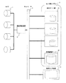
図1は、本発明の第1の実施の形態の映像ネットワークシステムの構成を示すブロック図である。
<First Embodiment>
FIG. 1 is a block diagram showing a configuration of a video network system according to the first embodiment of this invention.
第1の実施の形態の映像ネットワークシステムは、複数のカメラ1、センタ側システム2、監視モニタ装置3、ネットワーク4及び登録計算機5を備える。
The video network system according to the first embodiment includes a plurality of
カメラ1は、レンズを含む光学系、映像を電気信号に変換する撮像部及びネットワークインターフェースを備える。例えば、カメラ1は、IPネットワークに直接接続可能なIPカメラを用いることができる。カメラ1は、撮影対象領域に設置され、撮影対象領域の映像を撮影し、撮影された映像データを登録用計算機5に送る。
The
登録用計算機5は、プロセッサ、メモリ、記憶装置及びネットワークインターフェースを備える計算機である。登録用計算機5は、画像登録プログラム100(図2参照)を実行することによって、カメラ1によって撮影された映像データから画像特徴量を抽出する。抽出される画像特徴量の抽出は動き検出、顔検出の技術が用いられ、予め定められた動きや、予め定められた顔を撮影された映像データから抽出してもよい。さらに、登録用計算機5は、画像登録プログラム100を実行することによって、撮影された映像データから低精細度の映像データ(サムネイルデータ)を生成する。そして、抽出された画像特徴量及び生成された低精細度映像データはネットワーク4を介して検索サーバ21に送られる。
The
図には、1台の登録用計算機5を図示したが、複数の登録用計算機5が備わってもよい。また、1台の登録用計算機5に接続されるカメラの数は、登録用計算機5に備わるリソースの容量によって任意に選択することができる。
Although one
センタ側システム2は、少なくとも一台の検索サーバ21及び映像蓄積サーバ22を備える。
The
検索サーバ21は、プロセッサ、メモリ、記憶装置及びネットワークインターフェースを備える計算機であり、カメラ1によって撮影された映像データの画像特徴量及び低精細度映像データを記憶装置に格納する。そして、検索サーバ21は、監視モニタ装置3からの検索要求に基づいて、映像蓄積サーバ22に蓄積された映像データの特徴量を検索し、検索結果(映像データの識別子及び低精細度映像データ)を監視モニタ装置3に返信する。なお、複数の検索サーバ21が、検索サーバ群を構成してもよい。また、検索サーバ21は、ネットワーク4に対して映像データの転送帯域を制御する信号を送信してもよい。
The
映像蓄積サーバ22は、プロセッサ、メモリ、記憶装置及びネットワークインターフェースを備える計算機であり、映像蓄積サーバプログラム220(図2参照)を実行する。すなわち、映像蓄積サーバ22は、登録用計算機5に対して高精細度画像要求を送信し、カメラ1によって撮影された映像(動画)データを取得し、取得した映像データを記憶装置に格納する。また、映像蓄積サーバ22は、監視モニタ装置3からの要求に基づいて、格納されている映像データを監視モニタ装置3に送信する。図には、1台の映像蓄積サーバ22を図示したが、複数の映像蓄積サーバ22が備わってもよい。
The
監視モニタ装置3は、プロセッサ、メモリ、ネットワークインターフェース、操作部、及び表示部を備え、本映像ネットワークシステムの運用者が操作する計算機である。監視モニタ装置3は、複数のカメラ1によって撮影された映像データから選択された又は全ての映像データを表示部(画面)に表示する。
The
例えば、監視モニタ装置3は、運用者が入力した検索要求を映像蓄積サーバ22に送信し、当該検索要求と検索結果とを表示する。さらに、検索結果に対応する映像データ(高精細度データ)を監視モニタ装置3から取得し、取得した映像データを表示する。
For example, the
また、監視モニタ装置3は、カメラ1が撮影した映像データから抽出した画像特徴量が、予め定めた所定の条件に合致した場合、当該条件に合致した映像データを撮影したカメラ1からの映像データ(高精細度データ)をリアルタイムで表示する。なお、撮影領域に設置された他のセンサ(例えば、赤外線センサ)を用いて、高精細度映像データの表示条件を判定してもよい。図には、1台の監視モニタ装置3を図示したが、複数の監視モニタ装置3が備わってもよい。
In addition, when the image feature amount extracted from the video data captured by the
カメラ1、検索サーバ21、映像蓄積サーバ22及び監視モニタ装置3は、ネットワーク4を介して接続されている。例えば、ネットワーク4は、TCP/IPパケットを転送可能なIPネットワークを用いることができる。
The
図2は、本発明の第1の実施の形態の映像ネットワークシステムの映像配信処理を示す説明図である。 FIG. 2 is an explanatory diagram illustrating video distribution processing of the video network system according to the first embodiment of this invention.
登録用計算機5は、画像登録プログラム100を実行する。画像登録プログラム100では、映像取得スレッド110、映像配信スレッド120、検索用情報登録スレッド140(図3参照)の三つのスレッドが並列に実行される。なお、各スレッドは繰り返し実行される。
The
映像蓄積サーバ22は、映像蓄積サーバプログラム220を実行する。映像蓄積サーバプログラム220は繰り返し実行される。
The
まず、映像取得スレッド110の処理について説明する。
First, the processing of the
映像取得スレッド110では、カメラ1の撮像素子11が取得した映像データを取得して、メモリに設けられたバッファにフレーム画像として画像データを格納する(111)。
The
次に、バッファに格納されたフレーム画像を用いて、フレーム画像系列上における各画素値の平均値を画素値とする背景画像を計算する。そして、背景画像を新たに計算された背景画像に更新する(112)。 Next, using the frame image stored in the buffer, a background image having the pixel value as the average value of the pixel values on the frame image series is calculated. Then, the background image is updated to the newly calculated background image (112).
次に、フレーム画像と背景画像の差を画素値とする背景差分画像を計算する。そして、計算された背景差分画像及びフレーム画像をスレッド間通信130によって送信されるデータに設定する(113)。 Next, a background difference image having a pixel value as a difference between the frame image and the background image is calculated. Then, the calculated background difference image and frame image are set as data transmitted by the inter-thread communication 130 (113).
その後、映像配信スレッド120は、スレッド間通信(130)によって、フレーム画像を取得する。
Thereafter, the
検索用情報登録スレッド120では、映像蓄積サーバ22からの要求を受信すると(121)、スレッド間通信130によって送信されたデータから最新のフレーム画像を取得し(122)、取得したフレーム画像を映像蓄積サーバに送信する(123)。
When receiving the request from the video storage server 22 (121), the search
次に、映像蓄積サーバ22によって実行される映像蓄積サーバプログラム220について説明する。
Next, the video
映像蓄積サーバ22は、所定のタイミングで(例えば、所定の時間間隔で、他のシステムによってイベントが検出されたときに)、登録用計算機5に対して高精細度画像要求を送信する(221)。そして、カメラ1によって撮影された映像データを取得すると(222)、取得した映像データの時間間隔を調整し、取得した映像データを記憶装置に格納する(223)。この映像データの時間間隔の調整は、登録用計算機5から取得した映像データに付された情報(例えば、当該映像データのフレームレート)を参照して、映像蓄積サーバ22に記録される形式のフレームレートに合わせた映像データの形式に変換して、変換された映像データを記録する。なお、映像データのフレームレートを高レートから低レートに変換する場合は、余剰なフレームを削除すればよい。一方、映像データのフレームレートを低レートから高レートに変換する場合は、前後の画像を不足するフレームとするか、不足するフレームを補完してもよい。
The
このように時間間隔が調整された映像データを記憶装置に格納するので、異なるフレームレートの画像データを統一した形式で格納することができる。 Since the video data whose time interval is adjusted in this way is stored in the storage device, image data with different frame rates can be stored in a unified format.
図3は、本発明の第1の実施の形態の映像ネットワークシステムの検索用情報登録処理の概要を示す説明図である。 FIG. 3 is an explanatory diagram showing an overview of search information registration processing of the video network system according to the first embodiment of this invention.
まず、映像取得スレッド110の処理は、図2で前述したものと同じである。
First, the processing of the
検索用情報登録スレッド140では、スレッド間通信130によって送られたデータ(フレーム画像、背景差分画像)を取得すると(141)、イベント検出処理142(図4)によってイベントを検出する。そして、イベントが検出されない場合は(143で”N”)、ステップ141に戻り、次の画像を取得する。一方、イベントが検出された場合は(143で”Y”)、画像特徴量を抽出する(144)。
When the search
その後、抽出された特徴量及び原映像データの識別子を含む検索用情報登録要求(図5の2001)を検索サーバ21に送る(145)。なお、検索用情報登録要求には、原映像データの識別子ではなく、原映像データを撮影したカメラ1の識別子を含んでもよい。そして、検索サーバ21から検索用情報の登録確認通知を受信すると(146)、ステップ141に戻り、次の画像を取得する。
Thereafter, a search information registration request (2001 in FIG. 5) including the extracted feature amount and the identifier of the original video data is sent to the search server 21 (145). The search information registration request may include the identifier of the
次に、検索サーバ21によって実行される検索サーバプログラム210について説明する。
Next, the
検索サーバ21は、登録用計算機5から検索用情報登録要求を受信した場合に(211)、受信した検索用情報(画像特徴量及び映像データの識別子)を記憶装置に格納する(212)。その後、登録用計算機5に、検索用情報の登録確認通知を送る(213)。なお、図5で後述するように、登録用計算機5は、検索用情報の格納後に、登録イベント通知を監視モニタ装置3に送る。
When receiving the search information registration request from the registration computer 5 (211), the
図4は、本発明の第1の実施の形態の映像ネットワークシステムの検索用情報登録処理の詳細を示すフローチャートである。 FIG. 4 is a flowchart showing details of search information registration processing of the video network system according to the first embodiment of this invention.
検索用情報登録スレッド処理は、まず、スレッド間通信130によって送られたフレーム画像及び背景差分画像を取得すると(1001)、取得した画像からイベントを検出する(1002)。具体的には、背景差分画像の画素値の2乗和を求め、求められた2乗和と所定の閾値とを比較することによって、動き成分の有無を判定する。その結果、求められた画素値の2乗和が大きい(動き成分が存在する)場合には、イベントが検出されたと判定する。
In the search information registration thread process, first, when the frame image and the background difference image sent by the
なお、動き成分の有無によらず、顔検出を用いてイベントを検出してもよい。顔検出の方法は、ステップ1003で後述する方法を用い、予め登録された顔と一致する顔が画像中に検出された場合に、イベントが検出されたと判定してもよい。
Note that an event may be detected using face detection regardless of the presence or absence of a motion component. As a face detection method, a method described later in
そして、イベントが検出されない場合は、ステップ1001に戻り、次の画像を取得する。一方、イベントが検出された場合は、イベントが検出されたフレーム画像から画像特徴量を検出するために、ステップ1003に進む。このように、特徴量の検出前に、動き成分の有無によってイベントを検出することによって、演算量が大きい画像特徴検出処理を頻繁に実行する必要がなくなり、全体として演算量を抑制することができる。 If no event is detected, the process returns to step 1001 to acquire the next image. On the other hand, if an event is detected, the process proceeds to step 1003 in order to detect an image feature amount from the frame image in which the event is detected. Thus, by detecting an event based on the presence or absence of a motion component before detecting a feature amount, it is not necessary to frequently perform image feature detection processing with a large computation amount, and the computation amount can be suppressed as a whole. .
ステップ1003では、イベントが検出されたフレーム画像から顔領域を検出する。顔検出は、オープンソースのライブラリである”OpenCV”を用いることができる。この”OpenCV”はインテル社のホームページが詳しい。
In
そして、1以上の顔領域が検出された場合に(1004で”Y”)、検出された各顔領域の画像特徴量を抽出する(1005)。顔領域の画像特徴量の検出は、エッジパターン特徴量を用いるとよい。エッジパターン特徴量を抽出するために、まず、予め複数特徴的なエッジパターンを設定する。そして、顔画像を格子状に構図分割を行い、各領域内に含まれるエッジパターン数を数える。数えられたエッジパターン数のヒストグラムを生成し、予め設定されたエッジパターン数を次元とする多次元ベクトルを生成することによって、顔画像特徴量を生成する。なお、顔に固有の目、鼻及び/又は口等の部分に着目して、顔画像特徴量を生成してもよい。 When one or more face areas are detected (“Y” in 1004), the image feature amount of each detected face area is extracted (1005). The detection of the image feature amount of the face area may be performed using the edge pattern feature amount. In order to extract edge pattern feature amounts, first, a plurality of characteristic edge patterns are set in advance. Then, the face image is divided into a lattice pattern, and the number of edge patterns included in each region is counted. A histogram of the counted number of edge patterns is generated, and a face image feature amount is generated by generating a multi-dimensional vector whose dimension is a preset number of edge patterns. Note that the facial image feature quantity may be generated by paying attention to parts such as eyes, nose and / or mouth unique to the face.
次に、イベントが検出されたフレーム画像から移動体領域を検出する(1006)。移動体検出には、フレーム間差分法及び/又は背景差分法を用いることができる。フレーム間差分法は、1〜数フレーム前の画像と現在のフレーム画像の差を求め、移動体の領域を検出する。背景差分法は、現在のフレーム画像と予め作成しておいた背景の画像との差を求め、移動体の領域を検出する。 Next, the moving object region is detected from the frame image in which the event is detected (1006). For the moving object detection, an interframe difference method and / or a background difference method can be used. In the interframe difference method, a difference between an image one to several frames before and a current frame image is obtained, and a region of a moving object is detected. In the background subtraction method, a difference between a current frame image and a background image created in advance is obtained, and a region of a moving object is detected.
そして、1以上の移動体領域が検出された場合に(1007で”Y”)、検出された各移動体領域の画像特徴量を抽出する(1008)。移動体領域の画像特徴量を求めるためには、色情報に基づいた全体画像特徴量を検出領域から抽出するとよい。具体的には、検出領域に対して格子状に構図分割を行い、分割された各領域の色ヒストグラムを生成する。そして、色ヒストグラムから生成される多次元ベクトルを、全体画像特徴量として用いる。なお、色情報ではなく輝度値及び明度値等の情報、又は、色、輝度値及び明度値を組み合わせたものを用いてもよい。 When one or more moving object areas are detected (“Y” in 1007), the image feature amount of each detected moving object area is extracted (1008). In order to obtain the image feature amount of the moving body region, it is preferable to extract the entire image feature amount based on the color information from the detection region. Specifically, composition division is performed on the detection area in a grid pattern, and a color histogram of each divided area is generated. Then, a multidimensional vector generated from the color histogram is used as the entire image feature amount. Note that information such as a luminance value and a lightness value instead of color information, or a combination of color, luminance value, and lightness value may be used.
その後、1以上の顔領域又は1以上の移動体領域が検出されたか否かを判定する(1009)。その結果、顔領域及び移動体領域のいずれも検出されない場合に(1009で”N”)、検出されたイベントは無効と判定し、画像特徴量を登録することなく、ステップ1001に戻り、次の画像を取得する。一方、1以上の顔領域又は1以上の移動体領域のいずれかが検出された場合に(1009で”Y”)、各領域の画像特徴量を含む検索用情報登録要求(図5の2001)を検索サーバ21に送信する(1010)。 Thereafter, it is determined whether one or more face areas or one or more moving body areas have been detected (1009). As a result, when neither the face area nor the moving body area is detected ("N" in 1009), the detected event is determined to be invalid, and the process returns to step 1001 without registering the image feature amount, Get an image. On the other hand, when either one or more face areas or one or more moving body areas are detected (“Y” in 1009), a search information registration request including the image feature amount of each area (2001 in FIG. 5). Is transmitted to the search server 21 (1010).
このように、動き成分によってイベントが検出されても、顔領域及び/又は移動体領域が検出されず、画像特徴量が抽出されない場合は、検索サーバ21に検索情報登録要求を送らないので、検索システムの負荷を抑制することができる。
Thus, even if an event is detected by a motion component, if a face area and / or moving body area is not detected and an image feature amount is not extracted, a search information registration request is not sent to the
図4に示した検索用情報登録処理では、顔領域及び移動体領域を検出したが、顔領域又は移動体領域の一方を検出して、検出された領域の画像特徴量を抽出してもよい。 In the search information registration process illustrated in FIG. 4, the face area and the moving body area are detected. However, one of the face area and the moving body area may be detected, and the image feature amount of the detected area may be extracted. .
図5は、本発明の第1の実施の形態の映像ネットワークシステムの動作を示す説明図である。 FIG. 5 is an explanatory diagram illustrating an operation of the video network system according to the first embodiment of this invention.
登録用計算機5は、カメラ1が取得した画像にイベントが検出されると、検索サーバ21に検索用情報登録要求2001を送信する。
When an event is detected in the image acquired by the
検索サーバ21は、登録用計算機5から検索用情報登録要求2001を受信した場合に(図4の211)、受信した検索用情報を記憶装置に格納する(図4の212)。その後、登録用計算機5に、登録イベント通知2002を監視モニタ装置3に送り、新たにデータが登録されたことを登録データの識別子とともに通知する。
When receiving the search
監視モニタ装置3は、受信した検索用情報に関する映像データの重要度を判定し、受信した検索用情報に関する映像データが重要であると判定した場合は、映像データの識別子を含む映像配信要求を映像蓄積サーバ22に送信する。
The
映像蓄積サーバ22は、映像配信要求を受信した場合に、受信した映像データの識別子に対応するカメラ1の最新映像を、要求元の監視モニタ装置3に送信する(2003)。
When receiving the video distribution request, the
監視モニタ装置3は、映像蓄積サーバ22から受信した映像データを動画像として表示する。
The
前述したように、本発明の第1の実施の形態では、登録用計算機5は、カメラ1によって撮影された映像から検索用情報を生成し、前記生成された検索用情報を検索サーバ21に送信する。検索サーバは、登録用計算機5から受信した検索用情報を記憶装置に格納し、格納が行われたことをイベントとして監視モニタ装置3に送信する。また、映像蓄積サーバ22は、所定のタイミングで、カメラ1が取得した映像データを登録用計算機5に要求する。登録用計算機5は、映像蓄積サーバ22からの要求に従って、カメラ1によって撮影された映像を送信する。
As described above, in the first embodiment of the present invention, the
よって、複数のカメラを含む映像ネットワークシステムにおいて、適切な負荷分散を図ることができる。このような負荷分散によって、カメラの数が増加してもシステムを構成する各装置(サーバ、計算機)を増加することによって、システムの負荷及びネットワークの負荷が逼迫することがなく、システムのスケーラビリティを向上させることができる。 Therefore, appropriate load distribution can be achieved in a video network system including a plurality of cameras. Such load balancing increases the number of devices (servers, computers) that make up the system even if the number of cameras increases, thereby reducing system load and network load without increasing system scalability. Can be improved.
また、高精細度の動画像データを監視モニタ装置3に必要に応じて配信するので、ネットワークの負荷の増大を抑制することができる。さらに、映像蓄積サーバ22が、高精細度の動画像データの映像蓄積サーバ22への送信タイミングを制御するので、ネットワークの負荷の増大を抑制することができる。
Moreover, since high-definition moving image data is distributed to the
また、監視モニタ装置3は、検索サーバ21から受信した検索用情報に関連する映像の要否(重要度)を判定し、受信した検索用情報に関連する映像が必要と判定した場合に、映像蓄積サーバ22に当該検索用情報に関連する映像を要求する。映像蓄積サーバ22は、監視モニタ装置3からの映像配信要求に従って、要求された映像データを要求元の監視モニタ装置3に送信する。監視モニタ装置3は、映像蓄積サーバ22から取得した映像データを表示する。
Further, the
よって、ネットワークの負荷を増大させることなく、履歴情報(過去の映像データ)とリアルタイム情報(現在の映像データ)とをシームレスに検索及び表示することができる。 Therefore, history information (past video data) and real-time information (current video data) can be seamlessly searched and displayed without increasing the network load.
さらに、カメラ側の登録用計算機5で顔検出、移動体検出によって検索対象となるフレーム画像を絞り込むので、検索サーバに集まる情報を抑制し、検索サーバ21の負荷を軽減することができる。
Further, since the
さらに、カメラ側の登録用計算機5で画像特徴量を抽出するので、検索サーバ21の負荷を軽減することができる。
Furthermore, since the image feature amount is extracted by the
さらに、カメラ1が取得した映像データを処理する登録用計算機5をカメラ1と別個に設けたので、カメラ1に高度な機能を必要とせず、低機能かつ低価格な市販品のカメラを用いてシステムを構成することができる。
Furthermore, since the
<第2の実施の形態>
図6は、本発明の第2の実施の形態の映像ネットワークシステムの構成を示すブロック図である。
<Second Embodiment>
FIG. 6 is a block diagram illustrating a configuration of a video network system according to the second embodiment of this invention.
第2の実施の形態は、前述した第1の実施の形態と異なり、登録用計算機5を備えない。第2の実施の形態では、カメラ1に備わる映像処理部が、第1の実施の形態の登録用計算機5と同じ機能をする。
Unlike the first embodiment described above, the second embodiment does not include the
具体的には、第2の実施の形態の映像ネットワークシステムは、複数のカメラ1、センタ側システム2、監視モニタ装置3及びネットワーク4を備える。
Specifically, the video network system according to the second embodiment includes a plurality of
カメラ1は、レンズを含む光学系、映像を電気信号に変換する撮像部、撮影された映像データを処理する映像処理部及びネットワークインターフェースを備える。例えば、カメラ1は、IPネットワークに直接接続可能なIPカメラを用いることができる。カメラ1は、撮影対象領域に設置され、撮影対象領域の映像を撮影し、映像蓄積サーバ22からの高精細度画像の要求に基づいて、撮影された映像データをネットワーク4を介して映像蓄積サーバ22に送る。
The
また、カメラ1の映像処理部は、プロセッサ及びメモリを備え、撮影された映像データから画像特徴量を抽出する。抽出される画像特徴量の抽出は動き検出、顔検出の技術が用いられ、予め定められた動きや、予め定められた顔が撮影された映像データから抽出される。さらに、カメラ1の映像処理部は、撮影された映像データから低精細度の映像データを生成する。そして、抽出された画像特徴量及び生成された低精細度映像データはネットワーク4を介して検索サーバ21に送られる。
The video processing unit of the
すなわち、前述した第1の実施の形態の登録用計算機5に代わって、カメラ1の映像処理部が画像登録プログラム100(図2、図3参照)を実行する。
That is, instead of the
センタ側システム2及び監視モニタ装置3は、前述した第1の実施の形態(図6)と同じである。なお、第2の実施の形態の映像蓄積サーバ22は、カメラ1に対して高精細度画像要求を送信する。
The
カメラ1、検索サーバ21、映像蓄積サーバ22及び監視モニタ装置3は、ネットワーク4を介して接続されている。例えば、ネットワーク4は、TCP/IPパケットを転送可能なIPネットワークを用いることができる。
The
前述したように、本発明の第2の実施の形態では、カメラ1が登録用計算機5の機能を含めた(カメラ1の映像処理部で登録用計算機5と同じ処理をする)ので、前述した第1の実施の形態より処理をさらに分散化することができ、システムのスケーラビリティを向上させることができる。
As described above, in the second embodiment of the present invention, the
1 カメラ
2 センタ側システム
21 検索サーバ
22 映像蓄積サーバ
3 監視モニタ装置
4 ネットワーク
5 登録用計算機
DESCRIPTION OF
Claims (12)
前記カメラによって撮影された映像の検索用情報を生成する情報生成装置と、
前記カメラによって撮影された映像を検索する検索装置と、を備え、
前記情報生成装置は、前記カメラによって撮影された映像を取得し、所定のイベントが検出された場合には、前記取得した映像から生成した画像特徴量及び低精細度画像を含む検索用情報を前記検索装置に送信し、
前記検索装置は、前記情報生成装置から受信した検索用情報を記憶装置に格納し、前記格納された検索用情報を前記モニタ装置に送信し、
前記情報生成装置は、前記カメラによって撮影された映像から所定のイベントが検出されない場合には、前記検索用情報を前記検索装置に送信しないことを特徴とする映像ネットワークシステム。 A video network system comprising a plurality of cameras that capture video and a monitor device that displays video captured by the camera,
An information generating device for generating search information for video shot by the camera;
A search device for searching for video captured by the camera,
The information generation device acquires a video captured by the camera, and when a predetermined event is detected , the information generation device stores search information including an image feature amount and a low-definition image generated from the acquired video. To the search device,
The search device stores search information received from the information generation device in a storage device, and transmits the stored search information to the monitor device ,
The video network system , wherein the information generation device does not transmit the search information to the search device when a predetermined event is not detected from the video taken by the camera .
前記モニタ装置は、前記検索用装置から受信した検索用情報に基づいて、前記検索用情報に関連する映像の要否を判定し、前記検索用情報に関連する映像が必要と判定した場合に、前記映像蓄積装置に当該検索用情報に関連する映像を要求し、 The monitor device determines whether the video related to the search information is necessary based on the search information received from the search device, and determines that the video related to the search information is necessary. Requesting a video related to the search information from the video storage device;
前記映像蓄積装置は、前記モニタ装置からの映像の要求に従って、要求された映像データを要求元の前記モニタ装置に送信し、 The video storage device transmits the requested video data to the requesting monitor device according to the video request from the monitor device,
前記モニタ装置は、前記映像蓄積装置から取得した映像データを表示することを特徴とする請求項1に記載の映像ネットワークシステム。 The video network system according to claim 1, wherein the monitor device displays video data acquired from the video storage device.
前記映像蓄積装置は、所定のタイミングで、前記カメラによって撮影された映像を前記情報生成装置に要求し、 The video storage device requests the information generation device for a video shot by the camera at a predetermined timing,
前記情報生成装置は、前記映像蓄積装置からの要求に従って、前記カメラによって撮影された映像を送信することを特徴とする請求項1に記載の映像ネットワークシステム。 2. The video network system according to claim 1, wherein the information generation device transmits a video shot by the camera in accordance with a request from the video storage device.
前記情報生成装置は、前記カメラによって撮影された映像から動き成分を検出し、前記動き成分が検出されない場合に、前記検索用情報を前記検索装置に送信しないことを特徴とする請求項1に記載の映像ネットワークシステム。 2. The information generation device according to claim 1, wherein the information generation device detects a motion component from an image captured by the camera, and does not transmit the search information to the search device when the motion component is not detected. Video network system.
前記情報生成装置は、前記カメラによって撮影された映像から顔領域画像を検出し、前記顔領域画像が検出されない場合に、前記検索用情報を前記検索装置に送信しないことを特徴とする請求項1に記載の映像ネットワークシステム。 The information generation apparatus detects a face area image from an image captured by the camera, and does not transmit the search information to the search apparatus when the face area image is not detected. The video network system described in 1.
前記カメラによって撮影された映像から顔領域を検出し、前記検出された顔領域の画像特徴量を抽出し、 A face area is detected from an image captured by the camera, and an image feature amount of the detected face area is extracted;
前記カメラによって撮影された映像から移動体領域を検出し、前記検出された移動体領域の画像特徴量を抽出し、 Detecting a moving body region from the video imaged by the camera, and extracting an image feature amount of the detected moving body region;
前記抽出された画像特徴量を前記検索用情報とすることを特徴とする請求項5又は6に記載の映像ネットワークシステム。 The video network system according to claim 5 or 6, wherein the extracted image feature amount is used as the search information.
前記カメラによって撮影された映像から動き成分が検出された場合に、前記顔領域及び前記移動体領域を検出し、 When a motion component is detected from an image captured by the camera, the face area and the moving body area are detected,
前記動き成分が検出されても、前記顔領域及び前記移動体領域のいずれも検出されない場合に、前記検索用情報を前記検索装置に送信しないことを特徴とする請求項7に記載の映像ネットワークシステム。 8. The video network system according to claim 7, wherein, even if the motion component is detected, if neither the face area nor the moving body area is detected, the search information is not transmitted to the search device. 9. .
前記情報生成装置は、映像蓄積装置からの要求に従って、前記カメラによって撮影された映像を送信し、 The information generation device transmits a video shot by the camera according to a request from a video storage device,
前記情報生成装置は、さらに、前記カメラによって撮影された映像を取得し、所定のイベントが検出された場合には、前記取得した映像から生成した画像特徴量及び低精細度画像を含む検索用情報を前記検索装置に送信し、 The information generation device further acquires video captured by the camera, and when a predetermined event is detected, information for search including an image feature amount and a low-definition image generated from the acquired video To the search device,
前記検索装置は、前記情報生成装置から受信した検索用情報を格納し、前記検索用情報を格納したことを前記モニタ装置に通知し、 The search device stores the search information received from the information generation device, notifies the monitor device that the search information has been stored,
前記モニタ装置は、前記検索用装置から受信した通知に基づいて、前記検索用情報に関連する映像を表示し、 The monitor device displays a video related to the search information based on the notification received from the search device;
前記情報生成装置は、前記カメラによって撮影された映像から所定のイベントが検出されない場合には、前記検索用情報を前記検索装置に送信しないことを特徴とする映像データ管理方法。 The video data management method, wherein the information generation device does not transmit the search information to the search device when a predetermined event is not detected from the video taken by the camera.
前記映像蓄積装置は、所定のタイミングで、前記カメラによって撮影された映像を前記情報生成装置に要求し、 The video storage device requests the information generation device for a video shot by the camera at a predetermined timing,
前記情報生成装置は、前記映像蓄積装置からの要求に従って、前記カメラによって撮影された映像を送信し、 The information generation device transmits a video shot by the camera according to a request from the video storage device,
前記情報生成装置は、さらに、前記カメラによって撮影された映像を取得し、所定のイベントが検出された場合には、前記取得した映像から生成した画像特徴量及び低精細度画像を含む検索用情報を前記検索装置に送信し、 The information generation device further acquires video captured by the camera, and when a predetermined event is detected, information for search including an image feature amount and a low-definition image generated from the acquired video To the search device,
前記検索装置は、前記情報生成装置から受信した検索用情報を格納し、前記格納された検索用情報を前記モニタ装置に送信し、 The search device stores search information received from the information generation device, transmits the stored search information to the monitor device,
前記モニタ装置は、前記検索用装置から受信した検索用情報に基づいて、前記検索用情報に関連する映像の要否を判定し、前記検索用情報に関連する映像が必要と判定した場合に、前記映像蓄積装置に当該検索用情報に関連する映像を要求し、 The monitor device determines whether the video related to the search information is necessary based on the search information received from the search device, and determines that the video related to the search information is necessary. Requesting a video related to the search information from the video storage device;
前記映像蓄積装置は、前記モニタ装置からの映像の要求に従って、要求された映像データを要求元の前記モニタ装置に送信し、 The video storage device transmits the requested video data to the requesting monitor device according to the video request from the monitor device,
前記モニタ装置は、前記映像蓄積装置から取得した映像データを表示し、 The monitor device displays video data acquired from the video storage device;
前記情報生成装置は、前記カメラによって撮影された映像から所定のイベントが検出されない場合には、前記検索用情報を前記検索装置に送信しないことを特徴とする映像データ管理方法。 The video data management method, wherein the information generation device does not transmit the search information to the search device when a predetermined event is not detected from the video taken by the camera.
Priority Applications (3)
| Application Number | Priority Date | Filing Date | Title |
|---|---|---|---|
| JP2008007934A JP5213105B2 (en) | 2008-01-17 | 2008-01-17 | Video network system and video data management method |
| CN2009100016066A CN101489116B (en) | 2008-01-17 | 2009-01-05 | Video network system and video data management method |
| US12/350,512 US9277165B2 (en) | 2008-01-17 | 2009-01-08 | Video surveillance system and method using IP-based networks |
Applications Claiming Priority (1)
| Application Number | Priority Date | Filing Date | Title |
|---|---|---|---|
| JP2008007934A JP5213105B2 (en) | 2008-01-17 | 2008-01-17 | Video network system and video data management method |
Publications (2)
| Publication Number | Publication Date |
|---|---|
| JP2009171296A JP2009171296A (en) | 2009-07-30 |
| JP5213105B2 true JP5213105B2 (en) | 2013-06-19 |
Family
ID=40876570
Family Applications (1)
| Application Number | Title | Priority Date | Filing Date |
|---|---|---|---|
| JP2008007934A Active JP5213105B2 (en) | 2008-01-17 | 2008-01-17 | Video network system and video data management method |
Country Status (3)
| Country | Link |
|---|---|
| US (1) | US9277165B2 (en) |
| JP (1) | JP5213105B2 (en) |
| CN (1) | CN101489116B (en) |
Families Citing this family (32)
| Publication number | Priority date | Publication date | Assignee | Title |
|---|---|---|---|---|
| KR100601933B1 (en) * | 2003-11-18 | 2006-07-14 | 삼성전자주식회사 | Method and apparatus of human detection and privacy protection method and system employing the same |
| KR100885734B1 (en) * | 2007-12-17 | 2009-02-26 | 한국전자통신연구원 | System and method for image information processing |
| US9721148B2 (en) | 2007-12-31 | 2017-08-01 | Applied Recognition Inc. | Face detection and recognition |
| CN104866553A (en) | 2007-12-31 | 2015-08-26 | 应用识别公司 | Method, system, and computer program for identification and sharing of digital images with face signatures |
| US9639740B2 (en) | 2007-12-31 | 2017-05-02 | Applied Recognition Inc. | Face detection and recognition |
| CN101646070B (en) * | 2009-07-30 | 2012-09-19 | 杭州联图科技有限公司 | Novel intelligent security-protecting and monitoring method and special equipment thereof |
| JP5730518B2 (en) | 2010-08-27 | 2015-06-10 | 株式会社日立国際電気 | Specific person detection system and specific person detection method |
| US8575328B2 (en) | 2010-12-14 | 2013-11-05 | The United States Of America, As Represented By The Secretary Of Agriculture | Formicidae (ant) control using double-stranded RNA constructs |
| US9552376B2 (en) | 2011-06-09 | 2017-01-24 | MemoryWeb, LLC | Method and apparatus for managing digital files |
| US8548207B2 (en) | 2011-08-15 | 2013-10-01 | Daon Holdings Limited | Method of host-directed illumination and system for conducting host-directed illumination |
| US9202105B1 (en) | 2012-01-13 | 2015-12-01 | Amazon Technologies, Inc. | Image analysis for user authentication |
| JP2013192154A (en) * | 2012-03-15 | 2013-09-26 | Omron Corp | Monitoring device, reliability calculation program and reliability calculation method |
| US8766914B2 (en) | 2012-06-26 | 2014-07-01 | Intel Corporation | Method and apparatus for measuring audience size for a digital sign |
| JP2015164031A (en) * | 2014-01-30 | 2015-09-10 | 株式会社リコー | image display system |
| JP6369973B2 (en) * | 2014-03-25 | 2018-08-08 | 株式会社日立国際電気 | Information communication system and information communication method |
| EP3158505B1 (en) * | 2014-06-18 | 2023-06-07 | Trax Technology Solutions Pte Ltd. | A method and a system for object recognition |
| US10402777B2 (en) | 2014-06-18 | 2019-09-03 | Trax Technology Solutions Pte Ltd. | Method and a system for object recognition |
| US10803160B2 (en) | 2014-08-28 | 2020-10-13 | Facetec, Inc. | Method to verify and identify blockchain with user question data |
| US10698995B2 (en) | 2014-08-28 | 2020-06-30 | Facetec, Inc. | Method to verify identity using a previously collected biometric image/data |
| CA3186147A1 (en) | 2014-08-28 | 2016-02-28 | Kevin Alan Tussy | Facial recognition authentication system including path parameters |
| US10614204B2 (en) | 2014-08-28 | 2020-04-07 | Facetec, Inc. | Facial recognition authentication system including path parameters |
| US10915618B2 (en) | 2014-08-28 | 2021-02-09 | Facetec, Inc. | Method to add remotely collected biometric images / templates to a database record of personal information |
| US11256792B2 (en) | 2014-08-28 | 2022-02-22 | Facetec, Inc. | Method and apparatus for creation and use of digital identification |
| CN105574506B (en) * | 2015-12-16 | 2020-03-17 | 深圳市商汤科技有限公司 | Intelligent face pursuit system and method based on deep learning and large-scale clustering |
| US20170254876A1 (en) * | 2016-03-07 | 2017-09-07 | Symbol Technologies, Llc | Arrangement for, and method of, sensing targets with improved performance in a venue |
| USD987653S1 (en) | 2016-04-26 | 2023-05-30 | Facetec, Inc. | Display screen or portion thereof with graphical user interface |
| JP6692736B2 (en) * | 2016-12-01 | 2020-05-13 | 株式会社日立製作所 | Video surveillance system, control method of video surveillance system, and video surveillance device |
| JP7118679B2 (en) * | 2018-03-23 | 2022-08-16 | キヤノン株式会社 | VIDEO RECORDING DEVICE, VIDEO RECORDING METHOD AND PROGRAM |
| CN108733821A (en) * | 2018-05-22 | 2018-11-02 | 武汉微创光电股份有限公司 | A kind of distribution of monitor video sectional drawing and methods of exhibiting and system |
| US10936178B2 (en) | 2019-01-07 | 2021-03-02 | MemoryWeb, LLC | Systems and methods for analyzing and organizing digital photos and videos |
| JP7360841B2 (en) * | 2019-08-09 | 2023-10-13 | 株式会社日立ソリューションズ | X-ray image processing system, method, and program |
| JP2022089447A (en) * | 2020-12-04 | 2022-06-16 | 株式会社東芝 | Information processing system |
Family Cites Families (40)
| Publication number | Priority date | Publication date | Assignee | Title |
|---|---|---|---|---|
| US5012522A (en) * | 1988-12-08 | 1991-04-30 | The United States Of America As Represented By The Secretary Of The Air Force | Autonomous face recognition machine |
| US5917958A (en) * | 1996-10-31 | 1999-06-29 | Sensormatic Electronics Corporation | Distributed video data base with remote searching for image data features |
| CA2199999A1 (en) * | 1997-03-14 | 1998-09-14 | Peter Johann Kielland | Parking regulation enforcement system |
| US6185314B1 (en) * | 1997-06-19 | 2001-02-06 | Ncr Corporation | System and method for matching image information to object model information |
| US6970183B1 (en) * | 2000-06-14 | 2005-11-29 | E-Watch, Inc. | Multimedia surveillance and monitoring system including network configuration |
| US7131136B2 (en) * | 2002-07-10 | 2006-10-31 | E-Watch, Inc. | Comprehensive multi-media surveillance and response system for aircraft, operations centers, airports and other commercial transports, centers and terminals |
| US6583813B1 (en) * | 1998-10-09 | 2003-06-24 | Diebold, Incorporated | System and method for capturing and searching image data associated with transactions |
| JP3607566B2 (en) | 2000-04-07 | 2005-01-05 | 日本電信電話株式会社 | Multipoint information monitoring apparatus and method |
| US6504479B1 (en) * | 2000-09-07 | 2003-01-07 | Comtrak Technologies Llc | Integrated security system |
| US8564661B2 (en) * | 2000-10-24 | 2013-10-22 | Objectvideo, Inc. | Video analytic rule detection system and method |
| US9892606B2 (en) * | 2001-11-15 | 2018-02-13 | Avigilon Fortress Corporation | Video surveillance system employing video primitives |
| JP2002247566A (en) | 2000-11-30 | 2002-08-30 | Matsushita Electric Ind Co Ltd | Image receiver, image transmitter and image transmission system |
| JP2003030243A (en) * | 2001-07-16 | 2003-01-31 | Canon Inc | System for distributing image and information processor and methods thereof |
| JP4099973B2 (en) * | 2001-10-30 | 2008-06-11 | 松下電器産業株式会社 | Video data transmission method, video data reception method, and video surveillance system |
| US20030108334A1 (en) * | 2001-12-06 | 2003-06-12 | Koninklijke Philips Elecronics N.V. | Adaptive environment system and method of providing an adaptive environment |
| US7436887B2 (en) * | 2002-02-06 | 2008-10-14 | Playtex Products, Inc. | Method and apparatus for video frame sequence-based object tracking |
| US7369685B2 (en) * | 2002-04-05 | 2008-05-06 | Identix Corporation | Vision-based operating method and system |
| US6975346B2 (en) * | 2002-06-27 | 2005-12-13 | International Business Machines Corporation | Method for suspect identification using scanning of surveillance media |
| US7382896B2 (en) * | 2002-08-13 | 2008-06-03 | Hitachi Kokusai Electric Inc. | Object detection method and apparatus which perform object detection using set parameters |
| JP4568009B2 (en) * | 2003-04-22 | 2010-10-27 | パナソニック株式会社 | Monitoring device with camera cooperation |
| US20040233983A1 (en) * | 2003-05-20 | 2004-11-25 | Marconi Communications, Inc. | Security system |
| JP4380252B2 (en) * | 2003-07-22 | 2009-12-09 | ソニー株式会社 | Imaging apparatus and imaging method |
| US7280753B2 (en) * | 2003-09-03 | 2007-10-09 | Canon Kabushiki Kaisha | Display apparatus, image processing apparatus, and image processing system |
| US20050177859A1 (en) * | 2004-02-09 | 2005-08-11 | Valentino Henry Iii | Video surveillance system and methods of use and doing business |
| JP4789511B2 (en) * | 2004-06-04 | 2011-10-12 | キヤノン株式会社 | Status monitoring device and status monitoring system |
| US20050285941A1 (en) * | 2004-06-28 | 2005-12-29 | Haigh Karen Z | Monitoring devices |
| JP4533708B2 (en) * | 2004-09-17 | 2010-09-01 | 富士フイルム株式会社 | Surveillance camera system, control device for surveillance camera system, and control method |
| US7746378B2 (en) * | 2004-10-12 | 2010-06-29 | International Business Machines Corporation | Video analysis, archiving and alerting methods and apparatus for a distributed, modular and extensible video surveillance system |
| JP4517288B2 (en) * | 2004-12-17 | 2010-08-04 | 富士ゼロックス株式会社 | Image processing apparatus, image processing method, and program thereof |
| US20060238616A1 (en) * | 2005-03-31 | 2006-10-26 | Honeywell International Inc. | Video image processing appliance manager |
| US7760908B2 (en) * | 2005-03-31 | 2010-07-20 | Honeywell International Inc. | Event packaged video sequence |
| JP2007020057A (en) * | 2005-07-11 | 2007-01-25 | Matsushita Electric Ind Co Ltd | Device, method and program for monitoring intercommunication |
| US9363487B2 (en) * | 2005-09-08 | 2016-06-07 | Avigilon Fortress Corporation | Scanning camera-based video surveillance system |
| JP2007241377A (en) | 2006-03-06 | 2007-09-20 | Sony Corp | Retrieval system, imaging apparatus, data storage device, information processor, picked-up image processing method, information processing method, and program |
| US20070257986A1 (en) * | 2006-05-05 | 2007-11-08 | Ivanov Yuri A | Method for processing queries for surveillance tasks |
| US7907750B2 (en) * | 2006-06-12 | 2011-03-15 | Honeywell International Inc. | System and method for autonomous object tracking |
| US7791466B2 (en) * | 2007-01-12 | 2010-09-07 | International Business Machines Corporation | System and method for event detection utilizing sensor based surveillance |
| US8358342B2 (en) * | 2007-02-23 | 2013-01-22 | Johnson Controls Technology Company | Video processing systems and methods |
| US7460149B1 (en) * | 2007-05-28 | 2008-12-02 | Kd Secure, Llc | Video data storage, search, and retrieval using meta-data and attribute data in a video surveillance system |
| US8204273B2 (en) * | 2007-11-29 | 2012-06-19 | Cernium Corporation | Systems and methods for analysis of video content, event notification, and video content provision |
-
2008
- 2008-01-17 JP JP2008007934A patent/JP5213105B2/en active Active
-
2009
- 2009-01-05 CN CN2009100016066A patent/CN101489116B/en active Active
- 2009-01-08 US US12/350,512 patent/US9277165B2/en active Active
Also Published As
| Publication number | Publication date |
|---|---|
| CN101489116B (en) | 2012-07-18 |
| US9277165B2 (en) | 2016-03-01 |
| CN101489116A (en) | 2009-07-22 |
| US20090185784A1 (en) | 2009-07-23 |
| JP2009171296A (en) | 2009-07-30 |
Similar Documents
| Publication | Publication Date | Title |
|---|---|---|
| JP5213105B2 (en) | Video network system and video data management method | |
| US8280108B2 (en) | Image processing system, image processing method, and computer program | |
| WO2020094091A1 (en) | Image capturing method, monitoring camera, and monitoring system | |
| WO2020057355A1 (en) | Three-dimensional modeling method and device | |
| US8150103B2 (en) | Background modeling with feature blocks | |
| JP6077655B2 (en) | Shooting system | |
| KR101223424B1 (en) | Video motion detection | |
| US20110050901A1 (en) | Transmission apparatus and processing apparatus | |
| CN104883548B (en) | Monitor video face captures processing method and its system | |
| KR20150032630A (en) | Control method in image capture system, control apparatus and a computer-readable storage medium | |
| CN113228626B (en) | Video monitoring system and method | |
| CN112422909B (en) | Video behavior analysis management system based on artificial intelligence | |
| KR20210104979A (en) | apparatus and method for multi-channel image back-up based on event, and network surveillance camera system including the same | |
| JP5693147B2 (en) | Photographic interference detection method, interference detection device, and surveillance camera system | |
| JP6437217B2 (en) | Image output device, image management system, image processing method, and program | |
| JP6396682B2 (en) | Surveillance camera system | |
| CN205883437U (en) | Video monitoring device | |
| JP5865584B2 (en) | Specific person detection system and detection method | |
| CN111800604A (en) | Method and device for detecting human shape and human face data based on gun and ball linkage | |
| JPWO2018179119A1 (en) | Video analysis device, video analysis method, and program | |
| JP2012242970A (en) | Image processing device and control method therefor | |
| JP2008141700A (en) | Monitoring system and method, and program | |
| TWI613618B (en) | System and method for obtaining a motion region through image vector analysis | |
| Singh et al. | Motion detection application using web camera | |
| JPWO2017061239A1 (en) | Monitoring system |
Legal Events
| Date | Code | Title | Description |
|---|---|---|---|
| A621 | Written request for application examination |
Free format text: JAPANESE INTERMEDIATE CODE: A621 Effective date: 20100623 |
|
| A521 | Request for written amendment filed |
Free format text: JAPANESE INTERMEDIATE CODE: A523 Effective date: 20120309 |
|
| A977 | Report on retrieval |
Free format text: JAPANESE INTERMEDIATE CODE: A971007 Effective date: 20120702 |
|
| A131 | Notification of reasons for refusal |
Free format text: JAPANESE INTERMEDIATE CODE: A131 Effective date: 20120710 |
|
| A521 | Request for written amendment filed |
Free format text: JAPANESE INTERMEDIATE CODE: A523 Effective date: 20120904 |
|
| A131 | Notification of reasons for refusal |
Free format text: JAPANESE INTERMEDIATE CODE: A131 Effective date: 20121023 |
|
| A521 | Request for written amendment filed |
Free format text: JAPANESE INTERMEDIATE CODE: A523 Effective date: 20121212 |
|
| TRDD | Decision of grant or rejection written | ||
| A01 | Written decision to grant a patent or to grant a registration (utility model) |
Free format text: JAPANESE INTERMEDIATE CODE: A01 Effective date: 20130129 |
|
| A61 | First payment of annual fees (during grant procedure) |
Free format text: JAPANESE INTERMEDIATE CODE: A61 Effective date: 20130221 |
|
| R150 | Certificate of patent or registration of utility model |
Ref document number: 5213105 Country of ref document: JP Free format text: JAPANESE INTERMEDIATE CODE: R150 Free format text: JAPANESE INTERMEDIATE CODE: R150 |
|
| FPAY | Renewal fee payment (event date is renewal date of database) |
Free format text: PAYMENT UNTIL: 20160308 Year of fee payment: 3 |