JP5207614B2 - Controller, process control method and process control system - Google Patents
Controller, process control method and process control system Download PDFInfo
- Publication number
- JP5207614B2 JP5207614B2 JP2006289675A JP2006289675A JP5207614B2 JP 5207614 B2 JP5207614 B2 JP 5207614B2 JP 2006289675 A JP2006289675 A JP 2006289675A JP 2006289675 A JP2006289675 A JP 2006289675A JP 5207614 B2 JP5207614 B2 JP 5207614B2
- Authority
- JP
- Japan
- Prior art keywords
- value
- control signal
- control
- response
- update
- Prior art date
- Legal status (The legal status is an assumption and is not a legal conclusion. Google has not performed a legal analysis and makes no representation as to the accuracy of the status listed.)
- Active
Links
- 238000000034 method Methods 0.000 title claims description 308
- 238000004886 process control Methods 0.000 title claims description 73
- 230000008569 process Effects 0.000 claims description 244
- 230000004044 response Effects 0.000 claims description 75
- 238000005259 measurement Methods 0.000 claims description 55
- 230000005540 biological transmission Effects 0.000 claims description 26
- 230000000737 periodic effect Effects 0.000 claims description 24
- 238000004891 communication Methods 0.000 description 68
- 230000006870 function Effects 0.000 description 18
- 238000013461 design Methods 0.000 description 9
- 230000008901 benefit Effects 0.000 description 6
- 230000008859 change Effects 0.000 description 5
- 238000001514 detection method Methods 0.000 description 5
- 238000010586 diagram Methods 0.000 description 5
- 238000012369 In process control Methods 0.000 description 4
- 238000005516 engineering process Methods 0.000 description 4
- 238000010965 in-process control Methods 0.000 description 4
- 238000012546 transfer Methods 0.000 description 4
- 238000004364 calculation method Methods 0.000 description 3
- 238000011217 control strategy Methods 0.000 description 3
- 238000010348 incorporation Methods 0.000 description 3
- 238000012545 processing Methods 0.000 description 3
- 238000013459 approach Methods 0.000 description 2
- 230000007547 defect Effects 0.000 description 2
- 230000001627 detrimental effect Effects 0.000 description 2
- 230000007613 environmental effect Effects 0.000 description 2
- 238000009434 installation Methods 0.000 description 2
- 238000012986 modification Methods 0.000 description 2
- 230000004048 modification Effects 0.000 description 2
- 238000011112 process operation Methods 0.000 description 2
- 238000005070 sampling Methods 0.000 description 2
- 239000000126 substance Substances 0.000 description 2
- 230000009471 action Effects 0.000 description 1
- 238000007792 addition Methods 0.000 description 1
- 238000013528 artificial neural network Methods 0.000 description 1
- 230000015556 catabolic process Effects 0.000 description 1
- 239000002131 composite material Substances 0.000 description 1
- 238000013480 data collection Methods 0.000 description 1
- 238000006731 degradation reaction Methods 0.000 description 1
- 230000003111 delayed effect Effects 0.000 description 1
- 238000012217 deletion Methods 0.000 description 1
- 230000037430 deletion Effects 0.000 description 1
- 238000002716 delivery method Methods 0.000 description 1
- 238000005265 energy consumption Methods 0.000 description 1
- 230000007717 exclusion Effects 0.000 description 1
- 230000036541 health Effects 0.000 description 1
- 238000012905 input function Methods 0.000 description 1
- 230000001788 irregular Effects 0.000 description 1
- 238000012423 maintenance Methods 0.000 description 1
- 239000000463 material Substances 0.000 description 1
- 230000007246 mechanism Effects 0.000 description 1
- 230000006855 networking Effects 0.000 description 1
- 230000037361 pathway Effects 0.000 description 1
- 239000003208 petroleum Substances 0.000 description 1
- 239000000047 product Substances 0.000 description 1
- 230000008054 signal transmission Effects 0.000 description 1
- 239000013589 supplement Substances 0.000 description 1
- 230000001360 synchronised effect Effects 0.000 description 1
- 238000012360 testing method Methods 0.000 description 1
- 238000004804 winding Methods 0.000 description 1
Images


Classifications
-
- G—PHYSICS
- G05—CONTROLLING; REGULATING
- G05B—CONTROL OR REGULATING SYSTEMS IN GENERAL; FUNCTIONAL ELEMENTS OF SUCH SYSTEMS; MONITORING OR TESTING ARRANGEMENTS FOR SUCH SYSTEMS OR ELEMENTS
- G05B11/00—Automatic controllers
- G05B11/01—Automatic controllers electric
- G05B11/36—Automatic controllers electric with provision for obtaining particular characteristics, e.g. proportional, integral, differential
- G05B11/42—Automatic controllers electric with provision for obtaining particular characteristics, e.g. proportional, integral, differential for obtaining a characteristic which is both proportional and time-dependent, e.g. P. I., P. I. D.
-
- G—PHYSICS
- G05—CONTROLLING; REGULATING
- G05B—CONTROL OR REGULATING SYSTEMS IN GENERAL; FUNCTIONAL ELEMENTS OF SUCH SYSTEMS; MONITORING OR TESTING ARRANGEMENTS FOR SUCH SYSTEMS OR ELEMENTS
- G05B13/00—Adaptive control systems, i.e. systems automatically adjusting themselves to have a performance which is optimum according to some preassigned criterion
- G05B13/02—Adaptive control systems, i.e. systems automatically adjusting themselves to have a performance which is optimum according to some preassigned criterion electric
- G05B13/04—Adaptive control systems, i.e. systems automatically adjusting themselves to have a performance which is optimum according to some preassigned criterion electric involving the use of models or simulators
-
- G—PHYSICS
- G05—CONTROLLING; REGULATING
- G05B—CONTROL OR REGULATING SYSTEMS IN GENERAL; FUNCTIONAL ELEMENTS OF SUCH SYSTEMS; MONITORING OR TESTING ARRANGEMENTS FOR SUCH SYSTEMS OR ELEMENTS
- G05B17/00—Systems involving the use of models or simulators of said systems
- G05B17/02—Systems involving the use of models or simulators of said systems electric
-
- G—PHYSICS
- G05—CONTROLLING; REGULATING
- G05B—CONTROL OR REGULATING SYSTEMS IN GENERAL; FUNCTIONAL ELEMENTS OF SUCH SYSTEMS; MONITORING OR TESTING ARRANGEMENTS FOR SUCH SYSTEMS OR ELEMENTS
- G05B19/00—Programme-control systems
- G05B19/02—Programme-control systems electric
- G05B19/418—Total factory control, i.e. centrally controlling a plurality of machines, e.g. direct or distributed numerical control [DNC], flexible manufacturing systems [FMS], integrated manufacturing systems [IMS] or computer integrated manufacturing [CIM]
- G05B19/4185—Total factory control, i.e. centrally controlling a plurality of machines, e.g. direct or distributed numerical control [DNC], flexible manufacturing systems [FMS], integrated manufacturing systems [IMS] or computer integrated manufacturing [CIM] characterised by the network communication
-
- G—PHYSICS
- G05—CONTROLLING; REGULATING
- G05B—CONTROL OR REGULATING SYSTEMS IN GENERAL; FUNCTIONAL ELEMENTS OF SUCH SYSTEMS; MONITORING OR TESTING ARRANGEMENTS FOR SUCH SYSTEMS OR ELEMENTS
- G05B2219/00—Program-control systems
- G05B2219/30—Nc systems
- G05B2219/31—From computer integrated manufacturing till monitoring
- G05B2219/31121—Fielddevice, field controller, interface connected to fieldbus
-
- G—PHYSICS
- G05—CONTROLLING; REGULATING
- G05B—CONTROL OR REGULATING SYSTEMS IN GENERAL; FUNCTIONAL ELEMENTS OF SUCH SYSTEMS; MONITORING OR TESTING ARRANGEMENTS FOR SUCH SYSTEMS OR ELEMENTS
- G05B2219/00—Program-control systems
- G05B2219/30—Nc systems
- G05B2219/33—Director till display
- G05B2219/33192—Radio link, wireless
-
- G—PHYSICS
- G05—CONTROLLING; REGULATING
- G05B—CONTROL OR REGULATING SYSTEMS IN GENERAL; FUNCTIONAL ELEMENTS OF SUCH SYSTEMS; MONITORING OR TESTING ARRANGEMENTS FOR SUCH SYSTEMS OR ELEMENTS
- G05B2219/00—Program-control systems
- G05B2219/30—Nc systems
- G05B2219/34—Director, elements to supervisory
- G05B2219/34306—Power down, energy saving
-
- Y—GENERAL TAGGING OF NEW TECHNOLOGICAL DEVELOPMENTS; GENERAL TAGGING OF CROSS-SECTIONAL TECHNOLOGIES SPANNING OVER SEVERAL SECTIONS OF THE IPC; TECHNICAL SUBJECTS COVERED BY FORMER USPC CROSS-REFERENCE ART COLLECTIONS [XRACs] AND DIGESTS
- Y02—TECHNOLOGIES OR APPLICATIONS FOR MITIGATION OR ADAPTATION AGAINST CLIMATE CHANGE
- Y02P—CLIMATE CHANGE MITIGATION TECHNOLOGIES IN THE PRODUCTION OR PROCESSING OF GOODS
- Y02P70/00—Climate change mitigation technologies in the production process for final industrial or consumer products
- Y02P70/10—Greenhouse gas [GHG] capture, material saving, heat recovery or other energy efficient measures, e.g. motor control, characterised by manufacturing processes, e.g. for rolling metal or metal working
Landscapes
- Engineering & Computer Science (AREA)
- Physics & Mathematics (AREA)
- General Physics & Mathematics (AREA)
- Automation & Control Theory (AREA)
- Quality & Reliability (AREA)
- Manufacturing & Machinery (AREA)
- General Engineering & Computer Science (AREA)
- Health & Medical Sciences (AREA)
- Artificial Intelligence (AREA)
- Computer Vision & Pattern Recognition (AREA)
- Evolutionary Computation (AREA)
- Medical Informatics (AREA)
- Software Systems (AREA)
- Feedback Control In General (AREA)
- Programmable Controllers (AREA)
Description
本発明は、概してプロセス制御システムに、より詳細には、プロセス制御システムにおけるワイアレスおよび/または非周期的制御通信の伝送および処理に関する。 The present invention relates generally to process control systems, and more particularly to the transmission and processing of wireless and / or aperiodic control communications in a process control system.
化学関連、石油関連のまたは他のプロセスにおいて用いられるもの等のプロセス制御システムは、典型的には、相互に少なくとも1つのホストまたはオペレータワークステーションと1つ以上のフィールド装置に、アナログ、デジタル、またはアナログ/デジタル複合バスを介して通信可能に結合された1つ以上のプロセスコントローラを含んでいる。例えば、バルブ、バルブポジショナ、スイッチおよび(例えば、温度、圧力および流速センサ)送信機等であるフィールド装置は、バルブの開閉およびプロセスパラメータの計測等のプロセス内における機能を果たす。プロセスコントローラは、フィールド装置により作られるプロセス計測値を示す信号および/またはフィールド装置に関係する他の情報を受信し、且つプロセスの動作を制御すべくバスを通じてフィールド装置に送達される制御信号を生成すべく制御ルーチンを履行するために、この情報を使用する。フィールド装置およびコントローラからの情報は、典型的には、プロセスの現在最新の状態を検知すること、プロセスの動作を変更すること等のプロセスに関するいずれか所望の機能を果たすように、オペレータがオペレータワークステーションを通じて制御できるように、ワークステーションにより実行される1つ以上のアプリケーションが使用可能なものとされる。 Process control systems, such as those used in chemical, petroleum or other processes, are typically analog, digital, or at least one host or operator workstation and one or more field devices to each other. One or more process controllers are communicatively coupled via an analog / digital composite bus. For example, field devices such as valves, valve positioners, switches and transmitters (eg, temperature, pressure and flow rate sensors) perform functions within the process such as opening and closing valves and measuring process parameters. The process controller receives signals indicating process measurements made by the field device and / or other information related to the field device and generates control signals that are delivered to the field device over the bus to control the operation of the process. This information is used to implement the control routine. Information from field devices and controllers is typically used by the operator to perform any desired function related to the process, such as detecting the current state of the process or changing the operation of the process. One or more applications executed by the workstation are made available for control through the station.
テキサス州オースチン(Austin, Texas)に本部が置かれたフィッシャーローズマウントシシステムズ・インク(Fisher Rosemount Systems, Inc.)より販売されているDeltaV(登録商標)システム等の、いくつかのプロセス制御システムは、制御動作を行うべく、コントローラ内または異なるフィールド装置内に配置されるモジュールと称される機能ブロックまたは機能ブロックのグループを使用する。これらの場合において、コントローラまたは他の装置は、1つ以上の機能ブロックまたはモジュールを含み且つ実行することが可能であり、それらの各々は、同一の装置内かまたは異なる装置内かいずれかの他の機能ブロックからの入力を受信しおよび/またはそれらへの出力を供給し、そして、プロセスパラメータを計測しまたは検出すること、装置を制御すること、あるいは比例−微分−積分(PID)制御ルーチンの履行等の制御動作を行うこと等の、いくつかのプロセス動作を行う。プロセス制御システム内における異なる機能ブロックおよびモジュールは、概して、1つ以上のプロセス制御ループを形成するために相互に(例えば、バスを通じて)通信すべく構成されている。 Several process control systems, such as the DeltaV® system sold by Fisher Rosemount Systems, Inc., headquartered in Austin, Texas, are In order to carry out control operations, function blocks or groups of function blocks called modules arranged in the controller or in different field devices are used. In these cases, the controller or other device may include and execute one or more functional blocks or modules, each of which is either in the same device or in a different device. Input and / or output to them and measure or detect process parameters, control equipment, or a proportional-derivative-integral (PID) control routine Several process operations are performed, such as performing control operations such as fulfillment. Different functional blocks and modules within a process control system are generally configured to communicate with each other (eg, via a bus) to form one or more process control loops.
プロセスコントローラは、典型的には、フロー制御ループ、温度制御ループ、圧力制御ループ等の、規定される多数の異なるループの各々についての、またはプロセス内に含まれる、異なるアルゴリズム、サブルーチンまたは制御ループ(それらは全ての制御ルーチンである)を実行すべくプログラムされている。一般的にいえば、そのような制御ループは各々、アナログ入力(AI)機能ブロック等の、1つ以上の入力ブロック、比例−積分−微分(PID)またはファジー論理制御等の、単一の出力制御ブロック、およびアナログ出力(AO)機能ブロック等の、出力ブロックを含んでいる。制御ルーチン、およびそのようなルーチンを履行する機能ブロックは、PID制御、ファジー論理制御、およびスミスプレディクタ(smith predictor)またはモデル予測制御(MPC)等のモデルベースの技術を含む、多数の制御技術に従って形成されている。 The process controller typically has different algorithms, subroutines or control loops for each of a number of different defined loops, such as flow control loops, temperature control loops, pressure control loops, etc., or included within a process ( They are all control routines). Generally speaking, each such control loop is a single output, such as one or more input blocks, such as an analog input (AI) function block, proportional-integral-derivative (PID) or fuzzy logic control. Includes output blocks, such as a control block and an analog output (AO) functional block. Control routines and functional blocks that implement such routines are subject to a number of control techniques, including model-based techniques such as PID control, fuzzy logic control, and Smith Predictor or Model Predictive Control (MPC). Is formed.
ルーチンの実行をサポートするために、典型的な産業用またはプロセスプラントは、1つ以上のプロセスコントローラおよび、それらもまた1つ以上のフィールド装置に接続さたプロセス入/出力サブシステムに通信可能に接続されている集中制御室を有している。伝統的には、アナログフィールド装置は、信号伝送と電力の供給の両方のために2線または4線電流ループによりコントローラに接続されている。制御室へ信号を送信するアナログフィールド装置(例えば、センサまたは送信機)は、電流が、検知されたプロセス変数に比例するように、電流ループを通り抜ける電流を変調する。他方では、制御室の制御のもとで作用するアナログフィールド装置は、ループを通る電流の大きさにより制御される。 To support routine execution, a typical industrial or process plant can communicate with one or more process controllers and process input / output subsystems that are also connected to one or more field devices. It has a centralized control room connected. Traditionally, analog field devices are connected to the controller by a two-wire or four-wire current loop for both signal transmission and power supply. An analog field device (eg, sensor or transmitter) that transmits a signal to the control room modulates the current through the current loop so that the current is proportional to the sensed process variable. On the other hand, analog field devices operating under control of the control room are controlled by the magnitude of the current through the loop.
より最近では、フィールド装置は、アナログ信号を送信するのに使用される電流ループ上にデジタルデータを重畳している。例えば、ハイウェイアドレス可能リモートトランスデューサ(HART)プロトコルは、アナログ信号を送り且つ受けるためにループ電流の大きさを使用するが、スマートフィールド器具との双方向フィールド通信を可能とするために電流ループ信号上にデジタルキャリア信号をも重畳している。一般にフィールドバスと称される他のプロトコルは、2つのサブプロトコルを規定しており、一方は、ネットワークに結合されたフィールド装置に電力供給すると同時に毎秒31.25キロビットまでの速度でのデータ転送をサポートし、他方はフィールド装置にいずれかの電力も供給することなく毎秒2.5メガビットまでの速度でのデータ転送をサポートする。これらのタイプの通信プロトコルによれば、典型的には事実上すべてがデジタルである、スマートフィールド装置は、より旧式の制御システムによりは提供されない多数の保守モードおよび拡張機能をサポートする。 More recently, field devices have superimposed digital data on current loops used to transmit analog signals. For example, the Highway Addressable Remote Transducer (HART) protocol uses the magnitude of the loop current to send and receive analog signals, but on the current loop signal to allow bi-directional field communication with smart field instruments. In addition, a digital carrier signal is also superimposed. Another protocol, commonly referred to as fieldbus, defines two sub-protocols, one that powers field devices coupled to the network while simultaneously transferring data at rates up to 31.25 kilobits per second. The other supports data transfer at speeds up to 2.5 megabits per second without supplying any power to the field device. According to these types of communication protocols, smart field devices, which are typically all digital in nature, support a number of maintenance modes and extended functions not provided by older control systems.
増大された量のデータ転送により、プロセス制御システム設計の1つの特に重要な態様は、フィールド装置が、相互に、コントローラに、そしてプロセス制御システムまたはプロセスプラント内の他のシステムまたは装置に、通信可能に結合される態様を必然的に含んでいる。概して、フィールド装置がプロセス制御システム内で機能することを可能にする種々の通信チャンネル、通信リンクおよび通信路は、一般に、入力/出力(I/O)通信ネットワークと集合的に称される。 With increased amounts of data transfer, one particularly important aspect of process control system design is that field devices can communicate with each other, to the controller, and to other systems or devices in the process control system or process plant. The embodiment is necessarily included in the embodiment. In general, the various communication channels, communication links and channels that allow field devices to function within a process control system are generally referred to collectively as input / output (I / O) communication networks.
通信ネットワークトポロジーおよびI/O通信ネットワークを履行するのに使用される物理的な接続または通路は、特に、ネットワークが有害な環境要因または苛酷な条件にさらされているときに、フィールド装置通信のエラー強さすなわち健全性に対する実質的な有害な影響を有し得る。これらの要因および条件は、1つ以上のフィールド装置、コントローラ等の間での通信の健全性を阻害し得る。制御ルーチンが、典型的には、ルーチンの繰り返しの各々においてプロセス変数の周期的な更新を必要とするから、コントローラとフィールド装置との間の通信は、いずれかのそのような妨害に対しても特に敏感である。欠陥が生じた通信は、それゆえ、プロセス制御システム効率および/または有益性を低下させ、設備に対する過度の摩損または損傷、ならびに有害な故障の発生の可能性を増大させる結果となる。 The physical connections or pathways used to implement the communication network topology and I / O communication network can cause field device communication errors, especially when the network is exposed to harmful environmental factors or harsh conditions. It can have a substantial detrimental effect on strength or health. These factors and conditions can hinder the soundness of communication between one or more field devices, controllers, and the like. Because control routines typically require periodic updates of process variables in each iteration of the routine, communication between the controller and the field device is not sensitive to any such interference. Especially sensitive. The communication that resulted in the defect thus results in reduced process control system efficiency and / or benefit, and increased likelihood of excessive wear or damage to the equipment, as well as the occurrence of harmful failures.
エラーに強い通信を確実なものとするために、プロセス制御システムに使用されるI/O通信ネットワークは、従来から結線で接続されている。しかしながら、残念なことに、結線接続ネットワークは、複雑さ、試行錯誤および制約を多分にもたらしている。例えば、結線接続ネットワークの品質は時間により劣化し得る。そのうえ、結線接続I/O通信ネットワークは、典型的には、特にI/O通信ネットワークが大規模な産業用プラントまたは広範な領域にわたって分布されている設備、例えば数エーカーの土地を必要とする石油精製工場または化学プラントと関連している場合には、設置するのに費用がかかる。必要な長い配線距離は、典型的には、相当な量の労力、材料および費用を必要とし、そして配線インピーダンスおよび電磁的干渉から生起する信号劣化を招く場合がある。これらのそして他の理由により、結線接続I/O通信ネットワークは、一般に再形成、変更または更新するのが困難である。 Conventionally, I / O communication networks used in process control systems are connected by wires in order to ensure communication that is resistant to errors. Unfortunately, however, wired networking introduces considerable complexity, trial and error, and limitations. For example, the quality of a wired connection network can degrade over time. In addition, hardwired I / O communication networks typically require oil, especially where large I / O communication networks are installed in large industrial plants or facilities, such as several acres of land. If associated with a refinery or chemical plant, it is expensive to install. The long wiring distance required typically requires a significant amount of effort, material and expense, and may lead to signal degradation resulting from wiring impedance and electromagnetic interference. For these and other reasons, wired I / O communication networks are generally difficult to reconfigure, change or update.
結線接続I/Oネットワークに関連する困難性のいくらかを多少なりとも解決するためにワイアレスI/O通信ネットワークを使用することが提案されている。例えば、引用によりその全開示がここに組み込まれた、「分散制御システムにおけるフィールド装置への冗長なワイアレスアクセスを提供するための装置(Apparatus for Providing Redundant Wireless Access to Field Devices in a Distributed Control System)」と題された特許文献1(米国特許出願公開第2003/0043052号)は、結線接続通信の使用を増強しまたは補足すべくコントローラとフィールド装置との間にワイアレス通信を利用するシステムを開示している。 It has been proposed to use a wireless I / O communication network to somehow solve some of the difficulties associated with wired connection I / O networks. For example, “Apparatus for Providing Redundant Wireless Access to Field Devices in a Distributed Control”, the entire disclosure of which is incorporated herein by reference. U.S. Patent Application Publication No. 2003/0043052 entitled US Patent Application Publication No. 2003/0043052 discloses a system that utilizes wireless communication between a controller and a field device to enhance or supplement the use of wired connection communication. Yes.
しかしながら、一般的には、制御に関連する伝送においてワイアレス通信に依存することは、数ある中でも信頼性に関する問題点に起因して制限されている。上述のように、近代のプロセス制御は、最適な制御レベルを達成するためにコントローラとフィールド装置との間の信頼できるデータ通信に依存している。そのうえ、典型的なコントローラは、プロセスにおける望ましくない偏差を速やかに補正すべく速い速度で制御アルゴリズムを実行する。残念なことに、環境要因または他の条件が、制御アルゴリズムのそのような実行をサポートするために必要な高速の通信を妨害また阻止しうる間欠的な干渉をもたらす場合がある。 However, in general, relying on wireless communication in transmissions related to control is limited due to reliability issues, among other things. As mentioned above, modern process control relies on reliable data communication between the controller and field devices to achieve optimal control levels. Moreover, a typical controller executes a control algorithm at a fast rate to quickly correct undesirable deviations in the process. Unfortunately, environmental factors or other conditions may result in intermittent interference that can interfere with or prevent the high speed communications necessary to support such execution of the control algorithm.
電力消費は、プロセス制御におけるワイアレス通信のための他の厄介な要因である。I/Oネットワークから切り離されると、フィールド装置は、それら自体の電力源を設ける必要がある場合がある。そのために、フィールド装置は、バッテリ給電されても、ソーラ電力を引き出しても、または振動、熱、圧力等の周囲のエネルギを取り込んでもよい。これらの装置のために、データ伝送に消費されるエネルギが全エネルギ消費の大半の部分を占める場合がある。実際、より多くの電力が、計測されたプロセス変数を検知または検出するために実行されるステップのように、フィールド装置により行われる他の重要な動作の間よりもワイアレス接続を確立し且つ維持するための動作の間に消費される場合がある。
本発明は、プロセス制御システムにおけるワイアレスおよび/または非周期的制御通信の伝送および処理を提供することを目的とする。 The present invention seeks to provide transmission and processing of wireless and / or aperiodic control communications in a process control system.
上記目的を達成するために、請求項1に記載のコントローラは、プロセスのプロセス変数の値を示すプロセス信号に基づいた前記プロセスの制御で使用するためのコントローラであって、プロセッサと、前記プロセスを制御するための制御信号を生成するための前記プロセス信号に応答する前記プロセッサによる周期的な実行のための制御モジュールと、を含み、前記プロセス信号は、前記プロセス変数の値の非周期的な更新を有し、前記制御モジュールは、周期的な実行を繰り返している間、前記プロセス変数の値の新たな更新が取得された場合に前記プロセス変数の値の前回の更新から前記プロセス変数の値の新たな更新までの経過時間を決定するために実行し、前記制御信号と前記プロセス変数の値の前回の更新から前記プロセス変数の値の新たな更新までの経過時間とを使用して前記制御信号に対するプロセス応答の表現を生成するために実行するルーチンを有し、かつ前記プロセス応答の表現を使用して前記制御信号を生成し、前記ルーチンは、更に、前記プロセス変数の値の新たな更新が取得されなかったときに前記制御モジュールの周期的な実行が1回行われるか、または2回以上繰り返されるまで前記プロセス応答の表現を維持するように構成されている。 To achieve the above object, the controller according to claim 1 is a controller for use in controlling the process based on a process signal indicating a value of a process variable of the process, wherein the processor and the process are used. A control module for periodic execution by the processor in response to the process signal for generating a control signal for controlling, wherein the process signal is an aperiodic update of the value of the process variable And when the control module repeats periodic execution, if a new update of the value of the process variable is obtained, the value of the value of the process variable is changed from the previous update of the value of the process variable. Executed to determine the elapsed time until a new update, the process variable from the previous update of the value of the control signal and the process variable Having a routine executed to generate a representation of a process response to the control signal using an elapsed time until a new update of the value, and generating the control signal using the representation of the process response The routine further represents a representation of the process response until a periodic execution of the control module is performed once or repeated more than once when a new update of the value of the process variable is not obtained. Is configured to maintain.
また、請求項1に記載のコントローラは、請求項2に記載の発明のように、前記プロセス変数の値の更新が、前記プロセス信号のワイアレス伝送を介して有効とされるものとしてもよい。 The controller of claim 1, as in the invention according to claim 2, updates the value of the process variable may be shall be valid through the wireless transmission of the process signal.
また、請求項1に記載のコントローラは、請求項3に記載の発明のように、前記制御モジュールが、前記制御信号を決定するための前記プロセス応答表現を利用する閉ループ制御スキームを有していてもよい。また、請求項1に記載のコントローラは、請求項4に記載の発明のように、前記ルーチンが、前記制御信号の過去の値に基づいた前記プロセス応答表現を決定するためのポジティブフィードバックネットワークを有していていてもよい。また、請求項1に記載のコントローラは、請求項5に記載の発明のように、前記ルーチンが、前記プロセス応答表現を決定するためにフィルタアルゴリズムを履行するものとしてもよい。 Further, the controller of claim 1, as in the invention of claim 3, wherein the control module, have a closed loop control scheme utilizing the process response representation for determining said control signal Also good. The controller of claim 1, as in the invention according to claim 4, chromatic said routine, the positive feedback network for determining the process response representation based on the past values of said control signal You may have. The controller of claim 1, as in the invention according to claim 5, wherein the routine, the filter algorithm for determining the process response representation may be ones fulfilling.
また、請求項1に記載のコントローラは、請求項6に記載の発明のように、前記ルーチンが、更に、前記プロセス変数の非周期的な更新に基づいて履行を行うように構成されていてもよい。また、請求項1に記載のコントローラは、請求項7に記載の発明のように、前記プロセス応答表現が、プロセス変数応答表現を有し、且つ前記ルーチンが、一旦、前記プロセス変数の値の新たな更新が有効となる最初の実行時に、前記プロセス変数応答表現を更新するように構成されていてもよい。また、請求項7に記載のコントローラは、請求項8に記載の発明のように、前記ルーチンが、前記プロセスの前回の予測される応答、前記制御信号、および前記プロセス変数の値の前回の更新から前記プロセス変数の値の新たな更新までの経過時間に基づいて、前記プロセスの予測される応答を決定してもよい。また、請求項8に記載のコントローラは、請求項9に記載の発明のように、前記ルーチンが、前記プロセス変数の値の前回の更新から前記プロセス変数の値の新たな更新までの経過時間に基づいて、更新されたリセット寄与を決定してもよい。また、請求項9に記載のコントローラは、請求項10に記載の発明のように、前記予測されるプロセス応答が、プロセスまたは計測遅延を含むモデルを有していてもよい。
Further, the controller of claim 1, as in the invention of claim 6, wherein the routine is further have been configured to perform the performance based on the non-periodic updating of the process variable Also good. The controller of claim 1, as in the invention according to claim 7, wherein the process response representation has a process variable response representation, and the routine, once a new value of the process variable Do update to the first run that is valid, it may been configured to update the process variable response representation. The controller according to claim 7, as in the invention according to claim 8, wherein the routine is last update of the previous expected response, the control signals, and the value of the process variable of the process based on the elapsed time until a new update of the value of the process variable from, may determine the expected response of the process. The controller of claim 8, as in the invention according to claim 9, wherein the routine, the elapsed time from the last update of the value of the process variable until a new update of the value of the process variable The updated reset contribution may be determined based on The controller of claim 9, as in the invention according to
一方、上記目的を達成するために、請求項11に記載のプロセス制御方法は、プロセス変数を有するプロセスを制御するプロセス制御方法であって、前記プロセス変数に基づいて前記プロセスのための制御信号を生成するステップと、前記プロセス変数の新たな更新が有効であるか否かを検出し、前記プロセス変数の値の新たな更新が有効である場合に、前記プロセス変数の最後の更新からの経過時間を決定するステップと、を有し、前記制御信号を生成するステップは、前記制御信号及び前記経過期間を使用して前記制御信号に対するプロセス応答の表現を生成するステップを有し、前記制御信号は、前記プロセス変数の新たな更新及び前記プロセス応答の表現に基づいており、前記プロセス変数の更なる更新が有効であると検出されるまで、前記制御信号の生成が1回行われるか、または2回以上繰り返されるまで前記プロセス応答表現を維持するステップを有するものである。 On the other hand, in order to achieve the above object, a process control method according to
また、請求項11に記載のプロセス制御方法は、請求項12に記載の発明のように、前記プロセス変数の新たな更新を示すプロセス信号のワイアレス送信を受信するステップをさらに有していてもよい。 The process control method according to claim 11 may further include a step of receiving a wireless transmission of a process signal indicating a new update of the process variable , as in the invention according to claim 12. .
また、請求項11に記載のプロセス制御方法は、請求項13に記載の発明のように、前記制御信号を生成するステップが、前記制御信号を決定するための前記プロセス応答表現を利用する閉ループ制御スキームを実行するステップをさらに有していてもよい。
Further, the process control method according to
また、請求項11に記載のプロセス制御方法は、請求項14に記載の発明のように、前記プロセス応答表現が、プロセス変数応答表現を有し、且つ前記制御信号を生成するステップが、最初に前記プロセス変数の新たな更新が有効となる場合に、前記プロセス変数応答表現を更新するステップをさらに有していてもよい。また、請求項14に記載のプロセス制御方法は、請求項15に記載の発明のように、前記制御信号を生成するステップは、前記制御信号及び前記経過期間に基づいて、前記プロセスの予測される応答を決定するステップをさらに有していてもよい。また、請求項15に記載のプロセス制御方法は、請求項16に記載の発明のように、前記制御信号を生成するステップは、前記経過期間に基づいて、更新されたリセット寄与を決定するステップをさらに有していてもよい。
The process control method according to
一方、上記目的を達成するために、請求項17に記載のプロセス制御システムは、プロセスのプロセス変数の値の非周期的な更新の受信に基づいた前記プロセスの制御で使用するためのプロセス制御システムであって、コンピュータ読取可能な媒体と、プロセッサによって実行されるために前記コンピュータ読取可能な媒体に格納された制御モジュールルーチンであり、前記プロセスを制御するための制御信号を生成させるための前記プロセス変数の値の更新に応じて実行される前記制御モジュールルーチンと、を具備し、前記制御モジュールルーチンは、前記プロセス変数の値の新たに受け入れられた更新の受信に応じて、前記プロセス変数の値の最後の更新から前記プロセス変数の値の新たに受け入れられた更新までの経過時間を決定するために実行する第1のルーチンと、以前の制御信号と前記プロセス変数の値の最後の更新から前記プロセス変数の値の新たに受け入れられた更新までの経過時間とを使用するフィードバック制御要素を生成するために実行する第2のルーチンと、前記制御信号を生成するための前記プロセス変数の設置値及び前記プロセス変数の新たに受け入れられた更新値によって決定されたエラー要素に対して前記フィードバック制御要素を組み合わせるために実行する第3のルーチンと、を含んで構成されている。 On the other hand, to achieve the above object, a process control system according to
また、請求項17に記載のプロセス制御システムは、請求項18に記載の発明のように、前記第2のルーチンが、前記プロセス変数の値の新たな更新が前記制御モジュールルーチンの最後の実行サイクル以来受信されていない場合に前記フィードバック制御要素を一定に維持するために実行するものとしてもよい。 According to a seventeenth aspect of the present invention, in the process control system according to the eighteenth aspect of the present invention, the second routine determines that a new update of the value of the process variable is performed at the last execution cycle of the control module routine It may be executed to keep the feedback control element constant when it has not been received since.
また、請求項17に記載のプロセス制御システムは、請求項19に記載の発明のように、前記第2のルーチンが、積分制御要素としての前記フィードバック制御要素を決定するために実行するものとしてもよい。 The process control system according to claim 17 may be executed by the second routine to determine the feedback control element as an integral control element, as in the invention according to
また、請求項17に記載のプロセス制御システムは、請求項20に記載の発明のように、前記第2のルーチンが、前記プロセス変数の値の最後の更新から前記プロセス変数の値の新たに受け入れられた更新までの前記経過時間とリセット時間との比率の関数としての前記フィードバック制御要素を決定するために実行するものとしてもよい。 In the process control system according to
本発明のより完全な理解のために、以下では図面を参照して詳細な説明を行う。ここで、類似の参照数字が図面における類似の要素を識別することに留意されたい。 For a more complete understanding of the present invention, the following detailed description is made with reference to the drawings. It should be noted here that like reference numerals identify like elements in the drawings.
本発明のシステムおよび方法は、種々の形態での実施が可能であり、開示は説明的であることが意図されており、且つここに説明され且つ図解された特定の実施の形態に本発明を限定することを意図しているものではないという理解と共に、図面中に、本発明の特定の実施の形態が図解されている(そして以下において説明するであろう)。 The systems and methods of the present invention can be implemented in a variety of forms, the disclosure is intended to be illustrative, and the invention is embodied in the specific embodiments described and illustrated herein. Certain embodiments of the present invention are illustrated in the drawings (and will be described below), with the understanding that they are not intended to be limiting.
ここに開示されるのは、コントローラと、送信機および他の計装等の、フィールド装置との間のプロセス制御データの転送をサポートすべく通信および制御技術を履行するプロセス制御システムおよび方法である。本発明の他の態様において、本発明の技術は、1つ以上のプロセス制御ルーチンの履行におけるコントローラにより使用されるべきフィールド装置により集められるプロセス計測および他の情報を有効とする。 Disclosed herein are process control systems and methods that implement communication and control techniques to support the transfer of process control data between controllers and field devices such as transmitters and other instrumentation. . In another aspect of the present invention, the techniques of the present invention enable process instrumentation and other information collected by a field device to be used by a controller in the implementation of one or more process control routines.
過去には、そのような計測は、更新されたデータが、プロセス制御ルーチンの周期的な実行の繰り返しの各々において有効であることを確実にすべく、規則正しく定期的、または周期的なベースで、取得され且つコントローラに伝送されていた。それと対照的に、本発明の技術は、そのようなデータの伝送が、非周期的におよび/または制御実行周期よりも長い間隔で行われることを可能とする。結果として、本発明の技術は、低い頻度でまたは非定期的に提供されるプロセス制御計測によく適合させ得る。非定期的または低い頻度の伝送は、多くの理由から有利であり、そしてプロセス制御システムまたはその環境における極めて多くの要因、条件または態様から結果として生じる場合がある。 In the past, such measurements have been regularly and periodically or periodically on a regular basis to ensure that the updated data is valid in each iteration of the periodic execution of the process control routine. Was acquired and transmitted to the controller. In contrast, the technique of the present invention allows such data transmission to occur aperiodically and / or at longer intervals than the control execution period. As a result, the techniques of the present invention can be well adapted to process control measurements that are provided less frequently or non-periodically. Non-periodic or infrequent transmissions are advantageous for a number of reasons and may result from numerous factors, conditions or aspects in the process control system or its environment.
いくつかの実施の形態に従って、本発明の技術は、例外毎の報告ベースで作られるプロセス制御データ伝送を含む、ワイアレス通信等の、通信スキームと共に利用される。ワイアレス通信状況におけるプロセス制御データの例外報告は、多くの利点をもたらし得る。例えば、送信機または他のフィールド装置によりフィールド内で電力が消費される割合は低下し、それによりバッテリ電力または他の有限の電力供給源を節約し得る。 In accordance with some embodiments, the techniques of the present invention are utilized in conjunction with a communication scheme, such as wireless communication, including process control data transmission made on a per exception basis. Exception reporting of process control data in wireless communication situations can provide many advantages. For example, the rate at which power is consumed in the field by a transmitter or other field device may be reduced, thereby saving battery power or other finite power supply.
しかしながら、従来の技術とは異なり、本発明の技術は、周期的なベースで実行されるプロセス制御ルーチンにおいて利用されるデータの伝送をサポートする。そして、従来の技術での警告が、イベントトリガベースで提供されるデータを利用するプロセス制御ルーチンの実行を妨げるという事実にもかかわらず、本発明の技術の実施が、性能における有害な損失を伴わずプロセス制御ルーチンの周期的な実行を適応させる。 However, unlike the prior art, the present technique supports the transmission of data utilized in process control routines that are executed on a periodic basis. And despite the fact that warnings in the prior art prevent the execution of process control routines that utilize data provided on an event trigger basis, the implementation of the technique of the present invention involves a detrimental loss in performance. Adapt the periodic execution of process control routines.
ワイアレス通信スキームに十分適合しており、そして、関連してここに適時説明されているが、本発明の技術の実施は、いずれかの特別な通信スキーム、コンテクスト、またはプロトコル、あるいはいずれかのプロセス制御ネットワーク、アーキテクチャ、コントローラまたはシステム、にも限定されるものではない。その代わり、本発明の技術は、そこでは、制御ルーチン実行周期よりも小さな頻度で、且ついずれかの所望の理由においても、プロセス制御データが伝送される、いかに多数のコンテクストの場合でも、適用され得る。したがって、次の説明は、本発明の技術の実施は、以下に説明されている低電力ワイアレス通信コンテクストに限定されるものではないという理解と共に述べられている。 Although well adapted to a wireless communication scheme and described in a timely manner in the relevant context, the implementation of the techniques of the present invention may involve any special communication scheme, context, or protocol, or any process. It is not limited to a control network, architecture, controller or system. Instead, the technique of the present invention is applied there in any number of contexts where process control data is transmitted less frequently than the control routine execution period and for any desired reason. obtain. Accordingly, the following description is set forth with the understanding that the implementation of the techniques of the present invention is not limited to the low power wireless communication context described below.
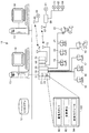
図1を参照すると、プロセス制御システム10は、データヒストリアン12に、そして1つ以上の、各々ディスプレイ画面14を有する、(いずれかのタイプのパーソナルコンピュータ、ワークステーション、等であってもよい)ホストワークステーションすなわちコンピュータ13に接続されたプロセスコントローラ11を含んでいる。コントローラ11は、入力/出力(I/O)カード26および28を介してフィールド装置15〜22にも接続されている。データヒストリアン12は、任意の所望のタイプのメモリおよびデータを格納するための任意の所望のまたは既知のソフトウェア、ハードウェアあるいはファームウェアを有するいずれかの所望のタイプのデータ収集ユニットであってもよい。データヒストリアン12は、図1に図解されているように、ワークステーション13から分離されていても、またはワークステーション13の1つの一部をなしていてもよい。例として、Fisher−Rosemount Systems, Inc.より販売されているDeltaVコントローラであってもよい、コントローラ11は、例えば、イーサネット(登録商標)接続または任意の他の所望の通信ネットワークを介してホストコンピュータ13におよびデータヒストリアン12に通信可能に接続されている。コントローラ11は、また、ここにさらに説明するように、結線接続かまたはワイアレスかの通信スキームのいずれかを用いてフィールド装置15〜22にも通信可能に接続されている。いずれのケースにおいても、いずれかの所望のハードウェア、ソフトウェアおよびファームウェアが、例えば、(結線接続の場合)標準4−20mA装置および/またはFOUNDATIONフィールドバスプロトコル、HARTプロトコル等の任意のスマート通信プロトコルと関連する場合がある、スキームを履行するために、利用されてもよい。図1に示される例示的な実施の形態において、しかしながら、コントローラ11とフィールド装置15〜22との間の通信は、結線接続を含んでいる。
Referring to FIG. 1, the
より一般的に、フィールド装置15〜22は、センサ、バルブ、送信機、ポジショナ等のいずれかのタイプの装置であってもよく、同時にI/Oカード26および28は、任意の所望の通信またはコントローラプロトコルに適合するいずれかのタイプのI/O装置であってもよい。図1に図解される実施の形態において、フィールド装置15〜18は、アナログラインを通じてI/Oカード26に通信する標準4−20mA装置であり、同時にフィールド装置19〜22は、フィールドバスプロトコル通信を用いてデジタルバスを通じてI/Oカード28に通信する、フィールドバスフィールド装置等の、スマート装置である。もちろん、フィールド装置15〜22は、将来において開発されるいずれかの標準またはプロトコルをも含む、任意の他の所望の標準またはプロトコルに適合させてもよい。
More generally, the field devices 15-22 may be any type of device such as sensors, valves, transmitters, positioners, etc., while the I /
コントローラ11は、メモリ24に格納された1つ以上の制御ルーチンあるいはそれについての任意のモジュール、ブロック、またはサブルーチンを履行または監督するプロセッサ23を含んでいる。メモリ24に格納されたプロセス制御ルーチンは、そこに格納された制御ループを含みまたはそれと関連していてもよい。一般的にいえば、コントローラ11は、いずれかの所望の態様においてもプロセスを制御すべく装置15〜22、ホストコンピュータ13およびデータヒストリアン12と通信する。ここに説明されているいずれかの制御ルーチンまたはモジュールも、所望の場合には、異なるコントローラまたは他の装置により履行されまたは実行されるそれらの役割を持っていてもよい。同様に、プロセス制御システム10内で履行されるべくここに説明された制御ルーチンまたはモジュールは、ソフトウェア、ファームウェア、ハードウェア等を含むいずれかの形態をとってもよい。この本発明の目的のために、制御モジュールは、任意のコンピュータ読み取り可能な媒体上に格納された、例えばルーチン、ブロックまたはそれらの任意のエレメントを含むプロセス制御システムの任意の部品または部分であってもよい。サブルーチン、(コードの行等の)サブルーチンの部分等の、制御プロシージャのモジュールまたは任意の部分である場合がある、制御ルーチンは、オブジェクト指向プログラミングを用い、ラダーロジック、シーケンシャルファンクションチャート、ファンクションブロックダイアグラムを用い、あるいは任意の他のソフトウェアプログラミング言語または設計パラダイムを用いるような、任意の所望のソフトウェアフォーマットにおいて履行されてもよい。同様に、制御ルーチンは、例えば1つ以上のEPROM、EEPROM、アプリケーション特定集積回路(ASIC)、または任意の他のハードウェアまたはファームウェアエレメント、にハードコードされていてもよい。またさらに、制御ルーチンは、グラフィカル設計ツールまたは任意の他のタイプのソフトウェア/ハードウェア/ファームウェアプログラミングまたは設計ツールを含む、任意の設計ツールを用いて設計されてもよい。それゆえ、コントローラ11は、任意の所望の態様での制御ストラテジまたは制御ルーチンを履行すべく形成されていてもよい。
The
いくつかの実施の形態において、コントローラ11は、一般に機能ブロックと称されるものを用いて、制御ストラテジまたはスキームを履行し、そこでは、各機能ブロックは、プロセス制御システム10内のプロセス制御ループを履行すべく(リンクと呼ばれる通信を介して)他の機能ブロックと共に動作する全体の制御ルーチンのオブジェクトまたは他の部分(例えばサブルーチン)である。機能ブロックは、典型的には、送信機、センサまたは他のプロセスパラメータ計測装置に関連するような、入力機能、PID、ファジー論理等の制御を行う制御ルーチンに関連するような、制御機能、または、プロセス制御システム10内の任意の物理的機能を行うために、バルブ等の、任意の装置の動作を制御する出力機能のうちの1つを果たす。もちろん、ハイブリッドおよび他のタイプの機能ブロックも存在し、ここに利用されてもよい。機能ブロックは、コントローラ11に格納され且つそれにより実行されてもよく、それは典型的には、機能ブロックが、標準4−20mA装置およびHART装置等のあるタイプのスマートフィールド装置のために、またはそれと関連して使用される場合のこととなる。代替的にまたは付加的に、機能ブロックは、フィールド装置それら自体に格納され且つそれらにより履行されてもよく、それは、フィールドバス装置を伴う場合であってもよい。制御システム10の説明は、機能ブロック制御ストラテジを用いてここに提供されているが、本発明の技術およびシステムは、また、ラダーロジック、シーケンシャルファンクションチャート等の、他の手法を用いて、あるいは、任意の他の所望のプログラミング言語またはパラダイムを用いて、履行されまたは設計されてもよい。
In some embodiments, the
図1の分解されたブロック30により図解されているように、コントローラ11は、ルーチン32および34として示された多数の単一ループ制御ルーチンを含んでいてもよく、そして、所望の場合は、制御ループ36として図解されているように、1つ以上の改良された制御ループを履行してもよい。そのようなループは各々、典型的には、制御モジュールと称されている。単一ループ制御ルーチン32および34は、それぞれ、適宜、アナログ入力(AI)およびアナログ出力(AO)機能ブロックに接続された、単一入力/単一出力ファジー論理制御ブロックおよび単一入力/単一出力PID制御ブロックを用いる単一ループ制御として図解されており、それはバルブ等のプロセス制御装置に、温度および圧力送信機等の計測装置に、あるいはプロセス制御システム10内における任意の他の装置に関連していてもよい。改良された制御ループ36は、1つ以上のAI機能ブロックに通信可能に接続された入力および1つ以上のAO機能ブロックに通信可能に接続された出力を有する改良された制御ブロック38を含むものとして図解されているが、改良された制御ブロック38の入力および出力は、他のタイプの入力を受けるべくそして他のタイプの制御出力を行うべく任意の他の所望の機能ブロックまたは制御エレメントに接続されていてもよい。改良された制御ブロック38は、いずれかのタイプの複数回の入力、複数回の出力制御スキームを履行してもよく、そしてモデル予測制御(MPC)ブロック、ニューラルネットワークモデル化または制御ブロック、多変量ファジー論理制御ブロック、リアルタイムオプティマイザブロック等を構成しまたは含んでいてもよい。改良された制御ブロック38を含む、図1に図解された機能ブロックは、コントローラ11により実行されてもよく、あるいは、代わりとして、ワークステーション13の1つまたはフィールド装置19〜22の1つ等の、いずれかの他の処理装置内に配置され且つそれにより実行されてもよいことが理解されるであろう。
As illustrated by the exploded
図2を参照すると、制御ループ32、34および36の各々の履行は、概して、制御ルーチンの複数回の繰り返し40を介して周期的な実行のために適合されている。従来のケースでは、各繰り返し40は、例えば、送信機または他のフィールド装置により提供される更新されたプロセス計測42によりサポートされる。計測値の制御への同期を制限しないようにするため、多くの過去のコントローラ(または制御ループ)は、2〜10倍量の計測をオーバサンプリングすべく設計されている。そのような助長されたオーバサンプリングは、プロセス計測が、制御スキームにおいて現在使用するためのものであることを保証する。また、制御変量を最小化するために、フィードバック制御仕様の既存の設計は、プロセス応答時間よりも4〜10倍高速で実行されなければならず、それは図2に、プロセス時定数+プロセス入力におけるステップ変化44の後のプロセス遅延として描出されている。より一般的には、プロセス応答は、プロセス出力における変化または時間についての変量46により示される。したがって、これらの既存の設計の要求を満足するため、計測値は、図2に図解されるように、しばしば、プロセスが応答するよりも非常に高速でサンプリングされる。
Referring to FIG. 2, the implementation of each of the
一般的にいえば、本発明の技術は、そのような高い速度で計測値を送信するという試みを指向したものである。例えば、上述のように、計測に関連する検知機能性は、センサまたは送信機のための電力供給の多くを消費することはないが、ワイアレス通信リンクを介した計測値の伝送は、長時間にわたって、膨大な電力を消耗する場合がある。たとえ、基礎フィールドバス制御スキームにおけるように、計測と制御実行が同期されていてさえも、プロセス応答よりも4〜10倍速いスケジュール制御への既存のアプローチは、依然としてデータ送信の間過大な電力消費を結果として生ずる場合がある。したがって、送信機の電力消費を低減するために、本発明の技術は、概してどの程度の頻度で計測値が通信されるかについて最小限にサポートする。 Generally speaking, the technique of the present invention is directed to an attempt to transmit measurement values at such a high speed. For example, as described above, the sensing functionality associated with the measurement does not consume much of the power supply for the sensor or transmitter, but the transmission of measurements over the wireless communication link takes a long time. , May consume enormous power. Even if measurement and control execution are synchronized, as in the basic fieldbus control scheme, existing approaches to schedule control that are 4-10 times faster than process response still consume excessive power during data transmission. As a result. Thus, to reduce transmitter power consumption, the techniques of the present invention generally support minimally how often measurements are communicated.
そのために、そして本発明の1つの態様に従って、本発明の技術は、概してプロセス制御システム10、そして、ある一定の条件が満足されたときに非周期的なベースで新規な計測値を送信すべく、コントローラ11ならびに送信およびそれの他のフィールド装置を形成している。1つの実施の形態において、新規な計測値は、予め設定されたしきい値(例えば、有意となるように決定された量)より多い量のプロセス変数が変化したか否かに基づいて送信される。より詳細には、もし、新規な計測値と最後に通信された計測値との間の差異が、特定された分解能よりも大きい場合は、計測が更新されるようにトリガが生成され得る。
To that end, and in accordance with one aspect of the present invention, the techniques of the present invention are generally directed to the
他の場合において、上述のケースにおけるように、差異が特定の分解能を超えるときに、それに加えて最後の通信からの時間が予め設定されたリフレッシュ時間を超えるときに、新規な計測値が送信される。言い換えれば、プロセス変数(例えば、制御実行繰り返し48と50の間のプロセス応答)における変化か、またはデフォルト時間(例えば、繰り返し52と54の間に経過した時間)の経過かのいずれかが、結果的に計測値の伝送を生じさせる。多かれ少なかれ頻繁な更新は、(例えば、プロセス時定数により、示されるように)プロセスがゆっくり動くかまたは応答が高速か否かに応じて適切である限りは、計測値伝送のための、リフレッシュ、またはデフォルトの時間は制御ループの間に変動してもよい。いくつかの場合において、時定数に基づく制御ループの調整の間に決定がなされ、その後に所望により調整される場合がある。いずれかの場合において、デフォルトまたはリフレッシュ時間は、計測更新を行わない時間が経過した後に、統合全性チェックまたは制御停止装置として作用する。そのようなチェックは、例えば、目標に対するプロセス変数の最終駆動を容易にするのに有用である場合がある。
In other cases, as in the case above, when the difference exceeds a certain resolution, a new measurement is sent when the time since the last communication exceeds a preset refresh time. The In other words, either a change in a process variable (eg, a process response between
それに対して、計測値を取得することについて応答可能な送信機、センサまたは他のフィールド装置は、現行のプロセス応答時間の4〜10倍等での、いずれかの所望の速度で計測値を、なお周期的にサンプリングしてもよい。本発明の技術は、次に、サンプリングされた値がコントローラ11へ送信されるか否かを決定する。
In contrast, a transmitter, sensor, or other field device that is responsive to taking measurements, takes measurements at any desired speed, such as 4-10 times the current process response time. The sampling may be performed periodically. The technique of the present invention then determines whether the sampled value is transmitted to the
図3は、本発明の技術が、コントローラ11および、より一般的に、図1のプロセス制御システム10の動作をサポートすべく、プロセス制御データのワイアレス通信の間における電力消費を低減するために適用される例示的な場合を描いている。しかし、図1および図3に示される結線接続は、本発明の技術の適用を利用、またそこから利益を得てもよいことに留意すべきである。例えば、1つ以上の結線接続装置が、また、限定された電力供給に依存していてもよく、またそうでない場合は、低減されたデータ伝送から利益を得てもよい。1つの例示的な場合において、システム10は、制御実行速度よりも遅い速度で計測データを提供すべく設計されたサンプルアナライザまたは他のサンプリングシステムを含んでいてもよい。
FIG. 3 illustrates that the technique of the present invention is applied to reduce power consumption during wireless communication of process control data to support operation of
図解における便宜のために、フィールド装置15〜22が、I/O装置26および28を介してコントローラ11に結線接続された状態で、多数のワイアレスフィールド装置がプロセス制御システム10に付加されていることにもさらに留意すべきである。代替的な実施の形態において、1つ以上のフィールド装置15〜22は、また、あるいは本発明の技術にしたがってワイアレスに選択的にコントローラ11と通信してもよい。
For convenience in the illustration, a number of wireless field devices have been added to the
図3に示される例示的なケースでは、しかしながら、本発明の技術は、概して、送信機60〜64により計測されまたは検知されたデータのワイアレス伝送を含んでいる。ワイアレス通信は、現在既知のまたは後に開発されるハードウェア、ソフトウェアまたはそれらの組合せを含むいずれかの所望の設備を用いて確立され得る。この実施の形態の例示的な設備は、送信機60に結合され且つそれに専用のアンテナ65と、送信機61〜64のための通信を集合的に取り扱うためのアンテナ67を有するワイアレスルータまたは他のモジュール66とにより象徴されている。いくつかの場合において、送信機60〜64は、プロセスセンサと制御室との間の単独のリンクを構成し、それ自体が、製品品質および流れに欠陥を生じさせないようにすべく制御ネットワークに対して正確な信号を送ることが確実なものとなり、これにより、しばしばプロセス変数送信機(PVT)と称される、送信機60〜64は、プロセス制御システム10における重要な役割を果たし得る。
In the exemplary case shown in FIG. 3, however, the techniques of the present invention generally include wireless transmission of data measured or sensed by transmitters 60-64. Wireless communication may be established using any desired equipment including currently known or later developed hardware, software, or combinations thereof. An exemplary installation of this embodiment is a wireless router or other device that has an
ワイアレス通信リンクの受信端において、コントローラ11は、それぞれのアンテナ72および74を備える1つ以上のI/O装置68および70を有していてもよい。より一般的には、本発明の技術の実施は、送信機またはワイアレス設備のいずれかの構成にも限定されるものではない。
At the receiving end of the wireless communication link, the
送信機60〜64または他のフィールド装置の各々は、1つ以上の制御ループまたはルーチンで使用するためにコントローラ11に対してそれぞれのプロセス変数(例えば、流れ、圧力、温度またはレベル)を示すプロセス信号を送る。一般的には、コントローラ11は、ワイアレス通信および、特に、プロセス信号の、受信、をサポートすべく指向された多数のエレメントを含んでいてもよい。エレメントは、例えば、メモリ24に格納されるソフトウェアルーチンあるいはコントローラ11における他のいずれかの箇所に存在するハードウェアまたはファームウェアを、含みまたは構成してもよい。いずれかの場合において、ワイアレス通信が受信される態様(例えば、復調、デコード等)は、いずれか所望の形態をとってもよく、そして一般的には、ここに述べたもとなるであろう。1つの例において、コントローラ11は、到来信号を処理するために通信スタック80と、そして到来信号が計測更新を提供したときを検出すべくモジュールまたはルーチン82を含んでいてもよい。検出ルーチン82は、次に、通信スタック80を介して提供されるデータが新規な計測値または計測更新を含んでいることをあらわすべくフラグまたは他の信号を生成してもよい。新規なデータおよび更新フラグは、次に、図1に概略的に示されたルーチンに関連して上述したように履行されるべく1つ以上の制御モジュール84に提供されてもよく、そして、以下においてさらに詳細に述べられる。
Each of the transmitters 60-64 or other field devices is a process that indicates a respective process variable (eg, flow, pressure, temperature or level) to the
いくつかの場合において、通信スタック80および更新検出モジュール82は、1つ以上のI/O装置26、28、68および70(図1および図3)により履行される。さらに、更新検出モジュール82がその決定をなす態様は、ハードウェア、ソフトウェア、ファームウェアまたはそれらの任意の組合せを含んでいてもよく、そしてプロセス変数の値を比較するための任意の適切なルーチンを含んでいてもよい。
In some cases,
ワイアレス(または他の)送信機について上述の通信技術は、概して、非周期的な、不規則なまたそうでない場合はより頻度の低いデータ伝送を結果として生じる。しかしながら、コントローラ11へのフィールドからの計測値の通信は、伝統的に、制御ルーチンの周期的な実行を順次サポートすべく、周期的な態様で報告すべく構成されている。換言すれば、制御ルーチンは概して計測値の周期的な更新のために、そしてそれを前提に設計されている。
The communication techniques described above for wireless (or other) transmitters generally result in aperiodic, irregular and otherwise less frequent data transmissions. However, the communication of measured values from the field to the
非周期的な計測値の更新に適応させるために、本発明の他の態様は、概して、制御ルーチンを変更しまたは再構築すべく指向されている。この態様において、プロセス制御システム10は、制御実行周期よりも、一層低い頻度で生起する非周期的または他の更新を前提としている。そして、結果として、本発明の技術は、プロセス制御ルーチンの周期的な実行にもかかわらず、プロセス変数計測についての除外報告の形態をサポートしている。
To accommodate non-periodic measurement updates, other aspects of the present invention are generally directed to changing or reconfiguring the control routine. In this aspect, the
実際に、(例えば、z変換、差分方程式を用いる)制御設計における基礎をなす仮定および、比例−積分−微分(PID)制御等の、制御ルーチンのデジタル履行は、アルゴリズムが周期的なベースで実行されることである。もし、計測が更新されなければ、そのときは、積分(またはリセット)部分等のステップあるいはルーチンの寄与が適切でない場合がある。例えば、もし、制御アルゴリズムが、期限を失効した計測値を用いて実行すべく、継続される場合、出力はリセット調整および最後の計測値と設定値との間の誤差に基づいて動くべく継続するであろう。他方で、もし、制御ルーチンが新規な計測が通信されたときにのみ実行される場合は、設定値に対する制御応答が変化し且つ計測された障害に対するフィードフォワード作用が遅延され得る。制御ルーチンは、最後の繰り返しからの経過時間に基づく計算をも含んでいてもよい。しかし、非周期的なおよび/またはより低い頻度の計測の伝送により、制御実行周期(すなわち、最後の繰り返しからの時間)に基づくリセット寄与の計算は、結果としてプロセスの変動を増大させる。 In fact, digital implementation of control routines, such as underlying assumptions in control design (eg, using z-transform, differential equations) and proportional-integral-derivative (PID) control, are performed on an algorithmic periodic basis. It is to be done. If the measurement is not updated, then the step or routine contributions such as the integral (or reset) portion may not be appropriate. For example, if the control algorithm is continued to run with an expired measurement, the output will continue to move based on the reset adjustment and the error between the last measurement and the setpoint. Will. On the other hand, if the control routine is executed only when a new measurement is communicated, the control response to the setpoint changes and the feedforward action for the measured fault can be delayed. The control routine may also include calculations based on the elapsed time since the last iteration. However, due to the transmission of non-periodic and / or less frequent measurements, calculation of the reset contribution based on the control execution period (ie, time since the last iteration) results in increased process variability.
前述の挑戦を考慮して、そして計測値が周期的なベースで更新されないときに正確且つ応答性のよい制御を提供するために、ここに開示されているのは、概してプロセス変数の更新が有効か否かに基づいてプロセス制御ルーチンを変更する制御技術である。いくつかの場合において、制御ルーチンは、最後の計測更新から予測されるプロセス応答に基づいて本発明の技術に従って再構築されてもよい。 In view of the aforementioned challenges and to provide accurate and responsive control when measurements are not updated on a periodic basis, it is generally disclosed that process variable updates are effective. This is a control technique for changing the process control routine based on whether or not. In some cases, the control routine may be reconstructed according to the techniques of the present invention based on the process response predicted from the last measurement update.
本発明の技術の1つの態様に従って形成された制御スキームの例示的な実施の形態は、図4に示されており、そこでは、プロセスが、一般的に且つ概略的に100にて示されている。例示的な制御スキームは、図3に関連しても示され且つ述べられている通信スタック80、更新検出モジュール82および制御モジュール84の機能性を提供すべく形成されているコントローラ11のコンポーネント(または、所望により、コンポーネントのセット)102に対応していてもよい。一般的にいえば、コントローラ11は、例えば、ワークステーション13(図1)の1つから、またはプロセス制御システム10内のまたはそれと通信する任意の他の発生源から、1つ以上のプロセス入力または他の制御信号を発生すべく設定値を受信してプロセス100を制御し、104にて概略的に示されている計測されたまたは計測されていない障害を受ける場合がある。上述のように、プロセス入力信号(群)は、プロセスの動作における応答をもたらすべくバルブまたは他の任意のフィールド装置に関連するアクチュエータを制御してもよい。プロセス入力信号における変化に応答するプロセスは、送信機、センサまたは他のフィールド装置106により計測あるいは検知され、それは、例えば、図3に示される送信機60〜64のいずれか1つに対応してもよい。結果として、送信機106とコントローラ11との間の通信リンク(鎖線を介して描かれている)は、ワイアレス接続を含んでいてもよい。代替的に、または付加的に、通信は、所望により、結線接続を含んでいてもよく、それは、例えば、間欠的に有効または動作状態となることで、本発明の技術から利益を得る場合がある。
An exemplary embodiment of a control scheme formed in accordance with one aspect of the present technique is shown in FIG. 4, where the process is shown generally and schematically at 100. Yes. An exemplary control scheme is a component of controller 11 (or configured to provide the functionality of
この例示的なケースでは、コントローラ11が、PI制御ルーチン等の、単一の閉ループ制御ルーチンを履行する。したがって、制御ループは、設定値をプロセス変数データと比較するための合計点108、比例ゲインエレメント110、例えば、比例および積分寄与を組合せるための他の合計点112、および高−低リミッタ114を含む、いくつかの標準PIプロトコルスキームエレメントを含んでいる。制御スキームの標準エレメントに加えて、本発明の制御技術のこの実施の形態は、制御信号に対する予測されるプロセス応答を示唆すべく修正されたフィルタ116を用いている。この例示的なケースにおいて、予測されるプロセス応答は、最初に見積もられ、その後PI制御スキームの積分寄与を決定するポジティブフィードバックループに含められる修正されたフィルタにより実現される。より一般的に、制御履行に利用される予測されるプロセス応答は、プロセスの任意のモデルによりもたらされ、そしてポジティブフィードバックループ、フィルタまたは積分またはリセット寄与における組み込みに限定されることはない。例えば、予測されるプロセス応答を与えるモデルを利用する制御は、制御ルーチンがPID制御スキームを履行するように微分寄与を組み込んでいてもよい。
In this exemplary case, the
修正されたフィルタ116は、多くの方法における伝統的なリセットまたは積分寄与とは相違している。背景として、伝統的なPIコントローラは、リセット寄与を決定するためにポジティブフィードバックネットワークを用いて履行される場合がある。数学的には、伝統的な履行のための伝達関数が拘束を受けていない制御、すなわち無制限出力、についての標準公式と等価であることが示され得る。
O(s)/E(s) = KP{1+(1/sTReset)}
ここで、KP=比例ゲイン
TReset=リセット、秒である。
ポジティブフィードバックネットワークの1つの利点は、コントローラ出力が、すなわち、リミッタ114により、高くまたは低く制限されているとき、リセット寄与は、ワインディングアップ(winding up)が自動的に防止されることである。
The modified
O (s) / E (s) = K P {1+ (1 / sT Reset )}
Where K P = proportional gain
T Reset = Reset, seconds.
One advantage of a positive feedback network is that when the controller output is limited to high or low by the
本発明の1つの態様によれば、本発明のシステムおよび方法により履行される制御技術は、プロセス変数の非周期的な計測更新を用いることを含んでいる。リセット寄与のポジティブフィードバックネットワーク(または他のフィルタまたはルーチン)は、そのような更新に適応させるべく修正される。特に、フィルタ116(または他のルーチン)は、最後に計算されたフィルタ出力が新規な計測値が通信される(例えば、受信される)まで維持される。新規な計測値が受信されたとき、フィルタ116は、最後のコントローラ出力(すなわち、制御信号)および新規な計測値が通信されてからの経過時間に基づいて、新規なフィルタ出力を計算する。この制御技術の例示的なケースは、以下に述べられる。
FN=FN-1+(ON-1−FN-1)*{1−e(−ΔT/TReset)}
ここで、FN=新規のフィルタ出力
FN-1=最後のフィルタ出力の実行
=最後の新規計測後のフィルタ出力
ON-1=最後の制御出力の実行
ΔT=新規の値が通信されてからの経過時間
このようにして、制御ルーチンは、新規な計測に基づいて制御入力を計算するとき、最後の計測値伝送に対する予測されるプロセス応答を算入する。そして、結果として、送信機は、上述の技術等の、制御実行の繰り返し毎に更新が提供されない任意の通信技術が履行される場合がある。ワイアレス伝送を含むそれらの通信技術のために、このことは、ワイアレス送信機および他の装置が、プロセス制御のためのデータ伝送の結果として消費電力量を最小限に抑えることが可能になる。
According to one aspect of the present invention, the control technique implemented by the system and method of the present invention includes using non-periodic measurement updates of process variables. The positive feedback network (or other filter or routine) of the reset contribution is modified to accommodate such updates. In particular, the filter 116 (or other routine) is maintained until the last calculated filter output is communicated (eg, received) a new measurement. When a new measurement is received, the
F N = F N−1 + (O N−1 −F N−1 ) * {1−e (−ΔT / T Reset )}
Where F N = new filter output
F N-1 = Execute the last filter output
= Filter output after the last new measurement
O N-1 = Execution of the last control output
ΔT = Elapsed time since new value was communicated In this way, the control routine takes into account the expected process response for the last measured value transmission when calculating the control input based on the new measurement. And as a result, the transmitter may implement any communication technology that does not provide an update for each iteration of control execution, such as the technology described above. For those communication technologies involving wireless transmission, this allows wireless transmitters and other devices to minimize power consumption as a result of data transmission for process control.
上述のような閉ループ制御ルーチンのリセット寄与は、プロセスが定常状態の動作を示す場合のように、多くの方法におけるプロセス応答の正確な表現を提供し得ることに留意すべきである。デッドタイム(待ち時間)支配プロセス等の、他のプロセスは、以下に論じられるように、予測されるプロセス応答をモデル化するルーチンにおける付加的なコンポーネントの組み込みを含んでいてもよい。しかしながら、一次モデルにより十分に表現されているプロセスに関して、プロセス時定数は、PI(またはPID)コントローラについてのリセット時間を決定するために使用されてもよい。より詳細には、もし、プロセス時定数に等しくリセット時間を設定する場合、リセット寄与は、その時間全体にわたってルーチンが予測されるプロセス応答を反映するように、概して比例寄与をキャンセルする。このアプローチは、図4の例示的な実施の形態に反映されており、そこでは、プロセス時定数と同じ時定数を有するフィルタを持つポジティブフィードバックネットワークによりリセット寄与が有効となる。他のモデルが利用される間、ポジティブフィードバックネットワーク、フィルタ、またはモデルが、既知のまたは見積もられたプロセス時定数を有するプロセスの予測される応答を決定するための便利な機構を提供する。 It should be noted that the reset contribution of the closed loop control routine as described above can provide an accurate representation of the process response in many ways, such as when the process exhibits steady state operation. Other processes, such as dead time dominating processes, may include the incorporation of additional components in routines that model the expected process response, as discussed below. However, for processes that are well represented by the first order model, the process time constant may be used to determine the reset time for the PI (or PID) controller. More specifically, if a reset time is set equal to the process time constant, the reset contribution generally cancels the proportional contribution so that the routine reflects the expected process response over that time. This approach is reflected in the exemplary embodiment of FIG. 4, where the reset contribution is enabled by a positive feedback network with a filter having the same time constant as the process time constant. While other models are utilized, a positive feedback network, filter, or model provides a convenient mechanism for determining the predicted response of a process having a known or estimated process time constant.
例として、ワイアレス通信のための規則が守られたとき、本発明の技術を含む試験の期間での多くの通信が、96%を超える量だけ低減される。制御性能における非周期的な計測更新の影響も、また、上述の修正されたPIアルゴリズムの使用を通して最小化される。特に、制御性能における差異は、以下において、周期的計測更新と非周期的更新との積分絶対誤差(IAE)の比較における表1に示されている。 As an example, when the rules for wireless communications are observed, many communications during the test period involving the technology of the present invention are reduced by more than 96%. The impact of non-periodic measurement updates on control performance is also minimized through the use of the modified PI algorithm described above. In particular, differences in control performance are shown below in Table 1 in the comparison of integral absolute error (IAE) between periodic measurement updates and aperiodic updates.

PID制御を必要とするプロセスのために、PID出力への速度寄与は、また、新規な計測値が受信されたときにのみ再計算され且つ更新される場合がある。それらの場合において、導関数計算は、最後の新規な計測からの経過時間を同様に使用してもよい。 For processes that require PID control, the velocity contribution to the PID output may also be recalculated and updated only when a new measurement is received. In those cases, the derivative calculation may use the elapsed time since the last new measurement as well.
図4に示されるように、通信スタック80および、いくつかの実施の形態における、更新検出モジュール82(図3)は、修正されたフィルタ116のための新規値フラグを生成すべく送信機106からの到来データを処理する。新規値フラグは、新規なフィルタ出力が計算されるべきときを決定すべく修正されたフィルタ116に供給される。
As shown in FIG. 4, the
図5を参照すると、本発明の制御技術に従って形成された代替的なコントローラ120は、図4に示されるコントローラ11に対して多くの点で類似している。結果として、両方のコントローラに共通なエレメントは、類似の参照数字にて識別される。コントローラ120は、しかしながら、計測値送信の間の予測されるプロセス応答を決定するルーチン内に付加的なエレメントを組み込んでいる。この場合において、プロセスは、相当量のデッドタイムを有しているものとして特徴付けられそして、結果として、ユニットまたはブロック122は、デッドタイム補償のためのモデル内に含められる。デッドタイムユニット122の組み込みは、概して、プロセス応答のより正確な表現に到達するのを助ける。より詳細には、デッドタイムユニット122は、いずれかの所望の様式においても履行されてよく、そしてスミスプレディクタまたは他の既知の制御ルーチンと共通の方法を含みまたは利用してもよい。
Referring to FIG. 5, the
上述の実施の形態により示されているように、制御信号に対する予測プロセス応答を決定するために応答可能なフィードバック、フィルタまたは他のルーチンは、プロセス制御ルーチンの残部からいずれかのオフセットまたは他のエラーをも除去するのを助けるいずれかのタイプのモデル、ネットワークまたは他の構成のプロセス制御エレメントを含んでいてもよい。このようにして、本発明の技術は、種々の異なるプロセスについて十分適合し、そして一次動作を示すものに限定されることはない。それと全く反対に、本発明の技術は、異なるモデル、フィルタまたはブロックが、予測されるプロセス応答を決定するのに含まれる状況に適用可能であり、そして、プロセスモデルが、高度に正確な状況における使用に限定される必要はない。 As shown by the above embodiments, feedback, filters or other routines that can be responsive to determine the predicted process response to the control signal are either offset or other errors from the rest of the process control routine. May include any type of model, network, or other configuration of process control elements that help remove the In this way, the techniques of the present invention are not limited to those that are well suited for a variety of different processes and that exhibit primary operation. In contrast, the techniques of the present invention are applicable to situations where different models, filters or blocks are involved in determining the predicted process response, and the process model is in a highly accurate situation. It need not be limited to use.
上述のように、本発明の技術は、プロセス変数をオーバサンプリングするための必要性を回避するプロセス制御形態をサポートし、それにより、ワイアレス通信および計測値が定期的にまたは制御実行周期と同じくらいの頻度で有効でない場合がある他の送信機シナリオの使用を容易にする。手短に言えば、本発明の技術は、プロセス制御ルーチン実行のための計測データを定期的に送信しなければならないことを回避する。送信機(または他のフィールド装置)の設計における本発明の変化および制御修正の結果として、計測値は、概して最後の通信された値からの有意な変化またはリフレッシュ時間の後、にのみ通信すべく送信される。その結果として、送信機通信の頻度およびデータ送信のために使用される電力の量の両方が、有意に低下する。 As mentioned above, the technique of the present invention supports a process control configuration that avoids the need to oversample process variables, so that wireless communication and measurements are as regular or as long as the control execution period. Facilitates the use of other transmitter scenarios that may not be effective at a certain frequency. In short, the technique of the present invention avoids having to periodically send measurement data for process control routine execution. As a result of the changes and control modifications of the present invention in the design of the transmitter (or other field device), measurements should generally only be communicated after a significant change from the last communicated value or refresh time. Sent. As a result, both the frequency of transmitter communications and the amount of power used for data transmission is significantly reduced.
本発明の方法、システムおよび技術の実施は、いずれの1つの特別なワイアレスアーキテクチャまたは通信プロトコルに限定されることはない。適切な例示的アーキテクチャおよび通信サポートスキームは、「プロセス制御システムのためのワイアレスアーキテクチャとサポート(Wireless Architecture and Support for Process Control Systems)」と題されて、2005年6月17日に出願された米国特許出願第11/156,215号に説明されており、その全開示は引用によりここに組み込まれている。実際、制御ルーチンに対する本発明の修正は、制御ルーチンが周期的様式で履行されるいずれかの状況についてもよく適合させるが、制御繰り返し毎のプロセス変数計測の更新はない。他の例示的状況は、例えば、アナライザにより、または実験サンプルを介してサンプル値が不規則にまたはよりまれに供給される。
The implementation of the method, system and technique of the present invention is not limited to any one special wireless architecture or communication protocol. A suitable exemplary architecture and communication support scheme is a U.S. patent filed June 17, 2005 entitled "Wireless Architecture and Support for Process Control Systems".
本発明の技術の実施は、単一入力、単一出力のPIまたはPID制御ルーチンを使用することに限定されるものではないが、むしろ多数の異なる複数回入力および/または複数回出力制御スキームおよび縦続接続された制御スキームに適用される場合がある。より一般的には、本発明の技術は、モデル予測制御(MPC)のように、1つ以上のプロセス変数、1つ以上のプロセス入力または他の制御信号を含むいずれかの閉ループモデルベースの制御ルーチンにも適用されてよい。 Implementation of the techniques of the present invention is not limited to using a single input, single output PI or PID control routine, but rather a number of different multi-input and / or multi-output control schemes and May apply to cascaded control schemes. More generally, the techniques of the present invention provide any closed-loop model-based control that includes one or more process variables, one or more process inputs, or other control signals, such as model predictive control (MPC). It may also apply to routines.
「フィールド装置」なる用語は、ここでは、多数の装置または装置の組合せ(すなわち、送信機/アクチュエータのハイブリッド等の多種多様な機能を提供する装置)、加えて、制御システムにおける機能を果たすいずれかの他の装置をも含む、広い意味に用いられている。いずれにせよ、フィールド装置は、例えば入力装置(例えば、温度、圧力、流速、等のプロセス制御パラメータを示す状態、計測値または他の信号を提供するセンサおよび器具等の装置)、ならびにコントローラおよび/または他のフィールド装置から受信されるコマンドに応答して作用する制御演算子またはアクチュエータを含んでいてもよい。 The term “field device” herein refers to any device or combination of devices (ie, a device that provides a wide variety of functions, such as a transmitter / actuator hybrid), as well as any that performs a function in a control system. It is used in a broad sense, including other devices. In any case, the field device may be, for example, an input device (eg, a device that provides a process control parameter such as temperature, pressure, flow rate, etc., a device that provides a measured value or other signal, such as sensors and instruments), and Alternatively, it may include a control operator or actuator that acts in response to commands received from other field devices.
履行されるとき、ここに説明されたソフトウェアのいずれかが、磁気ディスク、レーザディスク、他の記憶媒体上、コンピュータまたはプロセッサ等のRAMまたはROM内等のいずれかのコンピュータ読み取り可能なメモリに格納されていてもよい。同様に、このソフトウェアは、例えばコンピュータ読み取り可能なディスクまたは他の運搬可能なコンピュータ記憶機構または電話線、インターネット、ワールドワイドウェブ、いずれかの他のローカルエリアネットワークまたはワイドエリアネットワーク等、を含むいずれかの既知のまたは所望の配達方法を用いて、ユーザ、プロセスプラントまたはオペレータワークステーションに配達されてもよい(配達は、運搬可能な記憶媒体を介してそのようなソフトウェアを提供することと同様であるようにあるいは交換可能に考察され得る)。そのうえ、このソフトウェアは、変調または暗号化なしに直接的に提供されてもよく、あるいは、通信チャンネル上に送信される前に任意の適切な変調キャリア波および/または暗号化技術を用いて変調されおよび/または暗号化されてもよい。 When implemented, any of the software described herein is stored on a magnetic disk, laser disk, other storage medium, in any computer-readable memory, such as in a RAM or ROM such as a computer or processor. It may be. Similarly, the software may include, for example, a computer readable disk or other transportable computer storage or telephone line, the Internet, the World Wide Web, any other local area network or wide area network, etc. May be delivered to a user, process plant or operator workstation using known or desired delivery methods (delivery is similar to providing such software via a transportable storage medium) Or can be considered interchangeable). Moreover, the software may be provided directly without modulation or encryption, or may be modulated using any suitable modulated carrier wave and / or encryption technique before being transmitted over the communication channel. And / or may be encrypted.
本発明は、特定の例に関連して説明されてきたが、それは単に例示的なものであり、本発明を制限するものとはならないことが意図されており、本発明の実施の形態に対して、本発明の精神および視野から逸脱することなく、変化、付加または削除が、なされ得ることは、当業者において明白であろう。 Although the present invention has been described with reference to particular examples, it is intended to be illustrative only and is not intended to limit the invention. It will be apparent to those skilled in the art that changes, additions, or deletions can be made without departing from the spirit and scope of the invention.
Claims (16)
プロセッサと、
前記プロセスを制御するための制御信号を生成するための前記プロセス信号に応答すると共に前記プロセッサによる周期的な実行のための制御モジュールと、を含み、
前記プロセス信号は、前記プロセス変数の値の非周期的な更新を有し、
前記制御モジュールは、
周期的な実行を繰り返している間、前記プロセス変数の値の新たな更新が取得された場合に前記プロセス変数の値の前回の更新から前記プロセス変数の値の新たな更新までの経過時間を決定するために実行し、前記プロセス変数の値の前記前回の更新に対応して生成された前回の制御信号に対するプロセス応答の表現を生成するために実行するルーチンを有し、当該ルーチンは、前記前回の制御信号と前記プロセス変数の値の前回の更新から前記プロセス変数の値の新たな更新までの経過時間とを使用して前記前回の制御信号に対する前記プロセス応答の表現を生成するように構成され、かつ前記前回の制御信号に対する前記プロセス応答の表現を使用して前記制御信号を生成し、
前記ルーチンは、更に、前記プロセス変数の値の更なる更新が取得されなかったときに前記制御モジュールの周期的な実行が1回行われるか、または2回以上繰り返されるまで前記前回の制御信号に対する前記プロセス応答の表現を維持するように構成されているコントローラ。 A controller for use in controlling the process based on a process signal indicating a value of a process variable of the process,
A processor;
Anda control module for periodic execution by the processor as well as responsive to the process signal for generating a control signal for controlling the process,
The process signal has an aperiodic update of the value of the process variable;
The control module is
Determines the elapsed time from the previous update of the process variable value to the new update of the process variable value when a new update of the process variable value is acquired while repeating periodic execution A routine executed to generate a representation of a process response to a previous control signal generated in response to the previous update of the value of the process variable, the routine comprising: And generating a representation of the process response to the previous control signal using a control signal and an elapsed time from a previous update of the value of the process variable to a new update of the value of the process variable. And generating the control signal using a representation of the process response to the previous control signal ,
The routine further provides for the previous control signal until a periodic execution of the control module is performed once or repeated more than once when no further update of the value of the process variable is obtained . A controller configured to maintain a representation of the process response.
前記プロセス変数に基づいて前記プロセスのための制御信号を生成するステップと、
前記プロセス変数の値の新たな更新が有効であるか否かを検出し、前記プロセス変数の値の新たな更新が有効である場合に、前記プロセス変数の値の最後の更新からの経過時間を決定するステップと、を有し、
前記制御信号を生成するステップは、
前記前回の制御信号及び前記経過期間を使用して前記プロセス変数の値の最後の更新に応答して生成された前回の制御信号に対するプロセス応答の表現を生成するステップを有し、
前記制御信号は、前記プロセス変数の値の新たな更新及び前記前回の制御信号に対する前記プロセス応答の表現に基づいており、
前記プロセス変数の値の更なる更新が有効であると検出されるまで、前記制御信号の生成が1回行われるか、または2回以上繰り返されるまで前記前回の制御信号に対する前記プロセス応答の表現を維持するステップを有するプロセス制御方法。 A process control method for controlling a process having a process variable, comprising:
Generating a control signal for the process based on the process variable;
New updated value of the process variable to detect whether a valid, if a new update of the value of the process variable is valid, the time elapsed since the last update of the value of the process variable Determining, and
Generating the control signal comprises:
Generating a representation of a process response to a previous control signal generated in response to a last update of the value of the process variable using the previous control signal and the elapsed period;
The control signal is based on a new update of the value of the process variable and a representation of the process response to the previous control signal ;
A representation of the process response to the previous control signal until the generation of the control signal is performed once or is repeated two or more times until a further update of the value of the process variable is detected to be valid. A process control method comprising the step of maintaining.
コンピュータ読取可能な媒体と、
プロセッサによって実行されるために前記コンピュータ読取可能な媒体に格納された制御モジュールルーチンであり、前記プロセスを制御するための制御信号を生成させるための前記プロセス変数の値の更新に応じて実行される前記制御モジュールルーチンと、を具備し、
前記制御モジュールルーチンは、
前記プロセス変数の値の新たに受け入れられた更新の受信に応じて、前記プロセス変数の値の最後の更新から前記プロセス変数の値の新たに受け入れられた更新までの経過時間を決定するために実行する第1のルーチンと、
前記プロセス変数の値の最後の更新に応じて生成された前回の制御信号に対する前記プロセス応答の表現を生成するために実行する第2のルーチンであって、当該第2のルーチンは、前記前回の制御信号と前記プロセス変数の値の最後の更新から前記プロセス変数の値の新たに受け入れられた更新までの前記経過時間とを用いて前記前回の制御信号に対するプロセス応答の表現を生成するために実行し、当該第2のルーチンは、前記制御モジュールルーチンの最後の実行サイクルから前記プロセス変数の値の更なる更新が受け入れられないときに前記前回の制御信号に対するプロセス応答の表現を維持する、当該第2のルーチンと、
前記制御信号を生成するための前記プロセス変数の設定値及び前記プロセス変数の値の新たに受け入れられた更新値によって決定されたエラー要素と前記前回の制御信号に対する前記プロセス応答の表現を組み合わせるために実行する第3のルーチンと、を含む
プロセス制御システム。 A process control system for use in controlling the process based on receipt of an aperiodic update of a process variable value of the process,
A computer-readable medium;
A control module routine stored on the computer readable medium for execution by a processor, executed in response to an update of the value of the process variable to generate a control signal for controlling the process The control module routine,
The control module routine is
In response to receiving a newly accepted update of the value of the process variable, to determine an elapsed time from a last update of the value of the process variable to a newly accepted update of the value of the process variable A first routine to:
A second routine executed to generate a representation of the process response to a previous control signal generated in response to a last update of the value of the process variable, the second routine comprising: Run to generate a representation of the process response to the previous control signal using the control signal and the elapsed time from the last update of the value of the process variable to a newly accepted update of the value of the process variable And the second routine maintains a representation of the process response to the previous control signal when no further update of the value of the process variable is accepted from the last execution cycle of the control module routine. Two routines;
In order to combine an expression of the process response to the previous control signal with an error factor determined by a set value of the process variable for generating the control signal and a newly accepted update value of the value of the process variable including a third routine to be executed, the
Process control system.
Applications Claiming Priority (2)
| Application Number | Priority Date | Filing Date | Title |
|---|---|---|---|
| US11/258676 | 2005-10-25 | ||
| US11/258,676 US7587252B2 (en) | 2005-10-25 | 2005-10-25 | Non-periodic control communications in wireless and other process control systems |
Related Child Applications (1)
| Application Number | Title | Priority Date | Filing Date |
|---|---|---|---|
| JP2009244331A Division JP5308306B2 (en) | 2005-10-25 | 2009-10-23 | Process control system and process control method |
Publications (3)
| Publication Number | Publication Date |
|---|---|
| JP2007122726A JP2007122726A (en) | 2007-05-17 |
| JP2007122726A5 JP2007122726A5 (en) | 2009-12-10 |
| JP5207614B2 true JP5207614B2 (en) | 2013-06-12 |
Family
ID=37491528
Family Applications (2)
| Application Number | Title | Priority Date | Filing Date |
|---|---|---|---|
| JP2006289675A Active JP5207614B2 (en) | 2005-10-25 | 2006-10-25 | Controller, process control method and process control system |
| JP2009244331A Active JP5308306B2 (en) | 2005-10-25 | 2009-10-23 | Process control system and process control method |
Family Applications After (1)
| Application Number | Title | Priority Date | Filing Date |
|---|---|---|---|
| JP2009244331A Active JP5308306B2 (en) | 2005-10-25 | 2009-10-23 | Process control system and process control method |
Country Status (6)
| Country | Link |
|---|---|
| US (2) | US7587252B2 (en) |
| JP (2) | JP5207614B2 (en) |
| CN (3) | CN101963809B (en) |
| DE (1) | DE102006049832A1 (en) |
| GB (2) | GB2431752B (en) |
| HK (2) | HK1106590A1 (en) |
Families Citing this family (37)
| Publication number | Priority date | Publication date | Assignee | Title |
|---|---|---|---|---|
| US7587252B2 (en) | 2005-10-25 | 2009-09-08 | Fisher-Rosemount Systems, Inc. | Non-periodic control communications in wireless and other process control systems |
| US8719327B2 (en) * | 2005-10-25 | 2014-05-06 | Fisher-Rosemount Systems, Inc. | Wireless communication of process measurements |
| US7620460B2 (en) * | 2005-10-25 | 2009-11-17 | Fisher-Rosemount Systems, Inc. | Process control with unreliable communications |
| US7949417B2 (en) | 2006-09-22 | 2011-05-24 | Exxonmobil Research And Engineering Company | Model predictive controller solution analysis process |
| JPWO2010021027A1 (en) * | 2008-08-19 | 2012-01-26 | 株式会社松島機械研究所 | Level measurement system |
| US8428828B2 (en) * | 2009-03-05 | 2013-04-23 | GM Global Technology Operations LLC | Adaptive control system for automated vehicle applications |
| US9131004B2 (en) * | 2009-04-26 | 2015-09-08 | Jeffrey Alan Carley | Method and apparatus for network address resolution |
| US8405871B2 (en) * | 2009-09-10 | 2013-03-26 | Bentley Systems, Incorporated | Augmented reality dynamic plots techniques for producing and interacting in Augmented Reality with paper plots for which accompanying metadata is accessible |
| US20110276150A1 (en) * | 2010-05-10 | 2011-11-10 | Al-Duwaish Hussain N | Neural network optimizing sliding mode controller |
| US9217565B2 (en) | 2010-08-16 | 2015-12-22 | Emerson Process Management Power & Water Solutions, Inc. | Dynamic matrix control of steam temperature with prevention of saturated steam entry into superheater |
| US9335042B2 (en) | 2010-08-16 | 2016-05-10 | Emerson Process Management Power & Water Solutions, Inc. | Steam temperature control using dynamic matrix control |
| US9447963B2 (en) | 2010-08-16 | 2016-09-20 | Emerson Process Management Power & Water Solutions, Inc. | Dynamic tuning of dynamic matrix control of steam temperature |
| JP6031735B2 (en) * | 2011-06-13 | 2016-11-24 | ソニー株式会社 | Information processing apparatus, information processing method, and computer program |
| DE102011105375A1 (en) * | 2011-06-22 | 2012-12-27 | Abb Ag | Method for operating automation device, involves deriving period at which sample of field device is sent, from control deviation of control circuit |
| WO2013007867A1 (en) | 2011-07-11 | 2013-01-17 | Metso Automation Oy | Wireless control for process automation |
| EP2573631B1 (en) * | 2011-09-23 | 2015-10-21 | Honeywell spol s.r.o. | Controller that estimates delayed manipulated variables |
| US8788069B2 (en) * | 2011-09-27 | 2014-07-22 | Fisher-Rosemount Systems, Inc. | Method and apparatus for eliminating aliasing |
| US9163828B2 (en) | 2011-10-31 | 2015-10-20 | Emerson Process Management Power & Water Solutions, Inc. | Model-based load demand control |
| US11199824B2 (en) | 2012-01-17 | 2021-12-14 | Fisher-Rosemount Systems, Inc. | Reducing controller updates in a control loop |
| US9298176B2 (en) | 2012-01-17 | 2016-03-29 | Fisher-Rosemount Systems, Inc. | Compensating for setpoint changes in a non-periodically updated controller |
| US10423127B2 (en) | 2012-01-17 | 2019-09-24 | Fisher-Rosemount Systems, Inc. | Velocity based control in a non-periodically updated controller |
| JP5565431B2 (en) * | 2012-04-18 | 2014-08-06 | 横河電機株式会社 | Control device and control system |
| WO2014117371A1 (en) * | 2013-01-31 | 2014-08-07 | 西门子公司 | Process control method, device, and system |
| US9436174B2 (en) * | 2013-03-01 | 2016-09-06 | Fisher-Rosemount Systems, Inc. | Kalman filters in process control systems |
| US9405286B2 (en) * | 2013-03-01 | 2016-08-02 | Fisher-Rosemount Systems, Inc. | Use of predictors in process control systems with wireless or intermittent process measurements |
| CN106133624B (en) | 2014-03-20 | 2020-06-16 | 费希尔-罗斯蒙特系统公司 | Reducing controller updates in a control loop |
| CN104020709B (en) * | 2014-04-24 | 2017-08-25 | 燕山大学 | A kind of dynamic control demo system of oil refining process displaying |
| CN104214772B (en) * | 2014-07-16 | 2016-06-22 | 山西大学 | A kind of control method of Properties of CFB AGC load instruction response |
| CN106575104B (en) * | 2014-08-13 | 2021-10-15 | 费希尔-罗斯蒙特系统公司 | Model predictive control using wireless process signals |
| CN104731010A (en) * | 2015-03-26 | 2015-06-24 | 沈阳飞机工业(集团)有限公司 | Emulsion filter control device and control method thereof |
| CN105022273B (en) * | 2015-07-25 | 2017-07-07 | 南通大学 | A kind of multilevel belt type conveyer control method for coordinating based on Internet of Things |
| GB2545057B (en) * | 2015-10-12 | 2022-05-18 | Fisher Rosemount Systems Inc | Velocity based control in a non-periodically updated controller |
| US10969767B2 (en) * | 2019-01-04 | 2021-04-06 | Mitsubishi Electric Research Laboratories, Inc. | Network adapted control system |
| CN110703721B (en) * | 2019-11-27 | 2021-10-29 | 英特尔产品(成都)有限公司 | Method and device for monitoring a production process |
| EP3926497A1 (en) | 2020-06-19 | 2021-12-22 | The Swatch Group Research and Development Ltd | Method for traceability of an item of digital information in a computer system |
| CN112947329B (en) * | 2021-01-28 | 2022-08-12 | 中南大学 | Event trigger control method and system for distributed parameter system |
| CN113666313B (en) * | 2021-09-06 | 2022-04-01 | 玖陆零信安创(盐城)科技有限公司 | Wall decoration construction is with turning to removal regulation staircase |
Family Cites Families (23)
| Publication number | Priority date | Publication date | Assignee | Title |
|---|---|---|---|---|
| US3628129A (en) * | 1970-10-01 | 1971-12-14 | Gen Electric | Process controller including a rate circuit responsive solely to process variable signal changes |
| JP2539540B2 (en) * | 1990-09-19 | 1996-10-02 | 株式会社日立製作所 | Process control equipment |
| US5268834A (en) * | 1991-06-24 | 1993-12-07 | Massachusetts Institute Of Technology | Stable adaptive neural network controller |
| JPH06301406A (en) * | 1993-04-14 | 1994-10-28 | Toshiba Corp | Hierarchical model predictive control system |
| JPH06332506A (en) * | 1993-05-21 | 1994-12-02 | Yamatake Honeywell Co Ltd | Nonlinear controller |
| JP3259115B2 (en) * | 1993-12-06 | 2002-02-25 | 株式会社山武 | controller |
| EP0940738B1 (en) * | 1994-10-24 | 2002-12-11 | Fisher-Rosemount Systems, Inc. | Field devices for use in a distributed control system |
| US5691896A (en) * | 1995-08-15 | 1997-11-25 | Rosemount, Inc. | Field based process control system with auto-tuning |
| ATE278978T1 (en) * | 1996-11-29 | 2004-10-15 | Woodward Governor Co | METHOD AND DEVICE FOR CALCULATION AND CONTROL OF NON-LINEAR DISTURBANCES IN A FEEDBACK CONTROL SYSTEM |
| JPH10224239A (en) * | 1997-01-31 | 1998-08-21 | Ngk Spark Plug Co Ltd | Data transmitter, data transmission method, temperature detector and humidity detector |
| US5960000A (en) * | 1997-05-30 | 1999-09-28 | Motorola Inc. | System, device, and method for contention-based reservation in a shared medium network |
| JP3269792B2 (en) * | 1997-08-20 | 2002-04-02 | 株式会社東芝 | Asynchronous network type control system, process management method in this system, and recording medium recording process management program |
| US6437692B1 (en) * | 1998-06-22 | 2002-08-20 | Statsignal Systems, Inc. | System and method for monitoring and controlling remote devices |
| US6285966B1 (en) * | 1998-06-25 | 2001-09-04 | Fisher Controls International, Inc. | Function block apparatus for viewing data in a process control system |
| US6298454B1 (en) * | 1999-02-22 | 2001-10-02 | Fisher-Rosemount Systems, Inc. | Diagnostics in a process control system |
| US6901300B2 (en) * | 2002-02-07 | 2005-05-31 | Fisher-Rosemount Systems, Inc.. | Adaptation of advanced process control blocks in response to variable process delay |
| US7158851B2 (en) * | 2003-06-30 | 2007-01-02 | Tokyo Electron Limited | Feedforward, feedback wafer to wafer control method for an etch process |
| US7412345B2 (en) * | 2004-05-18 | 2008-08-12 | General Electric Company | System, method, and article of manufacture for obtaining data |
| JP2007004769A (en) * | 2005-05-25 | 2007-01-11 | Nippon Petroleum Refining Co Ltd | Petroleum refinery parameter predicting device and parameter predicting method |
| US7620460B2 (en) * | 2005-10-25 | 2009-11-17 | Fisher-Rosemount Systems, Inc. | Process control with unreliable communications |
| US7587252B2 (en) | 2005-10-25 | 2009-09-08 | Fisher-Rosemount Systems, Inc. | Non-periodic control communications in wireless and other process control systems |
| US8719327B2 (en) * | 2005-10-25 | 2014-05-06 | Fisher-Rosemount Systems, Inc. | Wireless communication of process measurements |
| GB2440167B (en) | 2006-07-12 | 2008-09-10 | Denso Corp | Variable valve timing control |
-
2005
- 2005-10-25 US US11/258,676 patent/US7587252B2/en active Active
-
2006
- 2006-10-16 GB GB0620421A patent/GB2431752B/en active Active
- 2006-10-23 DE DE102006049832A patent/DE102006049832A1/en active Pending
- 2006-10-25 CN CN201010514547.5A patent/CN101963809B/en active Active
- 2006-10-25 CN CN2006101499991A patent/CN1955867B/en active Active
- 2006-10-25 JP JP2006289675A patent/JP5207614B2/en active Active
- 2006-10-25 CN CN2006101499987A patent/CN1967418B/en active Active
-
2007
- 2007-10-31 HK HK07111780.4A patent/HK1106590A1/en not_active IP Right Cessation
-
2009
- 2009-08-07 US US12/537,778 patent/US7945339B2/en active Active
- 2009-10-23 JP JP2009244331A patent/JP5308306B2/en active Active
-
2011
- 2011-01-26 GB GBGB1101339.8A patent/GB201101339D0/en not_active Ceased
- 2011-10-25 HK HK11110666.9A patent/HK1156404A1/en not_active IP Right Cessation
Also Published As
| Publication number | Publication date |
|---|---|
| CN101963809B (en) | 2014-06-04 |
| US7587252B2 (en) | 2009-09-08 |
| HK1106590A1 (en) | 2008-03-14 |
| GB0620421D0 (en) | 2006-11-22 |
| US20090299495A1 (en) | 2009-12-03 |
| JP5308306B2 (en) | 2013-10-09 |
| HK1156404A1 (en) | 2012-06-08 |
| CN1967418A (en) | 2007-05-23 |
| CN1955867A (en) | 2007-05-02 |
| JP2010015608A (en) | 2010-01-21 |
| US7945339B2 (en) | 2011-05-17 |
| CN1967418B (en) | 2011-03-16 |
| GB2431752B (en) | 2011-08-10 |
| CN1955867B (en) | 2011-03-30 |
| JP2007122726A (en) | 2007-05-17 |
| DE102006049832A1 (en) | 2007-05-31 |
| GB201101339D0 (en) | 2011-03-09 |
| GB2431752A (en) | 2007-05-02 |
| CN101963809A (en) | 2011-02-02 |
| US20070093918A1 (en) | 2007-04-26 |
Similar Documents
| Publication | Publication Date | Title |
|---|---|---|
| JP5207614B2 (en) | Controller, process control method and process control system | |
| JP6935974B2 (en) | Process monitoring system and process monitoring method | |
| JP5230922B2 (en) | Method and device for controlling a process by a control signal | |
| JP6482699B2 (en) | Use of predictive means in process control systems with wireless or intermittent process measurements | |
| JP2018088289A (en) | Improved kalman filters in process control systems | |
| JP6190115B2 (en) | Correction method for setpoint changes in non-periodically updated controllers | |
| JP2021073629A (en) | Control based on speed in controller to be updated non-periodically, method for controlling process, and process controller | |
| CN106133624B (en) | Reducing controller updates in a control loop | |
| GB2475629A (en) | Non-Periodic Control Communications In Wireless Process Control System | |
| US20160209815A1 (en) | Velocity Based Control in a Non-Periodically Updated Controller |
Legal Events
| Date | Code | Title | Description |
|---|---|---|---|
| A521 | Request for written amendment filed |
Free format text: JAPANESE INTERMEDIATE CODE: A523 Effective date: 20091023 |
|
| A621 | Written request for application examination |
Free format text: JAPANESE INTERMEDIATE CODE: A621 Effective date: 20091023 |
|
| A131 | Notification of reasons for refusal |
Free format text: JAPANESE INTERMEDIATE CODE: A131 Effective date: 20111122 |
|
| A601 | Written request for extension of time |
Free format text: JAPANESE INTERMEDIATE CODE: A601 Effective date: 20120217 |
|
| A602 | Written permission of extension of time |
Free format text: JAPANESE INTERMEDIATE CODE: A602 Effective date: 20120222 |
|
| A521 | Request for written amendment filed |
Free format text: JAPANESE INTERMEDIATE CODE: A523 Effective date: 20120509 |
|
| A131 | Notification of reasons for refusal |
Free format text: JAPANESE INTERMEDIATE CODE: A131 Effective date: 20120731 |
|
| TRDD | Decision of grant or rejection written | ||
| A01 | Written decision to grant a patent or to grant a registration (utility model) |
Free format text: JAPANESE INTERMEDIATE CODE: A01 Effective date: 20130205 |
|
| A61 | First payment of annual fees (during grant procedure) |
Free format text: JAPANESE INTERMEDIATE CODE: A61 Effective date: 20130219 |
|
| FPAY | Renewal fee payment (event date is renewal date of database) |
Free format text: PAYMENT UNTIL: 20160301 Year of fee payment: 3 |
|
| R150 | Certificate of patent or registration of utility model |
Ref document number: 5207614 Country of ref document: JP Free format text: JAPANESE INTERMEDIATE CODE: R150 Free format text: JAPANESE INTERMEDIATE CODE: R150 |
|
| R250 | Receipt of annual fees |
Free format text: JAPANESE INTERMEDIATE CODE: R250 |
|
| R250 | Receipt of annual fees |
Free format text: JAPANESE INTERMEDIATE CODE: R250 |
|
| R250 | Receipt of annual fees |
Free format text: JAPANESE INTERMEDIATE CODE: R250 |
|
| R250 | Receipt of annual fees |
Free format text: JAPANESE INTERMEDIATE CODE: R250 |
|
| R250 | Receipt of annual fees |
Free format text: JAPANESE INTERMEDIATE CODE: R250 |
|
| R250 | Receipt of annual fees |
Free format text: JAPANESE INTERMEDIATE CODE: R250 |
|
| R250 | Receipt of annual fees |
Free format text: JAPANESE INTERMEDIATE CODE: R250 |
|
| R250 | Receipt of annual fees |
Free format text: JAPANESE INTERMEDIATE CODE: R250 |
|
| R250 | Receipt of annual fees |
Free format text: JAPANESE INTERMEDIATE CODE: R250 |