JP5202143B2 - Outer rotor type vehicle generator - Google Patents
Outer rotor type vehicle generator Download PDFInfo
- Publication number
- JP5202143B2 JP5202143B2 JP2008181261A JP2008181261A JP5202143B2 JP 5202143 B2 JP5202143 B2 JP 5202143B2 JP 2008181261 A JP2008181261 A JP 2008181261A JP 2008181261 A JP2008181261 A JP 2008181261A JP 5202143 B2 JP5202143 B2 JP 5202143B2
- Authority
- JP
- Japan
- Prior art keywords
- core
- yoke
- generator
- end side
- stator core
- Prior art date
- Legal status (The legal status is an assumption and is not a legal conclusion. Google has not performed a legal analysis and makes no representation as to the accuracy of the status listed.)
- Active
Links
- 238000009423 ventilation Methods 0.000 claims description 15
- 230000000149 penetrating effect Effects 0.000 claims description 6
- 229910000831 Steel Inorganic materials 0.000 claims description 4
- 239000010959 steel Substances 0.000 claims description 4
- 238000001816 cooling Methods 0.000 description 8
- 230000005674 electromagnetic induction Effects 0.000 description 7
- XLYOFNOQVPJJNP-UHFFFAOYSA-N water Substances O XLYOFNOQVPJJNP-UHFFFAOYSA-N 0.000 description 7
- 230000002093 peripheral effect Effects 0.000 description 5
- 238000004804 winding Methods 0.000 description 5
- 238000005260 corrosion Methods 0.000 description 4
- 230000007797 corrosion Effects 0.000 description 4
- 229910000576 Laminated steel Inorganic materials 0.000 description 3
- 230000007423 decrease Effects 0.000 description 3
- 238000000034 method Methods 0.000 description 3
- 230000003014 reinforcing effect Effects 0.000 description 3
- 238000007664 blowing Methods 0.000 description 2
- 230000005284 excitation Effects 0.000 description 2
- 239000000696 magnetic material Substances 0.000 description 2
- RYGMFSIKBFXOCR-UHFFFAOYSA-N Copper Chemical compound [Cu] RYGMFSIKBFXOCR-UHFFFAOYSA-N 0.000 description 1
- 230000005540 biological transmission Effects 0.000 description 1
- 238000006243 chemical reaction Methods 0.000 description 1
- 239000003795 chemical substances by application Substances 0.000 description 1
- 238000004140 cleaning Methods 0.000 description 1
- 238000007599 discharging Methods 0.000 description 1
- 230000000694 effects Effects 0.000 description 1
- 239000000446 fuel Substances 0.000 description 1
- 230000020169 heat generation Effects 0.000 description 1
- 238000009413 insulation Methods 0.000 description 1
- 239000012212 insulator Substances 0.000 description 1
- 239000007788 liquid Substances 0.000 description 1
- 238000012423 maintenance Methods 0.000 description 1
- 239000002245 particle Substances 0.000 description 1
- 239000003643 water by type Substances 0.000 description 1
Images


Landscapes
- Motor Or Generator Cooling System (AREA)
- Motor Or Generator Frames (AREA)
Description
本発明は、自動車などの車両に搭載されて、自動車エンジンなどの駆動源から駆動伝達されて発電を行う発電機に関する。 The present invention relates to a generator that is mounted on a vehicle such as an automobile and generates power by being transmitted from a driving source such as an automobile engine.
自動車などの車両には、電装部品などへの電力供給のために発電機が搭載されている。この発電機は、自動車エンジンなどの駆動源から伝達された動力から電磁誘導により発電を行う。このような発電機は、例えば、荷室内を冷却して荷物を冷蔵又は冷凍保管可能な冷蔵車又は冷凍車などに搭載されている。 A vehicle such as an automobile is equipped with a generator for supplying power to electrical components. This generator generates electric power by electromagnetic induction from power transmitted from a drive source such as an automobile engine. Such a generator is mounted on, for example, a refrigerated vehicle or a freezer car that cools the cargo compartment and refrigerates or freezes the cargo.
車両における車室空間の拡大に伴ってエンジン室が省スペース化されたり、燃費向上のために車重が軽量化されたりすることを目的として、車両に搭載される発電機にも小型化・軽量化の要請がある。一般に、発電機を小型化・軽量化すると、つまり容積当たりの出力を高めると、コイルなどの発熱が助長されるという問題が生じる。これに対し、発電機にファンを設けて送風し、コイルなどの発熱部品を空冷する手法がある。 The generator mounted on the vehicle is also reduced in size and weight for the purpose of saving space in the engine compartment and reducing the weight of the vehicle to improve fuel consumption as the cabin space in the vehicle expands. There is a request for conversion. In general, when the generator is reduced in size and weight, that is, when the output per volume is increased, there arises a problem that heat generation of a coil or the like is promoted. On the other hand, there is a method in which a generator is provided with a fan to blow air and heat-generating parts such as coils are air-cooled.
例えば、特許文献1,2には、車両用交流発電機において、回転子に冷却フィンを設けてコイルなどの発熱部品を空冷する構成が開示されている。
For example,
しかし、特許文献1,2において開示されるようなインナーロータ型の発電機において、回転子となるロータにマグネット(永久磁石)を固定すると、ロータの回転によりマグネットに遠心力が生じて飛散するおそれがある。、また、回転子に電磁石を用いる手法が採用されると、電磁石に磁力を発生させるために励磁電流が必要となる。
However, in an inner rotor type generator as disclosed in
また、自動車などのエンジン室には、メンテナンスなどにおいて手や腕、工具などが差し入れられるので、エンジン室に配置されてロータが高速回転する発電機には、カバーとなるフレームが設けられることが通常である。発電機の内部部品をカバー(フレーム)で完全に覆うと、内部部品を冷却するための空気を取り込むことができないので、特許文献1,2において開示されるように、通風口となる貫通孔が、カバーとなるフレームに多数形成される。しかし、自動車などの車両においては雨水や地面から跳ね上げられた水がエンジン室に進入し得るので、これらの水が、カバー(フレーム)の貫通孔を通じて発電機の内部へ進入し、内部部品を腐食させるおそれがある。この問題は、凍結防止剤や洗浄液などを含む水が発電機に進入すると更に顕著である。
Also, since hands, arms, tools, etc. are inserted into the engine room of an automobile or the like for maintenance or the like, a generator that is arranged in the engine room and the rotor rotates at high speed is usually provided with a frame serving as a cover. It is. If the internal parts of the generator are completely covered with a cover (frame), the air for cooling the internal parts cannot be taken in. Therefore, as disclosed in
発電機をアウターロータ型とすれば、つまり、コイルが巻装されるステータコア(固定子)の外側においてマグネットが固定されたロータヨーク(回転子)が回転される構成とすれば、ロータヨークの内側にマグネットを固定できるので、ロータヨークの回転によるマグネットの飛散を防止し得る。しかしながら、ロータヨークにおいてマグネットが配置されている箇所には、径方向へ貫通する通風口を設けることができない。仮に、ロータヨークにおいてマグネットが配置されている箇所以外に径方向へ貫通する通風口を設けたとしても、ロータヨークが高速で回転されるので、その通風口を通じてロータヨークの内側へ外気を導入することが難しい。また、ロータヨークに多数の貫通孔を設けるとロータヨークの剛性が低くなり、ロータヨークの寸法精度が悪くなる。その結果、ロータヨークにガタツキや軸ブレが生じ、ひいては発電機の騒音が大きくなったり、故障原因となったりするおそれがある。また、前述されたように、発電機のカバーなどに多数の貫通孔を設けることは、内部部品の腐食を惹起するという観点から好ましくない。 If the generator is an outer rotor type, that is, if the rotor yoke (rotor) with the magnet fixed is rotated outside the stator core (stator) around which the coil is wound, the magnet is placed inside the rotor yoke. Since the magnet can be fixed, scattering of the magnet due to rotation of the rotor yoke can be prevented. However, a vent hole penetrating in the radial direction cannot be provided at a location where the magnet is arranged in the rotor yoke. Even if a vent hole penetrating in the radial direction is provided in addition to the location where the magnet is disposed in the rotor yoke, it is difficult to introduce outside air into the rotor yoke through the vent hole because the rotor yoke rotates at high speed. . Further, if a large number of through holes are provided in the rotor yoke, the rigidity of the rotor yoke is lowered, and the dimensional accuracy of the rotor yoke is deteriorated. As a result, rattling and shaft wobbling may occur in the rotor yoke, which may result in a loud noise from the generator or cause failure. Further, as described above, it is not preferable to provide a large number of through holes in a generator cover or the like from the viewpoint of causing corrosion of internal parts.
本発明は、このような事情に鑑みてなされたものであり、カバーなどに多数の貫通孔を設けることなく、内部部品を効果的に冷却することができ、かつ、高回転に耐え得るアウターロータ型車両用発電機を提供することを目的とする。 The present invention has been made in view of such circumstances, and an outer rotor capable of effectively cooling internal components and withstanding high rotation without providing a large number of through holes in a cover or the like. An object is to provide a generator for a vehicle.
(1) 本発明に係るアウターロータ型車両用発電機は、筒形状の芯部を有し、当該芯部における軸線方向の第1端側に軸受け部が設けられ、かつ第2端側において当該芯部の内空が外側へ開口された支持本体と、上記支持本体の芯部の周囲に設けられたステータコアと、上記ステータコアに巻装されたコイルと、上記支持本体の軸受け部に回転自在に支持されており、上記第1端側にプーリが設けられ、かつ当該プーリ側から第2端側へ向かって延びて開口する筒形状のヨーク部の内側に、上記ステータコアと磁気ギャップを介して対向されるマグネットが設けられたロータヨークと、を具備する。上記支持本体には、第1端側において上記芯部を径方向へ貫通する通風口が設けられており、上記ロータヨークは、第2端側において軸方向に開口し、且つ上記ヨーク部の内側における第1端側に、ヨーク部と共に回転して第2端側の開口へ向かって送風するフィンが設けられている。 (1) An outer rotor type vehicular generator according to the present invention has a cylindrical core portion, a bearing portion is provided on the first end side in the axial direction of the core portion, and the second end side includes the bearing portion. A support body whose inner space is opened outward, a stator core provided around the core of the support body, a coil wound around the stator core, and a bearing portion of the support body so as to be rotatable A pulley is provided on the first end side, and is opposed to the stator core through a magnetic gap on the inside of a cylindrical yoke portion that extends from the pulley side toward the second end side and opens. And a rotor yoke provided with a magnet. The aforementioned supporting body, and vent holes penetrating the core in the radial direction is provided at the first end side, the rotor yoke is at the second end side opens in the axial direction, and the inside of the yoke portion A fin that rotates with the yoke portion and blows air toward the opening on the second end side is provided on the first end side.
本発明に係るアウターロータ型車両用発電機は、自動車などの車両に搭載されて、自動車エンジンなどの駆動源から駆動伝達されて電磁誘導により発電を行うものである。この電磁誘導は、固定子としてステータコアに巻装されたコイルと、回転子としてステータコアの外側で回転するロータヨークに設けられたマグネットとを主要構成として行われる。 An outer rotor type vehicular generator according to the present invention is mounted on a vehicle such as an automobile, and is driven and transmitted from a driving source such as an automobile engine to generate electric power by electromagnetic induction. This electromagnetic induction is performed mainly with a coil wound around a stator core as a stator and a magnet provided on a rotor yoke that rotates outside the stator core as a rotor.
ステータコアは支持本体の芯部の周囲を取り巻くように配置されている。支持本体の芯部は筒形状をなしている。この筒形状の内空が延びる方向が軸線方向であり、この軸線方向を中心としてロータヨークが回転する。芯部における軸線方向の第1端側には軸受け部が設けられており、この軸受け部にロータヨークが軸支されて、芯部の軸線方向を中心として回転する。軸受け部にロータヨークが軸支された状態において、ヨーク部の内側に設けられたマグネットがステータコアと磁気ギャップを隔てて対向される。 The stator core is arranged so as to surround the periphery of the core portion of the support body. The core part of the support body has a cylindrical shape. The direction in which this cylindrical inner space extends is the axial direction, and the rotor yoke rotates around this axial direction. A bearing portion is provided on the first end side in the axial direction of the core portion. A rotor yoke is pivotally supported on the bearing portion and rotates around the axial direction of the core portion. In a state where the rotor yoke is pivotally supported by the bearing portion, a magnet provided inside the yoke portion is opposed to the stator core with a magnetic gap therebetween.
ロータヨークの第1端側にはプーリが設けられており、このプーリへ自動車エンジンなどの駆動源から駆動伝達される。プーリが回転すると、ヨーク部に設けられたマグネットが回転して電磁誘導によりコイルに電力が生じる。 A pulley is provided on the first end side of the rotor yoke, and drive is transmitted to the pulley from a drive source such as an automobile engine. When the pulley rotates, a magnet provided in the yoke portion rotates and electric power is generated in the coil by electromagnetic induction.
支持本体の芯部は、第2端側において内空が開口している。この開口を通じて、芯部の内空に外気が進入し得る。また、芯部には、第1端側において径方向に貫通する通風口が設けられている。したがって、第2端側において芯部の開口から内空へ進入した外気は、第1端側において通風口を通じて芯部の外側へ流出し得る。 As for the core part of a support main body, the inner space is opened in the 2nd end side. Through this opening, outside air can enter the inner space of the core. Further, the core portion is provided with a vent hole penetrating in the radial direction on the first end side. Therefore, the outside air that has entered the inner space from the opening of the core portion on the second end side can flow out to the outside of the core portion through the ventilation port on the first end side.
ロータヨークには、ヨーク部の内側における第1端側にフィンが設けられている。このフィンは、ヨーク部と共に回転して第1端側から第2端側へ向かって送風する。この送風によって、ヨーク部の内側における第1端側の気圧が下がると、前述された芯部の通風口からヨーク部の内側へ外気が吸い込まれる。これにより、外気が、第2端側における芯部の開口から芯部の内空及び通風口を通じてヨーク部の第1端側へ流れ、さらにフィンに送風されて、ステータコアのティースの間やマグネットとの磁気ギャップを第1端側から第2端側へ流れる。そして、ヨーク部の先端である第2端側から外部へ排出される。このような外気の流れによって、アウターロータ型車両用発電機の内部部品が冷却される。 The rotor yoke is provided with a fin on the first end side inside the yoke portion. The fin rotates with the yoke portion and blows air from the first end side toward the second end side. When the air pressure on the first end side inside the yoke portion decreases due to this air blowing, outside air is sucked into the inside of the yoke portion from the vent hole of the core portion described above. As a result, outside air flows from the opening of the core portion on the second end side to the first end side of the yoke portion through the inner space of the core portion and the ventilation port, and further blown to the fins, between the teeth of the stator core and the magnet. The magnetic gap flows from the first end side to the second end side. And it discharges | emits outside from the 2nd end side which is the front-end | tip of a yoke part. The internal components of the outer rotor type vehicle generator are cooled by the flow of the outside air.
(2) 上記通風口が、上記軸受け部と上記ステータコアとの間に配置されていることが好適である。 (2) It is preferable that the vent hole is disposed between the bearing portion and the stator core.
これにより、通風口からヨーク部の内側へ導かれた外気をステータコアに直接に送風させることができるので、冷却効率が向上される。 As a result, the outside air guided from the ventilation port to the inside of the yoke portion can be directly blown to the stator core, so that the cooling efficiency is improved.
(3) 上記フィンとして、上記ヨーク部の内側において各々が径方向へ延出された複数のものであって、軸線を中心として放射状に配置されたものがあげられる。 (3) Examples of the fin include a plurality of fins each extending in the radial direction on the inner side of the yoke portion and arranged radially about the axis.
(4) 上記支持本体に、上記ロータヨークを径方向外側から覆うカバーが設けられてもよい。 (4) The support main body may be provided with a cover that covers the rotor yoke from the radially outer side.
これにより、高速回転するロータヨークに人や工具が接触することを防止できる。 Thereby, it can prevent that a person and a tool contact the rotor yoke which rotates at high speed.
(5) 上記ステータコアは、所定のティース部毎に分割されて円環形状に配列された分割コアを備えるものであってもよい。上記各分割コアは、上記コイルが巻回されるティース部と他の分割コアと連結されるコアヨーク部とをそれぞれ有する同一形状の複数の鋼板が積層されて一体に嵌合されたものであって、当該コアヨーク部において隣り合うコアヨーク部と隣接する隣接面に、相互に係合する係合凹部又は係合凸部のいずれか一方が形成されている。上記係合凹部及び係合凸部は、上記隣接面から上記円環形状の配列における周方向へ凹凸して、当該隣接面に沿った開口部又は基部より奥部側又は先端部側が幅広のあり形状であって隙間嵌めとなる寸法である。円環形状に配列されて隙間嵌めされた分割コアの中空に上記支持本体の芯部が圧入される。 (5) The stator core may include a split core that is divided into predetermined tooth portions and arranged in an annular shape. Each of the divided cores is formed by stacking and integrally fitting a plurality of steel plates having the same shape each having a tooth portion around which the coil is wound and a core yoke portion connected to another divided core. In the core yoke portion, either one of an engagement concave portion and an engagement convex portion that are engaged with each other is formed on an adjacent surface adjacent to the adjacent core yoke portion. The engagement recess and the engagement protrusion are uneven in the circumferential direction in the annular array from the adjacent surface, and the back side or the tip side is wider than the opening or base along the adjacent surface. It is a dimension that is a shape and a gap fit. The core portion of the support body is press-fitted into the hollow of the split cores arranged in an annular shape and fitted with a gap.
ステータコアが分割コアとされて、各分割コアが円環形状に連結される前にコイルが巻回されることにより、各分割コアのティース部周りに巻線作業のための空間が確保されるので、ティース部にコイルが密に巻回される。 Since the stator core is a split core and the coil is wound before each split core is connected in an annular shape, a space for winding work is secured around the tooth portion of each split core. The coil is tightly wound around the teeth portion.
また、係合凹部及び係合凸部とが隙間嵌めとされることにより、積層鋼板からなる分割コアにおいて、係合凹部と係合凸部とを軸線方向に相対移動させながら係合させる作業が容易となる。そして、円環形状に組み付けられたステータコアの中空部分に、支持本体の芯部が圧入されると、隙間嵌めによりガタが生じていた係合凹部と係合凸部との係合状態が密嵌状態となり、所望の外径のステータコアが形成される。芯部の圧入より各分割コアに径方向外側への力が付加されるが、係合凹部と係合凸部との係合により、分割コアが径方向外側へ拡がることがなく円環形状を維持する。 In addition, since the engagement concave portion and the engagement convex portion are clearance-fitted, the work of engaging the engagement concave portion and the engagement convex portion while relatively moving in the axial direction in the split core made of laminated steel sheets is performed. It becomes easy. Then, when the core portion of the support body is press-fitted into the hollow portion of the stator core assembled in an annular shape, the engagement state between the engagement concave portion and the engagement convex portion that have been loose due to the gap fitting is closely fitted. Thus, a stator core having a desired outer diameter is formed. Although the radially outward force is applied to each split core by press-fitting the core, the split core does not expand radially outward due to the engagement between the engagement recess and the engagement protrusion. maintain.
なお、本発明において「隙間嵌め」とは、係合凹部と係合凸部とが係合状態において隙間がプラスとなる(ガタが生じる)寸法に形成されていることをいい、係合凹部と係合凸部との隙間がマイナスとなる「締まり嵌め」の反対概念である。 In the present invention, “gap fitting” means that the engagement concave portion and the engagement convex portion are formed in a dimension in which the gap is positive (raises) in the engaged state. This is the opposite concept of “interference fitting” in which the gap with the engaging convex portion is negative.
本発明に係るアウターロータ型車両用発電機によれば、支持本体の芯部において、第2端側の開口を通じて芯部の内空に外気を進入させ、第1端側において通風口を通じて芯部の外側へ流出させ、通風口から流出した外気がフィンに送風されて、ヨーク部の内側においてステータコアのティースの間やマグネットとの磁気ギャップを第1端側から第2端側へ流れ、ヨーク部の先端である第2端側から外部へ排出されるので、カバーなどに多数の貫通孔を設けることなく、内部部品を効果的に冷却することができる。これにより、水の進入による内部部品の腐食を抑制することができる。 According to the outer rotor type vehicular generator according to the present invention, in the core portion of the support body, the outside air enters the inner space of the core portion through the opening on the second end side, and the core portion passes through the ventilation port on the first end side. The outside air that has flowed out to the outside and blown out from the ventilation port is blown to the fins, and flows between the teeth of the stator core and the magnetic gap with the magnet from the first end side to the second end side inside the yoke portion. Since it is discharged to the outside from the second end side which is the tip of the inner part, the internal parts can be effectively cooled without providing a large number of through holes in the cover or the like. Thereby, the corrosion of the internal components by the approach of water can be suppressed.
また、ロータヨークに径方向の貫通孔を設ける必要がないので、ロータヨークの寸法精度を高めることが容易となり、ロータヨークにガタツキや軸ブレなどが生じることを抑制でき、支持本体の軸受け部によってロータヨークをいわゆる片持ちで軸支することが可能となる。 In addition, since it is not necessary to provide a radial through hole in the rotor yoke, it is easy to increase the dimensional accuracy of the rotor yoke, and it is possible to suppress rattling or shaft blurring in the rotor yoke. It becomes possible to pivot on a cantilever.
また、アウターロータ型を採用しているので、永久磁石であるマグネットを用いて、電磁石において必要とされる励磁電流を不要とできる。また、ロータヨークの内側にマグネットが設けられているので、ロータヨークの回転によるマグネットが飛散することがなく、高回転に耐え得るアウターロータ型車両用発電機が実現される。 Further, since the outer rotor type is adopted, it is possible to eliminate the excitation current required for the electromagnet by using a magnet which is a permanent magnet. Further, since the magnet is provided inside the rotor yoke, the outer rotor type vehicular generator capable of withstanding high rotation is realized without scattering of the magnet due to rotation of the rotor yoke.
以下、本発明の好ましい実施形態について、適宜図面を参照しながら説明する。なお、本実施の形態は、本発明に係るアウターロータ型車両用発電機の一態様にすぎず、本発明の要旨を変更しない範囲で実施態様を変更できることは言うまでもない。 Hereinafter, preferred embodiments of the present invention will be described with reference to the drawings as appropriate. In addition, this Embodiment is only one aspect | mode of the outer rotor type vehicle generator which concerns on this invention, and it cannot be overemphasized that an embodiment can be changed in the range which does not change the summary of this invention.
[図面の説明]
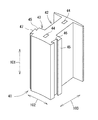
図1は、本発明の実施形態にかかるアウターロータ型車両用発電機10の外観構成を示す正面図である。図2は、アウターロータ型車両用発電機10の内部構成を示す縦断面図である。図3は、支持本体11の縦断面図である。図4は、ロータヨーク14の縦断面図である。図5は、図1におけるV−V切断線における断面図である。図6は、分割コア41の外観斜視図である。図7は、分割コア41の上面図である。図8は、アウターロータ型車両用発電機10の冷却作用を説明するための縦断面図である。
[Explanation of drawings]
FIG. 1 is a front view showing an external configuration of an outer rotor
[アウターロータ型車両用発電機10]
図1及び図2に示されるように、アウターロータ型車両用発電機10(以下「発電機10」とも称される。)は、支持本体11と、ステータコア12と、コイル13と、ロータヨーク14と、カバー15とを主要構成とする。発電機10は、自動車などの車両に搭載されて、自動車エンジンなどの駆動源から駆動伝達されて電磁誘導により発電を行う。この電磁誘導は、固定子としてステータコア12に巻装されたコイル13と、回転子としてステータコア12の外側で回転するロータヨーク14に設けられたマグネット63とを主要構成として行われる。
[Outer rotor type vehicle generator 10]
As shown in FIGS. 1 and 2, the outer rotor type vehicle generator 10 (hereinafter also referred to as “
[支持本体11]
図2及び図3に示されるように、支持本体11は、概ね円筒形状の芯部21と、側壁部22とに大別される。側壁部22は、芯部21の第2端24から芯部21の軸線101に対して直交する方向へ拡がる概ね矩形の壁である。この側壁部22は、後述されるカバー15と共に発電機10の筐体の一部をなす。側壁部22の周縁は、第1端23側へ向かって突出する係合部25が設けられている。この係合部25にカバー15が係合されて一体の筐体とされる。また、側壁部22における第1端23側には、軸線101から放射線状に延びる複数の補強リブ26が形成されている。
[Support body 11]
As shown in FIGS. 2 and 3, the support
芯部21は、概ね円筒形状をなしており、その外径によって径大部28と径小部29とに大別される。円筒形状の芯部21の中心が軸線101であり、この軸線101を中心として後述されるロータヨーク14が回転される。径大部28は後述されるステータコア12が圧入される部分であり、ステータコア12の中空部の内径に対応された外径である。径小部29は、2個のアンギュラー軸受30が設けられる部分であり、本発明における軸受け部に相当する。
The
径大部28には、第1段差部31が設けられている。この第1段差部31は、第1端23側に対して第2端24側の径が大きくされて構成されている。後述されるステータコア12は、第1端23側から径大部28に圧入されて、第1段差部31と係合される。この第1段差部31と、径大部28と径小部29との境界となる段差において軸線101に沿って螺合されるボルト27とによって、径大部28に圧入されたステータコア12が軸線101方向に対して固定される。
A
径小部29には、第2段差部32が設けられている。この第2段差部32は、第1端23側に対して第2端24側の径が大きくされて構成されている。各アンギュラー軸受30は、第1端23側から径小部29に挿入されて、第2段差部32と係合される。この第2段差部32と、第1端23側から径小部29に嵌め込まれたリング形状の留め具33とによって、径小部29に挿入された2個のアンギュラー軸受30が、軸線101方向に並列された状態で固定される。
The small-
芯部21の内空34は、第1端23側に対して封止されており、第2端24側に対して開口されている。この内空34は、第2端24から第1端23側へ向かって軸線101に沿って延び、径小部29の第2段差32付近が最奥とされて第1端23側に対して封止されている。また、径大部28から径小部29へと外径が小さくなるに対応して、内空34の内径も径大部と径小部とが形成されている。
The
内空34の最奥付近には、芯部21を径方向に貫通する通風口35が設けられている。この通風口35によって、内空34が芯部21の外側へ開口されている。つまり、第2端24側において芯部21の開口から内空34へ進入した外気は、第1端23側において通風口34,35を通じて芯部21の外側へ流出し得る。なお、各図には2つの通風口35のみが現れているが、通風口35は、軸線101を中心として放射線状に3個以上が配置され得る。
Near the innermost part of the
通風口35は、芯部21において、径大部28と径小部29の第2段差32との間に配置されている。図2に示されるように、この配置によって、通風口35は、ステータコア12とアンギュラー軸受30との間に配置される。
The
内空34の中心には、軸36が設けられている。軸36は、内空34の最奥から第2端24へ向かって軸線101に沿って突出された円柱形状の部材である。軸36と径大部28の内面及び径小部29の内面とは空隙が設けられている。したがって、軸36の周囲に内空34が形成される。各図には現れていないが、軸36から径大部28の内面に渡って補強リブが設けられることにより、芯部21の剛性が高められている。この補強リブは、内空34において、第2端24側の開口から各通風口35までの流路を塞がないように設けられる。
A
[ステータコア12及びコイル13]
図2及び図5に示されるように、ステータコア12は、支持本体11の芯部21の周囲を取り巻くように配置されている。そして、このステータコア12にコイル13が巻装されている。ステータコア12は、コイル13が巻装された18個の分割コア41が円環形状に連結されてなる。
[
As shown in FIGS. 2 and 5, the
ステータコア12を構成する18個の各分割コア41は、円環形状に連結される配置が異なる他は同形状のものであり、各分割コア41が連結されて1つの円環形状のステータコア12が構成されている。なお、本実施形態では、分割コア41は、ステータコア12が1個のティース部42毎に分割されたものであるが、分割コア41は必ずしも1個のティース部42毎に分割されたものである必要はなく、例えば、所定個数のティース部42毎にステータコア12が分割されたものであってもよい。
The 18 divided
図6及び図7に示されるように、分割コア41は、ティース部42とコアヨーク部43とに大別される。ティース部42には、コイル13が巻回される。コアヨーク部43は、他の分割コア41のコアヨーク部43と連結されて円環形状をなす。各コアヨーク部43は、円環形状のステータコア12の周方向の幅の18分の1となる弧状に形成されている。ティース部42は、コアヨーク部43からステータコア12の径方向外側へ突出しており、絶縁のためのインシュレータ等を介してコイル13が巻回される。このような分割コア41は、平面視において同一形状の複数の鋼板が軸線101方向に積層されて、半抜きされたカシメ部44が上下(軸線101方向)に積層された各鋼板と嵌合されることにより一体とされている。
As shown in FIGS. 6 and 7, the
コイル13の巻回は、各分割コア41が独立した状態、つまり円環形状に連結される前になされる。これにより、各分割コア41のティース部42周りに巻線作業のための空間が確保されるので、ティース部42にコイル13が密に巻回される。コイル13の巻回方法は特に限定されないが、フライヤ式又はノズル式の巻線機を用いて複数の分割コア41に対して1本の銅線を連続して巻回し、その複数の分割コア41をコイル13間の渡り線により連結させて1群のものとすれば、結線作業が簡略化されるので好適である。
The
分割コア41のコアヨーク部43が他の分割コア41のコアヨーク部43と隣接する各隣接面45には、係合凹部46及び係合凸部47がそれぞれ形成されている。各隣接面45は、ステータコア12のコアヨーク部43における周方向102の両端において、ステータコア12の軸線101方向及び径方向103へ延びる平面をなしている。係合凹部46及び係合凸部47は、各隣接面45において軸線101方向に沿って延出されている。
On each
図7に示されるように、係合凹部46及び係合凸部47は、所謂あり形状である。詳細に説明するに、係合凹部46は、コアヨーク部43の隣接面45からステータコア12の周方向102へ凹欠されたものである。係合凹部46が隣接面45に開口する開口部48の径方向103の幅W1に対して、係合凹部46の奥部49の径方向の幅W2が幅広となっており、開口部48から奥部49へは連続的に拡幅されるあり面50が形成されている。
As shown in FIG. 7, the engagement
係合凸部47は、コアヨーク部43の隣接面45からステータコア12の周方向102へ突出されたものである。係合凸部47の隣接面45に沿った基部51の径方向103の幅W1に対して、係合凸部47の先端部52の径方向の幅W2が幅広となっており、基部51から先端部52へは連続的に拡幅されるテーパ面53が形成されている。
The engaging
係合凹部46と係合凸部47とは、互いに対応した凹凸形状であり、係合凹部46及び係合凸部47は、隣接面45における径方向103の略中央に形成されている。係合凹部46及び係合凸部47が、それぞれ隣り合う他の分割コア41の係合凸部47又は係合凹部46と係合されて、18個の分割コア41がステータコア12として円環形状に組み付けられる。
The engaging
係合凹部46の開口部48の径方向の幅W1と係合凸部47の基部51の径方向の幅W1とは同寸法であり、また、係合凹部46の奥部49の径方向の幅W2と係合凸部47の先端部52の径方向の幅W2とは同寸法である。さらに、係合凹部46のあり面50と係合凸部47のテーパ面53とは同一の傾斜角度となっている。したがって、係合凹部46と係合凸部47とが係合し、この係合状態において、あり面50とテーパ面53とが面接触し、また、コアヨーク部43の隣接面45が、隣り合う他の分割コア41のコアヨーク部43の隣接面45と面接触する。
The radial width W1 of the
また、係合凹部46及び係合凸部47との係合はいわゆる隙間嵌めである。詳細に説明するに、係合凹部46の開口部48の径方向の幅W1及び奥部49の径方向の幅W2の公差がプラス側にされており、係合凸部47の基部51の径方向の幅W1及び先端部52の径方向の幅W2の公差がマイナス側にされている。これにより、係合凹部46と係合凸部47との係合に公差によるガタが生じる。このガタによって、積層鋼板からなる分割コア41において、係合凹部46と係合凸部47とを軸線101方向に相対移動させながら係合させる作業が容易となる。
Further, the engagement with the engagement
図5に示されるように、係合凹部46と係合凸部47との係合により、隣接する分割コア41は、ステータコア12の周方向102及び径方向103に対して互いのコアヨーク部43が固定される。すなわち、隣接する分割コア41のコアヨーク部43の各隣接面45が、その径方向103の両端を合致させた状態に維持される。
As shown in FIG. 5, due to the engagement of the engagement recesses 46 and the
18個の分割コア41が、互いの係合凹部46と係合凸部47とが係合されて組み付けると、コイル13が巻回されたティース部42が外側へ放射線状に突出された円環形状のステータコア12となる。この円環形状は、係合凹部46と係合凸部47との係合により維持されている。
When the 18 divided
円環形状に組み付けられたステータコア12の中空部分に、支持本体11の芯部21が圧入される。これにより、隙間嵌めによりガタが生じていた係合凹部46と係合凸部47との係合状態が密嵌状態となる。芯部21が圧入されることにより、円環形状に組み付けられた各分割コア41に対して径方向103の外側へ応力が負荷されるが、係合凹部46と係合凸部47との係合により、分割コア41が周方向102に対して離れるようにして径方向103の外側へ拡がることがない。また、係合凹部46及び係合凸部47は、分割コア41の隣接面45の径方向略中央に形成されているので、かかる応力が、各分割コア41の隣接面45に対して平均して負荷される。
The
[ロータヨーク14]
図2に示されるように、ロータヨーク14は、支持本体11の芯部21の径小部29においてアンギュラー軸受30を介して支持されることにより、軸線101を中心として回転自在に支持されている。図4に示されるように、ロータヨーク14は、プーリ61、ヨーク部62、マグネット63を主要な構成とする。
[Rotor yoke 14]
As shown in FIG. 2, the
プーリ61は、ロータヨーク14における第1端71側に設けられている。各図には示されていないが、プーリ61にはベルトが架け渡されて、そのベルトを介して自動車エンジンなどの駆動源から駆動伝達される。このプーリ61への駆動伝達によって、ロータヨーク14が軸線101を中心として回転される。プーリ61の内面側には、アンギュラー軸受30により支持される円周面64が形成されている。この円周面64には、第1端71側に小径となる段差65が形成されており、第2端72側にリング形状の留め具66(図2参照)が嵌め込まれる溝67が形成されている。図2に示されるように、溝67に嵌め込まれた留め具66と段差65とによって、アンギュラー軸受30が円周面64において軸線101方向に対して位置決めされる。なお、第1端71及び第2端72は、ロータヨーク14において軸線101方向の両端である。
The
ヨーク部62は、プーリ61から第2端72側へ向かって延びる円筒形状のものである。ヨーク部62は、壁部68と筒部69とを主要構成とする。ヨーク部62の外径は、プーリ61の外径より大きい。したがって、プーリ61から径方向外側へ拡がる円環形状の壁部68が設けられ、壁部68の周縁から軸線101方向へ延びる筒部69が設けられている。筒部69の第2端72側は開口されている。この筒部69の内径は、前述されたステータコア12の外径を考慮して、後述されるマグネット63がステータコア12に対して所定の磁気ギャップを隔てられて配置されるように設定されている。筒部69の第1端71側は、壁部68の中心側において開口されているが、図2に示されるように、ロータヨーク14が支持本体11に支持されると、内周面64にアンギュラー軸受30が接触し、そのアンギュラー軸受30の内側には芯部21の径小部29が配置されるので、これら径小部29及びアンギュラー軸受30により封止される。プーリ61とヨーク部62は、磁性材料が用いられて鋳型によって一体に形成されている。なお、プーリ61の径とヨーク部62の径は一例であり、例えば、プーリ61がヨーク部62に対して大径であってもよい。
The
ヨーク部62の筒部69の内面には、20極のマグネット63が円環形状に配列されて固定されている。マグネット63は、磁石粒子が焼結された永久磁石であり、図5に示されるように、周方向にN極とS極とが交互となって20極の磁極が形成されている。ヨーク部62に固定された各マグネット63は、前述されたステータコア12の外周面と所定の磁気ギャップが隔てられて対向される。
On the inner surface of the
なお、マグネット63は、円筒状に焼結された所謂リングマグネットや各磁極で分割されたもの等、周知の発電機用磁石を用いることができる。また、本実施形態では、20極・18スロットの発電機10が例として説明されているが、本発明においてアウターロータ型車両用発電機の極数及びスロット数は特に限定されるものではない。
The
ヨーク部62には、ヨーク部62と共に回転して第2端72側へ向かって送風するフィン70が設けられている。このフィン70は、ヨーク部62の内側において各々が軸線101に対して径方向へ延出された複数のものであって、軸線101を中心として放射状に配置されている。各フィン70は、軸線101に対する配置が異なる他は同一形状のものである。なお、各図においては2個のフィン70のみが現れている。
The
フィン70は、ヨーク部62の第1端71側に設けられた壁部68の内側から軸線101に沿って第2端72側へ延びている。軸線101に対する径方向において、フィン70の内側端は内周面67付近にあり、外側端は筒部69の内周面に到達している。つまり、フィン70は、軸線101に対する径方向へ延びるリブ形状である。フィン70における第2端72へ向かう先端73は、マグネット63から所定の距離を隔てられている。この所定の距離は、図2に示されるように、ステータコア12のコイル13などが占有する空間を考慮して、フィン70がコイル13などと接触しないように設定されている。このフィン70は、プーリ61及びヨーク部62と共に、磁性材料が用いられて鋳型によって一体に形成されている。
The
[カバー15]
図1,2,5に示されるように、支持本体11の側壁部22に係合されて、ロータヨーク14を径方向外側から覆うカバー15が設けられている。カバー15は、外側が角柱形状であって内側が円筒形状である。外側の角柱形状は、支持本体11の側壁部22に対応した形状及び寸法に設定されている。内側の円筒形状は、ロータヨーク14の外径より大径であって、ロータヨーク14との間に軸線101方向の間隙が形成される形状及び寸法に設定されている。カバー15の軸線101方向の寸法は、側壁部22に係合されたカバー15が、ロータヨーク14のヨーク部62を覆い、かつプーリ61を覆わない寸法に設定されている。また、図1に示されるように、このカバー15には、支持本体11の側壁部22付近において厚み方向に貫通される貫通孔81が複数設けられている、貫通孔81を通じて、カバー15の内外に水や気体が出入可能である。この貫通孔81は、万が一、カバー15の内側に水などが進入したときに、その水などを排出する目的で設けられるものであるが、必ずしも設けられなくてもよい。
[Cover 15]
As shown in FIGS. 1, 2, and 5, a
[発電機10における冷却作用]
前述されたように、ベルトを介して自動車エンジンなどの駆動源から駆動伝達されてプーリ61が回転すると、ヨーク部62に設けられたマグネット63も回転する。コイル13周りにマグネット63が回転すると、電磁誘導によりコイル13に電力が生じる。ヨーク部62の回転数は、自動車エンジンの種類やプーリ61の径などにもよるが、概ね1分間当たり数千回転から数万回転である。
[Cooling action in generator 10]
As described above, when driving is transmitted from a driving source such as an automobile engine via a belt and the
ヨーク部62が回転すると、その内側に設けられたフィン70も軸線101周りに回転する。このフィン70の回転によって、図8における各矢印で示されるように、ヨーク部62の内側において第1端71側から第2端72側へ向かって送風される。この送風によって、ヨーク部62の内側における第1端71側の気圧が下がると、芯部21の通風口35からヨーク部62の内側へ外気が吸い込まれる。これにより、外気が、第2端24側における芯部21の開口から芯部21の内空34及び通風口35を通じて、芯部21の径大部28と第2段差31との間からヨーク部62の内側へ流れ込み、さらにフィン70に送風されて、ステータコア12の各分割コア41の間やマグネット63との磁気ギャップを第1端71側から第2端72側へ流れる。そして、その外気がヨーク部62の第2端72を回り込んで、ヨーク部62とカバー15との隙間を第2端72側から第1端71側へ流れて外部へ排出される。なお、ヨーク部62の内側から流れ出た外気がカバー15の貫通孔81から外部へ排出されてもよい。このような外気の流れが連続することにより、ステータコア12が常に外気の流れに曝されて冷却される。
When the
[本実施形態の作用効果]
前述された発電機10によれば、支持本体11の芯部21において、第2端24側の開口を通じて芯部21の内空34に外気を進入させ、第1端23側において通風口35を通じて芯部21の外側へ流出させ、通風口35から流出した外気がフィン70に送風されて、ヨーク部62の内側においてステータコア12のティース部42の間やマグネット63との磁気ギャップをロータヨーク14の第1端71側から第2端72側へ流れ、ヨーク部62の先端である第2端72側から外部へ排出されるので、カバー15などに多数の貫通孔を設けることなく、内部部品を効果的に冷却することができる。これにより、水の進入による内部部品の腐食を抑制することができる。
[Operational effects of this embodiment]
According to the
また、ロータヨーク14に径方向の貫通孔を設ける必要がないので、ロータヨーク14の寸法精度を高めることが容易となり、ロータヨーク14にガタツキや軸ブレなどが生じることを抑制でき、支持本体11の径小部29においてロータヨーク14をいわゆる片持ちで軸支することが可能となる。
In addition, since it is not necessary to provide a through hole in the radial direction in the
また、アウターロータ型を採用しているので、永久磁石であるマグネット63を用いて、電磁石において必要とされる励磁電流を不要とできる。また、ロータヨーク14の内側にマグネット63が設けられているので、ロータヨーク14の回転によるマグネット63が飛散することがなく、高回転に耐え得る発電機10が実現される。
Further, since the outer rotor type is adopted, the
また、通風口35が、径小部29とステータコア14との間に配置されているので、通風口35からヨーク部62の内側へ導かれた外気をステータコア14に直接に送風させることができるので、冷却効率が向上される。
Further, since the
また、支持本体11に、ロータヨーク14を径方向外側から覆うカバー15が設けられているので、高速回転するロータヨーク14に人や工具が接触することを防止できる。さらに、カバー15に通気口としての貫通孔を多数設ける必要がないので、高速回転するロータヨーク14をカバー15によってほぼ完全に覆うことができるので、安全性が向上される。
In addition, since the
また、ステータコア12が分割コア41により構成され、各分割コア41が円環形状に連結される前にコイル13が巻回されることにより、各分割コア41のティース部42周りに巻線作業のための空間が確保されるので、ティース部42にコイル13が密に巻回される。
Further, the
また、係合凹部46及び係合凸部47とが隙間嵌めとされることにより、積層鋼板からなる分割コア41において、係合凹部46と係合凸部47とを軸線101方向に相対移動させながら係合させる作業が容易となる。そして、円環形状に組み付けられたステータコア12の中空部分に、支持本体11の芯部21が圧入されると、隙間嵌めされていた係合凹部46と係合凸部47との係合状態が密嵌状態となり、所望の外径のステータコア12が形成される。芯部21の圧入より各分割コア41に径方向103の外側への力が付加されるが、係合凹部46と係合凸部47との係合により、分割コア41が径方向103の外側へ拡がることがなく円環形状を維持する。これにより、アウターロータ型のステータコア12を簡易な構成として容易に組み付けることができる。
In addition, the
10・・・アウターロータ型車両用発電機
11・・・支持本体
12・・・ステータコア
13・・・コイル
14・・・ロータヨーク
15・・・カバー
21・・・芯部
23・・・第1端
24・・・第2端
29・・・径小部(軸受け部)
34・・・内空
35・・・通風口
41・・・分割コア
42・・・ティース部
43・・・コアヨーク部
45・・・隣接面
46・・・係合凹部
47・・・係合凸部
48・・・開口部
49・・・奥部
51・・・基部
52・・・先端部
61・・・プーリ
62・・・ヨーク部
63・・・マグネット
70・・・フィン
71・・・第1端
72・・・第2端
101・・・軸線
DESCRIPTION OF
34 ...
Claims (5)
上記支持本体の芯部の周囲に設けられたステータコアと、
上記ステータコアに巻装されたコイルと、
上記支持本体の軸受け部に回転自在に支持されており、上記第1端側にプーリが設けられ、かつ当該プーリ側から第2端側へ向かって延びて開口する筒形状のヨーク部の内側に、上記ステータコアと磁気ギャップを介して対向されるマグネットが設けられたロータヨークと、を具備し、
上記支持本体は、第1端側において上記芯部を径方向へ貫通する通風口が設けられており、
上記ロータヨークは、第2端側において軸方向に開口し、且つ上記ヨーク部の内側における第1端側に、ヨーク部と共に回転して第2端側の開口へ向かって送風するフィンが設けられたアウターロータ型車両用発電機。 A support body having a cylindrical core portion, a bearing portion is provided on the first end side in the axial direction of the core portion, and the inner space of the core portion is opened to the outside on the second end side;
A stator core provided around the core of the support body;
A coil wound around the stator core;
It is rotatably supported by the bearing portion of the support body, a pulley is provided on the first end side, and extends from the pulley side toward the second end side and opens inside a cylindrical yoke portion. A rotor yoke provided with a magnet opposed to the stator core via a magnetic gap,
The support body is provided with a vent hole penetrating the core portion in the radial direction on the first end side,
The rotor yoke is provided with an opening in the axial direction on the second end side, and a fin that rotates with the yoke portion and blows air toward the opening on the second end side on the first end side inside the yoke portion. Outer rotor type vehicle generator.
上記各分割コアは、上記コイルが巻回されるティース部と他の分割コアと連結されるコアヨーク部とをそれぞれ有する同一形状の複数の鋼板が積層されて一体に嵌合されたものであって、当該コアヨーク部において隣り合うコアヨーク部と隣接する隣接面に、相互に係合する係合凹部又は係合凸部のいずれか一方が形成されており、
上記係合凹部及び係合凸部は、上記隣接面から上記円環形状の配列における周方向へ凹凸して、当該隣接面に沿った開口部又は基部より奥部側又は先端部側が幅広のあり形状であって隙間嵌めとなる寸法であり、
円環形状に配列されて隙間嵌めされた分割コアの中空に上記支持本体の芯部が圧入された請求項1から4のいずれかに記載のアウターロータ型車両用発電機。
The stator core includes divided cores that are divided into predetermined teeth portions and arranged in an annular shape,
Each of the divided cores is formed by stacking and integrally fitting a plurality of steel plates having the same shape each having a tooth portion around which the coil is wound and a core yoke portion connected to another divided core. In the core yoke portion, the adjacent surface adjacent to the adjacent core yoke portion is formed with either one of the engagement concave portion or the engagement convex portion that engage with each other,
The engagement recess and the engagement protrusion are uneven in the circumferential direction in the annular array from the adjacent surface, and the back side or the tip side is wider than the opening or base along the adjacent surface. The shape is a dimension that fits into the gap,
The generator for an outer rotor type vehicle according to any one of claims 1 to 4, wherein the core portion of the support body is press-fitted into a hollow of the split cores arranged in an annular shape and fitted with a gap.
Priority Applications (1)
| Application Number | Priority Date | Filing Date | Title |
|---|---|---|---|
| JP2008181261A JP5202143B2 (en) | 2008-07-11 | 2008-07-11 | Outer rotor type vehicle generator |
Applications Claiming Priority (1)
| Application Number | Priority Date | Filing Date | Title |
|---|---|---|---|
| JP2008181261A JP5202143B2 (en) | 2008-07-11 | 2008-07-11 | Outer rotor type vehicle generator |
Publications (2)
| Publication Number | Publication Date |
|---|---|
| JP2010022148A JP2010022148A (en) | 2010-01-28 |
| JP5202143B2 true JP5202143B2 (en) | 2013-06-05 |
Family
ID=41706497
Family Applications (1)
| Application Number | Title | Priority Date | Filing Date |
|---|---|---|---|
| JP2008181261A Active JP5202143B2 (en) | 2008-07-11 | 2008-07-11 | Outer rotor type vehicle generator |
Country Status (1)
| Country | Link |
|---|---|
| JP (1) | JP5202143B2 (en) |
Families Citing this family (32)
| Publication number | Priority date | Publication date | Assignee | Title |
|---|---|---|---|---|
| US9552682B2 (en) | 2011-07-26 | 2017-01-24 | Gogoro Inc. | Apparatus, method and article for redistributing power storage devices, such as batteries, between collection, charging and distribution machines |
| US8560147B2 (en) | 2011-07-26 | 2013-10-15 | Gogoro, Inc. | Apparatus, method and article for physical security of power storage devices in vehicles |
| TWI576259B (en) | 2011-07-26 | 2017-04-01 | 睿能創意公司 | Thermal management of components in electric motor drive vehicles |
| JP6058665B2 (en) | 2011-07-26 | 2017-01-11 | ゴゴロ インク | Apparatus, method and article for collecting, charging and distributing power storage devices such as batteries |
| CN103843225B (en) | 2011-07-26 | 2018-01-23 | 睿能创意公司 | It is used for the certification of power storage device such as battery etc, the device of safety and control, method and article based on user profiles |
| TWI584976B (en) | 2011-07-26 | 2017-06-01 | 睿能創意公司 | Dynamically limiting vehicle operation for best effort economy |
| ES2939174T3 (en) | 2011-07-26 | 2023-04-19 | Gogoro Inc | Dynamic limitation of vehicle operation for a better economy of efforts |
| JP6026535B2 (en) | 2011-07-26 | 2016-11-16 | ゴゴロ インク | RESERVED POWER STORAGE DEVICE DEVICE, METHOD, AND ARTICLE FOR RESERVING A POWER STORAGE DEVICE IN A COLLECTION, CHARGING AND DISTRIBUTION MACHINE |
| WO2013016559A2 (en) | 2011-07-26 | 2013-01-31 | Gogoro, Inc. | Apparatus, method and article for a power storage device compartment |
| US10186094B2 (en) | 2011-07-26 | 2019-01-22 | Gogoro Inc. | Apparatus, method and article for providing locations of power storage device collection, charging and distribution machines |
| JP6096773B2 (en) | 2011-07-26 | 2017-03-15 | ゴゴロ インク | Apparatus, method, and article for authentication, security, and control of power storage devices such as batteries |
| CN103891088B (en) | 2011-07-26 | 2018-06-26 | 睿能创意公司 | For providing device, the method and article of the information related with the availability of the electrical energy storage at electrical energy storage collection, charging and dispenser |
| TW201330466A (en) * | 2011-10-12 | 2013-07-16 | Gogoro Inc | Electric device drive assembly and cooling system for electric device drive |
| WO2013179484A1 (en) * | 2012-06-01 | 2013-12-05 | 株式会社安川電機 | Motor stator, rotating motor, and method for manufacturing motor stator |
| DE102012106740A1 (en) * | 2012-07-25 | 2014-01-30 | Dr. Ing. H.C. F. Porsche Aktiengesellschaft | Electric machine for a hybrid or electric vehicle |
| JP5952714B2 (en) * | 2012-11-01 | 2016-07-13 | 川崎重工業株式会社 | Refrigerant supply / discharge device and superconducting rotating machine device including the same |
| US9216687B2 (en) | 2012-11-16 | 2015-12-22 | Gogoro Inc. | Apparatus, method and article for vehicle turn signals |
| DE102012112923A1 (en) | 2012-12-21 | 2014-06-26 | Dr. Ing. H.C. F. Porsche Aktiengesellschaft | Electric machine with cooling function for motor vehicle, has housing in form of pot-shape and including cooling ducts with cooling air, and air distribution channels trained in housing and arranged from simultaneous air feeding channel |
| US9854438B2 (en) | 2013-03-06 | 2017-12-26 | Gogoro Inc. | Apparatus, method and article for authentication, security and control of portable charging devices and power storage devices, such as batteries |
| US11710105B2 (en) | 2013-03-12 | 2023-07-25 | Gogoro Inc. | Apparatus, method and article for changing portable electrical power storage device exchange plans |
| US11222485B2 (en) | 2013-03-12 | 2022-01-11 | Gogoro Inc. | Apparatus, method and article for providing information regarding a vehicle via a mobile device |
| ES2802906T3 (en) | 2013-03-15 | 2021-01-21 | Gogoro Inc | Modular system for the collection and distribution of electrical storage devices |
| CN108189701B (en) | 2013-08-06 | 2021-10-22 | 睿能创意公司 | Electric vehicle system based on thermal profile adjustment of electric energy storage device |
| ES2735873T3 (en) | 2013-08-06 | 2019-12-20 | Gogoro Inc | Systems and methods to power electric vehicles that use a single or multiple power cells |
| US9124085B2 (en) | 2013-11-04 | 2015-09-01 | Gogoro Inc. | Apparatus, method and article for power storage device failure safety |
| WO2015070057A1 (en) | 2013-11-08 | 2015-05-14 | Gogoro Inc. | Apparatus, method and article for providing vehicle event data |
| JP6629213B2 (en) | 2014-01-23 | 2020-01-15 | ゴゴロ インク | Systems and methods utilizing arrays of power storage devices such as batteries |
| EP3180821B1 (en) | 2014-08-11 | 2019-02-27 | Gogoro Inc. | Multidirectional electrical connector and plug |
| USD789883S1 (en) | 2014-09-04 | 2017-06-20 | Gogoro Inc. | Collection, charging and distribution device for portable electrical energy storage devices |
| ES2934213T3 (en) | 2015-06-05 | 2023-02-20 | Gogoro Inc | Systems and methods for vehicle load detection and response |
| CN107659007A (en) * | 2017-11-03 | 2018-02-02 | 合普动力股份有限公司 | The fastening structure of split-type inner-stator iron core |
| KR102090569B1 (en) * | 2019-05-09 | 2020-03-18 | (주) 디엔디이 | Cooling structure of bulb hydraulic turbine generator and cooling method of bulb hydraulic turbine generator |
Family Cites Families (4)
| Publication number | Priority date | Publication date | Assignee | Title |
|---|---|---|---|---|
| JPS60128463U (en) * | 1984-01-31 | 1985-08-29 | 株式会社安川電機 | Cooling device for rotating electrical machines |
| JP3855689B2 (en) * | 2001-06-26 | 2006-12-13 | 国産電機株式会社 | Outer rotor type magnet generator with regulator |
| JP4286829B2 (en) * | 2005-03-24 | 2009-07-01 | 株式会社一宮電機 | Manufacturing method of rotating machine |
| JP4736025B2 (en) * | 2005-04-08 | 2011-07-27 | 日本精工株式会社 | Direct drive motor |
-
2008
- 2008-07-11 JP JP2008181261A patent/JP5202143B2/en active Active
Also Published As
| Publication number | Publication date |
|---|---|
| JP2010022148A (en) | 2010-01-28 |
Similar Documents
| Publication | Publication Date | Title |
|---|---|---|
| JP5202143B2 (en) | Outer rotor type vehicle generator | |
| US9729027B2 (en) | Cooling structure of rotary electric machine | |
| JP4560067B2 (en) | Rotating electric machine | |
| JP4949983B2 (en) | Rotating electric machine | |
| JP4661614B2 (en) | Cooling pipe fixing structure and electric vehicle | |
| JPS62221839A (en) | Ac generator for motor car | |
| EP3045725B1 (en) | Inflator having an enhanced cooling effect on a motor thereof | |
| JP2007074854A (en) | Rotating electric machine for vehicle | |
| JP5079006B2 (en) | Brushless AC generator for vehicles | |
| JP2008125330A (en) | Cooling structure for rotor, and method of manufacturing the rotor | |
| JP2007205246A (en) | Water pump and hybrid vehicle | |
| EP2988398B1 (en) | Rotating electric machine | |
| JP2009195082A (en) | Cooling structure of stator | |
| JP3876912B2 (en) | AC generator for vehicles | |
| JP3294497B2 (en) | Alternator | |
| JP2008054428A (en) | Ac generator for vehicle | |
| JP3656347B2 (en) | Rotating machine rotor | |
| JP5751319B2 (en) | Rotating electric machine | |
| JP6962772B2 (en) | Stator core cooling structure and rotary electric machine | |
| JP4424163B2 (en) | Vehicle alternator | |
| JP4394407B2 (en) | Vehicle alternator | |
| JP2012165488A (en) | Cooling device for rotary electric machine | |
| WO2023149551A1 (en) | Drive device | |
| US10305351B2 (en) | Rotating electrical machine for vehicle | |
| JP5404553B2 (en) | Rotating electric machine |
Legal Events
| Date | Code | Title | Description |
|---|---|---|---|
| A621 | Written request for application examination |
Free format text: JAPANESE INTERMEDIATE CODE: A621 Effective date: 20110125 |
|
| A977 | Report on retrieval |
Free format text: JAPANESE INTERMEDIATE CODE: A971007 Effective date: 20120704 |
|
| A131 | Notification of reasons for refusal |
Free format text: JAPANESE INTERMEDIATE CODE: A131 Effective date: 20120710 |
|
| A521 | Request for written amendment filed |
Free format text: JAPANESE INTERMEDIATE CODE: A523 Effective date: 20120904 |
|
| TRDD | Decision of grant or rejection written | ||
| A01 | Written decision to grant a patent or to grant a registration (utility model) |
Free format text: JAPANESE INTERMEDIATE CODE: A01 Effective date: 20130205 |
|
| A61 | First payment of annual fees (during grant procedure) |
Free format text: JAPANESE INTERMEDIATE CODE: A61 Effective date: 20130212 |
|
| R150 | Certificate of patent or registration of utility model |
Ref document number: 5202143 Country of ref document: JP Free format text: JAPANESE INTERMEDIATE CODE: R150 Free format text: JAPANESE INTERMEDIATE CODE: R150 |
|
| FPAY | Renewal fee payment (event date is renewal date of database) |
Free format text: PAYMENT UNTIL: 20160222 Year of fee payment: 3 |
|
| R250 | Receipt of annual fees |
Free format text: JAPANESE INTERMEDIATE CODE: R250 |
|
| R250 | Receipt of annual fees |
Free format text: JAPANESE INTERMEDIATE CODE: R250 |
|
| R250 | Receipt of annual fees |
Free format text: JAPANESE INTERMEDIATE CODE: R250 |
|
| R250 | Receipt of annual fees |
Free format text: JAPANESE INTERMEDIATE CODE: R250 |
|
| R250 | Receipt of annual fees |
Free format text: JAPANESE INTERMEDIATE CODE: R250 |
|
| R250 | Receipt of annual fees |
Free format text: JAPANESE INTERMEDIATE CODE: R250 |
|
| R250 | Receipt of annual fees |
Free format text: JAPANESE INTERMEDIATE CODE: R250 |
|
| R250 | Receipt of annual fees |
Free format text: JAPANESE INTERMEDIATE CODE: R250 |
|
| R250 | Receipt of annual fees |
Free format text: JAPANESE INTERMEDIATE CODE: R250 |