JP5201841B2 - Method for manufacturing display device - Google Patents
Method for manufacturing display device Download PDFInfo
- Publication number
- JP5201841B2 JP5201841B2 JP2007015503A JP2007015503A JP5201841B2 JP 5201841 B2 JP5201841 B2 JP 5201841B2 JP 2007015503 A JP2007015503 A JP 2007015503A JP 2007015503 A JP2007015503 A JP 2007015503A JP 5201841 B2 JP5201841 B2 JP 5201841B2
- Authority
- JP
- Japan
- Prior art keywords
- layer
- semiconductor layer
- region
- thin film
- display device
- Prior art date
- Legal status (The legal status is an assumption and is not a legal conclusion. Google has not performed a legal analysis and makes no representation as to the accuracy of the status listed.)
- Expired - Fee Related
Links
- 238000000034 method Methods 0.000 title claims description 235
- 238000004519 manufacturing process Methods 0.000 title claims description 40
- 239000004065 semiconductor Substances 0.000 claims description 362
- 239000012535 impurity Substances 0.000 claims description 229
- 238000005530 etching Methods 0.000 claims description 45
- 230000008569 process Effects 0.000 claims description 29
- VYPSYNLAJGMNEJ-UHFFFAOYSA-N Silicium dioxide Chemical compound O=[Si]=O VYPSYNLAJGMNEJ-UHFFFAOYSA-N 0.000 claims description 28
- 229910052814 silicon oxide Inorganic materials 0.000 claims description 25
- 238000009832 plasma treatment Methods 0.000 claims description 21
- 229910052581 Si3N4 Inorganic materials 0.000 claims description 18
- HQVNEWCFYHHQES-UHFFFAOYSA-N silicon nitride Chemical compound N12[Si]34N5[Si]62N3[Si]51N64 HQVNEWCFYHHQES-UHFFFAOYSA-N 0.000 claims description 18
- 229910052731 fluorine Inorganic materials 0.000 claims description 12
- 239000011737 fluorine Substances 0.000 claims description 12
- 230000001678 irradiating effect Effects 0.000 claims description 5
- 238000009413 insulation Methods 0.000 claims description 4
- PXGOKWXKJXAPGV-UHFFFAOYSA-N Fluorine Chemical compound FF PXGOKWXKJXAPGV-UHFFFAOYSA-N 0.000 claims 3
- 239000010410 layer Substances 0.000 description 978
- 239000010409 thin film Substances 0.000 description 276
- 239000010408 film Substances 0.000 description 274
- 239000000463 material Substances 0.000 description 133
- 239000000758 substrate Substances 0.000 description 113
- 230000015572 biosynthetic process Effects 0.000 description 61
- 239000007789 gas Substances 0.000 description 55
- 229920005989 resin Polymers 0.000 description 49
- 239000011347 resin Substances 0.000 description 49
- 230000006870 function Effects 0.000 description 41
- 239000004973 liquid crystal related substance Substances 0.000 description 39
- 238000010438 heat treatment Methods 0.000 description 37
- IJGRMHOSHXDMSA-UHFFFAOYSA-N Atomic nitrogen Chemical compound N#N IJGRMHOSHXDMSA-UHFFFAOYSA-N 0.000 description 34
- 150000002894 organic compounds Chemical group 0.000 description 34
- 239000000126 substance Substances 0.000 description 33
- -1 fluorinated arylene ether Chemical compound 0.000 description 32
- 229910052751 metal Inorganic materials 0.000 description 28
- 239000002184 metal Substances 0.000 description 28
- 239000002585 base Substances 0.000 description 27
- 238000012545 processing Methods 0.000 description 27
- 229910052760 oxygen Inorganic materials 0.000 description 26
- 239000001301 oxygen Substances 0.000 description 26
- PXHVJJICTQNCMI-UHFFFAOYSA-N Nickel Chemical compound [Ni] PXHVJJICTQNCMI-UHFFFAOYSA-N 0.000 description 25
- 229910010272 inorganic material Inorganic materials 0.000 description 24
- 229910052757 nitrogen Inorganic materials 0.000 description 24
- 229910021332 silicide Inorganic materials 0.000 description 24
- QVGXLLKOCUKJST-UHFFFAOYSA-N atomic oxygen Chemical compound [O] QVGXLLKOCUKJST-UHFFFAOYSA-N 0.000 description 23
- 239000010936 titanium Substances 0.000 description 23
- 229910052782 aluminium Inorganic materials 0.000 description 22
- 229910052799 carbon Inorganic materials 0.000 description 21
- BASFCYQUMIYNBI-UHFFFAOYSA-N platinum Chemical compound [Pt] BASFCYQUMIYNBI-UHFFFAOYSA-N 0.000 description 21
- 239000011159 matrix material Substances 0.000 description 20
- XAGFODPZIPBFFR-UHFFFAOYSA-N aluminium Chemical compound [Al] XAGFODPZIPBFFR-UHFFFAOYSA-N 0.000 description 19
- 238000005229 chemical vapour deposition Methods 0.000 description 19
- 238000002425 crystallisation Methods 0.000 description 19
- 239000001257 hydrogen Substances 0.000 description 19
- 229910052739 hydrogen Inorganic materials 0.000 description 19
- 229910052710 silicon Inorganic materials 0.000 description 19
- 238000004544 sputter deposition Methods 0.000 description 19
- XUIMIQQOPSSXEZ-UHFFFAOYSA-N Silicon Chemical compound [Si] XUIMIQQOPSSXEZ-UHFFFAOYSA-N 0.000 description 18
- 150000001875 compounds Chemical class 0.000 description 18
- 238000002347 injection Methods 0.000 description 18
- 239000007924 injection Substances 0.000 description 18
- 239000010703 silicon Substances 0.000 description 18
- OKTJSMMVPCPJKN-UHFFFAOYSA-N Carbon Chemical compound [C] OKTJSMMVPCPJKN-UHFFFAOYSA-N 0.000 description 17
- 239000010949 copper Substances 0.000 description 17
- 230000008025 crystallization Effects 0.000 description 17
- 150000002484 inorganic compounds Chemical class 0.000 description 17
- 238000007789 sealing Methods 0.000 description 17
- 239000011230 binding agent Substances 0.000 description 16
- 239000000460 chlorine Substances 0.000 description 15
- KPUWHANPEXNPJT-UHFFFAOYSA-N disiloxane Chemical class [SiH3]O[SiH3] KPUWHANPEXNPJT-UHFFFAOYSA-N 0.000 description 15
- FVBUAEGBCNSCDD-UHFFFAOYSA-N silicide(4-) Chemical compound [Si-4] FVBUAEGBCNSCDD-UHFFFAOYSA-N 0.000 description 15
- 229910052721 tungsten Inorganic materials 0.000 description 15
- UFHFLCQGNIYNRP-UHFFFAOYSA-N Hydrogen Chemical compound [H][H] UFHFLCQGNIYNRP-UHFFFAOYSA-N 0.000 description 14
- 230000003647 oxidation Effects 0.000 description 14
- 238000007254 oxidation reaction Methods 0.000 description 14
- 238000005268 plasma chemical vapour deposition Methods 0.000 description 14
- 229910052719 titanium Inorganic materials 0.000 description 14
- 230000000694 effects Effects 0.000 description 13
- 229910052759 nickel Inorganic materials 0.000 description 13
- 239000000956 alloy Substances 0.000 description 12
- 239000013078 crystal Substances 0.000 description 12
- 238000007740 vapor deposition Methods 0.000 description 12
- GWEVSGVZZGPLCZ-UHFFFAOYSA-N Titan oxide Chemical compound O=[Ti]=O GWEVSGVZZGPLCZ-UHFFFAOYSA-N 0.000 description 11
- 239000012298 atmosphere Substances 0.000 description 11
- 239000002131 composite material Substances 0.000 description 11
- 229910052802 copper Inorganic materials 0.000 description 11
- 230000007423 decrease Effects 0.000 description 11
- 239000000945 filler Substances 0.000 description 11
- 239000011521 glass Substances 0.000 description 11
- 229910003437 indium oxide Inorganic materials 0.000 description 11
- PJXISJQVUVHSOJ-UHFFFAOYSA-N indium(iii) oxide Chemical compound [O-2].[O-2].[O-2].[In+3].[In+3] PJXISJQVUVHSOJ-UHFFFAOYSA-N 0.000 description 11
- QGLKJKCYBOYXKC-UHFFFAOYSA-N nonaoxidotritungsten Chemical compound O=[W]1(=O)O[W](=O)(=O)O[W](=O)(=O)O1 QGLKJKCYBOYXKC-UHFFFAOYSA-N 0.000 description 11
- 239000011368 organic material Substances 0.000 description 11
- 229910052697 platinum Inorganic materials 0.000 description 11
- 229910052709 silver Inorganic materials 0.000 description 11
- 239000000243 solution Substances 0.000 description 11
- 239000010937 tungsten Substances 0.000 description 11
- 229910001930 tungsten oxide Inorganic materials 0.000 description 11
- 239000004642 Polyimide Substances 0.000 description 10
- RTAQQCXQSZGOHL-UHFFFAOYSA-N Titanium Chemical compound [Ti] RTAQQCXQSZGOHL-UHFFFAOYSA-N 0.000 description 10
- 239000003990 capacitor Substances 0.000 description 10
- 239000011651 chromium Substances 0.000 description 10
- 230000005684 electric field Effects 0.000 description 10
- 239000010931 gold Substances 0.000 description 10
- AMGQUBHHOARCQH-UHFFFAOYSA-N indium;oxotin Chemical compound [In].[Sn]=O AMGQUBHHOARCQH-UHFFFAOYSA-N 0.000 description 10
- 238000004518 low pressure chemical vapour deposition Methods 0.000 description 10
- 229920001721 polyimide Polymers 0.000 description 10
- 238000007639 printing Methods 0.000 description 10
- WFKWXMTUELFFGS-UHFFFAOYSA-N tungsten Chemical compound [W] WFKWXMTUELFFGS-UHFFFAOYSA-N 0.000 description 10
- YCKRFDGAMUMZLT-UHFFFAOYSA-N Fluorine atom Chemical compound [F] YCKRFDGAMUMZLT-UHFFFAOYSA-N 0.000 description 9
- 229910045601 alloy Inorganic materials 0.000 description 9
- 239000000919 ceramic Substances 0.000 description 9
- 238000006243 chemical reaction Methods 0.000 description 9
- 229910052737 gold Inorganic materials 0.000 description 9
- 239000011810 insulating material Substances 0.000 description 9
- 239000011777 magnesium Substances 0.000 description 9
- 239000002245 particle Substances 0.000 description 9
- 229910021420 polycrystalline silicon Inorganic materials 0.000 description 9
- 229920000642 polymer Polymers 0.000 description 9
- 239000002356 single layer Substances 0.000 description 9
- 239000007790 solid phase Substances 0.000 description 9
- 125000001424 substituent group Chemical group 0.000 description 9
- 229910052715 tantalum Inorganic materials 0.000 description 9
- ZAMOUSCENKQFHK-UHFFFAOYSA-N Chlorine atom Chemical compound [Cl] ZAMOUSCENKQFHK-UHFFFAOYSA-N 0.000 description 8
- RYGMFSIKBFXOCR-UHFFFAOYSA-N Copper Chemical compound [Cu] RYGMFSIKBFXOCR-UHFFFAOYSA-N 0.000 description 8
- KDLHZDBZIXYQEI-UHFFFAOYSA-N Palladium Chemical compound [Pd] KDLHZDBZIXYQEI-UHFFFAOYSA-N 0.000 description 8
- 229910052786 argon Inorganic materials 0.000 description 8
- 150000004945 aromatic hydrocarbons Chemical class 0.000 description 8
- 230000005540 biological transmission Effects 0.000 description 8
- 229910052791 calcium Inorganic materials 0.000 description 8
- 239000011575 calcium Substances 0.000 description 8
- 229910052801 chlorine Inorganic materials 0.000 description 8
- 229910052741 iridium Inorganic materials 0.000 description 8
- 150000004767 nitrides Chemical class 0.000 description 8
- 230000010355 oscillation Effects 0.000 description 8
- TWNQGVIAIRXVLR-UHFFFAOYSA-N oxo(oxoalumanyloxy)alumane Chemical compound O=[Al]O[Al]=O TWNQGVIAIRXVLR-UHFFFAOYSA-N 0.000 description 8
- 238000005192 partition Methods 0.000 description 8
- 238000005240 physical vapour deposition Methods 0.000 description 8
- 239000000565 sealant Substances 0.000 description 8
- YVTHLONGBIQYBO-UHFFFAOYSA-N zinc indium(3+) oxygen(2-) Chemical compound [O--].[Zn++].[In+3] YVTHLONGBIQYBO-UHFFFAOYSA-N 0.000 description 8
- BQCADISMDOOEFD-UHFFFAOYSA-N Silver Chemical compound [Ag] BQCADISMDOOEFD-UHFFFAOYSA-N 0.000 description 7
- 229910052804 chromium Inorganic materials 0.000 description 7
- 238000000576 coating method Methods 0.000 description 7
- PMHQVHHXPFUNSP-UHFFFAOYSA-M copper(1+);methylsulfanylmethane;bromide Chemical compound Br[Cu].CSC PMHQVHHXPFUNSP-UHFFFAOYSA-M 0.000 description 7
- 230000007547 defect Effects 0.000 description 7
- 230000009977 dual effect Effects 0.000 description 7
- 239000003822 epoxy resin Substances 0.000 description 7
- 238000001704 evaporation Methods 0.000 description 7
- 230000005284 excitation Effects 0.000 description 7
- 239000011147 inorganic material Substances 0.000 description 7
- 239000011229 interlayer Substances 0.000 description 7
- 150000002500 ions Chemical class 0.000 description 7
- 229910052698 phosphorus Inorganic materials 0.000 description 7
- 229920000647 polyepoxide Polymers 0.000 description 7
- 229920005591 polysilicon Polymers 0.000 description 7
- 239000004332 silver Substances 0.000 description 7
- OGIDPMRJRNCKJF-UHFFFAOYSA-N titanium oxide Inorganic materials [Ti]=O OGIDPMRJRNCKJF-UHFFFAOYSA-N 0.000 description 7
- NIXOWILDQLNWCW-UHFFFAOYSA-N 2-Propenoic acid Natural products OC(=O)C=C NIXOWILDQLNWCW-UHFFFAOYSA-N 0.000 description 6
- XKRFYHLGVUSROY-UHFFFAOYSA-N Argon Chemical compound [Ar] XKRFYHLGVUSROY-UHFFFAOYSA-N 0.000 description 6
- UHOVQNZJYSORNB-UHFFFAOYSA-N Benzene Chemical group C1=CC=CC=C1 UHOVQNZJYSORNB-UHFFFAOYSA-N 0.000 description 6
- GQPLMRYTRLFLPF-UHFFFAOYSA-N Nitrous Oxide Chemical compound [O-][N+]#N GQPLMRYTRLFLPF-UHFFFAOYSA-N 0.000 description 6
- OAICVXFJPJFONN-UHFFFAOYSA-N Phosphorus Chemical compound [P] OAICVXFJPJFONN-UHFFFAOYSA-N 0.000 description 6
- 125000004429 atom Chemical group 0.000 description 6
- 229910052796 boron Inorganic materials 0.000 description 6
- 125000001153 fluoro group Chemical group F* 0.000 description 6
- PCHJSUWPFVWCPO-UHFFFAOYSA-N gold Chemical compound [Au] PCHJSUWPFVWCPO-UHFFFAOYSA-N 0.000 description 6
- 230000005525 hole transport Effects 0.000 description 6
- AMWRITDGCCNYAT-UHFFFAOYSA-L hydroxy(oxo)manganese;manganese Chemical compound [Mn].O[Mn]=O.O[Mn]=O AMWRITDGCCNYAT-UHFFFAOYSA-L 0.000 description 6
- GKOZUEZYRPOHIO-UHFFFAOYSA-N iridium atom Chemical compound [Ir] GKOZUEZYRPOHIO-UHFFFAOYSA-N 0.000 description 6
- 229910052744 lithium Inorganic materials 0.000 description 6
- 229910052749 magnesium Inorganic materials 0.000 description 6
- 239000012299 nitrogen atmosphere Substances 0.000 description 6
- 238000007645 offset printing Methods 0.000 description 6
- 125000000962 organic group Chemical group 0.000 description 6
- 239000011574 phosphorus Substances 0.000 description 6
- 238000007650 screen-printing Methods 0.000 description 6
- 239000003566 sealing material Substances 0.000 description 6
- 230000005236 sound signal Effects 0.000 description 6
- 229920001187 thermosetting polymer Polymers 0.000 description 6
- 229910052718 tin Inorganic materials 0.000 description 6
- 239000011135 tin Substances 0.000 description 6
- 239000011701 zinc Substances 0.000 description 6
- UHXOHPVVEHBKKT-UHFFFAOYSA-N 1-(2,2-diphenylethenyl)-4-[4-(2,2-diphenylethenyl)phenyl]benzene Chemical group C=1C=C(C=2C=CC(C=C(C=3C=CC=CC=3)C=3C=CC=CC=3)=CC=2)C=CC=1C=C(C=1C=CC=CC=1)C1=CC=CC=C1 UHXOHPVVEHBKKT-UHFFFAOYSA-N 0.000 description 5
- ZOXJGFHDIHLPTG-UHFFFAOYSA-N Boron Chemical compound [B] ZOXJGFHDIHLPTG-UHFFFAOYSA-N 0.000 description 5
- OYPRJOBELJOOCE-UHFFFAOYSA-N Calcium Chemical compound [Ca] OYPRJOBELJOOCE-UHFFFAOYSA-N 0.000 description 5
- FYYHWMGAXLPEAU-UHFFFAOYSA-N Magnesium Chemical compound [Mg] FYYHWMGAXLPEAU-UHFFFAOYSA-N 0.000 description 5
- 229910052779 Neodymium Inorganic materials 0.000 description 5
- 229920000265 Polyparaphenylene Polymers 0.000 description 5
- UMIVXZPTRXBADB-UHFFFAOYSA-N benzocyclobutene Chemical compound C1=CC=C2CCC2=C1 UMIVXZPTRXBADB-UHFFFAOYSA-N 0.000 description 5
- IISBACLAFKSPIT-UHFFFAOYSA-N bisphenol A Chemical compound C=1C=C(O)C=CC=1C(C)(C)C1=CC=C(O)C=C1 IISBACLAFKSPIT-UHFFFAOYSA-N 0.000 description 5
- 238000010586 diagram Methods 0.000 description 5
- 238000010894 electron beam technology Methods 0.000 description 5
- 230000001747 exhibiting effect Effects 0.000 description 5
- 238000010304 firing Methods 0.000 description 5
- 229910052734 helium Inorganic materials 0.000 description 5
- 229910052743 krypton Inorganic materials 0.000 description 5
- 239000007788 liquid Substances 0.000 description 5
- 239000000203 mixture Substances 0.000 description 5
- 229910052750 molybdenum Inorganic materials 0.000 description 5
- 229910021421 monocrystalline silicon Inorganic materials 0.000 description 5
- 229920003986 novolac Polymers 0.000 description 5
- 230000001590 oxidative effect Effects 0.000 description 5
- 230000002093 peripheral effect Effects 0.000 description 5
- 229920003023 plastic Polymers 0.000 description 5
- 239000004033 plastic Substances 0.000 description 5
- 238000003746 solid phase reaction Methods 0.000 description 5
- 125000006850 spacer group Chemical group 0.000 description 5
- 125000000391 vinyl group Chemical group [H]C([*])=C([H])[H] 0.000 description 5
- VFUDMQLBKNMONU-UHFFFAOYSA-N 9-[4-(4-carbazol-9-ylphenyl)phenyl]carbazole Chemical group C12=CC=CC=C2C2=CC=CC=C2N1C1=CC=C(C=2C=CC(=CC=2)N2C3=CC=CC=C3C3=CC=CC=C32)C=C1 VFUDMQLBKNMONU-UHFFFAOYSA-N 0.000 description 4
- PIGFYZPCRLYGLF-UHFFFAOYSA-N Aluminum nitride Chemical compound [Al]#N PIGFYZPCRLYGLF-UHFFFAOYSA-N 0.000 description 4
- WHXSMMKQMYFTQS-UHFFFAOYSA-N Lithium Chemical compound [Li] WHXSMMKQMYFTQS-UHFFFAOYSA-N 0.000 description 4
- ZOKXTWBITQBERF-UHFFFAOYSA-N Molybdenum Chemical compound [Mo] ZOKXTWBITQBERF-UHFFFAOYSA-N 0.000 description 4
- ZCQWOFVYLHDMMC-UHFFFAOYSA-N Oxazole Chemical compound C1=COC=N1 ZCQWOFVYLHDMMC-UHFFFAOYSA-N 0.000 description 4
- 239000004695 Polyether sulfone Substances 0.000 description 4
- UCKMPCXJQFINFW-UHFFFAOYSA-N Sulphide Chemical compound [S-2] UCKMPCXJQFINFW-UHFFFAOYSA-N 0.000 description 4
- ATJFFYVFTNAWJD-UHFFFAOYSA-N Tin Chemical compound [Sn] ATJFFYVFTNAWJD-UHFFFAOYSA-N 0.000 description 4
- XLOMVQKBTHCTTD-UHFFFAOYSA-N Zinc monoxide Chemical compound [Zn]=O XLOMVQKBTHCTTD-UHFFFAOYSA-N 0.000 description 4
- 229910052788 barium Inorganic materials 0.000 description 4
- QVQLCTNNEUAWMS-UHFFFAOYSA-N barium oxide Chemical compound [Ba]=O QVQLCTNNEUAWMS-UHFFFAOYSA-N 0.000 description 4
- XJHCXCQVJFPJIK-UHFFFAOYSA-M caesium fluoride Chemical compound [F-].[Cs+] XJHCXCQVJFPJIK-UHFFFAOYSA-M 0.000 description 4
- 239000003086 colorant Substances 0.000 description 4
- 239000004020 conductor Substances 0.000 description 4
- 238000000151 deposition Methods 0.000 description 4
- 230000006866 deterioration Effects 0.000 description 4
- 238000007598 dipping method Methods 0.000 description 4
- 238000001312 dry etching Methods 0.000 description 4
- 230000007274 generation of a signal involved in cell-cell signaling Effects 0.000 description 4
- 229910052736 halogen Inorganic materials 0.000 description 4
- 150000002367 halogens Chemical class 0.000 description 4
- LNEPOXFFQSENCJ-UHFFFAOYSA-N haloperidol Chemical compound C1CC(O)(C=2C=CC(Cl)=CC=2)CCN1CCCC(=O)C1=CC=C(F)C=C1 LNEPOXFFQSENCJ-UHFFFAOYSA-N 0.000 description 4
- 150000002431 hydrogen Chemical class 0.000 description 4
- 239000011733 molybdenum Substances 0.000 description 4
- 229910000476 molybdenum oxide Inorganic materials 0.000 description 4
- 229910052754 neon Inorganic materials 0.000 description 4
- QJGQUHMNIGDVPM-UHFFFAOYSA-N nitrogen group Chemical group [N] QJGQUHMNIGDVPM-UHFFFAOYSA-N 0.000 description 4
- BPUBBGLMJRNUCC-UHFFFAOYSA-N oxygen(2-);tantalum(5+) Chemical compound [O-2].[O-2].[O-2].[O-2].[O-2].[Ta+5].[Ta+5] BPUBBGLMJRNUCC-UHFFFAOYSA-N 0.000 description 4
- 229910052763 palladium Inorganic materials 0.000 description 4
- 238000002161 passivation Methods 0.000 description 4
- 238000001020 plasma etching Methods 0.000 description 4
- 229920003207 poly(ethylene-2,6-naphthalate) Polymers 0.000 description 4
- 229920000553 poly(phenylenevinylene) Polymers 0.000 description 4
- 229920006393 polyether sulfone Polymers 0.000 description 4
- 239000011112 polyethylene naphthalate Substances 0.000 description 4
- 229920000139 polyethylene terephthalate Polymers 0.000 description 4
- 239000005020 polyethylene terephthalate Substances 0.000 description 4
- 229920002098 polyfluorene Polymers 0.000 description 4
- 229920001709 polysilazane Polymers 0.000 description 4
- 229920000123 polythiophene Polymers 0.000 description 4
- 230000006798 recombination Effects 0.000 description 4
- 238000005215 recombination Methods 0.000 description 4
- 230000002441 reversible effect Effects 0.000 description 4
- 239000010948 rhodium Substances 0.000 description 4
- 238000004528 spin coating Methods 0.000 description 4
- GUVRBAGPIYLISA-UHFFFAOYSA-N tantalum atom Chemical compound [Ta] GUVRBAGPIYLISA-UHFFFAOYSA-N 0.000 description 4
- 238000001039 wet etching Methods 0.000 description 4
- 229910052724 xenon Inorganic materials 0.000 description 4
- 229910052725 zinc Inorganic materials 0.000 description 4
- POILWHVDKZOXJZ-ARJAWSKDSA-M (z)-4-oxopent-2-en-2-olate Chemical compound C\C([O-])=C\C(C)=O POILWHVDKZOXJZ-ARJAWSKDSA-M 0.000 description 3
- SPDPTFAJSFKAMT-UHFFFAOYSA-N 1-n-[4-[4-(n-[4-(3-methyl-n-(3-methylphenyl)anilino)phenyl]anilino)phenyl]phenyl]-4-n,4-n-bis(3-methylphenyl)-1-n-phenylbenzene-1,4-diamine Chemical compound CC1=CC=CC(N(C=2C=CC(=CC=2)N(C=2C=CC=CC=2)C=2C=CC(=CC=2)C=2C=CC(=CC=2)N(C=2C=CC=CC=2)C=2C=CC(=CC=2)N(C=2C=C(C)C=CC=2)C=2C=C(C)C=CC=2)C=2C=C(C)C=CC=2)=C1 SPDPTFAJSFKAMT-UHFFFAOYSA-N 0.000 description 3
- ZVFQEOPUXVPSLB-UHFFFAOYSA-N 3-(4-tert-butylphenyl)-4-phenyl-5-(4-phenylphenyl)-1,2,4-triazole Chemical compound C1=CC(C(C)(C)C)=CC=C1C(N1C=2C=CC=CC=2)=NN=C1C1=CC=C(C=2C=CC=CC=2)C=C1 ZVFQEOPUXVPSLB-UHFFFAOYSA-N 0.000 description 3
- DHDHJYNTEFLIHY-UHFFFAOYSA-N 4,7-diphenyl-1,10-phenanthroline Chemical compound C1=CC=CC=C1C1=CC=NC2=C1C=CC1=C(C=3C=CC=CC=3)C=CN=C21 DHDHJYNTEFLIHY-UHFFFAOYSA-N 0.000 description 3
- 239000004925 Acrylic resin Substances 0.000 description 3
- 229920000178 Acrylic resin Polymers 0.000 description 3
- VYZAMTAEIAYCRO-UHFFFAOYSA-N Chromium Chemical compound [Cr] VYZAMTAEIAYCRO-UHFFFAOYSA-N 0.000 description 3
- 229910052691 Erbium Inorganic materials 0.000 description 3
- XEEYBQQBJWHFJM-UHFFFAOYSA-N Iron Chemical compound [Fe] XEEYBQQBJWHFJM-UHFFFAOYSA-N 0.000 description 3
- 229920000877 Melamine resin Polymers 0.000 description 3
- 239000004952 Polyamide Substances 0.000 description 3
- 239000004372 Polyvinyl alcohol Substances 0.000 description 3
- 229910003902 SiCl 4 Inorganic materials 0.000 description 3
- 229910002808 Si–O–Si Inorganic materials 0.000 description 3
- 229910052775 Thulium Inorganic materials 0.000 description 3
- NRTOMJZYCJJWKI-UHFFFAOYSA-N Titanium nitride Chemical compound [Ti]#N NRTOMJZYCJJWKI-UHFFFAOYSA-N 0.000 description 3
- 239000007983 Tris buffer Substances 0.000 description 3
- 229910052769 Ytterbium Inorganic materials 0.000 description 3
- 239000005083 Zinc sulfide Substances 0.000 description 3
- 230000001133 acceleration Effects 0.000 description 3
- CUJRVFIICFDLGR-UHFFFAOYSA-N acetylacetonate Chemical compound CC(=O)[CH-]C(C)=O CUJRVFIICFDLGR-UHFFFAOYSA-N 0.000 description 3
- 229910052783 alkali metal Inorganic materials 0.000 description 3
- 150000001340 alkali metals Chemical class 0.000 description 3
- 229910052784 alkaline earth metal Inorganic materials 0.000 description 3
- 150000001342 alkaline earth metals Chemical class 0.000 description 3
- 125000000217 alkyl group Chemical group 0.000 description 3
- 150000001408 amides Chemical class 0.000 description 3
- 230000003321 amplification Effects 0.000 description 3
- 229910052785 arsenic Inorganic materials 0.000 description 3
- DSAJWYNOEDNPEQ-UHFFFAOYSA-N barium atom Chemical compound [Ba] DSAJWYNOEDNPEQ-UHFFFAOYSA-N 0.000 description 3
- 239000000872 buffer Substances 0.000 description 3
- 230000015556 catabolic process Effects 0.000 description 3
- 230000008859 change Effects 0.000 description 3
- 239000011248 coating agent Substances 0.000 description 3
- 229910017052 cobalt Inorganic materials 0.000 description 3
- 239000010941 cobalt Substances 0.000 description 3
- GUTLYIVDDKVIGB-UHFFFAOYSA-N cobalt atom Chemical compound [Co] GUTLYIVDDKVIGB-UHFFFAOYSA-N 0.000 description 3
- 150000004696 coordination complex Chemical class 0.000 description 3
- 239000010432 diamond Substances 0.000 description 3
- 229910003460 diamond Inorganic materials 0.000 description 3
- 238000009792 diffusion process Methods 0.000 description 3
- 239000002019 doping agent Substances 0.000 description 3
- 229910052733 gallium Inorganic materials 0.000 description 3
- 230000012447 hatching Effects 0.000 description 3
- 229910052738 indium Inorganic materials 0.000 description 3
- 239000011261 inert gas Substances 0.000 description 3
- 239000007791 liquid phase Substances 0.000 description 3
- 229910044991 metal oxide Inorganic materials 0.000 description 3
- 150000004706 metal oxides Chemical class 0.000 description 3
- 150000002739 metals Chemical class 0.000 description 3
- 238000002156 mixing Methods 0.000 description 3
- 239000004570 mortar (masonry) Substances 0.000 description 3
- 239000010955 niobium Substances 0.000 description 3
- 238000005121 nitriding Methods 0.000 description 3
- 229960001730 nitrous oxide Drugs 0.000 description 3
- 238000003199 nucleic acid amplification method Methods 0.000 description 3
- 230000003287 optical effect Effects 0.000 description 3
- SIWVEOZUMHYXCS-UHFFFAOYSA-N oxo(oxoyttriooxy)yttrium Chemical compound O=[Y]O[Y]=O SIWVEOZUMHYXCS-UHFFFAOYSA-N 0.000 description 3
- PQQKPALAQIIWST-UHFFFAOYSA-N oxomolybdenum Chemical compound [Mo]=O PQQKPALAQIIWST-UHFFFAOYSA-N 0.000 description 3
- RVTZCBVAJQQJTK-UHFFFAOYSA-N oxygen(2-);zirconium(4+) Chemical compound [O-2].[O-2].[Zr+4] RVTZCBVAJQQJTK-UHFFFAOYSA-N 0.000 description 3
- 239000012071 phase Substances 0.000 description 3
- 239000005011 phenolic resin Substances 0.000 description 3
- 238000000206 photolithography Methods 0.000 description 3
- 229920002647 polyamide Polymers 0.000 description 3
- 229920002577 polybenzoxazole Polymers 0.000 description 3
- 229920002451 polyvinyl alcohol Polymers 0.000 description 3
- 238000010791 quenching Methods 0.000 description 3
- 150000003254 radicals Chemical class 0.000 description 3
- 230000009467 reduction Effects 0.000 description 3
- 238000002310 reflectometry Methods 0.000 description 3
- 230000003252 repetitive effect Effects 0.000 description 3
- 229910052703 rhodium Inorganic materials 0.000 description 3
- 239000010944 silver (metal) Substances 0.000 description 3
- 238000010532 solid phase synthesis reaction Methods 0.000 description 3
- 239000002904 solvent Substances 0.000 description 3
- 229920003002 synthetic resin Polymers 0.000 description 3
- 239000000057 synthetic resin Substances 0.000 description 3
- 229920002803 thermoplastic polyurethane Polymers 0.000 description 3
- 229910001935 vanadium oxide Inorganic materials 0.000 description 3
- 229910052984 zinc sulfide Inorganic materials 0.000 description 3
- SKJCKYVIQGBWTN-UHFFFAOYSA-N (4-hydroxyphenyl) methanesulfonate Chemical compound CS(=O)(=O)OC1=CC=C(O)C=C1 SKJCKYVIQGBWTN-UHFFFAOYSA-N 0.000 description 2
- PFNQVRZLDWYSCW-UHFFFAOYSA-N (fluoren-9-ylideneamino) n-naphthalen-1-ylcarbamate Chemical compound C12=CC=CC=C2C2=CC=CC=C2C1=NOC(=O)NC1=CC=CC2=CC=CC=C12 PFNQVRZLDWYSCW-UHFFFAOYSA-N 0.000 description 2
- RTSZQXSYCGBHMO-UHFFFAOYSA-N 1,2,4-trichloro-3-prop-1-ynoxybenzene Chemical compound CC#COC1=C(Cl)C=CC(Cl)=C1Cl RTSZQXSYCGBHMO-UHFFFAOYSA-N 0.000 description 2
- XOYZGLGJSAZOAG-UHFFFAOYSA-N 1-n,1-n,4-n-triphenyl-4-n-[4-[4-(n-[4-(n-phenylanilino)phenyl]anilino)phenyl]phenyl]benzene-1,4-diamine Chemical group C1=CC=CC=C1N(C=1C=CC(=CC=1)N(C=1C=CC=CC=1)C=1C=CC(=CC=1)C=1C=CC(=CC=1)N(C=1C=CC=CC=1)C=1C=CC(=CC=1)N(C=1C=CC=CC=1)C=1C=CC=CC=1)C1=CC=CC=C1 XOYZGLGJSAZOAG-UHFFFAOYSA-N 0.000 description 2
- IYZMXHQDXZKNCY-UHFFFAOYSA-N 1-n,1-n-diphenyl-4-n,4-n-bis[4-(n-phenylanilino)phenyl]benzene-1,4-diamine Chemical compound C1=CC=CC=C1N(C=1C=CC(=CC=1)N(C=1C=CC(=CC=1)N(C=1C=CC=CC=1)C=1C=CC=CC=1)C=1C=CC(=CC=1)N(C=1C=CC=CC=1)C=1C=CC=CC=1)C1=CC=CC=C1 IYZMXHQDXZKNCY-UHFFFAOYSA-N 0.000 description 2
- BFTIPCRZWILUIY-UHFFFAOYSA-N 2,5,8,11-tetratert-butylperylene Chemical group CC(C)(C)C1=CC(C2=CC(C(C)(C)C)=CC=3C2=C2C=C(C=3)C(C)(C)C)=C3C2=CC(C(C)(C)C)=CC3=C1 BFTIPCRZWILUIY-UHFFFAOYSA-N 0.000 description 2
- UOCMXZLNHQBBOS-UHFFFAOYSA-N 2-(1,3-benzoxazol-2-yl)phenol zinc Chemical compound [Zn].Oc1ccccc1-c1nc2ccccc2o1.Oc1ccccc1-c1nc2ccccc2o1 UOCMXZLNHQBBOS-UHFFFAOYSA-N 0.000 description 2
- FQJQNLKWTRGIEB-UHFFFAOYSA-N 2-(4-tert-butylphenyl)-5-[3-[5-(4-tert-butylphenyl)-1,3,4-oxadiazol-2-yl]phenyl]-1,3,4-oxadiazole Chemical compound C1=CC(C(C)(C)C)=CC=C1C1=NN=C(C=2C=C(C=CC=2)C=2OC(=NN=2)C=2C=CC(=CC=2)C(C)(C)C)O1 FQJQNLKWTRGIEB-UHFFFAOYSA-N 0.000 description 2
- POXIZPBFFUKMEQ-UHFFFAOYSA-N 2-cyanoethenylideneazanide Chemical group [N-]=C=[C+]C#N POXIZPBFFUKMEQ-UHFFFAOYSA-N 0.000 description 2
- OBAJPWYDYFEBTF-UHFFFAOYSA-N 2-tert-butyl-9,10-dinaphthalen-2-ylanthracene Chemical compound C1=CC=CC2=CC(C3=C4C=CC=CC4=C(C=4C=C5C=CC=CC5=CC=4)C4=CC=C(C=C43)C(C)(C)C)=CC=C21 OBAJPWYDYFEBTF-UHFFFAOYSA-N 0.000 description 2
- WUPHOULIZUERAE-UHFFFAOYSA-N 3-(oxolan-2-yl)propanoic acid Chemical compound OC(=O)CCC1CCCO1 WUPHOULIZUERAE-UHFFFAOYSA-N 0.000 description 2
- QYNTUCBQEHUHCS-UHFFFAOYSA-N 4-n-(3-methylphenyl)-1-n-[4-[4-(n-[4-(n-(3-methylphenyl)anilino)phenyl]anilino)phenyl]phenyl]-1-n,4-n-diphenylbenzene-1,4-diamine Chemical group CC1=CC=CC(N(C=2C=CC=CC=2)C=2C=CC(=CC=2)N(C=2C=CC=CC=2)C=2C=CC(=CC=2)C=2C=CC(=CC=2)N(C=2C=CC=CC=2)C=2C=CC(=CC=2)N(C=2C=CC=CC=2)C=2C=C(C)C=CC=2)=C1 QYNTUCBQEHUHCS-UHFFFAOYSA-N 0.000 description 2
- VIZUPBYFLORCRA-UHFFFAOYSA-N 9,10-dinaphthalen-2-ylanthracene Chemical compound C12=CC=CC=C2C(C2=CC3=CC=CC=C3C=C2)=C(C=CC=C2)C2=C1C1=CC=C(C=CC=C2)C2=C1 VIZUPBYFLORCRA-UHFFFAOYSA-N 0.000 description 2
- FCNCGHJSNVOIKE-UHFFFAOYSA-N 9,10-diphenylanthracene Chemical compound C1=CC=CC=C1C(C1=CC=CC=C11)=C(C=CC=C2)C2=C1C1=CC=CC=C1 FCNCGHJSNVOIKE-UHFFFAOYSA-N 0.000 description 2
- XCICDYGIJBPNPC-UHFFFAOYSA-N 9-[4-[3,5-bis(4-carbazol-9-ylphenyl)phenyl]phenyl]carbazole Chemical compound C12=CC=CC=C2C2=CC=CC=C2N1C1=CC=C(C=2C=C(C=C(C=2)C=2C=CC(=CC=2)N2C3=CC=CC=C3C3=CC=CC=C32)C=2C=CC(=CC=2)N2C3=CC=CC=C3C3=CC=CC=C32)C=C1 XCICDYGIJBPNPC-UHFFFAOYSA-N 0.000 description 2
- 229910018072 Al 2 O 3 Inorganic materials 0.000 description 2
- KRHYYFGTRYWZRS-UHFFFAOYSA-N Fluorane Chemical compound F KRHYYFGTRYWZRS-UHFFFAOYSA-N 0.000 description 2
- MHAJPDPJQMAIIY-UHFFFAOYSA-N Hydrogen peroxide Chemical compound OO MHAJPDPJQMAIIY-UHFFFAOYSA-N 0.000 description 2
- 229920001609 Poly(3,4-ethylenedioxythiophene) Polymers 0.000 description 2
- 229920000282 Poly(3-cyclohexylthiophene) Polymers 0.000 description 2
- 229920000291 Poly(9,9-dioctylfluorene) Polymers 0.000 description 2
- 239000004693 Polybenzimidazole Substances 0.000 description 2
- 229910000676 Si alloy Inorganic materials 0.000 description 2
- 229910004298 SiO 2 Inorganic materials 0.000 description 2
- 229910004283 SiO 4 Inorganic materials 0.000 description 2
- BLRPTPMANUNPDV-UHFFFAOYSA-N Silane Chemical compound [SiH4] BLRPTPMANUNPDV-UHFFFAOYSA-N 0.000 description 2
- 229910008484 TiSi Inorganic materials 0.000 description 2
- XHCLAFWTIXFWPH-UHFFFAOYSA-N [O-2].[O-2].[O-2].[O-2].[O-2].[V+5].[V+5] Chemical compound [O-2].[O-2].[O-2].[O-2].[O-2].[V+5].[V+5] XHCLAFWTIXFWPH-UHFFFAOYSA-N 0.000 description 2
- 238000000137 annealing Methods 0.000 description 2
- MWPLVEDNUUSJAV-UHFFFAOYSA-N anthracene Chemical compound C1=CC=CC2=CC3=CC=CC=C3C=C21 MWPLVEDNUUSJAV-UHFFFAOYSA-N 0.000 description 2
- 239000007864 aqueous solution Substances 0.000 description 2
- 239000004760 aramid Substances 0.000 description 2
- 229920003235 aromatic polyamide Polymers 0.000 description 2
- RQNWIZPPADIBDY-UHFFFAOYSA-N arsenic atom Chemical compound [As] RQNWIZPPADIBDY-UHFFFAOYSA-N 0.000 description 2
- 238000004380 ashing Methods 0.000 description 2
- JRPBQTZRNDNNOP-UHFFFAOYSA-N barium titanate Chemical compound [Ba+2].[Ba+2].[O-][Ti]([O-])([O-])[O-] JRPBQTZRNDNNOP-UHFFFAOYSA-N 0.000 description 2
- 229910002113 barium titanate Inorganic materials 0.000 description 2
- 230000004888 barrier function Effects 0.000 description 2
- UFVXQDWNSAGPHN-UHFFFAOYSA-K bis[(2-methylquinolin-8-yl)oxy]-(4-phenylphenoxy)alumane Chemical compound [Al+3].C1=CC=C([O-])C2=NC(C)=CC=C21.C1=CC=C([O-])C2=NC(C)=CC=C21.C1=CC([O-])=CC=C1C1=CC=CC=C1 UFVXQDWNSAGPHN-UHFFFAOYSA-K 0.000 description 2
- PXKLMJQFEQBVLD-UHFFFAOYSA-N bisphenol F Chemical compound C1=CC(O)=CC=C1CC1=CC=C(O)C=C1 PXKLMJQFEQBVLD-UHFFFAOYSA-N 0.000 description 2
- QHIWVLPBUQWDMQ-UHFFFAOYSA-N butyl prop-2-enoate;methyl 2-methylprop-2-enoate;prop-2-enoic acid Chemical compound OC(=O)C=C.COC(=O)C(C)=C.CCCCOC(=O)C=C QHIWVLPBUQWDMQ-UHFFFAOYSA-N 0.000 description 2
- 229910052980 cadmium sulfide Inorganic materials 0.000 description 2
- JGIATAMCQXIDNZ-UHFFFAOYSA-N calcium sulfide Chemical compound [Ca]=S JGIATAMCQXIDNZ-UHFFFAOYSA-N 0.000 description 2
- 150000001716 carbazoles Chemical class 0.000 description 2
- 239000000969 carrier Substances 0.000 description 2
- 230000001413 cellular effect Effects 0.000 description 2
- 238000000975 co-precipitation Methods 0.000 description 2
- 238000004891 communication Methods 0.000 description 2
- 229920001577 copolymer Polymers 0.000 description 2
- VPUGDVKSAQVFFS-UHFFFAOYSA-N coronene Chemical compound C1=C(C2=C34)C=CC3=CC=C(C=C3)C4=C4C3=CC=C(C=C3)C4=C2C3=C1 VPUGDVKSAQVFFS-UHFFFAOYSA-N 0.000 description 2
- 238000006731 degradation reaction Methods 0.000 description 2
- 239000002274 desiccant Substances 0.000 description 2
- 238000011161 development Methods 0.000 description 2
- 230000018109 developmental process Effects 0.000 description 2
- 125000002147 dimethylamino group Chemical group [H]C([H])([H])N(*)C([H])([H])[H] 0.000 description 2
- NKZSPGSOXYXWQA-UHFFFAOYSA-N dioxido(oxo)titanium;lead(2+) Chemical compound [Pb+2].[O-][Ti]([O-])=O NKZSPGSOXYXWQA-UHFFFAOYSA-N 0.000 description 2
- 238000009826 distribution Methods 0.000 description 2
- 238000005401 electroluminescence Methods 0.000 description 2
- 238000009713 electroplating Methods 0.000 description 2
- 238000000295 emission spectrum Methods 0.000 description 2
- RTZKZFJDLAIYFH-UHFFFAOYSA-N ether Substances CCOCC RTZKZFJDLAIYFH-UHFFFAOYSA-N 0.000 description 2
- 229910052839 forsterite Inorganic materials 0.000 description 2
- 229910052732 germanium Inorganic materials 0.000 description 2
- 238000005247 gettering Methods 0.000 description 2
- 229910052735 hafnium Inorganic materials 0.000 description 2
- VBJZVLUMGGDVMO-UHFFFAOYSA-N hafnium atom Chemical compound [Hf] VBJZVLUMGGDVMO-UHFFFAOYSA-N 0.000 description 2
- 229920001519 homopolymer Polymers 0.000 description 2
- 238000009616 inductively coupled plasma Methods 0.000 description 2
- 229910052742 iron Inorganic materials 0.000 description 2
- 238000005499 laser crystallization Methods 0.000 description 2
- HCWCAKKEBCNQJP-UHFFFAOYSA-N magnesium orthosilicate Chemical compound [Mg+2].[Mg+2].[O-][Si]([O-])([O-])[O-] HCWCAKKEBCNQJP-UHFFFAOYSA-N 0.000 description 2
- 239000011572 manganese Substances 0.000 description 2
- 239000003550 marker Substances 0.000 description 2
- QEFYFXOXNSNQGX-UHFFFAOYSA-N neodymium atom Chemical compound [Nd] QEFYFXOXNSNQGX-UHFFFAOYSA-N 0.000 description 2
- 150000002831 nitrogen free-radicals Chemical class 0.000 description 2
- 235000013842 nitrous oxide Nutrition 0.000 description 2
- 239000008188 pellet Substances 0.000 description 2
- 230000000737 periodic effect Effects 0.000 description 2
- 125000002080 perylenyl group Chemical group C1(=CC=C2C=CC=C3C4=CC=CC5=CC=CC(C1=C23)=C45)* 0.000 description 2
- CSHWQDPOILHKBI-UHFFFAOYSA-N peryrene Natural products C1=CC(C2=CC=CC=3C2=C2C=CC=3)=C3C2=CC=CC3=C1 CSHWQDPOILHKBI-UHFFFAOYSA-N 0.000 description 2
- 239000003504 photosensitizing agent Substances 0.000 description 2
- IEQIEDJGQAUEQZ-UHFFFAOYSA-N phthalocyanine Chemical class N1C(N=C2C3=CC=CC=C3C(N=C3C4=CC=CC=C4C(=N4)N3)=N2)=C(C=CC=C2)C2=C1N=C1C2=CC=CC=C2C4=N1 IEQIEDJGQAUEQZ-UHFFFAOYSA-N 0.000 description 2
- 229920000301 poly(3-hexylthiophene-2,5-diyl) polymer Polymers 0.000 description 2
- 229920003227 poly(N-vinyl carbazole) Polymers 0.000 description 2
- 229920000052 poly(p-xylylene) Polymers 0.000 description 2
- 229920002037 poly(vinyl butyral) polymer Polymers 0.000 description 2
- 229920002480 polybenzimidazole Polymers 0.000 description 2
- 239000000843 powder Substances 0.000 description 2
- 230000001737 promoting effect Effects 0.000 description 2
- LLHKCFNBLRBOGN-UHFFFAOYSA-N propylene glycol methyl ether acetate Chemical compound COCC(C)OC(C)=O LLHKCFNBLRBOGN-UHFFFAOYSA-N 0.000 description 2
- 230000001681 protective effect Effects 0.000 description 2
- 239000010453 quartz Substances 0.000 description 2
- 239000012495 reaction gas Substances 0.000 description 2
- YYMBJDOZVAITBP-UHFFFAOYSA-N rubrene Chemical compound C1=CC=CC=C1C(C1=C(C=2C=CC=CC=2)C2=CC=CC=C2C(C=2C=CC=CC=2)=C11)=C(C=CC=C2)C2=C1C1=CC=CC=C1 YYMBJDOZVAITBP-UHFFFAOYSA-N 0.000 description 2
- 229910001925 ruthenium oxide Inorganic materials 0.000 description 2
- WOCIAKWEIIZHES-UHFFFAOYSA-N ruthenium(iv) oxide Chemical compound O=[Ru]=O WOCIAKWEIIZHES-UHFFFAOYSA-N 0.000 description 2
- VSZWPYCFIRKVQL-UHFFFAOYSA-N selanylidenegallium;selenium Chemical compound [Se].[Se]=[Ga].[Se]=[Ga] VSZWPYCFIRKVQL-UHFFFAOYSA-N 0.000 description 2
- 238000007493 shaping process Methods 0.000 description 2
- 229910000077 silane Inorganic materials 0.000 description 2
- VEALVRVVWBQVSL-UHFFFAOYSA-N strontium titanate Chemical compound [Sr+2].[O-][Ti]([O-])=O VEALVRVVWBQVSL-UHFFFAOYSA-N 0.000 description 2
- 125000005504 styryl group Chemical group 0.000 description 2
- LEONUFNNVUYDNQ-UHFFFAOYSA-N vanadium atom Chemical compound [V] LEONUFNNVUYDNQ-UHFFFAOYSA-N 0.000 description 2
- 229920002554 vinyl polymer Polymers 0.000 description 2
- XLYOFNOQVPJJNP-UHFFFAOYSA-N water Chemical compound O XLYOFNOQVPJJNP-UHFFFAOYSA-N 0.000 description 2
- 229910052726 zirconium Inorganic materials 0.000 description 2
- 229910001928 zirconium oxide Inorganic materials 0.000 description 2
- IWZZBBJTIUYDPZ-DVACKJPTSA-N (z)-4-hydroxypent-3-en-2-one;iridium;2-phenylpyridine Chemical compound [Ir].C\C(O)=C\C(C)=O.[C-]1=CC=CC=C1C1=CC=CC=N1.[C-]1=CC=CC=C1C1=CC=CC=N1 IWZZBBJTIUYDPZ-DVACKJPTSA-N 0.000 description 1
- BQCIDUSAKPWEOX-UHFFFAOYSA-N 1,1-Difluoroethene Chemical compound FC(F)=C BQCIDUSAKPWEOX-UHFFFAOYSA-N 0.000 description 1
- KXJGSNRAQWDDJT-UHFFFAOYSA-N 1-acetyl-5-bromo-2h-indol-3-one Chemical compound BrC1=CC=C2N(C(=O)C)CC(=O)C2=C1 KXJGSNRAQWDDJT-UHFFFAOYSA-N 0.000 description 1
- ARXJGSRGQADJSQ-UHFFFAOYSA-N 1-methoxypropan-2-ol Chemical compound COCC(C)O ARXJGSRGQADJSQ-UHFFFAOYSA-N 0.000 description 1
- FQNVFRPAQRVHKO-UHFFFAOYSA-N 1-n,4-n-bis(4-methylphenyl)-1-n,4-n-diphenylbenzene-1,4-diamine Chemical compound C1=CC(C)=CC=C1N(C=1C=CC(=CC=1)N(C=1C=CC=CC=1)C=1C=CC(C)=CC=1)C1=CC=CC=C1 FQNVFRPAQRVHKO-UHFFFAOYSA-N 0.000 description 1
- VOIVTTPPKHORBL-UHFFFAOYSA-N 1-naphthalen-1-ylanthracene Chemical compound C1=CC=C2C(C=3C4=CC5=CC=CC=C5C=C4C=CC=3)=CC=CC2=C1 VOIVTTPPKHORBL-UHFFFAOYSA-N 0.000 description 1
- OOWLPGTVRWFLCX-UHFFFAOYSA-N 2,3,6,7-tetramethyl-9,10-dinaphthalen-1-ylanthracene Chemical compound C1=CC=C2C(C=3C4=CC(C)=C(C)C=C4C(C=4C5=CC=CC=C5C=CC=4)=C4C=C(C(=CC4=3)C)C)=CC=CC2=C1 OOWLPGTVRWFLCX-UHFFFAOYSA-N 0.000 description 1
- JEBPFDQAOYARIB-UHFFFAOYSA-N 2,3,6,7-tetramethyl-9,10-dinaphthalen-2-ylanthracene Chemical compound C1=CC=CC2=CC(C=3C4=CC(C)=C(C)C=C4C(C=4C=C5C=CC=CC5=CC=4)=C4C=C(C(=CC4=3)C)C)=CC=C21 JEBPFDQAOYARIB-UHFFFAOYSA-N 0.000 description 1
- STTGYIUESPWXOW-UHFFFAOYSA-N 2,9-dimethyl-4,7-diphenyl-1,10-phenanthroline Chemical compound C=12C=CC3=C(C=4C=CC=CC=4)C=C(C)N=C3C2=NC(C)=CC=1C1=CC=CC=C1 STTGYIUESPWXOW-UHFFFAOYSA-N 0.000 description 1
- SMZOUWXMTYCWNB-UHFFFAOYSA-N 2-(2-methoxy-5-methylphenyl)ethanamine Chemical compound COC1=CC=C(C)C=C1CCN SMZOUWXMTYCWNB-UHFFFAOYSA-N 0.000 description 1
- YLYPIBBGWLKELC-RMKNXTFCSA-N 2-[2-[(e)-2-[4-(dimethylamino)phenyl]ethenyl]-6-methylpyran-4-ylidene]propanedinitrile Chemical compound C1=CC(N(C)C)=CC=C1\C=C\C1=CC(=C(C#N)C#N)C=C(C)O1 YLYPIBBGWLKELC-RMKNXTFCSA-N 0.000 description 1
- GEQBRULPNIVQPP-UHFFFAOYSA-N 2-[3,5-bis(1-phenylbenzimidazol-2-yl)phenyl]-1-phenylbenzimidazole Chemical compound C1=CC=CC=C1N1C2=CC=CC=C2N=C1C1=CC(C=2N(C3=CC=CC=C3N=2)C=2C=CC=CC=2)=CC(C=2N(C3=CC=CC=C3N=2)C=2C=CC=CC=2)=C1 GEQBRULPNIVQPP-UHFFFAOYSA-N 0.000 description 1
- QTWJRLJHJPIABL-UHFFFAOYSA-N 2-methylphenol;3-methylphenol;4-methylphenol Chemical compound CC1=CC=C(O)C=C1.CC1=CC=CC(O)=C1.CC1=CC=CC=C1O QTWJRLJHJPIABL-UHFFFAOYSA-N 0.000 description 1
- WMAXWOOEPJQXEB-UHFFFAOYSA-N 2-phenyl-5-(4-phenylphenyl)-1,3,4-oxadiazole Chemical compound C1=CC=CC=C1C1=NN=C(C=2C=CC(=CC=2)C=2C=CC=CC=2)O1 WMAXWOOEPJQXEB-UHFFFAOYSA-N 0.000 description 1
- VQGHOUODWALEFC-UHFFFAOYSA-N 2-phenylpyridine Chemical compound C1=CC=CC=C1C1=CC=CC=N1 VQGHOUODWALEFC-UHFFFAOYSA-N 0.000 description 1
- MNHPNCZSKTUPMB-UHFFFAOYSA-N 2-tert-butyl-9,10-bis(4-phenylphenyl)anthracene Chemical compound C=12C=CC=CC2=C(C=2C=CC(=CC=2)C=2C=CC=CC=2)C2=CC(C(C)(C)C)=CC=C2C=1C(C=C1)=CC=C1C1=CC=CC=C1 MNHPNCZSKTUPMB-UHFFFAOYSA-N 0.000 description 1
- WBPXZSIKOVBSAS-UHFFFAOYSA-N 2-tert-butylanthracene Chemical compound C1=CC=CC2=CC3=CC(C(C)(C)C)=CC=C3C=C21 WBPXZSIKOVBSAS-UHFFFAOYSA-N 0.000 description 1
- LNILPZLJSRHNPD-UHFFFAOYSA-N 3,4-dicyclohexylthiophene Chemical compound C1CCCCC1C1=CSC=C1C1CCCCC1 LNILPZLJSRHNPD-UHFFFAOYSA-N 0.000 description 1
- YEWTUGLUENRXFN-UHFFFAOYSA-N 3-(4-octylphenyl)-2-thiophen-2-ylthiophene Chemical compound C1=CC(CCCCCCCC)=CC=C1C1=C(C=2SC=CC=2)SC=C1 YEWTUGLUENRXFN-UHFFFAOYSA-N 0.000 description 1
- CHMILGIDWWDNMF-UHFFFAOYSA-N 3-(4-octylphenyl)thiophene Chemical compound C1=CC(CCCCCCCC)=CC=C1C1=CSC=C1 CHMILGIDWWDNMF-UHFFFAOYSA-N 0.000 description 1
- TVMBOHMLKCZFFW-UHFFFAOYSA-N 3-N,6-N,9-triphenyl-3-N,6-N-bis(9-phenylcarbazol-3-yl)carbazole-3,6-diamine Chemical compound C1=CC=CC=C1N(C=1C=C2C3=CC(=CC=C3N(C=3C=CC=CC=3)C2=CC=1)N(C=1C=CC=CC=1)C=1C=C2C3=CC=CC=C3N(C=3C=CC=CC=3)C2=CC=1)C1=CC=C(N(C=2C=CC=CC=2)C=2C3=CC=CC=2)C3=C1 TVMBOHMLKCZFFW-UHFFFAOYSA-N 0.000 description 1
- MBXOOYPCIDHXGH-UHFFFAOYSA-N 3-butylpentane-2,4-dione Chemical compound CCCCC(C(C)=O)C(C)=O MBXOOYPCIDHXGH-UHFFFAOYSA-N 0.000 description 1
- MFKRHJVUCZRDTF-UHFFFAOYSA-N 3-methoxy-3-methylbutan-1-ol Chemical compound COC(C)(C)CCO MFKRHJVUCZRDTF-UHFFFAOYSA-N 0.000 description 1
- OGGKVJMNFFSDEV-UHFFFAOYSA-N 3-methyl-n-[4-[4-(n-(3-methylphenyl)anilino)phenyl]phenyl]-n-phenylaniline Chemical group CC1=CC=CC(N(C=2C=CC=CC=2)C=2C=CC(=CC=2)C=2C=CC(=CC=2)N(C=2C=CC=CC=2)C=2C=C(C)C=CC=2)=C1 OGGKVJMNFFSDEV-UHFFFAOYSA-N 0.000 description 1
- ZNJRONVKWRHYBF-VOTSOKGWSA-N 4-(dicyanomethylene)-2-methyl-6-julolidyl-9-enyl-4h-pyran Chemical compound O1C(C)=CC(=C(C#N)C#N)C=C1\C=C\C1=CC(CCCN2CCC3)=C2C3=C1 ZNJRONVKWRHYBF-VOTSOKGWSA-N 0.000 description 1
- AWXGSYPUMWKTBR-UHFFFAOYSA-N 4-carbazol-9-yl-n,n-bis(4-carbazol-9-ylphenyl)aniline Chemical compound C12=CC=CC=C2C2=CC=CC=C2N1C1=CC=C(N(C=2C=CC(=CC=2)N2C3=CC=CC=C3C3=CC=CC=C32)C=2C=CC(=CC=2)N2C3=CC=CC=C3C3=CC=CC=C32)C=C1 AWXGSYPUMWKTBR-UHFFFAOYSA-N 0.000 description 1
- DWSKWYAKBATHET-UHFFFAOYSA-N 5,12-diphenyltetracene Chemical compound C1=CC=CC=C1C(C1=CC2=CC=CC=C2C=C11)=C(C=CC=C2)C2=C1C1=CC=CC=C1 DWSKWYAKBATHET-UHFFFAOYSA-N 0.000 description 1
- DDFHBQSCUXNBSA-UHFFFAOYSA-N 5-(5-carboxythiophen-2-yl)thiophene-2-carboxylic acid Chemical compound S1C(C(=O)O)=CC=C1C1=CC=C(C(O)=O)S1 DDFHBQSCUXNBSA-UHFFFAOYSA-N 0.000 description 1
- WSMQKESQZFQMFW-UHFFFAOYSA-N 5-methyl-pyrazole-3-carboxylic acid Chemical compound CC1=CC(C(O)=O)=NN1 WSMQKESQZFQMFW-UHFFFAOYSA-N 0.000 description 1
- NKEZXXDRXPPROK-UHFFFAOYSA-N 9,10-bis(2-naphthalen-1-ylphenyl)anthracene Chemical compound C12=CC=CC=C2C(C2=CC=CC=C2C=2C3=CC=CC=C3C=CC=2)=C(C=CC=C2)C2=C1C1=CC=CC=C1C1=CC=CC2=CC=CC=C12 NKEZXXDRXPPROK-UHFFFAOYSA-N 0.000 description 1
- USIXUMGAHVBSHQ-UHFFFAOYSA-N 9,10-bis(3,5-diphenylphenyl)anthracene Chemical compound C1=CC=CC=C1C1=CC(C=2C=CC=CC=2)=CC(C=2C3=CC=CC=C3C(C=3C=C(C=C(C=3)C=3C=CC=CC=3)C=3C=CC=CC=3)=C3C=CC=CC3=2)=C1 USIXUMGAHVBSHQ-UHFFFAOYSA-N 0.000 description 1
- YTSGZCWSEMDTBC-UHFFFAOYSA-N 9,10-bis(4-methylnaphthalen-1-yl)anthracene Chemical compound C12=CC=CC=C2C(C)=CC=C1C(C1=CC=CC=C11)=C(C=CC=C2)C2=C1C1=CC=C(C)C2=CC=CC=C12 YTSGZCWSEMDTBC-UHFFFAOYSA-N 0.000 description 1
- BITWULPDIGXQDL-UHFFFAOYSA-N 9,10-bis[4-(2,2-diphenylethenyl)phenyl]anthracene Chemical compound C=1C=C(C=2C3=CC=CC=C3C(C=3C=CC(C=C(C=4C=CC=CC=4)C=4C=CC=CC=4)=CC=3)=C3C=CC=CC3=2)C=CC=1C=C(C=1C=CC=CC=1)C1=CC=CC=C1 BITWULPDIGXQDL-UHFFFAOYSA-N 0.000 description 1
- OEYLQYLOSLLBTR-UHFFFAOYSA-N 9-(2-phenylphenyl)-10-[10-(2-phenylphenyl)anthracen-9-yl]anthracene Chemical group C1=CC=CC=C1C1=CC=CC=C1C(C1=CC=CC=C11)=C(C=CC=C2)C2=C1C(C1=CC=CC=C11)=C(C=CC=C2)C2=C1C1=CC=CC=C1C1=CC=CC=C1 OEYLQYLOSLLBTR-UHFFFAOYSA-N 0.000 description 1
- ZWSVEGKGLOHGIQ-UHFFFAOYSA-N 9-[4-[4-(4-carbazol-9-ylphenyl)-2,3,5,6-tetraphenylphenyl]phenyl]carbazole Chemical compound C1=CC=CC=C1C(C(=C(C=1C=CC=CC=1)C(C=1C=CC=CC=1)=C1C=2C=CC(=CC=2)N2C3=CC=CC=C3C3=CC=CC=C32)C=2C=CC(=CC=2)N2C3=CC=CC=C3C3=CC=CC=C32)=C1C1=CC=CC=C1 ZWSVEGKGLOHGIQ-UHFFFAOYSA-N 0.000 description 1
- SXGIRTCIFPJUEQ-UHFFFAOYSA-N 9-anthracen-9-ylanthracene Chemical group C1=CC=CC2=CC3=CC=CC=C3C(C=3C4=CC=CC=C4C=C4C=CC=CC4=3)=C21 SXGIRTCIFPJUEQ-UHFFFAOYSA-N 0.000 description 1
- NBYGJKGEGNTQBK-UHFFFAOYSA-N 9-phenyl-10-(10-phenylanthracen-9-yl)anthracene Chemical group C1=CC=CC=C1C(C1=CC=CC=C11)=C(C=CC=C2)C2=C1C(C1=CC=CC=C11)=C(C=CC=C2)C2=C1C1=CC=CC=C1 NBYGJKGEGNTQBK-UHFFFAOYSA-N 0.000 description 1
- 229910000838 Al alloy Inorganic materials 0.000 description 1
- 229910017073 AlLi Inorganic materials 0.000 description 1
- 229910018575 Al—Ti Inorganic materials 0.000 description 1
- 229930185605 Bisphenol Natural products 0.000 description 1
- WKBOTKDWSSQWDR-UHFFFAOYSA-N Bromine atom Chemical compound [Br] WKBOTKDWSSQWDR-UHFFFAOYSA-N 0.000 description 1
- YGUHOGWXAFVRHD-UHFFFAOYSA-N C1=CC=C2C=C3C(C4=CC=CC=C4C=4C5=CC=CC=C5C=CC=4)=CC=CC3=CC2=C1 Chemical compound C1=CC=C2C=C3C(C4=CC=CC=C4C=4C5=CC=CC=C5C=CC=4)=CC=CC3=CC2=C1 YGUHOGWXAFVRHD-UHFFFAOYSA-N 0.000 description 1
- WYZWJLZUSHFFOR-UHFFFAOYSA-N C1=CC=C2SC(C3=CC=4C=C5CCCN6CCCC(=C56)C=4OC3=O)=NC2=C1 Chemical compound C1=CC=C2SC(C3=CC=4C=C5CCCN6CCCC(=C56)C=4OC3=O)=NC2=C1 WYZWJLZUSHFFOR-UHFFFAOYSA-N 0.000 description 1
- ZKHISQHQYQCSJE-UHFFFAOYSA-N C1=CC=CC=C1N(C=1C=CC(=CC=1)N(C=1C=CC=CC=1)C=1C=C(C=C(C=1)N(C=1C=CC=CC=1)C=1C=CC(=CC=1)N(C=1C=CC=CC=1)C=1C=CC=CC=1)N(C=1C=CC=CC=1)C=1C=CC(=CC=1)N(C=1C=CC=CC=1)C=1C=CC=CC=1)C1=CC=CC=C1 Chemical compound C1=CC=CC=C1N(C=1C=CC(=CC=1)N(C=1C=CC=CC=1)C=1C=C(C=C(C=1)N(C=1C=CC=CC=1)C=1C=CC(=CC=1)N(C=1C=CC=CC=1)C=1C=CC=CC=1)N(C=1C=CC=CC=1)C=1C=CC(=CC=1)N(C=1C=CC=CC=1)C=1C=CC=CC=1)C1=CC=CC=C1 ZKHISQHQYQCSJE-UHFFFAOYSA-N 0.000 description 1
- MSDMPJCOOXURQD-UHFFFAOYSA-N C545T Chemical compound C1=CC=C2SC(C3=CC=4C=C5C6=C(C=4OC3=O)C(C)(C)CCN6CCC5(C)C)=NC2=C1 MSDMPJCOOXURQD-UHFFFAOYSA-N 0.000 description 1
- 229910004261 CaF 2 Inorganic materials 0.000 description 1
- 239000004215 Carbon black (E152) Substances 0.000 description 1
- 229910052684 Cerium Inorganic materials 0.000 description 1
- 241000284156 Clerodendrum quadriloculare Species 0.000 description 1
- 239000004593 Epoxy Substances 0.000 description 1
- 229910052693 Europium Inorganic materials 0.000 description 1
- JMASRVWKEDWRBT-UHFFFAOYSA-N Gallium nitride Chemical compound [Ga]#N JMASRVWKEDWRBT-UHFFFAOYSA-N 0.000 description 1
- 101000837344 Homo sapiens T-cell leukemia translocation-altered gene protein Proteins 0.000 description 1
- 241001175904 Labeo bata Species 0.000 description 1
- PWHULOQIROXLJO-UHFFFAOYSA-N Manganese Chemical compound [Mn] PWHULOQIROXLJO-UHFFFAOYSA-N 0.000 description 1
- 239000004640 Melamine resin Substances 0.000 description 1
- CERQOIWHTDAKMF-UHFFFAOYSA-N Methacrylic acid Chemical compound CC(=C)C(O)=O CERQOIWHTDAKMF-UHFFFAOYSA-N 0.000 description 1
- 229910017911 MgIn Inorganic materials 0.000 description 1
- 101100476480 Mus musculus S100a8 gene Proteins 0.000 description 1
- CBENFWSGALASAD-UHFFFAOYSA-N Ozone Chemical compound [O-][O+]=O CBENFWSGALASAD-UHFFFAOYSA-N 0.000 description 1
- ISWSIDIOOBJBQZ-UHFFFAOYSA-N Phenol Chemical compound OC1=CC=CC=C1 ISWSIDIOOBJBQZ-UHFFFAOYSA-N 0.000 description 1
- XYFCBTPGUUZFHI-UHFFFAOYSA-N Phosphine Chemical compound P XYFCBTPGUUZFHI-UHFFFAOYSA-N 0.000 description 1
- 239000004698 Polyethylene Substances 0.000 description 1
- 239000004743 Polypropylene Substances 0.000 description 1
- 229910052777 Praseodymium Inorganic materials 0.000 description 1
- KJTLSVCANCCWHF-UHFFFAOYSA-N Ruthenium Chemical compound [Ru] KJTLSVCANCCWHF-UHFFFAOYSA-N 0.000 description 1
- 229910052772 Samarium Inorganic materials 0.000 description 1
- 229910000577 Silicon-germanium Inorganic materials 0.000 description 1
- 229910002367 SrTiO Inorganic materials 0.000 description 1
- 102100028692 T-cell leukemia translocation-altered gene protein Human genes 0.000 description 1
- 229910052771 Terbium Inorganic materials 0.000 description 1
- XBDYBAVJXHJMNQ-UHFFFAOYSA-N Tetrahydroanthracene Natural products C1=CC=C2C=C(CCCC3)C3=CC2=C1 XBDYBAVJXHJMNQ-UHFFFAOYSA-N 0.000 description 1
- FZWLAAWBMGSTSO-UHFFFAOYSA-N Thiazole Chemical compound C1=CSC=N1 FZWLAAWBMGSTSO-UHFFFAOYSA-N 0.000 description 1
- 229910001069 Ti alloy Inorganic materials 0.000 description 1
- WGLPBDUCMAPZCE-UHFFFAOYSA-N Trioxochromium Chemical compound O=[Cr](=O)=O WGLPBDUCMAPZCE-UHFFFAOYSA-N 0.000 description 1
- MCMNRKCIXSYSNV-UHFFFAOYSA-N ZrO2 Inorganic materials O=[Zr]=O MCMNRKCIXSYSNV-UHFFFAOYSA-N 0.000 description 1
- GDFCWFBWQUEQIJ-UHFFFAOYSA-N [B].[P] Chemical compound [B].[P] GDFCWFBWQUEQIJ-UHFFFAOYSA-N 0.000 description 1
- QXCPKOVYHBLWCU-UHFFFAOYSA-N [O-2].[Ti+4].[Sn+2]=O.[In+3] Chemical compound [O-2].[Ti+4].[Sn+2]=O.[In+3] QXCPKOVYHBLWCU-UHFFFAOYSA-N 0.000 description 1
- LEVVHYCKPQWKOP-UHFFFAOYSA-N [Si].[Ge] Chemical compound [Si].[Ge] LEVVHYCKPQWKOP-UHFFFAOYSA-N 0.000 description 1
- SORGEQQSQGNZFI-UHFFFAOYSA-N [azido(phenoxy)phosphoryl]oxybenzene Chemical compound C=1C=CC=CC=1OP(=O)(N=[N+]=[N-])OC1=CC=CC=C1 SORGEQQSQGNZFI-UHFFFAOYSA-N 0.000 description 1
- 239000011358 absorbing material Substances 0.000 description 1
- 229910052946 acanthite Inorganic materials 0.000 description 1
- 239000002253 acid Substances 0.000 description 1
- 230000009471 action Effects 0.000 description 1
- 230000004913 activation Effects 0.000 description 1
- 239000000654 additive Substances 0.000 description 1
- 230000000996 additive effect Effects 0.000 description 1
- 239000012790 adhesive layer Substances 0.000 description 1
- 239000004844 aliphatic epoxy resin Substances 0.000 description 1
- 229920000109 alkoxy-substituted poly(p-phenylene vinylene) Polymers 0.000 description 1
- CSDREXVUYHZDNP-UHFFFAOYSA-N alumanylidynesilicon Chemical compound [Al].[Si] CSDREXVUYHZDNP-UHFFFAOYSA-N 0.000 description 1
- PNEYBMLMFCGWSK-UHFFFAOYSA-N aluminium oxide Inorganic materials [O-2].[O-2].[O-2].[Al+3].[Al+3] PNEYBMLMFCGWSK-UHFFFAOYSA-N 0.000 description 1
- COOGPNLGKIHLSK-UHFFFAOYSA-N aluminium sulfide Chemical compound [Al+3].[Al+3].[S-2].[S-2].[S-2] COOGPNLGKIHLSK-UHFFFAOYSA-N 0.000 description 1
- 229910021417 amorphous silicon Inorganic materials 0.000 description 1
- 229910052787 antimony Inorganic materials 0.000 description 1
- WATWJIUSRGPENY-UHFFFAOYSA-N antimony atom Chemical compound [Sb] WATWJIUSRGPENY-UHFFFAOYSA-N 0.000 description 1
- 150000004982 aromatic amines Chemical class 0.000 description 1
- 238000001505 atmospheric-pressure chemical vapour deposition Methods 0.000 description 1
- LDDQLRUQCUTJBB-UHFFFAOYSA-O azanium;hydrofluoride Chemical compound [NH4+].F LDDQLRUQCUTJBB-UHFFFAOYSA-O 0.000 description 1
- NWAIGJYBQQYSPW-UHFFFAOYSA-N azanylidyneindigane Chemical compound [In]#N NWAIGJYBQQYSPW-UHFFFAOYSA-N 0.000 description 1
- WZJYKHNJTSNBHV-UHFFFAOYSA-N benzo[h]quinoline Chemical group C1=CN=C2C3=CC=CC=C3C=CC2=C1 WZJYKHNJTSNBHV-UHFFFAOYSA-N 0.000 description 1
- GQVWHWAWLPCBHB-UHFFFAOYSA-L beryllium;benzo[h]quinolin-10-olate Chemical compound [Be+2].C1=CC=NC2=C3C([O-])=CC=CC3=CC=C21.C1=CC=NC2=C3C([O-])=CC=CC3=CC=C21 GQVWHWAWLPCBHB-UHFFFAOYSA-L 0.000 description 1
- 229910052797 bismuth Inorganic materials 0.000 description 1
- JCXGWMGPZLAOME-UHFFFAOYSA-N bismuth atom Chemical compound [Bi] JCXGWMGPZLAOME-UHFFFAOYSA-N 0.000 description 1
- 230000000903 blocking effect Effects 0.000 description 1
- 239000005380 borophosphosilicate glass Substances 0.000 description 1
- GDTBXPJZTBHREO-UHFFFAOYSA-N bromine Substances BrBr GDTBXPJZTBHREO-UHFFFAOYSA-N 0.000 description 1
- 229910052794 bromium Inorganic materials 0.000 description 1
- XZCJVWCMJYNSQO-UHFFFAOYSA-N butyl pbd Chemical compound C1=CC(C(C)(C)C)=CC=C1C1=NN=C(C=2C=CC(=CC=2)C=2C=CC=CC=2)O1 XZCJVWCMJYNSQO-UHFFFAOYSA-N 0.000 description 1
- 229910052793 cadmium Inorganic materials 0.000 description 1
- WUKWITHWXAAZEY-UHFFFAOYSA-L calcium difluoride Chemical compound [F-].[F-].[Ca+2] WUKWITHWXAAZEY-UHFFFAOYSA-L 0.000 description 1
- 125000004432 carbon atom Chemical group C* 0.000 description 1
- 239000006229 carbon black Substances 0.000 description 1
- 239000002041 carbon nanotube Substances 0.000 description 1
- 229910021393 carbon nanotube Inorganic materials 0.000 description 1
- 239000003054 catalyst Substances 0.000 description 1
- 239000012461 cellulose resin Substances 0.000 description 1
- GWXLDORMOJMVQZ-UHFFFAOYSA-N cerium Chemical compound [Ce] GWXLDORMOJMVQZ-UHFFFAOYSA-N 0.000 description 1
- 229910000423 chromium oxide Inorganic materials 0.000 description 1
- 238000002485 combustion reaction Methods 0.000 description 1
- 238000011109 contamination Methods 0.000 description 1
- OXBLHERUFWYNTN-UHFFFAOYSA-M copper(I) chloride Chemical compound [Cu]Cl OXBLHERUFWYNTN-UHFFFAOYSA-M 0.000 description 1
- AQKDYYAZGHBAPR-UHFFFAOYSA-M copper;copper(1+);sulfanide Chemical compound [SH-].[Cu].[Cu+] AQKDYYAZGHBAPR-UHFFFAOYSA-M 0.000 description 1
- 238000012937 correction Methods 0.000 description 1
- JRUYYVYCSJCVMP-UHFFFAOYSA-N coumarin 30 Chemical compound C1=CC=C2N(C)C(C=3C4=CC=C(C=C4OC(=O)C=3)N(CC)CC)=NC2=C1 JRUYYVYCSJCVMP-UHFFFAOYSA-N 0.000 description 1
- VBVAVBCYMYWNOU-UHFFFAOYSA-N coumarin 6 Chemical compound C1=CC=C2SC(C3=CC4=CC=C(C=C4OC3=O)N(CC)CC)=NC2=C1 VBVAVBCYMYWNOU-UHFFFAOYSA-N 0.000 description 1
- 229930003836 cresol Natural products 0.000 description 1
- BHQBDOOJEZXHPS-UHFFFAOYSA-N ctk3i0272 Chemical group C1=CC=CC=C1C(C(=C(C=1C=CC=CC=1)C(=C1C=2C=CC=CC=2)C=2C3=CC=CC=C3C(C=3C4=CC=CC=C4C(C=4C(=C(C=5C=CC=CC=5)C(C=5C=CC=CC=5)=C(C=5C=CC=CC=5)C=4C=4C=CC=CC=4)C=4C=CC=CC=4)=C4C=CC=CC4=3)=C3C=CC=CC3=2)C=2C=CC=CC=2)=C1C1=CC=CC=C1 BHQBDOOJEZXHPS-UHFFFAOYSA-N 0.000 description 1
- 125000004122 cyclic group Chemical group 0.000 description 1
- 230000003247 decreasing effect Effects 0.000 description 1
- 238000007872 degassing Methods 0.000 description 1
- 230000003111 delayed effect Effects 0.000 description 1
- 239000000412 dendrimer Substances 0.000 description 1
- 229920000736 dendritic polymer Polymers 0.000 description 1
- 230000008021 deposition Effects 0.000 description 1
- ZOCHARZZJNPSEU-UHFFFAOYSA-N diboron Chemical compound B#B ZOCHARZZJNPSEU-UHFFFAOYSA-N 0.000 description 1
- AJNVQOSZGJRYEI-UHFFFAOYSA-N digallium;oxygen(2-) Chemical compound [O-2].[O-2].[O-2].[Ga+3].[Ga+3] AJNVQOSZGJRYEI-UHFFFAOYSA-N 0.000 description 1
- OLLFKUHHDPMQFR-UHFFFAOYSA-N dihydroxy(diphenyl)silane Chemical compound C=1C=CC=CC=1[Si](O)(O)C1=CC=CC=C1 OLLFKUHHDPMQFR-UHFFFAOYSA-N 0.000 description 1
- BKMIWBZIQAAZBD-UHFFFAOYSA-N diindenoperylene Chemical compound C12=C3C4=CC=C2C2=CC=CC=C2C1=CC=C3C1=CC=C2C3=CC=CC=C3C3=CC=C4C1=C32 BKMIWBZIQAAZBD-UHFFFAOYSA-N 0.000 description 1
- 238000007865 diluting Methods 0.000 description 1
- 238000005516 engineering process Methods 0.000 description 1
- 238000000407 epitaxy Methods 0.000 description 1
- UYAHIZSMUZPPFV-UHFFFAOYSA-N erbium Chemical compound [Er] UYAHIZSMUZPPFV-UHFFFAOYSA-N 0.000 description 1
- OGPBJKLSAFTDLK-UHFFFAOYSA-N europium atom Chemical compound [Eu] OGPBJKLSAFTDLK-UHFFFAOYSA-N 0.000 description 1
- 239000010419 fine particle Substances 0.000 description 1
- 238000004108 freeze drying Methods 0.000 description 1
- 229910001195 gallium oxide Inorganic materials 0.000 description 1
- BVSHTEBQPBBCFT-UHFFFAOYSA-N gallium(iii) sulfide Chemical compound [S-2].[S-2].[S-2].[Ga+3].[Ga+3] BVSHTEBQPBBCFT-UHFFFAOYSA-N 0.000 description 1
- 229910000078 germane Inorganic materials 0.000 description 1
- YBMRDBCBODYGJE-UHFFFAOYSA-N germanium oxide Inorganic materials O=[Ge]=O YBMRDBCBODYGJE-UHFFFAOYSA-N 0.000 description 1
- 229910000449 hafnium oxide Inorganic materials 0.000 description 1
- WIHZLLGSGQNAGK-UHFFFAOYSA-N hafnium(4+);oxygen(2-) Chemical compound [O-2].[O-2].[Hf+4] WIHZLLGSGQNAGK-UHFFFAOYSA-N 0.000 description 1
- CJNBYAVZURUTKZ-UHFFFAOYSA-N hafnium(iv) oxide Chemical compound O=[Hf]=O CJNBYAVZURUTKZ-UHFFFAOYSA-N 0.000 description 1
- RBTKNAXYKSUFRK-UHFFFAOYSA-N heliogen blue Chemical compound [Cu].[N-]1C2=C(C=CC=C3)C3=C1N=C([N-]1)C3=CC=CC=C3C1=NC([N-]1)=C(C=CC=C3)C3=C1N=C([N-]1)C3=CC=CC=C3C1=N2 RBTKNAXYKSUFRK-UHFFFAOYSA-N 0.000 description 1
- 239000001307 helium Substances 0.000 description 1
- SWQJXJOGLNCZEY-UHFFFAOYSA-N helium atom Chemical compound [He] SWQJXJOGLNCZEY-UHFFFAOYSA-N 0.000 description 1
- 125000000623 heterocyclic group Chemical group 0.000 description 1
- 238000004050 hot filament vapor deposition Methods 0.000 description 1
- 150000004678 hydrides Chemical class 0.000 description 1
- 229930195733 hydrocarbon Natural products 0.000 description 1
- 150000002430 hydrocarbons Chemical class 0.000 description 1
- 125000004435 hydrogen atom Chemical group [H]* 0.000 description 1
- 238000005984 hydrogenation reaction Methods 0.000 description 1
- APFVFJFRJDLVQX-UHFFFAOYSA-N indium atom Chemical compound [In] APFVFJFRJDLVQX-UHFFFAOYSA-N 0.000 description 1
- 238000005468 ion implantation Methods 0.000 description 1
- 238000010884 ion-beam technique Methods 0.000 description 1
- AOZVYCYMTUWJHJ-UHFFFAOYSA-K iridium(3+) pyridine-2-carboxylate Chemical compound [Ir+3].[O-]C(=O)C1=CC=CC=N1.[O-]C(=O)C1=CC=CC=N1.[O-]C(=O)C1=CC=CC=N1 AOZVYCYMTUWJHJ-UHFFFAOYSA-K 0.000 description 1
- DNNSSWSSYDEUBZ-UHFFFAOYSA-N krypton atom Chemical compound [Kr] DNNSSWSSYDEUBZ-UHFFFAOYSA-N 0.000 description 1
- 239000002346 layers by function Substances 0.000 description 1
- 239000003446 ligand Substances 0.000 description 1
- PQXKHYXIUOZZFA-UHFFFAOYSA-M lithium fluoride Chemical compound [Li+].[F-] PQXKHYXIUOZZFA-UHFFFAOYSA-M 0.000 description 1
- 125000000040 m-tolyl group Chemical group [H]C1=C([H])C(*)=C([H])C(=C1[H])C([H])([H])[H] 0.000 description 1
- 229910052748 manganese Inorganic materials 0.000 description 1
- 230000007246 mechanism Effects 0.000 description 1
- 229910021645 metal ion Inorganic materials 0.000 description 1
- 238000005649 metathesis reaction Methods 0.000 description 1
- 239000000693 micelle Substances 0.000 description 1
- 239000011259 mixed solution Substances 0.000 description 1
- 230000004048 modification Effects 0.000 description 1
- 238000012986 modification Methods 0.000 description 1
- WOYDRSOIBHFMGB-UHFFFAOYSA-N n,9-diphenyl-n-(9-phenylcarbazol-3-yl)carbazol-3-amine Chemical compound C1=CC=CC=C1N(C=1C=C2C3=CC=CC=C3N(C=3C=CC=CC=3)C2=CC=1)C1=CC=C(N(C=2C=CC=CC=2)C=2C3=CC=CC=2)C3=C1 WOYDRSOIBHFMGB-UHFFFAOYSA-N 0.000 description 1
- UMFJAHHVKNCGLG-UHFFFAOYSA-N n-Nitrosodimethylamine Chemical compound CN(C)N=O UMFJAHHVKNCGLG-UHFFFAOYSA-N 0.000 description 1
- IBHBKWKFFTZAHE-UHFFFAOYSA-N n-[4-[4-(n-naphthalen-1-ylanilino)phenyl]phenyl]-n-phenylnaphthalen-1-amine Chemical group C1=CC=CC=C1N(C=1C2=CC=CC=C2C=CC=1)C1=CC=C(C=2C=CC(=CC=2)N(C=2C=CC=CC=2)C=2C3=CC=CC=C3C=CC=2)C=C1 IBHBKWKFFTZAHE-UHFFFAOYSA-N 0.000 description 1
- COVCYOMDZRYBNM-UHFFFAOYSA-N n-naphthalen-1-yl-9-phenyl-n-(9-phenylcarbazol-3-yl)carbazol-3-amine Chemical compound C1=CC=CC=C1N1C2=CC=C(N(C=3C=C4C5=CC=CC=C5N(C=5C=CC=CC=5)C4=CC=3)C=3C4=CC=CC=C4C=CC=3)C=C2C2=CC=CC=C21 COVCYOMDZRYBNM-UHFFFAOYSA-N 0.000 description 1
- GKAOGPIIYCISHV-UHFFFAOYSA-N neon atom Chemical compound [Ne] GKAOGPIIYCISHV-UHFFFAOYSA-N 0.000 description 1
- 229910052758 niobium Inorganic materials 0.000 description 1
- GUCVJGMIXFAOAE-UHFFFAOYSA-N niobium atom Chemical compound [Nb] GUCVJGMIXFAOAE-UHFFFAOYSA-N 0.000 description 1
- 229910000484 niobium oxide Inorganic materials 0.000 description 1
- URLJKFSTXLNXLG-UHFFFAOYSA-N niobium(5+);oxygen(2-) Chemical compound [O-2].[O-2].[O-2].[O-2].[O-2].[Nb+5].[Nb+5] URLJKFSTXLNXLG-UHFFFAOYSA-N 0.000 description 1
- 239000001272 nitrous oxide Substances 0.000 description 1
- AHLBNYSZXLDEJQ-FWEHEUNISA-N orlistat Chemical compound CCCCCCCCCCC[C@H](OC(=O)[C@H](CC(C)C)NC=O)C[C@@H]1OC(=O)[C@H]1CCCCCC AHLBNYSZXLDEJQ-FWEHEUNISA-N 0.000 description 1
- 229910052762 osmium Inorganic materials 0.000 description 1
- SYQBFIAQOQZEGI-UHFFFAOYSA-N osmium atom Chemical compound [Os] SYQBFIAQOQZEGI-UHFFFAOYSA-N 0.000 description 1
- AFEQENGXSMURHA-UHFFFAOYSA-N oxiran-2-ylmethanamine Chemical compound NCC1CO1 AFEQENGXSMURHA-UHFFFAOYSA-N 0.000 description 1
- PVADDRMAFCOOPC-UHFFFAOYSA-N oxogermanium Chemical compound [Ge]=O PVADDRMAFCOOPC-UHFFFAOYSA-N 0.000 description 1
- DYIZHKNUQPHNJY-UHFFFAOYSA-N oxorhenium Chemical compound [Re]=O DYIZHKNUQPHNJY-UHFFFAOYSA-N 0.000 description 1
- 230000003071 parasitic effect Effects 0.000 description 1
- SLIUAWYAILUBJU-UHFFFAOYSA-N pentacene Chemical compound C1=CC=CC2=CC3=CC4=CC5=CC=CC=C5C=C4C=C3C=C21 SLIUAWYAILUBJU-UHFFFAOYSA-N 0.000 description 1
- 230000035699 permeability Effects 0.000 description 1
- 125000001997 phenyl group Chemical group [H]C1=C([H])C([H])=C(*)C([H])=C1[H] 0.000 description 1
- 229920002120 photoresistant polymer Polymers 0.000 description 1
- 239000000049 pigment Substances 0.000 description 1
- 238000005498 polishing Methods 0.000 description 1
- 229920000078 poly(4-vinyltriphenylamine) Polymers 0.000 description 1
- 229920000172 poly(styrenesulfonic acid) Polymers 0.000 description 1
- 229920001690 polydopamine Polymers 0.000 description 1
- 229920000573 polyethylene Polymers 0.000 description 1
- 238000006116 polymerization reaction Methods 0.000 description 1
- 229920001155 polypropylene Polymers 0.000 description 1
- 229920005990 polystyrene resin Polymers 0.000 description 1
- 239000011148 porous material Substances 0.000 description 1
- 229910021426 porous silicon Inorganic materials 0.000 description 1
- UKDIAJWKFXFVFG-UHFFFAOYSA-N potassium;oxido(dioxo)niobium Chemical compound [K+].[O-][Nb](=O)=O UKDIAJWKFXFVFG-UHFFFAOYSA-N 0.000 description 1
- PUDIUYLPXJFUGB-UHFFFAOYSA-N praseodymium atom Chemical compound [Pr] PUDIUYLPXJFUGB-UHFFFAOYSA-N 0.000 description 1
- 239000002243 precursor Substances 0.000 description 1
- 238000010298 pulverizing process Methods 0.000 description 1
- 230000000171 quenching effect Effects 0.000 description 1
- 125000002943 quinolinyl group Chemical group N1=C(C=CC2=CC=CC=C12)* 0.000 description 1
- 229910003449 rhenium oxide Inorganic materials 0.000 description 1
- MHOVAHRLVXNVSD-UHFFFAOYSA-N rhodium atom Chemical compound [Rh] MHOVAHRLVXNVSD-UHFFFAOYSA-N 0.000 description 1
- 239000010979 ruby Substances 0.000 description 1
- 229910001750 ruby Inorganic materials 0.000 description 1
- 229910052707 ruthenium Inorganic materials 0.000 description 1
- 239000012266 salt solution Substances 0.000 description 1
- KZUNJOHGWZRPMI-UHFFFAOYSA-N samarium atom Chemical compound [Sm] KZUNJOHGWZRPMI-UHFFFAOYSA-N 0.000 description 1
- 229910052594 sapphire Inorganic materials 0.000 description 1
- 239000010980 sapphire Substances 0.000 description 1
- 238000000926 separation method Methods 0.000 description 1
- SBEQWOXEGHQIMW-UHFFFAOYSA-N silicon Chemical compound [Si].[Si] SBEQWOXEGHQIMW-UHFFFAOYSA-N 0.000 description 1
- LIVNPJMFVYWSIS-UHFFFAOYSA-N silicon monoxide Chemical compound [Si-]#[O+] LIVNPJMFVYWSIS-UHFFFAOYSA-N 0.000 description 1
- 229920002050 silicone resin Polymers 0.000 description 1
- HKZLPVFGJNLROG-UHFFFAOYSA-M silver monochloride Chemical compound [Cl-].[Ag+] HKZLPVFGJNLROG-UHFFFAOYSA-M 0.000 description 1
- XUARKZBEFFVFRG-UHFFFAOYSA-N silver sulfide Chemical compound [S-2].[Ag+].[Ag+] XUARKZBEFFVFRG-UHFFFAOYSA-N 0.000 description 1
- 229940056910 silver sulfide Drugs 0.000 description 1
- 239000007787 solid Substances 0.000 description 1
- 238000001179 sorption measurement Methods 0.000 description 1
- 241000894007 species Species 0.000 description 1
- 238000005118 spray pyrolysis Methods 0.000 description 1
- 238000005507 spraying Methods 0.000 description 1
- 229910052712 strontium Inorganic materials 0.000 description 1
- CIOAGBVUUVVLOB-UHFFFAOYSA-N strontium atom Chemical compound [Sr] CIOAGBVUUVVLOB-UHFFFAOYSA-N 0.000 description 1
- XXCMBPUMZXRBTN-UHFFFAOYSA-N strontium sulfide Chemical compound [Sr]=S XXCMBPUMZXRBTN-UHFFFAOYSA-N 0.000 description 1
- 239000002344 surface layer Substances 0.000 description 1
- 230000003746 surface roughness Effects 0.000 description 1
- 239000004094 surface-active agent Substances 0.000 description 1
- MZLGASXMSKOWSE-UHFFFAOYSA-N tantalum nitride Chemical compound [Ta]#N MZLGASXMSKOWSE-UHFFFAOYSA-N 0.000 description 1
- 229910001936 tantalum oxide Inorganic materials 0.000 description 1
- PBCFLUZVCVVTBY-UHFFFAOYSA-N tantalum pentoxide Inorganic materials O=[Ta](=O)O[Ta](=O)=O PBCFLUZVCVVTBY-UHFFFAOYSA-N 0.000 description 1
- GZCRRIHWUXGPOV-UHFFFAOYSA-N terbium atom Chemical compound [Tb] GZCRRIHWUXGPOV-UHFFFAOYSA-N 0.000 description 1
- IFLREYGFSNHWGE-UHFFFAOYSA-N tetracene Chemical compound C1=CC=CC2=CC3=CC4=CC=CC=C4C=C3C=C21 IFLREYGFSNHWGE-UHFFFAOYSA-N 0.000 description 1
- 238000002230 thermal chemical vapour deposition Methods 0.000 description 1
- 238000005979 thermal decomposition reaction Methods 0.000 description 1
- FRNOGLGSGLTDKL-UHFFFAOYSA-N thulium atom Chemical compound [Tm] FRNOGLGSGLTDKL-UHFFFAOYSA-N 0.000 description 1
- 239000004408 titanium dioxide Substances 0.000 description 1
- 230000007704 transition Effects 0.000 description 1
- 229910000314 transition metal oxide Inorganic materials 0.000 description 1
- TVIVIEFSHFOWTE-UHFFFAOYSA-K tri(quinolin-8-yloxy)alumane Chemical compound [Al+3].C1=CN=C2C([O-])=CC=CC2=C1.C1=CN=C2C([O-])=CC=CC2=C1.C1=CN=C2C([O-])=CC=CC2=C1 TVIVIEFSHFOWTE-UHFFFAOYSA-K 0.000 description 1
- 125000002023 trifluoromethyl group Chemical group FC(F)(F)* 0.000 description 1
- ODHXBMXNKOYIBV-UHFFFAOYSA-N triphenylamine Chemical compound C1=CC=CC=C1N(C=1C=CC=CC=1)C1=CC=CC=C1 ODHXBMXNKOYIBV-UHFFFAOYSA-N 0.000 description 1
- 238000001771 vacuum deposition Methods 0.000 description 1
- 229910052720 vanadium Inorganic materials 0.000 description 1
- 238000009279 wet oxidation reaction Methods 0.000 description 1
- FHNFHKCVQCLJFQ-UHFFFAOYSA-N xenon atom Chemical compound [Xe] FHNFHKCVQCLJFQ-UHFFFAOYSA-N 0.000 description 1
- 239000011787 zinc oxide Substances 0.000 description 1
- GWDUZCIBPDVBJM-UHFFFAOYSA-L zinc;2-(2-hydroxyphenyl)-3h-1,3-benzothiazole-2-carboxylate Chemical compound [Zn+2].OC1=CC=CC=C1C1(C([O-])=O)SC2=CC=CC=C2N1.OC1=CC=CC=C1C1(C([O-])=O)SC2=CC=CC=C2N1 GWDUZCIBPDVBJM-UHFFFAOYSA-L 0.000 description 1
- QEPMORHSGFRDLW-UHFFFAOYSA-L zinc;2-(2-hydroxyphenyl)-3h-1,3-benzoxazole-2-carboxylate Chemical compound [Zn+2].OC1=CC=CC=C1C1(C([O-])=O)OC2=CC=CC=C2N1.OC1=CC=CC=C1C1(C([O-])=O)OC2=CC=CC=C2N1 QEPMORHSGFRDLW-UHFFFAOYSA-L 0.000 description 1
- DRDVZXDWVBGGMH-UHFFFAOYSA-N zinc;sulfide Chemical compound [S-2].[Zn+2] DRDVZXDWVBGGMH-UHFFFAOYSA-N 0.000 description 1
Images


Landscapes
- Liquid Crystal (AREA)
- Electroluminescent Light Sources (AREA)
- Thin Film Transistor (AREA)
Description
本発明は、薄膜トランジスタを有する表示装置に関する。 The present invention relates to a display device having a thin film transistor.
表示装置に用いられる薄膜トランジスタは、その表示装置の目的や機能によって、要求される特性が異なる。この要求を満たすように、薄膜トランジスタの特性を制御することは重要であり、使用目的にあった特性を持たすように薄膜トランジスタを作製するための技術も研究されている(例えば、特許文献1参照。)。 Thin film transistors used in display devices have different required characteristics depending on the purpose and function of the display device. In order to satisfy this requirement, it is important to control the characteristics of the thin film transistor, and a technique for manufacturing the thin film transistor so as to have a characteristic suitable for the purpose of use has been studied (see, for example, Patent Document 1). .
特許文献1においては、サイドウォールを用いて、LDD(Lightly Doped Drain)構造の不純物領域を具備した薄膜トランジスタを形成し、薄膜トランジスタのOFF時の漏洩電流を小さくしている。
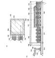
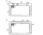
特に画素領域及び駆動回路領域を同一基板上に設ける表示装置においては、画素領域及び駆動回路領域に設けられる薄膜トランジスタには、それぞれ用いられる用途によって要求される電気的特性や機能が様々に異なっている。よって、それぞれの必要とされる機能や電気特性を有する薄膜トランジスタを作製する必要がある。 In particular, in a display device in which a pixel region and a drive circuit region are provided over the same substrate, the thin film transistors provided in the pixel region and the drive circuit region have different electrical characteristics and functions required depending on the intended use. . Therefore, it is necessary to manufacture a thin film transistor having each required function and electrical characteristics.
本発明は、駆動回路領域においては、高速動作が可能で駆動電圧の低い薄膜トランジスタを、一方、画素領域においては、電圧に対して高耐圧で信頼性の高い薄膜トランジスタを有する表示装置を提供することを目的とする。従って、低消費電力かつ高信頼性を付与された表示装置を提供することを目的とする。 The present invention provides a display device having a thin film transistor that can operate at high speed and has a low driving voltage in the driver circuit region, and has a thin film transistor that has a high withstand voltage and high reliability with respect to the voltage in the pixel region. Objective. Therefore, an object is to provide a display device with low power consumption and high reliability.
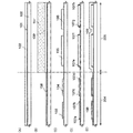
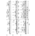
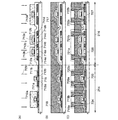
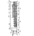
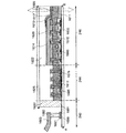
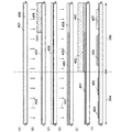
本発明の表示装置は、画素領域及び駆動回路領域にそれぞれ薄膜トランジスタを有しており、駆動回路領域に設けられた薄膜トランジスタの半導体層の膜厚は、画素領域に設けられた薄膜トランジスタの半導体層の膜厚より薄いことを特徴とする。従って、ゲート絶縁層においても、駆動回路領域に設けられた薄膜トランジスタは、画素領域に設けられた薄膜トランジスタより膜厚が薄い方が好ましい。 The display device of the present invention includes a thin film transistor in each of the pixel region and the driver circuit region, and the thickness of the semiconductor layer of the thin film transistor provided in the driver circuit region is the same as that of the semiconductor layer of the thin film transistor provided in the pixel region. It is characterized by being thinner than the thickness. Therefore, also in the gate insulating layer, the thin film transistor provided in the driver circuit region is preferably thinner than the thin film transistor provided in the pixel region.
本発明の表示装置において、駆動回路領域に設けられる薄膜トランジスタの半導体層の膜厚は、5nm以上30nm以下、より好ましくは10nm以上20nm以下とすればよい。一方、画素領域に設けられる薄膜トランジスタの半導体層の膜厚は、25nm以上100nm以下、より好ましくは50nm以上60nm以下とすればよい。 In the display device of the present invention, the thickness of the semiconductor layer of the thin film transistor provided in the driver circuit region may be 5 nm to 30 nm, more preferably 10 nm to 20 nm. On the other hand, the thickness of the semiconductor layer of the thin film transistor provided in the pixel region may be 25 nm to 100 nm, more preferably 50 nm to 60 nm.
本発明の表示装置において、駆動回路領域に設けられる薄膜トランジスタのゲート絶縁層の膜厚は、1nm以上10nm以下、より好ましくは5nm程度とすればよい。一方、画素領域に設けられる薄膜トランジスタのゲート絶縁層の膜厚は、50nm以上150nm以下、より好ましくは60nm以上80nm以下とすればよい。 In the display device of the present invention, the thickness of the gate insulating layer of the thin film transistor provided in the driver circuit region may be 1 nm to 10 nm, more preferably about 5 nm. On the other hand, the thickness of the gate insulating layer of the thin film transistor provided in the pixel region may be 50 to 150 nm, more preferably 60 to 80 nm.
半導体層は結晶性半導体層を用いればよく、非晶質半導体層を熱や光で結晶化した結晶性半導体層でも、単結晶基板でもよい。また、半導体層としては珪素(シリコン)を用いることができる。 The semiconductor layer may be a crystalline semiconductor layer, and may be a crystalline semiconductor layer obtained by crystallizing an amorphous semiconductor layer with heat or light, or a single crystal substrate. In addition, silicon (silicon) can be used for the semiconductor layer.
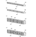
駆動回路領域に設けられた薄膜トランジスタは、半導体層(又は、さらにゲート絶縁層も)を薄膜化することによって、微細化できるため駆動回路領域の面積の縮小が可能となり狭額縁化が達成でき、かつより高速動作が可能となり、駆動電圧も低くすることができる。従って、表示装置を低消費電力とすることができる。 The thin film transistor provided in the driver circuit region can be miniaturized by reducing the thickness of the semiconductor layer (or gate insulating layer), so that the area of the driver circuit region can be reduced, and a narrow frame can be achieved. Higher speed operation is possible, and the drive voltage can be lowered. Accordingly, the display device can have low power consumption.
一方、画素領域に設けられた薄膜トランジスタは、半導体層(又は、さらにゲート絶縁層も)を駆動回路領域と比べ厚く保つことによって、電圧に対して耐圧性が高く、高信頼性とすることができる。 On the other hand, a thin film transistor provided in a pixel region has high withstand voltage against voltage and high reliability by keeping a semiconductor layer (or a gate insulating layer) thicker than a driver circuit region. .
従って、本発明の表示装置は、低消費電力かつ高信頼性が付与された表示装置とすることができる。 Therefore, the display device of the present invention can be a display device with low power consumption and high reliability.
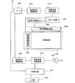
本発明は表示機能を有する装置である表示装置に用いることができ、本発明を用いる表示装置には、エレクトロルミネセンス(以下「EL」ともいう。)と呼ばれる発光を発現する有機物、無機物、若しくは有機物と無機物の混合物を含む層を、電極間に介在させた発光素子とTFTとが接続された発光表示装置や、液晶材料を有する液晶素子を表示素子として用いる液晶表示装置などがある。本発明において、表示装置とは、表示素子(液晶素子や発光素子など)を有する装置のことを言う。なお、基板上に液晶素子やEL素子などの表示素子を含む複数の画素やそれらの画素を駆動させる周辺駆動回路が形成された表示パネル本体のことでもよい。さらに、フレキシブルプリントサーキット(FPC)やプリント配線基盤(PWB)が取り付けられたもの(ICや抵抗素子や容量素子やインダクタやトランジスタなど)も含んでもよい。さらに、偏光板や位相差板などの光学シートを含んでいても良い。さらに、バックライト(導光板やプリズムシートや拡散シートや反射シートや光源(LEDや冷陰極管など)を含んでいても良い)を含んでいても良い。 The present invention can be used for a display device that is a device having a display function. The display device using the present invention includes an organic substance, an inorganic substance, or an organic substance that emits light called electroluminescence (hereinafter also referred to as “EL”). There are a light-emitting display device in which a light-emitting element in which a layer containing a mixture of an organic substance and an inorganic substance is interposed between electrodes and a TFT are connected, and a liquid crystal display device in which a liquid crystal element having a liquid crystal material is used as a display element. In the present invention, a display device refers to a device having a display element (such as a liquid crystal element or a light emitting element). Note that a display panel body in which a plurality of pixels including a display element such as a liquid crystal element or an EL element and a peripheral driver circuit for driving these pixels are formed over a substrate may be used. Furthermore, a device to which a flexible printed circuit (FPC) or a printed wiring board (PWB) is attached (such as an IC, a resistor, a capacitor, an inductor, or a transistor) may also be included. Furthermore, an optical sheet such as a polarizing plate or a retardation plate may be included. Furthermore, a backlight (which may include a light guide plate, a prism sheet, a diffusion sheet, a reflection sheet, or a light source (such as an LED or a cold cathode tube)) may be included.
なお、表示素子や表示装置は、様々な形態及び様々な素子を用いることができる。例えば、EL素子(有機EL素子、無機EL素子又は有機物及び無機物を含むEL素子)、電子放出素子、液晶素子、電子インク、グレーティングライトバルブ(GLV)、プラズマディスプレイ(PDP)、デジタルマイクロミラーデバイス(DMD)、圧電セラミックディスプレイ、カーボンナノチューブ、など、電気磁気的作用によりコントラストが変化する表示媒体を適用することができる。なお、EL素子を用いた表示装置としてはELディスプレイ、電子放出素子を用いた表示装置としてはフィールドエミッションディスプレイ(FED)やSED方式平面型ディスプレイ(SED:Surface−conduction Electron−emitter Disply)など、液晶素子を用いた表示装置としては液晶ディスプレイ、透過型液晶ディスプレイ、半透過型液晶ディスプレイ、反射型液晶ディスプレイ、電子インクを用いた表示装置としては電子ペーパーがある。 Note that various forms and various elements can be used for the display element and the display device. For example, EL elements (organic EL elements, inorganic EL elements or EL elements including organic and inorganic substances), electron-emitting elements, liquid crystal elements, electronic ink, grating light valves (GLV), plasma displays (PDP), digital micromirror devices ( DMD), piezoelectric ceramic displays, carbon nanotubes, and the like, which can be applied to display media whose contrast is changed by an electromagnetic action. Note that a display device using an EL element is an EL display, and a display device using an electron-emitting device is a liquid crystal display such as a field emission display (FED) or a SED type flat display (SED: Surface-conduction Electron-Emitter Display). A display device using the element includes a liquid crystal display, a transmissive liquid crystal display, a transflective liquid crystal display, a reflective liquid crystal display, and a display device using electronic ink includes electronic paper.
本発明の表示装置の一形態は、絶縁表面を有する基板上に設けられた画素領域及び駆動回路領域を有し、画素領域に、第1のゲート電極層、第1のソース領域及び第1のドレイン領域を含む第1の半導体層、並びに第1のゲート絶縁層を含む第1の薄膜トランジスタと、駆動回路領域に、第2のゲート電極層、第2のソース領域及び第2のドレイン領域を含み第1の半導体層より膜厚の薄い第2の半導体層、並びに第2のゲート絶縁層を含む第2の薄膜トランジスタとを有する。 One embodiment of a display device of the present invention includes a pixel region and a driver circuit region which are provided over a substrate having an insulating surface, and the pixel region includes a first gate electrode layer, a first source region, and a first source region. A first semiconductor layer including a drain region; a first thin film transistor including a first gate insulating layer; and a driver circuit region including a second gate electrode layer, a second source region, and a second drain region. A second semiconductor layer having a thickness smaller than that of the first semiconductor layer; and a second thin film transistor including a second gate insulating layer.
本発明の表示装置の一形態は、絶縁表面を有する基板上に設けられた画素領域及び駆動回路領域を有し、画素領域に、第1のゲート電極層、第1のソース領域及び第1のドレイン領域を含む第1の半導体層、並びに第1のゲート絶縁層を含む第1の薄膜トランジスタと、駆動回路領域に、第2のゲート電極層、第2のソース領域及び第2のドレイン領域を含み第1の半導体層より膜厚の薄い第2の半導体層、並びに第1のゲート絶縁層より膜厚の薄い第2のゲート絶縁層を含む第2の薄膜トランジスタとを有する。 One embodiment of a display device of the present invention includes a pixel region and a driver circuit region which are provided over a substrate having an insulating surface, and the pixel region includes a first gate electrode layer, a first source region, and a first source region. A first semiconductor layer including a drain region; a first thin film transistor including a first gate insulating layer; and a driver circuit region including a second gate electrode layer, a second source region, and a second drain region. A second semiconductor layer including a second semiconductor layer having a thickness smaller than that of the first semiconductor layer and a second gate insulating layer having a thickness smaller than that of the first gate insulating layer.
本発明の表示装置の一形態は、絶縁表面を有する基板上に設けられた画素領域及び駆動回路領域を有し、画素領域に、第1のゲート電極層、第1のソース領域及び第1のドレイン領域を含む第1の半導体層、並びに第1のゲート絶縁層を含む第1の薄膜トランジスタと、駆動回路領域に、第2のゲート電極層、第2のソース領域及び第2のドレイン領域を含み第1の半導体層より膜厚の薄い第2の半導体層、並びに第2のゲート絶縁層を含む第2の薄膜トランジスタとを有し、第1のゲート電極層及び第2のゲート電極層の側面にサイドウォール構造の絶縁層が設けられている。 One embodiment of a display device of the present invention includes a pixel region and a driver circuit region which are provided over a substrate having an insulating surface, and the pixel region includes a first gate electrode layer, a first source region, and a first source region. A first semiconductor layer including a drain region; a first thin film transistor including a first gate insulating layer; and a driver circuit region including a second gate electrode layer, a second source region, and a second drain region. A second semiconductor layer having a thickness smaller than that of the first semiconductor layer, and a second thin film transistor including a second gate insulating layer, and provided on side surfaces of the first gate electrode layer and the second gate electrode layer An insulating layer having a sidewall structure is provided.
本発明の表示装置の一形態は、画素領域に、絶縁表面を有する基板上に設けられた画素領域及び駆動回路領域を有し、第1のゲート電極層、第1のソース領域及び第1のドレイン領域を含む第1の半導体層、並びに第1のゲート絶縁層を含む第1の薄膜トランジスタと、駆動回路領域に、第2のゲート電極層、第2のソース領域及び第2のドレイン領域を含み第1の半導体層より膜厚の薄い第2の半導体層、並びに第1のゲート絶縁層より膜厚の薄い第2のゲート絶縁層を含む第2の薄膜トランジスタとを有し、第1のゲート電極層及び第2のゲート電極層の側面にサイドウォール構造の絶縁層が設けられている。 One embodiment of a display device of the present invention includes a pixel region and a driver circuit region which are provided over a substrate having an insulating surface in a pixel region, and includes a first gate electrode layer, a first source region, and a first source region. A first semiconductor layer including a drain region; a first thin film transistor including a first gate insulating layer; and a driver circuit region including a second gate electrode layer, a second source region, and a second drain region. And a second thin film transistor including a second semiconductor layer having a thickness smaller than that of the first semiconductor layer and a second gate insulating layer having a thickness smaller than that of the first gate insulating layer. An insulating layer having a sidewall structure is provided on side surfaces of the layer and the second gate electrode layer.
本発明の表示装置の一形態は、絶縁表面を有する基板上に設けられた画素領域及び駆動回路領域を有し、画素領域に、第1のゲート電極層、第1のソース領域及び第1のドレイン領域を含む第1の半導体層、並びに第1のゲート絶縁層を含む第1の薄膜トランジスタと、駆動回路領域に、第2のゲート電極層、第2のソース領域及び第2のドレイン領域を含み第1の半導体層より膜厚の薄い第2の半導体層、並びに第2のゲート絶縁層を含む第2の薄膜トランジスタとを有し、第1のゲート電極層及び第2のゲート電極層の側面にサイドウォール構造の絶縁層と、第1のソース領域、第1のドレイン領域、第2のソース領域、及び第2のドレイン領域の表面にシリサイドとが設けられている。 One embodiment of a display device of the present invention includes a pixel region and a driver circuit region which are provided over a substrate having an insulating surface, and the pixel region includes a first gate electrode layer, a first source region, and a first source region. A first semiconductor layer including a drain region; a first thin film transistor including a first gate insulating layer; and a driver circuit region including a second gate electrode layer, a second source region, and a second drain region. A second semiconductor layer having a thickness smaller than that of the first semiconductor layer, and a second thin film transistor including a second gate insulating layer, and provided on side surfaces of the first gate electrode layer and the second gate electrode layer An insulating layer having a sidewall structure and silicide are provided on surfaces of the first source region, the first drain region, the second source region, and the second drain region.
本発明の表示装置の一形態は、絶縁表面を有する基板上に設けられた画素領域及び駆動回路領域を有し、画素領域に、第1のゲート電極層、第1のソース領域及び第1のドレイン領域を含む第1の半導体層、並びに第1のゲート絶縁層を含む第1の薄膜トランジスタと、駆動回路領域に、第2のゲート電極層、第2のソース領域及び第2のドレイン領域を含み第1の半導体層より膜厚の薄い第2の半導体層、並びに第1のゲート絶縁層より膜厚の薄い第2のゲート絶縁層を含む第2の薄膜トランジスタとを有し、第1のゲート電極層及び第2のゲート電極層の側面にサイドウォール構造の絶縁層と、第1のソース領域、第1のドレイン領域、第2のソース領域、及び第2のドレイン領域の表面にシリサイドとが設けられている。 One embodiment of a display device of the present invention includes a pixel region and a driver circuit region which are provided over a substrate having an insulating surface, and the pixel region includes a first gate electrode layer, a first source region, and a first source region. A first semiconductor layer including a drain region; a first thin film transistor including a first gate insulating layer; and a driver circuit region including a second gate electrode layer, a second source region, and a second drain region. And a second thin film transistor including a second semiconductor layer having a thickness smaller than that of the first semiconductor layer and a second gate insulating layer having a thickness smaller than that of the first gate insulating layer. An insulating layer having a sidewall structure is provided on the side surfaces of the layer and the second gate electrode layer, and silicide is provided on the surfaces of the first source region, the first drain region, the second source region, and the second drain region. It has been.
上記構成において、第1の半導体層及び第2の半導体層は側面にサイドウォール構造の絶縁層をしていてもよい。また、第1の半導体層、及び第2の半導体層のどちらか一方、又は両方は第1のソース領域、第1のドレイン領域、及びソース領域及びドレイン領域より低濃度の一導電型を有する不純物領域を含んでもよい。 In the above structure, the first semiconductor layer and the second semiconductor layer may have side wall insulating layers on the side surfaces. In addition, one or both of the first semiconductor layer and the second semiconductor layer is an impurity having one conductivity type having a lower concentration than the first source region, the first drain region, and the source region and the drain region. An area may be included.
本発明の表示装置は、画素領域及び駆動回路領域にそれぞれ薄膜トランジスタを有しており、駆動回路領域に設けられた薄膜トランジスタの半導体層の膜厚は、画素領域に設けられた薄膜トランジスタの半導体層の膜厚より薄い。 The display device of the present invention includes a thin film transistor in each of the pixel region and the driver circuit region, and the thickness of the semiconductor layer of the thin film transistor provided in the driver circuit region is the same as that of the semiconductor layer of the thin film transistor provided in the pixel region. Thinner than thickness.
駆動回路領域に設けられた薄膜トランジスタは、半導体層(又は、さらにゲート絶縁層も)を薄膜化することによって、微細化できるため駆動回路領域の面積の縮小が可能となり狭額縁化が達成でき、かつより高速動作が可能となり、駆動電圧も低くすることができる。半導体層の薄膜化は、チャネル形成領域の全域を空乏層化するように作用する。従って、表示装置を低消費電力とすることができる。 The thin film transistor provided in the driver circuit region can be miniaturized by reducing the thickness of the semiconductor layer (or gate insulating layer), so that the area of the driver circuit region can be reduced, and a narrow frame can be achieved. Higher speed operation is possible, and the drive voltage can be lowered. The thinning of the semiconductor layer acts to deplete the entire channel formation region. Accordingly, the display device can have low power consumption.
一方、画素領域に設けられた薄膜トランジスタは、半導体層(又は、さらにゲート絶縁層も)を駆動回路領域と比べ厚く保つことによって、電圧に対する耐圧性が高く、高信頼性とすることができる。 On the other hand, the thin film transistor provided in the pixel region has high withstand voltage against voltage and high reliability by keeping the semiconductor layer (or the gate insulating layer) thicker than the driver circuit region.
従って、本発明の表示装置は、低消費電力かつ高信頼性が付与された表示装置とすることができる。 Therefore, the display device of the present invention can be a display device with low power consumption and high reliability.
本発明の実施の形態について、図面を用いて詳細に説明する。但し、本発明は以下の説明に限定されず、本発明の趣旨及びその範囲から逸脱することなくその形態及び詳細を様々に変更し得ることは当業者であれば容易に理解される。従って、本発明は以下に示す実施の形態の記載内容に限定して解釈されるものではない。なお、以下に説明する本発明の構成において、同一部分又は同様な機能を有する部分には同一の符号を異なる図面間で共通して用い、その繰り返しの説明は省略する。 Embodiments of the present invention will be described in detail with reference to the drawings. However, the present invention is not limited to the following description, and it is easily understood by those skilled in the art that modes and details can be variously changed without departing from the spirit and scope of the present invention. Therefore, the present invention should not be construed as being limited to the description of the embodiments below. Note that in structures of the present invention described below, the same portions or portions having similar functions are denoted by the same reference numerals in different drawings, and description thereof is not repeated.
(実施の形態1)
本実施の形態では、低消費電力で、かつ高信頼性を付与することを目的とした表示装置、及び表示装置の作製方法を、図1乃至図4、図15を用いて詳細に説明する。
(Embodiment 1)
In this embodiment, a display device with low power consumption and high reliability and a method for manufacturing the display device will be described in detail with reference to FIGS.
図15(A)は本発明に係る表示パネルの構成を示す上面図であり、絶縁表面を有する基板3700上に画素3705をマトリクス上に配列させた画素領域3701、信号線入力端子3704が形成されている。画素数は種々の規格に従って設ければ良く、XGAであれば1024×768×3(RGB)、UXGAであれば1600×1200×3(RGB)、フルスペックハイビジョンに対応させるのであれば1920×1080×3(RGB)とすれば良い。
FIG. 15A is a top view illustrating a structure of a display panel according to the present invention, in which a
画素3705は、走査線駆動回路3702から延在する走査線と、信号線入力端子3704から延在する信号線とが交差することで、マトリクス状に配設される。画素3705のそれぞれには、スイッチング素子とそれに接続する画素電極層が備えられている。スイッチング素子の代表的な一例はTFTであり、TFTのゲート電極層側が走査線と、ソース若しくはドレイン側が信号線と接続されることにより、個々の画素を外部から入力する信号によって独立して制御可能としている。
The pixels 3705 are arranged in a matrix by intersecting scanning lines extending from the scanning
TFTは、その主要な構成要素として、半導体層、ゲート絶縁層及びゲート電極層が挙げられ、半導体層に形成されるソース領域及びドレイン領域に接続する配線層がそれに付随する。構造的には基板側から半導体層、ゲート絶縁層及びゲート電極層を配設したトップゲート型を用いればよい。 A TFT includes a semiconductor layer, a gate insulating layer, and a gate electrode layer as main components, and a wiring layer connected to a source region and a drain region formed in the semiconductor layer is attached to the TFT. Structurally, a top gate type in which a semiconductor layer, a gate insulating layer, and a gate electrode layer are provided from the substrate side may be used.
図15(A)は、信号線へ入力する信号を、外付けの駆動回路により制御する表示パネルの構成を示している。外付けの駆動回路の実装方法としては、COG(Chip on Glass)方式によりドライバICを基板3700上に実装しても良いし、TAB(Tape Automated Bonding)方式を用いて実装してもよい。ドライバICは単結晶半導体基板に形成されたものでも良いし、ガラス基板上にTFTで回路を形成したものであっても良い。
FIG. 15A illustrates a structure of a display panel in which a signal input to a signal line is controlled by an external driver circuit. As a mounting method of the external driving circuit, the driver IC may be mounted on the
また、図15(B)のように、画素領域4701、走査線駆動回路4702、4703と、信号線駆動回路4704を基板4700上に一体形成することもできる。
15B, the
本発明においては、画素領域に設けられる薄膜トランジスタと、駆動回路領域に設けられる薄膜トランジスタとをそれぞれ必要とされる機能を有するような構造に作り分ける。駆動回路領域に設けられる薄膜トランジスタは、高速駆動が要求されるため、半導体層(又は、さらにゲート絶縁層も)を、より薄膜化し、一方、画素領域に設けられる薄膜トランジスタは、高電圧に対する耐性など高い信頼性が要求されるため、駆動回路領域の薄膜トランジスタより半導体層(又は、さらにゲート絶縁層も)を厚膜化する。よって発明の表示装置は、駆動回路領域に設けられる薄膜トランジスタと、画素領域に設けられる薄膜トランジスタとの半導体層(又は、さらにゲート絶縁層も)の膜厚が異なり、駆動回路領域の薄膜トランジスタの方が画素領域のトランジスタより半導体層(又は、さらにゲート絶縁層も)の膜厚が薄い。 In the present invention, the thin film transistor provided in the pixel region and the thin film transistor provided in the driver circuit region are separately formed in a structure having a required function. Since the thin film transistor provided in the driver circuit region is required to be driven at high speed, the semiconductor layer (or the gate insulating layer) is made thinner. On the other hand, the thin film transistor provided in the pixel region has high resistance to high voltage. Since reliability is required, the semiconductor layer (or the gate insulating layer) is made thicker than the thin film transistor in the driver circuit region. Therefore, in the display device of the invention, the thickness of the semiconductor layer (or the gate insulating layer) of the thin film transistor provided in the driver circuit region is different from that of the thin film transistor provided in the pixel region. The thickness of the semiconductor layer (or the gate insulating layer) is smaller than that of the transistor in the region.
図15(A)においては、走査線駆動回路3702に含まれる薄膜トランジスタの半導体層(又は、さらにゲート絶縁層も)を、画素領域3701に含まれる薄膜トランジスタの半導体層(又は、さらにゲート絶縁層も)より薄膜化して形成する。
In FIG. 15A, the semiconductor layer (or gate insulating layer) of the thin film transistor included in the scan
図15(B)においては、走査線駆動回路4702、4703、及び信号線駆動回路4704に含まれる薄膜トランジスタの半導体層(又は、さらにゲート絶縁層も)を、画素領域3701に含まれる薄膜トランジスタの半導体層(又は、さらにゲート絶縁層も)より薄膜化して形成する。薄膜トランジスタの半導体層の薄膜化は、走査線駆動回路4702、4703と、及び信号線駆動回路4704両方で行っても良いし、走査線駆動回路4702、4703と、又は信号線駆動回路4704のどちらか一方でもよい。駆動回路領域である走査線駆動回路4702、4703と、及び信号線駆動回路4704に含まれる複数の薄膜トランジスタにおいて、半導体層(又は、さらにゲート絶縁層も)とが薄膜化(画素領域より)した薄膜トランジスタが含まれていればよい。
In FIG. 15B, a thin film transistor semiconductor layer (or a gate insulating layer) included in the scan
駆動回路領域の薄膜トランジスタにおいて、ゲート電極のソースとドレイン間の距離として表されるチャネル長の長さを短くしてトランジスタのチャネルを流れるキャリアの走行距離を短くすることによって、高速化を行うことができる。 In the thin film transistor in the driver circuit region, the channel length expressed as the distance between the source and drain of the gate electrode can be shortened to shorten the travel distance of carriers flowing through the transistor channel, thereby increasing the speed. it can.
しかし、薄膜トランジスタの高性能化のため、チャネル長を短くするとしきい値電圧の変化、弱反転状態におけるソースドレイン間のリーク電流の増加など、いわゆる短チャネル効果と呼ばれる現象が顕在化する。 However, in order to improve the performance of thin film transistors, when the channel length is shortened, a so-called short channel effect phenomenon such as a change in threshold voltage and an increase in leakage current between the source and drain in a weak inversion state becomes apparent.
半導体層の薄膜化は、チャネル形成領域の全域を空乏層化するように作用し、短チャネル効果を抑制することができる。また、薄膜トランジスタのしきい値電圧を小さくすることができる。それにより、駆動回路領域に設けられた薄膜トランジスタにおいて、微細化と高性能化を実現することができる。よって、表示装置の低電圧駆動が可能となり低消費電力化を実現することができる。また、薄膜トランジスタは、半導体層(又は、さらにゲート絶縁層も)を薄膜化することによって、微細化できるため、駆動回路領域の面積の縮小が可能となり、表示装置の狭額縁化が達成できる。従って表示装置をより小型化することができる。 The thinning of the semiconductor layer acts to make the entire channel formation region a depletion layer, and can suppress the short channel effect. In addition, the threshold voltage of the thin film transistor can be reduced. Accordingly, miniaturization and high performance can be realized in the thin film transistor provided in the driver circuit region. Accordingly, the display device can be driven at a low voltage, and low power consumption can be realized. In addition, since the thin film transistor can be miniaturized by reducing the thickness of the semiconductor layer (or the gate insulating layer), the area of the driver circuit region can be reduced, and a narrow frame of the display device can be achieved. Therefore, the display device can be further downsized.
絶縁表面を有する基板100の上に下地膜として、下地膜101を形成する。本実施の形態では、下地膜101として積層構造を用い、窒化酸化珪素膜を10〜200nm(好ましくは50〜150nm)形成し、酸化窒化珪素膜を50〜200nm(好ましくは100〜150nm)形成する。本実施の形態では、プラズマCVD法を用いて下地膜101を形成する。下地膜は、単層でも2層、3層といった積層構造でもよい。
A
下地膜の材料は、酸化珪素、窒化珪素、酸化窒化珪素、窒化酸化珪素などの無機材料、アクリル酸、メタクリル酸及びこれらの誘導体、又はポリイミド(polyimide)、芳香族ポリアミド、ポリベンゾイミダゾール(polybenzimidazole)などの耐熱性高分子、又はシロキサン樹脂を用いてもよい。また、ポリビニルアルコール、ポリビニルブチラールなどのビニル樹脂、エポキシ樹脂、フェノール樹脂、ノボラック樹脂、アクリル樹脂、メラミン樹脂、ウレタン樹脂等の樹脂材料を用いてもよい。また、ベンゾシクロブテン、パリレン、フッ化アリレンエーテル、ポリイミドなどの有機材料、水溶性ホモポリマーと水溶性共重合体を含む組成物材料等を用いてもよい。また、オキサゾール樹脂を用いることもでき、例えば光硬化型ポリベンゾオキサゾールなどを用いることができる。 The material of the base film is an inorganic material such as silicon oxide, silicon nitride, silicon oxynitride, and silicon nitride oxide, acrylic acid, methacrylic acid and derivatives thereof, or polyimide, aromatic polyamide, polybenzimidazole. A heat resistant polymer such as siloxane resin may be used. Moreover, resin materials such as vinyl resins such as polyvinyl alcohol and polyvinyl butyral, epoxy resins, phenol resins, novolac resins, acrylic resins, melamine resins, and urethane resins may be used. Further, an organic material such as benzocyclobutene, parylene, fluorinated arylene ether, polyimide, a composition material containing a water-soluble homopolymer and a water-soluble copolymer, or the like may be used. Moreover, an oxazole resin can also be used, for example, photocurable polybenzoxazole or the like can be used.
下地膜は、スパッタリング法、PVD法(Physical Vapor Deposition)、減圧CVD法(LPCVD法)、またはプラズマCVD法等のCVD法(Chemical Vapor Deposition)などを用いて形成することができる。また、液滴吐出法や、印刷法(スクリーン印刷やオフセット印刷などパターンが形成される方法)、スピンコート法などの塗布法、ディッピング法、ディスペンサ法などを用いることもできる。 The base film can be formed by a sputtering method, a PVD method (Physical Vapor Deposition), a low pressure CVD method (LPCVD method), a CVD method such as a plasma CVD method (Chemical Vapor Deposition), or the like. Further, a droplet discharge method, a printing method (a method for forming a pattern such as screen printing or offset printing), a coating method such as a spin coating method, a dipping method, a dispenser method, or the like can also be used.
基板100としてはガラス基板、石英基板を用いることができる。また、本実施の形態の処理温度に耐えうる耐熱性を有するプラスチック基板を用いてもよいし、フィルムのような可撓性基板を用いても良い。プラスチック基板としてはPET(ポリエチレンテレフタレート)、PEN(ポリエチレンナフタレート)、PES(ポリエーテルサルフォン)からなる基板、可撓性基板としてはアクリル等の合成樹脂を用いることができる。本実施の形態で作製する表示装置は、基板100を通過させて発光素子よりの光を取り出す構成であるので、基板100は透光性を有する必要がある。
As the
次いで、下地膜上に半導体膜を形成する。半導体膜は25〜200nm(好ましくは30〜150nm)の厚さで手段(スパッタ法、LPCVD法、またはプラズマCVD法等)により成膜すればよい。本発明では、非晶質半導体膜を、レーザ結晶化し、結晶性半導体膜とするものを用いるのが好ましい。 Next, a semiconductor film is formed over the base film. The semiconductor film may be formed by means (a sputtering method, an LPCVD method, a plasma CVD method, or the like) with a thickness of 25 to 200 nm (preferably 30 to 150 nm). In the present invention, it is preferable to use a crystalline semiconductor film obtained by crystallizing an amorphous semiconductor film by laser.
半導体膜を形成する材料は、シランやゲルマンに代表される半導体材料ガスを用いて気相成長法やスパッタリング法で作製される非晶質半導体(以下「アモルファス半導体:AS」ともいう。)を光エネルギーや熱エネルギーを利用して結晶化させた多結晶半導体、或いは単結晶半導体などを用いることができる。 As a material for forming the semiconductor film, an amorphous semiconductor (hereinafter, also referred to as “amorphous semiconductor: AS”) manufactured by a vapor deposition method or a sputtering method using a semiconductor material gas typified by silane or germane is used. A polycrystalline semiconductor crystallized using energy or heat energy, a single crystal semiconductor, or the like can be used.
非晶質半導体としては、代表的には水素化アモルファスシリコン、結晶性半導体としては代表的にはポリシリコンなどがあげられる。ポリシリコン(多結晶シリコン)には、800℃以上のプロセス温度を経て形成されるポリシリコンを主材料として用いた所謂高温ポリシリコンや、600℃以下のプロセス温度で形成されるポリシリコンを主材料として用いた所謂低温ポリシリコン、また結晶化を促進する元素などを添加し結晶化させたポリシリコンなどを含んでいる。また、このような薄膜プロセスに換えて、絶縁表面に単結晶半導体層を設けたSOI基板を用いても良い。SOI基板は、SIMOX(Separation by IMplanted Oxygen)法や、Smart−Cut法を用いて形成することができる。SIMOX法は、単結晶シリコン基板に酸素イオンを注入し、所定の深さに酸素含有層を形成した後、熱処理を行い、表面から一定の深さで埋込絶縁層を形成し、埋込絶縁層の上に単結晶シリコン層を形成する方法である。また、Smart−Cut法は、酸化された単結晶シリコン基板に水素イオン注入を行い、所望の深さに相当する所に水素含有層を形成し、他の支持基板(表面に貼り合わせ用の酸化シリコン膜を有する単結晶シリコン基板など)と貼り合わせる、加熱処理を行うことにより水素含有層にて単結晶シリコン基板を分断し、支持基板上に酸化シリコン膜と単結晶シリコン層との積層を形成する方法である。 A typical example of an amorphous semiconductor is hydrogenated amorphous silicon, and a typical example of a crystalline semiconductor is polysilicon. Polysilicon (polycrystalline silicon) is mainly made of so-called high-temperature polysilicon using polysilicon formed through a process temperature of 800 ° C. or more as a main material, or polysilicon formed at a process temperature of 600 ° C. or less. And so-called low-temperature polysilicon, and polysilicon crystallized by adding an element that promotes crystallization. Further, instead of such a thin film process, an SOI substrate in which a single crystal semiconductor layer is provided over an insulating surface may be used. The SOI substrate can be formed using a SIMOX (Separation by IM planted Oxygen) method or a Smart-Cut method. In the SIMOX method, oxygen ions are implanted into a single crystal silicon substrate, an oxygen-containing layer is formed at a predetermined depth, and then heat treatment is performed to form a buried insulating layer at a certain depth from the surface. In this method, a single crystal silicon layer is formed on the layer. In the Smart-Cut method, hydrogen ions are implanted into an oxidized single crystal silicon substrate, a hydrogen-containing layer is formed at a position corresponding to a desired depth, and another supporting substrate (an oxide for bonding to the surface) is formed. A single-crystal silicon substrate having a silicon film is bonded to the hydrogen-containing layer by heat treatment, and a stack of the silicon oxide film and the single-crystal silicon layer is formed on the supporting substrate. It is a method to do.
結晶性半導体層の作製方法は、種々の方法(レーザ結晶化法、熱結晶化法、またはニッケルなどの結晶化を助長する元素を用いた熱結晶化法等)を用いれば良い。また微結晶半導体をレーザ照射して結晶化し、結晶性を高めることもできる。結晶化を助長する元素を導入しない場合は、非晶質半導体層にレーザ光を照射する前に、窒素雰囲気下500℃で1時間加熱することによって非晶質半導体層の含有水素濃度を1×10²⁰atoms/cm3以下にまで放出させる。これは水素を多く含んだ非晶質半導体層にレーザ光を照射すると非晶質半導体層が破壊されてしまうからである。結晶化のための加熱処理は、加熱炉、レーザ照射、若しくはランプから発する光の照射(ランプアニールともいう)などを用いることができる。加熱方法としてGRTA(Gas Rapid Thermal Anneal)法、LRTA(Lamp Rapid Thermal Anneal)法等のRTA法がある。GRTAとは高温のガスを用いて加熱処理を行う方法であり、LRTAとはランプ光により加熱処理を行う方法である。 As a method for manufacturing the crystalline semiconductor layer, various methods (such as a laser crystallization method, a thermal crystallization method, or a thermal crystallization method using an element that promotes crystallization such as nickel) may be used. Further, the crystallinity can be increased by crystallizing a microcrystalline semiconductor by laser irradiation. In the case where an element for promoting crystallization is not introduced, the concentration of hydrogen contained in the amorphous semiconductor layer is set to 1 × by heating at 500 ° C. for 1 hour in a nitrogen atmosphere before irradiating the amorphous semiconductor layer with laser light. Release to 10 20 atoms / cm 3 or less. This is because when an amorphous semiconductor layer containing a large amount of hydrogen is irradiated with laser light, the amorphous semiconductor layer is destroyed. As the heat treatment for crystallization, a heating furnace, laser irradiation, irradiation with light emitted from a lamp (also referred to as lamp annealing), or the like can be used. There are RTA methods such as a GRTA (Gas Rapid Thermal Anneal) method and an LRTA (Lamp Rapid Thermal Anneal) method as heating methods. GRTA is a method for performing heat treatment using a high-temperature gas, and LRTA is a method for performing heat treatment with lamp light.
また、非晶質半導体層を結晶化し、結晶性半導体層を形成する結晶化工程で、非晶質半導体層に結晶化を促進する元素(触媒元素、金属元素とも示す)を添加し、熱処理(550℃〜750℃で3分〜24時間)により結晶化を行ってもよい。結晶化を助長する元素としては、鉄(Fe)、ニッケル(Ni)、コバルト(Co)、ルテニウム(Ru)、ロジウム(Rh)、パラジウム(Pd)、オスニウム(Os)、イリジウム(Ir)、白金(Pt)、銅(Cu)及び金(Au)から選ばれた一種又は複数種類を用いることができる。 Further, in the crystallization step of crystallizing the amorphous semiconductor layer to form the crystalline semiconductor layer, an element for promoting crystallization (also referred to as a catalyst element or a metal element) is added to the amorphous semiconductor layer, and heat treatment ( Crystallization may be carried out at 550 ° C. to 750 ° C. for 3 minutes to 24 hours. Elements that promote crystallization include iron (Fe), nickel (Ni), cobalt (Co), ruthenium (Ru), rhodium (Rh), palladium (Pd), osmium (Os), iridium (Ir), and platinum. One or more types selected from (Pt), copper (Cu), and gold (Au) can be used.
非晶質半導体層への金属元素の導入の仕方としては、当該金属元素を非晶質半導体層の表面又はその内部に存在させ得る手法であれば特に限定はなく、例えばスパッタ法、CVD法、プラズマ処理法(プラズマCVD法も含む)、吸着法、金属塩の溶液を塗布する方法を使用することができる。このうち溶液を用いる方法は簡便であり、金属元素の濃度調整が容易であるという点で有用である。また、このとき非晶質半導体層の表面のぬれ性を改善し、非晶質半導体層の表面全体に水溶液を行き渡らせるため、酸素雰囲気中でのUV光の照射、熱酸化法、ヒドロキシラジカルを含むオゾン水又は過酸化水素による処理等により、酸化膜を成膜することが望ましい。 The method of introducing the metal element into the amorphous semiconductor layer is not particularly limited as long as the metal element can be present on the surface of the amorphous semiconductor layer or inside the amorphous semiconductor layer. For example, sputtering, CVD, A plasma treatment method (including a plasma CVD method), an adsorption method, or a method of applying a metal salt solution can be used. Among these, the method using a solution is simple and useful in that the concentration of the metal element can be easily adjusted. At this time, in order to improve the wettability of the surface of the amorphous semiconductor layer and to spread the aqueous solution over the entire surface of the amorphous semiconductor layer, irradiation with UV light in an oxygen atmosphere, thermal oxidation method, hydroxy radical It is desirable to form an oxide film by treatment with ozone water or hydrogen peroxide.
結晶化を促進する元素を結晶性半導体層から除去、又は軽減するため、結晶性半導体層に接して、不純物元素を含む半導体層を形成し、ゲッタリングシンクとして機能させる。不純物元素としては、n型を付与する不純物元素、p型を付与する不純物元素や希ガス元素などを用いることができ、例えばリン(P)、窒素(N)、ヒ素(As)、アンチモン(Sb)、ビスマス(Bi)、ボロン(B)、ヘリウム(He)、ネオン(Ne)、アルゴン(Ar)、Kr(クリプトン)、Xe(キセノン)から選ばれた一種または複数種を用いることができる。結晶化を促進する元素を含む結晶性半導体層に、希ガス元素を含む半導体層を形成し、熱処理(550℃〜750℃で3分〜24時間)を行う。結晶性半導体層中に含まれる結晶化を促進する元素は、希ガス元素を含む半導体層中に移動し、結晶性半導体層中の結晶化を促進する元素は除去、又は軽減される。その後、ゲッタリングシンクとなった希ガス元素を含む半導体層を除去する。 In order to remove or reduce an element that promotes crystallization from the crystalline semiconductor layer, a semiconductor layer containing an impurity element is formed in contact with the crystalline semiconductor layer and functions as a gettering sink. As the impurity element, an impurity element imparting n-type conductivity, an impurity element imparting p-type conductivity, a rare gas element, or the like can be used. For example, phosphorus (P), nitrogen (N), arsenic (As), antimony (Sb ), Bismuth (Bi), boron (B), helium (He), neon (Ne), argon (Ar), Kr (krypton), and Xe (xenon) can be used. A semiconductor layer containing a rare gas element is formed over the crystalline semiconductor layer containing an element that promotes crystallization, and heat treatment (at 550 ° C. to 750 ° C. for 3 minutes to 24 hours) is performed. The element that promotes crystallization contained in the crystalline semiconductor layer moves into the semiconductor layer containing a rare gas element, and the element that promotes crystallization in the crystalline semiconductor layer is removed or reduced. After that, the semiconductor layer containing a rare gas element that has become a gettering sink is removed.
レーザと、半導体層とを相対的に走査することにより、レーザ照射を行うことができる。またレーザ照射において、ビームを精度よく重ね合わせたり、レーザ照射開始位置やレーザ照射終了位置を制御するため、マーカーを形成することもできる。マーカーは非晶質半導体層と同時に、基板上へ形成すればよい。 Laser irradiation can be performed by relatively scanning the laser and the semiconductor layer. In laser irradiation, a marker can be formed in order to superimpose beams with high accuracy and to control the laser irradiation start position and laser irradiation end position. The marker may be formed on the substrate simultaneously with the amorphous semiconductor layer.
レーザ照射を用いる場合、連続発振型のレーザビーム(CW(CW:continuous−wave)レーザビーム)やパルス発振型のレーザビーム(パルスレーザビーム)を用いることができる。ここで用いることができるレーザビームは、Arレーザ、Krレーザ、エキシマレーザなどの気体レーザ、単結晶のYAG、YVO4、フォルステライト(Mg2SiO4)、YAlO3、GdVO4、若しくは多結晶(セラミック)のYAG、Y2O3、YVO4、YAlO3、GdVO4に、ドーパントとしてNd、Yb、Cr、Ti、Ho、Er、Tm、Taのうち1種または複数種添加されているものを媒質とするレーザ、ガラスレーザ、ルビーレーザ、アレキサンドライトレーザ、Ti:サファイアレーザ、銅蒸気レーザまたは金蒸気レーザのうち一種または複数種から発振されるものを用いることができる。このようなレーザビームの基本波、及びこれらの基本波の第2高調波から第4高調波のレーザビームを照射することで、大粒径の結晶を得ることができる。例えば、Nd:YVO4レーザ(基本波1064nm)の第2高調波(532nm)や第3高調波(355nm)を用いることができる。このレーザは、CWで射出することも、パルス発振で射出することも可能である。CWで射出する場合は、レーザのパワー密度を0.01〜100MW/cm2程度(好ましくは0.1〜10MW/cm2)が必要である。そして、走査速度を10〜2000cm/sec程度として照射する。 When laser irradiation is used, a continuous wave laser beam (CW (continuous-wave) laser beam) or a pulsed laser beam (pulse laser beam) can be used. The laser beam that can be used here is a gas laser such as an Ar laser, a Kr laser, or an excimer laser, single crystal YAG, YVO 4 , forsterite (Mg 2 SiO 4 ), YAlO 3 , GdVO 4 , or polycrystalline ( (Ceramics) YAG, Y 2 O 3 , YVO 4 , YAlO 3 , GdVO 4 with one or more of Nd, Yb, Cr, Ti, Ho, Er, Tm, Ta added as dopants A laser oscillated from one or more of laser, glass laser, ruby laser, alexandrite laser, Ti: sapphire laser, copper vapor laser, or gold vapor laser as a medium can be used. By irradiating the fundamental wave of such a laser beam and the second to fourth harmonic laser beams of these fundamental waves, a crystal having a large grain size can be obtained. For example, a second harmonic (532 nm) or a third harmonic (355 nm) of an Nd: YVO 4 laser (fundamental wave 1064 nm) can be used. This laser can be emitted by CW or pulsed oscillation. When injected at a CW, the power density 0.01 to 100 MW / cm 2 of about laser (preferably 0.1 to 10 MW / cm 2) is required. Then, irradiation is performed at a scanning speed of about 10 to 2000 cm / sec.
なお、単結晶のYAG、YVO4、フォルステライト(Mg2SiO4)、YAlO3、GdVO4、若しくは多結晶(セラミック)のYAG、Y2O3、YVO4、YAlO3、GdVO4に、ドーパントとしてNd、Yb、Cr、Ti、Ho、Er、Tm、Taのうち1種または複数種添加されているものを媒質とするレーザ、Arイオンレーザ、またはTi:サファイアレーザは、連続発振をさせることが可能であり、Qスイッチ動作やモード同期などを行うことによって10MHz以上の発振周波数でパルス発振をさせることも可能である。パルス幅がピコ秒台、或いはフェムト秒(10−15秒)台のパルスレーザを用いてもよい。10MHz以上の発振周波数でレーザビームを発振させると、半導体層がレーザによって溶融してから固化するまでの間に、次のパルスが半導体層に照射される。従って、発振周波数が低いパルスレーザを用いる場合と異なり、半導体層中において固液界面を連続的に移動させることができるため、走査方向に向かって連続的に成長した結晶粒を得ることができる。 Note that single crystal YAG, YVO 4 , forsterite (Mg 2 SiO 4 ), YAlO 3 , GdVO 4 , or polycrystalline (ceramic) YAG, Y 2 O 3 , YVO 4 , YAlO 3 , GdVO 4 , dopants Nd, Yb, Cr, Ti, Ho, Er, Tm, Ta, a laser using a medium added with one or more, an Ar ion laser, or a Ti: sapphire laser should oscillate continuously It is also possible to perform pulse oscillation at an oscillation frequency of 10 MHz or more by performing Q switch operation, mode synchronization, or the like. A pulse laser having a pulse width on the order of picoseconds or femtoseconds ( 10-15 seconds) may be used. When a laser beam is oscillated at an oscillation frequency of 10 MHz or more, the semiconductor layer is irradiated with the next pulse after the semiconductor layer is melted by the laser and solidified. Therefore, unlike the case of using a pulse laser having a low oscillation frequency, the solid-liquid interface can be continuously moved in the semiconductor layer, so that crystal grains continuously grown in the scanning direction can be obtained.
媒質としてセラミック(多結晶)を用いると、短時間かつ低コストで自由な形状に媒質を形成することが可能である。単結晶を用いる場合、通常、直径数mm、長さ数十mmの円柱状の媒質が用いられているが、セラミックを用いる場合はさらに大きいものを作ることが可能である。 When ceramic (polycrystal) is used as the medium, it is possible to form the medium in a free shape in a short time and at low cost. When a single crystal is used, a cylindrical medium having a diameter of several millimeters and a length of several tens of millimeters is usually used. However, when ceramic is used, a larger one can be made.
発光に直接寄与する媒質中のNd、Ybなどのドーパントの濃度は、単結晶中でも多結晶中でも大きくは変えられないため、濃度を増加させることによるレーザの出力向上にはある程度限界がある。しかしながら、セラミックの場合、単結晶と比較して媒質の大きさを著しく大きくすることができるため大幅な出力向上ができる。 Since the concentration of dopants such as Nd and Yb in the medium that directly contributes to light emission cannot be changed greatly regardless of whether it is a single crystal or a polycrystal, there is a certain limit to improving the laser output by increasing the concentration. However, in the case of ceramic, since the size of the medium can be remarkably increased as compared with the single crystal, the output can be greatly improved.
さらに、セラミックの場合では、平行六面体形状や直方体形状の媒質を容易に形成することが可能である。このような形状の媒質を用いて、発振光を媒質の内部でジグザグに進行させると、発振光路を長くとることができる。そのため、増幅が大きくなり、大出力で発振させることが可能になる。また、このような形状の媒質から射出されるレーザビームは射出時の断面形状が四角形状であるため、丸状のビームと比較すると、線状ビームに整形するのに有利である。このように射出されたレーザビームを、光学系を用いて整形することによって、短辺の長さ1mm以下、長辺の長さ数mm〜数mの線状ビームを容易に得ることが可能となる。また、励起光を媒質に均一に照射することにより、線状ビームは長辺方向にエネルギー分布の均一なものとなる。またさらにレーザは、半導体層に対して入射角θ(0<θ<90度)を持たせて照射させるとよい。レーザの干渉を防止することができるからである。 Further, in the case of ceramic, a medium having a parallelepiped shape or a rectangular parallelepiped shape can be easily formed. When a medium having such a shape is used to cause oscillation light to travel in a zigzag manner inside the medium, the oscillation optical path can be made longer. As a result, amplification is increased and oscillation can be performed with high output. Further, since the laser beam emitted from the medium having such a shape has a quadrangular cross-sectional shape at the time of emission, it is advantageous for shaping into a linear beam as compared with a round beam. By shaping the emitted laser beam using an optical system, it is possible to easily obtain a linear beam having a short side length of 1 mm or less and a long side length of several mm to several m. Become. In addition, by irradiating the medium with the excitation light uniformly, the linear beam has a uniform energy distribution in the long side direction. Further, the laser may be irradiated with an incident angle θ (0 <θ <90 degrees) with respect to the semiconductor layer. This is because laser interference can be prevented.
この線状ビームを半導体層に照射することによって、半導体層の全面をより均一にアニールすることが可能になる。線状ビームの両端まで均一なアニールが必要な場合は、その両端にスリットを配置し、エネルギーの減衰部を遮光するなどの工夫が必要となる。 By irradiating the semiconductor layer with this linear beam, the entire surface of the semiconductor layer can be annealed more uniformly. When uniform annealing is required up to both ends of the linear beam, it is necessary to arrange a slit at both ends to shield the energy attenuating portion.
また、希ガスや窒素などの不活性ガス雰囲気中でレーザ光を照射するようにしても良い。これにより、レーザ光の照射により半導体表面の荒れを抑えることができ、界面準位密度のばらつきによって生じるしきい値のばらつきを抑えることができる。 Further, laser light may be irradiated in an inert gas atmosphere such as a rare gas or nitrogen. Accordingly, the surface roughness of the semiconductor can be suppressed by laser light irradiation, and variations in threshold values caused by variations in interface state density can be suppressed.
非晶質半導体層の結晶化は、熱処理とレーザ光照射による結晶化を組み合わせてもよく、熱処理やレーザ光照射を単独で、複数回行っても良い。 The crystallization of the amorphous semiconductor layer may be a combination of heat treatment and crystallization by laser light irradiation, or may be performed multiple times by heat treatment or laser light irradiation alone.
本実施の形態では、下地膜101上に、非晶質半導体膜を形成し、非晶質半導体膜をレーザ結晶化させることによって結晶性半導体膜を形成する。
In this embodiment, an amorphous semiconductor film is formed over the
このようにして得られた半導体膜に対して、薄膜トランジスタのしきい値電圧を制御するために微量な不純物元素(ボロンまたはリン)のドーピングを選択的に行う。この不純物元素のドーピングは、結晶化工程の前の非晶質半導体膜に行ってもよい。非晶質半導体膜の状態で不純物元素をドーピングすると、その後の結晶化のための加熱処理によって、不純物の活性化も行うことができる。また、ドーピングの際に生じる欠陥等も改善することができる。 In order to control the threshold voltage of the thin film transistor, the semiconductor film thus obtained is selectively doped with a trace amount of impurity elements (boron or phosphorus). This doping of the impurity element may be performed on the amorphous semiconductor film before the crystallization step. When the impurity element is doped in the state of the amorphous semiconductor film, the impurity can be activated by heat treatment for subsequent crystallization. In addition, defects and the like generated during doping can be improved.
半導体膜102を選択的に覆うマスク157を形成する。マスク157は後の工程により表示素子及び、表示素子と電気的に接続する薄膜トランジスタが設けられる画素領域206を覆っている。マスク157を用いて半導体膜102を選択的エッチングして薄膜化し、駆動回路領域204において半導体膜158を形成する。従って画素領域206における半導体膜159より膜厚の薄い駆動回路領域204における半導体膜158が形成される(図2(B)参照。)。
A
半導体層の薄膜化は、一回のエッチング工程で行ってもよいし、複数のエッチング工程によって薄膜化することもできる。また半導体層を直接エッチングガス(又はエッチング溶液)でエッチングしてもよいし、半導体層表面を部分的に処理して改質し、改質領域のみを選択的に除去してもよい。図10に複数の工程で半導体層を薄膜化する例を示す。図10(A)において、基板10上に下地膜11が設けられ、半導体層12が形成されている。半導体層12上に選択的にマスク13を形成する(図10(B)参照。)。プラズマ処理14によって半導体層12を選択的に改質し(本実施の形態では酸化)、改質(本実施の形態では酸化)領域15を形成する(図10(C)参照。)。半導体層12をエッチングせず、改質領域15のみ除去できるエッチング条件(エッチングガス、エッチング溶液)で改質領域15を除去し、部分的に薄膜化された半導体層16を形成する(図10(D)参照。)。この図10(C)(D)を繰り返すことで半導体層は所望の膜厚まで薄膜化することができる。
The thinning of the semiconductor layer may be performed by a single etching process or may be performed by a plurality of etching processes. Further, the semiconductor layer may be directly etched with an etching gas (or etching solution), or the surface of the semiconductor layer may be partially treated to be modified, and only the modified region may be selectively removed. FIG. 10 shows an example of thinning the semiconductor layer through a plurality of steps. In FIG. 10A, a
マスク157を除去し、次に半導体膜158及び半導体膜159を、マスクを用いて所望の形状に加工する。本実施の形態では半導体膜158及び半導体膜159上に形成された酸化膜を除去した後、新たに酸化膜を形成する。そして、フォトマスクを作製し、フォトリソグラフィ法を用いた加工処理により、半導体層103、半導体層104、半導体層105、及び半導体層106を形成する(図2(C)参照。)。
The
駆動回路領域204に設けられる半導体層103、及び半導体層104の膜厚は、画素領域206に設けられる半導体層105、及び半導体層106より薄く、5nm以上30nm以下、より好ましくは10nm以上20nm以下とすればよい。一方、画素領域206に設けられる半導体層105及び半導体層106の膜厚は、駆動回路領域204に設けられる半導体層103、及び半導体層104より厚く、25nm以上100nm以下、より好ましくは50nm以上60nm以下とすればよい。
The thickness of the
半導体層を薄膜化することで、短チャネル効果を抑制しすることが可能となる。また、トランジスタのしきい値電圧を小さくすることが可能であり、低電圧駆動をすることができる。半導体層の端部には傾斜角(テーパー角)を設ける。その角度は45度乃至95度とすることが好ましい。この領域に半導体層103、104の中央部と特性が異なる寄生トランジスタが形成されることの影響を避けるため、その傾斜角は垂直に近い方が好ましい。 By reducing the thickness of the semiconductor layer, the short channel effect can be suppressed. Further, the threshold voltage of the transistor can be reduced and low voltage driving can be performed. An inclination angle (taper angle) is provided at the end of the semiconductor layer. The angle is preferably 45 to 95 degrees. In order to avoid the influence of the formation of a parasitic transistor having different characteristics from the central portion of the semiconductor layers 103 and 104 in this region, the inclination angle is preferably close to vertical.
なお、本明細書において、半導体層の「端部」とは、島状に形成された半導体層の縁部分(エッジ部分)を示す。半導体層の「側面」とは、半導体層の縁部分の面を示す。 Note that in this specification, the “end portion” of the semiconductor layer indicates an edge portion (edge portion) of the semiconductor layer formed in an island shape. The “side surface” of the semiconductor layer refers to the surface of the edge portion of the semiconductor layer.
エッチング加工は、プラズマエッチング(ドライエッチング)又はウェットエッチングのどちらを採用しても良いが、大面積基板を処理するにはプラズマエッチングが適している。エッチングガスとしては、CF4、NF3、Cl2、BCl3、などのフッ素系又は塩素系のガスを用い、HeやArなどの不活性ガスを適宜加えても良い。また、大気圧放電のエッチング加工を適用すれば、局所的な放電加工も可能であり、基板の全面にマスクを形成する必要はない。 The etching process may be either plasma etching (dry etching) or wet etching, but plasma etching is suitable for processing a large area substrate. As an etching gas, a fluorine-based or chlorine-based gas such as CF 4 , NF 3 , Cl 2 , or BCl 3 may be used, and an inert gas such as He or Ar may be appropriately added. Further, if an atmospheric pressure discharge etching process is applied, a local electric discharge process is also possible, and it is not necessary to form a mask on the entire surface of the substrate.
本発明において、配線層若しくは電極層を形成する導電層や、所定のパターンを形成するためのマスクなどを、液滴吐出法のような選択的にパターンを形成できる方法により形成してもよい。液滴吐出(噴出)法(その方式によっては、インクジェット法とも呼ばれる。)は、特定の目的に調合された組成物の液滴を選択的に吐出(噴出)して所定のパターン(導電層や絶縁層など)を形成することができる。この際、被形成領域にぬれ性や密着性を制御する処理を行ってもよい。また、パターンが転写、または描写できる方法、例えば印刷法(スクリーン印刷やオフセット印刷などパターンが形成される方法)なども用いることができる。 In the present invention, a conductive layer for forming a wiring layer or an electrode layer, a mask for forming a predetermined pattern, or the like may be formed by a method capable of selectively forming a pattern such as a droplet discharge method. A droplet discharge (ejection) method (also called an ink-jet method depending on the method) is a method in which a droplet of a composition prepared for a specific purpose is selectively ejected (ejection) to form a predetermined pattern (such as a conductive layer or a conductive layer). An insulating layer or the like can be formed. At this time, a process for controlling wettability and adhesion may be performed on the formation region. In addition, a method by which a pattern can be transferred or drawn, for example, a printing method (a method for forming a pattern such as screen printing or offset printing) can be used.
本実施の形態において、用いるマスクは、エポキシ樹脂、アクリル樹脂、フェノール樹脂、ノボラック樹脂、メラミン樹脂、ウレタン樹脂等の樹脂材料を用いる。また、ベンゾシクロブテン、パリレン、フッ化アリレンエーテル、透過性を有するポリイミドなどの有機材料、シロキサン系ポリマー等の重合によってできた化合物材料、水溶性ホモポリマーと水溶性共重合体を含む組成物材料等を用いることもできる。或いは、感光剤を含む市販のレジスト材料を用いてもよく、例えば、代表的なポジ型レジストである、ノボラック樹脂と感光剤であるナフトキノンジアジド化合物、ネガ型レジストであるベース樹脂、ジフェニルシランジオール及び酸発生剤などを用いてもよい。液滴吐出法を用いる場合、いずれの材料を用いるとしても、その表面張力と粘度は、溶媒の濃度を調整する、界面活性剤等を加えるなどによって適宜調整する。 In this embodiment mode, a resin material such as an epoxy resin, an acrylic resin, a phenol resin, a novolac resin, a melamine resin, or a urethane resin is used as a mask to be used. In addition, a composition comprising an organic material such as benzocyclobutene, parylene, fluorinated arylene ether, permeable polyimide, a compound material obtained by polymerization of a siloxane polymer, a water-soluble homopolymer and a water-soluble copolymer Materials and the like can also be used. Alternatively, a commercially available resist material containing a photosensitizer may be used. For example, a novolak resin that is a typical positive resist and a naphthoquinonediazide compound that is a photosensitizer, a base resin that is a negative resist, diphenylsilanediol, and An acid generator or the like may be used. In the case of using a droplet discharge method, regardless of which material is used, the surface tension and viscosity are appropriately adjusted by adjusting the concentration of the solvent, adding a surfactant, or the like.
半導体層103、104、105、106の側面と接する絶縁層107a乃至107hを形成する(図2(D)参照。)。半導体層103、104、105、106の側面と接する絶縁層107a乃至107hを形成することで、半導体層103、104、105、106の端部におけるゲート絶縁層の被覆性を良好にすることができる。よって、半導体層103、104、105、106の端部におけるゲート絶縁層の被覆不良に起因した不良、例えば半導体層とゲート電極層の短絡、リーク電流の発生、静電破壊等を防止することができる。
Insulating
絶縁層107a乃至107hは、半導体層103、104、105、106を形成した後に、酸化シリコン膜又は窒化シリコン膜を堆積し、異方性エッチングにより加工することで自己整合的に形成することができる。
The insulating
また、絶縁層107a乃至107hは、半導体層103乃至106の端部を酸化処理することによって選択的に絶縁化し形成することもできる。酸化処理は、酸素を含む雰囲気下でのプラズマ処理によって行うことができる。また、水溶液を用いて表面を酸化処理(ウェット酸化ともいう)してもよい。プラズマ処理の前に半導体層側端部にフッ素や塩素などのハロゲンを導入してから、プラズマ処理を行ってもよい。ハロゲン添加を行うと、酸化速度が速いため酸化が優先的に進み、半導体層側端部において膜厚の厚い絶縁層を形成することができる。
Alternatively, the insulating
ゲート絶縁層により半導体層103、104、105、106の端部を十分に被覆する、好ましくは半導体層103、104、105、106の側面と接する領域の膜厚を厚くすることで、半導体層103、104、105、106の端部に掛かる電界を緩和することができ、リーク電流の発生等を防止することができる。 The end portions of the semiconductor layers 103, 104, 105, and 106 are sufficiently covered with the gate insulating layer, preferably by increasing the film thickness of the region in contact with the side surfaces of the semiconductor layers 103, 104, 105, and 106. , 104, 105, and 106, the electric field applied to the end portions can be relaxed, and the occurrence of leakage current and the like can be prevented.
また、ゲート絶縁層108、109と比較して、絶縁層107a乃至107hの誘電率を小さくすることが好ましい。ゲート絶縁層108、109と比較して、絶縁層107a乃至107hの誘電率を小さくすることで、半導体層の端部、特にコーナー部(角部)に電界が集中することを緩和できる。例えば、絶縁層107a乃至107hを比誘電率が2.5以下の低誘電率材料で形成しても良い。低誘電率材料としては、CVD法で作製される多孔質酸化シリコン、炭素若しくはフッ素含有酸化シリコンなどを用いることができる。絶縁層107a乃至107hを低誘電率材料で形成することで、膜厚を厚くした場合と同様な効果を得ることができる。ゲート絶縁層に局所的に過度な電界が掛かることを防止でき、ゲート絶縁層の絶縁不良を防止することができる。よって薄膜トランジスタを歩留まり良く製造することができ、完成する表示装置の信頼性を向上させることができる。
In addition, the dielectric constant of the insulating
半導体層上の酸化膜を除去し、半導体層103、半導体層104、及び絶縁層107a乃至107dを覆うゲート絶縁層108、半導体層105、半導体層106、及び絶縁層107e乃至107hを覆うゲート絶縁層109を形成する。ゲート絶縁層108及びゲート絶縁層109はプラズマCVD法またはスパッタ法などを用いて、絶縁膜を形成し、駆動回路領域204のみを選択的にエッチングして薄膜化して膜厚の異なるゲート絶縁層108、及びゲート絶縁層109を形成する。ゲート絶縁層108の薄膜化は、駆動回路領域207においてトランジスタを低電圧で高速に動作させる効果がある。また画素領域206においてはゲート絶縁層109の膜厚が厚いと、薄膜トランジスタの高電圧に対する耐性が高くすることができ、信頼性を高めることができる。
The oxide film over the semiconductor layer is removed, and the
本発明の表示装置において、駆動回路領域204に設けられる薄膜トランジスタのゲート絶縁層108の膜厚は、1nm以上10nm以下、より好ましくは5nm程度とすればよい。一方、画素領域206に設けられる薄膜トランジスタのゲート絶縁層109の膜厚は、50nm以上150nm以下、より好ましくは60nm以上80nm以下とすればよい。
In the display device of the present invention, the thickness of the
ゲート絶縁層108及び109は酸化珪素、若しくは酸化珪素と窒化珪素の積層構造で形成すればよい。ゲート絶縁層108及び109は、プラズマCVD法や減圧CVD法により絶縁膜を堆積することで形成しても良いし、プラズマ処理による固相酸化若しくは固相窒化で形成すると良い。半導体層を、プラズマ処理により酸化又は窒化することにより形成するゲート絶縁層は、緻密で絶縁耐圧が高く信頼性に優れているためである。
The
プラズマ処理による固相酸化処理若しくは固相窒化処理として、マイクロ波(代表的には2.45GHz)で励起され、電子密度が1×1011cm−3以上1×1013cm−3以下、且つ電子温度が0.5eV以上1.5eV以下のプラズマを利用することが好ましい。固相酸化処理若しくは固相窒化処理において、500℃以下の温度において、緻密な絶縁膜を形成すると共に実用的な反応速度を得るためである。 As solid-phase oxidation treatment or solid-phase nitridation treatment by plasma treatment, the electron density is 1 × 10 11 cm −3 or more and 1 × 10 13 cm −3 or less when excited by microwaves (typically 2.45 GHz), and It is preferable to use plasma having an electron temperature of 0.5 eV to 1.5 eV. This is because in the solid phase oxidation treatment or solid phase nitridation treatment, a dense insulating film is formed at a temperature of 500 ° C. or lower and a practical reaction rate is obtained.
このプラズマ処理により半導体層の表面を酸化する場合には、酸素雰囲気下(例えば、酸素(O2)又は一酸化二窒素(N2O)と希ガス(He、Ne、Ar、Kr、Xeの少なくとも一つを含む)雰囲気下、若しくは酸素又は一酸化二窒素と水素(H2)と希ガス雰囲気下)で行う。また、プラズマ処理により窒化をする場合には、窒素雰囲気下(例えば、窒素(N2)と希ガス(He、Ne、Ar、Kr、Xeの少なくとも一つを含む)雰囲気下、窒素と水素と希ガス雰囲気下、若しくはNH3と希ガス雰囲気下)でプラズマ処理を行う。希ガスとしては、例えばArを用いることができる。また、ArとKrを混合したガスを用いてもよい。 In the case of oxidizing the surface of the semiconductor layer by this plasma treatment, oxygen (O 2 ) or dinitrogen monoxide (N 2 O) and a rare gas (He, Ne, Ar, Kr, Xe) In an atmosphere containing at least one) or in an atmosphere of oxygen or dinitrogen monoxide and hydrogen (H 2 ) and a rare gas. In the case of performing nitridation by plasma treatment, nitrogen and hydrogen are used in a nitrogen atmosphere (for example, nitrogen (N 2 ) and a rare gas (including at least one of He, Ne, Ar, Kr, and Xe)). Plasma treatment is performed in a rare gas atmosphere or in a rare gas atmosphere with NH 3 . As the rare gas, for example, Ar can be used. A gas in which Ar and Kr are mixed may be used.
なお、プラズマ処理とは、半導体層、絶縁層、導電層に対する酸化処理、窒化処理、酸窒化処理、水素化処理、表面改質処理を含んでいる。これらの処理は、その目的に応じて、供給するガスを選択すれば良い。 Note that the plasma treatment includes oxidation treatment, nitridation treatment, oxynitridation treatment, hydrogenation treatment, and surface modification treatment for a semiconductor layer, an insulating layer, and a conductive layer. In these processes, a gas to be supplied may be selected according to the purpose.
半導体層を酸化処理若しくは窒化処理を行うには以下のようにすれば良い。まず、処理室内を真空にし、ガス供給部から酸素又は窒素を含むプラズマ処理用ガスを導入する。基板は室温若しくは温度制御部により100℃乃至550℃に加熱する。 The semiconductor layer may be oxidized or nitrided as follows. First, the processing chamber is evacuated and a plasma processing gas containing oxygen or nitrogen is introduced from a gas supply unit. The substrate is heated to 100 ° C. to 550 ° C. at room temperature or by a temperature controller.
次に、マイクロ波供給部からアンテナにマイクロ波を供給する。そしてマイクロ波をアンテナから誘電体板を通して処理室内に導入することによって、プラズマを生成する。マイクロ波の導入によりプラズマの励起を行うと、低電子温度(3eV以下、好ましくは1.5eV以下)で高電子密度(1×1011cm−3以上)のプラズマを生成することができる。この高密度プラズマで生成された酸素ラジカル(OHラジカルを含む場合もある)及び/又は窒素ラジカル(NHラジカルを含む場合もある)によって、半導体層の表面を酸化又は窒化することができる。プラズマ処理用ガスにアルゴンなどの希ガスを混合させると、希ガスの励起種により酸素ラジカルや窒素ラジカルを効率良く生成することができる。この方法は、プラズマで励起した活性なラジカルを有効に使うことにより、500℃以下の低温で固相反応による酸化、窒化若しくは酸化と窒化の同時処理を行うことができる。 Next, a microwave is supplied from the microwave supply unit to the antenna. Then, plasma is generated by introducing the microwave from the antenna through the dielectric plate into the processing chamber. When plasma excitation is performed by introduction of microwaves, plasma with a low electron temperature (3 eV or less, preferably 1.5 eV or less) and a high electron density (1 × 10 11 cm −3 or more) can be generated. The surface of the semiconductor layer can be oxidized or nitrided by oxygen radicals (which may include OH radicals) and / or nitrogen radicals (which may include NH radicals) generated by this high-density plasma. When a rare gas such as argon is mixed with the plasma processing gas, oxygen radicals or nitrogen radicals can be efficiently generated by the excited species of the rare gas. In this method, active radicals excited by plasma can be effectively used to perform oxidation, nitridation, or simultaneous oxidation and nitridation by solid phase reaction at a low temperature of 500 ° C. or lower.
プラズマ処理により形成される好適なゲート絶縁層の一例は、酸化雰囲気下のプラズマ処理により半導体層を3nm乃至6nmの厚さで酸化シリコン層を形成し、その後窒素雰囲気下でその酸化シリコン層の表面を窒化して窒化シリコン層を形成した積層構造である。半導体層の代表例としてのシリコン層の表面をプラズマ処理で酸化することで、界面に歪みのない緻密な酸化膜を形成することができる。また、当該酸化膜をプラズマ処理で窒化することで、表層部の酸素を窒素に置換して窒化層を形成すると、さらに緻密化することができる。それにより絶縁耐圧が高い絶縁層を形成することができる。 An example of a suitable gate insulating layer formed by plasma treatment is that a semiconductor layer is formed with a thickness of 3 nm to 6 nm by plasma treatment under an oxidizing atmosphere, and then the surface of the silicon oxide layer under a nitrogen atmosphere. This is a laminated structure in which a silicon nitride layer is formed by nitriding. By oxidizing the surface of a silicon layer as a typical example of the semiconductor layer by plasma treatment, a dense oxide film without distortion at the interface can be formed. Further, the oxide film can be further densified by nitriding the oxide film by plasma treatment to form a nitride layer by replacing oxygen in the surface layer portion with nitrogen. Thereby, an insulating layer having a high withstand voltage can be formed.
いずれにしても、上記のようなプラズマ処理による固相酸化処理若しくは固相窒化処理を用いることで、耐熱温度が700℃以下のガラス基板を用いても、950℃乃至1050℃で形成される熱酸化膜と同等な絶縁層を得ることができる。すなわち、トランジスタのゲート絶縁層として信頼性の高い膜を形成することができる。 In any case, heat generated at 950 ° C. to 1050 ° C. even when a glass substrate having a heat resistant temperature of 700 ° C. or lower is used by using the solid phase oxidation treatment or solid phase nitridation treatment by plasma treatment as described above. An insulating layer equivalent to the oxide film can be obtained. That is, a highly reliable film can be formed as the gate insulating layer of the transistor.
また、ゲート絶縁層108、109として、高誘電率材料を用いても良い。ゲート絶縁層108、109に高誘電率材料を用いることにより、ゲートリーク電流を低減することができる。高誘電率材料としては、二酸化ジルコニウム、酸化ハフニウム、二酸化チタン、五酸化タンタルなどを用いることができる。また、プラズマ処理による固相酸化により酸化シリコン層を形成しても良い。
Alternatively, a high dielectric constant material may be used for the
また、薄い酸化珪素膜の形成方法としては、GRTA法、LRTA法等を用いて半導体領域表面を酸化し、熱酸化膜を形成することで、膜厚の薄い酸化珪素膜を形成することもできる。なお、低い成膜温度でゲートリーク電流の少ない緻密な絶縁膜を形成するには、アルゴンなどの希ガス元素を反応ガスに含ませ、形成される絶縁膜中に混入させると良い。 As a method for forming a thin silicon oxide film, a thin silicon oxide film can be formed by oxidizing the surface of the semiconductor region by using a GRTA method, an LRTA method, or the like and forming a thermal oxide film. . Note that in order to form a dense insulating film with low gate leakage current at a low deposition temperature, a rare gas element such as argon is preferably contained in a reaction gas and mixed into the formed insulating film.
次いで、ゲート絶縁層108、109上にゲート電極層として用いる膜厚20〜100nmの第1の導電膜と、膜厚100〜400nmの第2の導電膜とを積層して形成する。第1の導電膜及び第2の導電膜は、スパッタリング法、蒸着法、CVD法等の手法により形成することができる。第1の導電膜及び第2の導電膜はタンタル(Ta)、タングステン(W)、チタン(Ti)、モリブデン(Mo)、アルミニウム(Al)、銅(Cu)、クロム(Cr)、ネオジウム(Nd)から選ばれた元素、又は前記元素を主成分とする合金材料もしくは化合物材料で形成すればよい。また、第1の導電膜及び第2の導電膜としてリン等の不純物元素をドーピングした多結晶シリコン膜に代表される半導体膜や、AgPdCu合金を用いてもよい。また、2層構造に限定されず、例えば、第1の導電膜として膜厚50nmのタングステン膜、第2の導電膜として膜厚500nmのアルミニウムとシリコンの合金(Al−Si)膜、第3の導電膜として膜厚30nmの窒化チタン膜を順次積層した3層構造としてもよい。また、3層構造とする場合、第1の導電膜のタングステンに代えて窒化タングステンを用いてもよいし、第2の導電膜のアルミニウムとシリコンの合金(Al−Si)膜に代えてアルミニウムとチタンの合金膜(Al−Ti)を用いてもよいし、第3の導電膜の窒化チタン膜に代えてチタン膜を用いてもよい。また、単層構造であってもよい。本実施の形態では、第1の導電膜として窒化タンタル(TaN)を膜厚30nm形成し、第2の導電膜としてタングステン(W)を膜厚370nm形成する。
Next, a first conductive film with a thickness of 20 to 100 nm used as a gate electrode layer and a second conductive film with a thickness of 100 to 400 nm are stacked over the
次に、フォトリソグラフィ法を用いてレジストからなるマスクを形成し、第1の導電膜及び第2の導電膜を所望の形状に加工し、第1のゲート電極層110、第1のゲート電極層111、第1のゲート電極層112a、第1のゲート電極層112b、及び第1のゲート電極層113、並びに第2のゲート電極層114、第2のゲート電極層115、第2のゲート電極層116a、及び第2のゲート電極層117を形成する(図3(A)参照。)。ICP(Inductively Coupled Plasma:誘導結合型プラズマ)エッチング法を用い、エッチング条件(コイル型の電極層に印加される電力量、基板側の電極層に印加される電力量、基板側の電極温度等)を適宜調節することにより、第1のゲート電極層及び第2のゲート電極層を所望のテーパー形状を有するようにエッチングすることができる。また、テーパー形状は、マスクの形状によっても角度等を制御することができる。なお、エッチング用ガスとしては、Cl2、BCl3、SiCl4もしくはCCl4などを代表とする塩素系ガス、CF4、SF6もしくはNF3などを代表とするフッ素系ガス又はO2を適宜用いることができる。
Next, a resist mask is formed using a photolithography method, the first conductive film and the second conductive film are processed into desired shapes, and the first
本実施の形態では第1のゲート電極層、第2のゲート電極層を垂直な側面を有して形成する例を示すが、本発明はそれに限定されず、第1のゲート電極層及び第2のゲート電極層両方がテーパー形状を有していてもよいし、どちらか一方のゲート電極層の一層のみがテーパー形状を有し、他方は異方性エッチングによって垂直な側面を有していてもよい。テーパー角度も積層するゲート電極層間で異なっていても良いし、同一でもよい。テーパー形状を有することによって、その上に積層する膜の被覆性が向上し、欠陥が軽減されるので信頼性が向上する。 In this embodiment, an example in which the first gate electrode layer and the second gate electrode layer are formed to have vertical side surfaces is described; however, the present invention is not limited thereto, and the first gate electrode layer and the second gate electrode layer are formed. Both of the gate electrode layers may have a tapered shape, or only one of the gate electrode layers may have a tapered shape, and the other may have a vertical side surface by anisotropic etching. Good. The taper angle may also be different between the stacked gate electrode layers, or may be the same. By having a tapered shape, the coverage of a film stacked thereon is improved and defects are reduced, so that reliability is improved.
ゲート電極層を形成する際のエッチング工程によって、ゲート絶縁層108、109は多少エッチングされ、膜厚が減る(いわゆる膜減り)ことがある。
The
本実施の形態では、駆動回路領域204に設けられる薄膜トランジスタを高速動作が可能とするために、ゲート電極層をチャネル方向の幅を細く形成する。
In this embodiment mode, the gate electrode layer is formed with a small width in the channel direction so that the thin film transistor provided in the
ゲート電極層をチャネル方向の幅を細く形成する2つの方法を以下に示す。 Two methods for forming the gate electrode layer with a narrow width in the channel direction are described below.
第1の方法はゲート電極層のマスクを形成した後、マスクを幅方向にエッチング、アッシング等により細らせ、さらに幅の細いマスクを形成する。あらかじめ幅細い形状に形成されたマスクを用いることによって、ゲート電極層も幅細い形状に形成することができる。 In the first method, after a mask for the gate electrode layer is formed, the mask is narrowed in the width direction by etching, ashing, or the like to form a mask with a narrower width. By using a mask formed in advance in a narrow shape, the gate electrode layer can also be formed in a narrow shape.
次に、第2の方法は通常のマスクを形成し、そのマスクを用いてゲート電極層を形成する。次に得られたゲート電極層を幅方向にさらにサイドエッチングして細らせる。よって最終的に幅の細いゲート電極層を形成することができる。以上の工程を経ることによって、後にチャネル長の短い薄膜トランジスタを形成することが可能であり、高速動作が可能な薄膜トランジスタを作製することが可能である。本実施の形態の駆動回路領域に設けられる薄膜トランジスタは、画素領域に設けられる薄膜トランジスタよりチャネル長が短い方が好ましい。本実施の形態の駆動回路領域に設けられる薄膜トランジスタのチャネル長は0.1μm〜1μmが好ましい。また、画素領域に設けられる薄膜トランジスタのチャネル長の長さは1μm〜5μm(より好ましくは1μm〜3μm)が好ましい。 Next, in the second method, a normal mask is formed, and a gate electrode layer is formed using the mask. Next, the obtained gate electrode layer is further thinned by side etching in the width direction. Therefore, a narrow gate electrode layer can be finally formed. Through the above steps, a thin film transistor with a short channel length can be formed later, and a thin film transistor capable of high-speed operation can be manufactured. The channel length of the thin film transistor provided in the driver circuit region of this embodiment is preferably shorter than that of the thin film transistor provided in the pixel region. The channel length of the thin film transistor provided in the driver circuit region of this embodiment is preferably 0.1 μm to 1 μm. The channel length of the thin film transistor provided in the pixel region is preferably 1 μm to 5 μm (more preferably 1 μm to 3 μm).
次に、第1のゲート電極層110、第1のゲート電極層111、第1のゲート電極層112a、第1のゲート電極層112b、及び第1のゲート電極層113、並びに第2のゲート電極層114、第2のゲート電極層115、第2のゲート電極層116a、及び第2のゲート電極層117をマスクとして、n型を付与する不純物元素151を添加し、第1のn型不純物領域140a、第1のn型不純物領域140b、第1のn型不純物領域141a、第1のn型不純物領域141b、第1のn型不純物領域142a、第1のn型不純物領域142b、第1のn型不純物領域142c、第1のn型不純物領域143a、第1のn型不純物領域143bを形成する(図3(B)参照。)。本実施の形態では、不純物元素を含むドーピングガスとしてホスフィン(PH3)(ドーピングガスはPH3を水素(H2)で希釈しており、ガス中のPH3の比率は5%)を用い、ガス流量80sccm、ビーム電流54μA/cm、加速電圧50kV、添加するドーズ量7.0×1013ions/cm2でドーピングを行う。ここでは、第1のn型不純物領域140a、第1のn型不純物領域140b、第1のn型不純物領域141a、第1のn型不純物領域141b、第1のn型不純物領域142a、第1のn型不純物領域142b、第1のn型不純物領域142c、第1のn型不純物領域143a、第1のn型不純物領域143bに、n型を付与する不純物元素が1×1017〜5×1018/cm3程度の濃度で含まれるように添加する。本実施の形態では、n型を付与する不純物元素としてリン(P)を用いる。
Next, the first
本実施の形態では、不純物領域がゲート絶縁層を介してゲート電極層と重なる領域をLov領域と示し、不純物領域がゲート絶縁層を介してゲート電極層と重ならない領域をLoff領域と示す。図3では、不純物領域においてハッチングと白地(または点々のハッチング)で示されているが、これは、白地(または点々のハッチング)部分に不純物元素が添加されていないということを示すのではなく、この領域の不純物元素の濃度分布がマスクやドーピング条件を反映していることを直感的に理解できるようにしたためである。なお、このことは本明細書の他の図面においても同様である。 In this embodiment, a region where the impurity region overlaps with the gate electrode layer through the gate insulating layer is referred to as a Lov region, and a region where the impurity region does not overlap with the gate electrode layer through the gate insulating layer is referred to as a Loff region. In FIG. 3, hatching and white background (or dotted hatching) are shown in the impurity region, but this does not indicate that no impurity element is added to the white background (or dotted hatching) part. This is because it is possible to intuitively understand that the concentration distribution of the impurity element in this region reflects the mask and doping conditions. This also applies to other drawings in this specification.
次に半導体層103、半導体層105の一部、半導体層106を覆うマスク153a、マスク153b、マスク153c、及びマスク153dを形成する。マスク153a、マスク153b、マスク153c、マスク153d、第1のゲート電極層111及び第2のゲート電極層115をマスクとしてn型を付与する不純物元素152を添加し、第2のn型不純物領域144a、第2のn型不純物領域144b、第2のn型不純物領域147a、第2のn型不純物領域147b、第2のn型不純物領域147c、第3のn型不純物領域148a、第3のn型不純物領域148b、第3のn型不純物領域148c、第3のn型不純物領域148dが形成される。本実施の形態では、不純物元素を含むドーピングガスとしてPH3(ドーピングガスはPH3を水素(H2)で希釈しており、ガス中のPH3の比率は5%)を用い、ガス流量80sccm、ビーム電流540μA/cm、加速電圧70kV、添加するドーズ量5.0×1015ions/cm2でドーピングを行う。ここでは、第2のn型不純物領域144a、第2のn型不純物領域144b、第2のn型不純物領域147a、第2のn型不純物領域147b、第2のn型不純物領域147cにn型を付与する不純物元素が5×1019〜5×1020/cm3程度の濃度で含まれるように添加する。また、半導体層104にチャネル形成領域146、半導体層105にチャネル形成領域149a及びチャネル形成領域149bが形成される(図3(C)参照。)。
Next, a
第2のn型不純物領域144a、第2のn型不純物領域144b、第2のn型不純物領域147a、第2のn型不純物領域147b、第2のn型不純物領域147cは高濃度n型不純物領域であり、ソース、ドレインとして機能する。一方、第3のn型不純物領域148a、第3のn型不純物領域148b、第3のn型不純物領域148c、第3のn型不純物領域148dは低濃度不純物領域であり、LDD(LightlyDoped Drain)領域となる。一方、第3のn型不純物領域148a、第3のn型不純物領域148b、第3のn型不純物領域148c、第3のn型不純物領域148dはゲート電極層127、ゲート電極層128に覆われていないLoff領域に形成されるため、オフ電流を低減する効果がある。この結果、さらに信頼性の高く、低消費電力の表示装置を作製することが可能である。
The second n-
次に、マスク153a、マスク153b、マスク153c及びマスク153dを除去し、半導体層104、半導体層105を覆うマスク155a、マスク155bを形成する。マスク155a、マスク155b、第1のゲート電極層110、第2のゲート電極層114、第1のゲート電極層113及び第2のゲート電極層117をマスクとしてp型を付与する不純物元素154を添加し、p型不純物領域160a、p型不純物領域160b、p型不純物領域163a、p型不純物領域163bが形成される。本実施の形態では、不純物元素としてボロン(B)を用いるため、不純物元素を含むドーピングガスとしてジボラン(B2H6)(ドーピングガスはB2H6を水素(H2)で希釈しており、ガス中のB2H6の比率は15%)を用い、ガス流量70sccm、ビーム電流180μA/cm、加速電圧80kV、添加するドーズ量2.0×1015ions/cm2でドーピングを行う。ここでは、p型不純物領域160a、p型不純物領域160b、p型不純物領域163a、p型不純物領域163bにp型を付与する不純物元素が1×1020〜5×1021/cm3程度の濃度で含まれるように添加する。また、半導体層103にチャネル形成領域162、半導体層106にチャネル形成領域165が形成される(図4(A)参照。)。
Next, the
p型不純物領域160a、p型不純物領域160b、p型不純物領域163a、p型不純物領域163bは高濃度p型不純物領域であり、ソース、ドレインとして機能する。
The p-
マスク155a、マスク155bをO2アッシングやレジスト剥離液により除去し、酸化膜も除去する。その後、ゲート電極層の側面を覆うように、絶縁膜、いわゆるサイドウォールを形成してもよい。サイドウォールは、プラズマCVD法や減圧CVD(LPCVD)法を用いて、珪素を有する絶縁膜により形成することができる。
The
不純物元素を活性化するために加熱処理、強光の照射、又はレーザ光の照射を行ってもよい。活性化と同時にゲート絶縁層へのプラズマダメージやゲート絶縁層と半導体層との界面へのプラズマダメージを回復することができる。 In order to activate the impurity element, heat treatment, intense light irradiation, or laser light irradiation may be performed. Simultaneously with activation, plasma damage to the gate insulating layer and plasma damage to the interface between the gate insulating layer and the semiconductor layer can be recovered.
次いで、ゲート電極層、ゲート絶縁層を覆う層間絶縁層を形成する。本実施の形態では、絶縁膜167と絶縁膜168との積層構造とする(図4(B)参照。)。絶縁膜167と絶縁膜168は、スパッタ法、またはプラズマCVDを用いた窒化珪素膜、窒化酸化珪素膜、酸化窒化珪素膜、酸化珪素膜でもよく、他の珪素を含む絶縁膜を単層または3層以上の積層構造として用いても良い。
Next, an interlayer insulating layer is formed to cover the gate electrode layer and the gate insulating layer. In this embodiment, a stacked structure of the insulating
さらに、窒素雰囲気中で、300〜550℃で1〜12時間の熱処理を行い、半導体層を水素化する工程を行う。好ましくは、400〜500℃で行う。この工程は層間絶縁層である絶縁膜167に含まれる水素により半導体層のダングリングボンドを終端する工程である。本実施の形態では、410度(℃)で1時間加熱処理を行う。
Further, a heat treatment is performed at 300 to 550 ° C. for 1 to 12 hours in a nitrogen atmosphere to perform a step of hydrogenating the semiconductor layer. Preferably, it carries out at 400-500 degreeC. This step is a step of terminating dangling bonds in the semiconductor layer with hydrogen contained in the insulating
絶縁膜167、絶縁膜168としては他に窒化アルミニウム(AlN)、酸化窒化アルミニウム(AlON)、窒素含有量が酸素含有量よりも多い窒化酸化アルミニウム(AlNO)または酸化アルミニウム、ダイアモンドライクカーボン(DLC)、窒素含有炭素膜(CN)その他の無機絶縁性材料を含む物質から選ばれた材料で形成することができる。また、シロキサン樹脂を用いてもよい。なお、シロキサン樹脂とは、Si−O−Si結合を含む樹脂に相当する。シロキサンは、シリコン(Si)と酸素(O)との結合で骨格構造が構成される。置換基として、少なくとも水素を含む有機基(例えばアルキル基、芳香族炭化水素)が用いられる。置換基として、フルオロ基を用いてもよい。または置換基として、少なくとも水素を含む有機基と、フルオロ基とを用いてもよい。また、有機絶縁性材料を用いてもよく、有機材料としては、ポリイミド、アクリル、ポリアミド、ポリイミドアミド、レジスト又はベンゾシクロブテン、ポリシラザンを用いることができる。平坦性のよい塗布法によってされる塗布膜を用いてもよい。
In addition, as the insulating
絶縁膜167、絶縁膜168は、ディップ、スプレー塗布、ドクターナイフ、ロールコーター、カーテンコーター、ナイフコーター、CVD法、蒸着法等を採用することができる。液滴吐出法により絶縁膜167、絶縁膜168を形成してもよい。液滴吐出法を用いた場合には材料液を節約することができる。また、液滴吐出法のようにパターンが転写、または描写できる方法、例えば印刷法(スクリーン印刷やオフセット印刷などパターンが形成される方法)なども用いることができる。
For the insulating
次いで、レジストからなるマスクを用いて絶縁膜167、絶縁膜168、ゲート絶縁層108、109に半導体層及びゲート電極層に達するコンタクトホール(開口部)を形成する。エッチングは、用いる材料の選択比によって、一回で行っても複数回行っても良い。エッチングによって、絶縁膜168、絶縁膜167及びゲート絶縁層108、109を除去し、ソース領域又はドレイン領域であるp型不純物領域160a、p型不純物領域160b、p型不純物領域163a、p型不純物領域163b、第2のn型不純物領域144a、第2のn型不純物領域144b、第2のn型不純物領域147a、第2のn型不純物領域147bに達する開口部を形成する。エッチングは、ウェットエッチングでもドライエッチングでもよく、両方用いてもよい。ウェットエッチングのエッチャントは、フッ素水素アンモニウム及びフッ化アンモニウムを含む混合溶液のようなフッ酸系の溶液を用いるとよい。エッチング用ガスとしては、Cl2、BCl3、SiCl4もしくはCCl4などを代表とする塩素系ガス、CF4、SF6もしくはNF3などを代表とするフッ素系ガス又はO2を適宜用いることができる。また用いるエッチング用ガスに不活性気体を添加してもよい。添加する不活性元素としては、He、Ne、Ar、Kr、Xeから選ばれた一種または複数種の元素を用いることができる。
Next, contact holes (openings) reaching the semiconductor layer and the gate electrode layer are formed in the insulating
開口部を覆うように導電膜を形成し、導電膜をエッチングして各ソース領域又はドレイン領域の一部とそれぞれ電気的に接続するソース電極層又はドレイン電極層169a、ソース電極層又はドレイン電極層169b、ソース電極層又はドレイン電極層170a、ソース電極層又はドレイン電極層170b、ソース電極層又はドレイン電極層171a、ソース電極層又はドレイン電極層171b、ソース電極層又はドレイン電極層172a、ソース電極層又はドレイン電極層172bを形成する。ソース電極層又はドレイン電極層は、PVD法、CVD法、蒸着法等により導電膜を成膜した後、所望の形状にエッチングして形成することができる。また、液滴吐出法、印刷法、電界メッキ法等により、所定の場所に選択的に導電層を形成することができる。更にはリフロー法、ダマシン法を用いても良い。ソース電極層又はドレイン電極層の材料は、Ag、Au、Cu、Ni、Pt、Pd、Ir、Rh、W、Al、Ta、Mo、Cd、Zn、Fe、Ti、Zr、Ba等の金属、及びSi、Ge、又はその合金、若しくはその窒化物を用いて形成する。また、これらの積層構造としても良い。本実施の形態では、チタン(Ti)を膜厚60nm形成し、窒化チタン膜を膜厚40nm形成し、アルミニウムを膜厚700nm形成し、チタン(Ti)を膜厚200nm形成して積層構造とし、所望な形状に加工する。
A conductive film is formed so as to cover the opening, and the conductive film is etched to be electrically connected to a part of each source region or drain region, respectively, a source or drain
以上の工程で駆動回路領域204にp型不純物領域を有するpチャネル型薄膜トランジスタである薄膜トランジスタ173、nチャネル型不純物領域を有するnチャネル型薄膜トランジスタである薄膜トランジスタ174を、画素領域206にLoff領域にn型不純物領域を有するマルチチャネル型のnチャネル型薄膜トランジスタである薄膜トランジスタ175、p型不純物領域を有するpチャネル型薄膜トランジスタである薄膜トランジスタ176を有するアクティブマトリクス基板を作製することができる(図4(C)参照。)。アクティブマトリクス基板は、表示素子(液晶表示素子、または発光素子など)を有する表示装置に用いることができる。
Through the above steps, the
本実施の形態の表示装置は、画素領域206及び駆動回路領域204にそれぞれ薄膜トランジスタを有しており、駆動回路領域204に設けられた薄膜トランジスタ173、174の半導体層103、104の膜厚は、画素領域206に設けられた薄膜トランジスタ175、176の半導体層105、106の膜厚より薄いことを特徴とする。従って、本実施の形態ではゲート絶縁層においても、駆動回路領域204に設けられた薄膜トランジスタ173、174は、画素領域206に設けられた薄膜トランジスタ175、176より膜厚が薄い。
The display device in this embodiment includes thin film transistors in each of the
本実施の形態の表示装置において、駆動回路領域204に設けられる薄膜トランジスタ173、174の半導体層103、104の膜厚は、5nm以上30nm以下、より好ましくは10nm以上20nm以下とすればよい。一方、画素領域206に設けられる薄膜トランジスタ175、176の半導体層105、106の膜厚は、25nm以上100nm以下、より好ましくは50nm以上60nm以下とすればよい。
In the display device of this embodiment, the thickness of the semiconductor layers 103 and 104 of the
本発明の表示装置において、駆動回路領域204に設けられる薄膜トランジスタ173、174のゲート絶縁層108の膜厚は、1nm以上10nm以下、より好ましくは5nm程度とすればよい。一方、画素領域206に設けられる薄膜トランジスタ175、176のゲート絶縁層109の膜厚は、50nm以上150nm以下、より好ましくは60nm以上80nm以下とすればよい。
In the display device of the present invention, the thickness of the
チャネル形成領域162、146の膜厚が厚いとチャネル長が短い場合には、ソース−ドレイン間の電界の影響により、ゲート電圧がしきい値電圧以下のサブスレッショルド領域でチャネル形成領域162、146中の下側を電流が流れる。そのため、サブスレッショルド値が上昇し、しきい値電圧が低下する。チャネル形成領域162、146の膜厚を薄くすることにより、チャネル形成領域162、146中の下側の電流が流れる経路が遮断されるために、漏れ電流が抑えられる。そのため、サブスレッショルド値の上昇が抑えられ、しきい値電圧の低下も抑えられる。そのため、チャネル形成領域162、146の膜厚を薄くすることにより、チャネル長の短い領域でのしきい値電圧のマイナスシフトが抑えられ、かつ、サブスレッショルド値が小さい薄膜トランジスタを作製することができる。サブスレッショルド値が小さくなっているため、ゲート電圧0Vでのソース−ドレイン間に流れる電流を抑えつつ、しきい値電圧を下げることができる。
When the
駆動回路領域204における半導体層103、104の薄膜化は、チャネル形成領域162、146の全域を空乏層化するように作用し、短チャネル効果を抑制することができる。また、薄膜トランジスタのしきい値電圧を小さくすることができる。それにより、駆動回路領域に設けられた薄膜トランジスタにおいて、微細化と高性能化を実現することができる。よって、表示装置の低電圧駆動が可能となり低消費電力化を実現することができる。また、薄膜トランジスタは、半導体層(又は、さらにゲート絶縁層も)を薄膜化することによって、微細化できるため、駆動回路領域の面積の縮小が可能となり、表示装置の狭額縁化が達成できる。従って表示装置をより小型化することができる。なお、本明細書において、表示装置において画素領域以外の周辺領域を額縁という。
The thinning of the semiconductor layers 103 and 104 in the
一方、画素領域206に設けられた薄膜トランジスタ175、176は、半導体層(又は、さらにゲート絶縁層も)を駆動回路領域と比べ厚く保つことによって、駆動電圧に対する耐圧性が高くすることができる、高信頼性とすることができる。
On the other hand, the
従って、本発明の表示装置は、低消費電力かつ高信頼性が付与された表示装置とすることができる。 Therefore, the display device of the present invention can be a display device with low power consumption and high reliability.
本実施の形態に限定されず、薄膜トランジスタはチャネル形成領域が一つ形成されるシングルゲート構造でも、二つ形成されるダブルゲート構造もしくは三つ形成されるトリプルゲート構造であっても良い。また、駆動回路領域の薄膜トランジスタも、シングルゲート構造、ダブルゲート構造もしくはトリプルゲート構造であっても良い。 Without being limited to this embodiment mode, the thin film transistor may have a single gate structure in which one channel formation region is formed, a double gate structure in which two channel formation regions are formed, or a triple gate structure in which three channel formation regions are formed. The thin film transistor in the driver circuit region may have a single gate structure, a double gate structure, or a triple gate structure.
なお、本実施の形態で示した薄膜トランジスタの作製方法に限らず、トップゲート型(プレーナー型)、ボトムゲート型(逆スタガ型)、あるいはチャネル領域の上下にゲート絶縁膜を介して配置された2つのゲート電極層を有する、デュアルゲート型やその他の構造においても適用できる。 Note that, not limited to the method for manufacturing the thin film transistor described in this embodiment mode, a top gate type (planar type), a bottom gate type (reverse stagger type), or 2 arranged above and below a channel region with a gate insulating film interposed therebetween. The present invention can also be applied to a dual gate type or other structure having two gate electrode layers.
図1は、本実施の形態の表示装置であり、FPCの貼り付け部である外部端子接続領域202、駆動回路領域204、画素領域206である。外部端子接続領域202には、外部端子と接続する端子電極層178が設けられている。
FIG. 1 illustrates a display device of this embodiment mode, which includes an external
次に、ソース電極層又はドレイン電極層と接するように、第1の電極層185(画素電極層ともいう。)を形成する。第1の電極層185は陽極、または陰極として機能し、Ti、Ni、W、Cr、Pt、Zn、Sn、In、またはMoから選ばれた元素、またはTiN、TiSiXNY、WSiX、WNX、WSiXNY、NbNなどの前記元素を主成分とする合金材料もしくは化合物材料を主成分とする膜またはそれらの積層膜を総膜厚100nm〜800nmの範囲で用いればよい。 Next, a first electrode layer 185 (also referred to as a pixel electrode layer) is formed so as to be in contact with the source electrode layer or the drain electrode layer. The first electrode layer 185 functions as an anode or a cathode and is an element selected from Ti, Ni, W, Cr, Pt, Zn, Sn, In, or Mo, or TiN, TiSi X N Y , WSi X , A film mainly containing an alloy material or compound material mainly containing the above elements such as WN X , WSi X N Y , or NbN or a stacked film thereof may be used in a total film thickness range of 100 nm to 800 nm.
本実施の形態では、表示素子として発光素子を用い、発光素子からの光を第1の電極層185側から取り出す構造のため、第1の電極層185が透光性を有する。第1の電極層185として、透明導電膜を形成し、所望の形状にエッチングすることで第1の電極層185を形成する。 In this embodiment, a light-emitting element is used as a display element and light from the light-emitting element is extracted from the first electrode layer 185 side; thus, the first electrode layer 185 has a light-transmitting property. A transparent conductive film is formed as the first electrode layer 185, and the first electrode layer 185 is formed by etching into a desired shape.
本発明においては、透光性電極層である第1の電極層185に、具体的には透光性を有する導電性材料からなる透明導電膜を用いればよく、酸化タングステンを含むインジウム酸化物、酸化タングステンを含むインジウム亜鉛酸化物、酸化チタンを含むインジウム酸化物、酸化チタンを含むインジウム錫酸化物などを用いることができる。勿論、インジウム錫酸化物(ITO)、インジウム亜鉛酸化物(IZO)、酸化ケイ素を添加したインジウム錫酸化物(ITSO)なども用いることができる。 In the present invention, a transparent conductive film made of a light-transmitting conductive material may be used for the first electrode layer 185 that is a light-transmitting electrode layer, indium oxide containing tungsten oxide, Indium zinc oxide containing tungsten oxide, indium oxide containing titanium oxide, indium tin oxide containing titanium oxide, or the like can be used. Needless to say, indium tin oxide (ITO), indium zinc oxide (IZO), indium tin oxide added with silicon oxide (ITSO), or the like can also be used.
また、透光性を有さない金属膜のような材料であっても膜厚を薄く(好ましくは、5nm〜30nm程度の厚さ)して光を透過可能な状態としておくことで、第1の電極層185から光を放射することが可能となる。また、第1の電極層185に用いることのできる金属薄膜としては、チタン、タングステン、ニッケル、金、白金、銀、アルミニウム、マグネシウム、カルシウム、リチウム、およびそれらの合金からなる導電膜などを用いることができる。 In addition, even a material such as a metal film that does not have translucency is thinned (preferably, a thickness of about 5 nm to 30 nm) so that light can be transmitted. It becomes possible to emit light from the electrode layer 185. As the metal thin film that can be used for the first electrode layer 185, a conductive film made of titanium, tungsten, nickel, gold, platinum, silver, aluminum, magnesium, calcium, lithium, or an alloy thereof is used. Can do.
第1の電極層185は、蒸着法、スパッタ法、CVD法、印刷法、ディスペンサ法または液滴吐出法などを用いて形成することができる。本実施の形態では、第1の電極層185として、酸化タングステンを含むインジウム亜鉛酸化物を用いてスパッタリング法によって作製する。第1の電極層185は、好ましくは総膜厚100nm〜800nmの範囲で用いればよい。 The first electrode layer 185 can be formed by an evaporation method, a sputtering method, a CVD method, a printing method, a dispenser method, a droplet discharge method, or the like. In this embodiment, the first electrode layer 185 is formed by a sputtering method using indium zinc oxide containing tungsten oxide. The first electrode layer 185 is preferably used in a total film thickness range of 100 nm to 800 nm.
第1の電極層185は、その表面が平坦化されるように、CMP法、ポリビニルアルコール系の多孔質体で拭浄し、研磨しても良い。またCMP法を用いた研磨後に、第1の電極層185の表面に紫外線照射、酸素プラズマ処理などを行ってもよい。 The first electrode layer 185 may be wiped with a CMP method or a polyvinyl alcohol-based porous material and polished so that the surface thereof is planarized. Further, after polishing using the CMP method, the surface of the first electrode layer 185 may be subjected to ultraviolet irradiation, oxygen plasma treatment, or the like.
第1の電極層185を形成後、加熱処理を行ってもよい。この加熱処理により、第1の電極層185中に含まれる水分は放出される。よって、第1の電極層185は脱ガスなどを生じないため、第1の電極層上に水分によって劣化しやすい発光材料を形成しても、発光材料は劣化せず、信頼性の高い表示装置を作製することができる。 Heat treatment may be performed after the first electrode layer 185 is formed. By this heat treatment, moisture contained in the first electrode layer 185 is released. Therefore, the first electrode layer 185 does not cause degassing. Therefore, even when a light-emitting material that is easily deteriorated by moisture is formed over the first electrode layer, the light-emitting material is not deteriorated and the display device has high reliability. Can be produced.
次に、第1の電極層185の端部、ソース電極層又はドレイン電極層を覆う絶縁層186(隔壁、障壁などと呼ばれる)を形成する。また絶縁層186に絶縁膜168と同材料を用い、同方法で形成すると、製造コストを削減することができる。また、塗布成膜装置やエッチング装置などの装置の共通化によるコストダウンが図れる。
Next, an insulating layer 186 (referred to as a partition wall, a barrier, or the like) is formed to cover the end portion of the first electrode layer 185 and the source or drain electrode layer. Further, when the insulating
絶縁層186は、酸化珪素、窒化珪素、酸化窒化珪素、酸化アルミニウム、窒化アルミニウム、酸素含有量が窒素含有量よりも多い酸化窒化アルミニウム、窒素含有量が酸素含有量よりも多い窒化酸化アルミニウム、ダイアモンドライクカーボン(DLC)、窒素含有炭素、ポリシラザン、その他の無機絶縁性材料を含む物質から選ばれた材料で形成することができる。シロキサンを含む材料を用いてもよい。また、有機絶縁性材料を用いてもよく、有機材料としては、感光性、非感光性どちらでも良く、ポリイミド、アクリル、ポリアミド、ポリイミドアミド、レジスト又はベンゾシクロブテンを用いることができる。また、オキサゾール樹脂を用いることもでき、例えば光硬化型ポリベンゾオキサゾールなどを用いることができる。絶縁層186は曲率半径が連続的に変化する形状が好ましく、上に形成される電界発光層188、第2の電極層189の被覆性が向上する。
The insulating
また、さらに信頼性を向上させるため、電界発光層188の形成前に真空加熱を行って脱気を行うことが好ましい。例えば、有機化合物材料の蒸着を行う前に、基板に含まれるガスを除去するために減圧雰囲気や不活性雰囲気で200〜400℃、好ましくは250〜350℃の加熱処理を行うことが望ましい。またそのまま大気に晒さずに電界発光層188を真空蒸着法や、減圧下の液滴吐出法で形成することが好ましい。この熱処理で、第1の電極層となる導電膜や絶縁層(隔壁)に含有、付着している水分を放出することができる。この加熱処理は、真空を破らず、真空のチャンパー内を基板が輸送できるのであれば、先の加熱工程と兼ねることもでき、先の加熱工程を絶縁層(隔壁)形成後に、一度行えばよい。ここでは、層間絶縁膜と絶縁層(隔壁)とを高耐熱性を有する物質で形成すれば信頼性向上のための加熱処理工程を十分行うことができる。
In order to further improve the reliability, it is preferable to perform deaeration by performing vacuum heating before forming the
第1の電極層185の上には電界発光層188が形成される。なお、図1では一画素しか図示していないが、本実施の形態ではR(赤)、G(緑)、B(青)の各色に対応した電界発光層を作り分けている。電界発光層188は、第1の電極層185上に、有機化合物と無機化合物を混合することにより、それぞれ単独では得られない高いキャリア注入性、キャリア輸送性という機能が得られる層が設けられている。
An
赤色(R)、緑色(G)、青色(B)の発光を示す材料(低分子または高分子材料など)は、液滴吐出法により形成することもできる。 A material that emits red (R), green (G), or blue (B) light (such as a low-molecular or high-molecular material) can also be formed by a droplet discharge method.
次に、電界発光層188の上に導電膜からなる第2の電極層189が設けられる。第2の電極層189としては、仕事関数の小さい材料(Al、Ag、Li、Ca、またはこれらの合金MgAg、MgIn、AlLi、CaF2、または窒化カルシウム)を用いればよい。こうして第1の電極層185、電界発光層188及び第2の電極層189からなる発光素子190が形成される。
Next, a
図14に本実施の形態における画素の回路図の一例を示す。図14において、画素はトランジスタ6110、6111、容量素子6112、発光素子6113を有する。トランジスタ6110は図1におけるマルチゲート型のnチャネル型薄膜トランジスタである薄膜トランジスタ175に、トランジスタ6111はpチャネル型薄膜トランジスタである薄膜トランジスタ176、発光素子6113は発光素子190にそれぞれ対応している。
FIG. 14 shows an example of a circuit diagram of a pixel in this embodiment. In FIG. 14, the pixel includes
トランジスタ6110のゲートは配線6116と接続し、ソース及びドレインの一方は配線6114と接続し、ソース及びドレインの他方はトランジスタ6111のゲート、及び容量素子6112の一方の端子と接続している。容量素子6112の一方の端子はトランジスタ6110及び6111と接続し、他方の端子は配線6115と接続している。トランジスタ6111のソース及びドレインの一方は配線6115と接続し、他方は発光素子6113と接続している。配線6116は走査(ゲート)線、配線6114は信号(ソース)線、配線6115は電源線として機能する。トランジスタ6110はスイッチング機能を有するスイッチング用トランジスタであり、トランジスタ6111は駆動用トランジスタである。
The gate of the
図1に示した本実施の形態の表示装置において、発光素子190から発した光は、第1の電極層185側から、図1中の矢印の方向に透過して射出される。
In the display device of this embodiment mode illustrated in FIG. 1, light emitted from the light-emitting
第2の電極層189を覆うようにしてパッシベーション膜を設けることは有効である。パッシベーション膜としては、窒化珪素、酸化珪素、酸化窒化珪素(SiON)、窒化酸化珪素(SiNO)、窒化アルミニウム(AlN)、酸化窒化アルミニウム(AlON)、窒素含有量が酸素含有量よりも多い窒化酸化アルミニウム(AlNO)または酸化アルミニウム、ダイアモンドライクカーボン(DLC)、窒素含有炭素膜(CN)を含む絶縁膜からなり、該絶縁膜を単層もしくは組み合わせた積層を用いることができる。また、シロキサン樹脂を用いてもよい。
It is effective to provide a passivation film so as to cover the
この際、カバレッジの良い膜をパッシベーション膜として用いることが好ましく、炭素膜、特にDLC膜を用いることは有効である。DLC膜は室温から100℃以下の温度範囲で成膜可能であるため、耐熱性の低い電界発光層188の上方にも容易に成膜することができる。DLC膜は、プラズマCVD法(代表的には、RFプラズマCVD法、マイクロ波CVD法、電子サイクロトロン共鳴(ECR)CVD法、熱フィラメントCVD法など)、燃焼炎法、スパッタ法、イオンビーム蒸着法、レーザ蒸着法などで形成することができる。成膜に用いる反応ガスは、水素ガスと、炭化水素系のガス(例えばCH4、C2H2、C6H6など)とを用い、グロー放電によりイオン化し、負の自己バイアスがかかったカソードにイオンを加速衝突させて成膜する。また、CN膜は反応ガスとしてC2H4ガスとN2ガスとを用いて形成すればよい。DLC膜は酸素に対するブロッキング効果が高く、電界発光層188の酸化を抑制することが可能である。そのため、この後に続く封止工程を行う間に電界発光層188が酸化するといった問題を防止できる。
At this time, it is preferable to use a film with good coverage as the passivation film, and it is effective to use a carbon film, particularly a DLC film. Since the DLC film can be formed in a temperature range from room temperature to 100 ° C., it can be easily formed over the
このように発光素子190が形成された基板100と、封止基板195とをシール材192によって固着し、発光素子を封止する(図1参照。)。本発明の表示装置においては、シール材192と絶縁層186とを接しないように離して形成する。このようにシール材と、絶縁層186とを離して形成すると、絶縁層186に吸湿性の高い有機材料を用いた絶縁材料を用いても、水分が侵入しにくく、発光素子の劣化が防止でき、表示装置の信頼性が向上する。シール材192としては、代表的には可視光硬化性、紫外線硬化性または熱硬化性の樹脂を用いるのが好ましい。例えば、ビスフェノールA型液状樹脂、ビスフェノールA型固形樹脂、含ブロムエポキシ樹脂、ビスフェノールF型樹脂、ビスフェノールAD型樹脂、フェノール型樹脂、クレゾール型樹脂、ノボラック型樹脂、環状脂肪族エポキシ樹脂、エピビス型エポキシ樹脂、グリシジルエステル樹脂、グリジシルアミン系樹脂、複素環式エポキシ樹脂、変性エポキシ樹脂等のエポキシ樹脂を用いることができる。なお、シール材で囲まれた領域には充填材193を充填してもよく、窒素雰囲気下で封止することによって、窒素等を封入してもよい。本実施の形態は、下面射出型のため、充填材193は透光性を有する必要はないが、充填材193を透過して光を取り出す構造の場合は、透光性を有する必要がある。代表的には可視光硬化、紫外線硬化または熱硬化のエポキシ樹脂を用いればよい。以上の工程において、本実施の形態における、発光素子を用いた表示機能を有する表示装置が完成する。また充填材は、液状の状態で滴下し、表示装置内に充填することもできる。
The
EL表示パネル内には素子の水分による劣化を防ぐため、乾燥剤を設置される。本実施の形態では、発光素子より放射される光を妨げないように、封止基板195側に乾燥剤を設ける。
A desiccant is installed in the EL display panel in order to prevent deterioration of the element due to moisture. In this embodiment mode, a desiccant is provided on the sealing
なお、本実施の形態では、ガラス基板で発光素子を封止した場合を示すが、封止の処理とは、発光素子を水分から保護するための処理であり、カバー材で機械的に封入する方法、熱硬化性樹脂又は紫外光硬化性樹脂で封入する方法、金属酸化物や窒化物等のバリア能力が高い薄膜により封止する方法のいずれかを用いる。カバー材としては、ガラス、セラミックス、プラスチックもしくは金属を用いることができるが、カバー材側に光を放射させる場合は透光性でなければならない。また、カバー材と上記発光素子が形成された基板とは熱硬化性樹脂又は紫外光硬化性樹脂等のシール材を用いて貼り合わせられ、熱処理又は紫外光照射処理によって樹脂を硬化させて密閉空間を形成する。この密閉空間の中に酸化バリウムに代表される吸湿材を設けることも有効である。この吸湿材は、シール材の上に接して設けても良いし、発光素子よりの光を妨げないような、隔壁の上や周辺部に設けても良い。さらに、カバー材と発光素子の形成された基板との空間を熱硬化性樹脂若しくは紫外光硬化性樹脂で充填することも可能である。この場合、熱硬化性樹脂若しくは紫外光硬化性樹脂の中に酸化バリウムに代表される吸湿材を添加しておくことは有効である。 Note that in this embodiment mode, a case where a light-emitting element is sealed with a glass substrate is shown; however, the sealing process is a process for protecting the light-emitting element from moisture and is mechanically sealed with a cover material. Either a method, a method of encapsulating with a thermosetting resin or an ultraviolet light curable resin, or a method of encapsulating with a thin film having a high barrier ability such as a metal oxide or a nitride is used. As the cover material, glass, ceramics, plastic, or metal can be used. However, when light is emitted to the cover material side, it must be translucent. In addition, the cover material and the substrate on which the light emitting element is formed are bonded together using a sealing material such as a thermosetting resin or an ultraviolet light curable resin, and the resin is cured by heat treatment or ultraviolet light irradiation treatment to form a sealed space. Form. It is also effective to provide a hygroscopic material typified by barium oxide in this sealed space. This hygroscopic material may be provided in contact with the sealing material, or may be provided on the partition wall or in the peripheral portion so as not to block light from the light emitting element. Further, the space between the cover material and the substrate on which the light emitting element is formed can be filled with a thermosetting resin or an ultraviolet light curable resin. In this case, it is effective to add a moisture absorbing material typified by barium oxide in the thermosetting resin or the ultraviolet light curable resin.
図1に示す本実施の形態の表示装置は、ソース電極層又はドレイン電極層172bと第1の電極層185とが直接接して電気的な接続を行う構成であるが、ソース電極層又はドレイン電極層と第1の電極層とを配線層とを他の配線層を介して電気的に接続する構成としてもよい。また、ソース電極層及びドレイン電極層を覆うように、絶縁膜168上にさらに層間絶縁層を形成してもよい。また、図1では、ソース電極層又はドレイン電極層172bの上に第1の電極層185が一部積層するように接続しているが、先に第1の電極層185を形成し、その第1の電極層185上に接するようにソース電極層又はドレイン電極層172bを形成する構成でもよい。
The display device in this embodiment mode illustrated in FIG. 1 has a structure in which a source electrode layer or
本実施の形態では、外部端子接続領域202において、端子電極層178に異方性導電層196によってFPC194を接続し、外部と電気的に接続する構造とする。また表示装置の上面図である図1(A)で示すように、本実施の形態において作製される表示装置は信号線駆動回路を有する駆動回路領域204のほかに、走査線駆動回路を有する駆動回路領域208が設けられている。
In this embodiment mode, the
本実施の形態では、上記のような回路で形成するが、本発明はこれに限定されず、駆動回路としてICチップを前述したCOG方式やTAB方式によって実装したものでもよい。また、ゲート線駆動回路、ソース線駆動回路は複数であっても単数であっても良い。 In this embodiment mode, the circuit is formed as described above. However, the present invention is not limited to this, and an IC chip may be mounted as a driver circuit by the above-described COG method or TAB method. Further, the gate line driver circuit and the source line driver circuit may be plural or singular.
また、本発明の表示装置において、画面表示の駆動方法は特に限定されず、例えば、点順次駆動方法や線順次駆動方法や面順次駆動方法などを用いればよい。代表的には、線順次駆動方法とし、時分割階調駆動方法や面積階調駆動方法を適宜用いればよい。また、表示装置のソース線に入力する映像信号は、アナログ信号であってもよいし、デジタル信号であってもよく、適宜、映像信号に合わせて駆動回路などを設計すればよい。 In the display device of the present invention, the screen display driving method is not particularly limited. For example, a dot sequential driving method, a line sequential driving method, a surface sequential driving method, or the like may be used. Typically, a line sequential driving method is used, and a time-division gray scale driving method or an area gray scale driving method may be used as appropriate. The video signal input to the source line of the display device may be an analog signal or a digital signal, and a drive circuit or the like may be designed in accordance with the video signal as appropriate.
さらに、ビデオ信号がデジタルの表示装置において、画素に入力されるビデオ信号が定電圧(CV)のものと、定電流(CC)のものとがある。ビデオ信号が定電圧のもの(CV)には、発光素子に印加される電圧が一定のもの(CVCV)と、発光素子に印加される電流が一定のもの(CVCC)とがある。また、ビデオ信号が定電流のもの(CC)には、発光素子に印加される電圧が一定のもの(CCCV)と、発光素子に印加される電流が一定のもの(CCCC)とがある。 Furthermore, in a display device in which a video signal is digital, there are a video signal input to a pixel having a constant voltage (CV) and a constant current (CC). A video signal having a constant voltage (CV) includes a constant voltage (CVCV) applied to the light emitting element and a constant current (CVCC) applied to the light emitting element. In addition, a video signal having a constant current (CC) includes a constant voltage (CCCV) applied to the light emitting element and a constant current (CCCC) applied to the light emitting element.
本発明を用いると、低消費電力でかつ信頼性の高い表示装置を提供することができる。 By using the present invention, a display device with low power consumption and high reliability can be provided.
(実施の形態2)
本実施の形態は、低消費電力で、かつ高信頼性を付与することを目的とした他の表示装置、及びその作製方法を、図5、6、11、12を用いて説明する。本実施の形態は、実施の形態1で作製した表示装置において、薄膜トランジスタのゲート電極層の側面にサイドウォール構造の絶縁層を設ける例を示す。よって、同一部分又は同様な機能を有する部分の繰り返しの説明は省略する。
(Embodiment 2)
In this embodiment, another display device with low power consumption and high reliability and a manufacturing method thereof will be described with reference to FIGS. This embodiment shows an example in which an insulating layer having a sidewall structure is provided on a side surface of a gate electrode layer of a thin film transistor in the display device manufactured in
図5(A)は、作製工程にある表示装置であり、実施の形態1で示した図3(B)の表示装置と対応している。図5において、駆動回路領域214及び画素領域216に薄膜トランジスタ作製する。
FIG. 5A illustrates a display device in a manufacturing process, which corresponds to the display device in FIG. 3B described in
半導体層104、半導体層105を覆うマスク702a、702bを形成する。マスク702a、702b、第1のゲート電極層110、113、第2のゲート電極層114、117をマスクとして、p型を付与する不純物元素701を添加し、p型不純物領域703a、703b、704a、704bを形成する。本実施の形態では不純物元素701としてボロン(B)を用いる。また、半導体層103にチャネル形成領域705、半導体層106にチャネル形成領域706が形成される(図5(B)参照。)。p型不純物領域703a、703b、704a、704bはソース、又はドレインとして機能する。
マスク702a、702bを除去し、第1のゲート電極層110乃至113、及び第2のゲート電極層114乃至117の側面にサイドウォール構造の絶縁層708a乃至708jを形成する(図5(C)参照。)。絶縁層708a乃至708jは、ゲート絶縁層108、109、第1のゲート電極層110乃至113、及び第2のゲート電極層114乃至117を覆う絶縁層を形成した後、これをRIE(Reactive ion etching:反応性イオンエッチング)法による異方性のエッチングによって加工し、第1のゲート電極層110乃至113、及び第2のゲート電極層114乃至117の側壁に自己整合的にサイドウォール構造の絶縁層708a乃至708jを形成すればよい。ここで、絶縁層について特に限定はなく、TEOS(Tetra−Ethyl−Orso−Silicate)若しくはシラン等と、酸素若しくは亜酸化窒素等とを反応させて形成した段差被覆性のよい酸化珪素であることが好ましい。絶縁層は熱CVD、プラズマCVD、常圧CVD、バイアスECRCVD、スパッタリング等の方法によって形成することができる。
The
また、本実施の形態では、絶縁層をエッチングする際、第2のゲート電極層上の絶縁層を除去し、第2のゲート電極層を露出させるが、絶縁層を第2のゲート電極層上に残すような形状に絶縁層708a乃至708jを形成してもよい。本実施の形態では、後工程で第2のゲート電極層上に保護膜として絶縁膜717を形成する。このように第2のゲート電極層を保護することによって、エッチング加工する際、第2のゲート電極層の膜減りを防ぐことができる。また、ソース領域及びドレイン領域にシリサイドを形成する場合、シリサイド形成時に成膜する金属膜とゲート電極層とが接しないので、金属膜の材料とゲート電極層の材料とが反応しやすい材料であっても、化学反応や拡散などの不良を防止することができる。エッチング方法は、ドライエッチング法でもウェットエッチング法でもよく、種々のエッチング方法を用いることができる。本実施の形態では、ドライエッチング法を用いる。エッチング用ガスとしては、Cl2、BCl3、SiCl4もしくはCCl4などを代表とする塩素系ガス、CF4、SF6もしくはNF3などを代表とするフッ素系ガス又はO2を適宜用いることができる。
In this embodiment, when the insulating layer is etched, the insulating layer on the second gate electrode layer is removed to expose the second gate electrode layer, but the insulating layer is formed on the second gate electrode layer. The insulating
半導体層103、半導体層105の一部、半導体層106を覆うマスク710a、710b、710c、710dを形成する。マスク710a、710b、710c、710d、第1のゲート電極層111及び第2のゲート電極層115をマスクとして、n型を付与する不純物元素709を添加し、第2のn型不純物領域711a、第2のn型不純物領域711b、第2のn型不純物領域712a、第2のn型不純物領域712b、第2のn型不純物領域712c、第3のn型不純物領域713a、第3のn型不純物領域713b、第3のn型不純物領域714a、第3のn型不純物領域714b、第3のn型不純物領域714c、第3のn型不純物領域714dが形成される。本実施の形態では不純物元素709としてリン(P)を用いる。第2のn型不純物領域711a、第2のn型不純物領域711b、第2のn型不純物領域712a、第2のn型不純物領域712b、第2のn型不純物領域712cにn型を付与する不純物元素が5×10¹⁹〜5×10²⁰/cm3程度の濃度で含まれるように添加する。また、半導体層104にチャネル形成領域715、半導体層105にチャネル形成領域716a及びチャネル形成領域716bが形成される(図6(A)参照。)。
第2のn型不純物領域711a、第2のn型不純物領域711b、第2のn型不純物領域712a、第2のn型不純物領域712b、第2のn型不純物領域712cは高濃度n型不純物領域であり、ソース、ドレインとして機能する。一方、第3のn型不純物領域713a、第3のn型不純物領域713b、第3のn型不純物領域714a、第3のn型不純物領域714b、第3のn型不純物領域714c、第3のn型不純物領域714dは低濃度不純物領域であり、LDD(LightlyDoped Drain)領域となる。第3のn型不純物領域713a、第3のn型不純物領域713b、第3のn型不純物領域714a、第3のn型不純物領域714b、第3のn型不純物領域714c、第3のn型不純物領域714dは第1のゲート電極層111、112a、112b、第2のゲート電極層115、116a、116bに覆われていないLoff領域に形成されるため、オフ電流を低減する効果がある。本実施の形態では駆動回路領域214の薄膜トランジスタのLDD領域はサイドウォール構造の絶縁層708c、708dによって自己整合的に形成し、より駆動電圧に対する耐圧性が必要な画素領域216の薄膜トランジスタのLDD領域はマスク710b、710cを用いてより広い領域となるように形成している。この結果、さらに信頼性の高く、低消費電力の表示装置を作製することが可能である。
The second n-
ゲート絶縁層108、109、第1のゲート電極層110乃至113、第2のゲート電極層114乃至117、及び絶縁層708a乃至708j上に絶縁膜717を形成し、絶縁膜717上に絶縁膜718を形成する(図6(B)参照。)。ゲート絶縁層108、109、絶縁膜717及び718に半導体層のソース領域又はドレイン領域に達する開口を形成し、開口にソース電極層又はドレイン電極層719a、719b、ソース電極層又はドレイン電極層720a、720b、ソース電極層又はドレイン電極層721a、721b、ソース電極層又はドレイン電極層722a、722bを形成する。絶縁膜717、718、ソース電極層又はドレイン電極層719a、719b、ソース電極層又はドレイン電極層720a、720b、ソース電極層又はドレイン電極層721a、721b、ソース電極層又はドレイン電極層722a、722bは実施の形態1で示した絶縁膜167、168、ソース電極層又はドレイン電極層169a、169b、170a、170b、171a、171b、172a、172bとそれぞれ同様の材料及び工程で形成することができる。
An insulating
以上の工程で駆動回路領域214にpチャネル型薄膜トランジスタである薄膜トランジスタ724、Loff領域にnチャネル型不純物領域を有するnチャネル型薄膜トランジスタである薄膜トランジスタ725を、画素領域216にLoff領域にn型不純物領域を有するマルチチャネル型のnチャネル型薄膜トランジスタである薄膜トランジスタ726、pチャネル型薄膜トランジスタである薄膜トランジスタ727を有するアクティブマトリクス基板を作製することができる(図6(C)参照。)。アクティブマトリクス基板は、表示素子(液晶表示素子、または発光素子など)を有する表示装置に用いることができる。
Through the above steps, a
ソース電極層又はドレイン電極層722bに電気的に接続する表示素子を形成し、本実施の形態の表示装置を完成することができる。例えば実施の形態1のように画素電極として第1の電極層を形成し、第1の電極層上に発光材料を有するEL層、第2の電極層を積層して発光素子を表示素子として形成すれば発光表示装置を作製することができる。また、画素電極層上に液晶材料を有する液晶表示素子を設ければ、液晶表示装置を作製することができる。
A display element which is electrically connected to the source or drain
本実施の形態の表示装置は、画素領域216及び駆動回路領域214にそれぞれ薄膜トランジスタを有しており、駆動回路領域214に設けられた薄膜トランジスタ724、725の半導体層103、104の膜厚は、画素領域216に設けられた薄膜トランジスタ726、727の半導体層105、106の膜厚より薄いことを特徴とする。従って、本実施の形態ではゲート絶縁層においても、駆動回路領域214に設けられた薄膜トランジスタ724、725は、画素領域216に設けられた薄膜トランジスタ726、727より膜厚が薄い。
The display device in this embodiment includes thin film transistors in the
本実施の形態の表示装置において、駆動回路領域214に設けられる薄膜トランジスタ724、725の半導体層103、104の膜厚は、5nm以上30nm以下、より好ましくは10nm以上20nm以下とすればよい。一方、画素領域216に設けられる薄膜トランジスタ726、727の半導体層105、106の膜厚は、25nm以上100nm以下、より好ましくは50nm以上60nm以下とすればよい。
In the display device in this embodiment, the thickness of the semiconductor layers 103 and 104 of the
本発明の表示装置において、駆動回路領域214に設けられる薄膜トランジスタ724、725のゲート絶縁層108の膜厚は、1nm以上10nm以下、より好ましくは5nm程度とすればよい。一方、画素領域216に設けられる薄膜トランジスタ726、727のゲート絶縁層109の膜厚は、50nm以上150nm以下、より好ましくは60nm以上80nm以下とすればよい。
In the display device of the present invention, the thickness of the
チャネル形成領域705、715の膜厚が厚いとチャネル長が短い場合には、ソース−ドレイン間の電界の影響により、ゲート電圧がしきい値電圧以下のサブスレッショルド領域でチャネル形成領域705、715中の下側を電流が流れる。そのため、サブスレッショルド値が上昇し、しきい値電圧が低下する。チャネル形成領域705、715の膜厚を薄くすることにより、チャネル形成領域705、715中の下側の電流が流れる経路が遮断されるために、漏れ電流が抑えられる。そのため、サブスレッショルド値の上昇が抑えられ、しきい値電圧の低下も抑えられる。そのため、チャネル形成領域705、715の膜厚を薄くすることにより、チャネル長の短い領域でのしきい値電圧のマイナスシフトが抑えられ、かつ、サブスレッショルド値が小さい薄膜トランジスタを作製することができる。サブスレッショルド値が小さくなっているため、ゲート電圧0Vでのソース−ドレイン間に流れる電流を抑えつつ、しきい値電圧を下げることができる。
When the
駆動回路領域214における半導体層103、104の薄膜化は、チャネル形成領域705、715の全域を空乏層化するように作用し、短チャネル効果を抑制することができる。また、薄膜トランジスタのしきい値電圧を小さくすることができる。それにより、駆動回路領域に設けられた薄膜トランジスタにおいて、微細化と高性能化を実現することができる。よって、表示装置の低電圧駆動が可能となり低消費電力化を実現することができる。また、薄膜トランジスタは、半導体層(又は、さらにゲート絶縁層も)を薄膜化することによって、微細化できるため、駆動回路領域の面積の縮小が可能となり、表示装置の狭額縁化が達成できる。従って表示装置をより小型化することができる。
The thinning of the semiconductor layers 103 and 104 in the
また、本実施の形態の駆動回路領域に設けられる薄膜トランジスタは、画素領域に設けられる薄膜トランジスタよりチャネル長が短い方が好ましい。本実施の形態の駆動回路領域に設けられる薄膜トランジスタのチャネル長は0.1μm〜1μmが好ましい。また、画素領域に設けられる薄膜トランジスタのチャネル長の長さは1μm〜5μm(より好ましくは1μm〜3μm)が好ましい。 In addition, the thin film transistor provided in the driver circuit region in this embodiment preferably has a shorter channel length than the thin film transistor provided in the pixel region. The channel length of the thin film transistor provided in the driver circuit region of this embodiment is preferably 0.1 μm to 1 μm. The channel length of the thin film transistor provided in the pixel region is preferably 1 μm to 5 μm (more preferably 1 μm to 3 μm).
一方、画素領域216に設けられた薄膜トランジスタ726、727は、半導体層(又は、さらにゲート絶縁層も)を駆動回路領域と比べ厚く保つことによって、駆動電圧に対する耐圧性が高くすることができる、高信頼性とすることができる。
On the other hand, the
従って、本発明の表示装置は、低消費電力かつ高信頼性が付与された表示装置とすることができる。
(実施の形態3)
本実施の形態は、低消費電力で、かつ高信頼性を付与することを目的とした他の表示装置、及びその作製方法を、図7、8を用いて説明する。本実施の形態は、実施の形態1及び2で作製した表示装置において、薄膜トランジスタのソース領域及びドレイン領域にシリサイドを設ける例を示す。よって、同一部分又は同様な機能を有する部分の繰り返しの説明は省略する。
Therefore, the display device of the present invention can be a display device with low power consumption and high reliability.
(Embodiment 3)
In this embodiment, another display device with low power consumption and high reliability and a manufacturing method thereof will be described with reference to FIGS. This embodiment mode shows an example in which silicide is provided in a source region and a drain region of a thin film transistor in the display device manufactured in
図7(A)は、作製工程にある表示装置であり、実施の形態2で示した図6(A)の表示装置と対応している。図5において、駆動回路領域224及び画素領域226に薄膜トランジスタ作製する。
FIG. 7A illustrates a display device in a manufacturing process, which corresponds to the display device in FIG. 6A described in Embodiment 2. In FIG. 5, thin film transistors are formed in the
本実施の形態では、図7に示すように、第1のゲート電極層750乃至753と第2のゲート電極層754乃至757の形状が異なっており、第1のゲート電極層750乃至753と第2のゲート電極層754乃至757との端部は一致していない。第1のゲート電極層750乃至753の端部は第2のゲート電極層754乃至757の端部より外側に位置している。半導体層への不純物元素の添加は、第2のゲート電極層754乃至757をマスクとして行うので、第1のゲート電極層750乃至753において第2のゲート電極層754乃至757と積層していない領域に重なる半導体層には不純物領域が形成される。 In this embodiment mode, as shown in FIG. 7, the first gate electrode layers 750 to 753 and the second gate electrode layers 754 to 757 have different shapes, and the first gate electrode layers 750 to 753 are different from the first gate electrode layers 750 to 753. The ends of the second gate electrode layers 754 to 757 do not coincide with each other. The end portions of the first gate electrode layers 750 to 753 are located outside the end portions of the second gate electrode layers 754 to 757. Since the addition of the impurity element to the semiconductor layer is performed using the second gate electrode layers 754 to 757 as masks, regions in the first gate electrode layers 750 to 753 that are not stacked with the second gate electrode layers 754 to 757 are used. An impurity region is formed in the semiconductor layer that overlaps with the semiconductor layer.
従って、第1のゲート電極層750と一部重なってp型不純物領域758a、758bが、第1のゲート電極層751と一部重なって第2のn型不純物領域759a、759bが、第1のゲート電極層752aと一部重なって第2のn型不純物領域760a、760bが、第1のゲート電極層752bと一部重なって第2のn型不純物領域760c、760dが、第1のゲート電極層753と一部重なってp型不純物領域761a、761bがそれぞれ形成されている。このようにゲート絶縁層を介してゲート電極層が不純物領域を一部覆っているLov領域は、ドレイン近傍の電界を緩和し、ホットキャリアによるオン電流の劣化を抑制することができる。この結果、高速動作が可能な薄膜トランジスタを形成することができる。
Accordingly, the p-
絶縁層708a乃至708j、第1のゲート電極層750乃至753、及び第2のゲート電極層754乃至757をマスクとしてゲート絶縁層108及びゲート絶縁層109をエッチングし、半導体層103乃至106のソース領域及びドレイン領域を露出させる。ゲート絶縁層108及びゲート絶縁層109は選択的にエッチングされ、ゲート絶縁層762乃至765となる(図7(B)参照。)。本実施の形態では、半導体層への不純物元素の添加(ドーピング)は、ゲート絶縁層を介して行う例をしめすが、第1のゲート電極層及び第2のゲート電極層の側面を覆う絶縁層708a乃至708jを形成する際に、ゲート絶縁層108及び109もエッチングし、半導体層を露出した状態で不純物元素を添加しても良い。
The
半導体層103乃至106、絶縁層708a乃至709j、第2のゲート電極層754乃至757上に導電膜766を形成する(図7(C)参照。)。導電膜766の材料としては、チタン(Ti)、ニッケル(Ni)、タングステン(W)、モリブデン(Mo)、コバルト(Co)、ジルコニウム(Zr)、Ha(ハフニウム)、タンタル(Ta)、バナジウム(V)、ネオジム(Nb)、クロム(Cr)、白金(Pt)、パラジウム(Pd)等を有する膜を成膜する。ここでは、スパッタリング法により、ニッケル膜を成膜する。
A
次に、加熱処理、GRTA法、LRTA法等により、露出されたソース領域及びドレイン領域の半導体層中の珪素と導電膜766とを反応させて、シリサイド767a、767b、シリサイド768a、768b、シリサイド769a、769b、769c、シリサイド770a、770b、シリサイド771a、771b、771c、771dを形成する。また、レーザ照射やランプによる光照射によってシリサイドを形成しても良い。この後、半導体層と反応しなかった導電膜766を除去する(図7(D)参照。)。
Next, the silicon in the exposed semiconductor layer of the source region and the drain region is reacted with the
次いで、パッシベーション膜として水素を含む絶縁膜772を形成する。この絶縁膜772としては、プラズマCVD法またはスパッタ法を用い、厚さを100〜200nmとして珪素を含む絶縁膜で形成すればよく、実施の形態1で示す絶縁膜167と同様な材料及び工程で形成することができる。
Next, an insulating
さらに、窒素雰囲気中で、300〜550℃で1〜12時間の熱処理を行い、半導体層を水素化する工程を行う。好ましくは、400〜500℃で行う。この工程は絶縁膜772に含まれる水素により半導体層のダングリングボンドを終端する工程である。
Further, a heat treatment is performed at 300 to 550 ° C. for 1 to 12 hours in a nitrogen atmosphere to perform a step of hydrogenating the semiconductor layer. Preferably, it carries out at 400-500 degreeC. This step is a step of terminating dangling bonds in the semiconductor layer with hydrogen contained in the insulating
次いで、層間絶縁膜となる絶縁膜773を形成する(図8(A)参照。)。本発明において、平坦化のために設ける層間絶縁膜としては、耐熱性および絶縁性が高く、且つ、平坦化率の高いものが好ましい。絶縁膜773は、実施の形態1で示す絶縁膜168と同様な材料及び工程で形成することができる。
Next, an insulating
レジストからなるマスクを用いて絶縁膜772、絶縁膜773に半導体層103乃至106に達するコンタクトホール(開口部)を形成する。エッチングは、用いる材料の選択比によって、一回で行っても複数回行っても良い。エッチングによってソース領域又はドレイン領域であるシリサイド767a、767b、シリサイド768a、768b、シリサイド769a、769b、シリサイド770a、770bに達する開口部を形成する。
Contact holes (openings) reaching the semiconductor layers 103 to 106 are formed in the insulating
導電膜を形成し、導電膜をエッチングして各シリサイド767a、767b、シリサイド768a、768b、シリサイド769a、769b、シリサイド770a、770bとそれぞれ電気的に接続するソース電極層又はドレイン電極層774a、774b、775a、775b、776a、776b、777a、777bを形成する。ソース電極層又はドレイン電極層774a、774b、775a、775b、776a、776b、777a、777bは、PVD法、CVD法、蒸着法等により導電膜を成膜した後、所望の形状にエッチングして形成することができる。また、液滴吐出法、印刷法、電界メッキ法等により、所定の場所に選択的に導電層を形成することができる。更にはリフロー法、ダマシン法を用いても良い。ソース電極層又はドレイン電極層774a、774b、775a、775b、776a、776b、777a、777bの材料は、Ag、Au、Cu、Ni、Pt、Pd、Ir、Rh、W、Al、Ta、Mo、Cd、Zn、Fe、Ti、Zr、Ba等の金属、Si、Ge、又はその合金、若しくはその金属窒化物を用いて形成する。また、Ti/Al/Tiのようなこれらの積層構造としても良い。
A conductive film is formed, and the conductive film is etched to form source /
以上の工程で駆動回路領域224にLov領域にp型不純物領域を有するpチャネル型薄膜トランジスタである薄膜トランジスタ778、Lov領域にn型不純物領域を有するnチャネル型薄膜トランジスタである薄膜トランジスタ779を、画素領域226にLov領域及びLoff領域にn型不純物領域を有するマルチチャネル型のnチャネル型薄膜トランジスタである薄膜トランジスタ780、Lov領域にp型不純物領域を有するpチャネル型薄膜トランジスタである薄膜トランジスタ781を有するアクティブマトリクス基板を作製することができる(図8(B)参照。)。アクティブマトリクス基板は、表示素子(液晶表示素子、または発光素子など)を有する表示装置に用いることができる。さらに、薄膜トランジスタ778乃至781はシリサイド構造であるため、ソース領域及びドレイン領域の低抵抗化が可能であり、表示装置の高速化が可能である。また、低電圧での動作が可能であるため、消費電力を低減することが可能である。
Through the above steps, a
ソース電極層又はドレイン電極層777bに電気的に接続する表示素子を形成し、本実施の形態の表示装置を完成することができる。例えば実施の形態1のように画素電極として第1の電極層を形成し、第1の電極層上に発光材料を有するEL層、第2の電極層を積層して発光素子を表示素子として形成すれば発光表示装置を作製することができる。また、画素電極層上に液晶材料を有する液晶表示素子を設ければ、液晶表示装置を作製することができる。
A display element which is electrically connected to the source or drain
本実施の形態の表示装置は、画素領域226及び駆動回路領域224にそれぞれ薄膜トランジスタを有しており、駆動回路領域224に設けられた薄膜トランジスタ778、779の半導体層103、104の膜厚は、画素領域226に設けられた薄膜トランジスタ780、781の半導体層105、106の膜厚より薄いことを特徴とする。従って、本実施の形態ではゲート絶縁層においても、駆動回路領域224に設けられた薄膜トランジスタ778、779は、画素領域226に設けられた薄膜トランジスタ780、781より膜厚が薄い。
The display device in this embodiment includes thin film transistors in each of the
本実施の形態の表示装置において、駆動回路領域224に設けられる薄膜トランジスタ778、779の半導体層103、104の膜厚は、5nm以上30nm以下、より好ましくは10nm以上20nm以下とすればよい。一方、画素領域226に設けられる薄膜トランジスタ780、781の半導体層105、106の膜厚は、25nm以上100nm以下、より好ましくは50nm以上60nm以下とすればよい。
In the display device of this embodiment, the thickness of the semiconductor layers 103 and 104 of the
本発明の表示装置において、駆動回路領域224に設けられる薄膜トランジスタ778、779のゲート絶縁層108の膜厚は、1nm以上10nm以下、より好ましくは5nm程度とすればよい。一方、画素領域226に設けられる薄膜トランジスタ780、781のゲート絶縁層109の膜厚は、50nm以上150nm以下、より好ましくは60nm以上80nm以下とすればよい。
In the display device of the present invention, the thickness of the
チャネル形成領域705、715の膜厚が厚いとチャネル長が短い場合には、ソース−ドレイン間の電界の影響により、ゲート電圧がしきい値電圧以下のサブスレッショルド領域でチャネル形成領域705、715中の下側を電流が流れる。そのため、サブスレッショルド値が上昇し、しきい値電圧が低下する。チャネル形成領域705、715の膜厚を薄くすることにより、チャネル形成領域705、715中の下側の電流が流れる経路が遮断されるために、漏れ電流が抑えられる。そのため、サブスレッショルド値の上昇が抑えられ、しきい値電圧の低下も抑えられる。そのため、チャネル形成領域705、715の膜厚を薄くすることにより、チャネル長の短い領域でのしきい値電圧のマイナスシフトが抑えられ、かつ、サブスレッショルド値が小さい薄膜トランジスタを作製することができる。サブスレッショルド値が小さくなっているため、ゲート電圧0Vでのソース−ドレイン間に流れる電流を抑えつつ、しきい値電圧を下げることができる。
When the
駆動回路領域224における半導体層103、104の薄膜化は、チャネル形成領域705、715の全域を空乏層化するように作用し、短チャネル効果を抑制することができる。また、薄膜トランジスタのしきい値電圧を小さくすることができる。それにより、駆動回路領域に設けられた薄膜トランジスタにおいて、微細化と高性能化を実現することができる。よって、表示装置の低電圧駆動が可能となり低消費電力化を実現することができる。また、薄膜トランジスタは、半導体層(又は、さらにゲート絶縁層も)を薄膜化することによって、微細化できるため、駆動回路領域の面積の縮小が可能となり、表示装置の狭額縁化が達成できる。従って表示装置をより小型化することができる。
The thinning of the semiconductor layers 103 and 104 in the
また、本実施の形態の駆動回路領域に設けられる薄膜トランジスタは、画素領域に設けられる薄膜トランジスタよりチャネル長が短い方が好ましい。本実施の形態の駆動回路領域に設けられる薄膜トランジスタのチャネル長は0.1μm〜1μmが好ましい。また、画素領域に設けられる薄膜トランジスタのチャネル長の長さは1μm〜5μm(より好ましくは1μm〜3μm)が好ましい。 In addition, the thin film transistor provided in the driver circuit region in this embodiment preferably has a shorter channel length than the thin film transistor provided in the pixel region. The channel length of the thin film transistor provided in the driver circuit region of this embodiment is preferably 0.1 μm to 1 μm. The channel length of the thin film transistor provided in the pixel region is preferably 1 μm to 5 μm (more preferably 1 μm to 3 μm).
一方、画素領域226に設けられた薄膜トランジスタ780、781は、半導体層(又は、さらにゲート絶縁層も)を駆動回路領域と比べ厚く保つことによって、駆動電圧に対する耐圧性が高くすることができる、高信頼性とすることができる。
On the other hand, the
従って、本発明の表示装置は、低消費電力かつ高信頼性が付与された表示装置とすることができる。 Therefore, the display device of the present invention can be a display device with low power consumption and high reliability.
(実施の形態4)
本発明を適用して発光素子を有する表示装置を形成することができるが、該発光素子から発せられる光は、下面放射、上面放射、両面放射のいずれかを行う。本実施の形態では、両面放射型、上面放射型の高コントラストで視認性の優れた高画質の表示機能を有し、かつ高信頼性を付与することを目的とした表示装置の例を、図11、図12及び図24を用いて説明する。
(Embodiment 4)
Although a display device having a light-emitting element can be formed by applying the present invention, light emitted from the light-emitting element performs any one of bottom emission, top emission, and dual emission. In this embodiment mode, an example of a display device which has a high-contrast display function with high contrast and high visibility of a dual emission type and a top emission type and which is intended to provide high reliability is illustrated in FIG. 11, FIG. 12, and FIG.
図12に示す表示装置は、素子基板1600、薄膜トランジスタ1655、薄膜トランジスタ1665、薄膜トランジスタ1675、薄膜トランジスタ1685、第1の電極層1617、発光層1619、第2の電極層1620、充填材1622、シール材1632、絶縁膜1601、ゲート絶縁層1610、絶縁膜1611、絶縁膜1612、絶縁層1614、封止基板1625、配線層1633、端子電極層1681、異方性導電層1682、FPC1683によって構成されている。表示装置は、外部端子接続領域232、封止領域233、駆動回路領域234、画素領域236を有している。充填材1622は、液状の組成物の状態で、滴下法によって形成することができる。滴下法によって充填材が形成された素子基板1600と封止基板1625を張り合わして発光表示装置を封止する。画素領域246の薄膜トランジスタ1655、1665の半導体層より、駆動回路領域244の薄膜トランジスタ1675、1685の半導体層は薄膜化されており、ゲート絶縁層1610も画素領域より駆動回路領域の方が薄膜化されている。
A display device illustrated in FIG. 12 includes an
図12の表示装置は、両面放射型であり、矢印の方向に素子基板1600側からも、封止基板1625側からも光を放射する構造である。よって、第1の電極層1617及び第2の電極層1620として透光性電極層を用いる。
The display device in FIG. 12 is a dual emission type and has a structure in which light is emitted from both the
本実施の形態においては、透光性電極層である第1の電極層1617及び第2の電極層1620に、具体的には透光性を有する導電性材料からなる透明導電膜を用いればよく、酸化タングステンを含むインジウム酸化物、酸化タングステンを含むインジウム亜鉛酸化物、酸化チタンを含むインジウム酸化物、酸化チタンを含むインジウム錫酸化物などを用いることができる。勿論、インジウム錫酸化物(ITO)、インジウム亜鉛酸化物(IZO)、酸化ケイ素を添加したインジウム錫酸化物(ITSO)なども用いることができる。
In this embodiment mode, specifically, a transparent conductive film formed using a light-transmitting conductive material may be used for the first electrode layer 1617 and the
また、透光性を有さない金属膜のような材料であっても膜厚を薄く(好ましくは、5nm〜30nm程度の厚さ)して光を透過可能な状態としておくことで、第1の電極層1617及び第2の電極層1620から光を放射することが可能となる。また、第1の電極層1617及び第2の電極層1620に用いることのできる金属薄膜としては、チタン、タングステン、ニッケル、金、白金、銀、アルミニウム、マグネシウム、カルシウム、リチウム、およびそれらの合金からなる導電膜などを用いることができる。
In addition, even a material such as a metal film that does not have translucency is thinned (preferably, a thickness of about 5 nm to 30 nm) so that light can be transmitted. Light can be emitted from the electrode layer 1617 and the
以上のように、図12の表示装置は、発光素子1605より放射される光が、第1の電極層1617及び第2の電極層1620両方を通過して、両面から光を放射する構成となる。
As described above, the display device in FIG. 12 has a structure in which light emitted from the light-emitting
図11及び図24の表示装置は、矢印の方向に上面射出する構造である。図11に示す表示装置は、素子基板1300、薄膜トランジスタ1355、薄膜トランジスタ1365、薄膜トランジスタ1375、薄膜トランジスタ1385、配線層1324、第1の電極層1317、発光層1319、第2の電極層1320、充填材1322、シール材1332、絶縁膜1301、ゲート絶縁層1310、絶縁膜1311、絶縁膜1312、絶縁層1314、封止基板1325、配線層1333、端子電極層1381、異方性導電層1382、FPC1383によって構成されている。画素領域236の薄膜トランジスタ1355、1365の半導体層より、駆動回路領域234の薄膜トランジスタ1375、1385の半導体層は薄膜化されている。また、ゲート絶縁層1310も画素領域より駆動回路領域の方が薄膜化されていてもよい。
11 and 24 has a structure in which the top surface is emitted in the direction of the arrow. The display device illustrated in FIG. 11 includes an
図24に示す表示装置は、図11に示す表示装置において、薄膜トランジスタの構造が異なる例であり、画素領域236に薄膜トランジスタ1555、1565を、駆動回路領域234に薄膜トランジスタ1575、1585が設けられている。画素領域236の薄膜トランジスタ1555、1565の半導体層より、駆動回路領域234の薄膜トランジスタ1575、1585の半導体層は薄膜化されている。また、ゲート絶縁層1510も画素領域より駆動回路領域の方が薄膜化されていてもよい。薄膜トランジスタ1555、1565、1575、1585はソース領域及びドレイン領域にシリサイドを有している。シリサイドはソース領域及びドレイン領域全体にわたって形成されてもよいし、部分的に形成されてもよい。薄膜トランジスタ1555、1565、1575、1585は、実施の形態3で示す薄膜トランジスタと同様に作製することができる。
The display device illustrated in FIG. 24 is an example in which the structure of the thin film transistor is different from that of the display device illustrated in FIG. 11, and
また、薄膜トランジスタ1555、1565、1575、1585は、ゲート電極層側面にサイドウォール構造の絶縁層を有しており、さらにゲート電極層上にも絶縁層を有している構造である。このようにゲート電極層を絶縁層で保護することによって、サイドウォール構造の絶縁層をエッチング加工により形成する際、ゲート電極層の膜減りを防ぐことができる。また、ソース領域及びドレイン領域にシリサイドを形成する場合、シリサイド形成時に成膜する金属膜とゲート電極層とが接しないので、金属膜の材料とゲート電極層の材料とが反応しやすい材料であっても、化学反応や拡散などの不良を防止することができる。
The
図12及び図11における表示装置において、端子電極層に積層していた絶縁層はエッチングによって除去されている。このように端子電極層の周囲に透湿性を有する絶縁層を設けない構造であると信頼性がより向上する。図11において表示装置は、外部端子接続領域232、封止領域233、駆動回路領域234、画素領域236を有している。図11の表示装置は、前述の図12で示した両面射出型の表示装置において、第1の電極層1317の下に、反射性を有する金属層である配線層1324を形成する。配線層1324の上に透明導電膜である第1の電極層1317を形成する。配線層1324としては、反射性を有すればよいので、チタン、タングステン、ニッケル、金、白金、銀、銅、タンタル、モリブデン、アルミニウム、マグネシウム、カルシウム、リチウム、およびそれらの合金からなる導電膜などを用いればよい。好ましくは、可視光の領域で反射性が高い物質を用いることがよく、本実施の形態では、TiN膜を用いる。また、第1の電極層1317にも導電膜を用いてもよく、その場合、反射性を有する配線層1324は設けなくてもよい。
12 and 11, the insulating layer stacked on the terminal electrode layer is removed by etching. As described above, the reliability is further improved when the insulating layer having moisture permeability is not provided around the terminal electrode layer. In FIG. 11, the display device includes an external
第1の電極層1317及び第2の電極層1320に、具体的には透光性を有する導電性材料からなる透明導電膜を用いればよく、酸化タングステンを含むインジウム酸化物、酸化タングステンを含むインジウム亜鉛酸化物、酸化チタンを含むインジウム酸化物、酸化チタンを含むインジウム錫酸化物などを用いることができる。勿論、インジウム錫酸化物(ITO)、インジウム亜鉛酸化物(IZO)、酸化ケイ素を添加したインジウム錫酸化物(ITSO)なども用いることができる。
For the first electrode layer 1317 and the
また、透光性を有さない金属膜のような材料であっても膜厚を薄く(好ましくは、5nm〜30nm程度の厚さ)して光を透過可能な状態としておくことで、第2の電極層1320から光を放射することが可能となる。また、第2の電極層1320に用いることのできる金属薄膜としては、チタン、タングステン、ニッケル、金、白金、銀、アルミニウム、マグネシウム、カルシウム、リチウム、およびそれらの合金からなる導電膜などを用いることができる。
Further, even if the material is a material such as a metal film that does not have translucency, the second film thickness can be reduced (preferably, about 5 nm to 30 nm) so that light can be transmitted. It becomes possible to emit light from the
発光素子を用いて形成する表示装置の画素は、単純マトリクス方式、若しくはアクティブマトリクス方式で駆動することができる。また、デジタル駆動、アナログ駆動どちらでも適用可能である。 A pixel of a display device formed using a light-emitting element can be driven by a simple matrix method or an active matrix method. Further, either digital driving or analog driving can be applied.
封止基板にカラーフィルタ(着色層)を形成してもよい。カラーフィルタ(着色層)は、蒸着法や液滴吐出法によって形成することができ、カラーフィルタ(着色層)を用いると、高精細な表示を行うこともできる。カラーフィルタ(着色層)により、各RGBの発光スペクトルにおいてブロードなピークが鋭いピークになるように補正できるからである。 A color filter (colored layer) may be formed on the sealing substrate. The color filter (colored layer) can be formed by an evaporation method or a droplet discharge method. When the color filter (colored layer) is used, high-definition display can be performed. This is because the color filter (colored layer) can be corrected so that a broad peak becomes a sharp peak in the emission spectrum of each RGB.
単色の発光を示す材料を形成し、カラーフィルタや色変換層を組み合わせることによりフルカラー表示を行うことができる。カラーフィルタ(着色層)や色変換層は、例えば封止基板に形成し、素子基板へ張り合わせればよい。 Full color display can be performed by forming a material exhibiting monochromatic light emission and combining a color filter and a color conversion layer. The color filter (colored layer) and the color conversion layer may be formed on, for example, a sealing substrate and attached to the element substrate.
もちろん単色発光の表示を行ってもよい。例えば、単色発光を用いてエリアカラータイプの表示装置を形成してもよい。エリアカラータイプは、パッシブマトリクス型の表示部が適しており、主に文字や記号を表示することができる。 Of course, monochromatic light emission may be displayed. For example, an area color type display device may be formed using monochromatic light emission. As the area color type, a passive matrix type display unit is suitable, and characters and symbols can be mainly displayed.
図11及び図12に示す本実施の形態の表示装置に設けられるトランジスタは、実施の形態2で示したトランジスタと同様に作製することができる。実施形態2における駆動回路領域214が、本実施の形態において図11の駆動回路領域234、図12の駆動回路領域244に対応し、実施形態2における画素領域216が、本実施の形態において図11の画素領域236、図12の画素領域246にそれぞれ対応している。しかし本実施の形態はこれに限定されず、実施の形態1又は実施の形態3で示す薄膜トランジスタ、及びアクティブマトリクス基板も適用し、発光素子を有する表示装置を作製することができる。
The transistor provided in the display device in this embodiment mode illustrated in FIGS. 11 and 12 can be manufactured similarly to the transistor described in Embodiment Mode 2. The
結晶性半導体膜を用いることにより、画素領域と駆動回路領域を同一基板上に一体形成することができる。その場合、画素領域のトランジスタと、駆動回路領域のトランジスタとは同時に形成される。 By using a crystalline semiconductor film, the pixel region and the driver circuit region can be formed over the same substrate. In that case, the transistor in the pixel region and the transistor in the driver circuit region are formed at the same time.
本実施の形態の表示装置は、画素領域236、246及び駆動回路領域234、244にそれぞれ薄膜トランジスタを有しており、駆動回路領域234、244に設けられた薄膜トランジスタ1375、1385、1675、1685の半導体層の膜厚は、画素領域236、246に設けられた薄膜トランジスタ1355、1365、1655、1665の半導体層の膜厚より薄いことを特徴とする。従って、本実施の形態ではゲート絶縁層においても、駆動回路領域234、244に設けられた薄膜トランジスタ1375、1385、1675、1685は、画素領域236、246に設けられた薄膜トランジスタ1355、1365、1655、1665より膜厚が薄い。
The display device in this embodiment includes thin film transistors in the
本実施の形態の表示装置において、駆動回路領域234、244に設けられる薄膜トランジスタ1375、1385、1675、1685の半導体層の膜厚は、5nm以上30nm以下、より好ましくは10nm以上20nm以下とすればよい。一方、画素領域236、246に設けられる薄膜トランジスタ1355、1365、1655、1665の半導体層の膜厚は、25nm以上100nm以下、より好ましくは50nm以上60nm以下とすればよい。
In the display device of this embodiment, the thickness of the semiconductor layers of the
本発明の表示装置において、駆動回路領域234、244に設けられる薄膜トランジスタ1375、1385、1675、1685のゲート絶縁層の膜厚は、1nm以上10nm以下、より好ましくは5nm程度とすればよい。一方、画素領域236、246に設けられる薄膜トランジスタ1355、1365、1655、1665のゲート絶縁層の膜厚は、50nm以上150nm以下、より好ましくは60nm以上80nm以下とすればよい。
In the display device of the present invention, the gate insulating layers of the
チャネル形成領域の膜厚が厚いとチャネル長が短い場合には、ソース−ドレイン間の電界の影響により、ゲート電圧がしきい値電圧以下のサブスレッショルド領域でチャネル形成領域中の下側を電流が流れる。そのため、サブスレッショルド値が上昇し、しきい値電圧が低下する。チャネル形成領域の膜厚を薄くすることにより、チャネル形成領域中の下側の電流が流れる経路が遮断されるために、漏れ電流が抑えられる。そのため、サブスレッショルド値の上昇が抑えられ、しきい値電圧の低下も抑えられる。そのため、チャネル形成領域の膜厚を薄くすることにより、チャネル長の短い領域でのしきい値電圧のマイナスシフトが抑えられ、かつ、サブスレッショルド値が小さい薄膜トランジスタを作製することができる。サブスレッショルド値が小さくなっているため、ゲート電圧0Vでのソース−ドレイン間に流れる電流を抑えつつ、しきい値電圧を下げることができる。 When the channel formation region is thick and the channel length is short, due to the influence of the electric field between the source and drain, current flows below the channel formation region in the subthreshold region where the gate voltage is equal to or lower than the threshold voltage. Flowing. Therefore, the subthreshold value increases and the threshold voltage decreases. By reducing the film thickness of the channel formation region, the path through which the lower current flows in the channel formation region is blocked, so that leakage current is suppressed. For this reason, an increase in the subthreshold value is suppressed, and a decrease in the threshold voltage is also suppressed. Therefore, by reducing the thickness of the channel formation region, a thin film transistor having a small subthreshold value can be manufactured while a negative shift of the threshold voltage in a region with a short channel length can be suppressed. Since the subthreshold value is small, the threshold voltage can be lowered while suppressing the current flowing between the source and the drain at the gate voltage of 0V.
駆動回路領域234、244における半導体層の薄膜化は、チャネル形成領域の全域を空乏層化するように作用し、短チャネル効果を抑制することができる。また、薄膜トランジスタのしきい値電圧を小さくすることができる。それにより、駆動回路領域に設けられた薄膜トランジスタにおいて、微細化と高性能化を実現することができる。よって、表示装置の低電圧駆動が可能となり低消費電力化を実現することができる。また、薄膜トランジスタは、半導体層(又は、さらにゲート絶縁層も)を薄膜化することによって、微細化できるため、駆動回路領域の面積の縮小が可能となり、表示装置の狭額縁化が達成できる。従って表示装置をより小型化することができる。
The thinning of the semiconductor layer in the
一方、画素領域236、246に設けられた薄膜トランジスタ1355、1365、1655、1665は、半導体層(又は、さらにゲート絶縁層も)を駆動回路領域と比べ厚く保つことによって、駆動電圧に対する耐圧性が高くすることができる、高信頼性とすることができる。
On the other hand, the
従って、本発明の表示装置は、低消費電力かつ高信頼性が付与された表示装置とすることができる。 Therefore, the display device of the present invention can be a display device with low power consumption and high reliability.
本実施の形態は、上記の実施の形態1乃至3と適宜組み合わせることができる。
This embodiment mode can be combined with any of
(実施の形態5)
本実施の形態では、低消費電力であり、かつ高信頼性も付加することを目的した表示装置の例について説明する。詳しくは表示素子に発光素子を用いる発光表示装置について説明する。
(Embodiment 5)
In this embodiment, an example of a display device with low power consumption and high reliability is described. Specifically, a light-emitting display device using a light-emitting element as a display element will be described.
本実施の形態では、本発明の表示装置の表示素子として適用することのできる発光素子の構成を、図18を用いて説明する。 In this embodiment mode, a structure of a light-emitting element that can be used as a display element of the display device of the present invention will be described with reference to FIGS.
図18は発光素子の素子構造であり、第1の電極層870と第2の電極層850との間に、EL層860が挟持されている発光素子である。EL層860は、図示した通り、第1の層804、第2の層803、第3の層802から構成されている。図18において第2の層803は発光層であり、第1の層804及び第3の層802は機能層である。
FIG. 18 illustrates an element structure of a light-emitting element, in which an
第1の層804は、第2の層803に正孔(ホール)を輸送する機能を担う層である。図18では第1の層804に含まれる正孔注入層は、正孔注入性の高い物質を含む層である。モリブデン酸化物(MoOx)やバナジウム酸化物(VOx)、ルテニウム酸化物(RuOx)、タングステン酸化物(WOx)、マンガン酸化物(MnOx)等を用いることができる。この他、フタロシアニン(略称:H2Pc)や銅フタロシアニン(CuPC)等のフタロシアニン系の化合物、4,4’−ビス[N−(4−ジフェニルアミノフェニル)−N−フェニルアミノ]ビフェニル(略称:DPAB)、4,4’−ビス(N−{4−[N−(3−メチルフェニル)−N−フェニルアミノ]フェニル}−N−フェニルアミノ)ビフェニル(略称:DNTPD)等の芳香族アミン化合物、或いはポリ(エチレンジオキシチオフェン)/ポリ(スチレンスルホン酸)(PEDOT/PSS)等の高分子等によっても第1の層804を形成することができる。
The
また、正孔注入層として、有機化合物と無機化合物とを複合してなる複合材料を用いることができる。特に、有機化合物と、有機化合物に対して電子受容性を示す無機化合物とを含む複合材料は、有機化合物と無機化合物との間で電子の授受が行われ、キャリア密度が増大するため、正孔注入性、正孔輸送性に優れている。 For the hole injection layer, a composite material formed by combining an organic compound and an inorganic compound can be used. In particular, in a composite material including an organic compound and an inorganic compound that exhibits an electron accepting property with respect to the organic compound, electrons are transferred between the organic compound and the inorganic compound, so that the carrier density increases. Excellent injection and hole transport properties.
また、正孔注入層として有機化合物と無機化合物とを複合してなる複合材料を用いた場合、電極層とオーム接触をすることが可能となるため、仕事関数に関わらず電極層を形成する材料を選ぶことができる。 In addition, when a composite material composed of an organic compound and an inorganic compound is used as the hole injection layer, it is possible to make ohmic contact with the electrode layer, so that the material that forms the electrode layer regardless of the work function Can be selected.
複合材料に用いる無機化合物としては、遷移金属の酸化物であることが好ましい。また元素周期表における第4族乃至第8族に属する金属の酸化物を挙げることができる。具体的には、酸化バナジウム、酸化ニオブ、酸化タンタル、酸化クロム、酸化モリブデン、酸化タングステン、酸化マンガン、酸化レニウムは電子受容性が高いため好ましい。中でも特に、酸化モリブデンは大気中で安定であり、吸湿性が低く、扱いやすいため好ましい。 The inorganic compound used for the composite material is preferably a transition metal oxide. In addition, oxides of metals belonging to Groups 4 to 8 in the periodic table can be given. Specifically, vanadium oxide, niobium oxide, tantalum oxide, chromium oxide, molybdenum oxide, tungsten oxide, manganese oxide, and rhenium oxide are preferable because of their high electron accepting properties. Among these, molybdenum oxide is particularly preferable because it is stable in the air, has a low hygroscopic property, and is easy to handle.
複合材料に用いる有機化合物としては、芳香族アミン化合物、カルバゾール誘導体、芳香族炭化水素、高分子化合物(オリゴマー、デンドリマー、ポリマー等)など、種々の化合物を用いることができる。なお、複合材料に用いる有機化合物としては、正孔輸送性の高い有機化合物であることが好ましい。具体的には、10−6cm2/Vs以上の正孔移動度を有する物質であることが好ましい。但し、電子よりも正孔の輸送性の高い物質であれば、これら以外のものを用いてもよい。以下では、複合材料に用いることのできる有機化合物を具体的に列挙する。 As the organic compound used for the composite material, various compounds such as an aromatic amine compound, a carbazole derivative, an aromatic hydrocarbon, and a high molecular compound (such as an oligomer, a dendrimer, and a polymer) can be used. Note that the organic compound used for the composite material is preferably an organic compound having a high hole-transport property. Specifically, a substance having a hole mobility of 10 −6 cm 2 / Vs or higher is preferable. Note that other than these substances, any substance that has a property of transporting more holes than electrons may be used. Below, the organic compound which can be used for a composite material is listed concretely.
例えば、芳香族アミン化合物としては、N,N’−ジ(p−トリル)−N,N’−ジフェニル−p−フェニレンジアミン(略称:DTDPPA)、4,4’−ビス[N−(4−ジフェニルアミノフェニル)−N−フェニルアミノ]ビフェニル(略称:DPAB)、4,4’−ビス(N−{4−[N−(3−メチルフェニル)−N−フェニルアミノ]フェニル}−N−フェニルアミノ)ビフェニル(略称:DNTPD)、1,3,5−トリス[N−(4−ジフェニルアミノフェニル)−N−フェニルアミノ]ベンゼン(略称:DPA3B)等を挙げることができる。 For example, as an aromatic amine compound, N, N′-di (p-tolyl) -N, N′-diphenyl-p-phenylenediamine (abbreviation: DTDPPA), 4,4′-bis [N- (4- Diphenylaminophenyl) -N-phenylamino] biphenyl (abbreviation: DPAB), 4,4′-bis (N- {4- [N- (3-methylphenyl) -N-phenylamino] phenyl} -N-phenyl Amino) biphenyl (abbreviation: DNTPD), 1,3,5-tris [N- (4-diphenylaminophenyl) -N-phenylamino] benzene (abbreviation: DPA3B), and the like can be given.
複合材料に用いることのできるカルバゾール誘導体としては、具体的には、3−[N−(9−フェニルカルバゾール−3−イル)−N−フェニルアミノ]−9−フェニルカルバゾール(略称:PCzPCA1)、3,6−ビス[N−(9−フェニルカルバゾール−3−イル)−N−フェニルアミノ]−9−フェニルカルバゾール(略称:PCzPCA2)、3−[N−(1−ナフチル)−N−(9−フェニルカルバゾール−3−イル)アミノ]−9−フェニルカルバゾール(略称:PCzPCN1)等を挙げることができる。 Specific examples of the carbazole derivative that can be used for the composite material include 3- [N- (9-phenylcarbazol-3-yl) -N-phenylamino] -9-phenylcarbazole (abbreviation: PCzPCA1), 3 , 6-Bis [N- (9-phenylcarbazol-3-yl) -N-phenylamino] -9-phenylcarbazole (abbreviation: PCzPCA2), 3- [N- (1-naphthyl) -N- (9- Phenylcarbazol-3-yl) amino] -9-phenylcarbazole (abbreviation: PCzPCN1) and the like.
また、4,4’−ジ(N−カルバゾリル)ビフェニル(略称:CBP)、1,3,5−トリス[4−(N−カルバゾリル)フェニル]ベンゼン(略称:TCPB)、9−[4−(N−カルバゾリル)]フェニル−10−フェニルアントラセン(略称:CzPA)、1,4−ビス[4−(N−カルバゾリル)フェニル]−2,3,5,6−テトラフェニルベンゼン等を用いることができる。 In addition, 4,4′-di (N-carbazolyl) biphenyl (abbreviation: CBP), 1,3,5-tris [4- (N-carbazolyl) phenyl] benzene (abbreviation: TCPB), 9- [4- ( N-carbazolyl)] phenyl-10-phenylanthracene (abbreviation: CzPA), 1,4-bis [4- (N-carbazolyl) phenyl] -2,3,5,6-tetraphenylbenzene, and the like can be used. .
また、複合材料に用いることのできる芳香族炭化水素としては、例えば、2−tert−ブチル−9,10−ジ(2−ナフチル)アントラセン(略称:t−BuDNA)、2−tert−ブチル−9,10−ジ(1−ナフチル)アントラセン、9,10−ビス(3,5−ジフェニルフェニル)アントラセン(略称:DPPA)、2−tert−ブチル−9,10−ビス(4−フェニルフェニル)アントラセン(略称:t−BuDBA)、9,10−ジ(2−ナフチル)アントラセン(略称:DNA)、9,10−ジフェニルアントラセン(略称:DPAnth)、2−tert−ブチルアントラセン(略称:t−BuAnth)、9,10−ビス(4−メチル−1−ナフチル)アントラセン(略称:DMNA)、2−tert−ブチル−9,10−ビス[2−(1−ナフチル)フェニル]アントラセン、9,10−ビス[2−(1−ナフチル)フェニル]アントラセン、2,3,6,7−テトラメチル−9,10−ジ(1−ナフチル)アントラセン、2,3,6,7−テトラメチル−9,10−ジ(2−ナフチル)アントラセン、9,9’−ビアントリル、10,10’−ジフェニル−9,9’−ビアントリル、10,10’−ビス(2−フェニルフェニル)−9,9’−ビアントリル、10,10’−ビス[(2,3,4,5,6−ペンタフェニル)フェニル]−9,9’−ビアントリル、アントラセン、テトラセン、ルブレン、ペリレン、2,5,8,11−テトラ(tert−ブチル)ペリレン等が挙げられる。また、この他、ペンタセン、コロネン等も用いることができる。このように、1×10−6cm2/Vs以上の正孔移動度を有し、炭素数14〜42である芳香族炭化水素を用いることがより好ましい。 Examples of aromatic hydrocarbons that can be used for the composite material include 2-tert-butyl-9,10-di (2-naphthyl) anthracene (abbreviation: t-BuDNA), 2-tert-butyl-9. , 10-di (1-naphthyl) anthracene, 9,10-bis (3,5-diphenylphenyl) anthracene (abbreviation: DPPA), 2-tert-butyl-9,10-bis (4-phenylphenyl) anthracene ( Abbreviations: t-BuDBA), 9,10-di (2-naphthyl) anthracene (abbreviation: DNA), 9,10-diphenylanthracene (abbreviation: DPAnth), 2-tert-butylanthracene (abbreviation: t-BuAnth), 9,10-bis (4-methyl-1-naphthyl) anthracene (abbreviation: DMNA), 2-tert-butyl-9, 0-bis [2- (1-naphthyl) phenyl] anthracene, 9,10-bis [2- (1-naphthyl) phenyl] anthracene, 2,3,6,7-tetramethyl-9,10-di (1 -Naphthyl) anthracene, 2,3,6,7-tetramethyl-9,10-di (2-naphthyl) anthracene, 9,9'-bianthryl, 10,10'-diphenyl-9,9'-bianthryl, 10 , 10′-bis (2-phenylphenyl) -9,9′-bianthryl, 10,10′-bis [(2,3,4,5,6-pentaphenyl) phenyl] -9,9′-bianthryl, Anthracene, tetracene, rubrene, perylene, 2,5,8,11-tetra (tert-butyl) perylene and the like can be mentioned. In addition, pentacene, coronene, and the like can also be used. Thus, it is more preferable to use an aromatic hydrocarbon having a hole mobility of 1 × 10 −6 cm 2 / Vs or more and having 14 to 42 carbon atoms.
なお、複合材料に用いることのできる芳香族炭化水素は、ビニル骨格を有していてもよい。ビニル基を有している芳香族炭化水素としては、例えば、4,4’−ビス(2,2−ジフェニルビニル)ビフェニル(略称:DPVBi)、9,10−ビス[4−(2,2−ジフェニルビニル)フェニル]アントラセン(略称:DPVPA)等が挙げられる。 Note that the aromatic hydrocarbon that can be used for the composite material may have a vinyl skeleton. As the aromatic hydrocarbon having a vinyl group, for example, 4,4′-bis (2,2-diphenylvinyl) biphenyl (abbreviation: DPVBi), 9,10-bis [4- (2,2- Diphenylvinyl) phenyl] anthracene (abbreviation: DPVPA) and the like.
また、ポリ(N−ビニルカルバゾール)(略称:PVK)やポリ(4−ビニルトリフェニルアミン)(略称:PVTPA)等の高分子化合物を用いることもできる。 Alternatively, a high molecular compound such as poly (N-vinylcarbazole) (abbreviation: PVK) or poly (4-vinyltriphenylamine) (abbreviation: PVTPA) can be used.
図18では第1の層804に含まれる正孔輸送層を形成する物質としては、正孔輸送性の高い物質、具体的には、芳香族アミン(すなわち、ベンゼン環−窒素の結合を有するもの)の化合物であることが好ましい。広く用いられている材料として、4,4’−ビス[N−(3−メチルフェニル)−N−フェニルアミノ]ビフェニル、その誘導体である4,4’−ビス[N−(1−ナフチル)−N−フェニルアミノ]ビフェニル(以下、NPBと記す)、4,4’,4’’−トリス(N,N−ジフェニル−アミノ)トリフェニルアミン、4,4’,4’’−トリス[N−(3−メチルフェニル)−N−フェニルアミノ]トリフェニルアミンなどのスターバースト型芳香族アミン化合物が挙げられる。ここに述べた物質は、主に10−6cm2/Vs以上の正孔移動度を有する物質である。但し、電子よりも正孔の輸送性の高い物質であれば、これら以外のものを用いてもよい。なお、正孔輸送層は、単層のものだけでなく、上記物質の混合層、あるいは二層以上積層したものであってもよい。
In FIG. 18, the substance that forms the hole transport layer included in the
第3の層802は、第2の層803に電子を輸送、注入する機能を担う層である。図18では第3の層802に含まれる電子輸送層について説明する。電子輸送層は、電子輸送性の高い物質を用いることができる。例えば、トリス(8−キノリノラト)アルミニウム(略称:Alq)、トリス(4−メチル−8−キノリノラト)アルミニウム(略称:Almq3)、ビス(10−ヒドロキシベンゾ[h]キノリナト)ベリリウム(略称:BeBq2)、ビス(2−メチル−8−キノリノラト)(4−フェニルフェノラト)アルミニウム(略称:BAlq)など、キノリン骨格またはベンゾキノリン骨格を有する金属錯体等からなる層である。また、この他ビス[2−(2−ヒドロキシフェニル)ベンゾオキサゾラト]亜鉛(略称:Zn(BOX)2)、ビス[2−(2−ヒドロキシフェニル)ベンゾチアゾラト]亜鉛(略称:Zn(BTZ)2)などのオキサゾール系、チアゾール系配位子を有する金属錯体なども用いることができる。さらに、金属錯体以外にも、2−(4−ビフェニリル)−5−(4−tert−ブチルフェニル)−1,3,4−オキサジアゾール(略称:PBD)や、1,3−ビス[5−(p−tert−ブチルフェニル)−1,3,4−オキサジアゾール−2−イル]ベンゼン(略称:OXD−7)、3−(4−ビフェニリル)−4−フェニル−5−(4−tert−ブチルフェニル)−1,2,4−トリアゾール(略称:TAZ)、バソフェナントロリン(略称:BPhen)、バソキュプロイン(略称:BCP)なども用いることができる。ここに述べた物質は、主に10−6cm2/Vs以上の電子移動度を有する物質である。なお、正孔よりも電子の輸送性の高い物質であれば、上記以外の物質を電子輸送層として用いても構わない。また、電子輸送層は、単層のものだけでなく、上記物質からなる層が二層以上積層したものとしてもよい。
The
図18では第3の層802に含まれる電子注入層について説明する。電子注入層は、電子注入性の高い物質を用いることができる。電子注入層としては、フッ化リチウム(LiF)、フッ化セシウム(CsF)、フッ化カルシウム(CaF2)等のようなアルカリ金属又はアルカリ土類金属又はそれらの化合物を用いることができる。例えば、電子輸送性を有する物質からなる層中にアルカリ金属又はアルカリ土類金属又はそれらの化合物を含有させたもの、例えばAlq中にマグネシウム(Mg)を含有させたもの等を用いることができる。なお、電子注入層として、電子輸送性を有する物質からなる層中にアルカリ金属又はアルカリ土類金属を含有させたものを用いることにより、電極層からの電子注入が効率良く行われるためより好ましい。
FIG. 18 illustrates an electron injection layer included in the
次に、発光層である第2の層803について説明する。発光層は発光機能を担う層であり、発光性の有機化合物を含む。また、無機化合物を含む構成であってもよい。発光層は、種々の発光性の有機化合物、無機化合物を用いて形成することができる。ただし、発光層は、膜厚は10nm〜100nm程度が好ましい。
Next, the
発光層に用いられる有機化合物としては、発光性の有機化合物であれば特に限定されることはなく、例えば、9,10−ジ(2−ナフチル)アントラセン(略称:DNA)、9,10−ジ(2−ナフチル)−2−tert−ブチルアントラセン(略称:t−BuDNA)、4,4’−ビス(2,2−ジフェニルビニル)ビフェニル(略称:DPVBi)、クマリン30、クマリン6、クマリン545、クマリン545T、ペリレン、ルブレン、ペリフランテン、2,5,8,11−テトラ(tert−ブチル)ペリレン(略称:TBP)、9,10−ジフェニルアントラセン(略称:DPA)、5,12−ジフェニルテトラセン、4−(ジシアノメチレン)−2−メチル−[p−(ジメチルアミノ)スチリル]−4H−ピラン(略称:DCM1)、4−(ジシアノメチレン)−2−メチル−6−[2−(ジュロリジン−9−イル)エテニル]−4H−ピラン(略称:DCM2)、4−(ジシアノメチレン)−2,6−ビス[p−(ジメチルアミノ)スチリル]−4H−ピラン(略称:BisDCM)等が挙げられる。また、ビス[2−(4’,6’−ジフルオロフェニル)ピリジナト−N,C2’]イリジウム(ピコリナート)(略称:FIrpic)、ビス{2−[3’,5’−ビス(トリフルオロメチル)フェニル]ピリジナト−N,C2’}イリジウム(ピコリナート)(略称:Ir(CF3ppy)2(pic))、トリス(2−フェニルピリジナト−N,C2’)イリジウム(略称:Ir(ppy)3)、ビス(2−フェニルピリジナト−N,C2’)イリジウム(アセチルアセトナート)(略称:Ir(ppy)2(acac))、ビス[2−(2’−チエニル)ピリジナト−N,C3’]イリジウム(アセチルアセトナート)(略称:Ir(thp)2(acac))、ビス(2−フェニルキノリナト−N,C2’)イリジウム(アセチルアセトナート)(略称:Ir(pq)2(acac))、ビス[2−(2’−ベンゾチエニル)ピリジナト−N,C3’]イリジウム(アセチルアセトナート)(略称:Ir(btp)2(acac))などの燐光を放出できる化合物用いることもできる。 The organic compound used for the light emitting layer is not particularly limited as long as it is a light emitting organic compound. For example, 9,10-di (2-naphthyl) anthracene (abbreviation: DNA), 9,10-di (2-naphthyl) -2-tert-butylanthracene (abbreviation: t-BuDNA), 4,4′-bis (2,2-diphenylvinyl) biphenyl (abbreviation: DPVBi), coumarin 30, coumarin 6, coumarin 545, Coumarin 545T, perylene, rubrene, periflanthene, 2,5,8,11-tetra (tert-butyl) perylene (abbreviation: TBP), 9,10-diphenylanthracene (abbreviation: DPA), 5,12-diphenyltetracene, 4 -(Dicyanomethylene) -2-methyl- [p- (dimethylamino) styryl] -4H-pyran (abbreviation: DCM1) ), 4- (dicyanomethylene) -2-methyl-6- [2- (julolidin-9-yl) ethenyl] -4H-pyran (abbreviation: DCM2), 4- (dicyanomethylene) -2,6-bis [ p- (dimethylamino) styryl] -4H-pyran (abbreviation: BisDCM) and the like. In addition, bis [2- (4 ′, 6′-difluorophenyl) pyridinato-N, C 2 ′ ] iridium (picolinate) (abbreviation: FIrpic), bis {2- [3 ′, 5′-bis (trifluoromethyl) ) Phenyl] pyridinato-N, C 2 ′ } iridium (picolinate) (abbreviation: Ir (CF 3 ppy) 2 (pic)), tris (2-phenylpyridinato-N, C 2 ′ ) iridium (abbreviation: Ir (Ppy) 3 ), bis (2-phenylpyridinato-N, C 2 ′ ) iridium (acetylacetonate) (abbreviation: Ir (ppy) 2 (acac)), bis [2- (2′-thienyl) pyridinato -N, C 3 '] iridium (acetylacetonate) (abbreviation: Ir (thp) 2 (acac )), bis (2-phenylquinolinato--N, C 2') iridium (Asechirua Tonato) (abbreviation: Ir (pq) 2 (acac )), bis [2- (2'-benzothienyl) pyridinato -N, C 3 '] iridium (acetylacetonate) (abbreviation: Ir (btp) 2 (acac A compound capable of emitting phosphorescence such as)) can also be used.
発光層を一重項励起発光材料の他、金属錯体などを含む三重項励起材料を用いても良い。例えば、赤色の発光性の画素、緑色の発光性の画素及び青色の発光性の画素のうち、輝度半減時間が比較的短い赤色の発光性の画素を三重項励起発光材料で形成し、他を一重項励起発光材料で形成する。三重項励起発光材料は発光効率が良いので、同じ輝度を得るのに消費電力が少なくて済むという特徴がある。すなわち、赤色画素に適用した場合、発光素子に流す電流量が少なくて済むので、信頼性を向上させることができる。低消費電力化として、赤色の発光性の画素と緑色の発光性の画素とを三重項励起発光材料で形成し、青色の発光性の画素を一重項励起発光材料で形成しても良い。人間の視感度が高い緑色の発光素子も三重項励起発光材料で形成することで、より低消費電力化を図ることができる。 In addition to the singlet excited light emitting material, a triplet excited material containing a metal complex or the like may be used for the light emitting layer. For example, among red light emitting pixels, green light emitting pixels, and blue light emitting pixels, a red light emitting pixel having a relatively short luminance half time is formed of a triplet excitation light emitting material, and the other A singlet excited luminescent material is used. The triplet excited luminescent material has a feature that the light emission efficiency is good, so that less power is required to obtain the same luminance. That is, when applied to a red pixel, the amount of current flowing through the light emitting element can be reduced, so that reliability can be improved. As a reduction in power consumption, a red light-emitting pixel and a green light-emitting pixel may be formed using a triplet excitation light-emitting material, and a blue light-emitting pixel may be formed using a singlet excitation light-emitting material. By forming a green light-emitting element having high human visibility with a triplet excited light-emitting material, power consumption can be further reduced.
また、発光層においては、上述した発光を示す有機化合物だけでなく、さらに他の有機化合物が添加されていてもよい。添加できる有機化合物としては、例えば、先に述べたTDATA、MTDATA、m−MTDAB、TPD、NPB、DNTPD、TCTA、Alq3、Almq3、BeBq2、BAlq、Zn(BOX)2、Zn(BTZ)2、BPhen、BCP、PBD、OXD−7、TPBI、TAZ、p−EtTAZ、DNA、t−BuDNA、DPVBiなどの他、4,4’−ビス(N−カルバゾリル)ビフェニル(略称:CBP)、1,3,5−トリス[4−(N−カルバゾリル)フェニル]ベンゼン(略称:TCPB)などを用いることができるが、これらに限定されることはない。なお、このように有機化合物以外に添加する有機化合物は、有機化合物を効率良く発光させるため、有機化合物の励起エネルギーよりも大きい励起エネルギーを有し、かつ有機化合物よりも多く添加されていることが好ましい(それにより、有機化合物の濃度消光を防ぐことができる)。あるいはまた、他の機能として、有機化合物と共に発光を示してもよい(それにより、白色発光なども可能となる)。 Further, in the light emitting layer, not only the organic compound exhibiting light emission described above but also other organic compounds may be added. Examples of the organic compound that can be added include TDATA, MTDATA, m-MTDAB, TPD, NPB, DNTPD, TCTA, Alq 3 , Almq 3 , BeBq 2 , BAlq, Zn (BOX) 2 , and Zn (BTZ) described above. 2 , BPhen, BCP, PBD, OXD-7, TPBI, TAZ, p-EtTAZ, DNA, t-BuDNA, DPVBi, etc., 4,4′-bis (N-carbazolyl) biphenyl (abbreviation: CBP), 1 , 3,5-tris [4- (N-carbazolyl) phenyl] benzene (abbreviation: TCPB) can be used, but is not limited thereto. In addition, the organic compound added in addition to the organic compound as described above has an excitation energy larger than the excitation energy of the organic compound and is added more than the organic compound in order to efficiently emit the organic compound. Preferred (thereby preventing concentration quenching of the organic compound). Or as another function, you may show light emission with an organic compound (Thereby, white light emission etc. are attained).
発光層は、発光波長帯の異なる発光層を画素毎に形成して、カラー表示を行う構成としても良い。典型的には、R(赤)、G(緑)、B(青)の各色に対応した発光層を形成する。この場合にも、画素の光放射側にその発光波長帯の光を透過するフィルターを設けた構成とすることで、色純度の向上や、画素領域の鏡面化(映り込み)の防止を図ることができる。フィルターを設けることで、従来必要であるとされていた円偏光板などを省略することが可能となり、発光層から放射される光の損失を無くすことができる。さらに、斜方から画素領域(表示画面)を見た場合に起こる色調の変化を低減することができる。 The light emitting layer may be configured to perform color display by forming light emitting layers having different emission wavelength bands for each pixel. Typically, a light emitting layer corresponding to each color of R (red), G (green), and B (blue) is formed. In this case as well, it is possible to improve color purity and prevent mirroring of the pixel region (reflection) by providing a filter that transmits light in the emission wavelength band on the light emission side of the pixel. Can do. By providing the filter, it is possible to omit a circularly polarizing plate that has been conventionally required, and it is possible to eliminate the loss of light emitted from the light emitting layer. Furthermore, it is possible to reduce a change in color tone that occurs when the pixel region (display screen) is viewed obliquely.
発光層で用いることのできる材料は低分子系有機発光材料でも高分子系有機発光材料でもよい。高分子系有機発光材料は低分子系に比べて物理的強度が高く、素子の耐久性が高い。また塗布により成膜することが可能であるので、素子の作製が比較的容易である。 The material that can be used in the light emitting layer may be a low molecular weight organic light emitting material or a polymer organic light emitting material. The polymer organic light emitting material has higher physical strength and higher device durability than the low molecular weight material. In addition, since the film can be formed by coating, the device can be manufactured relatively easily.
発光色は、発光層を形成する材料で決まるため、これらを選択することで所望の発光を示す発光素子を形成することができる。発光層の形成に用いることができる高分子系の電界発光材料は、ポリパラフェニレンビニレン系、ポリパラフェニレン系、ポリチオフェン系、ポリフルオレン系が挙げられる。 Since the light emission color is determined by the material for forming the light emitting layer, a light emitting element exhibiting desired light emission can be formed by selecting these materials. Examples of the polymer electroluminescent material that can be used for forming the light emitting layer include polyparaphenylene vinylene, polyparaphenylene, polythiophene, and polyfluorene.
ポリパラフェニレンビニレン系には、ポリ(パラフェニレンビニレン) [PPV] の誘導体、ポリ(2,5−ジアルコキシ−1,4−フェニレンビニレン) [RO−PPV]、ポリ(2−(2’−エチル−ヘキソキシ)−5−メトキシ−1,4−フェニレンビニレン)[MEH−PPV]、ポリ(2−(ジアルコキシフェニル)−1,4−フェニレンビニレン)[ROPh−PPV]等が挙げられる。ポリパラフェニレン系には、ポリパラフェニレン[PPP]の誘導体、ポリ(2,5−ジアルコキシ−1,4−フェニレン)[RO−PPP]、ポリ(2,5−ジヘキソキシ−1,4−フェニレン)等が挙げられる。ポリチオフェン系には、ポリチオフェン[PT]の誘導体、ポリ(3−アルキルチオフェン)[PAT]、ポリ(3−ヘキシルチオフェン)[PHT]、ポリ(3−シクロヘキシルチオフェン)[PCHT]、ポリ(3−シクロヘキシル−4−メチルチオフェン)[PCHMT]、ポリ(3,4−ジシクロヘキシルチオフェン)[PDCHT]、ポリ[3−(4−オクチルフェニル)−チオフェン][POPT]、ポリ[3−(4−オクチルフェニル)−2,2ビチオフェン][PTOPT]等が挙げられる。ポリフルオレン系には、ポリフルオレン[PF]の誘導体、ポリ(9,9−ジアルキルフルオレン)[PDAF]、ポリ(9,9−ジオクチルフルオレン)[PDOF]等が挙げられる。 Examples of the polyparaphenylene vinylene include poly (paraphenylene vinylene) [PPV] derivatives, poly (2,5-dialkoxy-1,4-phenylene vinylene) [RO-PPV], poly (2- (2′- Ethyl-hexoxy) -5-methoxy-1,4-phenylenevinylene) [MEH-PPV], poly (2- (dialkoxyphenyl) -1,4-phenylenevinylene) [ROPh-PPV] and the like. Examples of polyparaphenylene include derivatives of polyparaphenylene [PPP], poly (2,5-dialkoxy-1,4-phenylene) [RO-PPP], poly (2,5-dihexoxy-1,4-phenylene). ) And the like. The polythiophene series includes polythiophene [PT] derivatives, poly (3-alkylthiophene) [PAT], poly (3-hexylthiophene) [PHT], poly (3-cyclohexylthiophene) [PCHT], poly (3-cyclohexyl). -4-methylthiophene) [PCHMT], poly (3,4-dicyclohexylthiophene) [PDCHT], poly [3- (4-octylphenyl) -thiophene] [POPT], poly [3- (4-octylphenyl) -2,2 bithiophene] [PTOPT] and the like. Examples of the polyfluorene series include polyfluorene [PF] derivatives, poly (9,9-dialkylfluorene) [PDAF], poly (9,9-dioctylfluorene) [PDOF], and the like.
発光層で用いられる無機化合物としては、有機化合物の発光を消光しにくい無機化合物であれば何であってもよく、種々の金属酸化物や金属窒化物を用いることができる。特に、周期表第13族または第14族の金属酸化物は、第2の有機化合物の発光を消光しにくいため好ましく、具体的には酸化アルミニウム、酸化ガリウム、酸化ケイ素、酸化ゲルマニウムが好適である。ただし、これらに限定されることはない。
The inorganic compound used in the light emitting layer may be any inorganic compound as long as it is difficult to quench the light emission of the organic compound, and various metal oxides and metal nitrides can be used. In particular, a metal oxide of
なお、発光層は、上述した有機化合物と無機化合物の組み合わせを適用した層を、複数積層して形成していてもよい。また、他の有機化合物あるいは他の無機化合物をさらに含んでいてもよい。発光層の層構造は変化しうるものであり、特定の電子注入領域や発光領域を備えていない代わりに、電子注入用の電極層を備えたり、発光性の材料を分散させて備えたりする変形は、本発明の趣旨を逸脱しない範囲において許容されうるものである。 Note that the light-emitting layer may be formed by stacking a plurality of layers to which the above-described combination of an organic compound and an inorganic compound is applied. Moreover, other organic compounds or other inorganic compounds may be further contained. The layer structure of the light-emitting layer can be changed, and instead of having a specific electron injection region or light-emitting region, it is possible to provide an electrode layer for electron injection or to have a light-emitting material dispersed. Can be permitted without departing from the spirit of the present invention.
上記のような材料で形成した発光素子は、順方向にバイアスすることで発光する。発光素子を用いて形成する表示装置の画素は、単純マトリクス方式、若しくはアクティブマトリクス方式で駆動することができる。いずれにしても、個々の画素は、ある特定のタイミングで順方向バイアスを印加して発光させることとなるが、ある一定期間は非発光状態となっている。この非発光時間に逆方向のバイアスを印加することで発光素子の信頼性を向上させることができる。発光素子では、一定駆動条件下で発光強度が低下する劣化や、画素内で非発光領域が拡大して見かけ上輝度が低下する劣化モードがあるが、順方向及び逆方向にバイアスを印加する交流的な駆動を行うことで、劣化の進行を遅くすることができ、発光表示装置の信頼性を向上させることができる。また、デジタル駆動、アナログ駆動どちらでも適用可能である。 A light-emitting element formed using the above materials emits light by being forward-biased. A pixel of a display device formed using a light-emitting element can be driven by a simple matrix method or an active matrix method. In any case, each pixel emits light by applying a forward bias at a specific timing, but is in a non-light emitting state for a certain period. By applying a reverse bias during this non-light emitting time, the reliability of the light emitting element can be improved. The light emitting element has a degradation mode in which the light emission intensity decreases under a constant driving condition and a degradation mode in which the non-light emitting area is enlarged in the pixel and the luminance is apparently decreased. However, alternating current that applies a bias in the forward and reverse directions. By performing a typical drive, the progress of deterioration can be delayed, and the reliability of the light-emitting display device can be improved. Further, either digital driving or analog driving can be applied.
よって、封止基板にカラーフィルタ(着色層)を形成してもよい。カラーフィルタ(着色層)は、蒸着法や液滴吐出法によって形成することができ、カラーフィルタ(着色層)を用いると、高精細な表示を行うこともできる。カラーフィルタ(着色層)により、各RGBの発光スペクトルにおいてブロードなピークが鋭いピークになるように補正できるからである。 Therefore, a color filter (colored layer) may be formed on the sealing substrate. The color filter (colored layer) can be formed by an evaporation method or a droplet discharge method. When the color filter (colored layer) is used, high-definition display can be performed. This is because the color filter (colored layer) can be corrected so that a broad peak becomes a sharp peak in the emission spectrum of each RGB.
単色の発光を示す材料を形成し、カラーフィルタや色変換層を組み合わせることによりフルカラー表示を行うことができる。カラーフィルタ(着色層)や色変換層は、例えば封止基板に形成し、素子基板へ張り合わせればよい。 Full color display can be performed by forming a material exhibiting monochromatic light emission and combining a color filter and a color conversion layer. The color filter (colored layer) and the color conversion layer may be formed on, for example, a sealing substrate and attached to the element substrate.
もちろん単色発光の表示を行ってもよい。例えば、単色発光を用いてエリアカラータイプの表示装置を形成してもよい。エリアカラータイプは、パッシブマトリクス型の表示部が適しており、主に文字や記号を表示することができる。 Of course, monochromatic light emission may be displayed. For example, an area color type display device may be formed using monochromatic light emission. As the area color type, a passive matrix type display unit is suitable, and characters and symbols can be mainly displayed.
第1の電極層870及び第2の電極層850は仕事関数を考慮して材料を選択する必要があり、そして第1の電極層870及び第2の電極層850は、画素構成によりいずれも陽極(電位が高い電極層)、又は陰極(電位が低い電極層)となりうる。駆動用薄膜トランジスタの極性がpチャネル型である場合、図18(A)のように第1の電極層870を陽極、第2の電極層850を陰極とするとよい。また、駆動用薄膜トランジスタの極性がnチャネル型である場合、図18(B)のように、第1の電極層870を陰極、第2の電極層850を陽極とすると好ましい。第1の電極層870および第2の電極層850に用いることのできる材料について述べる。第1の電極層870、第2の電極層850が陽極として機能する場合は仕事関数の大きい材料(具体的には4.5eV以上の材料)が好ましく、第1の電極層、第2の電極層850が陰極として機能する場合は仕事関数の小さい材料(具体的には3.5eV以下の材料)が好ましい。しかしながら、第1の層804の正孔注入、正孔輸送特性や、第3の層802の電子注入性、電子輸送特性が優れているため、第1の電極層870、第2の電極層850共に、ほとんど仕事関数の制限を受けることなく、種々の材料を用いることができる。
The materials of the
図18(A)、(B)における発光素子は、第1の電極層870より光を取り出す構造のため、第2の電極層850は、必ずしも光透光性を有する必要はない。第2の電極層850としては、Ti、Ni、W、Cr、Pt、Zn、Sn、In、Ta、Al、Cu、Au、Ag、Mg、Ca、LiまたはMoから選ばれた元素、またはTiN、TiSiXNY、WSiX、WNX、WSiXNY、NbNなどの前記元素を主成分とする合金材料もしくは化合物材料を主成分とする膜またはそれらの積層膜を総膜厚100nm〜800nmの範囲で用いればよい。
18A and 18B has a structure in which light is extracted from the
また、第2の電極層850に第1の電極層870で用いる材料のような透光性を有する導電性材料を用いると、第2の電極層850からも光を取り出す構造となり、発光素子から放射される光は、第1の電極層870と第2の電極層850との両方より放射される両面放射構造とすることができる。
In addition, when a light-transmitting conductive material such as a material used for the
なお、第1の電極層870や第2の電極層850の種類を変えることで、本発明の発光素子は様々なバリエーションを有する。
Note that the light-emitting element of the present invention has various variations by changing types of the
図18(B)は、EL層860が、第1の電極層870側から第3の層802、第2の層803、第1の層804の順で構成されているケースである。
FIG. 18B illustrates a case where the
図18(C)は、図18(A)において、第1の電極層870に反射性を有する電極層を用い、第2の電極層850に透光性を有する電極層を用いており、発光素子より放射された光は第1の電極層870で反射され、第2の電極層850を透過して放射される。同様に図18(D)は、図18(B)において、第1の電極層870に反射性を有する電極層を用い、第2の電極層850に透光性を有する電極層を用いており、発光素子より放射された光は第1の電極層870で反射され、第2の電極層850を透過して放射される。
FIG. 18C illustrates a structure in which a reflective electrode layer is used for the
なお、EL層860に有機化合物と無機化合物が混合させて設ける場合、その形成方法としては種々の手法を用いることができる。例えば、有機化合物と無機化合物の両方を抵抗加熱により蒸発させ、共蒸着する手法が挙げられる。その他、有機化合物を抵抗加熱により蒸発させる一方で、無機化合物をエレクトロンビーム(EB)により蒸発させ、共蒸着してもよい。また、有機化合物を抵抗加熱により蒸発させると同時に、無機化合物をスパッタリングし、両方を同時に堆積する手法も挙げられる。その他、湿式法により成膜してもよい。
Note that in the case where the
第1の電極層870および第2の電極層850の作製方法としては、抵抗加熱による蒸着法、EB蒸着法、スパッタリング法、CVD法、スピンコート法、印刷法、ディスペンサ法または液滴吐出法などを用いることができる。
As a method for manufacturing the
本実施の形態は、実施の形態1乃至4と適宜組み合わせることができる。
This embodiment can be combined with any of
このように、本発明を用いると、低消費電力でかつ信頼性の高い発光素子を有する表示装置を提供することができる。 Thus, when the present invention is used, a display device having a light-emitting element with low power consumption and high reliability can be provided.
(実施の形態6)
本実施の形態では、低消費電力でかつ高い信頼性を付与することを目的とした発光素子を有する表示装置の他の例を説明する。本実施の形態では、本発明の表示装置における発光素子に適用することのできる他の構成を、図16及び図17を用いて説明する。
(Embodiment 6)
In this embodiment, another example of a display device including a light-emitting element with the object of providing low power consumption and high reliability will be described. In this embodiment mode, another structure which can be applied to the light-emitting element in the display device of the present invention will be described with reference to FIGS.
エレクトロルミネセンスを利用する発光素子は、発光材料が有機化合物であるか、無機化合物であるかによって区別され、一般的に、前者は有機EL素子、後者は無機EL素子と呼ばれている。 A light-emitting element utilizing electroluminescence is distinguished depending on whether the light-emitting material is an organic compound or an inorganic compound. Generally, the former is called an organic EL element and the latter is called an inorganic EL element.
無機EL素子は、その素子構成により、分散型無機EL素子と薄膜型無機EL素子とに分類される。前者は、発光材料の粒子をバインダ中に分散させた電界発光層を有し、後者は、発光材料の薄膜からなる電界発光層を有している点に違いはあるが、高電界で加速された電子を必要とする点では共通である。なお、得られる発光のメカニズムとしては、ドナー準位とアクセプター準位を利用するドナー−アクセプター再結合型発光と、金属イオンの内殻電子遷移を利用する局在型発光とがある。一般的に、分散型無機ELではドナー−アクセプター再結合型発光、薄膜型無機EL素子では局在型発光である場合が多い。 Inorganic EL elements are classified into a dispersion-type inorganic EL element and a thin-film inorganic EL element depending on the element structure. The former has an electroluminescent layer in which particles of a luminescent material are dispersed in a binder, and the latter has an electroluminescent layer made of a thin film of luminescent material, but is accelerated by a high electric field. This is common in that it requires more electrons. Note that the obtained light emission mechanism includes donor-acceptor recombination light emission using a donor level and an acceptor level, and localized light emission using inner-shell electron transition of a metal ion. In general, the dispersion-type inorganic EL often has donor-acceptor recombination light emission, and the thin-film inorganic EL element often has localized light emission.
本発明で用いることのできる発光材料は、母体材料と発光中心となる不純物元素とで構成される。含有させる不純物元素を変化させることで、様々な色の発光を得ることができる。発光材料の作製方法としては、固相法や液相法(共沈法)などの様々な方法を用いることができる。また、噴霧熱分解法、複分解法、プレカーサーの熱分解反応による方法、逆ミセル法やこれらの方法と高温焼成を組み合わせた方法、凍結乾燥法などの液相法なども用いることができる。 A light-emitting material that can be used in the present invention includes a base material and an impurity element serving as a light emission center. By changing the impurity element to be contained, light emission of various colors can be obtained. As a method for manufacturing the light-emitting material, various methods such as a solid phase method and a liquid phase method (coprecipitation method) can be used. Also, spray pyrolysis method, metathesis method, precursor thermal decomposition method, reverse micelle method, method combining these methods with high temperature firing, liquid phase method such as freeze-drying method, etc. can be used.
固相法は、母体材料と、不純物元素又は不純物元素を含む化合物を秤量し、乳鉢で混合、電気炉で加熱、焼成を行い反応させ、母体材料に不純物元素を含有させる方法である。焼成温度は、700〜1500℃が好ましい。温度が低すぎる場合は固相反応が進まず、温度が高すぎる場合は母体材料が分解してしまうからである。なお、粉末状態で焼成を行ってもよいが、ペレット状態で焼成を行うことが好ましい。比較的高温での焼成を必要とするが、簡単な方法であるため、生産性がよく大量生産に適している。 The solid phase method is a method in which a base material and an impurity element or a compound containing the impurity element are weighed, mixed in a mortar, heated and fired in an electric furnace, reacted, and the base material contains the impurity element. The firing temperature is preferably 700 to 1500 ° C. This is because the solid phase reaction does not proceed when the temperature is too low, and the base material is decomposed when the temperature is too high. In addition, although baking may be performed in a powder state, it is preferable to perform baking in a pellet state. Although firing at a relatively high temperature is required, it is a simple method, so it has high productivity and is suitable for mass production.
液相法(共沈法)は、母体材料又は母体材料を含む化合物と、不純物元素又は不純物元素を含む化合物を溶液中で反応させ、乾燥させた後、焼成を行う方法である。発光材料の粒子が均一に分布し、粒径が小さく低い焼成温度でも反応が進むことができる。 The liquid phase method (coprecipitation method) is a method in which a base material or a compound containing the base material and an impurity element or a compound containing the impurity element are reacted in a solution, dried, and then fired. The particles of the luminescent material are uniformly distributed, and the reaction can proceed even at a low firing temperature with a small particle size.
発光材料に用いる母体材料としては、硫化物、酸化物、窒化物を用いることができる。硫化物としては、例えば、硫化亜鉛(ZnS)、硫化カドミウム(CdS)、硫化カルシウム(CaS)、硫化イットリウム(Y2S3)、硫化ガリウム(Ga2S3)、硫化ストロンチウム(SrS)、硫化バリウム(BaS)等を用いることができる。また、酸化物としては、例えば、酸化亜鉛(ZnO)、酸化イットリウム(Y2O3)等を用いることができる。また、窒化物としては、例えば、窒化アルミニウム(AlN)、窒化ガリウム(GaN)、窒化インジウム(InN)等を用いることができる。さらに、セレン化亜鉛(ZnSe)、テルル化亜鉛(ZnTe)等も用いることができ、硫化カルシウム−ガリウム(CaGa2S4)、硫化ストロンチウム−ガリウム(SrGa2S4)、硫化バリウム−ガリウム(BaGa2S4)、等の3元系の混晶であってもよい。 As a base material used for the light-emitting material, sulfide, oxide, or nitride can be used. Examples of the sulfide include zinc sulfide (ZnS), cadmium sulfide (CdS), calcium sulfide (CaS), yttrium sulfide (Y 2 S 3 ), gallium sulfide (Ga 2 S 3 ), strontium sulfide (SrS), sulfide. Barium (BaS) or the like can be used. As the oxide, for example, zinc oxide (ZnO), yttrium oxide (Y 2 O 3 ), or the like can be used. As the nitride, for example, aluminum nitride (AlN), gallium nitride (GaN), indium nitride (InN), or the like can be used. Furthermore, zinc selenide (ZnSe), zinc telluride (ZnTe), and the like can also be used, such as calcium sulfide-gallium sulfide (CaGa 2 S 4 ), strontium sulfide-gallium (SrGa 2 S 4 ), barium sulfide-gallium (BaGa). It may be a ternary mixed crystal such as 2 S 4 ).
局在型発光の発光中心として、マンガン(Mn)、銅(Cu)、サマリウム(Sm)、テルビウム(Tb)、エルビウム(Er)、ツリウム(Tm)、ユーロピウム(Eu)、セリウム(Ce)、プラセオジウム(Pr)などを用いることができる。なお、フッ素(F)、塩素(Cl)などのハロゲン元素が添加されていてもよい。上記ハロゲン元素は電荷補償として機能することができる。 As emission centers of localized emission, manganese (Mn), copper (Cu), samarium (Sm), terbium (Tb), erbium (Er), thulium (Tm), europium (Eu), cerium (Ce), praseodymium (Pr) or the like can be used. Note that a halogen element such as fluorine (F) or chlorine (Cl) may be added. The halogen element can function as charge compensation.
一方、ドナー−アクセプター再結合型発光の発光中心として、ドナー準位を形成する第1の不純物元素及びアクセプター準位を形成する第2の不純物元素を含む発光材料を用いることができる。第1の不純物元素は、例えば、フッ素(F)、塩素(Cl)、アルミニウム(Al)等を用いることができる。第2の不純物元素としては、例えば、銅(Cu)、銀(Ag)等を用いることができる。 On the other hand, a light-emitting material containing a first impurity element that forms a donor level and a second impurity element that forms an acceptor level can be used as the emission center of donor-acceptor recombination light emission. As the first impurity element, for example, fluorine (F), chlorine (Cl), aluminum (Al), or the like can be used. For example, copper (Cu), silver (Ag), or the like can be used as the second impurity element.
ドナー−アクセプター再結合型発光の発光材料を固相法を用いて合成する場合、母体材料と、第1の不純物元素又は第1の不純物元素を含む化合物と、第2の不純物元素又は第2の不純物元素を含む化合物をそれぞれ秤量し、乳鉢で混合した後、電気炉で加熱、焼成を行う。母体材料としては、上述した母体材料を用いることができ、第1の不純物元素又は第1の不純物元素を含む化合物としては、例えば、フッ素(F)、塩素(Cl)、硫化アルミニウム(Al2S3)等を用いることができ、第2の不純物元素又は第2の不純物元素を含む化合物としては、例えば、銅(Cu)、銀(Ag)、硫化銅(Cu2S)、硫化銀(Ag2S)等を用いることができる。焼成温度は、700〜1500℃が好ましい。温度が低すぎる場合は固相反応が進まず、温度が高すぎる場合は母体材料が分解してしまうからである。なお、粉末状態で焼成を行ってもよいが、ペレット状態で焼成を行うことが好ましい。 In the case where a light-emitting material for donor-acceptor recombination light emission is synthesized using a solid-phase method, a base material, a first impurity element or a compound containing the first impurity element, a second impurity element, or a second impurity element Each compound containing an impurity element is weighed and mixed in a mortar, and then heated and fired in an electric furnace. As the base material, the above-described base material can be used, and examples of the first impurity element or the compound containing the first impurity element include fluorine (F), chlorine (Cl), and aluminum sulfide (Al 2 S). 3 ) or the like, and examples of the second impurity element or the compound containing the second impurity element include copper (Cu), silver (Ag), copper sulfide (Cu 2 S), and silver sulfide (Ag). 2 S) or the like can be used. The firing temperature is preferably 700 to 1500 ° C. This is because the solid phase reaction does not proceed when the temperature is too low, and the base material is decomposed when the temperature is too high. In addition, although baking may be performed in a powder state, it is preferable to perform baking in a pellet state.
また、固相反応を利用する場合の不純物元素として、第1の不純物元素と第2の不純物元素で構成される化合物を組み合わせて用いてもよい。この場合、不純物元素が拡散されやすく、固相反応が進みやすくなるため、均一な発光材料を得ることができる。さらに、余分な不純物元素が入らないため、純度の高い発光材料が得ることができる。第1の不純物元素と第2の不純物元素で構成される化合物としては、例えば、塩化銅(CuCl)、塩化銀(AgCl)等を用いることができる。 In addition, as an impurity element in the case of using a solid phase reaction, a compound including a first impurity element and a second impurity element may be used in combination. In this case, since the impurity element is easily diffused and the solid-phase reaction easily proceeds, a uniform light emitting material can be obtained. Further, since no extra impurity element is contained, a light-emitting material with high purity can be obtained. As the compound including the first impurity element and the second impurity element, for example, copper chloride (CuCl), silver chloride (AgCl), or the like can be used.
なお、これらの不純物元素の濃度は、母体材料に対して0.01〜10atom%であればよく、好ましくは0.05〜5atom%の範囲である。 Note that the concentration of these impurity elements may be 0.01 to 10 atom% with respect to the base material, and is preferably in the range of 0.05 to 5 atom%.
薄膜型無機ELの場合、電界発光層は、上記発光材料を含む層であり、抵抗加熱蒸着法、電子ビーム蒸着(EB蒸着)法等の真空蒸着法、スパッタリング法等の物理気相成長法(PVD)、有機金属CVD法、ハイドライド輸送減圧CVD法等の化学気相成長法(CVD)、原子エピタキシ法(ALE)等を用いて形成することができる。 In the case of a thin-film inorganic EL, the electroluminescent layer is a layer containing the above-described luminescent material, and is a physical vapor deposition method such as a resistance heating vapor deposition method, a vacuum vapor deposition method such as an electron beam vapor deposition (EB vapor deposition) method, or a sputtering method ( PVD), metal organic chemical vapor deposition (CVD), chemical vapor deposition (CVD) such as hydride transport low pressure CVD, atomic epitaxy (ALE), or the like.
図16(A)乃至(C)に発光素子として用いることのできる薄膜型無機EL素子の一例を示す。図16(A)乃至(C)において、発光素子は、第1の電極層50、電界発光層52、第2の電極層53を含む。
FIGS. 16A to 16C illustrate an example of a thin-film inorganic EL element that can be used as a light-emitting element. 16A to 16C, the light-emitting element includes a
図16(B)及び図16(C)に示す発光素子は、図16(A)の発光素子において、電極層と電界発光層間に絶縁層を設ける構造である。図16(B)に示す発光素子は、第1の電極層50と電界発光層52との間に絶縁層54を有し、図16(C)に示す発光素子は、第1の電極層50と電界発光層52との間に絶縁層54a、第2の電極層53と電界発光層52との間に絶縁層54bとを有している。このように絶縁層は電界発光層を挟持する一対の電極層のうち一方の間にのみ設けてもよいし、両方の間に設けてもよい。また絶縁層は単層でもよいし複数層からなる積層でもよい。
The light-emitting element illustrated in FIGS. 16B and 16C has a structure in which an insulating layer is provided between the electrode layer and the electroluminescent layer in the light-emitting element in FIG. 16A. The light-emitting element illustrated in FIG. 16B includes an insulating
また、図16(B)では第1の電極層50に接するように絶縁層54が設けられているが、絶縁層と電界発光層の順番を逆にして、第2の電極層53に接するように絶縁層54を設けてもよい。
In FIG. 16B, the insulating
分散型無機ELの場合、粒子状の発光材料をバインダ中に分散させ膜状の電界発光層を形成する。粒子状に加工する。発光材料の作製方法によって、十分に所望の大きさの粒子が得られない場合は、乳鉢等で粉砕などによって粒子状に加工すればよい。バインダとは、粒状の発光材料を分散した状態で固定し、電界発光層としての形状に保持するための物質である。発光材料は、バインダによって電界発光層中に均一に分散し固定される。 In the case of a dispersion-type inorganic EL, a particulate luminescent material is dispersed in a binder to form a film-like electroluminescent layer. Process into particles. When particles having a desired size cannot be obtained sufficiently by the method for manufacturing a light emitting material, the particles may be processed into particles by pulverization or the like in a mortar or the like. A binder is a substance for fixing a granular light emitting material in a dispersed state and maintaining the shape as an electroluminescent layer. The light emitting material is uniformly dispersed and fixed in the electroluminescent layer by the binder.
分散型無機ELの場合、電界発光層の形成方法は、選択的に電界発光層を形成できる液滴吐出法や、印刷法(スクリーン印刷やオフセット印刷など)、スピンコート法などの塗布法、ディッピング法、ディスペンサ法などを用いることもできる。膜厚は特に限定されることはないが、好ましくは、10〜1000nmの範囲である。また、発光材料及びバインダを含む電界発光層において、発光材料の割合は50wt%以上80wt%以下とするよい。 In the case of a dispersion-type inorganic EL, the electroluminescent layer can be formed by a droplet discharge method capable of selectively forming an electroluminescent layer, a printing method (screen printing, offset printing, etc.), a coating method such as a spin coating method, dipping, etc. It is also possible to use a method or a dispenser method. The film thickness is not particularly limited, but is preferably in the range of 10 to 1000 nm. In the electroluminescent layer including the light emitting material and the binder, the ratio of the light emitting material may be 50 wt% or more and 80 wt% or less.
図17(A)乃至(C)に発光素子として用いることのできる分散型無機EL素子の一例を示す。図17(A)における発光素子は、第1の電極層60、電界発光層62、第2の電極層63の積層構造を有し、電界発光層62中にバインダによって保持された発光材料61を含む。
FIGS. 17A to 17C illustrate an example of a dispersion-type inorganic EL element that can be used as a light-emitting element. The light-emitting element in FIG. 17A has a stacked structure of a
本実施の形態に用いることのできるバインダとしては、有機材料や無機材料を用いることができ、有機材料及び無機材料の混合材料を用いてもよい。有機材料としては、シアノエチルセルロース系樹脂のように、比較的誘電率の高いポリマーや、ポリエチレン、ポリプロピレン、ポリスチレン系樹脂、シリコーン樹脂、エポキシ樹脂、フッ化ビニリデンなどの樹脂を用いることができる。また、芳香族ポリアミド、ポリベンゾイミダゾール(polybenzimidazole)などの耐熱性高分子、又はシロキサン樹脂を用いてもよい。なお、シロキサン樹脂とは、Si−O−Si結合を含む樹脂に相当する。シロキサンは、シリコン(Si)と酸素(O)との結合で骨格構造が構成される。置換基として、少なくとも水素を含む有機基(例えばアルキル基、芳香族炭化水素)が用いられる。置換基として、フルオロ基を用いてもよい。または置換基として、少なくとも水素を含む有機基と、フルオロ基とを用いてもよい。また、ポリビニルアルコール、ポリビニルブチラールなどのビニル樹脂、フェノール樹脂、ノボラック樹脂、アクリル樹脂、メラミン樹脂、ウレタン樹脂、オキサゾール樹脂(ポリベンゾオキサゾール)等の樹脂材料を用いてもよい。これらの樹脂に、チタン酸バリウム(BaTiO3)やチタン酸ストロンチウム(SrTiO3)などの高誘電率の微粒子を適度に混合して誘電率を調整することもできる。 As a binder that can be used in this embodiment mode, an organic material or an inorganic material can be used, and a mixed material of an organic material and an inorganic material may be used. As the organic material, a polymer having a relatively high dielectric constant such as a cyanoethyl cellulose resin, or a resin such as polyethylene, polypropylene, polystyrene resin, silicone resin, epoxy resin, or vinylidene fluoride can be used. Alternatively, a heat-resistant polymer such as aromatic polyamide, polybenzimidazole, or siloxane resin may be used. Note that a siloxane resin corresponds to a resin including a Si—O—Si bond. Siloxane has a skeleton structure formed of a bond of silicon (Si) and oxygen (O). As a substituent, an organic group containing at least hydrogen (for example, an alkyl group or an aromatic hydrocarbon) is used. A fluoro group may be used as a substituent. Alternatively, an organic group containing at least hydrogen and a fluoro group may be used as a substituent. Moreover, resin materials such as vinyl resins such as polyvinyl alcohol and polyvinyl butyral, phenol resins, novolac resins, acrylic resins, melamine resins, urethane resins, and oxazole resins (polybenzoxazole) may be used. The dielectric constant can be adjusted by appropriately mixing fine particles of high dielectric constant such as barium titanate (BaTiO 3 ) and strontium titanate (SrTiO 3 ) with these resins.
バインダに含まれる無機材料としては、酸化珪素(SiOx)、窒化珪素(SiNx)、酸素及び窒素を含む珪素、窒化アルミニウム(AlN)、酸素及び窒素を含むアルミニウムまたは酸化アルミニウム(Al2O3)、酸化チタン(TiO2)、BaTiO3、SrTiO3、チタン酸鉛(PbTiO3)、ニオブ酸カリウム(KNbO3)、ニオブ酸鉛(PbNbO3)、酸化タンタル(Ta2O5)、タンタル酸バリウム(BaTa2O6)、タンタル酸リチウム(LiTaO3)、酸化イットリウム(Y2O3)、酸化ジルコニウム(ZrO2)、ZnSその他の無機材料を含む物質から選ばれた材料で形成することができる。有機材料に、誘電率の高い無機材料を含ませる(添加等によって)ことによって、発光材料及びバインダよりなる電界発光層の誘電率をより制御することができ、より誘電率を大きくすることができる。 Examples of the inorganic material included in the binder include silicon oxide (SiO x ), silicon nitride (SiN x ), silicon containing oxygen and nitrogen, aluminum nitride (AlN), aluminum containing oxygen and nitrogen, or aluminum oxide (Al 2 O 3 ), Titanium oxide (TiO 2 ), BaTiO 3 , SrTiO 3 , lead titanate (PbTiO 3 ), potassium niobate (KNbO 3 ), lead niobate (PbNbO 3 ), tantalum oxide (Ta 2 O 5 ), tantalate It may be formed of a material selected from substances including barium (BaTa 2 O 6 ), lithium tantalate (LiTaO 3 ), yttrium oxide (Y 2 O 3 ), zirconium oxide (ZrO 2 ), ZnS and other inorganic materials. it can. By including an inorganic material having a high dielectric constant in the organic material (by addition or the like), the dielectric constant of the electroluminescent layer made of the light emitting material and the binder can be further controlled, and the dielectric constant can be further increased. .
作製工程において、発光材料はバインダを含む溶液中に分散されるが本実施の形態に用いることのできるバインダを含む溶液の溶媒としては、バインダ材料が溶解し、電界発光層を形成する方法(各種ウエットプロセス)及び所望の膜厚に適した粘度の溶液を作製できるような溶媒を適宜選択すればよい。有機溶媒等を用いることができ、例えばバインダとしてシロキサン樹脂を用いる場合は、プロピレングリコールモノメチルエーテル、プロピレングリコールモノメチルエーテルアセテート(PGMEAともいう)、3−メトシキ−3メチル−1−ブタノール(MMBともいう)などを用いることができる。 In the manufacturing process, the light-emitting material is dispersed in a solution containing a binder, but as a solvent for the solution containing a binder that can be used in this embodiment, a method of forming an electroluminescent layer by dissolving the binder material (various types) A solvent capable of producing a solution having a viscosity suitable for a wet process) and a desired film thickness may be appropriately selected. For example, when a siloxane resin is used as a binder, propylene glycol monomethyl ether, propylene glycol monomethyl ether acetate (also referred to as PGMEA), 3-methoxy-3-methyl-1-butanol (also referred to as MMB) can be used. Etc. can be used.
図17(B)及び図17(C)に示す発光素子は、図17(A)の発光素子において、電極層と電界発光層間に絶縁層を設ける構造である。図17(B)に示す発光素子は、第1の電極層60と電界発光層62との間に絶縁層64を有し、図17(C)に示す発光素子は、第1の電極層60と電界発光層62との間に絶縁層64a、第2の電極層63と電界発光層62との間に絶縁層64bとを有している。このように絶縁層は電界発光層を挟持する一対の電極層のうち一方の間にのみ設けてもよいし、両方の間に設けてもよい。また絶縁層は単層でもよいし複数層からなる積層でもよい。
The light-emitting element illustrated in FIGS. 17B and 17C has a structure in which an insulating layer is provided between the electrode layer and the electroluminescent layer in the light-emitting element in FIG. The light-emitting element illustrated in FIG. 17B includes an insulating
また、図17(B)では第1の電極層60に接するように絶縁層64が設けられているが、絶縁層と電界発光層の順番を逆にして、第2の電極層63に接するように絶縁層64を設けてもよい。
In FIG. 17B, the insulating
図16における絶縁層54、図17における絶縁層64のような絶縁層は、特に限定されることはないが、絶縁耐性が高く、緻密な膜質であることが好ましく、さらには、誘電率が高いことが好ましい。例えば、酸化シリコン(SiO2)、酸化イットリウム(Y2O3)、酸化チタン(TiO2)、酸化アルミニウム(Al2O3)、酸化ハフニウム(HfO2)、酸化タンタル(Ta2O5)、チタン酸バリウム(BaTiO3)、チタン酸ストロンチウム(SrTiO3)、チタン酸鉛(PbTiO3)、窒化シリコン(Si3N4)、酸化ジルコニウム(ZrO2)等やこれらの混合膜又は2種以上の積層膜を用いることができる。これらの絶縁膜は、スパッタリング、蒸着、CVD等により成膜することができる。また、絶縁層はこれら絶縁材料の粒子をバインダ中に分散して成膜してもよい。バインダ材料は、電界発光層に含まれるバインダと同様な材料、方法を用いて形成すればよい。膜厚は特に限定されることはないが、好ましくは10〜1000nmの範囲である。
Insulating layers such as the insulating
本実施の形態で示す発光素子は、電界発光層を挟持する一対の電極層間に電圧を印加することで発光が得られるが、直流駆動又は交流駆動のいずれにおいても動作することができる。 The light-emitting element described in this embodiment can emit light by applying a voltage between a pair of electrode layers sandwiching an electroluminescent layer, but can operate in either direct current drive or alternating current drive.
本実施の形態は、実施の形態1乃至4と適宜組み合わせることができる。
This embodiment can be combined with any of
本発明を用いると、低消費電力でかつ信頼性の高い表示装置を提供することができる。 By using the present invention, a display device with low power consumption and high reliability can be provided.
(実施の形態7)
本実施の形態は、実施の形態1乃至6で示す表示装置において、半導体層への不純物元素の添加の異なる例を示す。よって、同一部分又は同様な機能を有する部分の繰り返しの説明は省略する。本実施の形態の表示装置の作製工程を図25及び図26を用いて説明する。
(Embodiment 7)
This embodiment shows an example in which an impurity element is added to a semiconductor layer in the display devices described in
基板450上に下地膜として絶縁層451を形成する(図25(A)参照。)。
An insulating
絶縁表面を有する基板である基板450としては、ガラス基板、石英基板、サファイア基板、セラミック基板、表面に絶縁層が形成された金属基板などを用いることができる。また、本実施の形態の処理温度に耐えうる耐熱性を有するプラスチック基板を用いてもよいし、フィルムのような可撓性基板を用いても良い。プラスチック基板としてはPET(ポリエチレンテレフタレート)、PEN(ポリエチレンナフタレート)、PES(ポリエーテルサルフォン)からなる基板、可撓性基板としてはアクリル等の合成樹脂を用いることができる。
As the
絶縁層451としては酸化珪素、窒化珪素、酸化窒化珪素、窒化酸化珪素などを用いることができ、単層でも2層といった積層構造でもよい。
As the insulating
また、絶縁層451の他の材料として、窒化アルミニウム、酸素含有量が窒素含有量よりも多い酸化窒化アルミニウム、窒素含有量が酸素含有量よりも多い窒化酸化アルミニウムまたは酸化アルミニウム、ダイアモンドライクカーボン(DLC)、窒素含有炭素、ポリシラザン、その他の無機絶縁性材料を含む物質から選ばれた材料で形成することができる。シロキサンを含む材料を用いてもよい。
Other materials for the insulating
絶縁層451は、スパッタリング法、PVD法(Physical Vapor Deposition)、減圧CVD法(LPCVD法)、またはプラズマCVD法等のCVD法(Chemical Vapor Deposition)、また、選択的にパターンを形成できる液滴吐出法や、パターンが転写または描写できる印刷法(スクリーン印刷やオフセット印刷などパターンが形成される方法)、その他スピンコート法などの塗布法、ディッピング法、ディスペンサ法などを用いることもできる。
The insulating
薄膜トランジスタは、ある特定の電圧(しきい値またはしきい値電圧と呼ばれる)がゲート電極に印加されるとオン状態となり、それ以下の電圧ではオフ状態となるスイッチング素子である。従って、しきい値電圧の精密な制御は回路の正確な動作を行う上で非常に重要である。 A thin film transistor is a switching element that is turned on when a specific voltage (referred to as a threshold voltage or threshold voltage) is applied to a gate electrode, and turned off at a voltage lower than that. Therefore, precise control of the threshold voltage is very important for accurate circuit operation.
ところが汚染による可動イオンの影響、TFTのゲート周辺の仕事関数差や界面電荷における影響などの不特定な要因によってTFTのしきい値電圧がマイナス側或いはプラス側へ移動(シフト)することがある。 However, the threshold voltage of the TFT may move (shift) to the negative side or the positive side due to unspecified factors such as the influence of mobile ions due to contamination, the work function difference around the gate of the TFT, and the influence on the interface charge.
その様な時の解決手段として提案された技術にチャネルドープ法がある。チャネルドープ法とはTFTの少なくともチャネル形成領域に対して一導電性を付与する不純物元素(典型的にはP、As、Bなど)を添加し、しきい値電圧を意図的にシフトさせて制御する技術である。 A technique proposed as a solution for such a case is a channel doping method. In the channel doping method, an impurity element (typically P, As, B, etc.) imparting one conductivity to at least a channel formation region of a TFT is added, and the threshold voltage is intentionally shifted and controlled. Technology.
絶縁層451を選択的に覆うマスク455を形成する。マスク455は後の工程により発光素子と電気的に接続する、発光素子の駆動用薄膜トランジスタであるpチャネル型薄膜トランジスタのチャネル形成領域が作製される半導体膜の形成領域を覆っている。マスク455を用いて絶縁層451に選択的にp型を付与する不純物元素である不純物元素452を導入する。
A
不純物元素452の添加によって、絶縁層451中にp型不純物領域である第1の絶縁層453、第2の絶縁層454が形成される(図25(B)参照。)。
By the addition of the
不純物元素452はイオン注入法、又はイオンドーピング法によって導入(添加)することができる。不純物元素452はp型を付与する不純物元素であり、ボロン(B)、ヒ素(As)などを用いることができる。不純物元素452はドーピング法によって行う場合、ドーズ量は1×10¹³atoms/cm2程度とすればよい。
The
p型不純物領域である第1の絶縁層453及び、p型を付与する不純物元素を添加されていない第2の絶縁層454上に半導体膜456を形成する(図25(C)参照。)。本実施の形態では半導体膜456として非晶質半導体膜を形成する。半導体膜材料としては、シリコンが好ましく、その他にシリコンゲルマニウム半導体を用いることもでき、スパッタリング法、プラズマCVD法若しくは減圧CVD法によって形成すればよい。
A
第1の絶縁層453、第2の絶縁層454、及び半導体膜456に加熱処理を行い、半導体膜456を結晶化する。本実施の形態では、レーザ光457を第1の絶縁層453、第2の絶縁層454、及び半導体膜456に照射し、結晶化を行う。このレーザ光照射処理によって、第1の絶縁層453に含まれるp型を付与する不純物元素が半導体膜456に選択的に拡散し、絶縁層453よりp型を付与する不純物元素の濃度が低い絶縁層460となり、半導体膜456はp型を付与する不純物元素を含み結晶性を有する第1の半導体膜458となる。一方、p型を付与する不純物元素が含まれない第2の絶縁層454上に形成された半導体膜456は、p型を付与する不純物元素を含まない結晶性を有する第2の半導体膜459となる(図25(D)参照。)。
Heat treatment is performed on the first insulating
第1の半導体膜458中に含まれるp型を付与する不純物元素の濃度は5×10¹⁵atoms/cm3〜1×1016atoms/cm3程度となるようにすればよい。この不純物元素の添加は、トランジスタのしきい値電圧を制御するためのものであり、チャネル形成領域に添加されることで有効に作用する。
The concentration of the impurity element imparting p-type contained in the
このように、下地膜である絶縁層に不純物元素を添加し、加熱処理によって半導体膜に間接的に添加することによって、半導体膜に直接不純物元素をドーピング等によって添加せずによいため、ドーピングの際に生じる欠陥等も防止でき、半導体膜の結晶性に影響を与えない。さらに、結晶化のための加熱処理によって、不純物元素の活性化も行うことができる。 In this manner, by adding an impurity element to the insulating layer that is a base film and indirectly adding the impurity element to the semiconductor film by heat treatment, it is not necessary to add the impurity element directly to the semiconductor film by doping or the like. Defects and the like generated at the time can be prevented, and the crystallinity of the semiconductor film is not affected. Further, the impurity element can be activated by heat treatment for crystallization.
第1の半導体膜458及び第2の半導体膜459を選択的に覆うマスク463を形成する。マスク463は後の工程により表示素子及び、表示素子と電気的に接続する薄膜トランジスタが設けられる画素領域266を覆っている。マスク463を用いて第1の半導体膜458を選択的エッチングして薄膜化し、駆動回路領域264において半導体膜461を形成する。従って画素領域266における半導体膜462より膜厚の薄い駆動回路領域264における半導体膜461が形成される(図25(E)参照。)。
A
半導体層の薄膜化は、一回のエッチング工程で行ってもよいし、複数のエッチング工程によって薄膜化することもできる。また半導体層を直接エッチングガス(又はエッチング溶液)でエッチングしてもよいし、半導体層表面を部分的に処理して改質し、改質領域のみを選択的に除去してもよい。 The thinning of the semiconductor layer may be performed by a single etching process or may be performed by a plurality of etching processes. Further, the semiconductor layer may be directly etched with an etching gas (or etching solution), or the surface of the semiconductor layer may be partially treated to be modified, and only the modified region may be selectively removed.
マスク463を除去し、次に半導体膜461及び半導体膜462を、マスクを用いて所望の形状に加工する。本実施の形態では半導体膜461及び半導体膜462上に形成された酸化膜を除去した後、新たに酸化膜を形成する。そして、フォトマスクを作製し、フォトリソグラフィ法を用いた加工処理により、半導体層464、半導体層465、半導体層466、及び半導体層467を形成する(図25(F)参照。)。
The
駆動回路領域264に設けられる半導体層464、及び半導体層465の膜厚は、画素領域266に設けられる半導体層466、及び半導体層467より薄く、5nm以上30nm以下、より好ましくは10nm以上20nm以下とすればよい。一方、画素領域266に設けられる半導体層466及び半導体層467の膜厚は、駆動回路領域264に設けられる半導体層464、及び半導体層465より厚く、25nm以上100nm以下、より好ましくは50nm以上60nm以下とすればよい。
The thickness of the
半導体層を薄膜化することで、短チャネル効果を抑制しすることが可能となる。また、トランジスタのしきい値電圧を小さくすることが可能であり、低電圧駆動をすることができる。 By reducing the thickness of the semiconductor layer, the short channel effect can be suppressed. Further, the threshold voltage of the transistor can be reduced and low voltage driving can be performed.
また、半導体層464、半導体層465、半導体層466はp型を付与する不純物元素を含む第1の半導体膜458を用いて形成されており、半導体層464、半導体層465、半導体層466もp型を付与する不純物元素を含んでいる。一方、半導体層467はp型を付与する不純物元素を添加されていない第2の半導体膜459を用いて形成されているので、半導体層467にもp型を付与する不純物元素は添加されていない。従って、半導体層467に含まれるp型を付与する不純物元素の濃度は、半導体層464、半導体層465、半導体層466に含まれるp型を付与する不純物元素の濃度より低い。
The
図25で得られた半導体層を用いて表示装置を作製した例を図26に示す。図26の表示装置の他の構成は、実施の形態4における図11と同様に作製することができる。 An example in which a display device is manufactured using the semiconductor layer obtained in FIG. 25 is shown in FIG. The other structure of the display device in FIG. 26 can be manufactured in the same manner as in FIG. 11 in Embodiment Mode 4.
図26の表示装置は、矢印の方向に上面射出する構造である。図26に示す表示装置は、基板450、薄膜トランジスタ4355、薄膜トランジスタ4365、薄膜トランジスタ4375、薄膜トランジスタ4385、配線層4324、第1の電極層4317、発光層4319、第2の電極層4320、充填材4322、シール材4332、絶縁膜4301、ゲート絶縁層4310、絶縁層460、絶縁膜4312、絶縁層4314、封止基板4325、配線層4333、端子電極層4381、異方性導電層4382、FPC4383によって構成されている。画素領域246の薄膜トランジスタ4355、4365の半導体層より、駆動回路領域254の薄膜トランジスタ4375、4385の半導体層は薄膜化されている。また、ゲート絶縁層4310も画素領域より駆動回路領域の方が薄膜化されていてもよい。
The display device in FIG. 26 has a structure in which the top surface is emitted in the direction of the arrow. 26 includes a
本実施の形態の表示装置において、画素領域、駆動回路領域にそれぞれpチャネル型薄膜トランジスタ及びnチャネル型薄膜トランジスタを有している。特に画素領域においては、発光素子と電気的に接続し、発光素子を駆動させる駆動用薄膜トランジスタとして、pチャネル型薄膜トランジスタを用いている。 In the display device of this embodiment mode, a p-channel thin film transistor and an n-channel thin film transistor are provided in the pixel region and the driver circuit region, respectively. In particular, in the pixel region, a p-channel thin film transistor is used as a driving thin film transistor that is electrically connected to the light emitting element and drives the light emitting element.
本実施の形態では、駆動回路領域に設けられるpチャネル型薄膜トランジスタと画素領域の駆動用pチャネル型薄膜トランジスタとでゲート電圧VGが0Vの時に流れるドレイン電流IDの値であるカットオフ電流(Icut)を異ならせることを特徴とする。従って、高速で動作させる必要がある駆動回路領域に設けられるpチャネル型薄膜トランジスタのしきい値をよりプラス側に、駆動用pチャネル薄膜トランジスタとのしきい値をよりマイナス側にあるように制御する。駆動回路領域に設けられるpチャネル型の薄膜トランジスタがVgs=0でオンする場合、駆動用pチャネル型薄膜トランジスタはVgs=0ではオンせず、より低い電圧(例えばVgs=−3.5V)でオンするように設定する。 In this embodiment, a cutoff current (Icut) that is a value of a drain current ID that flows when a gate voltage VG is 0 V between a p-channel thin film transistor provided in a driver circuit region and a p-channel thin film transistor for driving in a pixel region. It is characterized by making it different. Therefore, the threshold value of the p-channel thin film transistor provided in the drive circuit region that needs to be operated at high speed is controlled to be on the positive side, and the threshold value of the driving p-channel thin film transistor is controlled to be on the negative side. When a p-channel thin film transistor provided in the driver circuit region is turned on at V gs = 0, the driving p-channel thin film transistor is not turned on at V gs = 0, and at a lower voltage (for example, V gs = −3.5 V). Set to turn on.
pチャネル型薄膜トランジスタにおいて、チャネル形成領域に含まれるp型を付与する不純物元素の濃度が高いと、薄膜トランジスタのしきい値がプラスにシフトする。従って、本実施の形態では、画素領域に設けられる上記駆動用pチャネル型薄膜トランジスタである薄膜トランジスタ4355のチャネル形成領域に含まれるp型を付与する不純物元素の濃度は、表示装置内に作製されるnチャネル型薄膜トランジスタ又はpチャネル型トランジスタである他の薄膜トランジスタ4365、例えば画素領域内に設けられるスイッチング機能を有する薄膜トランジスタ4365及び容量素子、画素領域を駆動する駆動回路領域に設けられる薄膜トランジスタ4375、4385などのチャネル領域に含まれるp型を付与する不純物元素の濃度より低くする。
In a p-channel thin film transistor, when the concentration of an impurity element imparting p-type contained in a channel formation region is high, the threshold value of the thin film transistor is shifted to a positive value. Therefore, in this embodiment, the concentration of the impurity element imparting p-type included in the channel formation region of the
本実施の形態においては、発光素子と電気的に接続し、発光素子を駆動させる薄膜トランジスタとして、pチャネル型薄膜トランジスタを用いる場合、そのpチャネル型薄膜トランジスタのチャネル領域にはしきい値補正を目的とするp型を付与する不純物元素の濃度を低くすればよいので、積極的なp型を付与する不純物元素の導入を行わなければよい。つまり画素に含まれる薄膜トランジスタの半導体層に対して選択的にチャネルドープを行う。 In this embodiment, when a p-channel thin film transistor is used as a thin film transistor that is electrically connected to and drives the light-emitting element, the channel region of the p-channel thin film transistor is used for threshold correction. Since the concentration of the impurity element imparting p-type may be reduced, the impurity element imparting p-type may not be actively introduced. That is, channel doping is selectively performed on the semiconductor layer of the thin film transistor included in the pixel.
勿論、駆動用pチャネル型薄膜トランジスタ以外の上記述べたような薄膜トランジスタであっても、そのチャネル形成領域のp型を付与する不純物元素の濃度を低くしてもよく、この場合積極的にp型を付与する元素を添加しなければよい。例えば、走査線駆動回路(ゲートドライバーともいう)や、画素領域と周辺駆動回路領域との間などに設けられる保護回路などに用いられる薄膜トランジスタなどのチャネル領域には選択的にp型を付与する不純物元素の添加を行わないとすればよい。 Of course, in the thin film transistor as described above other than the driving p channel type thin film transistor, the concentration of the impurity element imparting p type in the channel formation region may be lowered. It is not necessary to add an element to be added. For example, an impurity that selectively imparts p-type conductivity to a channel region such as a thin film transistor used in a scan line driver circuit (also referred to as a gate driver) or a protective circuit provided between a pixel region and a peripheral driver circuit region. It suffices if no element is added.
一方、信号線駆動回路(ソースドライバーともいう)に用いられる高速動作が必要とされる薄膜トランジスタ、あるいはアノード電圧の低い薄膜トランジスタのチャネル領域にはp型を付与する不純物元素を添加し、そのしきい値電圧をプラスの方向に制御する方が好ましい。 On the other hand, an impurity element imparting p-type conductivity is added to a channel region of a thin film transistor that requires high-speed operation or is used for a signal line driver circuit (also referred to as a source driver) or a thin film transistor having a low anode voltage, and a threshold value thereof. It is preferable to control the voltage in the positive direction.
チャネルドープを行うと、薄膜トランジスタのしきい値がプラスにシフトするので、チャネルドープを行わないpチャネル型薄膜トランジスタの方がしきい値がマイナスにある。従って、ゲート電圧VGが0Vの時に流れるドレイン電流IDの値であるカットオフ電流(Icut)が小さくなる。画素において発光素子を非発光状態とし、黒表示を行う場合に、駆動用pチャネル型薄膜トランジスタと接続する発光素子に電流が流れ微かな発光が生じてしまうことを防ぐことができる。また、カットオフ電流(Icut)が小さいほど、低消費電力が実現できる。 When channel doping is performed, the threshold value of the thin film transistor is shifted to a positive value. Therefore, the threshold value of the p-channel thin film transistor without channel doping is negative. Therefore, the cut-off current (Icut), which is the value of the drain current ID that flows when the gate voltage VG is 0 V, becomes small. When a light emitting element is set to a non-light emitting state in a pixel and black display is performed, it is possible to prevent a slight flow of light from flowing through the light emitting element connected to the driving p-channel thin film transistor. Also, the lower the cut-off current (Icut), the lower the power consumption.
また、薄膜トランジスタは、使用環境が高温になるにつれてさらにしきい値がノーマリーオンの方向へシフトする。つまりpチャネル型薄膜トランジスタではプラス方向へシフト(nチャネル型薄膜トランジスタではマイナス方向へシフト)する。そのためカットオフ電流(Icut)も大きくなり、しきい値の変化に伴う黒表示時に発光素子へ流れる電流も大きくなる。よって、黒表示時に生じてしまう発光素子の発光輝度も高くなり、画素の表示不良の問題はより顕著となってしまう。しかし、本実施の形態のようにチャネルドープを行わずカットオフ電流が軽減された薄膜トランジスタを用いることによって、表示装置の使用環境が多少高温に悪化したとしても表示装置の性能は維持され、高画質な表示を提供できる。従って信頼性の高い表示装置とすることができ、屋内外、使用環境の選択性が広がるので利用価値が高くなる。 In addition, the threshold value of the thin film transistor further shifts in a normally-on direction as the use environment becomes higher. That is, the p-channel thin film transistor shifts in the plus direction (the n-channel thin film transistor shifts in the minus direction). Therefore, the cut-off current (Icut) also increases, and the current flowing to the light emitting element during black display accompanying the change in threshold value also increases. Therefore, the light emission luminance of the light emitting element that occurs during black display is also increased, and the problem of pixel display defects becomes more prominent. However, by using a thin film transistor in which the channel current is not reduced and the cut-off current is reduced as in this embodiment, the performance of the display device is maintained even when the use environment of the display device is deteriorated to a high temperature. Display can be provided. Accordingly, a highly reliable display device can be obtained, and the utility value is increased because the selectivity of the indoor and outdoor environments is expanded.
以上のことより、駆動回路のpチャネル型薄膜トランジスタよりカットオフ電流を低減した発光素子の駆動用pチャネル型薄膜トランジスタを用いると、画素のコントラストが向上し視認性に優れた表示装置とすることができる。 As described above, when a p-channel thin film transistor for driving a light-emitting element whose cut-off current is reduced as compared with a p-channel thin film transistor in a driver circuit is used, a display device with improved contrast and excellent visibility can be obtained. .
本実施の形態は、実施の形態1乃至6の表示装置の半導体層として自由に用いることができる。
This embodiment mode can be freely used as a semiconductor layer of the display device in
従って、本発明の表示装置は、低消費電力かつ高信頼性が付与された表示装置とすることができる。 Therefore, the display device of the present invention can be a display device with low power consumption and high reliability.
(実施の形態8)
本実施の形態では、低消費電力、かつ高い信頼性を付与することを目的とした表示装置の例について説明する。詳しくは表示素子に液晶表示素子を用いる液晶表示装置について説明する。
(Embodiment 8)
In this embodiment, an example of a display device for the purpose of providing low power consumption and high reliability will be described. Specifically, a liquid crystal display device using a liquid crystal display element as a display element will be described.
図9(A)は、液晶表示装置の上面図であり、図9(B)は図9(A)線C−Dにおける断面図である。 9A is a top view of the liquid crystal display device, and FIG. 9B is a cross-sectional view taken along line CD in FIG. 9A.
図9(A)で示すように、画素領域606、走査線駆動回路領域である駆動回路領域608a、走査線駆動回路領域である駆動回路領域608bが、シール材692によって、基板600と対向基板695との間に封止され、基板600上にICドライバによって形成された信号線駆動回路である駆動回路領域607が設けられている。画素領域606には薄膜トランジスタ622及び容量素子623が設けられ、駆動回路領域608bには薄膜トランジスタ620及びトランジスタ621を有する駆動回路が設けられている。基板600には、上記実施の形態と同様の絶縁基板を適用することができる。また一般的に合成樹脂からなる基板は、他の基板と比較して耐熱温度が低いことが懸念されるが、耐熱性の高い基板を用いた作製工程の後、転置することによっても採用することが可能となる。
As shown in FIG. 9A, a
画素領域606には、下地膜604a、下地膜604bを介してスイッチング素子となる薄膜トランジスタ622が設けられている。本実施の形態では、薄膜トランジスタ622にマルチゲート型薄膜トランジスタ(TFT)を用い、ソース領域及びドレイン領域として機能する不純物領域を有する半導体層、ゲート絶縁層、2層の積層構造であるゲート電極層、ソース電極層及びドレイン電極層を有し、ソース電極層又はドレイン電極層は、半導体層の不純物領域(シリサイド)と画素電極層630に接して電気的に接続している。
In the
図9に示す本実施の形態の表示装置に設けられるトランジスタは、実施の形態3で示したトランジスタと同様に作製することができる。実施形態3における駆動回路領域224が本実施の形態における駆動回路領域608a、608bに対応し、実施形態3における画素領域226が本実施の形態における画素領域606にそれぞれ対応している。しかし本実施の形態はこれに限定されず、実施の形態1又は実施の形態2で示す薄膜トランジスタ、及びアクティブマトリクス基板も適用し、液晶表示装置を作製することができる。
The transistor provided in the display device in this embodiment illustrated in FIG. 9 can be manufactured in a manner similar to that of the transistor described in Embodiment 3. The
結晶性半導体膜を用いることにより、画素領域と駆動回路領域を同一基板上に一体形成することができる。その場合、画素領域のトランジスタと、駆動回路領域608bのトランジスタとは同時に形成される。駆動回路領域608bに用いるトランジスタは、CMOS回路を構成する。
By using a crystalline semiconductor film, the pixel region and the driver circuit region can be formed over the same substrate. In that case, the transistor in the pixel region and the transistor in the
本実施の形態の表示装置は、画素領域606及び駆動回路領域608a、608bにそれぞれ薄膜トランジスタを有しており、駆動回路領域608bに設けられた薄膜トランジスタ620、621の半導体層の膜厚は、画素領域606に設けられた薄膜トランジスタ622の半導体層の膜厚より薄いことを特徴とする。従って、本実施の形態ではゲート絶縁層においても、駆動回路領域608bに設けられた薄膜トランジスタ620、621は、画素領域606に設けられた薄膜トランジスタ622より膜厚が薄い。
The display device in this embodiment includes thin film transistors in each of the
本実施の形態の表示装置において、駆動回路領域608bに設けられる薄膜トランジスタ620、621の半導体層の膜厚は、5nm以上30nm以下、より好ましくは10nm以上20nm以下とすればよい。一方、画素領域606に設けられる薄膜トランジスタ622の半導体層の膜厚は、25nm以上100nm以下、より好ましくは50nm以上60nm以下とすればよい。
In the display device of this embodiment, the thickness of the semiconductor layer of the
本発明の表示装置において、駆動回路領域608bに設けられる薄膜トランジスタ620、621のゲート絶縁層の膜厚は、1nm以上10nm以下、より好ましくは5nm程度とすればよい。一方、画素領域606に設けられる薄膜トランジスタ622のゲート絶縁層の膜厚は、50nm以上150nm以下、より好ましくは60nm以上80nm以下とすればよい。
In the display device of the present invention, the thickness of the gate insulating layer of the
チャネル形成領域の膜厚が厚いとチャネル長が短い場合には、ソース−ドレイン間の電界の影響により、ゲート電圧がしきい値電圧以下のサブスレッショルド領域でチャネル形成領域中の下側を電流が流れる。そのため、サブスレッショルド値が上昇し、しきい値電圧が低下する。チャネル形成領域の膜厚を薄くすることにより、チャネル形成領域中の下側の電流が流れる経路が遮断されるために、漏れ電流が抑えられる。そのため、サブスレッショルド値の上昇が抑えられ、しきい値電圧の低下も抑えられる。そのため、チャネル形成領域の膜厚を薄くすることにより、チャネル長の短い領域でのしきい値電圧のマイナスシフトが抑えられ、かつ、サブスレッショルド値が小さい薄膜トランジスタを作製することができる。サブスレッショルド値が小さくなっているため、ゲート電圧0Vでのソース−ドレイン間に流れる電流を抑えつつ、しきい値電圧を下げることができる。 When the channel formation region is thick and the channel length is short, due to the influence of the electric field between the source and drain, current flows below the channel formation region in the subthreshold region where the gate voltage is equal to or lower than the threshold voltage. Flowing. Therefore, the subthreshold value increases and the threshold voltage decreases. By reducing the film thickness of the channel formation region, the path through which the lower current flows in the channel formation region is blocked, so that leakage current is suppressed. For this reason, an increase in the subthreshold value is suppressed, and a decrease in the threshold voltage is also suppressed. Therefore, by reducing the thickness of the channel formation region, a thin film transistor having a small subthreshold value can be manufactured while a negative shift of the threshold voltage in a region with a short channel length can be suppressed. Since the subthreshold value is small, the threshold voltage can be lowered while suppressing the current flowing between the source and the drain at the gate voltage of 0V.
駆動回路領域608bにおける半導体層の薄膜化は、チャネル形成領域の全域を空乏層化するように作用し、短チャネル効果を抑制することができる。また、薄膜トランジスタのしきい値電圧を小さくすることができる。それにより、駆動回路領域に設けられた薄膜トランジスタにおいて、微細化と高性能化を実現することができる。よって、表示装置の低電圧駆動が可能となり低消費電力化を実現することができる。また、薄膜トランジスタは、半導体層(又は、さらにゲート絶縁層も)を薄膜化することによって、微細化できるため、駆動回路領域の面積の縮小が可能となり、表示装置の狭額縁化が達成できる。従って表示装置をより小型化することができる。
The thinning of the semiconductor layer in the
一方、画素領域606に設けられた薄膜トランジスタ622は、半導体層(又は、さらにゲート絶縁層も)を駆動回路領域と比べ厚く保つことによって、駆動電圧に対する耐圧性が高くすることができる、高信頼性とすることができる。
On the other hand, the
さらに平坦性を高めるため、層間絶縁膜として絶縁膜615、絶縁膜616を形成してもよい。絶縁膜615、絶縁膜616には、有機材料、又は無機材料、若しくはそれらの積層構造を用いることができる。例えば酸化珪素、窒化珪素、酸化窒化珪素、窒化酸化珪素、窒化アルミニウム、酸化窒化アルミニウム、窒素含有量が酸素含有量よりも多い窒化酸化アルミニウムまたは酸化アルミニウム、ダイアモンドライクカーボン(DLC)、ポリシラザン、窒素含有炭素(CN)、PSG(リンガラス)、BPSG(リンボロンガラス)、アルミナ、その他の無機絶縁性材料を含む物質から選ばれた材料で形成することができる。また、有機絶縁性材料を用いてもよく、有機材料としては、感光性、非感光性どちらでも良く、ポリイミド、アクリル、ポリアミド、ポリイミドアミド、レジスト又はベンゾシクロブテン、シロキサン樹脂などを用いることができる。なお、シロキサン樹脂とは、Si−O−Si結合を含む樹脂に相当する。シロキサンは、シリコン(Si)と酸素(O)との結合で骨格構造が構成される。置換基として、少なくとも水素を含む有機基(例えばアルキル基、芳香族炭化水素)が用いられる。置換基として、フルオロ基を用いてもよい。または置換基として、少なくとも水素を含む有機基と、フルオロ基とを用いてもよい。
る。
In order to further improve flatness, an insulating
The
本実施の形態に限定されず、画素領域の薄膜トランジスタはチャネル形成領域が一つ形成されるシングルゲート構造でも、二つ形成されるダブルゲート構造もしくは三つ形成されるトリプルゲート構造であっても良い。また、駆動回路領域の薄膜トランジスタも、シングルゲート構造、ダブルゲート構造もしくはトリプルゲート構造であっても良い。 Without being limited to this embodiment mode, the thin film transistor in the pixel region may have a single gate structure in which one channel formation region is formed, a double gate structure in which two channel formation regions are formed, or a triple gate structure in which three channel formation regions are formed. . The thin film transistor in the driver circuit region may have a single gate structure, a double gate structure, or a triple gate structure.
なお、本実施の形態で示した薄膜トランジスタの作製方法に限らず、トップゲート型(例えば順スタガ型)、ボトムゲート型(例えば、逆スタガ型)、あるいはチャネル領域の上下にゲート絶縁膜を介して配置された2つのゲート電極層を有する、デュアルゲート型やその他の構造においても適用できる。 Note that not only the method for manufacturing the thin film transistor described in this embodiment mode, but a top gate type (for example, a forward staggered type), a bottom gate type (for example, an inverted staggered type), or a gate insulating film above and below a channel region is used. The present invention can also be applied to a dual gate type or other structure having two gate electrode layers arranged.
次に、画素電極層630及び絶縁膜616を覆うように、印刷法や液滴吐出法により、配向膜と呼ばれる絶縁層631を形成する。なお、絶縁層631は、スクリーン印刷法やオフセット印刷法を用いれば、選択的に形成することができる。その後、ラビング処理を行う。このラビング処理は液晶のモード、例えばVAモードのときには処理を行わないときがある。配向膜として機能する絶縁層633も絶縁層631と同様である。続いて、シール材692を液滴吐出法により画素を形成した周辺の領域に形成する。
Next, an insulating
その後、配向膜として機能する絶縁層633、対向電極として機能する導電層634、カラーフィルタとして機能する着色層635、偏光子641(偏光板ともいう)が設けられた対向基板695と、TFT基板である基板600とをスペーサ637を介して貼り合わせ、その空隙に液晶層632を設ける。本実施の形態の液晶表示装置は透過型であるため、基板600の素子を有する面と反対側にも偏光子(偏光板)643を設ける。偏光子は、接着層によって基板に設けることができる。シール材にはフィラーが混入されていても良く、さらに対向基板695には、遮蔽膜(ブラックマトリクス)などが形成されていても良い。なお、カラーフィルタ等は、液晶表示装置をフルカラー表示とする場合、赤色(R)、緑色(G)、青色(B)を呈する材料から形成すればよく、モノカラー表示とする場合、着色層を無くす、もしくは少なくとも一つの色を呈する材料から形成すればよい。
After that, an insulating
なお、バックライトにRGBの発光ダイオード(LED)等を配置し、時分割によりカラー表示する継時加法混色法(フィールドシーケンシャル法)を採用するときには、カラーフィルタを設けない場合がある。ブラックマトリクスは、トランジスタやCMOS回路の配線による外光の反射を低減するため、トランジスタやCMOS回路と重なるように設けるとよい。なお、ブラックマトリクスは、容量素子に重なるように形成してもよい。容量素子を構成する金属膜による反射を防止することができるからである。 Note that a color filter may not be provided when an RGB light emitting diode (LED) or the like is arranged in the backlight and a continuous additive color mixing method (field sequential method) in which color display is performed by time division is adopted. The black matrix is preferably provided so as to overlap with the transistor or the CMOS circuit in order to reduce reflection of external light due to the wiring of the transistor or the CMOS circuit. Note that the black matrix may be formed so as to overlap with the capacitor. This is because reflection by the metal film constituting the capacitor element can be prevented.
液晶層を形成する方法として、ディスペンサ式(滴下式)や、素子を有する基板600と対向基板695とを貼り合わせてから毛細管現象を用いて液晶を注入する注入法を用いることができる。滴下法は、注入法を適用しづらい大型基板を扱うときに適用するとよい。
As a method for forming the liquid crystal layer, a dispenser method (a dropping method) or an injection method in which liquid crystal is injected using a capillary phenomenon after the
スペーサは数μmの粒子を散布して設ける方法でも良く、基板全面に樹脂膜を形成した後これをエッチング加工して形成する方法でもよい。このようなスペーサの材料を、スピナーで塗布した後、露光と現像処理によって所定のパターンに形成する。さらにクリーンオーブンなどで150〜200℃で加熱して硬化させる。このようにして作製されるスペーサは露光と現像処理の条件によって形状を異ならせることができるが、好ましくは、スペーサの形状は柱状で頂部が平坦な形状となるようにすると、対向側の基板を合わせたときに液晶表示装置としての機械的な強度を確保することができる。形状は円錐状、角錐状などを用いることができ、特別な限定はない。 The spacer may be provided by dispersing particles of several μm, or may be formed by forming a resin film on the entire surface of the substrate and then etching it. After applying such a spacer material with a spinner, it is formed into a predetermined pattern by exposure and development processing. Further, it is cured by heating at 150 to 200 ° C. in a clean oven or the like. The spacers produced in this way can have different shapes depending on the conditions of exposure and development processing, but preferably, the spacers are columnar and the top is flat, so that the opposite substrate is When combined, the mechanical strength of the liquid crystal display device can be ensured. The shape can be a conical shape, a pyramid shape, or the like, and there is no particular limitation.
続いて、画素領域と電気的に接続されている端子電極層678に、異方性導電体層696を介して、接続用の配線基板であるFPC694を設ける。FPC694は、外部からの信号や電位を伝達する役目を担う。上記工程を経て、表示機能を有する液晶表示装置を作製することができる。
Subsequently, an
なおトランジスタが有する配線、ゲート電極層、画素電極層630、対向電極層である導電層634は、インジウム錫酸化物(ITO)、酸化インジウムに酸化亜鉛(ZnO)を混合したIZO(indium zinc oxide)、酸化インジウムに酸化珪素(SiO2)を混合した導電材料、有機インジウム、有機スズ、酸化タングステンを含むインジウム酸化物、酸化タングステンを含むインジウム亜鉛酸化物、酸化チタンを含むインジウム酸化物、酸化チタンを含むインジウム錫酸化物、タングステン(W)、モリブデン(Mo)、ジルコニウム(Zr)、ハフニウム(Hf)、バナジウム(V)、ニオブ(Nb)、タンタル(Ta)、クロム(Cr)、コバルト(Co)、ニッケル(Ni)、チタン(Ti)、白金(Pt)、アルミニウム(Al)、銅(Cu)、銀(Ag)等の金属又はその合金、若しくはその金属窒化物から選ぶことができる。
Note that a wiring included in the transistor, a gate electrode layer, a
偏光板と、液晶層との間に位相差板を有した状態で積層してもよい。また、外光の視認側への反射を防ぐ反射防止膜を最視認側に設けても良い。 You may laminate | stack in the state which had the phase difference plate between the polarizing plate and the liquid-crystal layer. Further, an antireflection film that prevents reflection of external light to the viewing side may be provided on the most viewing side.
従って、本発明の表示装置は、低消費電力かつ高信頼性が付与された表示装置とすることができる。 Therefore, the display device of the present invention can be a display device with low power consumption and high reliability.
本実施の形態は、上記の実施の形態1乃至3と自由に組み合わせることができる。
This embodiment mode can be freely combined with
(実施の形態9)
本実施の形態では、バックライトの構成について説明する。バックライトは光源を有するバックライトユニットとして実施の形態8のような液晶素子を有する表示装置に設けられ、バックライトユニットは効率よく光を散乱させるため、光源は反射板により囲まれている。
(Embodiment 9)
In this embodiment, a structure of a backlight is described. The backlight is provided as a backlight unit having a light source in a display device having a liquid crystal element as in Embodiment Mode 8. The backlight unit scatters light efficiently, and thus the light source is surrounded by a reflector.
図13(A)に示すように、バックライトユニット352は、光源として冷陰極管401を用いることができる。また、冷陰極管401からの光を効率よく反射させるため、ランプリフレクタ332を設けることができる。冷陰極管401は、大型表示装置に用いることが多い。これは冷陰極管からの輝度の強度のためである。そのため、冷陰極管を有するバックライトユニットは、パーソナルコンピュータのディスプレイに用いることができる。
As shown in FIG. 13A, the
図13(B)に示すように、バックライトユニット352は、光源として発光ダイオード(LED)402を用いることができる。例えば、白色に発する発光ダイオード(W)402を所定の間隔に配置する。また、発光ダイオード(W)402からの光を効率よく反射させるため、ランプリフレクタ332を設けることができる。
As shown in FIG. 13B, the
また図13(C)に示すように、バックライトユニット352は、光源として各色RGBの発光ダイオード(LED)403、404、405を用いることができる。各色RGBの発光ダイオード(LED)403、404、405を用いることにより、白色を発する発光ダイオード(W)402のみと比較して、色再現性を高くすることができる。また、発光ダイオードからの光を効率よく反射させるため、ランプリフレクタ332を設けることができる。
As shown in FIG. 13C, the
またさらに図13(D)に示すように、光源として各色RGBの発光ダイオード(LED)403、404、405を用いる場合、それらの数や配置を同じとする必要はない。例えば、発光強度の低い色(例えば緑)の発光ダイオードを他の色の発光ダイオードより多く配置してもよい。 Furthermore, as shown in FIG. 13D, when light-emitting diodes (LEDs) 403, 404, and 405 of each color RGB are used as the light source, it is not necessary to have the same number and arrangement. For example, a light emitting diode having a low emission intensity (for example, green) may be arranged more than light emitting diodes of other colors.
さらに白色を発する発光ダイオード402と、各色RGBの発光ダイオード(LED)403、404、405とを組み合わせて用いてもよい。
Further, a
なおRGBの発光ダイオードを有する場合、フィールドシーケンシャルモードを適用すると、時間に応じてRGBの発光ダイオードを順次点灯させることによりカラー表示を行うことができる。 In the case of having RGB light emitting diodes, when the field sequential mode is applied, color display can be performed by sequentially lighting the RGB light emitting diodes according to time.
発光ダイオードを用いると、輝度が高いため、大型表示装置に適する。また、RGB各色の色純度が良いため冷陰極管と比べて色再現性に優れており、配置面積を小さくすることができるため、小型表示装置に適応すると、狭額縁化を図ることができる。 When a light-emitting diode is used, it has high luminance and is suitable for a large display device. Further, since the color purity of each of the RGB colors is good, the color reproducibility is superior to that of the cold cathode tube, and the arrangement area can be reduced. Therefore, when the display is adapted to a small display device, the frame can be narrowed.
また、光源を必ずしも図13に示すバックライトユニットとして配置する必要はない。例えば、大型表示装置に発光ダイオードを有するバックライトを搭載する場合、発光ダイオードは該基板の背面に配置することができる。このとき発光ダイオードは、所定の間隔を維持し、各色の発光ダイオードを順に配置させることができる。発光ダイオードの配置により、色再現性を高めることができる。 Further, it is not always necessary to arrange the light source as the backlight unit shown in FIG. For example, when a backlight having a light emitting diode is mounted on a large display device, the light emitting diode can be disposed on the back surface of the substrate. At this time, the light emitting diodes can maintain predetermined intervals, and the light emitting diodes of the respective colors can be arranged in order. The color reproducibility can be improved by the arrangement of the light emitting diodes.
このようなバックライトを用いた表示装置に対し、表面に複数の六角錐形凸部を充填するように有することによってより外光の反射を軽減できる高い反射防止機能を有した視認性の優れた表示装置を提供することができる。従って、本発明により高画質及び高性能な表示装置を作製することができる。特に、発光ダイオードを有するバックライトは、大型表示装置に適しており、大型表示装置のコントラスト比を高めることにより、暗所でも質の高い映像を提供することができる。 For a display device using such a backlight, having a high antireflection function that can reduce reflection of external light by having a surface filled with a plurality of hexagonal pyramidal protrusions, and having excellent visibility A display device can be provided. Therefore, a display device with high image quality and high performance can be manufactured according to the present invention. In particular, a backlight including a light-emitting diode is suitable for a large display device, and a high-quality image can be provided even in a dark place by increasing the contrast ratio of the large display device.
本実施の形態は、上記の実施の形態8と適宜組み合わせることができる。 This embodiment mode can be combined with Embodiment Mode 8 as appropriate.
(実施の形態10)
本発明によって形成される表示装置によって、テレビジョン装置を完成させることができる。低消費電力で、かつ高信頼性を付与することを目的としたテレビジョン装置の例を説明する。
(Embodiment 10)
A television device can be completed with the display device formed according to the present invention. An example of a television device intended to provide low power consumption and high reliability will be described.
図23はテレビジョン装置(液晶テレビジョン装置、又はELテレビジョン装置等)の主要な構成を示すブロック図を示している。表示パネルには、図15(A)に示すようにTFTを形成し、画素領域1901と走査線駆動回路1903を基板上に一体形成し信号線駆動回路1902を別途ドライバICとして実装する場合、また図15(B)に示すように画素領域1901と信号線駆動回路1902と走査線駆動回路1903を基板上に一体形成する場合などがあるが、どのような形態としても良い。
FIG. 23 is a block diagram illustrating a main configuration of a television device (a liquid crystal television device, an EL television device, or the like). In the display panel, a TFT is formed as shown in FIG. 15A, the
その他の外部回路の構成として、映像信号の入力側では、チューナ1904で受信した信号のうち、映像信号を増幅する映像信号増幅回路1905と、そこから出力される信号を赤、緑、青の各色に対応した色信号に変換する映像信号処理回路1906と、その映像信号をドライバICの入力仕様に変換するためのコントロール回路1907などからなっている。コントロール回路1907は、走査線側と信号線側にそれぞれ信号が出力する。デジタル駆動する場合には、信号線側に信号分割回路1908を設け、入力デジタル信号をm個に分割して供給する構成としても良い。
As other external circuit configurations, on the input side of the video signal, among the signals received by the
チューナ1904で受信した信号のうち、音声信号は、音声信号増幅回路1909に送られ、その出力は音声信号処理回路1910を経てスピーカ1913に供給される。制御回路1911は受信局(受信周波数)や音量の制御情報を入力部1912から受け、チューナ1904や音声信号処理回路1910に信号を送出する。
Of the signals received by the
表示モジュールを、図20(A)、(B)に示すように、筐体に組みこんで、テレビジョン装置を完成させることができる。FPCまで取り付けられた図1のような表示パネルのことを一般的にはEL表示モジュールともいう。よって図1のようなEL表示モジュールを用いると、ELテレビジョン装置を完成することができ、図9のような液晶表示モジュールを用いると、液晶テレビジョン装置を完成することができる。表示モジュールにより主画面2003が形成され、その他付属設備としてスピーカー部2009、操作スイッチなどが備えられている。このように、本発明によりテレビジョン装置を完成させることができる。
As shown in FIGS. 20A and 20B, the display module can be incorporated into a housing to complete the television device. The display panel as shown in FIG. 1 attached up to the FPC is generally also referred to as an EL display module. Therefore, when an EL display module as shown in FIG. 1 is used, an EL television device can be completed, and when a liquid crystal display module as shown in FIG. 9 is used, a liquid crystal television device can be completed. A main screen 2003 is formed by the display module, and a
また、位相差板や偏光板を用いて、外部から入射する光の反射光を遮断するようにしてもよい。また上面放射型の表示装置ならば、隔壁となる絶縁層を着色しブラックマトリクスとして用いてもよい。この隔壁は液滴吐出法などによっても形成することができ、顔料系の黒色樹脂や、ポリイミドなどの樹脂材料に、カーボンブラック等を混合させてもよく、その積層でもよい。液滴吐出法によって、異なった材料を同領域に複数回吐出し、隔壁を形成してもよい。位相差板としてはλ/4板とλ/2板とを用い、光を制御できるように設計すればよい。構成としては、TFT素子基板側から純に、発光素子、封止基板(封止材)、位相差板(λ/4、λ/2)、偏光板という構成になり、発光素子から放射された光は、これらを通過し偏光板側より外部に放射される。この位相差板や偏光板は光が放射される側に設置すればよく、両面放射される両面放射型の表示装置であれば両方に設置することもできる。また、偏光板の外側に反射防止膜を有していても良い。これにより、より高繊細で精密な画像を表示することができる。 Moreover, you may make it cut off the reflected light of the light which injects from the outside using a phase difference plate or a polarizing plate. In the case of a top emission display device, an insulating layer serving as a partition may be colored and used as a black matrix. This partition wall can also be formed by a droplet discharge method or the like. Carbon black or the like may be mixed with a pigment-based black resin or a resin material such as polyimide, or may be laminated. A different material may be discharged to the same region a plurality of times by a droplet discharge method to form a partition wall. As the phase difference plate, a λ / 4 plate and a λ / 2 plate may be used and designed so as to control light. The structure is purely light emitting element, sealing substrate (sealing material), retardation plate (λ / 4, λ / 2), polarizing plate from the TFT element substrate side, and emitted from the light emitting element. The light passes through these and is emitted to the outside from the polarizing plate side. The retardation plate and the polarizing plate may be installed on the side from which light is emitted, and may be installed on both sides as long as the display is a double-sided emission type that emits light on both sides. Further, an antireflection film may be provided outside the polarizing plate. This makes it possible to display a higher-definition and precise image.
図20(A)に示すように、筐体2001に表示素子を利用した表示用パネル2002が組みこまれ、受信機2005により一般のテレビ放送の受信をはじめ、モデム2004を介して有線又は無線による通信ネットワークに接続することにより一方向(送信者から受信者)又は双方向(送信者と受信者間、又は受信者間同士)の情報通信をすることもできる。テレビジョン装置の操作は、筐体に組みこまれたスイッチ又は別体のリモコン操作機2006により行うことが可能であり、このリモコン装置にも出力する情報を表示する表示部2007が設けられていても良い。
As shown in FIG. 20A, a display panel 2002 using a display element is incorporated in a housing 2001, and reception of general television broadcasting is started by a
また、テレビジョン装置にも、主画面2003の他にサブ画面2008を第2の表示用パネルで形成し、チャネルや音量などを表示する構成が付加されていても良い。この構成において、主画面2003を視野角の優れたEL表示用パネルで形成し、サブ画面を低消費電力で表示可能な液晶表示用パネルで形成しても良い。また、低消費電力化を優先させるためには、主画面2003を液晶表示用パネルで形成し、サブ画面をEL表示用パネルで形成し、サブ画面は点滅可能とする構成としても良い。本発明を用いると、このような大型基板を用いて、多くのTFTや電子部品を用いても、低消費電力で、かつ信頼性の高い表示装置とすることができる。 In addition, the television device may have a configuration in which a sub screen 2008 is formed using the second display panel in addition to the main screen 2003 to display channels, volume, and the like. In this configuration, the main screen 2003 may be formed using an EL display panel with an excellent viewing angle, and the sub screen may be formed using a liquid crystal display panel that can display with low power consumption. In order to prioritize the reduction in power consumption, the main screen 2003 may be formed using a liquid crystal display panel, the sub screen may be formed using an EL display panel, and the sub screen may blink. When the present invention is used, a display device with low power consumption and high reliability can be obtained even when such a large substrate is used and many TFTs and electronic components are used.
図20(B)は例えば20〜80インチの大型の表示部を有するテレビジョン装置であり、筐体2010、操作部であるキーボード部2012、表示部2011、スピーカー部2013等を含む。本発明は、表示部2011の作製に適用される。図20(B)の表示部は、わん曲可能な物質を用いているので、表示部がわん曲したテレビジョン装置となっている。このように表示部の形状を自由に設計することができるので、所望な形状のテレビジョン装置を作製することができる。
FIG. 20B illustrates a television device having a large display portion of 20 to 80 inches, for example, which includes a
本発明により、本発明を用いると、視認性の優れた高画質な表示機能を有する信頼性の高い表示装置を、複雑な工程を必要とせずに高い信頼性を付与して作製することができる。よって高性能、高信頼性のテレビジョン装置を生産性よく作製することができる。 According to the present invention, when the present invention is used, a highly reliable display device having a high-quality display function with excellent visibility can be manufactured with high reliability without requiring a complicated process. . Therefore, a high-performance and highly reliable television device can be manufactured with high productivity.
勿論、本発明はテレビジョン装置に限定されず、パーソナルコンピュータのモニタをはじめ、鉄道の駅や空港などにおける情報表示盤や、街頭における広告表示盤など大面積の表示媒体としても様々な用途に適用することができる。 Of course, the present invention is not limited to a television device, but can be applied to various applications such as personal computer monitors, information display boards at railway stations and airports, and advertisement display boards on streets. can do.
(実施の形態11)
本実施の形態を図21を用いて説明する。本実施の形態は、実施の形態1乃至9で作製する表示装置を有するパネルを用いたモジュールの例を示す。本実施の形態では、低消費電力で、かつ高信頼性を付与することを目的とした表示装置を有するモジュールの例を説明する。
(Embodiment 11)
This embodiment will be described with reference to FIG. In this embodiment, an example of a module using a panel including the display device manufactured in
図21(A)に示す情報端末のモジュールは、プリント配線基板946に、コントローラ901、中央処理装置(CPU)902、メモリ911、電源回路903、音声処理回路929及び送受信回路904や、その他、抵抗、バッファ、容量素子等の素子が実装されている。また、パネル900がフレキシブル配線基板(FPC)908を介してプリント配線基板946に接続されている。
21A includes a
パネル900には、発光素子が各画素に設けられた画素領域905と、前記画素領域905が有する画素を選択する第1の走査線駆動回路906a、第2の走査線駆動回路906bと、選択された画素にビデオ信号を供給する信号線駆動回路907とが設けられている。
In the panel 900, a
プリント配線基板946に備えられたインターフェース(I/F)909を介して、各種制御信号の入出力が行われる。また、アンテナとの間の信号の送受信を行なうためのアンテナ用ポート910が、プリント配線基板946に設けられている。
Various control signals are input / output via an interface (I / F) 909 provided on the printed
なお、本実施の形態ではパネル900にプリント配線基板946がFPC908を介して接続されているが、必ずしもこの構成に限定されない。COG(Chip on Glass)方式を用い、コントローラ901、音声処理回路929、メモリ911、CPU902または電源回路903をパネル900に直接実装させるようにしても良い。また、プリント配線基板946には、容量素子、バッファ等の各種素子が設けられ、電源電圧や信号にノイズがのったり、信号の立ち上がりが鈍ったりすることを防いでいる。
Note that although the printed
図21(B)は、図21(A)に示したモジュールのブロック図を示す。このモジュール999は、メモリ911としてVRAM932、DRAM925、フラッシュメモリ926などが含まれている。VRAM932にはパネルに表示する画像のデータが、DRAM925には画像データまたは音声データが、フラッシュメモリには各種プログラムが記憶されている。
FIG. 21B shows a block diagram of the module shown in FIG. The
電源回路903では、パネル900、コントローラ901、CPU902、音声処理回路929、メモリ911、送受信回路931に与える電源電圧が生成される。またパネルの仕様によっては、電源回路903に電流源が備えられている場合もある。
In the
CPU902は、制御信号生成回路920、デコーダ921、レジスタ922、演算回路923、RAM924、CPU用のインターフェース935などを有している。インターフェース935を介してCPU902に入力された各種信号は、一旦、レジスタ922に保持された後、演算回路923、デコーダ921などに入力される。演算回路923では、入力された信号に基づき演算を行ない、各種命令を送る場所を指定する。一方、デコーダ921に入力された信号はデコードされ、制御信号生成回路920に入力される。制御信号生成回路920は入力された信号に基づき、各種命令を含む信号を生成し、演算回路923において指定された場所、具体的にはメモリ911、送受信回路931、音声処理回路929、コントローラ901などに送る。
The
メモリ911、送受信回路931、音声処理回路929、コントローラ901は、それぞれ受けた命令に従って動作する。以下その動作について簡単に説明する。
The memory 911, the transmission /
入力手段930から入力された信号は、インターフェース909を介してプリント配線基板946に実装されたCPU902に送られる。制御信号生成回路920は、ポインティングデバイスやキーボードなどの入力手段930から送られてきた信号に従い、VRAM932に格納してある画像データを所定のフォーマットに変換し、コントローラ901に送付する。
A signal input from the
コントローラ901は、パネルの仕様に合わせてCPU902から送られてきた画像データを含む信号にデータ処理を施し、パネル900に供給する。またコントローラ901は、電源回路903から入力された電源電圧やCPU902から入力された各種信号をもとに、Hsync信号、Vsync信号、クロック信号CLK、交流電圧(AC Cont)、切り替え信号L/Rを生成し、パネル900に供給する。
The
送受信回路904では、アンテナ933において電波として送受信される信号が処理されており、具体的にはアイソレータ、バンドパスフィルタ、VCO(Voltage Controlled Oscillator)、LPF(Low Pass Filter)、カプラ、バランなどの高周波回路を含んでいる。送受信回路904において送受信される信号のうち音声情報を含む信号が、CPU902からの命令に従って、音声処理回路929に送られる。
In the transmission / reception circuit 904, signals transmitted / received as radio waves in the
CPU902の命令に従って送られてきた音声情報を含む信号は、音声処理回路929において音声信号に復調され、スピーカー928に送られる。またマイク927から送られてきた音声信号は、音声処理回路929において変調され、CPU902からの命令に従って、送受信回路904に送られる。
A signal including audio information sent in accordance with a command from the
コントローラ901、CPU902、電源回路903、音声処理回路929、メモリ911を、本実施の形態のパッケージとして実装することができる。本実施の形態は、アイソレータ、バンドパスフィルタ、VCO(Voltage Controlled Oscillator)、LPF(Low Pass Filter)、カプラ、バランなどの高周波回路以外であれば、どのような回路にも応用することができる。
The
(実施の形態12)
本実施の形態を図21及び図22を用いて説明する。図22は、この実施の形態10で作製するモジュールを含む無線を用いた持ち運び可能な小型電話機(携帯電話)の一態様を示している。パネル900はハウジング1001に脱着自在に組み込んでモジュール999と容易に組み合わせできるようにしている。ハウジング1001は組み入れる電子機器に合わせて、形状や寸法を適宜変更することができる。
(Embodiment 12)
This embodiment will be described with reference to FIGS. FIG. 22 shows one mode of a portable small telephone (mobile phone) using radio including the module manufactured in the tenth embodiment. The panel 900 is detachably incorporated in the
パネル900を固定したハウジング1001はプリント配線基板946に嵌着されモジュールとして組み立てられる。プリント配線基板946には、コントローラ、CPU、メモリ、電源回路、その他、抵抗、バッファ、容量素子等が実装されている。さらに、マイクロフォン994及びスピーカー995を含む音声処理回路、送受信回路などの信号処理回路993が備えられている。パネル900はFPC908を介してプリント配線基板946に接続される。
The
このようなモジュール999、入力手段998、バッテリ997は筐体996に収納される。パネル900の画素領域は筐体996に形成された開口窓から視認できように配置されている。
Such a
図22で示す筐体996は、電話機の外観形状を一例として示している。しかしながら、本実施の形態に係る電子機器は、その機能や用途に応じてさまざまな態様に変容し得る。以下に示す実施の形態で、その態様の一例を説明する。
A
(実施の形態13)
本発明を適用して、様々な表示装置を作製することができる。即ち、それら表示装置を表示部に組み込んだ様々な電子機器に本発明を適用できる。本実施の形態では、低消費電力でかつ高信頼性を付与することを目的とした表示装置を有する電子機器の例を説明する。
(Embodiment 13)
Various display devices can be manufactured by applying the present invention. That is, the present invention can be applied to various electronic devices in which these display devices are incorporated in a display portion. In this embodiment, an example of an electronic device including a display device with the purpose of providing low power consumption and high reliability will be described.
その様な本発明に係る電子機器として、テレビジョン装置(単にテレビ、又はテレビジョン受信機ともよぶ)、デジタルカメラ、デジタルビデオカメラ等のカメラ、携帯電話装置(単に携帯電話機、携帯電話ともよぶ)、PDA等の携帯情報端末、携帯型ゲーム機、コンピュータ用のモニタ、コンピュータ、カーオーディオ等の音響再生装置、家庭用ゲーム機等の記録媒体を備えた画像再生装置(具体的にはDigital Versatile Disc(DVD)等が挙げられる。その具体例について、図19を参照して説明する。 As such an electronic apparatus according to the present invention, a television device (also simply referred to as a television or a television receiver), a camera such as a digital camera or a digital video camera, or a mobile phone device (also simply referred to as a mobile phone or a mobile phone). , Portable information terminals such as PDAs, portable game machines, computer monitors, computers, sound reproduction devices such as car audio, and image reproduction devices equipped with recording media such as home game machines (specifically, Digital Versatile Disc) (DVD) etc. A specific example thereof will be described with reference to FIG.
図19(A)に示す携帯情報端末機器は、本体9201、表示部9202等を含んでいる。表示部9202は、本発明の表示装置を適用することができる。その結果、低消費電力でかつ信頼性の高い携帯情報端末機器を提供することができる。
A portable information terminal device illustrated in FIG. 19A includes a
図19(B)に示すデジタルビデオカメラは、表示部9701、表示部9702等を含んでいる。表示部9701は本発明の表示装置を適用することができる。その結果、低消費電力でかつ信頼性の高いデジタルビデオカメラを提供することができる。
A digital video camera shown in FIG. 19B includes a
図19(C)に示す携帯電話機は、本体9101、表示部9102等を含んでいる。表示部9102は、本発明の表示装置を適用することができる。その結果、低消費電力でかつ信頼性の高い携帯電話機を提供することができる。
A cellular phone shown in FIG. 19C includes a
図19(D)に示す携帯型のテレビジョン装置は、本体9301、表示部9302等を含んでいる。表示部9302は、本発明の表示装置を適用することができる。その結果、低消費電力でかつ信頼性の高い携帯型のテレビジョン装置を提供することができる。またテレビジョン装置としては、携帯電話機などの携帯端末に搭載する小型のものから、持ち運びをすることができる中型のもの、また、大型のもの(例えば40インチ以上)まで、幅広いものに、本発明の表示装置を適用することができる。
A portable television device shown in FIG. 19D includes a
図19(E)に示す携帯型のコンピュータは、本体9401、表示部9402等を含んでいる。表示部9402は、本発明の表示装置を適用することができる。その結果、低消費電力でかつ信頼性の高い携帯型のコンピュータを提供することができる。
A portable computer shown in FIG. 19E includes a
このように、本発明の表示装置により、低消費電力でかつ信頼性の高い電子機器を提供することができる。 As described above, the display device of the present invention can provide an electronic device with low power consumption and high reliability.
Claims (5)
下地膜となる絶縁層を形成する工程を行い、
前記下地膜となる絶縁層の前記第2の半導体層が設けられる位置にp型を付与する不純物を導入する工程を行い、
前記下地膜となる絶縁層上に半導体層を形成する工程を行い、
レーザ光を照射することによって前記半導体層を結晶化するとともに前記不純物を選択的に前記半導体層に導入する工程を行い、
前記駆動回路領域に形成された前記半導体層を薄膜化する工程を行い、
前記半導体層をエッチングして、前記画素領域に前記第1の半導体層を形成し、前記駆動回路領域に前記第2の半導体層を形成する工程を行い、
前記第1の半導体層の縁部分及び前記第2の半導体層の縁部分にフッ素を導入するとともにプラズマ処理を行うことによって、前記第1の半導体層の縁部分に第1の絶縁層を形成し、前記第2の半導体層の縁部分に第2の絶縁層を形成する工程を行い、
前記第1及び第2の半導体層、並びに、前記第1及び第2の絶縁層を覆うゲート絶縁層を形成する工程を行い、
前記ゲート絶縁層上の前記第1の半導体層と重なる位置に第1のゲート電極を形成し、前記ゲート絶縁層上の前記第2の半導体層と重なる位置に第2のゲート電極を形成する工程を行うことを特徴とする表示装置の作製方法。 A method for manufacturing a display device including a pixel region provided with a p-channel first transistor having a first semiconductor layer and a driver circuit region provided with a second transistor having a second semiconductor layer Because
Perform the process of forming the insulating layer that will be the base film,
Performing a step of introducing an impurity imparting p-type into a position where the second semiconductor layer of the insulating layer serving as the base film is provided;
Performing a step of forming a semiconductor layer on the insulating layer to be the base film;
Performing a step of crystallizing the semiconductor layer by irradiating a laser beam and selectively introducing the impurity into the semiconductor layer;
Performing a step of thinning the semiconductor layer formed in the drive circuit region;
Etching the semiconductor layer to form the first semiconductor layer in the pixel region and forming the second semiconductor layer in the driver circuit region;
Forming a first insulating layer at the edge portion and said by performing plasma treatment together the introduction of fluorine at the edge portion of the second semiconductor layer, the edge portion of the first semiconductor layer of said first semiconductor layer And performing a step of forming a second insulating layer on an edge portion of the second semiconductor layer,
Said first and second semiconductor layers, and, a step of forming a gate insulating layer covering the first及beauty second insulating layer,
Forming a first gate electrode at a position overlapping with the first semiconductor layer on the gate insulating layer, and forming a second gate electrode at a position overlapping with the second semiconductor layer on the gate insulating layer; And a manufacturing method of a display device.
半導体層を形成する工程を行い、
前記駆動回路領域に形成された前記半導体層を薄膜化する工程を行い、
前記半導体層をエッチングして、前記画素領域に前記第1の半導体層を形成し、前記駆動回路領域に前記第2の半導体層を形成する工程を行い、
前記第1の半導体層及び前記第2の半導体層を覆って酸化シリコン膜又は窒化シリコン膜を堆積し、異方性エッチングを行うことにより、前記第1の半導体層の縁部分に第1の絶縁層を形成するとともに前記第2の半導体層の縁部分に第2の絶縁層を形成する工程を行い、
前記第1及び第2の半導体層、並びに、前記第1及び第2の絶縁層を覆うゲート絶縁層を形成する工程を行い、
前記ゲート絶縁層上の前記第1の半導体層と重なる位置に第1のゲート電極を形成し、前記ゲート絶縁層上の前記第2の半導体層と重なる位置に第2のゲート電極を形成する工程を行うことを特徴とする表示装置の作製方法。 A method for manufacturing a display device having a pixel region provided with a first transistor having a first semiconductor layer and a drive circuit region provided with a second transistor having a second semiconductor layer,
A step of forming a semiconductor layer,
Performing a step of thinning the semiconductor layer formed in the drive circuit region;
Etching the semiconductor layer to form the first semiconductor layer in the pixel region and forming the second semiconductor layer in the driver circuit region;
A silicon oxide film or a silicon nitride film is deposited so as to cover the first semiconductor layer and the second semiconductor layer, and anisotropic etching is performed, so that a first insulation is formed on an edge portion of the first semiconductor layer. Forming a layer and forming a second insulating layer on an edge portion of the second semiconductor layer,
Performing a step of forming a gate insulating layer covering the first and second semiconductor layers and the first and second insulating layers ;
Forming a first gate electrode at a position overlapping with the first semiconductor layer on the gate insulating layer, and forming a second gate electrode at a position overlapping with the second semiconductor layer on the gate insulating layer; the method for manufacturing a display device, characterized in that intends rows.
半導体層を形成する工程を行い、
前記駆動回路領域に形成された前記半導体層を薄膜化する工程を行い、
前記半導体層をエッチングして、前記画素領域に前記第1の半導体層を形成し、前記駆動回路領域に前記第2の半導体層を形成する工程を行い、
前記第1の半導体層の縁部分及び前記第2の半導体層の縁部分にフッ素を導入するとともにプラズマ処理を行うことによって、前記第1の半導体層の縁部分に第1の絶縁層を形成し、前記第2の半導体層の縁部分に第2の絶縁層を形成する工程を行い、
前記第1及び第2の半導体層、並びに、前記第1及び第2の絶縁層を覆うゲート絶縁層を形成する工程を行い、
前記ゲート絶縁層上の前記第1の半導体層と重なる位置に第1のゲート電極を形成し、前記ゲート絶縁層上の前記第2の半導体層と重なる位置に第2のゲート電極を形成する工程を行うことを特徴とする表示装置の作製方法。 A method for manufacturing a display device having a pixel region provided with a first transistor having a first semiconductor layer and a drive circuit region provided with a second transistor having a second semiconductor layer,
A step of forming a semiconductor layer,
Performing a step of thinning the semiconductor layer formed in the drive circuit region;
Etching the semiconductor layer to form the first semiconductor layer in the pixel region and forming the second semiconductor layer in the driver circuit region;
Forming a first insulating layer at the edge portion and said by performing plasma treatment together the introduction of fluorine at the edge portion of the second semiconductor layer, the edge portion of the first semiconductor layer of said first semiconductor layer And performing a step of forming a second insulating layer on an edge portion of the second semiconductor layer,
Said first and second semiconductor layers, and, a step of forming a gate insulating layer covering the first及beauty second insulating layer,
Forming a first gate electrode at a position overlapping with the first semiconductor layer on the gate insulating layer, and forming a second gate electrode at a position overlapping with the second semiconductor layer on the gate insulating layer; And a manufacturing method of a display device.
前記第1及び第2の絶縁層は、フッ素を含む酸化シリコン層であることを特徴とする表示装置の作製方法。The method for manufacturing a display device, wherein the first and second insulating layers are silicon oxide layers containing fluorine.
前記第2の半導体層上の前記ゲート絶縁層を、前記第1の半導体層上の前記ゲート絶縁層よりも薄膜化する工程を行うことを特徴とする表示装置の作製方法。A method for manufacturing a display device, comprising performing a step of making the gate insulating layer over the second semiconductor layer thinner than the gate insulating layer over the first semiconductor layer.
Priority Applications (1)
| Application Number | Priority Date | Filing Date | Title |
|---|---|---|---|
| JP2007015503A JP5201841B2 (en) | 2007-01-25 | 2007-01-25 | Method for manufacturing display device |
Applications Claiming Priority (1)
| Application Number | Priority Date | Filing Date | Title |
|---|---|---|---|
| JP2007015503A JP5201841B2 (en) | 2007-01-25 | 2007-01-25 | Method for manufacturing display device |
Publications (3)
| Publication Number | Publication Date |
|---|---|
| JP2008182124A JP2008182124A (en) | 2008-08-07 |
| JP2008182124A5 JP2008182124A5 (en) | 2010-01-28 |
| JP5201841B2 true JP5201841B2 (en) | 2013-06-05 |
Family
ID=39725774
Family Applications (1)
| Application Number | Title | Priority Date | Filing Date |
|---|---|---|---|
| JP2007015503A Expired - Fee Related JP5201841B2 (en) | 2007-01-25 | 2007-01-25 | Method for manufacturing display device |
Country Status (1)
| Country | Link |
|---|---|
| JP (1) | JP5201841B2 (en) |
Families Citing this family (4)
| Publication number | Priority date | Publication date | Assignee | Title |
|---|---|---|---|---|
| US8106400B2 (en) * | 2008-10-24 | 2012-01-31 | Semiconductor Energy Laboratory Co., Ltd. | Semiconductor device and method for manufacturing the same |
| JP5663231B2 (en) * | 2009-08-07 | 2015-02-04 | 株式会社半導体エネルギー研究所 | Light emitting device |
| US20120298998A1 (en) * | 2011-05-25 | 2012-11-29 | Semiconductor Energy Laboratory Co., Ltd. | Method for forming oxide semiconductor film, semiconductor device, and method for manufacturing semiconductor device |
| US9269915B2 (en) * | 2013-09-18 | 2016-02-23 | Semiconductor Energy Laboratory Co., Ltd. | Display device |
Family Cites Families (11)
| Publication number | Priority date | Publication date | Assignee | Title |
|---|---|---|---|---|
| JPH01194351A (en) * | 1988-01-29 | 1989-08-04 | Hitachi Ltd | Thin film semiconductor device |
| JP3108296B2 (en) * | 1994-01-26 | 2000-11-13 | 三洋電機株式会社 | Display device manufacturing method |
| JPH1168114A (en) * | 1997-08-26 | 1999-03-09 | Semiconductor Energy Lab Co Ltd | Semiconductor device and its manufacture |
| JP4906017B2 (en) * | 1999-09-24 | 2012-03-28 | 株式会社半導体エネルギー研究所 | Display device |
| JP2001257355A (en) * | 2000-03-10 | 2001-09-21 | Seiko Epson Corp | Electro-optic substrate, electro-optic device and electronic equipment |
| JP3483840B2 (en) * | 2000-09-11 | 2004-01-06 | 株式会社半導体エネルギー研究所 | Method for manufacturing active matrix display device |
| JP2003133550A (en) * | 2001-07-18 | 2003-05-09 | Matsushita Electric Ind Co Ltd | Semiconductor device and manufacturing method therefor |
| JP2004006652A (en) * | 2002-03-28 | 2004-01-08 | Seiko Epson Corp | Method of manufacturing electrooptic device, electrooptic device, method of manufacturing semiconductor device, semiconductor device, projection type display device, and electronic equipment |
| JP2003298059A (en) * | 2002-03-29 | 2003-10-17 | Advanced Lcd Technologies Development Center Co Ltd | Thin film transistor |
| JP2005286141A (en) * | 2004-03-30 | 2005-10-13 | Seiko Epson Corp | Manufacturing method of semiconductor device |
| JP2005316100A (en) * | 2004-04-28 | 2005-11-10 | Sanyo Electric Co Ltd | Display apparatus and method for manufacturing same |
-
2007
- 2007-01-25 JP JP2007015503A patent/JP5201841B2/en not_active Expired - Fee Related
Also Published As
| Publication number | Publication date |
|---|---|
| JP2008182124A (en) | 2008-08-07 |
Similar Documents
| Publication | Publication Date | Title |
|---|---|---|
| KR101507318B1 (en) | Display device | |
| JP5279323B2 (en) | Method for manufacturing a substrate having a semiconductor layer | |
| US9419064B2 (en) | Method for manufacturing display device | |
| JP5674846B2 (en) | Display device | |
| JP5348926B2 (en) | Manufacturing method of SOI substrate | |
| US7838347B2 (en) | Display device and manufacturing method of display device | |
| EP2009687B1 (en) | Method of manufacturing an SOI substrate and method of manufacturing a semiconductor device | |
| US8592861B2 (en) | Display device and manufacturing method of the display device | |
| JP5511172B2 (en) | Method for manufacturing semiconductor device | |
| JP2008177557A (en) | Light-emitting element and light-emitting device | |
| JP4817946B2 (en) | Method for manufacturing display device | |
| JP4860343B2 (en) | Method for manufacturing display device | |
| JP5201841B2 (en) | Method for manufacturing display device | |
| JP5008357B2 (en) | Method for manufacturing display device | |
| JP5236903B2 (en) | Display device and method for manufacturing display device |
Legal Events
| Date | Code | Title | Description |
|---|---|---|---|
| A521 | Request for written amendment filed |
Free format text: JAPANESE INTERMEDIATE CODE: A523 Effective date: 20091208 |
|
| A621 | Written request for application examination |
Free format text: JAPANESE INTERMEDIATE CODE: A621 Effective date: 20091208 |
|
| A977 | Report on retrieval |
Free format text: JAPANESE INTERMEDIATE CODE: A971007 Effective date: 20120621 |
|
| A131 | Notification of reasons for refusal |
Free format text: JAPANESE INTERMEDIATE CODE: A131 Effective date: 20120710 |
|
| A521 | Request for written amendment filed |
Free format text: JAPANESE INTERMEDIATE CODE: A523 Effective date: 20120807 |
|
| TRDD | Decision of grant or rejection written | ||
| A01 | Written decision to grant a patent or to grant a registration (utility model) |
Free format text: JAPANESE INTERMEDIATE CODE: A01 Effective date: 20130205 |
|
| A61 | First payment of annual fees (during grant procedure) |
Free format text: JAPANESE INTERMEDIATE CODE: A61 Effective date: 20130212 |
|
| R150 | Certificate of patent or registration of utility model |
Ref document number: 5201841 Country of ref document: JP Free format text: JAPANESE INTERMEDIATE CODE: R150 Free format text: JAPANESE INTERMEDIATE CODE: R150 |
|
| FPAY | Renewal fee payment (event date is renewal date of database) |
Free format text: PAYMENT UNTIL: 20160222 Year of fee payment: 3 |
|
| FPAY | Renewal fee payment (event date is renewal date of database) |
Free format text: PAYMENT UNTIL: 20160222 Year of fee payment: 3 |
|
| R250 | Receipt of annual fees |
Free format text: JAPANESE INTERMEDIATE CODE: R250 |
|
| R250 | Receipt of annual fees |
Free format text: JAPANESE INTERMEDIATE CODE: R250 |
|
| R250 | Receipt of annual fees |
Free format text: JAPANESE INTERMEDIATE CODE: R250 |
|
| LAPS | Cancellation because of no payment of annual fees |