JP5199434B2 - Dilator - Google Patents
Dilator Download PDFInfo
- Publication number
- JP5199434B2 JP5199434B2 JP2011213062A JP2011213062A JP5199434B2 JP 5199434 B2 JP5199434 B2 JP 5199434B2 JP 2011213062 A JP2011213062 A JP 2011213062A JP 2011213062 A JP2011213062 A JP 2011213062A JP 5199434 B2 JP5199434 B2 JP 5199434B2
- Authority
- JP
- Japan
- Prior art keywords
- dilator
- sheath
- adapter
- tip
- extrapolated
- Prior art date
- Legal status (The legal status is an assumption and is not a legal conclusion. Google has not performed a legal analysis and makes no representation as to the accuracy of the status listed.)
- Active
Links
- 230000002093 peripheral effect Effects 0.000 claims description 8
- 230000000149 penetrating effect Effects 0.000 claims description 3
- 210000004905 finger nail Anatomy 0.000 description 4
- 238000012986 modification Methods 0.000 description 4
- 230000004048 modification Effects 0.000 description 4
- 238000004140 cleaning Methods 0.000 description 3
- 238000013459 approach Methods 0.000 description 2
- 230000002940 repellent Effects 0.000 description 2
- 239000005871 repellent Substances 0.000 description 2
- 239000004698 Polyethylene Substances 0.000 description 1
- 230000008094 contradictory effect Effects 0.000 description 1
- 238000007796 conventional method Methods 0.000 description 1
- 238000013213 extrapolation Methods 0.000 description 1
- 238000003780 insertion Methods 0.000 description 1
- 230000037431 insertion Effects 0.000 description 1
- 239000012212 insulator Substances 0.000 description 1
- 239000000463 material Substances 0.000 description 1
- 238000000034 method Methods 0.000 description 1
- -1 polyethylene Polymers 0.000 description 1
- 229920000573 polyethylene Polymers 0.000 description 1
- 230000001846 repelling effect Effects 0.000 description 1
- 238000005406 washing Methods 0.000 description 1
Images


Landscapes
- Media Introduction/Drainage Providing Device (AREA)
Description
本発明は、体表面に開けた穿刺孔から医療用器具を体腔内に挿入するために、前記穿刺孔を拡張するためのダイレーターに関する。 The present invention relates to a dilator for expanding a puncture hole in order to insert a medical instrument into a body cavity from a puncture hole opened on a body surface.
従来、ダイレーターは、ダイレーターを用いるカテーテル等の医療器具とセットで販売されている場合も多かった。そのようなダイレーターには、一本の円筒体からなり、一気に穿刺孔を拡張するものや小径のダイレーターがそれよりも大径のダイレーター内に組み込まれており、その小径のダイレーターを突出させることによって穿刺孔を多段階で拡張するものがあった。 Conventionally, dilators are often sold as a set with a medical instrument such as a catheter using the dilator. Such a dilator is composed of a single cylindrical body, and a dilator with a small diameter that expands the puncture hole at once, or a dilator with a smaller diameter is incorporated into the dilator. Some have expanded the puncture hole in multiple stages by protruding.
しかしながら、使用者にはこのよう医療器具とセットになったものでは、使用形態が限定され、使用形態の選択ができないので、使用しにくい場合も少なからず有った。また、小径のダイレーターがそれよりも大径のダイレーター内に組み込まれているものでは、洗浄性の面でその洗浄度や洗浄の容易性に問題が有った。 However, in the case of a set with a medical instrument, the user has a limited usage pattern and cannot select the usage pattern, and there are not a few cases where it is difficult to use. Further, when a dilator having a small diameter is incorporated in a dilator having a larger diameter than that, there are problems in terms of detergency and ease of washing.
一方、使用形態の選択が多くあるものとして、特許文献1に記載されたような拡張器が有る。
すなわち、ゾンデの先端側を先細り形状にして途中に段差を設け、ゾンデの外周に移動自在に多重に外嵌した先端がテーパー状の複数の管から成るものである。
On the other hand, there is an expander as described in
In other words, the tip end side of the sonde is tapered, a step is provided in the middle, and the tip end that is multiple-fitted around the outer periphery of the sonde is composed of a plurality of tapered tubes.
しかしながら、このような従来の技術では、拡張器を構成する部材が多種有るので、高価になるという問題点がある。また、多数の管を重層に外嵌してあるので、すべての管を取り外して洗浄するのに手間がかかるという問題点があった。 However, such a conventional technique has a problem that it is expensive because there are various members constituting the dilator. In addition, since a large number of tubes are externally fitted to the multilayer, there is a problem that it takes time and effort to remove and clean all the tubes.
本発明は、このような従来の技術が有する問題点に着目してなされたもので、使用形態を選択することができ、洗浄性に優れ、安価に製造することができるダイレーターを提供することを目的としている。 The present invention has been made by paying attention to such problems of the conventional technology, and provides a dilator capable of selecting a use form, having excellent cleaning properties, and capable of being manufactured at low cost. It is an object.
かかる目的を達成するための本発明の要旨とするところは、次の各項の発明に存する。
[1] 体表面に開けた穿刺孔から医療用器具を体腔内に挿入するために、前記穿刺孔を拡張するためのダイレーター(1)において、
ガイドワイヤーを通すためのガイド内腔(13)が長手方向に貫通し、先端部(11)が先細りのテーパー状に形成され、後端部に着脱可能なストッパー(12)を有する、円筒状のダイレーター本体(10)と、
前記ダイレーター本体(10)よりも全長が短く、先端部(21)が先細りのテーパー状に形成された、前記ダイレーター本体(10)に外挿可能な円筒状のシース(20)と、
前記シース(20)の後端に続けて前記シース(20)と前記ストッパー(12)との間に外挿可能な円筒状のアダプター(30)とを備え、
前記ダイレーター本体(10)に前記シース(20)を外挿し、該シース(20)の後端に続けて前記シース(20)にアダプター(30)を外挿したときに、前記シース(20)の先端が前記ダイレーター本体(10)の先端部(11)のテーパー状が始まる始端付近に位置するように、前記シース(20)および前記アダプター(30)の全長を設定したことを特徴とするダイレーター(1)。
The gist of the present invention for achieving the object lies in the inventions of the following items.
[1] In a dilator (1) for expanding a puncture hole in order to insert a medical instrument into a body cavity from a puncture hole opened on a body surface,
The guide lumen (13) for passing the guide wire penetrates in the longitudinal direction, the tip end portion (11) is formed in a tapered shape, and has a stopper (12) detachable at the rear end portion. Dilator body (10),
A cylindrical sheath (20) that can be extrapolated to the dilator body (10), which has a shorter overall length than the dilator body (10) and a tapered end (21).
A cylindrical adapter (30) that can be extrapolated between the sheath (20) and the stopper (12) following the rear end of the sheath (20),
When the sheath (20) is extrapolated to the dilator body (10) and the adapter (30) is extrapolated to the sheath (20) following the rear end of the sheath (20), the sheath (20) The total length of the sheath (20) and the adapter (30) is set so that the tip of the sheath is positioned in the vicinity of the starting end where the tip of the tip (11) of the dilator body (10) begins to taper. Dilator (1).
[2] 前記アダプター(30)は、前記シース(20)の外径よりも大きい外径を有し、先端部(11)が先細りのテーパー状に形成されたことを特徴とする[1]に記載のダイレーター(1)。 [2] The adapter (30) has an outer diameter larger than the outer diameter of the sheath (20), and the distal end portion (11) is formed in a tapered shape. [1] Dilator (1) as described.
[3] 体表面に開けた穿刺孔から医療用器具を体腔内に挿入するために、前記穿刺孔を拡張するためのダイレーター(1A)において、
ガイドワイヤーを通すためのガイド内腔(13A)が長手方向に貫通し、先端部(11)が先細りのテーパー状に形成され、後端部にストッパー(12A)を有する、円筒状のダイレーター本体(10A)と、
前記ダイレーター本体(10A)よりも全長が短く、先端部(21)が先細りのテーパー状に形成された、前記ダイレーター本体(10A)に外挿可能な円筒状のシース(20)と、
前記シース(20)の後端に続けて前記シース(20)と前記ストッパー(12A)との間に外嵌可能なアダプター(30A,30B)とを備え、
前記アダプター(30A,30B)は、円筒体の先端から後端まで長手方向にスリット(31)を形成して、前記ダイレーター本体(10A)に嵌脱可能としたものであり、
前記ダイレーター本体(10A)に前記シース(20)を外挿し、該シース(20)の後端に続けて前記シース(20)にアダプター(30A)を外挿したときに、前記シース(20)の先端が前記ダイレーター本体(10A)の先端部(11)のテーパー状が始まる始端付近に位置するように、前記シース(20)および前記アダプター(30A,30B)の全長を設定したことを特徴とするダイレーター(1A)。
[3] In the dilator (1A) for expanding the puncture hole in order to insert the medical instrument into the body cavity from the puncture hole opened in the body surface,
A cylindrical dilator body having a guide lumen (13A) for passing a guide wire penetrating in the longitudinal direction, a tip end portion (11) having a tapered shape, and a stopper (12A) at a rear end portion (10A)
A cylindrical sheath (20) that can be extrapolated to the dilator body (10A), having an overall length shorter than that of the dilator body (10A) and a tip (21) formed in a tapered shape;
An adapter (30A, 30B) that can be externally fitted between the sheath (20) and the stopper (12A) following the rear end of the sheath (20),
The adapter (30A, 30B) is a slit (31) formed in the longitudinal direction from the front end to the rear end of the cylindrical body, and can be fitted and removed from the dilator body (10A).
When the sheath (20) is extrapolated to the dilator body (10A), and the adapter (30A) is extrapolated to the sheath (20) following the rear end of the sheath (20), the sheath (20) The total length of the sheath (20) and the adapter (30A, 30B) is set such that the tip of the sheath is located near the starting end where the tip of the tip (11) of the dilator body (10A) begins to taper. Dilator (1A).
[4] 前記アダプター(30A)は、前記スリット(31)の相対する端面それぞれの一部に凹部(32)を設けたことを特徴とする[3]に記載のダイレーター(1A)。 [4] The dilator (1A) according to [3], wherein the adapter (30A) is provided with a recess (32) in a part of each of the opposed end faces of the slit (31).
[5] 前記アダプター(30B)は、前記ダイレーター本体(10A)との嵌脱の際に前記スリット(31)を拡げ易くするための複数の突出片(33)を外周面に設けたことを特徴とする[3]に記載のダイレーター(1B)。 [5] The adapter (30B) is provided with a plurality of projecting pieces (33) on the outer peripheral surface for facilitating the expansion of the slit (31) when fitting to and disengaging from the dilator body (10A). The dilator (1B) according to [3], which is characterized.
[6] 前記シース(20)の先端部(21)は、前記ダイレーター本体(10,10A)の先端部(11)のテーパー状の拡がり角度と同じ角度で拡がるテーパー状であることを特徴とする[1]から[5]のいずれか一項に記載のダイレーター(1,1A,1B)。 [6] The tip (21) of the sheath (20) has a taper shape that expands at the same angle as the taper-shaped spread angle of the tip (11) of the dilator body (10, 10A). The dilator (1, 1A, 1B) according to any one of [1] to [5].
前記本発明は次のように作用する。
ダイレーター(1)を使用するときは、ダイレーター本体(10)にシース(20)を外挿し、さらにアダプター(30)を外挿して先端をダイレーター(1)の後端部に接触させる。次に、ダイレーター本体(10)の後端部にストッパー(12)を装着する。
The present invention operates as follows.
When using the dilator (1), the sheath (20) is extrapolated to the dilator main body (10), and the adapter (30) is extrapolated to bring the tip into contact with the rear end of the dilator (1). Next, a stopper (12) is attached to the rear end of the dilator body (10).
これにより、シース(20)の先端がダイレーター本体(10)の先端部(11)のテーパー状が始まる始端に位置するように位置決めすることができる。この状態では、ダイレーター本体(10)の先端部(11)に形成されたテーパー状が始まる始端からシース(20)の先端部(21)に形成されたテーパー状部分が連続した状態となるので、ダイレーター(1)を体表面に開けた穿刺孔に挿入したときに、シース(20)の外径まで穿刺孔をスムーズに拡張することができる。 Thereby, it can position so that the front-end | tip of a sheath (20) may be located in the start end from which the taper shape of the front-end | tip part (11) of a dilator main body (10) begins. In this state, the tapered portion formed at the distal end portion (21) of the sheath (20) is continuous from the starting end where the tapered shape formed at the distal end portion (11) of the dilator body (10) starts. When the dilator (1) is inserted into the puncture hole opened on the body surface, the puncture hole can be smoothly expanded to the outer diameter of the sheath (20).
体表面に開けた穿刺孔には予めガイドワイヤーを通してある。したがって、前記のようにして組み付けたダイレーター(1)のダイレーター本体(10)のガイド内腔(13)にガイドワイヤーを通して、ガイドワイヤーに沿ってダイレーター(1)を体腔内の所望の位置まで挿入することができる。なお、ストッパー(12)にもガイドワイヤーを通すためのガイド腔が形成されているので、ダイレーター本体(10)を通したガイドワイヤーの一端をストッパー(12)のガイド腔を通して外部に出すことができる。 A guide wire is passed through the puncture hole opened on the body surface in advance. Therefore, the guide wire is passed through the guide lumen (13) of the dilator main body (10) of the dilator (1) assembled as described above, and the dilator (1) is placed in the body cavity along the guide wire. Can be inserted. In addition, since the guide cavity for letting a guide wire pass is formed also in the stopper (12), one end of the guide wire which let the dilator main body (10) pass out outside through the guide cavity of the stopper (12). it can.
このようにして穿刺孔を拡張したら、ダイレーター(1)を抜き取り、ガイドワイヤーに沿ってカテーテル等の医療用器具を体腔内に挿入することができる。 When the puncture hole is expanded in this manner, the dilator (1) can be extracted, and a medical instrument such as a catheter can be inserted into the body cavity along the guide wire.
アダプター(30)を使用しない場合は、例えばシース(20)の位置をその先端がダイレーター本体(10)のテーパー状が始まる始端から後退した位置になるようにすることによってダイレーター本体(10)のテーパー状が始まる始端からシース(20)のテーパー状の先端までの間にダイレーター本体(10)の同径の胴部が現れるので、前記の例とは異なる使用態様でダイレーター(1)を使用することができる。 When the adapter (30) is not used, for example, the position of the sheath (20) is set so that the tip of the sheath (20) is retracted from the starting end where the taper shape of the dilator body (10) starts. Since the body of the same diameter of the dilator main body (10) appears between the start end of the taper shape of the dilator main body (10) and the tapered tip end of the sheath (20), the dilator (1) is used in a manner different from the above example. Can be used.
なお、アダプター(30)をシース(20)よりも肉厚にしてシース(20)の外径よりも大きい外径として先端部を先細りのテーパー状に形成したものとすることにより、ダイレーター(1)で拡張できる穿刺孔の大きさをダイレーター本体(10)の外径→シース(20)の外径→アダプター(30)の外径の順に大きくなる異なる3つの大きさのものから選択することができる。 The adapter (30) is made thicker than the sheath (20) and has an outer diameter larger than the outer diameter of the sheath (20), and the tip is formed in a tapered shape. ) The size of the puncture hole that can be expanded is selected from three different sizes that increase in the order of the outer diameter of the dilator main body (10) → the outer diameter of the sheath (20) → the outer diameter of the adapter (30). Can do.
また、アダプター(30)をダイレーター本体(10)に外挿するのではなく、円筒体の先端から後端まで長手方向にスリット(31)を形成して、ダイレーター本体(10A)に嵌脱可能としたものでは、ダイレーター本体(10A)へのアダプター(30A,30B)の装着がより容易となる上にストッパー(12A)をダイレーター本体(10A)の後端部に固着したものあるいはダイレーター本体(10A)の後部に一体に成形できるので、ダイレーター(1A)の部材の数を減らすことができる。 In addition, the adapter (30) is not extrapolated to the dilator main body (10), but a slit (31) is formed in the longitudinal direction from the front end to the rear end of the cylindrical body, and is fitted into and removed from the dilator main body (10A). In what has been made possible, the adapter (30A, 30B) can be more easily attached to the dilator body (10A) and the stopper (12A) is fixed to the rear end of the dilator body (10A) or the die Since it can be shape | molded integrally in the rear part of a radiator main body (10A), the number of members of a dilator (1A) can be reduced.
また、アダプター(30A)のスリット(31)の相対する端面それぞれの一部に凹部(32)を設けたものにあっては、凹部(32)にジグを入れたり、使用者が指の爪を立てたりしてスリット(31)を拡げ易くすることができる。 In addition, in the case where the concave portion (32) is provided in a part of each of the opposed end faces of the slit (31) of the adapter (30A), a jig is put in the concave portion (32) or the user puts a fingernail on the finger. The slit (31) can be easily expanded by standing.
また、アダプター(30B)の外周面に複数の突出片(33)を設けたものにあっては、突出片(33)を指で摘まんで突出片(33)同士がスリット(31)の反対側で近づくように力を加えることでスリット(31)を拡げることができる。これにより、アダプター(30B)をダイレーター本体(10A)に嵌脱する際にスリット(31)を拡げることにより、嵌脱を容易に行うことができる。 Further, in the case where a plurality of protruding pieces (33) are provided on the outer peripheral surface of the adapter (30B), the protruding pieces (33) are picked up with fingers and the protruding pieces (33) are opposite to the slit (31). The slit (31) can be expanded by applying a force so as to approach. Thereby, when the adapter (30B) is fitted into and removed from the dilator main body (10A), the slit (31) can be widened, so that the fitting can be easily performed.
さらに、シース(20)の先端部(21)のテーパー状の拡がり角度をダイレーター本体(10,10A)の先端部(11)のテーパー状の拡がり角度と同じ角度にしたものでは、ダイレーター本体(10,10A)の先端部(11)からシース(20)の外径まで一様の角度で拡がるので、穿刺孔をシース(20)の外径の大きさまでスムーズに拡張することができる。 Furthermore, in the case where the tapered spreading angle of the tip (21) of the sheath (20) is the same as the tapered spreading angle of the tip (11) of the dilator body (10, 10A), the dilator body Since it extends at a uniform angle from the tip (11) of (10, 10A) to the outer diameter of the sheath (20), the puncture hole can be smoothly expanded to the size of the outer diameter of the sheath (20).
本発明にかかるダイレーターによれば、ダイレーター本体に挿着したシースの先端部の位置を変えることにより、異なる使用態様でダイレーターを使用することができるとともに、ダイレーターの部材の数が少ないので十分な洗浄を短時間に容易に行うことができる。 According to the dilator according to the present invention, the dilator can be used in different usage modes by changing the position of the distal end portion of the sheath inserted into the dilator main body, and the number of members of the dilator is small. Therefore, sufficient cleaning can be easily performed in a short time.
また、アダプターの外径をシースの外径よりも大きくし、先端部を先細りのテーパー状に形成したものとすることにより、ダイレーターで拡張できる径の大きさをダイレーター本体の外径、シースの外径、アダプターの外径の順に大きくなる異なる3つの大きさのものから選択することができる。 In addition, by making the outer diameter of the adapter larger than the outer diameter of the sheath and forming the tip end into a tapered shape, the diameter that can be expanded by the dilator is increased by the outer diameter of the dilator body and the sheath. Can be selected from three different sizes that increase in the order of the outer diameter of the adapter and the outer diameter of the adapter.
また、アダプターをダイレーター本体に嵌脱可能としたものでは、ダイレーター本体へのアダプターの装着がより容易となる上にストッパーをダイレーター本体の後端部に固着し、又はダイレーター本体の後部に一体に成形できるので、ダイレーターの部材の数をより少なくし、十分な洗浄をより容易に行えるとともに安価なものとして提供することができる。 In addition, when the adapter is detachable from the dilator body, it is easier to attach the adapter to the dilator body, and the stopper is fixed to the rear end of the dilator body, or the rear part of the dilator body. Therefore, the number of members of the dilator can be reduced, and sufficient cleaning can be performed more easily and can be provided at a low cost.
さらに、アダプターのスリットの相対する端面それぞれの一部に凹部を設けたものにあっては、凹部にジグを入れたり、使用者が指の爪を立てたりしてスリットを拡げることにより、また、アダプターの外周面に複数の突出片を設けたものにあっては、突出片を指で摘まんで突出片同士がスリットの反対側で近づくように力を加えてスリットを拡げることにより、ダイレーター本体とのアダプターの嵌脱をより容易に行うことができる。 Furthermore, in the case where a recess is provided in a part of each of the opposed end faces of the adapter slit, a jig is put in the recess or the user raises the fingernail to widen the slit, If the adapter has a plurality of protruding pieces on the outer peripheral surface, the dilator body can be enlarged by picking the protruding pieces with your fingers and applying force so that the protruding pieces approach each other on the opposite side of the slit. The adapter can be easily fitted and removed.
以下、図面に基づき本発明の好適な各種の実施の形態を説明する。
図1から図4までは、本発明の第1の実施の形態を示している。
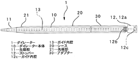
図1は、第1の実施の形態に係るダイレーター1の全体を示す側面図であり、図2は、図1のダイレーター1においてアダプター30を使用しない場合の使用形態を示す側面図である。図3は、図1のダイレーター1におけるシース20とアダプター30それぞれの側面図およびアダプター30の端面を示す端面図である。図4は、ダイレーター本体10からストッパー12を外した状態を示す分解側面図である。
Hereinafter, various preferred embodiments of the present invention will be described with reference to the drawings.
1 to 4 show a first embodiment of the present invention.
FIG. 1 is a side view showing the
図1に示したように、ダイレーター1は、円筒状のダイレーター本体10と、該ダイレーター本体10に外挿可能な円筒状のシース20と、該シース20の後端に続けてダイレーター本体10に外挿可能な円筒状のアダプター30とから構成されている。
As shown in FIG. 1, the
ダイレーター本体10は、先端部11が先細りのテーパー状に形成された円筒体である。ダイレーター本体10の素材は、例えばポリエチレンである。
The
このダイレーター本体10には、不図示のガイドワイヤーを通すためのガイド内腔13が先端部11から後端部まで長手方向に貫通している。また、ダイレーター本体10は、その後端部に着脱可能なストッパー12を備えている。
A
ダイレーター本体10の後端部には雌螺子部が形成されており、ストッパー12には、この雌螺子部に螺合するように頭部12aの先に雄螺子部12bが形成されている。
A female screw portion is formed at the rear end portion of the dilator
ストッパー12は、雄螺子部12bの先端から頭部12aまで長手方向にガイドワイヤーを通すためのガイド内腔12cが貫通している。これにより、ストッパー12をダイレーター本体10に螺着した状態でストッパー12の頭部12aからダイレーター本体10の先端までガイド内腔12c,13が連通して貫通するので、ガイドワイヤーを通すことができる。ストッパー12の頭部12aは、少なくともアダプター30の内径よりも大きい外径の円筒状に形成されている。なお、頭部12aは、アダプター30内に入り込まない大きさのものであれば、円筒状に限られない。
The
シース20は、ダイレーター本体10よりも全長が短い円筒体であり、先端部21が先細りのテーパー状に形成されている。シース20の内径はダイレーター本体10の外径と略同じ大きさである。この先端部21は、ダイレーター本体10にシース20を外挿したときに、ダイレーター本体10の先端部11のテーパー状が始まる始端の外周面に先端が滑らかに連続するように形成されている。
The
図示したテーパー状の先端部21は、ダイレーター本体10の先端部11がテーパー状に先細る角度と同じ角度で先細っている。言い換えると、シース20の先端部21は、ダイレーター本体10の先端部11がテーパー状に拡がる角度と同じ角度でテーパー状に拡がっている。
The tapered
アダプター30は、その内径および外径がともにシース20の内径および外径と同じ円筒体であり、シース20の後端に続けてダイレーター本体10に外挿するものである。このアダプター30は、シース20とストッパー12との間に外挿させることにより、シース20の位置決めをすることができる。すなわち、アダプター30は、前記のようにダイレーター本体10に外挿したときに、シース20の先端部21がダイレーター本体10の先端部11のテーパー状の始端の位置に一致するように全長が定められている。
The
次に第1の実施の形態に係るダイレーター1の作用を説明する。
体表面に開けた穿刺孔からカテーテル等の医療用器具を体腔内に挿入する際に、穿刺孔を拡張するためのダイレーター1を使用するときは、ダイレーター本体10の後端部からストッパー12を外して、シース20の先端部21をダイレーター本体10の後端部から外挿して行く。シース20は、その先端部21がダイレーター本体10の先端部11のテーパー状の始端の付近の手前に達するまで外挿する。
Next, the operation of the
When a
次に、アダプター30をダイレーター本体10の後端部から外挿する。アダプター30は、その先端がダイレーター1の後端部に後端の付近に至るまで外挿する。
Next, the
この後に、ダイレーター本体10の後端部の雌螺子部にストッパー12の雄螺子部12bを螺合させて、ストッパー12をダイレーター本体10に固定する。ストッパー12がねじ込まれながらダイレーター本体10の先端部11の方向に進む際に、ストッパー12の頭部12aがアダプター30を押し進める。これにより、アダプター30がシース20の後端を押して、シース20は、その先端がダイレーター本体10の先端部11のテーパー状が始まる始端に位置するように位置決めされる。
Thereafter, the
このようにダイレーター本体10にシース20、アダプター30を組み付けたダイレーター1は、ダイレーター本体10の先端部11に形成されたテーパー状が始まる始端からシース20の先端部21に形成されたテーパー状部分がスムーズに連続した状態となる。したがって、ダイレーター1を体表面に開けた穿刺孔に挿入したときに、シース20の外径まで穿刺孔をスムーズに拡張することができる。
In this manner, the
次に、体表面に開けた穿刺孔に予め通してあるガイドワイヤーをダイレーター本体10のガイド内腔13およびガイド内腔13に連通しているストッパー12のガイド内腔12cに通し、このガイドワイヤーに沿ってダイレーター1を体腔内の所望の位置まで挿入する。
Next, a guide wire previously passed through a puncture hole opened in the body surface is passed through the
このようにして穿刺孔を拡張したら、ダイレーター1を抜き取り、ガイドワイヤーに沿ってカテーテル等の医療用器具を拡張した穿刺孔から体腔内に挿入することができる。
When the puncture hole is expanded in this way, the
ダイレーター1は、アダプター30を用いずに使用することもできる。図2にはそのような使用例が例示されている。図示したように、シース20は、その後端がダイレーター本体10のストッパー12に接する位置付近になるように外挿されている。このため、シース20の先端がダイレーター本体10のテーパー状の始まる始端よりもストッパー12側に離れた位置に在るようにしている。
The
この場合、ダイレーター本体10のテーパー状が始まる始端からシース20の先端部21までの間には、ダイレーター本体10の同径の胴部が現れる。これにより、図1に示した使用態様ではダイレーター本体10の先端部11からシース20の外径まで一気に穿刺孔を拡張することになるが、図2に示したような使用態様では、一旦、ダイレーター本体10の先端部11からダイレーター本体10の外径まで穿刺孔を拡張し、その後、さらにシース20の外径まで穿刺孔を拡張することになる。
In this case, a body portion of the same diameter of the
したがって、2つの異なる使用態様でダイレーター1を使用することができる。なお、シース20の位置は図1、図2に示した位置に限られない。図1の使用態様では、図示した位置よりも先端部21をダイレーター本体10のテーパー状の始まる始端よりも10mm程度まで後方位置に在るようにしてもよい。また図2の使用態様では、図示した位置よりも先端部21をダイレーター本体10の先端部11に近づけてもよい。
Accordingly, the
なお、シース20およびアダプター30をダイレーター本体10に外挿するときは、それらをダイレーター本体10の先端部11側から外挿しても良い。
Note that when the
次に、第2の実施の形態について説明する。
図5から図8までは、本発明の第2の実施の形態を示している。
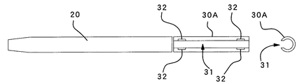
図5は、第2の実施の形態に係るダイレーター1Aの全体を示す側面図であり、図6は、図5のダイレーター1Aにおいてアダプター30Aを使用しない場合の使用形態を示す側面図である。図7は、図5のダイレーター1Aにおけるシース20とアダプター30Aそれぞれの側面図およびアダプター30Aの端面を示す端面図である。図8は、図5のダイレーター本体10Aを示す側面図である。
Next, a second embodiment will be described.
5 to 8 show a second embodiment of the present invention.
FIG. 5 is a side view showing the entirety of the dilator 1A according to the second embodiment, and FIG. 6 is a side view showing a use form when the
本実施の形態に係るダイレーター1Aでは、アダプター30Aが第1の実施の形態におけるアダプター30とは異なっている点、およびストッパー12Aがダイレーター本体10Aと一体となっている点が第1の実施の形態とは異なっている。なお、第1の実施の形態と同種の部位には同一符号を付し重複した説明を省略する。
In the dilator 1A according to the present embodiment, the first embodiment is that the
図5および図7に示したように、アダプター30Aは、円筒体の先端から後端まで長手方向に切欠いたスリット31が形成されている。したがって、アダプター30Aをダイレーター本体10Aに装着する場合、ダイレーター本体10Aの先端部11側から外挿してもよいが、スリット31からダイレーター本体10Aに嵌め込むようにして外嵌することもできる。また、スリット31をダイレーター本体10Aから外す場合、ダイレーター本体10Aの先端部11側から抜き取るようにしてもよいが、スリット31から取り外すこともできる。
As shown in FIGS. 5 and 7, the
スリット31には、その相対する端面それぞれの両端付近に凹部32が形成されている。この凹部32は、ダイレーター本体10Aに装着してあるアダプター30Aを取り外す際に、ジグを入れたり、使用者が指の爪を立てたりしてスリット31を拡げ易くするためのものである。なお、凹部32を設ける位置は図示した位置に限られず、スリット31の相対する端面それぞれの一部であれば何処であってもよい。
The
図5、図6および図7に示したように、ダイレーター本体10Aは、その後端部にストッパー12Aが一体に設けられている。これにより、ダイレーター1Aは、第1の実施の形態に係るダイレーター1よりも部材の数が1つ少なくなっている。
As shown in FIGS. 5, 6, and 7, the dilator
第2の実施の形態に係るダイレーター1Aの作用は、ダイレーター本体10Aにアダプター30Aを装着する仕方がダイレーター本体10Aへの外挿の他にダイレーター本体10Aへ嵌め込むことができる点を除いて、第1の実施の形態に係るダイレーター1の作用と同様であるので、その説明を省略する。
The action of the dilator 1A according to the second embodiment is that the manner in which the
なお、アダプター30Aをダイレーター本体10Aに外嵌させるときは、スリット31をダイレーター本体10Aに沿うように当ててから、スリット31からダイレーター本体10Aに外嵌するようにアダプター30Aおよびダイレーター本体10Aを互いに押し付ければ良い。スリット31がダイレーター本体10Aに押し付けられたアダプター30Aは、スリット31が拡がるので、ダイレーター本体10Aに容易に外嵌させることができる。アダプター30Aがダイレーター本体10Aに完全に外嵌したときは、アダプター30Aは、その弾性により、拡がったスリット31が閉じるように形状が戻るのでダイレーター本体10Aに確実にしっかりと装着される。
また、スリット31の一端をダイレーター本体10Aに押し付けて一端側をある程度まで外嵌させてから、外嵌している端部側からもう一方の端部側まで順に押し込んでアダプター30A全体が外嵌するようにしてもよい。
When the
Further, one end of the
また、本実施の形態に係るダイレーター1Aは、次に説明する第3の実施の形態に係るダイレーター1Bのアダプター30B等に設けた突出片33を有さないので、穿刺孔から体腔内のより深部まで挿入することができる。本実施の形態に係るダイレーター1Aは、前記のようにアダプター30Aに凹部32を設けてあるので、ダイレーター本体10Aに装着してあるアダプター30Aを取り外す際に、凹部32にジグを入れたり、使用者が指の爪を凹部32に立てたりして容易にスリット31を拡げることができる。このため、アダプター30Aをダイレーター本体10Aから容易に取り外すことができる。
Further, since the dilator 1A according to the present embodiment does not have the protruding
次に、第3の実施の形態について説明する。
図9および図10は、本発明の第3の実施の形態を示している。
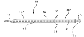
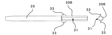
図9は、第3の実施の形態に係るダイレーター1Bの全体を示す側面図であり、図10は、図9のダイレーター1Bにおけるシース20とアダプター30Bそれぞれの側面図およびアダプター30Bの端面を示す端面図である。
Next, a third embodiment will be described.
9 and 10 show a third embodiment of the present invention.
FIG. 9 is a side view showing the entire dilator 1B according to the third embodiment, and FIG. 10 is a side view of each of the
本実施の形態に係るダイレーター1Bは、アダプター30Bが第2の実施の形態におけるアダプター30Aとは異なっている点を除いて第2の実施の形態と同様のものである。 なお、第2の実施の形態と同種の部位には同一符号を付し重複した説明を省略する。
Dilator 1B according to the present embodiment is the same as that of the second embodiment except that
図9および図10に示したように、ダイレーター1Bは、ダイレーター本体10Aの外周面から直径方向外側に互いに突出した一対の突出片33が設けられている。これらの突出片33は、アダプター30Bをダイレーター本体10Aに嵌脱する際にスリット31を拡げるためのものである。突出片33は、半円形の板状のものがアダプター30Bの端部に配設されている。
As shown in FIGS. 9 and 10, the
次に第3の実施の形態に係るダイレーター1Bの作用を説明する。
第3の実施の形態に係るダイレーター1Bは、前記のようにアダプター30Bに突出片33が設けられている点のみが第2の実施の形態に係るダイレーター1Aと異なるので、突出片33に関する作用について説明し、他の説明は省略する。
Next, the operation of the dilator 1B according to the third embodiment will be described.
The dilator 1B according to the third embodiment is different from the dilator 1A according to the second embodiment only in that the
アダプター30Bをダイレーター本体10Aに装着するには、第2の実施の形態に係るダイレーター1Aのアダプター30Aと同様に、アダプター30Bをダイレーター本体10Aの先端から外挿する方法とスリット31からダイレーター本体10Aに嵌め込む方法とがある。
In order to attach the
スリット31からダイレーター本体10Aに嵌め込む際には、スリット31をダイレーター本体10Aに沿うように当ててから、スリット31がダイレーター本体10Aに外嵌するようにスリット31およびダイレーター本体10Aを互いに押し付ければ良いが、このとき、アダプター30Bの外周面に一対の突出片33を指で摘まんでスリット31が開くように突出片33,33に力を加える。これにより、アダプター30Bをダイレーター本体10Aにより容易に外嵌させることができる。
When the
また、スリット31の一端をダイレーター本体10Aに押し付けて一端側をある程度まで外嵌させてから、外嵌している端部側からもう一方の端部側まで順に押し込んで全体が外嵌するようにする場合にも、一対の突出片33を指で摘まんで突出片33,33に力を加え、スリット31を拡げることによって一端側をより容易にダイレーター本体10Aに外嵌させることができる。
In addition, one end of the
ダイレーター本体10Aに外嵌しているアダプター30Bを外すときは、同様に一対の突出片33を指で摘まんで突出片33,33に力を加え、スリット31を拡げることにより、容易に外すことができる。なお、ダイレーター本体10Aから先にシース20を抜き取り、続いてアダプター30Bをダイレーター本体10Aから抜き取るようにしてもよい。
Similarly, when removing the
以上のように、突出片33を指で摘まんでスリット31が拡がるように力を加えることにより、ダイレーター本体10Aとのアダプター30Bの嵌脱がより容易になる。
As described above, the
なお、図示した例では、突出片33は半円形の板状のものとしてアダプター30Bの端部に設けてあるが、形状、設ける位置、設ける数等は図示した例に限られない。また、突出片33と第2の実施の形態におけるアダプター30Aに設けた凹部32とは二律背反するものではないので、アダプター30Bに凹部32を設けてもよい。
In the illustrated example, the protruding
また、図11から図13までにはダイレーター1Bの変形例が示されている。図11は、第3の実施の形態の変形例のダイレーター全体を示す側面図であり、図12は、図11のダイレーターにおけるシース20Aとアダプター30Aそれぞれの側面図およびアダプター30Aの端面を示す端面図であり、図13は、図11のダイレーター本体10Bを示す側面図である。
Moreover, the modification of the dilator 1B is shown by FIGS. 11-13. FIG. 11 is a side view showing the entire dilator of a modification of the third embodiment, and FIG. 12 shows a side view of the
この変形例では、ダイレーター本体10Bの外径がダイレーター本体10Aの外径よりも小さいものと成っている。このため、シース20Aの内径並びにアダプター30Cのスリット31cの幅および内径がダイレーター本体10Bの外径に合うように小さくなっている。
In this modification, the outer diameter of the
なお、第1の実施の形態のようにアダプター30がスリットのない円筒体である場合には、アダプター30をシース20よりも肉厚にしてシース20の外径よりも大きい外径とし、先端側を先細りのテーパー状に形成し、先端の径がシース20の外径と同じ大きさのものとすることにより、ダイレーター1で拡張できる穿刺孔の大きさをダイレーター本体10の外径→シース20の外径→アダプター30の外径の順に3段階に拡張することができる。
When the
この場合、アダプター30のテーパー状の先端を前記とは異なり、ダイレーター本体10の先端部11のテーパー状が始まる始端の外周面に滑らかに連続するように形成することにより、シース20とアダプター30のダイレーター本体10への装着位置を入れ替えてアダプター30をシースとし、シース20をアダプターとして使用することができる。これにより、穿刺孔の拡張の大きさをシース20の外径とアダプター30の外径の2つから選択することができる。
In this case, unlike the above, the tapered tip of the
以上、本発明の実施の形態を図面によって説明してきたが、具体的な構成は前述した実施の形態に限られるものではなく、本発明の要旨を逸脱しない範囲における変更や追加があっても本発明に含まれる。 The embodiments of the present invention have been described above with reference to the drawings. However, the specific configuration is not limited to the above-described embodiments, and the present invention can be changed or added without departing from the scope of the present invention. Included in the invention.
例えば、前記実施の形態では、ダイレーター本体10に着脱自在なストッパー12として、ダイレーター本体10の後端部に雌螺子部を形成し、この雌螺子部に螺合する雄螺子部12bをストッパー12に設けたものとして説明したが、雄螺子部12bに代えて互いに離接可能に変形する弾撥片を設け、該弾撥片をダイレーター本体10の内部に挿入して、弾撥片同士が離れる方向の弾撥力で弾撥片がダイレーター本体10の内部に係止するようにしてもよい。
For example, in the above-described embodiment, as the
本発明に係るダイレーターの思想は、体表面に開けた穿刺孔から医療用器具を体腔内に挿入するためのものに限られず、例えば、尿道や食道狭窄、大腸狭窄部等を拡張するブジーとしても利用することができる。 The idea of the dilator according to the present invention is not limited to the insertion of a medical instrument into a body cavity through a puncture hole opened on the body surface. Can also be used.
1…ダイレーター
1A…ダイレーター
1B…ダイレーター
10…ダイレーター本体
10A…ダイレーター本体
10B…ダイレーター本体
11…先端部
12…ストッパー
12a…頭部
12A…ストッパー
12b…雄螺子部
12c…ガイド内腔
13…ガイド内腔
20…シース
20A…シース
21…先端部
30…アダプター
30A…アダプター
30B…アダプター
30C…アダプター
31…スリット
31c…スリット
32…凹部
33…突出片
DESCRIPTION OF
Claims (6)
ガイドワイヤーを通すためのガイド内腔が長手方向に貫通し、先端部が先細りのテーパー状に形成され、後端部に着脱可能なストッパーを有する、円筒状のダイレーター本体と、
前記ダイレーター本体よりも全長が短く、先端部が先細りのテーパー状に形成された、前記ダイレーター本体に外挿可能な円筒状のシースと、
前記シースの後端に続けて前記シースと前記ストッパーとの間に外挿可能な円筒状のアダプターとを備え、
前記ダイレーター本体に前記シースを外挿し、該シースの後端に続けて前記シースにアダプターを外挿したときに、前記シースの先端が前記ダイレーター本体の先端部のテーパー状が始まる始端付近に位置するように、前記シースおよび前記アダプターの全長を設定したことを特徴とするダイレーター。 In a dilator for expanding the puncture hole in order to insert the medical instrument into the body cavity from the puncture hole opened in the body surface,
A cylindrical dilator body having a guide lumen for passing a guide wire penetrating in the longitudinal direction, a tip portion formed in a tapered shape, and a detachable stopper at the rear end portion;
A cylindrical sheath that is shorter than the dilator body and formed in a tapered shape with a tapered tip, and can be extrapolated to the dilator body;
A cylindrical adapter that can be extrapolated between the sheath and the stopper, following the rear end of the sheath,
When the sheath is extrapolated to the dilator body and an adapter is extrapolated to the sheath following the rear end of the sheath, the distal end of the sheath is near the starting end where the tip of the dilator body begins to taper. The dilator characterized by setting the full length of the sheath and the adapter so as to be positioned.
ガイドワイヤーを通すためのガイド内腔が長手方向に貫通し、先端部が先細りのテーパー状に形成され、後端部にストッパーを有する、円筒状のダイレーター本体と、
前記ダイレーター本体よりも全長が短く、先端部が先細りのテーパー状に形成された、前記ダイレーター本体に外挿可能な円筒状のシースと、
前記シースの後端に続けて前記シースと前記ストッパーとの間に外嵌可能なアダプターとを備え、
前記アダプターは、円筒体の先端から後端まで長手方向にスリットを形成して、前記ダイレーター本体に嵌脱可能としたものであり、
前記ダイレーター本体に前記シースを外挿し、該シースの後端に続けて前記シースにアダプターを外挿したときに、前記シースの先端が前記ダイレーター本体の先端部のテーパー状が始まる始端付近に位置するように、前記シースおよび前記アダプターの全長を設定したことを特徴とするダイレーター。 In a dilator for expanding the puncture hole in order to insert the medical instrument into the body cavity from the puncture hole opened in the body surface,
A cylindrical dilator main body having a guide lumen for passing a guide wire penetrating in the longitudinal direction, a tip portion formed in a tapered shape, and having a stopper at a rear end portion;
A cylindrical sheath that is shorter than the dilator body and formed in a tapered shape with a tapered tip, and can be extrapolated to the dilator body;
An adapter that can be externally fitted between the sheath and the stopper, following the rear end of the sheath,
The adapter forms a slit in the longitudinal direction from the front end to the rear end of the cylindrical body, and can be fitted to and detached from the dilator body.
When the sheath is extrapolated to the dilator body and an adapter is extrapolated to the sheath following the rear end of the sheath, the distal end of the sheath is near the starting end where the tip of the dilator body begins to taper. The dilator characterized by setting the full length of the sheath and the adapter so as to be positioned.
Priority Applications (1)
| Application Number | Priority Date | Filing Date | Title |
|---|---|---|---|
| JP2011213062A JP5199434B2 (en) | 2011-09-28 | 2011-09-28 | Dilator |
Applications Claiming Priority (1)
| Application Number | Priority Date | Filing Date | Title |
|---|---|---|---|
| JP2011213062A JP5199434B2 (en) | 2011-09-28 | 2011-09-28 | Dilator |
Publications (2)
| Publication Number | Publication Date |
|---|---|
| JP2013070872A JP2013070872A (en) | 2013-04-22 |
| JP5199434B2 true JP5199434B2 (en) | 2013-05-15 |
Family
ID=48475859
Family Applications (1)
| Application Number | Title | Priority Date | Filing Date |
|---|---|---|---|
| JP2011213062A Active JP5199434B2 (en) | 2011-09-28 | 2011-09-28 | Dilator |
Country Status (1)
| Country | Link |
|---|---|
| JP (1) | JP5199434B2 (en) |
Cited By (2)
| Publication number | Priority date | Publication date | Assignee | Title |
|---|---|---|---|---|
| US10967152B2 (en) | 2017-03-10 | 2021-04-06 | Abiomed, Inc. | Expandable introducer sheath for medical device |
| US11660434B2 (en) | 2020-02-03 | 2023-05-30 | Abiomed, Inc. | Expandable sheath with interlock dilator |
Family Cites Families (5)
| Publication number | Priority date | Publication date | Assignee | Title |
|---|---|---|---|---|
| JPS60174159A (en) * | 1984-02-20 | 1985-09-07 | オリンパス光学工業株式会社 | Expander |
| JP4264367B2 (en) * | 2004-02-20 | 2009-05-13 | テルモ株式会社 | Puncture tool |
| JP5036858B2 (en) * | 2005-10-12 | 2012-09-26 | 裕 鈴木 | Fistula dilator used for gastrostomy |
| US20070255208A1 (en) * | 2006-04-28 | 2007-11-01 | Mcmichael Donald J | Percutaneous dilation apparatus |
| US8211136B2 (en) * | 2007-08-31 | 2012-07-03 | Kimberly-Clark Worldwide, Inc. | Stoma dilator |
-
2011
- 2011-09-28 JP JP2011213062A patent/JP5199434B2/en active Active
Cited By (5)
| Publication number | Priority date | Publication date | Assignee | Title |
|---|---|---|---|---|
| US10967152B2 (en) | 2017-03-10 | 2021-04-06 | Abiomed, Inc. | Expandable introducer sheath for medical device |
| US11697002B2 (en) | 2017-03-10 | 2023-07-11 | Abiomed, Inc. | Expandable introducer sheath for medical device |
| US11969563B2 (en) | 2017-03-10 | 2024-04-30 | Abiomed, Inc. | Expandable introducer sheath for medical device |
| US11660434B2 (en) | 2020-02-03 | 2023-05-30 | Abiomed, Inc. | Expandable sheath with interlock dilator |
| US11944770B2 (en) | 2020-02-03 | 2024-04-02 | Abiomed, Inc. | Expandable sheath with interlock dilator |
Also Published As
| Publication number | Publication date |
|---|---|
| JP2013070872A (en) | 2013-04-22 |
Similar Documents
| Publication | Publication Date | Title |
|---|---|---|
| US10870143B2 (en) | Connection structure and connection method | |
| JP3917332B2 (en) | Endoscope operation wire connecting part | |
| JP6203926B2 (en) | Method and apparatus for guiding a suture | |
| JP2009268763A (en) | Operation section of treatment instrument for endoscope | |
| US20070149850A1 (en) | Endoscope endcap attachment tool | |
| JP5199434B2 (en) | Dilator | |
| US20090223028A1 (en) | Magazine type clipping device | |
| US9566673B2 (en) | Snare introducer | |
| JP5246394B2 (en) | Clip, clip unit and clip device | |
| JP6013659B1 (en) | Treatment tool | |
| KR101735022B1 (en) | Tampon applicator assembly | |
| JP6722907B2 (en) | Endoscope catheter | |
| JP5583390B2 (en) | Indwelling catheter removal aid | |
| KR20210151787A (en) | Cutting tool cleaning accessories | |
| CN111093578B (en) | Tampon applicator | |
| CA2592257A1 (en) | Resheathing tool | |
| JP4495501B2 (en) | Endoscopic treatment tool for endoscope | |
| JP5848499B2 (en) | Indwelling catheter changer | |
| JP6745034B2 (en) | Reducing tool and insertion device kit | |
| JP6829563B2 (en) | Basket forceps | |
| JP5976752B2 (en) | Indwelling catheter exchange device | |
| JP3590235B2 (en) | Hair transplanter | |
| JP7016252B2 (en) | Basket-type endoscope treatment tool | |
| JP2014230580A (en) | Basket retainer | |
| JP5186246B2 (en) | Operation unit of disposable treatment instrument for endoscope |
Legal Events
| Date | Code | Title | Description |
|---|---|---|---|
| A521 | Request for written amendment filed |
Free format text: JAPANESE INTERMEDIATE CODE: A821 Effective date: 20110928 |
|
| A621 | Written request for application examination |
Free format text: JAPANESE INTERMEDIATE CODE: A621 Effective date: 20111028 |
|
| TRDD | Decision of grant or rejection written | ||
| A01 | Written decision to grant a patent or to grant a registration (utility model) |
Free format text: JAPANESE INTERMEDIATE CODE: A01 Effective date: 20130205 |
|
| A61 | First payment of annual fees (during grant procedure) |
Free format text: JAPANESE INTERMEDIATE CODE: A61 Effective date: 20130207 |
|
| FPAY | Renewal fee payment (event date is renewal date of database) |
Free format text: PAYMENT UNTIL: 20160215 Year of fee payment: 3 |
|
| R150 | Certificate of patent or registration of utility model |
Ref document number: 5199434 Country of ref document: JP Free format text: JAPANESE INTERMEDIATE CODE: R150 |
|
| R250 | Receipt of annual fees |
Free format text: JAPANESE INTERMEDIATE CODE: R250 |
|
| R250 | Receipt of annual fees |
Free format text: JAPANESE INTERMEDIATE CODE: R250 |
|
| R250 | Receipt of annual fees |
Free format text: JAPANESE INTERMEDIATE CODE: R250 |
|
| R250 | Receipt of annual fees |
Free format text: JAPANESE INTERMEDIATE CODE: R250 |
|
| R250 | Receipt of annual fees |
Free format text: JAPANESE INTERMEDIATE CODE: R250 |
|
| R250 | Receipt of annual fees |
Free format text: JAPANESE INTERMEDIATE CODE: R250 |
|
| R250 | Receipt of annual fees |
Free format text: JAPANESE INTERMEDIATE CODE: R250 |
|
| R250 | Receipt of annual fees |
Free format text: JAPANESE INTERMEDIATE CODE: R250 |
|
| R250 | Receipt of annual fees |
Free format text: JAPANESE INTERMEDIATE CODE: R250 |