JP5196893B2 - COMMUNICATION SYSTEM, COMMUNICATION DEVICE, AND COMMUNICATION METHOD FOR COMMUNICATION SYSTEM - Google Patents
COMMUNICATION SYSTEM, COMMUNICATION DEVICE, AND COMMUNICATION METHOD FOR COMMUNICATION SYSTEM Download PDFInfo
- Publication number
- JP5196893B2 JP5196893B2 JP2007181324A JP2007181324A JP5196893B2 JP 5196893 B2 JP5196893 B2 JP 5196893B2 JP 2007181324 A JP2007181324 A JP 2007181324A JP 2007181324 A JP2007181324 A JP 2007181324A JP 5196893 B2 JP5196893 B2 JP 5196893B2
- Authority
- JP
- Japan
- Prior art keywords
- communication
- data
- control data
- transmitting
- daisy chain
- Prior art date
- Legal status (The legal status is an assumption and is not a legal conclusion. Google has not performed a legal analysis and makes no representation as to the accuracy of the status listed.)
- Expired - Fee Related
Links
Images


Classifications
-
- H—ELECTRICITY
- H04—ELECTRIC COMMUNICATION TECHNIQUE
- H04N—PICTORIAL COMMUNICATION, e.g. TELEVISION
- H04N7/00—Television systems
- H04N7/18—Closed-circuit television [CCTV] systems, i.e. systems in which the video signal is not broadcast
- H04N7/181—Closed-circuit television [CCTV] systems, i.e. systems in which the video signal is not broadcast for receiving images from a plurality of remote sources
-
- H—ELECTRICITY
- H04—ELECTRIC COMMUNICATION TECHNIQUE
- H04N—PICTORIAL COMMUNICATION, e.g. TELEVISION
- H04N21/00—Selective content distribution, e.g. interactive television or video on demand [VOD]
- H04N21/40—Client devices specifically adapted for the reception of or interaction with content, e.g. set-top-box [STB]; Operations thereof
- H04N21/41—Structure of client; Structure of client peripherals
- H04N21/422—Input-only peripherals, i.e. input devices connected to specially adapted client devices, e.g. global positioning system [GPS]
- H04N21/4223—Cameras
-
- H—ELECTRICITY
- H04—ELECTRIC COMMUNICATION TECHNIQUE
- H04N—PICTORIAL COMMUNICATION, e.g. TELEVISION
- H04N21/00—Selective content distribution, e.g. interactive television or video on demand [VOD]
- H04N21/40—Client devices specifically adapted for the reception of or interaction with content, e.g. set-top-box [STB]; Operations thereof
- H04N21/43—Processing of content or additional data, e.g. demultiplexing additional data from a digital video stream; Elementary client operations, e.g. monitoring of home network or synchronising decoder's clock; Client middleware
- H04N21/436—Interfacing a local distribution network, e.g. communicating with another STB or one or more peripheral devices inside the home
- H04N21/4363—Adapting the video or multiplex stream to a specific local network, e.g. a IEEE 1394 or Bluetooth® network
-
- H—ELECTRICITY
- H04—ELECTRIC COMMUNICATION TECHNIQUE
- H04N—PICTORIAL COMMUNICATION, e.g. TELEVISION
- H04N23/00—Cameras or camera modules comprising electronic image sensors; Control thereof
- H04N23/60—Control of cameras or camera modules
- H04N23/66—Remote control of cameras or camera parts, e.g. by remote control devices
-
- H—ELECTRICITY
- H04—ELECTRIC COMMUNICATION TECHNIQUE
- H04N—PICTORIAL COMMUNICATION, e.g. TELEVISION
- H04N23/00—Cameras or camera modules comprising electronic image sensors; Control thereof
- H04N23/90—Arrangement of cameras or camera modules, e.g. multiple cameras in TV studios or sports stadiums
Description
本発明は、複数の通信装置がデイジーチェーン接続されたシステムにおけるデータの転送技術に関するものである。 The present invention relates to a data transfer technique in a system in which a plurality of communication devices are connected in a daisy chain.
複数のカメラ端末とコントローラとがネットワークで接続された映像伝送システムが存在する。例えば、1台のコントローラと複数のカメラとがデジタルバスでデイジーチェーン接続されたシステムが特許文献1に開示されている。また、1台のカメラ制御装置と複数の監視カメラとが通信ラインを兼ねるAC電源ラインに共通バス接続されたシステムが特許文献2に開示されている。
There is a video transmission system in which a plurality of camera terminals and a controller are connected via a network. For example,
いずれの例においても、映像データを確実に伝送して映像のコマ落ち等の発生を抑制するために、各カメラに対して使用すべき転送タイムスロットを指定した時分割多重通信を行い、当該転送タイムスロット内で各カメラの映像データが伝送される。 In either example, in order to reliably transmit video data and suppress the occurrence of video frame dropping, etc., time division multiplex communication specifying a transfer time slot to be used for each camera is performed and the transfer is performed. Video data of each camera is transmitted in the time slot.
各カメラに対して転送タイムスロットを指定するということは、当然のことながら個々のカメラに対して事前に何らかの方法でID番号やアドレス番号等の個体識別情報又は宛先識別番号を設定しておく必要があるということである。しかしながら、これをユーザが手動で設定するのはユーザビリティが良くない。何らかのプロトコルにより自動的に設定する方法も考えられるが、処理負担が増大し、機器の構成が複雑になる。 Specifying a transfer time slot for each camera is, of course, necessary to set individual identification information such as ID number or address number or destination identification number in advance for each camera in some way. Is that there is. However, it is not good for the user to set this manually. Although a method of automatically setting by some protocol can be considered, the processing load increases and the configuration of the device becomes complicated.
また通常、映像データの伝送に先立ちネットワーク上の機器構成等を確認する通信が行われる。そもそもネットワーク上に何台のノードが接続されているのかさえ解らない状態では、転送タイムスロットを指定して行う時分割多重通信は実施することができない。従って、このときに使用される通信プロトコルは、転送タイムスロットを使用した通信プロトコルとは全く別物となり、プロトコルスタックの構成がどうしても複雑となって処理負担が重くなってしまう。 Usually, communication for confirming the device configuration on the network is performed prior to transmission of video data. In the first place, when it is not known how many nodes are connected on the network, the time division multiplex communication performed by designating the transfer time slot cannot be performed. Accordingly, the communication protocol used at this time is completely different from the communication protocol using the transfer time slot, and the configuration of the protocol stack is inevitably complicated and the processing load becomes heavy.
ところで、複数のカメラ端末の映像を合成して一画面で表示させる場合、各カメラ端末の映像フレーム周期は同期しているのが望ましい。映像フレーム周期が同期していれば映像合成は簡単な処理で事足りるし、撮影タイミングが一致しているので、各カメラ端末が撮影する映像の等時性も確保される。 By the way, when images from a plurality of camera terminals are combined and displayed on one screen, it is desirable that the video frame periods of the camera terminals are synchronized. If the video frame periods are synchronized, video synthesis is sufficient with simple processing, and since the shooting timings match, isochronism of the video shot by each camera terminal is also ensured.
特許文献2には、割り当てられた転送タイムスロット毎にフレーム画像を出力することが言及されている。但し、これはコントローラに各カメラ端末の映像データが映像フレーム単位で順次届くだけであり、各カメラ端末での映像フレーム周期が同期していることを意味しない。つまり上記従来技術では、各カメラ端末の映像フレーム周期を同期させることについて、何らの考慮もなされていないのである。
そこで、本発明の目的は、各通信装置によるデータ転送を効率的に行うことである。 Accordingly, an object of the present invention is to efficiently perform data transfer by each communication device.
本発明の通信システムは、複数の通信装置と通信制御装置とをデイジーチェーン接続した通信システムであって、前記通信制御装置は、少なくとも、デイジーチェーンの下流側に接続する前記複数の通信装置に対して中継転送により制御データを送信する際の当該通信装置に対応する伝送遅延時間を、最も下流の通信装置に対応する動作遅延時間に対して加算することにより、前記複数の通信装置夫々について動作遅延時間を算出する算出手段と、前記複数の通信装置夫々について算出された動作遅延時間を含む制御データを前記複数の通信装置に対して送信する送信手段と、前記複数の通信装置が送信した通信データを受信する受信手段と、を有し、前記複数の各通信装置は、デイジーチェーンの上流側からの制御データを受信する制御データ受信手段と、制御データに含まれる自通信装置の動作遅延時間に基づくタイミングで通信データを取得する取得手段と、前記制御データ受信手段により受信した制御データを、デイジーチェーンの下流側に送信する制御データ送信手段と、前記制御データ送信手段により送信された制御データに含まれる動作遅延時間に基づくタイミングで取得された通信データを下流側から受信する通信データ受信手段と、自通信装置の通信データと下流側から受信した通信データとを連続して上流側に送信する通信データ送信手段と、を有することを特徴とする。 The communication system of the present invention is a communication system in which a plurality of communication devices and a communication control device are connected in a daisy chain, wherein the communication control device is at least for the plurality of communication devices connected to the downstream side of the daisy chain. a transmission delay time corresponding to the communication apparatus when transmitting the control data by the relay transfer Te, by adding for an operating delay time corresponding to the most downstream communication device, the operation delay for the plurality of communication devices each a calculating means for calculating a time, and transmission means for transmitting the control data including the operation delay time calculated for the plurality of communication devices each for the plurality of communication devices, the communication data to which the plurality of communication device transmits Each of the plurality of communication devices receives control data from the upstream side of the daisy chain. A data receiving unit, an acquiring unit that acquires communication data at the timing based on the operation delay time of the own communication device included in the control data, the control data received by the control data receiving means, for transmitting to the downstream side of the daisy chain Control data transmission means, communication data reception means for receiving communication data acquired at a timing based on the operation delay time included in the control data transmitted by the control data transmission means, and communication data of the own communication device And communication data transmission means for continuously transmitting communication data received from the downstream side to the upstream side.
本発明によれば、各通信装置において取得される通信データの周期を高い精度で同期させることが可能となる。 ADVANTAGE OF THE INVENTION According to this invention, it becomes possible to synchronize the period of the communication data acquired in each communication apparatus with high precision.
以下、本発明を適用した好適な実施形態を、添付図面を参照しながら詳細に説明する。 DESCRIPTION OF EXEMPLARY EMBODIMENTS Hereinafter, preferred embodiments to which the invention is applied will be described in detail with reference to the accompanying drawings.
<第1の実施形態>
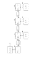
先ず、本発明の第1の実施形態について説明する。図1は、本発明の第1の実施形態に係るネットワークシステム(通信システム)の構成を示すブロック図である。
<First Embodiment>
First, a first embodiment of the present invention will be described. FIG. 1 is a block diagram showing a configuration of a network system (communication system) according to the first embodiment of the present invention.
10は、マスタノードである。11〜13は、映像データを取得可能な端末ノードである。各ノードは全二重のシリアルインタフェースを備えており、通信回線であるインタフェースケーブルによりデイジーチェーン接続されている。なお、マスタノード10は、本発明の通信制御装置の一例である。端末ノード11〜13は、本発明の通信装置の一例である。
端末ノード11〜13には、動画撮影を行うカメラ14〜16が接続されている。また、マスタノード10にはディスプレイ17が接続されている。これら全体としてカメラ14〜16で撮影した映像をディスプレイ17に表示する映像伝送システムとして機能する。
なお、図1では三台の端末ノードが接続されているが、本発明の実施にあたっては端末ノードの台数に制限はなく、任意の台数の端末ノードを接続することができる。また、各ノード間を接続するインタフェースは必ずしも全二重である必要はなく、半二重のインタフェースであってもよい。 In FIG. 1, three terminal nodes are connected. However, in implementing the present invention, the number of terminal nodes is not limited, and an arbitrary number of terminal nodes can be connected. Further, the interface connecting the nodes does not necessarily have to be full duplex, and may be a half duplex interface.
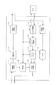
図2は、マスタノード10の構成を詳細に示すブロック図である。20は装置全体の制御を司る制御部であり、具体的にはMPUによるプログラム処理や、ハードワイヤード(hard-wired)によるシーケンサ回路等で構成される。21は端末ノード11〜13からの伝送データを受信する受信部である。受信した伝送データ中の映像データは、22のデコード処理部に送られる。端末ノード11〜13から伝送される映像データは所定の形式(例えばMotion−JPEG)でエンコードされているので、デコード処理部22でRGB形式又はYUV形式の非圧縮映像データに変換する。
FIG. 2 is a block diagram showing the configuration of the
映像データは端末ノード11〜13のそれぞれから伝送されて来るので、都合三画面分存在するが、次段の画面合成部23で一画面(例えば、各画面を横一列に並べる等)に合成される。画面合成部23で合成された映像データは、24の映像信号生成部に送られる。
Since the video data is transmitted from each of the
映像信号生成部24では、画面合成部23から送られた映像データに基づいて、ディスプレイ17への映像信号(例えば、DVI規格やHDMI規格に準拠した映像信号)を生成する。なお、制御部20の指示に基づき、画面合成部23は合成画面ではなく、特定の端末ノードからの映像データだけを映像信号生成部24に送ることもできるようになっている。従って、ユーザは、複数のカメラの合成画面表示と特定のカメラの全画面表示とを適宜選択することができるようになっている。
The video
27は、制御部20の指示に基づいて、画面上に表示する文字・記号等のOSD(On Screen Display)信号を生成するOSD信号生成部である。生成されたOSD信号は映像信号生成部24に送られ、カメラで撮影した映像と混合された形で、最終的な映像信号が生成されるようになっている。26はマスタノード10に対する操作指示を行う操作パネルで、押しボタンスイッチ等から構成される。25は制御部20の指示に基づいて、端末ノードに対する制御データを送信する送信部である。
図3は、端末ノード11〜13の構成を詳細に示すブロック図である。30は、装置全体の制御を司る制御部であり、具体的にはMPUによるプログラム処理や、ハードワイヤードによるシーケンサ回路等で構成される。また、制御部30には所定の分解能で時間計測を行うタイマカウンタが装備されている。当該タイマカウンタは、後述する撮影開始の動作タイミングを所定時間だけ遅延させる際、当該所定時間を計測するのに使用される。31は、マスタノード10からの制御データを受信する受信部(デイジーチェーン接続構成における上流側)である。受信した制御データは、制御部30及び32の中継処理部に送られる。
FIG. 3 is a block diagram showing in detail the configuration of the
中継処理部32は、バッファ用のRAM、ハードワイヤードによるシーケンサ回路等で構成される処理ブロックであり、受信した制御データの全てをそのまま中継するのか、その一部を変更して中継するのかを処理するブロックである。処理された制御データは33の送信部(デイジーチェーン接続構成における下流側)に送られ、下流の端末ノードに中継転送される。
The
なお、図3では、制御部30と中継処理部32を独立したブロックとしているが、中継処理部32の処理を制御部30のMPUによるソフトウェア処理によって実現することも、もちろん可能である。
In FIG. 3, the
34は、制御部30の指示に基づいて端末ノード11〜13に接続されるカメラ14〜16に対する制御を行うとともに、カメラ14〜16から出力される映像データを入力するカメラ制御部である。端末ノード11〜13に接続されるカメラ14〜16は、複数の解像度(縦横のピクセル数)で撮影が可能なものであり、カメラ制御部34からの指示がある度に、指定の解像度での映像を1フレームだけ撮影して出力するようになっている。この動作を所定周期(例えば60Hz)で繰り返すことで動画像(例えば60fps)を撮影することができるようになっている。
カメラ14〜16から出力される映像データは、カメラ制御部34を経て35のエンコード処理部に送られる。エンコード処理部35では、制御部30の指示に基づいてカメラから出力される非圧縮の映像データ(RGB形式又はYUV形式)を、所望の圧縮率で所定の形式(例えばMotion−JPEG)に変換する。エンコード処理された映像データは、36のフレームバッファに蓄積される。
Video data output from the
37は下流ノードからの伝送データを受信する受信部(下流側)である。受信部37で受信した伝送データは、38のFIFOに蓄積される。39は制御部30が指示する任意のデータ、フレームバッファ36に蓄積した映像データ、又はFIFO38に蓄積した伝送データを上流ノードに送信する送信部(上流側)である。
図4に制御データと、端末ノードが上流ノードに送信する伝送データのフォーマットを示す。制御データには二種類あり、図4の(a)は、マスタノード10がネットワークの構成を確認する際に送信する制御データであり、開始コード、コマンドコード(構成確認コマンド)、終了コードで構成される。図4の(a)に示すデータは、本発明の構成確認データの一例である。
FIG. 4 shows the format of control data and transmission data transmitted from the terminal node to the upstream node. There are two types of control data. FIG. 4A shows control data transmitted when the
図4の(b)は、マスタノード10が各端末ノードに対して映像の撮影を指示する際に送信する制御データであり、開始コード、コマンドフィールド1〜3、終了コードで構成される。コマンドフィールド1〜3はそれぞれ端末ノード11〜13に対するコマンドであり、コマンドコード(撮影コマンド)とそのパラメータコードで構成される。撮影パラメータコードには、解像度、映像データの圧縮率(または映像データのサイズ)、撮影開始の動作タイミングを指定する遅延時間が含まれる。なお、図4の(a)での説明では、コマンドフィールドという用語を使用しなかったが、構成確認コマンドはパラメータコードを持たないため、コマンドコードだけでコマンドフィールドを構成することになる。またパラメータコードは、開始コード、コマンドコード(構成確認コマンドコード及び撮影コマンドコード)、終了コードの何れとも同一のデータとならないように、ビット列のフォーマットが定義される。図4の(b)に示すデータは、本発明の制御データの一例である。
FIG. 4B shows control data transmitted when the
各端末ノードは、開始コードに続くコマンドフィールドの一つだけを自ノードに対するコマンドとして受け付け、それ以降のコマンドフィールドは無視する。そこで、後段の下流ノードに制御データを中継転送する際には、自ノードに対するコマンドフィールドを削除して、二番目以降のコマンドフィールドを一つずつ前詰めにする形にしてから中継転送を行うようにする。ただし(a)で示したように、各端末ノードに対して共通の動作指示を行う場合にはコマンドフィールドは一つだけなので、この場合にはコマンドフィールドを削除せずに、受信した制御データをそのまま下流ノードに中継転送する。 Each terminal node accepts only one of the command fields following the start code as a command for its own node, and ignores the subsequent command fields. Therefore, when relaying control data to downstream nodes in the subsequent stage, the command field for the own node is deleted, and the second and subsequent command fields are left-justified one by one before relaying. To. However, as shown in (a), when a common operation instruction is given to each terminal node, there is only one command field. In this case, the received control data is not deleted without deleting the command field. It is relayed and transferred to the downstream node as it is.
図4の(c)は端末ノードが上流ノードに送信する伝送データである。図4に示した通り、データ種別コード(後述するケーパビリティデータであるか映像データであるかを示すコード)、データレングス、出力データ、誤り訂正符号で構成される。 FIG. 4C shows transmission data transmitted from the terminal node to the upstream node. As shown in FIG. 4, it is composed of a data type code (a code indicating whether it is capability data to be described later or video data), a data length, output data, and an error correction code.
本実施形態におけるネットワークシステムでは、まず初めにマスタノード10がネットワークの構成を確認する。このためにマスタノード10は、図4の(a)に示す構成確認のための制御データを各端末ノードに送信する。各端末ノードはこの制御データに呼応して、自ノードの性能を示すデータ(ケーパビリティデータ)を返送する。ケーパビリティデータには、撮影可能な1秒あたりの映像フレーム数(fps)の最大値、選択可能な解像度、選択可能な映像データの圧縮率とその際の概略のデータサイズが含まれる。
In the network system according to this embodiment, first, the
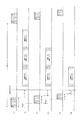
図5は、この場合におけるマスタノード10、端末ノード11〜13間で伝送されるデータを時系列的に示す図である。図5の上段から順に、図5の[1]は、マスタノード10の送信端(端末ノード11の上流側受信端)でのデータを表している。図5の[2]は、端末ノード11の上流側送信端(マスタノード10の受信端)でのデータを表している。図5の[3]は、端末ノード11の下流側送信端(端末ノード12の上流側受信端)でのデータを表している。図5の[4]は、端末ノード12の上流側送信端(端末ノード11の上流側受信端)でのデータを表している。図5の[5]は、端末ノード12の下流側送信端(端末ノード13の上流側受信端)でのデータを表している。図5の[6]は、端末ノード13の上流側送信端(端末ノード12の下流側受信端)でのデータを表している。またコマンド0とは、構成確認のためのコマンドフィールドを表す。
FIG. 5 is a diagram showing data transmitted between the
図5の[1]、[3]、[5]から分かるように、制御データはそのままの形で下流ノードに中継転送される。各端末ノードは、制御データを受信した後(より正確には終了コードを受信した後)、自ノードのケーパビリティデータを生成して、上流ノードに送信する。このとき、下流ノードからの伝送データは図3で説明したFIFO38に蓄積しておく。そして自ノードのケーパビリティデータを送信した後、FIFO38に蓄積しておいた伝送データを続けて上流ノードに送信する。FIFO38は、本発明の記録媒体の一例である。
As can be seen from [1], [3], and [5] in FIG. 5, the control data is relayed to the downstream node as it is. After receiving the control data (more accurately, after receiving the end code), each terminal node generates its own capability data and transmits it to the upstream node. At this time, transmission data from the downstream node is stored in the
このような動作を各端末ノードで行うことで、マスタノード10には端末ノード11、12、13の順で各端末ノードのケーパビリティデータが送信される(図5の[2])。なお、以上の説明から明らかなように、終了コードは制御データの終了を意味するだけでなく、コマンドの実行開始及びその結果生成される出力データの送信開始を指示する意味も有している。
By performing such an operation in each terminal node, capability data of each terminal node is transmitted to the
マスタノード10は、到来したケーパビリティデータの個数から何台の端末ノードがネットワーク上に存在するのかを、またケーパビリティデータの内容から各端末ノードがどのような性能を有しているのかを知ることができる。なお、ケーパビリティデータは、本発明の構成データの一例である。
The
次いで、マスタノード10は、撮影を指示するための制御データを各端末ノードに送信する。各端末ノードは、この制御データに呼応して撮影を行い、映像データを返送する。
Next, the
図6は、マスタノード10が撮影を指示するための制御データの構成を詳細に示す図である。図6(a)はマスタノード10が端末ノード11に送信する制御データである。図6(b)は端末ノード11が端末ノード12に送信(中継転送)する制御データである。図6(c)は端末ノード12が端末ノード13に送信(中継転送)する制御データである。図6からも明らかなように、自ノードに対するコマンドフィールドが削除されて下流ノードに中継転送される。
FIG. 6 is a diagram showing in detail the configuration of control data for the
図7は、撮影した映像データ伝送時のマスタノード10、端末ノード11〜13間で伝送されるデータを時系列的に示す図である。図7の上段から順に、図7の[1]は、マスタノード10の送信端(端末ノード11の上流側受信端)でのデータを表している。図7の[2]は、端末ノード11の上流側送信端(マスタノード10の受信端)でのデータを表している。図7の[3]は、端末ノード11の下流側送信端(端末ノード12の上流側受信端)でのデータを表している。図7の[4]は、端末ノード12の上流側送信端(端末ノード11の上流側受信端)でのデータを表している。図7の[5]は、端末ノード12の下流側送信端(端末ノード13の上流側受信端)でのデータを表している。図7の[6]は、端末ノード13の上流側送信端(端末ノード12の下流側受信端)でのデータを表している。またコマンド1〜3とは、端末ノード11〜13に対する撮影指示のためのコマンドフィールドを表す。
FIG. 7 is a diagram showing, in a time series, data transmitted between the
図6でも説明したように、図7の[1]、[3]、[5]に示す制御データは、自ノードに対するコマンドフィールドを削除して下流ノードに中継転送される。各端末ノードは制御データを受信した後、撮影パラメータに従って撮影を行い、映像データを生成して上流ノードに送信する。ただし構成確認の場合と異なり、終了コードを受信した後、直ちに撮影を実行するわけではない。図7の[1]、[3]、[5]からも分かるように、各端末ノードに制御データは、中継転送による伝送遅延時間分遅れて到達する。そこで各端末ノードでの撮影タイミング、即ち映像データの取得タイミングを一致させるため、撮影パラメータで指定された遅延時間だけ遅れて撮影を開始する。 As described in FIG. 6, the control data shown in [1], [3], and [5] in FIG. 7 is relayed and transferred to the downstream node by deleting the command field for the own node. After receiving the control data, each terminal node performs shooting according to the shooting parameters, generates video data, and transmits it to the upstream node. However, unlike the case of the configuration confirmation, shooting is not executed immediately after receiving the end code. As can be seen from [1], [3], and [5] in FIG. 7, the control data arrives at each terminal node with a delay corresponding to the transmission delay time due to the relay transfer. Therefore, in order to match the shooting timing at each terminal node, that is, the video data acquisition timing, shooting is started with a delay of the delay time specified by the shooting parameter.
中継転送による伝送遅延時間をΔt、端末ノード11〜13に対する制御データの送信時間をそれぞれt1、t2、t3、各端末ノードに対して指定すべき遅延時間をΔ1、Δ2、Δ3とすると次のように表される。
Δ3=τ・・・(式1)
Δ2=Δ3+(Δt−t2+t3)=τ+Δt−t2+t3・・・(式2)
Δ1=Δ2+(Δt−t1+t2)=τ+2Δt−t1+t3・・・(式3)
ただし、τ≧0
Assuming that transmission delay time due to relay transfer is Δt, control data transmission times for
Δ3 = τ (Formula 1)
Δ2 = Δ3 + (Δt−t2 + t3) = τ + Δt−t2 + t3 (Expression 2)
Δ1 = Δ2 + (Δt−t1 + t2) = τ + 2Δt−t1 + t3 (Expression 3)
However, τ ≧ 0
端末ノード13は終端ノードであるからΔ3は0以上の任意の遅延時間でよく、上流の端末ノードに対してはΔ3に加えて、中継転送による伝送遅延時間から制御データが中継転送の際、短くなる分を補正した値を指定するわけである。図7の[2]、[4]、[6]からも分かるように、上流の端末ノードほど遅延時間は大きく指定される。
Since the
撮影後、所定形式でのエンコード処理が終了した後、生成した映像データは上流ノードに送信される。このとき、下流ノードからの伝送データは図3で説明したFIFO38に蓄積しておく。そして自ノードの映像データを送信した後、FIFO38に蓄積しておいた伝送データを続けて上流ノードに送信(中継転送)する。このような動作を各端末ノードで行うことで、マスタノード10には端末ノード11、12、13の順で各端末ノードの映像データが送信される(図7の[2])。
After shooting, after encoding processing in a predetermined format is completed, the generated video data is transmitted to the upstream node. At this time, transmission data from the downstream node is stored in the
以上の動作を所定周期、例えば60Hzで繰り返すことで60fpsの動画像をマスタノード10に接続されたディスプレイ17に表示することができるわけである。しかも各端末ノードでの動画像は撮影タイミングが一致しており、映像フレーム周期が同期した状態でディスプレイ17に表示される。
By repeating the above operation at a predetermined cycle, for example, 60 Hz, a moving image of 60 fps can be displayed on the
次に、図8〜図10のフローチャートを用いて、本実施形態に係るネットワークシステムの動作につき説明する。 Next, the operation of the network system according to the present embodiment will be described with reference to the flowcharts of FIGS.
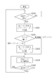
図8は、マスタノード10の動作の流れを示すフローチャートである。マスタノード10は、まずステップ100にて、構成確認コマンドフィールド(コマンド0)を内包する制御データを送信し、ステップ101で各端末ノードからのケーパビリティデータの返送を待機する。
FIG. 8 is a flowchart showing an operation flow of the
マスタノード10は、各端末ノードからケーパビリティデータを受信すると、ステップ102でネットワークに接続された端末ノードの台数とそれぞれの撮影性能とを確認する。続くステップ103では、マスタノード10は、ステップ102において確認した情報から実行可能な動画形式(1秒あたりの映像フレーム数、各端末ノードでの解像度及び映像データの圧縮率)の候補一覧をOSDによりディスプレイ17に表示する。そして、ステップ104にて、マスタノード10は、ユーザによる候補一覧からの選択を待機する。選択指示は図2に示す操作部26を介して行われる。
When the
選択指示があると、ステップ105にて、マスタノード10は、ユーザの選択に基づいて、各端末ノードに対する撮影パラメータを決定する。
When there is a selection instruction, in step 105, the
続くステップ106において、マスタノード10は、ステップ105で決定した値をパラメータコードとした撮影コマンドフィールド(コマンド1〜3)を内包した制御データを送信し、ステップ107で各端末ノードからの映像データの返送を待機する。
In the subsequent step 106, the
ここで各端末ノードに対する撮影パラメータは同じ値である必要はなく、解像度、映像データの圧縮率は各端末ノードに対して個別に決定してよい。また撮影開始の動作タイミングを指定する遅延時間は、上記式1〜3で説明したように各端末ノード毎に異なった値を指定する。
Here, the shooting parameters for each terminal node need not have the same value, and the resolution and the compression rate of the video data may be determined individually for each terminal node. In addition, as described in the
ところで、1秒あたりの映像フレーム数(fps)は、各端末ノードに撮影パラメータとして指示されるのではなく、マスタノード10が制御データをどれほどの周期で繰り返し送信するかによって決定する。従って1秒あたりの映像フレーム数(fps)は各端末ノードで共通のものとなる。
By the way, the number of video frames per second (fps) is not instructed as a shooting parameter to each terminal node, but is determined by how many cycles the
また、映像フレーム数を優先して(高fpsにして)、画質を下げる(低解像度、高圧縮率)こともできるし、逆に画質を優先して(高解像度、低圧縮率)、映像フレーム数を下げるのでもよい。どちらで撮影を実行するかはユーザの選択指示による。要は返送される1フレーム分の映像データが、ノード間を接続するシリアルインタフェースの最大伝送帯域を越えることがないように、1秒あたりの映像フレーム数(fps)と撮影パラメータが決定されていればよい。 It is also possible to prioritize the number of video frames (high fps) and lower the image quality (low resolution, high compression rate), or conversely, prioritize image quality (high resolution, low compression rate), video frames. The number may be lowered. Which is used for shooting depends on a selection instruction from the user. In short, the number of video frames per second (fps) and shooting parameters are determined so that the returned video data for one frame does not exceed the maximum transmission bandwidth of the serial interface connecting the nodes. That's fine.
再び図8のフローチャートの説明に戻る。マスタノード10は、各端末ノードから映像データを受信すると、ステップ108でデコード処理を行い、ステップ109で各端末ノードからの映像を一画面に合成する。続くステップ110で、マスタノード10は、合成後の映像データをディスプレイ17に表示する。なお、特定の端末ノードからの映像データだけを表示する場合には、ステップ109の合成処理は割愛してよい。以降は所定の周期、すなわちユーザが選択指示した映像フレーム数(fps)に対応する周期で、ステップ106からの処理を繰り返し実行する。
Returning to the description of the flowchart of FIG. When the
図9は、端末ノードの制御データの中継転送に関する動作の流れを示すフローチャートである。 FIG. 9 is a flowchart showing a flow of operations related to relay transfer of control data of a terminal node.
端末ノードは、先ずステップ200にて、制御データの受信を待機し、制御データを受信すると、ステップ201で自ノードに対するコマンドフィールドを抽出する。 First, in step 200, the terminal node waits for reception of control data. When receiving the control data, the terminal node extracts a command field for the own node in step 201.
続いて、端末ノードは、ステップ202で抽出したコマンドフィールドが撮影コマンドフィールドであるか、構成確認コマンドフィールドであるかを判定する。撮影コマンドフィールドである場合、端末ノードは、ステップ203にて、自ノードに対するコマンドフィールドを削除する。そして、端末ノードは、ステップ204で一部が削除された制御データを下流ノードに中継転送する。続いて、端末ノードは、ステップ205にて、制御データの転送が終了したか否かを判定する。制御データの転送が終了すると、処理はステップ200を介してステップ202に戻る。 Subsequently, the terminal node determines whether the command field extracted in step 202 is a shooting command field or a configuration confirmation command field. If it is a shooting command field, the terminal node deletes the command field for its own node in step 203. Then, the terminal node relays and transfers the control data partially deleted in step 204 to the downstream node. Subsequently, in step 205, the terminal node determines whether or not the transfer of control data has been completed. When the transfer of control data is completed, the process returns to step 202 via step 200.
一方、ステップ202において、構成確認コマンドフィールドであると判定された場合、端末ノードは、コマンドフィールドの削除は行わず、ステップ204、205で受信した制御データを下流ノードにそのまま中継転送する。端末ノードは、以上示したステップ200〜205の処理を繰り返し実行する。 On the other hand, if it is determined in step 202 that the field is a configuration confirmation command field, the terminal node does not delete the command field, and relays and transfers the control data received in steps 204 and 205 to the downstream node as it is. The terminal node repeatedly executes the processes in steps 200 to 205 described above.
図10は、端末ノードにおける自ノードの出力データの送信及び下流ノードからの伝送データの中継転送に関する動作の流れを示すフローチャートである。 FIG. 10 is a flowchart showing a flow of operations relating to transmission of output data of the own node and relay transfer of transmission data from the downstream node in the terminal node.
端末ノードは、ステップ300で制御データの受信を待機し、制御データを受信すると、ステップ301で自ノードに対するコマンドフィールドを抽出する。 In step 300, the terminal node waits for reception of control data. When receiving the control data, the terminal node extracts a command field for the own node in step 301.
続くステップ302では、端末ノードは、抽出したコマンドフィールドが撮影コマンドフィールドであるか、構成確認コマンドフィールドであるかを判定する。構成コマンドフィールドである場合、端末ノードは、ステップ303で終了コードの受信を待機し、終了コード受信後、ステップ304でケーパビリティデータを生成する。 In subsequent step 302, the terminal node determines whether the extracted command field is a shooting command field or a configuration confirmation command field. In the case of the configuration command field, the terminal node waits for reception of the end code in step 303, and after receiving the end code, generates capability data in step 304.
一方、ステップ302にて撮影コマンドフィールドであると判定された場合、端末ノードは、ステップ305で終了コードの受信を待機する。終了コード受信後、端末ノードは、ステップ306で指定された遅延時間のタイミングで映像の撮影を行って、映像データ(エンコード処理済み)を生成する。 On the other hand, if it is determined in step 302 that the field is a shooting command field, the terminal node waits for reception of an end code in step 305. After receiving the end code, the terminal node captures the video at the timing of the delay time specified in step 306 to generate video data (encoded).
いずれのコマンドフィールドの場合も、端末ノードは、データ生成後にステップ307で生成した出力データを上流ノードに送信する。そしてステップ308にて、端末ノードは、下流ノードから受信した全ての伝送データを上流ノードに中継転送し、ステップS309にて中継転送が終了したか否かを判定する。中継転送が終了するまでステップS308の中継転送処理が実行される。端末ノードは、以上説明したステップ300〜309の処理を繰り返し実行する。 In any command field, the terminal node transmits the output data generated in step 307 after the data generation to the upstream node. In step 308, the terminal node relays and transfers all transmission data received from the downstream node to the upstream node. In step S309, the terminal node determines whether or not the relay transfer is completed. The relay transfer process in step S308 is executed until the relay transfer ends. The terminal node repeatedly executes the processes in steps 300 to 309 described above.
以上説明してきたように、本実施形態におけるネットワークシステムでは構成確認時と映像データ伝送時とで共通な、処理負担の軽いシンプルな通信プロトコルを使用したネットワークシステムを実現することができる。しかも、本実施形態におけるネットワークシステムでは、データ伝送を行うにあたって各端末ノードに対して使用すべき転送タイムスロットを指定することはしない。従って、個体識別情報又は宛先識別番号等の設定が全く不要であり、しかも、そのことを複雑なプロトコル処理を必要とすることなく簡単な機器構成で実現することができる。 As described above, the network system according to the present embodiment can realize a network system using a simple communication protocol with a light processing burden that is common between the configuration confirmation and the video data transmission. In addition, in the network system according to the present embodiment, a transfer time slot to be used for each terminal node is not designated when performing data transmission. Accordingly, it is not necessary to set individual identification information or a destination identification number, and this can be realized with a simple device configuration without requiring complicated protocol processing.
また、本実施形態におけるネットワークシステムでは、各端末ノードが撮影する映像のフレーム周期を高い精度で同期させることができるという優れた効果を有する。 In addition, the network system according to the present embodiment has an excellent effect that the frame period of video captured by each terminal node can be synchronized with high accuracy.
<第2の実施形態>
上記の実施形態においては、受信した制御データの一部を削除して下流ノードに中継転送する構成になっているが、削除ではなく異なる制御コードに書き換えて下流ノードに中継転送することでも同様の効果を得ることができる。すなわち、ノードに対して何らの作用も及ぼさないヌルコードを定義しておき、自ノードに対するコマンドフィールドを上記ヌルコードに書き換えて無効にしてから中継転送すればよい。なお、本実施形態に係るネットワークシステムの構成は、上述した第1の実施形態に係るネットワークシステムの構成と同様である。
<Second Embodiment>
In the above embodiment, a part of the received control data is deleted and relay-transferred to the downstream node. However, it is also possible to rewrite to a different control code instead of deletion and relay-transfer to the downstream node. An effect can be obtained. That is, it is only necessary to define a null code that does not have any effect on the node, rewrite the command field for the node to the null code, invalidate it, and perform relay transfer. Note that the configuration of the network system according to the present embodiment is the same as the configuration of the network system according to the first embodiment described above.
図11は、本発明の第2の実施形態における制御データの構成を詳細に示す図である。図11(a)は、マスタノード10が端末ノード11に送信する制御データである。図11(b)は、端末ノード11が端末ノード12に送信(中継転送)する制御データである。図11(c)は、端末ノード12が端末ノード13に送信(中継転送)する制御データである。図11からも明らかなように、自ノードに対するコマンドフィールドがヌルコードに書き換えられて、下流のノードに中継転送される。
FIG. 11 is a diagram showing in detail the configuration of control data in the second embodiment of the present invention. FIG. 11A shows control data transmitted from the
或いは、図12に示すように制御データを構成してもよい。即ち、図12(a)は、マスタノード10が端末ノード11に送信する制御データである。図12(b)は、端末ノード11が端末ノード12に送信する制御データである。図12(c)は、端末ノード12が端末ノード13に送信する制御データである。このように、次段の端末ノードに対するコマンドフィールドの直前を開始コードとし、それに前置する全ての制御コードをヌルコードに書き換えるのでもよい。
Alternatively, the control data may be configured as shown in FIG. That is, FIG. 12A shows control data transmitted from the
図13は、本発明の第2の実施形態におけるマスタノード10、端末ノード11〜13間で伝送されるデータを時系列的に示す図であり、第1の実施形態における図7に相当する図である。図7と異なるのは、中継転送される制御データの長さが変わらない点である。従って、各端末ノードに対して指定すべき遅延時間は、単純に伝送遅延時間を加算したものでよい。
FIG. 13 is a diagram showing data transmitted between the
すなわち、中継転送による伝送遅延時間をΔt、各端末ノードに対して指定すべき遅延時間をΔ11、Δ12、Δ13とすると次のように表される。
Δ13=τ・・・(式4)
Δ12=τ+Δt・・・(式5)
Δ11=τ+2Δt・・・(式6)
ただしτ≧0
That is, if the transmission delay time due to relay transfer is Δt and the delay times to be specified for each terminal node are Δ11, Δ12, and Δ13, they are expressed as follows.
Δ13 = τ (Formula 4)
Δ12 = τ + Δt (Formula 5)
Δ11 = τ + 2Δt (Expression 6)
However, τ ≧ 0
図14は、第2の実施形態における端末ノードの制御データの中継転送に関する動作の流れを示すフローチャートであり、第1の実施形態における図9に相当する図である。図14のステップ200〜202、204〜205は図9での説明と同一である。ステップ207(図9でのステップ203に相当)だけが異なっており、端末ノードが自ノードに対するコマンドフィールドを削除するのではなく、ヌルコードに書き換える処理を行う。 FIG. 14 is a flowchart showing a flow of operations related to relay transfer of control data of a terminal node in the second embodiment, and is a diagram corresponding to FIG. 9 in the first embodiment. Steps 200 to 202 and 204 to 205 in FIG. 14 are the same as those in FIG. Only step 207 (corresponding to step 203 in FIG. 9) is different, and the terminal node does not delete the command field for its own node, but rewrites it to a null code.
以上説明してきたように、本実施形態においても、第1の実施形態と同様の効果を有するネットワークシステムを実現することができる。しかも、本実施形態においては中継転送によって制御データの長さが変わることがないので、各端末ノードに対して指定すべき遅延時間は極めて単純な計算で求めることができる。 As described above, also in this embodiment, a network system having the same effect as that of the first embodiment can be realized. In addition, in this embodiment, the length of the control data does not change due to relay transfer, so that the delay time to be specified for each terminal node can be obtained by a very simple calculation.
<第3の実施形態>
上記の実施形態においては、各端末ノードに撮影開始の動作タイミングを所定時間だけ遅延させる指定を行うことで、各端末ノードで撮影される映像フレーム周期を同期させるようになっているが、このことを中継転送の処理だけで実現することもできる。なお、本実施形態に係るネットワークシステムの構成は、上述した第1の実施形態に係るネットワークシステムの構成と同様である。
<Third Embodiment>
In the above embodiment, by specifying that each terminal node delays the operation timing of the start of shooting by a predetermined time, the video frame period shot at each terminal node is synchronized. Can be realized only by the relay transfer process. Note that the configuration of the network system according to the present embodiment is the same as the configuration of the network system according to the first embodiment described above.
すなわち、マスタノード10が送信する制御データに遅延時間調整用のヌルコードを一つ以上配置しておき、各端末ノードが制御データを中継転送する際に、伝送遅延時間に相当するデータ量のヌルコードを削除して下流ノードに中継転送すればよい。
That is, one or more null codes for delay time adjustment are arranged in the control data transmitted by the
図15は、本発明の第3の実施形態における制御データの構成を詳細に示す図である。図15(a)は、マスタノード10が端末ノード11に送信する制御データである。図15(b)は、端末ノード11が端末ノード12に送信(中継転送)する制御データである。図15(c)は、端末ノード12が端末ノード13に送信(中継転送)する制御データである。なお、本実施形態では、撮影パラメータに各端末ノードに対して指定する遅延時間情報は含まれない。
FIG. 15 is a diagram showing in detail the configuration of control data in the third embodiment of the present invention. FIG. 15A shows control data transmitted from the
図15(a)に示すように、マスタノード10から送信される制御データには、終了コードに前置して遅延時間調整用の複数のヌルコードが配置されている。そして、図15(b)、図15(c)に示すように、端末ノードにおいて中継転送される度に伝送遅延時間に相当する数分だけのヌルコードが削除されて下流ノードに中継転送される。
As shown in FIG. 15A, the control data transmitted from the
ところで、初めに何個のヌルコードを配置し、中継転送の際に何個のヌルコードを削除するかは、伝送遅延時間、端末ノード数、シリアルインタフェースの伝送速度、ヌルコードの長さに依存する。伝送遅延時間をΔt、端末ノード数をn、シリアルインタフェースの伝送速度をs(bps)、ヌルコードの長さをl(bit)、初めに配置すべきヌルコードの個数をj、中継転送の際に削除すべきヌルコードの個数をkとすると、次のように表される。
j≧(n−1)×Δt×s/l・・・(式7)
k=Δt×s/l・・・(式8)
By the way, how many null codes are arranged at the beginning and how many null codes are deleted during relay transfer depends on the transmission delay time, the number of terminal nodes, the transmission speed of the serial interface, and the length of the null code. The transmission delay time is Δt, the number of terminal nodes is n, the transmission speed of the serial interface is s (bps), the length of the null code is l (bit), the number of null codes to be placed first is j, and is deleted at the time of relay transfer Assuming that the number of null codes to be k is expressed as follows.
j ≧ (n−1) × Δt × s / l (Expression 7)
k = Δt × s / l (Equation 8)
図16は、第3の実施形態におけるマスタノード10、端末ノード11〜13間で伝送されるデータを時系列的に示す図であり、第1の実施形態における図7、第2の実施形態における図13に相当する図である。図7、図13と異なり、中継転送の度にΔtに相当する個数のヌルコードが削除されることで、終了コードが各端末ノードに同一のタイミングで到達している。従って、各端末ノードに対して撮影開始の動作タイミングを遅延時間指定せずとも、動作タイミングは一致し、各端末ノードの映像フレーム周期は同期することになる。
FIG. 16 is a diagram showing data transmitted between the
図17は、本発明の第3の実施形態におけるマスタノード10の動作の流れを示すフローチャートであり、第1の実施形態における図8に相当する図である。図17のステップ100〜105、107〜110は図8での説明と同一である。ステップ111において、マスタノード10は、ステップ105で決定した値をパラメータコードとした撮影コマンドフィールド(コマンド1〜3)を内包したデータを生成する。そして、ステップ112で、マスタノード10は、所定数(式7で算出される数)のヌルコードを撮影パラメータコードの後段且つ終了コードの前段の位置に挿入し、当該ヌルコードを挿入したデータを制御データとして送信する。
FIG. 17 is a flowchart showing an operation flow of the
図18は、本発明の第3の実施形態における端末ノードの制御データの中継転送に関する動作の流れを示すフローチャートであり、第1の実施形態における図9、第2の実施形態における図14に相当する図である。図18のステップ200〜202、204〜205、207は図14での説明と同一である。図18は、図14に対してステップ208が追加されている。図18に示す処理では、ステップ207での自ノードに対するコマンドフィールドをヌルコードに書き換える処理の後、撮影パラメータコードの後段且つ終了コードの前段に位置するヌルコードを所定数(式8で算出される数)だけ削除する処理が行われる。 FIG. 18 is a flowchart showing a flow of operations related to relay transfer of control data of a terminal node in the third embodiment of the present invention, which corresponds to FIG. 9 in the first embodiment and FIG. 14 in the second embodiment. It is a figure to do. Steps 200 to 202, 204 to 205, and 207 in FIG. 18 are the same as those in FIG. In FIG. 18, step 208 is added to FIG. In the process shown in FIG. 18, after the process of rewriting the command field for the node in step 207 to a null code, a predetermined number of null codes (number calculated by Expression 8) located after the shooting parameter code and before the end code are obtained. Only the deletion process is performed.
以上説明してきたように本実施形態によれば、各端末ノードに撮影開始の動作タイミングを所定時間だけ遅延させる指定を行わずとも、中継転送の処理だけで各端末ノードで撮影される映像フレーム周期を同期させることが可能となる。 As described above, according to the present embodiment, the video frame period captured at each terminal node only by the relay transfer process without specifying the terminal node to delay the operation timing of the start of shooting by a predetermined time. Can be synchronized.
<第4の実施形態>
上記実施形態では、自ノードの映像データを送信した後に下流ノードから伝送データを中継転送するようにしているが、下流ノードからの伝送データを先に中継転送し、然る後に自ノードの映像データを送信するのでも本発明が目的とする効果を得ることができる。
<Fourth Embodiment>
In the above embodiment, the transmission data from the downstream node is relayed and transferred after transmitting the video data of the own node. However, the transmission data from the downstream node is relayed and transferred first, and then the video data of the own node is transmitted. Therefore, the intended effect of the present invention can be obtained.
この場合、端末ノードには追加の構成要素が必要となる。図19は、本発明の第4の実施形態における端末ノードの構成を詳細に示すブロック図である。図19に示す構成は、図3で説明した構成(30〜39)に加えて、終端ノード判定部40が追加されている。その他の構成は、第1の実施形態に係るネットワークシステムの構成と同様である。
In this case, an additional component is required for the terminal node. FIG. 19 is a block diagram showing in detail the configuration of the terminal node in the fourth embodiment of the present invention. In the configuration shown in FIG. 19, a terminal
終端ノード判定部40は、機械的スイッチ又はフォトインタラプタ等により下流側のインタフェースケーブルの装着を検知し、その検知結果により自身が終端ノードであるか否かを判定するブロックである。すなわち、終端ノード判定部40は、下流側のインタフェースケーブルが装着されていないときに、自身を終端ノードであると判定する。機械的スイッチ等を用いる以外にも、インピーダンス等の電気的特性の変化によりインタフェースケーブルが装着されているか否かを判定してもよい。またインタフェースケーブル装着の有無ではなく、電圧等シリアルインタフェースの活性・非活性によって終端ノードであるか否かを判定するのでもよい。
The termination
図20は、本発明の第4の実施形態における、端末ノードが上流ノードに送信する伝送データのフォーマットを示す図であり、第1の実施形態における図4(c)に相当する図である。図4(c)と異なるのは、データの終端にEOD(End of data)コードが追加されている点である。端末ノードは自ノードの出力データを送信するとき、フッタ部に続けてEODコードを送信する。 FIG. 20 is a diagram illustrating a format of transmission data transmitted from the terminal node to the upstream node in the fourth embodiment of the present invention, and is a diagram corresponding to FIG. 4C in the first embodiment. The difference from FIG. 4C is that an EOD (End of data) code is added at the end of the data. When the terminal node transmits the output data of its own node, the terminal node transmits an EOD code following the footer unit.
図21は、第4の実施形態における、構成確認時のマスタノード10、端末ノード11〜13間で伝送されるデータを時系列的に示す図である。端末ノードは終了コードを受信した後、ケーパビリティデータを生成し、自身が終端ノードであるときは直ちにケーパビリティデータを送信する。終端ノード以外の端末ノードは、まず下流からの伝送データを中継転送し、中継転送が終了すると、自ノードのケーパビリティデータを送信する。
FIG. 21 is a diagram showing, in a time series, data transmitted between the
中継転送が終了したか否かは、中継転送する伝送データにEODコードが出現したか否かで判定することができる。ただし、端末ノードは、EODコードそのものは削除して中継転送しないか、ヌルコードに書き換えて中継転送を行う。その後、端末ノードは、自ノードのケーパビリティデータを送信する際に、その終端にEODコードを付加して送信する。このような動作を各端末ノードで行うことで、マスタノード10には端末ノード13、12、11の順で各端末ノードのケーパビリティデータが送信される(図21の[2])。
Whether or not the relay transfer is completed can be determined by whether or not an EOD code appears in the transmission data to be relayed and transferred. However, the terminal node deletes the EOD code itself and does not perform relay transfer, or rewrites it to a null code and performs relay transfer. Thereafter, when transmitting the capability data of the own node, the terminal node adds an EOD code to the terminal and transmits it. By performing such an operation at each terminal node, capability data of each terminal node is transmitted to the
図22は、撮影した映像データ伝送時のマスタノード10、端末ノード11〜13間で伝送されるデータを時系列的に示す図である。端末ノードは終了コードを受信した後、撮影を行って映像データを生成し、自身が終端ノードであるときは直ちに映像データを送信する。終端ノード以外の端末ノードは下流からの伝送データを中継転送し、中継転送が終了したら自ノードの映像データを送信する。なお、EODコードに係わる動作は、図21で説明した動作と同様である。このような動作を各端末ノードで行うことで、マスタノード10には端末ノード13、12、11の順で各端末ノードの映像データが送信される(図22の[2])。
FIG. 22 is a diagram showing, in time series, data transmitted between the
ところで以上の動作において、ケーパビリティデータ又は映像データ中にEODコードと同一のデータが出現しても、それをEODコードと判定することはしない。着目しているデータが、ケーパビリティデータ又は映像データに内包されているものであるか否かは、ヘッダ部のデータレングスを利用することで容易に判定することができる。或いは、ケーパビリティデータ又は映像データに適宜のビット列変換処理(例えばmBnB変換、m<n)を施し、ケーパビリティデータ又は映像データ中にEODコード(およびヌルコード)と同一のデータが存在しないようにしてもよい。さらに、ケーパビリティデータについてはビット列のフォーマットを工夫することでEODコード(およびヌルコード)と同一のデータが存在しないようにすることもできる。 In the above operation, even if the same data as the EOD code appears in the capability data or the video data, it is not determined as the EOD code. Whether the data of interest is included in the capability data or the video data can be easily determined by using the data length of the header portion. Alternatively, an appropriate bit string conversion process (for example, mBnB conversion, m <n) is performed on the capability data or video data so that the same data as the EOD code (and null code) does not exist in the capability data or video data. Also good. Further, with regard to capability data, it is possible to prevent the same data as the EOD code (and null code) from existing by devising the format of the bit string.
図23は、端末ノードにおける自ノードの出力データの送信及び下流ノードからの伝送データの中継転送に関する動作の流れを示すフローチャートであり、第1の実施形態における図10に相当する図である。図23のステップ300〜306は、図10で説明した処理と同一である。ステップ310において、端末ノードは、自ノードが終端ノードであるか否かを判定する。終端ノードである場合、端末ノードは、ステップ313において、ステップ304又はステップ306で生成した出力データを上流ノードに送信する。そしてステップ314において、端末ノードは、出力データに続けてEODコードを送信する。 FIG. 23 is a flowchart showing a flow of operations relating to transmission of output data of the own node in the terminal node and relay transfer of transmission data from the downstream node, and corresponds to FIG. 10 in the first embodiment. Steps 300 to 306 in FIG. 23 are the same as the processing described in FIG. In step 310, the terminal node determines whether or not its own node is a terminal node. If it is a terminal node, in step 313, the terminal node transmits the output data generated in step 304 or step 306 to the upstream node. In step 314, the terminal node transmits the EOD code following the output data.
一方、ステップ310にて自ノードが端末ノードではないと判定された場合、ステップ311において、端末ノードは、下流ノードからの伝送データの全てを上流ノードに中継転送する。続くステップ312では、端末ノードは、中継転送が終了したか否かを判定する。端末ノードは、中継転送が終了するまでステップ311の処理を繰り返し実行し、中継転送が終了すると、処理はステップ313に移行する。 On the other hand, if it is determined in step 310 that the own node is not a terminal node, in step 311, the terminal node relays and forwards all transmission data from the downstream node to the upstream node. In the following step 312, the terminal node determines whether or not the relay transfer is completed. The terminal node repeatedly executes the process of step 311 until the relay transfer ends. When the relay transfer ends, the process proceeds to step 313.
全ての伝送データを中継転送し終えたか否かは、中継転送する伝送データにEODコードが出現したか否かで判定することができる。ただし、EODコードそのものは削除して中継転送しないか、ヌルコードに書き換えて中継転送する。そして、伝送データの中継転送が終了すると、ステップ313からの処理を実行する。以上示したステップ300〜314の処理を繰り返し実行する。 Whether or not all transmission data has been relayed and transferred can be determined by whether or not an EOD code has appeared in the transmission data to be relayed and transferred. However, the EOD code itself is deleted and not relayed or rewritten to a null code and relayed. When the relay transfer of the transmission data is completed, the processing from step 313 is executed. Steps 300 to 314 described above are repeatedly executed.
以上説明したように、下流ノードからの伝送データの中継転送を先に行い、その後に自ノードの出力データを送信するように構成しても、本発明を実施することができる。 As described above, the present invention can be implemented even if the transmission data from the downstream node is relayed and transferred first and then the output data of the own node is transmitted thereafter.
上述した実施形態によれば、構成確認時と映像データ等の主機能のデータ伝送時とで共通に使用できる処理負担の軽いシンプルな通信プロトコルによるネットワークシステムを実現することができる。しかも、上述した実施形態におけるネットワークシステムでは、データ伝送を行うにあたって各端末ノードに対して使用すべき転送タイムスロットを指定することはしない。従って、個体識別情報又は宛先識別番号等の設定は全く不要である。 According to the above-described embodiment, it is possible to realize a network system based on a simple communication protocol with a light processing load that can be used in common when the configuration is confirmed and when data of a main function such as video data is transmitted. In addition, in the network system in the above-described embodiment, a transfer time slot to be used for each terminal node is not designated when performing data transmission. Accordingly, setting of individual identification information or a destination identification number is completely unnecessary.
また、上述した実施形態によれば、各端末ノードからの映像フレーム周期を高い精度で同期させることのできるネットワークシステムを実現することができる。 Further, according to the above-described embodiment, it is possible to realize a network system that can synchronize the video frame period from each terminal node with high accuracy.
以上のように、複数の通信装置(端末ノード)と通信制御装置(マスタノード)とをデイジーチェーン接続する。そして、通信制御装置は、複数の通信装置に対し、制御データを送信し、複数の通信装置が送信したデータを受信する。 As described above, a plurality of communication devices (terminal nodes) and a communication control device (master node) are daisy chain connected. The communication control device transmits control data to the plurality of communication devices and receives data transmitted by the plurality of communication devices.
通信装置は、制御データの受信に同期して、通信制御装置側と異なる側の他の通信装置(デイジーチェーン接続する一方の第1の通信装置)からのデータを受信する。また、制御データの受信に同期して、通信制御装置又は通信制御装置側の他の通信装置(他方の第2の通信措置)にデータを送信し、該送信に続けて、受信したデータを通信制御装置又は通信制御装置側の他の通信装置に送信する。 The communication device receives data from another communication device (one first communication device connected in a daisy chain) on a side different from the communication control device side in synchronization with reception of the control data. Further, in synchronization with the reception of the control data, the data is transmitted to the communication control device or another communication device on the communication control device side (the other second communication measure), and the received data is communicated following the transmission. The data is transmitted to the control device or another communication device on the communication control device side.
また、通信装置は、受信した制御データを、通信制御装置側と異なる側の他の通信装置に送信する。また、通信装置は、自通信装置宛ての制御データを削除又は無効コードに書き換えて送信する。また、通信装置は、遅延時間調整コードが含まれ、遅延時間調整コードの変更をしてから送信する。 Further, the communication device transmits the received control data to another communication device on a different side from the communication control device side. Further, the communication device transmits the control data addressed to the own communication device after deleting or rewriting it with an invalid code. Further, the communication apparatus includes a delay time adjustment code, and transmits after changing the delay time adjustment code.
通信制御装置は、通信システムの構成を確認し、該確認結果に従った、各通信装置に対する動作遅延情報を制御データに含めて生成し、送信する。 The communication control apparatus confirms the configuration of the communication system, generates operation delay information for each communication apparatus according to the confirmation result, generates the control data, and transmits the control data.
また、通信装置は、自通信装置がデイジーチェーン接続の終端に位置するか否かを判定する。そして、判定結果に応じて、制御データの受信に応答して、通信制御装置側にデータを送信するか、通信制御装置側と異なる側の他の通信装置からのデータを、通信制御装置側に中継してから自通信装置からのデータを送信するか、を切り替える。 Further, the communication device determines whether or not the own communication device is located at the end of the daisy chain connection. Then, depending on the determination result, in response to receiving the control data, the data is transmitted to the communication control device side, or the data from the other communication device on the side different from the communication control device side is transmitted to the communication control device side. Switch between sending data from the local communication device after relaying.
以上のような構成により、簡単な構成で効率よくデータ転送を行うことができる。 With the above configuration, data transfer can be efficiently performed with a simple configuration.
また、本発明の目的は、前述した実施形態の機能を実現するソフトウェアのプログラムコードを記録した記憶媒体をシステム或いは装置に供給し、そのシステム等のコンピュータが記憶媒体からプログラムコードを読み出し実行することによっても達成される。 Another object of the present invention is to supply a storage medium storing software program codes for realizing the functions of the above-described embodiments to a system or apparatus, and a computer such as the system reads and executes the program codes from the storage medium. Is also achieved.
この場合、記憶媒体から読み出されたプログラムコード自体が前述した実施形態の機能を実現することになり、プログラムコード自体及びそのプログラムコードを記憶した記憶媒体は本発明を構成することになる。 In this case, the program code itself read from the storage medium realizes the functions of the above-described embodiments, and the program code itself and the storage medium storing the program code constitute the present invention.
プログラムコードを供給するための記憶媒体としては、例えば、フレキシブルディスク、ハードディスク、光ディスク、光磁気ディスク、CD−ROM、CD−R、磁気テープ、不揮発性のメモリカード、ROM等を用いることができる。 As a storage medium for supplying the program code, for example, a flexible disk, a hard disk, an optical disk, a magneto-optical disk, a CD-ROM, a CD-R, a magnetic tape, a nonvolatile memory card, a ROM, or the like can be used.
また、コンピュータが読み出したプログラムコードの指示に基づき、コンピュータ上で稼動しているOS等が実際の処理の一部又は全部を行い、その処理によって前述した実施形態の機能が実現される場合も含まれる。 In addition, the case where the functions of the above-described embodiment are realized by performing part or all of the actual processing by an OS or the like running on the computer based on the instruction of the program code read by the computer. It is.
さらに、記憶媒体から読み出されたプログラムコードが、コンピュータに接続された機能拡張ユニット等に備わるメモリに書込まれた後、そのプログラムコードの指示に基づきCPU等が実際の処理を行い、前述した実施形態の機能が実現される場合も含まれる。 Further, after the program code read from the storage medium is written in a memory provided in a function expansion unit connected to the computer, the CPU or the like performs actual processing based on the instruction of the program code, and the above-described processing is performed. The case where the functions of the embodiment are realized is also included.
さらに、プログラムコードをインターネット等の通信媒体を介してコンピュータに供給される構成も本発明の範疇に含まれる。 Furthermore, a configuration in which the program code is supplied to the computer via a communication medium such as the Internet is also included in the scope of the present invention.
10 マスタノード
11〜13 端末ノード
14〜16 カメラ
17 ディスプレイ
20 制御部
21 受信部
22 デコード処理部
23 画面合成部
24 映像信号生成部
25 送信部
26 操作部
27 OSD信号生成部
30 制御部
31 受信部
32 中継処理部
33 送信部
34 カメラ制御部
35 エンコード処理部
36 フレームバッファ
37 受信部
38 FIFO
39 送信部
40 終端ノード判定部
DESCRIPTION OF
39
Claims (16)
前記通信制御装置は、
少なくとも、デイジーチェーンの下流側に接続する前記複数の通信装置に対して中継転送により制御データを送信する際の当該通信装置に対応する伝送遅延時間を、最も下流の通信装置に対応する動作遅延時間に対して加算することにより、前記複数の通信装置夫々について動作遅延時間を算出する算出手段と、
前記複数の通信装置夫々について算出された動作遅延時間を含む制御データを前記複数の通信装置に対して送信する送信手段と、
前記複数の通信装置が送信した通信データを受信する受信手段と、を有し、
前記複数の各通信装置は、
デイジーチェーンの上流側からの制御データを受信する制御データ受信手段と、
制御データに含まれる自通信装置の動作遅延時間に基づくタイミングで通信データを取得する取得手段と、
前記制御データ受信手段により受信した制御データを、デイジーチェーンの下流側に送信する制御データ送信手段と、
前記制御データ送信手段により送信された制御データに含まれる動作遅延時間に基づくタイミングで取得された通信データを下流側から受信する通信データ受信手段と、
自通信装置の通信データと下流側から受信した通信データとを連続して上流側に送信する通信データ送信手段と、
を有することを特徴とする通信システム。 A communication system in which a plurality of communication devices and a communication control device are connected in a daisy chain,
The communication control device includes:
At least the transmission delay time corresponding to the communication device when transmitting control data by relay transfer to the plurality of communication devices connected to the downstream side of the daisy chain is the operation delay time corresponding to the most downstream communication device. by adding respect, a calculating means for calculating an operation delay time for said plurality of communication devices respectively,
Transmitting means for transmitting control data including an operation delay time calculated for each of the plurality of communication devices to the plurality of communication devices;
Receiving means for receiving communication data transmitted by the plurality of communication devices,
Each of the plurality of communication devices is
Control data receiving means for receiving control data from the upstream side of the daisy chain;
An acquisition means for acquiring communication data at a timing based on an operation delay time of the own communication device included in the control data;
Control data transmitted by the control data receiving means, and control data transmitting means for transmitting the control data to the downstream side of the daisy chain;
Communication data receiving means for receiving communication data acquired at a timing based on an operation delay time included in the control data transmitted by the control data transmitting means from the downstream side;
Communication data transmitting means for continuously transmitting the communication data of the own communication device and the communication data received from the downstream side to the upstream side;
A communication system comprising:
前記通信制御装置は、
デイジーチェーンの下流側に接続する前記複数の通信装置に対し、前記複数の通信装置に対して制御データを送信する際の伝送遅延時間を調整するための遅延時間調整コードを含む制御データを送信する送信手段と、
前記複数の通信装置が送信した通信データを受信する受信手段と、を有し、
前記複数の各通信装置は、
デイジーチェーンの上流側からの制御データを受信する制御データ受信手段と、
制御データの受信に同期して通信データを取得する取得手段と、
前記制御データ受信手段により受信した制御データに含まれる遅延時間調整コードを変更してデイジーチェーンの下流側に送信する制御データ送信手段と、
前記制御データ送信手段により送信された制御データの受信に同期して取得された通信データを下流側から受信する通信データ受信手段と、
自通信装置の通信データと下流側から受信した通信データとを連続して上流側に送信する通信データ送信手段と、
を有することを特徴とする通信システム。 A communication system in which a plurality of communication devices and a communication control device are connected in a daisy chain,
The communication control device includes:
Control data including a delay time adjustment code for adjusting a transmission delay time when transmitting control data to the plurality of communication devices is transmitted to the plurality of communication devices connected to the downstream side of the daisy chain. A transmission means;
Receiving means for receiving communication data transmitted by the plurality of communication devices,
Each of the plurality of communication devices is
Control data receiving means for receiving control data from the upstream side of the daisy chain;
Acquisition means for acquiring communication data in synchronization with reception of control data;
Control data transmitting means for changing the delay time adjustment code included in the control data received by the control data receiving means and transmitting it to the downstream side of the daisy chain;
Communication data receiving means for receiving communication data acquired in synchronization with reception of control data transmitted by the control data transmitting means from the downstream side;
Communication data transmitting means for continuously transmitting the communication data of the own communication device and the communication data received from the downstream side to the upstream side;
A communication system comprising:
自通信装置が前記デイジーチェーン接続の終端に位置するか否かを判定する判定手段を更に有し、
前記通信データ送信手段は、自通信装置が前記デイジーチェーン接続の終端に位置する場合、自通信装置の通信データを上流側に送信し、自通信装置が前記デイジーチェーン接続の終端に位置しない場合、自通信装置の通信データと下流側から受信した通信データとを連続して上流側に送信することを特徴とする請求項1乃至4の何れか1項に記載の通信システム。 The communication device
A determination means for determining whether or not the own communication device is located at the end of the daisy chain connection;
The communication data transmission means, when the own communication device is located at the end of the daisy chain connection, transmits the communication data of the own communication device to the upstream side, and when the own communication device is not located at the end of the daisy chain connection, The communication system according to any one of claims 1 to 4, wherein the communication data of the communication device and the communication data received from the downstream side are continuously transmitted to the upstream side.
デイジーチェーンの上流側からの制御データを受信する制御データ受信手段と、
制御データに含まれる、少なくとも、デイジーチェーンの下流側に接続する前記複数の通信装置に対して中継転送により制御データを送信する際の当該通信装置に対応する伝送遅延時間を、最も下流の通信装置に対応する動作遅延時間に対して加算することにより前記通信制御装置によって前記複数の通信装置夫々について算出された動作遅延時間に基づくタイミングで通信データを取得する取得手段と、
前記制御データ受信手段により受信した制御データを、デイジーチェーンの下流側に送信する制御データ送信手段と、
前記制御データ送信手段により送信された制御データに含まれる動作遅延時間に基づくタイミングで取得された通信データを下流側から受信する通信データ受信手段と、
自通信装置の通信データと下流側から受信した通信データとを連続して上流側に送信する通信データ送信手段と、
を有することを特徴とする通信装置。 A communication device for daisy chain connection with a communication control device and another communication device,
Control data receiving means for receiving control data from the upstream side of the daisy chain;
A transmission delay time corresponding to the communication device when transmitting the control data by relay transfer to at least the plurality of communication devices connected to the downstream side of the daisy chain included in the control data is the most downstream communication device. Acquisition means for acquiring communication data at a timing based on the operation delay time calculated for each of the plurality of communication devices by the communication control device by adding to the operation delay time corresponding to
Control data transmitted by the control data receiving means, and control data transmitting means for transmitting the control data to the downstream side of the daisy chain;
Communication data receiving means for receiving communication data acquired at a timing based on an operation delay time included in the control data transmitted by the control data transmitting means from the downstream side;
Communication data transmitting means for continuously transmitting the communication data of the own communication device and the communication data received from the downstream side to the upstream side;
A communication apparatus comprising:
デイジーチェーンの上流側からの制御データを受信する制御データ受信手段と、
前記通信制御装置から送信された、デイジーチェーンの下流側に接続する前記複数の通信装置に対して制御データを送信する際の伝送遅延時間を調整するための遅延時間調整コードを含む制御データの受信に同期して通信データを取得する取得手段と、
前記制御データ受信手段により受信した制御データに含まれる遅延時間調整コードを変更してデイジーチェーンの下流側に送信する制御データ送信手段と、
前記制御データ送信手段により送信された制御データの受信に同期して取得された通信データを下流側から受信する通信データ受信手段と、
自通信装置の通信データと下流側から受信した通信データとを連続して上流側に送信する通信データ送信手段と、
を有することを特徴とする通信装置。 A communication device for daisy chain connection with a communication control device and another communication device,
Control data receiving means for receiving control data from the upstream side of the daisy chain;
Reception of control data including a delay time adjustment code for adjusting transmission delay time when transmitting control data to the plurality of communication devices connected to the downstream side of the daisy chain, transmitted from the communication control device Acquisition means for acquiring communication data in synchronization with,
Control data transmitting means for changing the delay time adjustment code included in the control data received by the control data receiving means and transmitting it to the downstream side of the daisy chain;
Communication data receiving means for receiving communication data acquired in synchronization with reception of control data transmitted by the control data transmitting means from the downstream side;
Communication data transmitting means for continuously transmitting the communication data of the own communication device and the communication data received from the downstream side to the upstream side;
A communication apparatus comprising:
前記通信データ送信手段は、自通信装置が前記デイジーチェーン接続の終端に位置する場合、自通信装置の通信データを上流側に送信し、自通信装置が前記デイジーチェーン接続の終端に位置しない場合、自通信装置の通信データと下流側から受信した通信データとを連続して上流側に送信することを特徴とする請求項7乃至10の何れか1項に記載の通信装置。 A determination means for determining whether or not the own communication device is located at the end of the daisy chain connection;
The communication data transmission means, when the own communication device is located at the end of the daisy chain connection, transmits the communication data of the own communication device to the upstream side, and when the own communication device is not located at the end of the daisy chain connection, The communication device according to any one of claims 7 to 10, wherein the communication data of the communication device and the communication data received from the downstream side are continuously transmitted to the upstream side.
前記複数の各通信装置は、
デイジーチェーンの上流側からの制御データを受信する制御データ受信工程と、
制御データに含まれる、少なくとも、デイジーチェーンの下流側に接続する前記複数の通信装置に対して中継転送により制御データを送信する際の当該通信装置に対応する伝送遅延時間を、最も下流の通信装置に対応する動作遅延時間に対して加算することにより前記通信制御装置によって前記複数の通信装置夫々について算出された動作遅延時間に基づくタイミングで通信データを取得する取得工程と、
前記制御データ受信工程により受信した制御データを、デイジーチェーンの下流側に送信する制御データ送信工程と、
前記制御データ送信工程により送信された制御データに含まれる動作遅延時間に基づくタイミングで取得された通信データを下流側から受信する通信データ受信工程と、
自通信装置の通信データと下流側から受信した通信データとを連続して上流側に送信する通信データ送信工程と、
を有することを特徴とする通信システムの通信方法。 A communication method of a communication system in which a plurality of communication devices and a communication control device are connected in a daisy chain,
Each of the plurality of communication devices is
A control data receiving step for receiving control data from the upstream side of the daisy chain;
A transmission delay time corresponding to the communication device when transmitting the control data by relay transfer to at least the plurality of communication devices connected to the downstream side of the daisy chain included in the control data is the most downstream communication device. Obtaining the communication data at a timing based on the operation delay time calculated for each of the plurality of communication devices by the communication control device by adding to the operation delay time corresponding to
A control data transmission step of transmitting the control data received by the control data reception step to the downstream side of the daisy chain;
A communication data receiving step of receiving communication data acquired at a timing based on an operation delay time included in the control data transmitted by the control data transmitting step from the downstream side;
A communication data transmission step of continuously transmitting the communication data of the own communication device and the communication data received from the downstream side to the upstream side;
A communication method for a communication system, comprising:
前記複数の各通信装置は、
デイジーチェーンの上流側からの制御データを受信する制御データ受信工程と、
前記通信制御装置から送信された、デイジーチェーンの下流側に接続する前記複数の通信装置に対して制御データを送信する際の伝送遅延時間を調整するための遅延時間調整コードを含む制御データの受信に同期して通信データを取得する取得工程と、
前記制御データ受信工程により受信した制御データに含まれる遅延時間調整コードを変更してデイジーチェーンの下流側に送信する制御データ送信工程と、
前記制御データ送信工程により送信された制御データの受信に同期して取得された通信データを下流側から受信する通信データ受信工程と、
自通信装置の通信データと下流側から受信した通信データとを連続して上流側に送信する通信データ送信工程と、
を有することを特徴とする通信システムの通信方法。 A communication method of a communication system in which a plurality of communication devices and a communication control device are connected in a daisy chain,
Each of the plurality of communication devices is
A control data receiving step for receiving control data from the upstream side of the daisy chain;
Reception of control data including a delay time adjustment code for adjusting transmission delay time when transmitting control data to the plurality of communication devices connected to the downstream side of the daisy chain, transmitted from the communication control device An acquisition step of acquiring communication data in synchronization with
A control data transmission step of changing the delay time adjustment code included in the control data received by the control data reception step and transmitting it to the downstream side of the daisy chain;
A communication data receiving step for receiving communication data acquired from the downstream side in synchronization with reception of the control data transmitted by the control data transmitting step;
A communication data transmission step of continuously transmitting the communication data of the own communication device and the communication data received from the downstream side to the upstream side;
A communication method for a communication system, comprising:
Priority Applications (3)
| Application Number | Priority Date | Filing Date | Title |
|---|---|---|---|
| JP2007181324A JP5196893B2 (en) | 2007-07-10 | 2007-07-10 | COMMUNICATION SYSTEM, COMMUNICATION DEVICE, AND COMMUNICATION METHOD FOR COMMUNICATION SYSTEM |
| US12/145,173 US8495162B2 (en) | 2007-07-10 | 2008-06-24 | Communication system, communication apparatus and communication method of communication system |
| CN200810130578.3A CN101345859B (en) | 2007-07-10 | 2008-07-10 | The communication means of communication system, communication equipment and communication system |
Applications Claiming Priority (1)
| Application Number | Priority Date | Filing Date | Title |
|---|---|---|---|
| JP2007181324A JP5196893B2 (en) | 2007-07-10 | 2007-07-10 | COMMUNICATION SYSTEM, COMMUNICATION DEVICE, AND COMMUNICATION METHOD FOR COMMUNICATION SYSTEM |
Publications (3)
| Publication Number | Publication Date |
|---|---|
| JP2009021700A JP2009021700A (en) | 2009-01-29 |
| JP2009021700A5 JP2009021700A5 (en) | 2010-08-26 |
| JP5196893B2 true JP5196893B2 (en) | 2013-05-15 |
Family
ID=40247730
Family Applications (1)
| Application Number | Title | Priority Date | Filing Date |
|---|---|---|---|
| JP2007181324A Expired - Fee Related JP5196893B2 (en) | 2007-07-10 | 2007-07-10 | COMMUNICATION SYSTEM, COMMUNICATION DEVICE, AND COMMUNICATION METHOD FOR COMMUNICATION SYSTEM |
Country Status (3)
| Country | Link |
|---|---|
| US (1) | US8495162B2 (en) |
| JP (1) | JP5196893B2 (en) |
| CN (1) | CN101345859B (en) |
Families Citing this family (16)
| Publication number | Priority date | Publication date | Assignee | Title |
|---|---|---|---|---|
| US20100122003A1 (en) * | 2008-11-10 | 2010-05-13 | Nec Laboratories America, Inc. | Ring-based high speed bus interface |
| JP5455684B2 (en) * | 2010-01-29 | 2014-03-26 | 三菱電機株式会社 | COMMUNICATION DEVICE, COMMUNICATION METHOD, AND PROGRAM |
| DE102010046100A1 (en) | 2010-09-21 | 2012-03-22 | MAX-PLANCK-Gesellschaft zur Förderung der Wissenschaften e.V. | Radiation entrance window for a radiation detector |
| KR101208296B1 (en) * | 2011-04-11 | 2012-12-05 | 삼성전기주식회사 | Apparatus for Processing On-Screen Display and System for Reprogramming Camera Module Having Apparatus for Processing On-Screen Display |
| JP5840088B2 (en) * | 2012-07-20 | 2016-01-06 | 株式会社日立ハイテクノロジーズ | Terminal communication apparatus and distributed control system |
| CN103810130B (en) * | 2012-11-13 | 2016-11-02 | 亚旭电脑股份有限公司 | Data transmission selection circuit and method |
| GB2520334B (en) * | 2013-11-18 | 2015-11-25 | Helen Bradley Lennon | A video broadcast system and a method of disseminating video content |
| US9678847B2 (en) * | 2014-05-27 | 2017-06-13 | GM Global Technology Operations LLC | Method and apparatus for short fault detection in a controller area network |
| WO2016151811A1 (en) * | 2015-03-25 | 2016-09-29 | 三菱電機株式会社 | Communication device and communication method |
| JP6299670B2 (en) | 2015-05-22 | 2018-03-28 | 株式会社安川電機 | Sensor, controller, motor control system, robot system, and motor related information acquisition method |
| WO2017145228A1 (en) * | 2016-02-22 | 2017-08-31 | 富士通株式会社 | Communication device, communication method, and communication system |
| JP6293232B2 (en) * | 2016-10-20 | 2018-03-14 | 三菱電機株式会社 | Communication device |
| JP6971624B2 (en) * | 2017-05-11 | 2021-11-24 | キヤノン株式会社 | Information processing equipment, control methods, and programs |
| WO2019010626A1 (en) * | 2017-07-11 | 2019-01-17 | 深圳市柔宇科技有限公司 | Capturing method and terminal |
| JP7342555B2 (en) * | 2019-09-18 | 2023-09-12 | 株式会社リコー | Communication device and image forming device |
| IT202200003485A1 (en) * | 2022-02-24 | 2023-08-24 | Newlab S R L | System and method for controlling lighting units |
Family Cites Families (28)
| Publication number | Priority date | Publication date | Assignee | Title |
|---|---|---|---|---|
| US4271505A (en) * | 1979-07-02 | 1981-06-02 | The Foxboro Company | Process communication link |
| US4969093A (en) * | 1988-06-30 | 1990-11-06 | International Business Machines Corporation | Method of data stream construct management utilizing format shells and shell fragments |
| JP2653269B2 (en) * | 1991-05-17 | 1997-09-17 | 富士通株式会社 | Multi-access communication device |
| US5805817A (en) * | 1994-12-12 | 1998-09-08 | Accton Technology Corporation | Method and device for setting terminal state and assigning ID number for concentrator |
| US5793993A (en) * | 1995-01-26 | 1998-08-11 | General Magic, Inc. | Method for transmitting bus commands and data over two wires of a serial bus |
| US5812796A (en) * | 1995-08-18 | 1998-09-22 | General Magic, Inc. | Support structures for an intelligent low power serial bus |
| US5675811A (en) * | 1995-08-18 | 1997-10-07 | General Magic, Inc. | Method for transmitting information over an intelligent low power serial bus |
| JP2804909B2 (en) * | 1995-09-29 | 1998-09-30 | 富士通株式会社 | Distributed data collection system |
| US7054916B2 (en) * | 1997-12-08 | 2006-05-30 | Sanyo Electric Co., Ltd. | Imaging apparatus and network system using the same |
| JPH11245817A (en) * | 1998-03-05 | 1999-09-14 | Nippon Signal Co Ltd:The | Train control device |
| JP2000324535A (en) * | 1999-05-07 | 2000-11-24 | Matsushita Electric Ind Co Ltd | Frame synchronizing device in mobile communication system |
| US6587968B1 (en) * | 1999-07-16 | 2003-07-01 | Hewlett-Packard Company | CAN bus termination circuits and CAN bus auto-termination methods |
| US7228363B1 (en) * | 2000-04-05 | 2007-06-05 | Rockwell Automation Technologies, Inc. | Pointbus architecture and automatic sequential addressing |
| US7301960B2 (en) * | 2000-12-15 | 2007-11-27 | Harris Corporation | Apparatus for and method of control and communication of multiple stations in a TDM network |
| EP1407609A4 (en) * | 2001-07-16 | 2008-05-21 | Alogics Co Ltd | Video monitoring system using daisy chain |
| JP4002413B2 (en) | 2001-08-22 | 2007-10-31 | 株式会社日立製作所 | Network imaging device |
| JP3807301B2 (en) * | 2001-12-20 | 2006-08-09 | 松下電器産業株式会社 | Motor drive device |
| US6970953B2 (en) * | 2002-01-04 | 2005-11-29 | Hewlett-Packard Development Company, L.P. | System and method for terminating a bus |
| US7315551B2 (en) * | 2002-03-15 | 2008-01-01 | Lockheed Martin Corporation | Synchronous low voltage differential I/O buss |
| WO2004039010A1 (en) * | 2002-10-25 | 2004-05-06 | Citizen Watch Co., Ltd. | Electronic device system |
| JP2004179784A (en) | 2002-11-25 | 2004-06-24 | Toa Corp | Monitor system, monitor camera, and camera controller |
| US20060083259A1 (en) * | 2004-10-18 | 2006-04-20 | Metcalf Thomas D | Packet-based systems and methods for distributing data |
| EP1667374B1 (en) * | 2004-12-03 | 2011-09-21 | Sony Corporation | Apparatus connection interface, apparatus control system and method of controlling apparatus control system |
| JP4312189B2 (en) | 2005-10-05 | 2009-08-12 | パナソニック株式会社 | Video signal transmission device |
| US7526526B2 (en) * | 2005-10-06 | 2009-04-28 | Aviom, Inc. | System and method for transferring data |
| US7312628B2 (en) * | 2005-11-29 | 2007-12-25 | Motorola, Inc. | Method and apparatus for CAN bus auto-termination |
| US20070242062A1 (en) * | 2006-04-18 | 2007-10-18 | Yong Guo | EDID pass through via serial channel |
| US7386641B2 (en) * | 2006-04-18 | 2008-06-10 | Owlink Technology, Inc. | Protocol for uncompressed multimedia data transmission |
-
2007
- 2007-07-10 JP JP2007181324A patent/JP5196893B2/en not_active Expired - Fee Related
-
2008
- 2008-06-24 US US12/145,173 patent/US8495162B2/en not_active Expired - Fee Related
- 2008-07-10 CN CN200810130578.3A patent/CN101345859B/en not_active Expired - Fee Related
Also Published As
| Publication number | Publication date |
|---|---|
| US8495162B2 (en) | 2013-07-23 |
| CN101345859B (en) | 2015-11-25 |
| CN101345859A (en) | 2009-01-14 |
| US20090019129A1 (en) | 2009-01-15 |
| JP2009021700A (en) | 2009-01-29 |
Similar Documents
| Publication | Publication Date | Title |
|---|---|---|
| JP5196893B2 (en) | COMMUNICATION SYSTEM, COMMUNICATION DEVICE, AND COMMUNICATION METHOD FOR COMMUNICATION SYSTEM | |
| US6067571A (en) | Server, terminal and control method for transmitting real-time images over the internet | |
| JP4612866B2 (en) | Imaging method and imaging system | |
| WO2013132828A1 (en) | Communication system and relay apparatus | |
| US20130265452A1 (en) | Image capture apparatus and remote control thereof | |
| US8937647B2 (en) | Stereoscopic imaging system, recording control method, stereoscopic image reproduction system, and reproduction control method | |
| EP3503570A1 (en) | Method of transmitting video frames from a video stream to a display and corresponding apparatus | |
| JP2007025073A (en) | Data transmission method, data transmission apparatus, data receiving apparatus, and program | |
| JP2008090080A (en) | Display controller, display system, and display control method | |
| KR20190013727A (en) | Processing Apparatus, Image Sensor and System | |
| WO2013187033A1 (en) | Control device, image transmission method, and control program | |
| WO2008075635A1 (en) | Imaging device and imaging system | |
| JP4100359B2 (en) | Signal transmission system, data transmission device, and data reception device | |
| JP2009010455A (en) | Transmission device, reception device, and program | |
| JP2022171421A (en) | Video creation device, program production system, and program | |
| US20210409613A1 (en) | Information processing device, information processing method, program, and information processing system | |
| JP2008131264A (en) | Monitor camera, image recording/display apparatus and monitor camera system | |
| JP5217912B2 (en) | Imaging apparatus, imaging method, and program | |
| CN115334322B (en) | Video frame synchronization method, terminal, server, electronic device and storage medium | |
| TWI812003B (en) | Method and system for previewing the image | |
| JP2009284052A (en) | Transmission and reception system | |
| JP2021077923A (en) | Video transmission system, communication device, and program | |
| CN115695880A (en) | Large screen splicing synchronous display method based on FPGA and ARM hardware platform | |
| JP2021034921A (en) | Image processing device, control method of the same, system, and program | |
| JP2006311115A (en) | Radio-corresponding video interphone system |
Legal Events
| Date | Code | Title | Description |
|---|---|---|---|
| A521 | Request for written amendment filed |
Free format text: JAPANESE INTERMEDIATE CODE: A523 Effective date: 20100708 |
|
| A621 | Written request for application examination |
Free format text: JAPANESE INTERMEDIATE CODE: A621 Effective date: 20100708 |
|
| A977 | Report on retrieval |
Free format text: JAPANESE INTERMEDIATE CODE: A971007 Effective date: 20120323 |
|
| A131 | Notification of reasons for refusal |
Free format text: JAPANESE INTERMEDIATE CODE: A131 Effective date: 20120710 |
|
| A521 | Request for written amendment filed |
Free format text: JAPANESE INTERMEDIATE CODE: A523 Effective date: 20120831 |
|
| A131 | Notification of reasons for refusal |
Free format text: JAPANESE INTERMEDIATE CODE: A131 Effective date: 20121009 |
|
| A521 | Request for written amendment filed |
Free format text: JAPANESE INTERMEDIATE CODE: A523 Effective date: 20121203 |
|
| TRDD | Decision of grant or rejection written | ||
| A01 | Written decision to grant a patent or to grant a registration (utility model) |
Free format text: JAPANESE INTERMEDIATE CODE: A01 Effective date: 20130108 |
|
| A61 | First payment of annual fees (during grant procedure) |
Free format text: JAPANESE INTERMEDIATE CODE: A61 Effective date: 20130205 |
|
| FPAY | Renewal fee payment (event date is renewal date of database) |
Free format text: PAYMENT UNTIL: 20160215 Year of fee payment: 3 |
|
| R151 | Written notification of patent or utility model registration |
Ref document number: 5196893 Country of ref document: JP Free format text: JAPANESE INTERMEDIATE CODE: R151 |
|
| FPAY | Renewal fee payment (event date is renewal date of database) |
Free format text: PAYMENT UNTIL: 20160215 Year of fee payment: 3 |
|
| LAPS | Cancellation because of no payment of annual fees |