JP5188293B2 - Imaging apparatus, control method thereof, and program - Google Patents
Imaging apparatus, control method thereof, and program Download PDFInfo
- Publication number
- JP5188293B2 JP5188293B2 JP2008174956A JP2008174956A JP5188293B2 JP 5188293 B2 JP5188293 B2 JP 5188293B2 JP 2008174956 A JP2008174956 A JP 2008174956A JP 2008174956 A JP2008174956 A JP 2008174956A JP 5188293 B2 JP5188293 B2 JP 5188293B2
- Authority
- JP
- Japan
- Prior art keywords
- image
- foreign matter
- foreign
- detecting
- imaging
- Prior art date
- Legal status (The legal status is an assumption and is not a legal conclusion. Google has not performed a legal analysis and makes no representation as to the accuracy of the status listed.)
- Expired - Fee Related
Links
Images


Classifications
-
- H—ELECTRICITY
- H04—ELECTRIC COMMUNICATION TECHNIQUE
- H04N—PICTORIAL COMMUNICATION, e.g. TELEVISION
- H04N23/00—Cameras or camera modules comprising electronic image sensors; Control thereof
- H04N23/50—Constructional details
- H04N23/54—Mounting of pick-up tubes, electronic image sensors, deviation or focusing coils
-
- H—ELECTRICITY
- H04—ELECTRIC COMMUNICATION TECHNIQUE
- H04N—PICTORIAL COMMUNICATION, e.g. TELEVISION
- H04N23/00—Cameras or camera modules comprising electronic image sensors; Control thereof
- H04N23/60—Control of cameras or camera modules
- H04N23/68—Control of cameras or camera modules for stable pick-up of the scene, e.g. compensating for camera body vibrations
-
- H—ELECTRICITY
- H04—ELECTRIC COMMUNICATION TECHNIQUE
- H04N—PICTORIAL COMMUNICATION, e.g. TELEVISION
- H04N25/00—Circuitry of solid-state image sensors [SSIS]; Control thereof
-
- H—ELECTRICITY
- H04—ELECTRIC COMMUNICATION TECHNIQUE
- H04N—PICTORIAL COMMUNICATION, e.g. TELEVISION
- H04N23/00—Cameras or camera modules comprising electronic image sensors; Control thereof
- H04N23/60—Control of cameras or camera modules
- H04N23/63—Control of cameras or camera modules by using electronic viewfinders
Description
本発明は、デジタルカメラ、デジタルビデオカメラなどの撮像装置において、撮像素子の前方に配置された光学ローパスフィルタ等の光学素子に付着した異物が撮影画像に写りこむことによる画質の品位低下を抑制する技術に関する。 The present invention suppresses deterioration in image quality due to foreign matter adhering to an optical element such as an optical low-pass filter disposed in front of an imaging element in an imaging apparatus such as a digital camera or a digital video camera. Regarding technology.
近年カメラのデジタル化が急速に進んでおり、特に従来の一眼レフカメラと同様の光学配置で、フィルムを光電変換を行う撮像素子に置き換えた所謂デジタル一眼レフカメラの普及が進んでいる。このデジタル一眼レフカメラではフィルムの巻き取り、交換という作業が存在しない。そのため、撮影レンズ交換等の作業において、一旦撮像素子近傍にゴミ等の異物が侵入すると、継続して異物が撮影した画像に写り込む。そのため一連の撮影画像の品質を損ねてしまうという問題がある。 In recent years, digitalization of cameras has been rapidly progressing, and so-called digital single-lens reflex cameras in which a film is replaced with an image pickup device that performs photoelectric conversion with an optical arrangement similar to that of a conventional single-lens reflex camera have been spreading. In this digital single-lens reflex camera, there is no work of winding and replacing the film. For this reason, once a foreign object such as dust enters the vicinity of the image sensor during work such as exchanging the taking lens, the foreign object continues to appear in the captured image. Therefore, there is a problem that the quality of a series of captured images is impaired.
特許文献1は、撮像装置において異物を除去する方法を開示している。特許文献1に開示された発明によると、ブロアーなどを用いてユーザーが清掃作業を行うことなく、撮像面近傍に配置された防塵素子を動作させることによって、レンズ交換等の作業において付着した異物を除去し、高品位の画像を得ることができる。 Patent Document 1 discloses a method for removing foreign matter in an imaging apparatus. According to the invention disclosed in Patent Document 1, foreign matter adhered in work such as lens replacement can be obtained by operating a dustproof element arranged in the vicinity of the imaging surface without a user performing cleaning work using a blower or the like. It can be removed to obtain a high-quality image.
特許文献2は、複数の画像から異物検出を行う方法を開示している。特許文献2に開示された発明によると、ユーザーは予め複数の画像を取得し、複数画像にわたるコントラスト等の不変部分を検出し、不変部分を基に異物位置を検出する。ユーザーは適切にクリーニングモードなどで異物除去を行った後に、撮影を行うことによって、高品位の画像を得ることができる。
しかしながら、特許文献1に記載の発明では、防塵素子を新たに設ける必要があり、製造コストが高くなる。また構造上のスペースも必要であり、カメラ全体の大型化に繋がるといった問題があった。 However, in the invention described in Patent Document 1, it is necessary to newly provide a dustproof element, which increases the manufacturing cost. In addition, a structural space is required, which leads to an increase in the size of the entire camera.
また、特許文献2に記載の発明では、ユーザーは事前にクリーニングモードなどで異物の除去を行う動作を行う必要があり、その行為を持ってしても、異物の種類によっては除去しきれない場合があるといった問題があった。
In addition, in the invention described in
従って、本発明は、上記の問題点に鑑みてなされたものであり、撮像素子の前方に配置された光学ローパスフィルタ等の光学素子上に存在する異物が撮影画像に写りこむことによる画質の劣化を効果的に抑制することを目的とする。 Therefore, the present invention has been made in view of the above problems, and image quality deterioration due to foreign objects existing on an optical element such as an optical low-pass filter disposed in front of the imaging element appearing in a captured image. It aims at suppressing effectively.
上述した課題を解決し、目的を達成するために、本発明に係わる撮像装置は、撮影レンズによって結像される被写体像を光電変換して画像信号を生成する撮像素子と、
前記被写体像を小領域に分割して各小領域の輝度を検出する輝度分布検出手段と、前記撮像素子の前方に配置された光学素子に付着した異物の少なくとも位置に関する情報である異物情報を検出する異物情報検出手段と、前記画像信号を分析することにより、前記異物情報検出手段により検出された異物の位置と、前記被写体像の所定の領域とが重なるか否かを判定する判定手段と、前記判定手段によって前記異物の位置と前記所定の領域とが重なると判定される場合には、前記輝度分布検出手段によって検出される輝度が比較的低い小領域に前記異物が移動するように、前記撮像素子上に結像する前記被写体像と前記撮像素子の相対位置を変更する変更手段と、を備えることを特徴とする。
To solve the above problems and achieve the object, an imaging apparatus according to the present invention includes an imaging device for generating an image signal by photoelectrically converting an object scene body image formed by the taking lens,
Luminance distribution detecting means for detecting the luminance of each small area by dividing the subject image into small areas, and detecting foreign substance information as information on at least the position of the foreign substance attached to the optical element arranged in front of the image sensor a foreign substance information detection means for, by analyzing the picture image signal, the position of the foreign matter detected by the foreign substance information detection means, a determining means for determining whether the predetermined regions overlap of the object image , when said I by the judging means and the position of the foreign substance and the predetermined area is determined to overlap, the foreign substance moves relatively low small area luminance detected by the luminance distribution detecting means as, characterized in that it comprises a changing means for changing the relative position of said image pickup element and the photographic object image formed on the imaging element.
また、本発明に係わる撮像装置の制御方法は、撮影レンズによって結像される被写体像を光電変換して画像信号を生成する撮像素子を有する撮像装置を制御する方法であって、前記被写体像を小領域に分割して各小領域の輝度を検出する輝度分布検出ステップと、前記撮像素子の前方に配置された光学素子に付着した異物の少なくとも位置に関する情報である異物情報を検出する異物情報検出ステップと、前記画像信号を分析することにより、前記異物情報検出ステップにより検出された異物の位置と、前記被写体像の所定の領域とが重なるか否かを判定する判定ステップと、前記判定ステップによって前記異物の位置と前記所定の領域とが重なると判定される場合には、前記輝度分布検出ステップにて検出される輝度が比較的低い小領域に前記異物が移動するように、前記撮像素子上に結像する前記被写体像と前記撮像素子の相対位置を変更する変更ステップと、を備えることを特徴とする。 A control method of an imaging apparatus according to the present invention is a method of controlling an image pickup apparatus having an image pickup device for generating an image signal by photoelectrically converting an object scene body image formed by the taking lens, the subject A luminance distribution detecting step for detecting the luminance of each small area by dividing the image into small areas, and a foreign substance for detecting foreign substance information that is information on at least the position of the foreign substance attached to the optical element arranged in front of the image sensor an information detecting step, by analyzing the picture image signal, the position of the foreign matter detected by the foreign substance information detection step, a determination step of determining whether or not a predetermined area overlaps the object image, wherein If it is determined in decision step therefore the position of the foreign object and the predetermined region and overlap, the relatively low small area luminance detected by the luminance distribution detecting step As serial foreign object moves, characterized in that it comprises a changing step of changing the relative position of said image pickup element and the photographic object image formed on the imaging element.
本発明によれば、撮像素子の前方に配置された光学ローパスフィルタ等の光学素子上に存在する異物が撮影画像に写りこむことによる画質の劣化を効果的に抑制することが可能となる。 ADVANTAGE OF THE INVENTION According to this invention, it becomes possible to suppress effectively the deterioration of the image quality by the foreign material which exists on optical elements, such as an optical low-pass filter arrange | positioned ahead of an image pick-up element, appearing in a picked-up image.
以下、本発明の好適な実施形態について、添付図面を参照して詳細に説明する。 DESCRIPTION OF EXEMPLARY EMBODIMENTS Hereinafter, preferred embodiments of the invention will be described in detail with reference to the accompanying drawings.
(第1の実施形態)
図1は、本発明の第1の実施形態に係わる撮像装置を示す図である。
(First embodiment)
FIG. 1 is a diagram showing an imaging apparatus according to the first embodiment of the present invention.
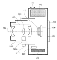
図1において、101はデジタルカメラ等の撮像装置(以下カメラと称する)、102は撮影レンズである撮像光学系、103は撮像光学系102に配置された手振れ補正レンズ、104は撮像光学系の光軸、105はレンズ鏡筒を示す。また、106は撮像素子、107はコンパクトフラッシュ(登録商標)のような外部メモリ(メディア)を示す。また、108は手振れを検出するジャイロセンサによって構成される手振れ検出センサ、109aは手振れ補正レンズ103を駆動する駆動部、110は電源、111はレリーズボタンを示す。
In FIG. 1, 101 is an imaging device such as a digital camera (hereinafter referred to as a camera), 102 is an imaging optical system that is a photographing lens, 103 is a camera shake correction lens disposed in the imaging
カメラ101は、撮像光学系102と不図示のピント調整部を用いて、被写体像を撮像素子106近傍に結像させる。また撮像素子106の前面には、撮像素子106と人間の視感度を概略一致させるための赤外吸収フィルタ、偽色防止のためのローパスフィルタを一体化させたフィルタ112が配置されている。このフィルタ112にゴミ等の異物が付着すると、撮像素子106で得られる画像に影として写り込む。
The
撮像素子106は、撮像光学系102により結像された被写体像を光電変換する。そして、ユーザーによるレリーズボタン111の操作と同期させて、撮像素子106から画像信号を取得し、外部メモリ107へ記録する。また、手振れ補正を実行するモードの場合には、露光中に手振れ検出センサ108の信号に基づいて、駆動部109aが手振れ補正レンズ103を駆動することによって、手振れによる画像のズレを補正する。また本撮影前のフレーミング中は撮像素子106の連続間引き読み出しにより、TFT液晶である表示部210に撮影被写界像をリアルタイムで表示している。なお、手振れ補正動作の有効/無効を、スイッチ211により設定することが可能である。また、スイッチ211は、本実施形態の特徴部分であるフィルタ112に付着した異物を目立たなくするために、手振れ補正レンズ103を駆動させることで撮影画面を移動させる画面移動動作の有効/無効も設定可能である。
The
図2は、カメラ101の電気的構成を示すブロック図である。
FIG. 2 is a block diagram illustrating an electrical configuration of the
図2において、カメラ101は、例えば、撮像系、画像処理系、記録再生系、制御系を備えて構成される。
In FIG. 2, the
撮像系は、例えば、撮像光学系102及び撮像素子106を含む。画像処理系は、例えば、A/D変換器201、画像処理回路202を含む。記録再生系は、例えば、記録処理回路203、外部メモリ107を含む。
The imaging system includes, for example, an imaging
制御系は、例えば、カメラシステム制御回路205、AF(オートフォーカス)センサ206、AE(自動露出)センサ207、手振れ検出センサ108、操作検出回路208、及びレンズシステム制御回路209を含む。また、手振れ補正レンズ103の位置を検出する位置検出センサ204も備えている。なお、レンズシステム制御回路209には、手振れ補正レンズ103を駆動する駆動部109aが備えられている。
The control system includes, for example, a camera
撮像系は、物体からの光を撮像光学系102を介して撮像素子106の撮像面に結像する光学処理系であり、AEセンサ207の信号に基づいて、図示しない絞りなどを用いて、適切な光量の被写体光を撮像素子106に露光する。画像処理回路202は、A/D変換器201を介して、撮像素子106から受けた撮像素子106の画素数に対応する画像信号を処理する信号処理回路であり、ホワイトバランス回路、ガンマ補正回路、補間演算による高解像度化を行う補間演算回路等を有する。
The imaging system is an optical processing system that forms an image of light from an object on the imaging surface of the
記録処理回路203は、外部メモリ107への画像信号の出力を行うと共に、表示部210に出力する像を生成し、保存する。また、記録処理回路203は、公知の方法を用いて画像や動画の圧縮を行う。
The
制御系のうち、操作検出回路208は、レリーズボタン111等の操作を検出する。カメラシステム制御回路205は、操作検出回路208の検出信号に応答して各部を制御し、撮像の際のタイミング信号などを生成して出力する。AFセンサ206は、撮像装置101のピント状態を検出する。AEセンサ207は、被写体の輝度を検出する。手振れ検出センサ108は、手振れを検出する。レンズシステム制御回路209は、カメラシステム制御回路205の信号に応じて、適切にレンズなどを制御する。また、レンズシステム制御回路209は、内部の駆動部109aを用いて手振れ補正レンズ103を駆動する。
In the control system, the
制御系は、外部操作に応答して、撮像系、画像処理系、記録再生系をそれぞれ制御する。例えば、レリーズボタン111の押下を検出して、撮像素子106の駆動、画像処理回路202の動作、記録処理回路203での圧縮処理などを制御する。更に、表示部210によって光学ファインダー、液晶モニタ等に情報の表示を行う情報表示装置の各セグメントの状態を制御する。
The control system controls the imaging system, the image processing system, and the recording / reproducing system in response to an external operation. For example, pressing of the
カメラシステム制御回路205には、AFセンサ206とAEセンサ207が接続されており、これらの信号を元にレンズ、絞りを適切に制御する。カメラシステム制御回路205には、手振れ検出センサ108が接続され、スイッチ211で手振れ補正を行うモードが設定されると、この手振れ検出センサ108の信号とカメラシステム制御回路205の算出結果に基づいて、駆動部109aが手振れ補正レンズ103を駆動する。なお、スイッチ211の設定は、レンズシステム制御回路209を介して、カメラシステム制御回路205に通知される。またカメラシステム制御回路205は、カメラの各種制御パラメータの保持、または画像データの一次保管場所としての内部メモリ212を有している。
An
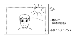
図3A乃至図3Cは、本実施形態の特徴である撮影画面に写り込んでしまう撮像素子近傍に存在する異物の影を、撮影画面の目立たない領域に移動させる画面移動動作(構図変更動作)を示す図である。 3A to 3C show a screen moving operation (composition changing operation) for moving the shadow of a foreign object existing in the vicinity of the image sensor that appears in the imaging screen, which is a feature of the present embodiment, to an inconspicuous area of the imaging screen. FIG.
図3Aにおいては、撮像素子106の前面にあるフィルタ112上に大きな異物200が付着しており、そのままでは主被写体上に異物の影がかかっているため、写真の品位として非常に好ましくない。そこで撮像素子106での異物200の影像の座標G1(x1,y1)を撮影被写界像の中で影の目立たない座標位置に移動させることで、写真の品位を向上させることが可能となる。影の像を移動させるには、撮像光学系102の手振れ補正レンズ103を駆動部109aによりXY方向に移動させたり、あるいは撮像素子106そのものをXY方向に移動させる。これにより、撮影被写界像と撮像素子106の相対位置関係を変位させることができる。
In FIG. 3A, a large foreign matter 200 is attached on the
影の像の移動先としては、図3Aの移動先座標G2(x2、y2)に示したように、影の座標に近い人物の髪の毛など比較的輝度の低い領域に移動させるのが有効である。手振れ補正レンズ103を動作させ、画面移動動作を実行した後の撮影構図を図3Bに示す。ただし手振れ補正レンズ等の可動範囲の問題や、主被写体と画面全体の関係が変化しないように、極力画面移動量は少なくなるのが望ましい。
As the destination of the shadow image, it is effective to move it to a relatively low-luminance region such as the hair of a person close to the shadow coordinates, as indicated by the destination coordinates G2 (x2, y2) in FIG. 3A. . FIG. 3B shows a shooting composition after operating the camera
なお、図3A中の異物の大きさ、位置、さらに異物の撮像素子106に写った影の暗さについての情報である異物情報は後述する異物情報検出処理(異物によって画像不良が生じている画素位置の検出処理)によって撮影者が任意の機会で取得することができる。そして、異物情報は、実際に被写界を撮影する以前にカメラの内部メモリ212に保存され、必要に応じて随時読み出し可能となっている。
In FIG. 3A, the foreign substance information, which is information about the size and position of the foreign substance, and the darkness of the shadow reflected on the
ここで、本実施形態におけるカメラの撮像動作について図4を用いて説明する。図4は本実施形態における撮像動作のフローチャートである。図4における各ステップを順に追って撮像動作を説明する。なお、ユーザーの設定によって手振れ補正動作の実行/不実行、さらには本実施形態の特徴的な動作である撮影画面に写り込んでしまう異物を撮影画面の目立たない領域に移動させる画面移動動作の実行/不実行がスイッチ211にて選択可能であるものとする。
Here, the imaging operation of the camera in the present embodiment will be described with reference to FIG. FIG. 4 is a flowchart of the imaging operation in the present embodiment. The imaging operation will be described in the order of each step in FIG. Execution / non-execution of camera shake correction operation according to user settings, and execution of screen movement operation that moves foreign objects that appear on the imaging screen, which is a characteristic operation of this embodiment, to an inconspicuous area of the imaging screen It is assumed that non-execution can be selected by the
つまりモードの種類としては、(1)手振れ補正有り、かつ画面移動無し、(2)手振れ補正有り、かつ画面移動有り、(3)手振れ補正無し、かつ画面移動有り、(4)手振れ補正無し、かつ画面移動無し、の4つのモードがある。 In other words, the types of modes are (1) camera shake correction and no screen movement, (2) camera shake correction and screen movement, (3) camera shake correction and screen movement, (4) camera shake correction, There are four modes: no screen movement.
ステップS500にてレリーズボタン111の半押下げ操作によって発生する撮影準備動作開始信号(SW1−ON)をカメラシステム制御回路205が受け取ると、ステップS501にて手振れ補正モードに設定されているか否かの判定が行われる。手振れ補正を実行する場合(ステップS501で「YES」)、ステップS502において、通常の手振れ補正用の目標値、すなわち移動目標量:300aを算出する。
When the camera
次に異物を目立たなくするための画面移動モードに設定されているか否かの判定がステップS503でなされる。ここで画面移動モードが設定されていなければ、再度ステップS504にて手振れ補正モードに設定されているか否かの判定が行われる。そして、手振れ補正モードであることが確認されると、移動目標量:300aに基づいて手振れ補正レンズ103を駆動し(ステップS505)、手振れ補正をした状態でライブビューシーケンスを実行する(ステップS509〜ステップS514)。
Next, in step S503, it is determined whether or not the screen movement mode for making the foreign matter inconspicuous is set. If the screen movement mode is not set here, it is determined again in step S504 whether or not the camera shake correction mode is set. When it is confirmed that the camera shake correction mode is set, the camera
ステップS501で手振れ補正を行わない場合(ステップS501で「NO」)も、ステップS503にて画面移動モードで無い場合(ステップS503で「YES」)には、ステップS505の補正レンズ駆動をせずに以下ライブビューシーケンスに移行する。 If camera shake correction is not performed in step S501 ("NO" in step S501), or if the screen movement mode is not selected in step S503 ("YES" in step S503), the correction lens is not driven in step S505. The following shifts to the live view sequence.
ステップS509以降のライブビューシーケンスでは、まずステップS509でAF/AE動作を行う。具体的には、AFセンサ206、AEセンサ207から得られた信号に基づき、カメラシステム制御回路205がレンズシステム制御回路209等を介して焦点合わせ、絞り調整及び露光時間設定を行う。そして、ステップS510で撮像素子106に被写体像が露光され、その後、光電変換された画像信号を撮像素子106から読み出し、A/D変換器201でA/D変換されたデジタル信号を、ステップS511で画像処理回路202により画像処理する。具体的には、公知のγ補正、ホワイトバランス補正、圧縮処理等の画像処理を施し、内部メモリ212を介して表示部210に撮影画像の表示を行う(ステップS512)。
In the live view sequence after step S509, the AF / AE operation is first performed in step S509. Specifically, based on signals obtained from the
次にカメラは、ステップS513にて、SW1−ONの信号を確認し、SW1−ON信号が途切れた場合(ステップS513で「NO」)は、ステップS500に戻って、再びSW1−ON信号が発生するまで待機する。 Next, in step S513, the camera checks the SW1-ON signal. If the SW1-ON signal is interrupted ("NO" in step S513), the camera returns to step S500 and generates the SW1-ON signal again. Wait until
実際にはここで行われているのは、撮影者が本撮影の前に撮影構図を決めるための被写界像を提供するために、表示部210に撮影画面表示を行うための動作である。撮像素子106の撮像信号は読み出し画素の間引き処理を行うことで、後述の本撮影時に比べ扱う画像情報が少ないために、表示部210では60フレーム/秒の高速リフレッシュレートでの本撮影前の被写界像のリアルタイム表示が可能となっている。所謂これがライブビュー表示である。
Actually, what is performed here is an operation for displaying a shooting screen on the
一方、ステップS503に戻って、カメラが画面移動モードに設定されている(ステップS503で「NO」)と、撮像素子上の異物を目立たなくするために撮影画面の移動を行うための画面移動量が算出されているか否かの判定が行われる(ステップS506)。画面移動量の算出法については後述する。 On the other hand, returning to step S503, if the camera is set to the screen movement mode (“NO” in step S503), the screen movement amount for moving the shooting screen to make the foreign matter on the image sensor inconspicuous. Whether or not is calculated is determined (step S506). A method of calculating the screen movement amount will be described later.
ここで画面移動量が算出されていない場合(ステップS506で「NO」)は、画面移動量となるオフセット量301をステップS508にて算出し、再びステップS506に戻る。一方、ステップS506にて画面移動量がステップS508にて既に算出されているのであれば(ステップS506で「YES」)、ステップS502にて算出された手振れ補正のための移動目標量:300aにステップS508で求めたオフセット量301が画面移動量として加算され、最終移動目標量:300bがセットされる(ステップS507)。この最終移動目標量:300bに対してステップS505の手振れ補正レンズ駆動が行われる。ここでステップS501にて手振れ補正モードに設定されていない場合は、移動目標量:300aはセットされていないため、手振れ補正なし、画面移動有りの場合は、手振れ補正レンズ103の最終移動目標量:300bは画面移動量:301に一致する。
If the screen movement amount is not calculated (“NO” in step S506), the offset
以上のことから、カメラはSW1−ON信号を検知している間、手振れ補正、かつ画面移動のために手振れ補正レンズ103を駆動した状態で、表示部210上にこの撮影画面表示を繰り返し行うことが可能となる。
From the above, while the camera detects the SW1-ON signal, the camera screen is repeatedly displayed on the
次に撮影者が表示部210を見て、本静止画撮影をするためにレリーズボタン111をさらに押し下げるとトリガー信号SW2−ONが発生する(ステップS514)。そして、今度は撮像素子106の全画素の露光出力について、前記と同様γ補正、ホワイトバランス補正、圧縮処理等の画像処理を施し、画像ファイルが生成される(ステップS515、S516)。
Next, when the photographer looks at the
そして、ステップS517において、記録処理回路203により、生成した画像ファイルを外部メモリ107に記録し、一連の撮影シーケンスを終了する(ステップS518)。
In step S517, the
また撮影時のF値が小さい(開放に近い)ほど、異物像のぼけ方は大きく目立ちにくくなることが知られているので、画面移動モードにカメラが設定されていても、実際の撮影時の絞りの値が所定値以下であれば、画面移動動作を行わないようにしても良い。例えば絞りの値はF8前後が妥当であり、F8よりも開放側の絞りに設定された絞り優先撮影モード、あるいはマニュアル撮影モードなどでの画面移動動作をこの場合キャンセルする。 In addition, it is known that the smaller the F value at the time of shooting (closer to open), the more blurry the foreign object image becomes, and the less noticeable it is, so even if the camera is set to the screen movement mode, If the aperture value is less than or equal to the predetermined value, the screen moving operation may not be performed. For example, the aperture value before and after F8 is appropriate, and in this case, the screen movement operation in the aperture priority shooting mode or the manual shooting mode set to the aperture closer to F8 is canceled.
ここで、図4のステップS508における、撮像素子上の異物の影を目立たなくするために撮影画面の移動を行う際、画面を移動させる量であるオフセット量301の設定方法について図5、図6A、図6Bを用いて説明する。
Here, in step S508 of FIG. 4, the method of setting the offset
図5において、まずAFセンサ206の出力より主被写体を特定する。AFセンサ206は複数の被写界領域に対して測距情報を得ることができるようになっているため、これら複数の測距情報から公知の近点優先アルゴリズムを用いて撮影すべき主被写体位置を特定できる。また専用のAFセンサを用いなくとも、ライブビュー中の撮像素子106の出力から、被写体の顔の眼球位置を割り出したり、肌色検出を行うことで被写体が人物であれば、その大きさを含めて主被写体を精度良く特定することが可能である(ステップS600)。
In FIG. 5, first, the main subject is specified from the output of the
次に詳細は後述するが、撮影に先立って行われた異物情報検出処理により内部メモリ212に記憶されているカメラの撮像素子近傍に付着している異物の情報(異物補正データ)を読み込む(ステップS601)。ここで、得られた異物の位置座標が主被写体(特に人物の顔)の領域に含まれているか否かの判定がなされる(ステップS602)。そして、異物が主被写体の領域にない、つまり撮影に影響がないと判断された場合(ステップS602で「NO」)は、画面移動を行う対象異物はないということで、ステップS608に進み、終了する。
Next, although details will be described later, information on foreign matter (foreign matter correction data) adhering to the vicinity of the image sensor of the camera stored in the
一方、ステップS602にて異物が主被写体の領域内に存在し、撮影した画像に影響があると判断された場合(ステップS602で「YES」)は、その異物が、画面移動を行う対象異物として特定される。ここで対象となる異物が複数存在する場合は、内部メモリ212から得られた異物情報から各異物の大きさと画素出力落ち込み量(異物像の周辺に対する暗さ)を考慮して、ただ一つを選択する。そして、その撮像素子上の座標系(画素座標)をセットする(ステップS603)。ここでは図6AのG1(x,y1)とする。
On the other hand, if it is determined in step S602 that a foreign object exists in the area of the main subject and the captured image is affected ("YES" in step S602), the foreign object is determined as a target foreign object to be moved. Identified. Here, when there are a plurality of target foreign matters, only one is taken into consideration from the foreign matter information obtained from the
対象となる異物が決定されたら、内部メモリ212から読み出された異物の撮像素子での画素座標より、図6Aに示すように、その画素座標を中心として例えば、撮像素子106の9画素×9画素を一つのブロックとした小領域をさらに15×15のブロックにして撮像素子の画素を分割する(ステップS604)。分割された一つのブロックに属する画素出力は平均化がなされ(ステップS605)、結果的に異物近傍の微細な輝度分布が測定される(被写界分析、輝度分布検出)。
When the target foreign matter is determined, for example, 9 pixels × 9 pixels of the
次に内部メモリ212から得られた異物の大きさ、画素出力落ち込み量から図6Bに示すように、異物の半径が5ピクセル以下で、出力落ち込み量が周辺画素の20カウント以下の場合は、上記15×15ブロックの内、8×8ブロックの領域内で最低輝度となるブロックを選択する(図6Bの領域A)。
Next, as shown in FIG. 6B from the size of the foreign matter and the pixel output drop amount obtained from the
一方、異物の半径が6ピクセル以上で、出力落ち込み量が周辺画素の21カウント以上(8ビット処理で最大255カウント)の場合は、15ブロック全て(図6Bの領域Aと領域B)の中から最低輝度のブロックを選択する(ステップS606)。 On the other hand, when the radius of the foreign object is 6 pixels or more and the output drop amount is 21 counts or more of the surrounding pixels (maximum 255 counts in 8-bit processing), all 15 blocks (area A and area B in FIG. 6B) A block having the lowest luminance is selected (step S606).
これは撮影を行った際、より目立つ異物は、最終的に画面を移動する距離が大きくなっても輝度比較する領域を広げ、できるだけ被写界輝度の低い領域に移動させることで異物の影を目立たせなくするためである。ここで選択されたブロックの中心座標が画面移動をするための移動先座標となる図6AのG2(x2,y2)である。次に画面移動をするためのオフセット量301:δは、異物座標位置G1(x1,y1)と画面移動先座標G2(x2,y2)より、以下の式から求めることができる。 This is because when the image is taken, the more noticeable foreign matter will expand the area to compare the brightness even if the distance to move the screen eventually becomes large, and the shadow of the foreign object will be moved by moving it to an area with as low a field luminance as possible. This is to make it inconspicuous. The center coordinates of the selected block are G2 (x2, y2) in FIG. 6A, which is the movement destination coordinates for moving the screen. Next, the offset amount 301: δ for moving the screen can be obtained from the following expression from the foreign object coordinate position G1 (x1, y1) and the screen movement destination coordinate G2 (x2, y2).
δ=√{(x2−x1)2+(y2−y1)2}
ただし、実際の手振れ補正、画面移動の動作制御は、後述のごとく光軸104に対して垂直な面内のx、yの2軸で手振れ補正レンズ103を移動させることによって行われるため、δx=x2−x1、δy=y2−y1が実際の制御量となる。
δ = √ {(x2−x1) 2 + (y2−y1) 2 }
However, since actual camera shake correction and screen movement operation control are performed by moving the camera
図7は、本実施形態のカメラにおける異物検出処理(異物によって画像不良が生じている画素位置の検出処理)を説明するフローチャートである。この処理は、カメラシステム制御回路205が内部メモリ212に記憶された異物検出処理プログラムを実行することにより実施され、撮影者が被写界の本撮影を行う以前に実行しておく必要がある。
FIG. 7 is a flowchart for explaining foreign matter detection processing (detection processing of a pixel position where an image defect is caused by a foreign matter) in the camera of this embodiment. This processing is performed by the camera
この異物検出処理は、異物検出用画像を取得することにより行われる。異物検出処理を行う場合、面光源装置の出射面や白い壁などの均一な色を持つ面に撮像光学系102の光軸104を向けてカメラを設置し、異物検出用画像の撮影準備を行う。または撮像光学系(撮影レンズ)102先端のフィルタ着脱のためのマウント部(不図示)に異物検出用のライトユニット(小型の光源装置)を装着し、異物検出用画像の撮影準備を行う。ライトユニットの光源は例えば白色LEDが考えられ、発光面のサイズを予め定めた絞り値(例えば、本実施形態ではF32)相当になるように調整するのが望ましい。
This foreign object detection process is performed by acquiring a foreign object detection image. When performing foreign object detection processing, a camera is installed with the
準備が終了した後、異物検出処理の開始が指示されると、カメラシステム制御回路205は、まず絞りの設定を行う。撮像素子近傍の異物はレンズの絞り値によって結像状態が変わり、レンズの瞳位置によって位置が変化する。したがって、異物補正データには異物の位置や大きさに加え、異物検出用画像の撮影時の絞り値とレンズの瞳位置を保持する必要がある。
When the start of foreign object detection processing is instructed after the preparation is completed, the camera
ただし、異物補正データを作成する段階で、常に同じ絞り値を使うことを予め決めておけば、必ずしも異物補正データ内に絞り値を保持する必要はない。また、瞳位置に関してもライトユニットを用いたりすることで、同様に必ずしも異物補正データ内に瞳位置を保持する必要はなくなる。 However, if it is determined in advance that the same aperture value is always used at the stage of creating the foreign matter correction data, it is not always necessary to hold the aperture value in the foreign matter correction data. Similarly, by using a light unit for the pupil position, it is not always necessary to hold the pupil position in the foreign substance correction data.
つまり、異物補正データを作成する段階において、絞り込む絞り値を適宜変更する場合には、検出時の絞り値とレンズの瞳位置を、異物補正データ内に保持する必要があると言える。なお、ここで瞳位置とは、射出瞳の撮像面(焦点面)からの距離をいう。 That is, when the aperture value to be narrowed down is appropriately changed at the stage of creating the foreign matter correction data, it can be said that the aperture value at the time of detection and the pupil position of the lens need to be held in the foreign matter correction data. Here, the pupil position refers to the distance from the imaging plane (focal plane) of the exit pupil.
ここでは、例えばF32を指定する(ステップS701)。 Here, for example, F32 is designated (step S701).
次にカメラシステム制御回路205は、レンズシステム制御回路209に対し、撮像光学系(撮影レンズ)102の絞り羽根制御を行わせ、ステップS701で指定された絞り値に絞りを設定する(ステップS702)。さらに、フォーカス位置を無限遠に設定する(ステップS703)。
Next, the camera
撮影レンズの絞り値とフォーカス位置が設定されると、異物検出モードでの撮影を実行する(ステップS704)。ステップS704で行う撮像処理ルーチンの詳細に関しては図4を用いた説明に準じる。撮影された画像データは、内部メモリ212に格納される。
When the aperture value and focus position of the photographing lens are set, photographing in the foreign object detection mode is executed (step S704). Details of the imaging processing routine performed in step S704 are the same as those described with reference to FIG. The captured image data is stored in the
撮影が終了すると、撮影時の絞り値とレンズ瞳位置を取得する(ステップS705)。 When shooting is completed, the aperture value and lens pupil position at the time of shooting are acquired (step S705).
画像処理回路202は内部メモリ212に記憶されている撮影画像の各画素に対応するデータを呼び出す(ステップS706)。次に画像処理回路202は、後述する図8に示す異物領域取得ルーチンを行い、異物が存在する画素の位置と大きさと周辺画素に対する出力の落ち込み量を取得する(ステップS707)。
The
ここで図7のステップS707の異物領域取得ルーチンについて図8を用いて説明する。 Here, the foreign substance region acquisition routine in step S707 of FIG. 7 will be described with reference to FIG.
異物検出処理のために取得された画像データはメモリ上に展開され、予め定められたブロック単位で処理が行われる。 The image data acquired for the foreign object detection process is developed on the memory and processed in units of predetermined blocks.
ブロック内の異物領域判定は、図8に示す流れで行う。まずブロック内の最大輝度Lmax、平均輝度Laveを算出し、次式を用いてブロック内のスレッショルド値T1を算出する。 The foreign substance area determination in the block is performed according to the flow shown in FIG. First, the maximum luminance Lmax and average luminance Lave in the block are calculated, and the threshold value T1 in the block is calculated using the following equation.
T1=Lave×0.6+Lmax×0.4
次に、スレッショルド値を超えない画素を異物画素とし(ステップS801)、異物画素によって構成される孤立領域を各々一つの異物領域di(i=0,1,…,n)とする(ステップS802)。異物領域は各々異物領域を構成する画素の水平方向の座標の最大値Xmaxおよび最小値Xmin、垂直方向の座標の最大値Ymaxおよび最小値Yminを求め、異物領域diのサイズを表す半径riを次式によって算出する(ステップS803)。
T1 = Lave × 0.6 + Lmax × 0.4
Next, pixels that do not exceed the threshold value are set as foreign pixels (step S801), and isolated regions constituted by the foreign pixels are each set as one foreign region di (i = 0, 1,..., N) (step S802). . For the foreign substance areas, the maximum value Xmax and the minimum value Xmin of the horizontal coordinates of the pixels constituting the foreign substance area are obtained, and the maximum value Ymax and the minimum value Ymin of the vertical coordinates are obtained. Calculation is performed using an equation (step S803).
ri=√{((Xmax−Xmin)/2)2+((Ymax−Ymin)/2)2)
その後ステップS804で、異物領域毎の平均輝度値を算出する。これより異物領域に隣接した領域の輝度との差、つまり異物の出力落ち込み量も算出できる。
ri = √ {((Xmax−Xmin) / 2) 2 + ((Ymax−Ymin) / 2) 2 )
Thereafter, in step S804, an average luminance value for each foreign substance region is calculated. From this, the difference from the brightness of the area adjacent to the foreign object area, that is, the output drop amount of the foreign object can also be calculated.
ここで再び図7に戻って、ステップS707で取得した異物が存在する画素の位置と大きさ、出力値およびステップS705で取得した絞り値とレンズ瞳位置情報を、異物補正データとして内部メモリ212に登録する(ステップS708)。
Returning to FIG. 7 again, the position and size of the pixel where the foreign matter exists acquired in step S707, the output value, and the aperture value and lens pupil position information obtained in step S705 are stored in the
具体的には、検出用画像撮影時のレンズ情報として、検出用画像撮影時における実際の絞り値(F値)と、そのときのレンズ瞳位置を格納する。続く記憶領域に検出した異物領域の数(整数値)を格納し、これに続き、個々の具体的な異物領域のパラメータを、異物領域の数だけ繰返して格納する。異物領域のパラメータは、異物の半径、周辺画素に対する出力の落ち込み量、有効画像領域における中心のx座標、おなじく中心のy座標、以上4つの数値がセットとなって登録される。 Specifically, the actual aperture value (F value) at the time of detection image capture and the lens pupil position at that time are stored as lens information at the time of detection image capture. The number of detected foreign substance areas (integer value) is stored in the subsequent storage area, and subsequently, specific parameters of the specific foreign substance areas are repeatedly stored by the number of foreign substance areas. As the parameters of the foreign matter area, the radius of the foreign matter, the amount of output drop with respect to surrounding pixels, the x coordinate of the center in the effective image region, the y coordinate of the same center, and the above four numerical values are registered as a set.
ここでステップS708において、予め画素欠陥位置情報として内部メモリ212に記録されている製造時からの不良画素(画素欠陥)の位置と、読み出した画素データの位置を比べて画素欠陥であるかどうかを確認する。そして、画素欠陥によるものでは無いと判断された異物領域のみ、異物補正情報として内部メモリ212に情報を登録しても良い。
Here, in step S708, the position of the defective pixel (pixel defect) from the time of manufacture recorded in advance in the
またこの異物補正情報は、通常撮影時に画像データの撮影時情報と共に画像に付加して外部メモリ107に記録することで、後述の第2の実施形態にて説明する異物除去処理時に利用することができる。
Further, this foreign matter correction information is added to the image together with the photographing time information of the image data during normal photographing and recorded in the
次に、手振れ補正システムについて、図9及び図10を用いて詳細に説明する。 Next, the camera shake correction system will be described in detail with reference to FIGS.
手振れ補正系の制御ブロックは、図9に示すように構成されている。手振れ検出センサ108で検出された手振れ信号は、所定の周波数以上の信号を通過させるハイパスフィルタ(HPF)302を通過した後、積分器303により振れ量に換算される。そして、この換算された振れ量に、手振れ補正レンズ103の位置を検出する位置検出センサ204の検出信号が、算出部212において加味され、第1の移動目標量300aが生成される。通常の手振れ補正制御であれば、この第1の移動目標量300aに基づいて駆動部109aを制御し、手振れ補正レンズ103を駆動することによって、ユーザーの手振れを相殺する。本実施形態においては、更に、外部メモリ107に格納されたオフセット量301が読み出され、第1の移動目標量300aに加算されて第2の移動目標量300bが生成される。そして、この第2の移動目標量300bに従って、駆動部109aを制御し、手振れ補正レンズ103を駆動する。またハイパスフィルタ302および積分器303はカメラシステム制御回路205に内蔵されている。
The control block of the camera shake correction system is configured as shown in FIG. A camera shake signal detected by the camera
上記の説明においては、手振れ補正レンズ103の移動方向につき1軸を対象に1系統分説明したが、実際には手振れ補正レンズ103は、光軸104に対して垂直な面内で移動する。従って、平面内の2軸で移動させるためには2系統分必要となり、本実施形態においても2系統有するものとする。
In the above description, one system has been described for one axis with respect to the movement direction of the camera
図10は、図9のフィードバック制御系による手振れ補正レンズ103の動作を概略的に説明するための図である。
FIG. 10 is a diagram for schematically explaining the operation of the camera
横軸は時間の経過を表し、縦軸は手振れ補正レンズ103の光軸中心からの偏心量を表す。実線は、被写体像が撮像素子106上で振れることなく、光軸104を中心として結像するように、ユーザーの手振れに応答して、手振れ補正レンズ103を駆動した場合を表す。すなわち、通常の手振れ補正制御による駆動であり、第1の移動目標量300aに基づいて駆動部109aを制御したときの状態を示したものである。これに対し本実施形態においては、点線のように手振れ補正レンズ103を駆動する。具体的には第1の移動目標量300aに、画面移動のためのオフセット量301を加算することで最終目標量300bを得る。なお、このオフセット量301は、図9では被写体像を上方に所定量ずらすものであるが、実際には平面内で上下方向と左右方向が各々制御される。このオフセット量301を与えて、手振れ補正レンズ103を駆動した場合、被写体像が撮像素子106上で振れることなく、光軸104よりオフセット量に応じた分だけずれて結像する。従って、撮像素子106からは、オフセット量301に応じた分だけ画角のずれた、手振れのない画像信号を得ることができる。
The horizontal axis represents the passage of time, and the vertical axis represents the amount of eccentricity of the camera
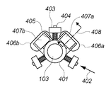
次に、手振れ補正レンズ103を駆動する機構について図11A〜図11Cを用いて説明する。図11A〜図11Cは、撮像光学系102の一部の光学系である手振れ補正レンズ103を移動させる機構を概略的に示す図である。
Next, a mechanism for driving the camera
図11Aにおいて、401はレンズを保持する可動枠、103は手振れ補正レンズ、403は鏡筒に取り付けられた固定部、404は可動枠401上の支持/案内部、405は支持/案内部404と同軸に取り付けられたバネを示す。また、406a,406bは固定部403に取り付けられたコイル、407a,407bは可動枠401に取り付けられたマグネットを示す。
In FIG. 11A, 401 is a movable frame for holding a lens, 103 is a camera shake correction lens, 403 is a fixed portion attached to the lens barrel, 404 is a support / guide portion on the
図11Bは図11Aに示した手振れ補正機構の右側面図である。図11Bにおいて、410、412は図11Aには図示されていないヨークである。411は図11Aには図示されていない可動部の位置検出センサである。具体的にはホール素子により構成される。
FIG. 11B is a right side view of the camera shake correction mechanism shown in FIG. 11A. In FIG. 11B,
図11Cは、図11Aの矢印402の方向から見た図である。可動枠401は支持/案内部404によって固定部403に対して平面運動可能に案内支持されている。図11Cでは、長円形の案内溝413の中に円形の支持/案内部404が挿入されている。手振れ補正機構は、3箇所とも同一の構造とすることによって、撮像光学系102の光軸104の方向には拘束され、光軸104に直行する平面上では運動させることができる。可動枠401上には、手振れ補正レンズ103及び駆動用のマグネット407a,407bが取り付けられている。また、可動枠401は支持/案内部404と同軸に取り付けられたバネ405によって弾性支持されており、駆動力が発生していないときは手振れ補正レンズ103の中心が光軸104にほぼ一致するように配置されている。駆動部分は図11Bに示すようにマグネット407aの両側をヨークで挟み込み、片側にコイル406aを備えた構成をしている。駆動部分の原理は図12A、12Bを用いて説明する。
FIG. 11C is a view seen from the direction of the
図12A、12Bは、図11Aに示す点線408を断面として駆動回路部分を抜粋した矢視図である。
12A and 12B are arrow views extracted from the drive circuit portion with the dotted
駆動用マグネット407aは2極で厚み方向に着磁されている。更に、マグネット407aの着磁方向の両側にはヨーク410、412が設けられており、多くの磁束は外に漏れることなく、図12Aの図中に示すような矢印方向の磁界を発生させている。この状態でコイル406aに通電すると、コイル406a上の領域501と502には、それぞれ反対方向の電流が流れる。一方、磁界の方向も反対であるため、フレミングの左手の法則によって同一方向の力が発生する。このときコイルが固定されているため、作用反作用の法則によって可動部に取り付けられたマグネット407aが力を受けて駆動される。駆動力はコイル406aの電流に比例し、コイル406aに流す電流の向きを反対方向にすることによって、マグネット407aが受ける駆動力も反対にすることができる。駆動力が発生すると、可動枠401がバネ405によって弾性支持されているので、バネ力と釣り合う点まで変位する。つまり、コイル406aの電流を適切に制御することによって、可動枠401の位置を制御することができる。更に、ヨーク410上にはホール素子411が取り付けられており、図12Bに示すように、コイル406aに電流を印加することにより発生した駆動力によってマグネット407aが変位すると、ホール素子411上の磁気バランスも変化する。そのため、ホール素子411の信号を得ることによって、マグネット407aの位置を検出することが可能となる。
The
図11A〜図11C、図12A及び12Bでは、可動部にマグネットが配置され、固定部にコイルが配置されたムービングマグネット方式での実施形態を例示した。しかしながら、本発明は、可動部にコイルが配置され、固定部にマグネットが配置されたムービングコイルやその他の駆動方法を用いた手振れ補正機構を備えた撮像装置についても適用可能である。 11A to 11C and FIGS. 12A and 12B exemplify an embodiment using a moving magnet system in which a magnet is arranged in the movable part and a coil is arranged in the fixed part. However, the present invention is also applicable to an imaging apparatus including a moving coil in which a coil is disposed in a movable part and a magnet is disposed in a fixed part, and a camera shake correction mechanism using other driving methods.
続いて、上記撮影レンズの一部である手振れ補正レンズ103を動かす手振れ補正システムとは異なり、撮像素子106そのものを動かす(シフトさせる)ことによって手振れ補正を行うシステムについても説明を行う。
Subsequently, unlike a camera shake correction system that moves the camera
図13は本実施形態の撮像素子周辺の構造を示す図であり、手振れ補正のための駆動部109bを撮像素子106の近傍に備えている。駆動部109bは撮像素子106をシフト駆動する。これに伴い、手振れ補正をするモードの有効/無効、および異物補正を有効とするか否かの設定を行うスイッチ211は、撮像装置101側に設けられている。その他の構成は、前述した手振れ補正レンズによる手振れ補正形態と同様である。
FIG. 13 is a diagram showing the structure around the image sensor according to the present embodiment, and includes a drive unit 109b for camera shake correction in the vicinity of the
図13及び図14は、撮像素子106をシフト駆動する機構の例を示す図である。
FIG. 13 and FIG. 14 are diagrams illustrating an example of a mechanism that shift-drives the
図13において、106は撮像素子、1101,1102は駆動コイル、1103,1104は可動部の位置検出を行うホール素子、1105,1106,1107,1108はマグネットを示す。また、1109は第1の保持部、1110は第1の保持部1109上に設けられた第1の案内部、1111は第2の保持部、1112は第2の保持部1111上に設けられた第2の案内部、1113は鏡筒に固定される第3の保持部を示す。また、1114は第1の保持部1109と図示しない固定部との間に設けられた第1の弾性体、1115は第2の保持部1111と図示しない固定部との間に設けられた第2の弾性体を示す。第1の案内部1110と第2の案内部1112が案内する方向は互いに直交している。また、撮像素子106を備えた第1の保持部1109は第1の弾性体1114及び第2の弾性体1115によって弾性支持されている。
In FIG. 13, 106 is an image sensor, 1101 and 1102 are drive coils, 1103 and 1104 are Hall elements for detecting the position of the movable part, and 1105, 1106, 1107 and 1108 are magnets.
図14は駆動部の構成を示す図である。磁気回路は2つ存在するが90度角度が異なるだけで同様の構成となっているので、駆動コイル1101及びマグネット1105,1106によって構成される駆動部を用いて説明を行う。
FIG. 14 is a diagram showing the configuration of the drive unit. Although there are two magnetic circuits, the configuration is the same except that the angle is different by 90 degrees. Therefore, description will be made using a drive unit constituted by a
図14において、1203は磁束を模式的に示した矢印であり、閉磁路を示す。1201,1202は図13には図示しないヨークである。マグネット1105,1106は2つの領域に分割して着磁されている。そのため図14に示したように磁束の多くは背面のヨーク1201,1202を使って循環する閉磁路1203を構成する。駆動コイル1101に電流が流れることによって、フレミングの左手の法則に従って駆動コイル1101に対して力が発生する。発生した力と第1の弾性体1114及び第2の弾性体1115とのつりあいによって第1の保持部1109及び撮像素子106は変位する。第1の保持部1109が変位することによって、第1の保持部1109上に設けられたホール素子1103,1104も変位する。結果として、固定部に設けられた磁気回路に対して相対的に変位するので、ホール素子1103,1104の信号から第1の保持部1109の位置が検出可能であり、フィードバック制御を行うことができる。更に、露光中においては、レンズ情報と手振れ検出センサ108の信号に基づいて、適切に駆動コイル1101及び1102の電流を制御することによって、振れの少ない高品位な画像を得ることができる。
In FIG. 14,
撮像素子の手振れ補正系の制御ブロックは、駆動対象が手振れ補正レンズ103ではなく撮像素子106である点を除いて、前述した手振れ補正レンズ103による手振れ補正形態と同様である。ここでもオフセット量301は、後述するようにカメラシステム制御回路205により適切に設定される。
The control block of the camera shake correction system of the image sensor is the same as the camera shake correction mode by the camera
前述した手振れ補正レンズ103による手振れ補正形態においても、オフセット量の設定については、撮像素子の手振れ補正系の実施形態で説明した方法と同様の考え方が適用できる。撮像素子の手振れ補正系では、撮像素子106をシフト駆動するため、結像する被写体像換算(撮像素子106上)でのオフセット量を算出した。手振れ補正レンズ103による手振れ補正形態であっても、手振れ補正レンズ103を駆動するため、撮像素子106上での移動距離となるような、手振れ補正レンズ103のオフセット量を光学的倍率から算出して用いれば良い。
Also in the above-described camera shake correction mode using the camera
(第2の実施形態)
撮影画面に写り込んでしまう撮像素子106近傍に存在する異物の影を、手振れ補正動作を利用した画面移動動作によって、撮影画面の目立たない被写界像領域に移動させることで撮影画像の品位を向上させる手法を説明したものが、第1の実施形態であった。
(Second Embodiment)
The quality of the captured image is improved by moving the shadow of a foreign object existing in the vicinity of the
この第2の実施形態は、異物の影を画面移動動作によって、被写界像に対して均一な画像出力を発生する画素領域に移動させた後に撮影を行い、その撮影された画像上の異物の影を後処理の画像処理により修正を行うものである。 In the second embodiment, the shadow of a foreign object is moved to a pixel area that generates a uniform image output with respect to the object scene image by a screen movement operation, and the foreign object on the captured image is captured. The shadow is corrected by post-processing image processing.
図3Aにおいて、異物200の影座標に近く、画像出力に均一性のある画素領域、例えば図3Aの背景のG3(x3,y3)の位置まで撮影画面の移動を行ったものが図3Cである。ただしこのままでは異物の影が非常に目立つ撮影結果となってしまう。しかしながら異物の影に相等する画素出力に対して、その異物の影に相等する画素に隣接する周辺画素の出力は均一な出力となっているために、後述する画像出力の補間処理を行うことで、精度良く異物の影を消すことができるようになる。 In FIG. 3A, FIG. 3C shows the image screen moved to a pixel area close to the shadow coordinates of the foreign object 200 and uniform in image output, for example, the position of G3 (x3, y3) in the background of FIG. 3A. . However, if the image is left as it is, the result of the photographing is that the shadow of the foreign object is very noticeable. However, since the output of the peripheral pixels adjacent to the pixel equivalent to the shadow of the foreign object is uniform with respect to the pixel output equivalent to the shadow of the foreign object, interpolation processing of the image output described later is performed. The shadow of foreign matter can be erased with high accuracy.
撮像素子106上の異物の影を被写界像に対して均一な画像出力を発生する画素領域へ移動させる際、画面を移動させる量であるオフセット量301の設定方法については図5および図6A、図6Bを用いた説明に準じる。つまり移動すべき一個の異物の影座標を特定した後、その座標近傍の画素をブロック化し、ブロック内の画素を平均化することでブロックの輝度とする。得られた複数のブロック輝度データの相関と、異物の影の大きさから、最も異物座標に近く、均一輝度で所定数からなるブロックの中心座標を決定し、それを異物移動先の座標とすれば良い。例えば半径5画素以上の大きい異物であれば、ブロック輝度差が2カウント以内の均一ブロックで少なくとも3×3の大きさのブロックが存在する最も異物座標に近い領域を選択する。一方、異物半径4画素以下であれば2×2のブロック領域を選択することになり、各々複数ブロックからなる領域の中心座標である手振れ補正システムで移動すべき画面移動先座標は、G3(x3,y3)となる。従って画面移動動作を行うためのオフセット量301:δは、異物座標位置G1(x1,y1)と画面移動先座標G3(x3,y3)から、次式で求めることができる。
5 and 6A show how to set the offset
δ=√{(x3−x1)2+(y3−y1)2}
ここで前述のごとく、光軸104に対して垂直な面内のx、yの2軸で手振れ補正レンズ103を移動させるため、δx=x3−x1,δy=y3−y1が実際の画面移動の制御量となる。
δ = √ {(x3-x1) 2 + (y3-y1) 2 }
Here, as described above, since the camera
なお、本実施形態に係るカメラの撮像動作は、第1の実施形態で図4を用いて説明した動作と同様である。 Note that the imaging operation of the camera according to the present embodiment is the same as the operation described with reference to FIG. 4 in the first embodiment.
次に、外部メモリ107に記録された撮影画像に写りこんだ異物の影に対して画像処理を行い影を消す異物除去処理について図15を用いて具体的に説明する。
Next, with reference to FIG. 15, a specific description will be given of foreign matter removal processing for performing image processing on a shadow of a foreign matter reflected in a captured image recorded in the
この異物除去処理は、カメラ本体ではなく、別途用意したパーソナルコンピュータ上で動作する画像処理プログラムを用いて行う場合について説明する。 A description will be given of a case where this foreign matter removal processing is performed using an image processing program that operates on a separately prepared personal computer instead of the camera body.
カメラ101から取り外された外部メモリ107から異物補正データが添付された通常撮影画像データをパーソナルコンピュータに取り込んで、パーソナルコンピュータの一次記憶部に記憶する(ステップS900)。次に、通常撮影された画像データ(異物除去処理を行う対象となる画像)から、撮影画像に付与された異物補正データを抽出する(ステップS901)。
Normal photographed image data attached with foreign substance correction data is taken into the personal computer from the
次に、ステップS901で抽出した異物補正データから異物の座標列Di(i=1,2,…n)、異物の大きさである半径列Ri(i=1,2,…,n)、絞り値F1とレンズ瞳位置L1を得る(ステップS902)。 Next, the foreign substance coordinate sequence Di (i = 1, 2,... N) from the foreign substance correction data extracted in step S901, the radius series Ri (i = 1, 2,. A value F1 and a lens pupil position L1 are obtained (step S902).
ステップS903で、通常撮影された画像の撮影時の絞り値F2とレンズ瞳位置L2を取得し、ステップS904で座標Diを次式で変換する。ここで、dは画像中心から座標Diまでの距離、Hは撮像素子106の表面と異物との距離であるとする。変換後の座標Di’と変換後の半径Ri’は次のように表わされる。
In step S903, an aperture value F2 and a lens pupil position L2 at the time of shooting of a normally shot image are acquired, and in step S904, coordinates Di are converted by the following equation. Here, d is a distance from the center of the image to the coordinates Di, and H is a distance between the surface of the
Di’(x,y)=(L2×(L1−H)×d/((L2−H)×L1))×Di(x,y)
Ri’=(Ri×F1/F2+3)× 2
ここでの単位はピクセルであり、Ri’についての「+3」はマージン量である。2倍しているのは、平均輝度を用いて異物領域を検出するため、異物領域外の領域が必要であるからである。
Di ′ (x, y) = (L2 × (L1−H) × d / ((L2−H) × L1)) × Di (x, y)
Ri ′ = (Ri × F1 / F2 + 3) × 2
The unit here is a pixel, and “+3” for Ri ′ is a margin amount. The reason for doubling is that an area outside the foreign substance area is necessary to detect the foreign substance area using the average luminance.
ステップS905で、補間処理カウンタiを0に初期化し、ステップS906でiをカウントアップする。 In step S905, the interpolation processing counter i is initialized to 0, and i is incremented in step S906.
ステップS907でi番目の座標Di’、半径Ri’によって表される領域に対して後述する補間ルーチンを実行し、領域内の異物を除去する。ステップS908で全ての座標について異物除去処理を適用したかどうかを判定し、全ての座標について処理が終わっていれば処理を終了し、そうでなければステップS906に戻る。 In step S907, an interpolation routine described later is executed on the area represented by the i-th coordinate Di 'and radius Ri' to remove foreign matter in the area. In step S908, it is determined whether the foreign matter removal process has been applied to all coordinates. If the process has been completed for all coordinates, the process ends. If not, the process returns to step S906.
ここで、リペア処理を用いて実行する補間ルーチンについて説明する。 Here, an interpolation routine executed using the repair process will be described.
リペア処理とは、指定された領域内で予め定められた条件に合う孤立領域を検出し、この孤立領域を周囲の画素で補間する処理である。 The repair process is a process of detecting an isolated area that meets a predetermined condition in a specified area and interpolating the isolated area with surrounding pixels.
図16は、補間ルーチンの流れを示すフローチャートである。まずステップS1001で、異物領域判定を行う。ここで、リペア処理の対象となる領域の中心座標をP、半径をRとする。異物領域とは、次の条件全てを満たす領域とする。
(1)リペア処理対象領域に含まれる画素の平均輝度Yaveと最高輝度Ymaxを用いて次式で求められるスレッショルド値T2より暗い領域。
FIG. 16 is a flowchart showing the flow of the interpolation routine. First, in step S1001, foreign object region determination is performed. Here, it is assumed that the center coordinate of the region to be repaired is P and the radius is R. The foreign substance area is an area that satisfies all of the following conditions.
(1) A region that is darker than the threshold value T2 obtained by the following equation using the average luminance Yave and the maximum luminance Ymax of the pixels included in the repair processing target region.
T2=Yave×0.6+Ymax×0.4
(2)上記の中心座標P、半径Rで表される円と接しない領域。
(3)(1)で選択された輝度の低い画素によって構成される孤立領域に対し、図8中のステップS803と同様の方法で算出した半径値がl1画素以上、l2画素未満である領域。
T2 = Yave × 0.6 + Ymax × 0.4
(2) A region not in contact with the circle represented by the center coordinate P and the radius R.
(3) A region in which the radius value calculated by the same method as in step S803 in FIG. 8 is not less than l1 pixels and less than l2 pixels with respect to the isolated region constituted by the low-luminance pixels selected in (1).
本実施形態では、l1は3画素、l2は30画素とする。このようにすることで、孤立した小領域だけを異物領域として扱うことが可能になる。 In this embodiment, l1 is 3 pixels and l2 is 30 pixels. By doing in this way, it becomes possible to treat only an isolated small area as a foreign substance area.
ステップS1002で、このような領域があればステップS1003へ進み、異物領域補間を行い、存在しない場合は処理を終了する。ステップS1103で実行する異物領域補間処理は、公知の欠損領域補間法で行う。公知の欠損領域補間法には例えば、特開2001−223894号公報に開示されているパターン置換がある。特開2001−223894号公報では赤外光を用いて欠損領域を特定しているが、本実施形態ではステップS1001で検出した異物領域を欠損領域として扱い、パターン置換により異物領域を周囲の正常画素で補間する。パターン置換で埋められない画素については、パターン置換後の画像データに対し、補間対象画素に最も近い順に正常画素をp個、最も遠い順に正常画素をq個選択し、その平均色を用いて補間する。 In step S1002, if there is such an area, the process proceeds to step S1003, foreign object area interpolation is performed, and if it does not exist, the process ends. The foreign substance area interpolation processing executed in step S1103 is performed by a known defect area interpolation method. Known defect area interpolation methods include, for example, pattern replacement disclosed in JP-A-2001-223894. In Japanese Patent Laid-Open No. 2001-223894, a defective area is specified using infrared light. In this embodiment, the foreign substance area detected in step S1001 is treated as a defective area, and the foreign substance area is surrounded by normal pixels by pattern replacement. Interpolate with. For pixels that are not filled by pattern replacement, select p normal pixels in the order closest to the pixel to be interpolated and q normal pixels in the order farthest from the image data after pattern replacement, and use the average color for interpolation. To do.
以上、本実施形態では、一旦カメラによる撮影を行い、保存された撮影画像に対して、例えばパーソナルコンピュータを用いて撮影画像を取り込み、外部プログラムにて画像処理を実施して異物処理を行う形態について説明した。しかし、この画像処理をカメラ内部で行うことも可能である。つまり撮影の本露光後の画像処理中に補間処理を行っても良い。あるいは、本露光、画処理後に一旦外部メモリ107に画像データを記録した後、撮影者が再度画像データを呼び出してから手動で補間処理プログラムを実行するようにしても良い。
As described above, in the present embodiment, with respect to a mode in which a camera image is captured once, and a captured image is captured using a personal computer, for example, and image processing is performed by an external program to perform foreign object processing. explained. However, this image processing can also be performed inside the camera. That is, interpolation processing may be performed during image processing after the main exposure for shooting. Alternatively, after the main exposure and image processing, the image data is once recorded in the
また本実施形態の方法では、画像処理という後処理が発生するが、異物の影の影響をほとんどなくすことが可能である。また異物の影を移動させるべき均一輝度領域が画面上に存在する確率はかなり高いため、異物の影の位置を移動させる量が少なくてすみ、結果的に撮影構図の変化が少なくて済む可能性が高いという利点がある。 In the method of the present embodiment, post-processing called image processing occurs, but it is possible to almost eliminate the influence of foreign object shadows. In addition, there is a high probability that there is a uniform luminance area on the screen to move the shadow of the foreign object, so the amount of movement of the shadow of the foreign object can be reduced, resulting in less change in the shooting composition. There is an advantage that is high.
(第3の実施形態)
上記の第1及び第2の実施形態では、画面移動先座標を撮影画像の輝度分布に着目して決定したが、画像の出力を公知の離散コサイン変換(DCT)を用いて空間周波数分析することで、空間周波数の高い領域座標を画面移動先座標にすることも有効である。具体的には、元画像のRGB各成分について、異物座標近傍を8×8画素ごとの小ブロックに分割し、各小ブロックについてDCT演算を行うことで空間周波数成分が高い領域か、低い領域かの数値化が可能となる(空間周波数分布検出)。
(Third embodiment)
In the first and second embodiments described above, the screen movement destination coordinates are determined by paying attention to the luminance distribution of the captured image, but the output of the image is subjected to spatial frequency analysis using a known discrete cosine transform (DCT). Thus, it is also effective to use region coordinates having a high spatial frequency as screen movement destination coordinates. Specifically, for each RGB component of the original image, the region around the foreign object coordinates is divided into small blocks of 8 × 8 pixels, and a DCT operation is performed on each small block to determine whether the region has a high or low spatial frequency component. Can be quantified (spatial frequency distribution detection).
第1の実施形態のように、異物の影を画面上の目立たない領域に移動させる場合、空間周波数が高い領域に移動させる方が異物の影が目立たなくなるため、空間周波数の高い領域(ブロック)を異物の影の移動先とする。 When moving the shadow of a foreign object to an inconspicuous area on the screen as in the first embodiment, the shadow of the foreign object becomes less conspicuous if it is moved to an area where the spatial frequency is high. Is the destination of the shadow of the foreign object.
また第2の実施形態のように、異物の影を撮影後の画像処理で消すための目的で移動するのであれば、空間周波数の低い領域(ブロック)を異物座標の移動先として決定する。異物の影の移動先の座標が決定できれば、後は第1の実施形態の図4の撮影動作、あるいは第2の実施形態の異物補間の画像処理を用いることで最終的に異物の目立たない撮影シーンを得ることが可能となる。 In addition, as in the second embodiment, if the object is moved for the purpose of erasing the shadow of the foreign object in the image processing after shooting, an area (block) having a low spatial frequency is determined as the movement destination of the foreign object coordinates. If the coordinates of the movement destination of the foreign object shadow can be determined, the image capturing operation shown in FIG. 4 of the first embodiment or the image processing of the foreign object interpolation of the second embodiment is used to finally capture the inconspicuous foreign object. A scene can be obtained.
またこれまでの実施形態においては、最終的に静止画像を得るためのスチルカメラを例にとって説明してきた。しかし、図4の撮影動作のフローチャートの説明からも分かるように、ステップS500からステップS513までのシーケンスは連続的に被写界像を撮像するライブビュー撮影であり、これらの連続画像を順次、MPEG1等のコーディック処理を行い、磁器テープや光ディスク等のメディアに書き込むことで、ビデオカメラそのものとして使用することもできる。むろんその際、異物は撮影画面上の目立たない領域に移動、保持された状態の映像として記録されることとなる。 In the embodiments described so far, a still camera for finally obtaining a still image has been described as an example. However, as can be seen from the description of the flowchart of the shooting operation in FIG. 4, the sequence from step S500 to step S513 is live view shooting that continuously captures an object scene image. It can also be used as a video camera itself by performing codec processing such as the above and writing it on media such as porcelain tapes and optical disks. Of course, in this case, the foreign matter is recorded as an image that is moved and held in an inconspicuous area on the shooting screen.
さらには、本発明は、ライビュー撮影を行うことのできない、クイックリターンミラー式の一眼レフタイプのカメラにも応用可能である。 Furthermore, the present invention can also be applied to a quick return mirror type single-lens reflex type camera that cannot perform live shooting.
図17に本発明を適用した一眼レフカメラの概略図を示す。図17において、第1の実施形で説明した図1のカメラと同一機能部品には同じ番号を付している。 FIG. 17 shows a schematic diagram of a single-lens reflex camera to which the present invention is applied. In FIG. 17, the same functional parts as those of the camera of FIG. 1 described in the first embodiment are denoted by the same reference numerals.
このカメラにおいて、被写界観察時はクイックリターンミラー217は撮像光学系102の光軸104に対して45°傾いてダウン状態にあり、撮像素子106への露光制御を行うブレード式シャッタ211は閉じた状態にある。従って被写界観察時は、被写界像の撮像素子106への投影、露光は行われないためライブビュー機能で被写界を例えば表示部210に写し出して観察することはできない。しかしながら被写界光はクイックリターンミラー217を介してピント板216に1次結像がなされており、このピント板216上の被写界像をペンタプリズム212、接眼レンズ215を介して撮影者は観察することができるようになっている。また、前述した手振れ補正システムを搭載しているため、手振れ補正レンズ103が駆動され、手振れ補正がなされた被写界像を撮影者は見ることができ、その効果を確認することができる。
In this camera, the
一方、上記の実施形態で説明したような異物を撮影被写界像の目立たない領域に移動させる画面移動を実行するためには、被写界像のリアルタイムの取り込み、分析が必要となる。ここでは被写界像の取り込みを、AEセンサ207によって行っている。つまりピント板216に一次結像した被写界像は、投影レンズ213によってAEセンサ207に導かれる。つまり撮影時にクイックリターンミラー217が跳ね上がって、被写界光が入射しなくなった時を除けば、AEセンサ207は被写界輝度を検出できる。AEセンサ207はその受光部が縦横60×90に分割されており、被写界を同じく60×90の小領域に分割して輝度を検出することが可能である(輝度分布検出)。ここで小領域の輝度データが得られると、第1の実施形態で説明した図5のフローチャート中のステップS605以下の動作である、画面移動量、つまりオフセット量301の演算ができ、この値に応じて手振れ補正レンズ103を制御する。
On the other hand, real-time capture and analysis of the object scene image are required to execute the screen movement for moving the foreign object to the inconspicuous region of the photographed object scene image as described in the above embodiment. Here, the capture of the object scene image is performed by the
以上からライブビュー機能を有していない光学ファインダのみという基本的な構成である一眼レフカメラにおいても、第1及び第2の実施形態と同等の機能を有するカメラを提供することができる。 From the above, even a single-lens reflex camera having a basic configuration of only an optical viewfinder that does not have a live view function can provide a camera having functions equivalent to those of the first and second embodiments.
一方、異物を撮影被写界像の目立たない領域に移動させる画面移動を実行した場合、移動後の構図は、当然のことながら当初カメラの撮影者が予定していた撮影構図から微妙に変化する。 On the other hand, when a screen movement that moves a foreign object to an inconspicuous area of the shooting scene image is executed, the composition after the movement naturally changes slightly from the shooting composition originally planned by the photographer of the camera. .
ここで再度、図3Aから図3Cを用いて説明する。当初撮影を予定していた撮影構図が図3Aであり、第1の実施形態で説明したように図3Bへと構図を手振れ補正システムにより変化させた場合、主被写体の位置は画面下方にずれてしまう。また第2の実施形となる図3Cへの構図変化では主被写体は左側へ変位している。この変化量が撮影者として容認できないと判断された場合には、画面移動量、つまりオフセット量301の大きさに応じて撮像された画面範囲に対してトリミングを行うことが有効である。例えば撮像素子106の画素換算で画面上方へ画面移動が行われた場合、画面移動を行う前の構図中心を再現し、かつ横縦3:2のアスペクト比を維持するために縦の上部画素、左右画素を削除するトリミングを実施する(トリミングラインA)。同様に図3Cでは画面右方向へ画素移動された場合は、画面右の画素、上方の画素を削除したトリミングを行う(トリミングラインB)。なお、このトリミング処理は、撮像後、外部メモリ107への記録前にカメラが自動で行っても良いし、一旦記録後に撮影者が画像を読み出して処理を実行するようにしても良い。
Here, description will be made again with reference to FIGS. 3A to 3C. FIG. 3A shows a shooting composition originally planned for shooting, and when the composition is changed to FIG. 3B by the camera shake correction system as described in the first embodiment, the position of the main subject is shifted downward in the screen. End up. In the composition change to FIG. 3C as the second embodiment, the main subject is displaced to the left. When it is determined that this amount of change is not acceptable as a photographer, it is effective to perform trimming on the screen range imaged according to the amount of screen movement, that is, the offset
(他の実施形態)
また、各実施形態の目的は、次のような方法によっても達成される。すなわち、前述した実施形態の機能を実現するソフトウェアのプログラムコードを記録した記憶媒体(または記録媒体)を、システムあるいは装置に供給する。そして、そのシステムあるいは装置のコンピュータ(またはCPUやMPU)が記憶媒体に格納されたプログラムコードを読み出し実行する。この場合、記憶媒体から読み出されたプログラムコード自体が前述した実施形態の機能を実現することになり、そのプログラムコードを記憶した記憶媒体は本発明を構成することになる。また、コンピュータが読み出したプログラムコードを実行することにより、前述した実施形態の機能が実現されるだけでなく、本発明には次のような場合も含まれる。すなわち、プログラムコードの指示に基づき、コンピュータ上で稼働しているオペレーティングシステム(OS)などが実際の処理の一部または全部を行い、その処理によって前述した実施形態の機能が実現される。
(Other embodiments)
The object of each embodiment is also achieved by the following method. That is, a storage medium (or recording medium) in which a program code of software that realizes the functions of the above-described embodiments is recorded is supplied to the system or apparatus. Then, the computer (or CPU or MPU) of the system or apparatus reads and executes the program code stored in the storage medium. In this case, the program code itself read from the storage medium realizes the functions of the above-described embodiments, and the storage medium storing the program code constitutes the present invention. Further, by executing the program code read by the computer, not only the functions of the above-described embodiments are realized, but the present invention includes the following cases. That is, based on the instruction of the program code, an operating system (OS) running on the computer performs part or all of the actual processing, and the functions of the above-described embodiments are realized by the processing.
さらに、次のような場合も本発明に含まれる。すなわち、記憶媒体から読み出されたプログラムコードが、コンピュータに挿入された機能拡張カードやコンピュータに接続された機能拡張ユニットに備わるメモリに書込まれる。その後、そのプログラムコードの指示に基づき、その機能拡張カードや機能拡張ユニットに備わるCPUなどが実際の処理の一部または全部を行い、その処理によって前述した実施形態の機能が実現される。 Furthermore, the following cases are also included in the present invention. That is, the program code read from the storage medium is written into a memory provided in a function expansion card inserted into the computer or a function expansion unit connected to the computer. Thereafter, based on the instruction of the program code, the CPU or the like provided in the function expansion card or function expansion unit performs part or all of the actual processing, and the functions of the above-described embodiments are realized by the processing.
本発明を上記記憶媒体に適用する場合、その記憶媒体には、先に説明した手順に対応するプログラムコードが格納されることになる。 When the present invention is applied to the above storage medium, the storage medium stores program codes corresponding to the procedure described above.
102 撮像光学系
103 手振れ補正レンズ
106 撮像素子
107 外部メモリ
108 手振れ検出センサ
109a 駆動部
210 表示部
205 カメラシステム制御回路
212 内部メモリ
301 画面移動量(オフセット量)
DESCRIPTION OF
Claims (13)
前記被写体像を小領域に分割して各小領域の輝度を検出する輝度分布検出手段と、
前記撮像素子の前方に配置された光学素子に付着した異物の少なくとも位置に関する情報である異物情報を検出する異物情報検出手段と、
前記画像信号を分析することにより、前記異物情報検出手段により検出された異物の位置と、前記被写体像の所定の領域とが重なるか否かを判定する判定手段と、
前記判定手段によって前記異物の位置と前記所定の領域とが重なると判定される場合には、前記輝度分布検出手段によって検出される輝度が比較的低い小領域に前記異物が移動するように、前記撮像素子上に結像する前記被写体像と前記撮像素子の相対位置を変更する変更手段と、
を備えることを特徴とする撮像装置。 An imaging element for generating an image signal by photoelectrically converting an object scene body image formed by the taking lens,
A luminance distribution detecting means for detecting the luminance of each small area by dividing the subject image into small areas;
Foreign matter information detection means for detecting foreign matter information which is information relating to at least the position of the foreign matter attached to the optical element disposed in front of the imaging device;
By analyzing the image image signal, the position of the foreign matter detected by the foreign substance information detection means, a determining means for determining whether the predetermined regions overlap of the object image,
When said I by the judging means and the position of the foreign substance and the predetermined area is determined to overlap, so that the foreign substance luminance detected by the luminance distribution detecting means to a relatively low small area is moved to a changing means for changing the relative position of the imaging element and the object scene body image formed on the imaging element,
An imaging apparatus comprising:
前記被写体像を小領域に分割して各小領域の輝度を検出する輝度分布検出手段と、A luminance distribution detecting means for detecting the luminance of each small area by dividing the subject image into small areas;
前記撮像素子の前方に配置された光学素子に付着した異物の少なくとも位置に関する情報である異物情報を検出する異物情報検出手段と、Foreign matter information detection means for detecting foreign matter information which is information relating to at least the position of the foreign matter attached to the optical element disposed in front of the imaging device;
前記画像信号を分析することにより、前記異物情報検出手段により検出された異物の位置と、前記被写体像の所定の領域とが重なるか否かを判定する判定手段と、A determination unit that determines whether or not a position of the foreign object detected by the foreign object information detection unit and a predetermined region of the subject image overlap by analyzing the image signal;
前記判定手段によって前記異物の位置と前記所定の領域とが重なると判定される場合には、前記輝度分布検出手段によって検出される輝度が均一な小領域に前記異物が移動するように、前記撮像素子上に結像する前記被写体像と前記撮像素子の相対位置を変更する変更手段と、When the determination unit determines that the position of the foreign object and the predetermined region overlap, the imaging is performed so that the foreign object moves to a small region having a uniform luminance detected by the luminance distribution detection unit. Changing means for changing a relative position of the subject image formed on the element and the imaging element;
を備えることを特徴とする撮像装置。An imaging apparatus comprising:
前記被写体像を小領域に分割して各小領域の空間周波数を検出する空間周波数分布検出手段と、Spatial frequency distribution detection means for detecting the spatial frequency of each small region by dividing the subject image into small regions;
前記撮像素子の前方に配置された光学素子に付着した異物の少なくとも位置に関する情報である異物情報を検出する異物情報検出手段と、Foreign matter information detection means for detecting foreign matter information which is information relating to at least the position of the foreign matter attached to the optical element disposed in front of the imaging device;
前記画像信号を分析することにより、前記異物情報検出手段により検出された異物の位置と、前記被写体像の所定の領域とが重なるか否かを判定する判定手段と、A determination unit that determines whether or not a position of the foreign object detected by the foreign object information detection unit and a predetermined region of the subject image overlap by analyzing the image signal;
前記判定手段によって前記異物の位置と前記所定の領域とが重なると判定される場合には、前記空間周波数分布検出手段によって検出される空間周波数が高い小領域に前記異物が移動するように、前記撮像素子上に結像する前記被写体像と前記撮像素子の相対位置を変更する変更手段と、When it is determined by the determination means that the position of the foreign object overlaps the predetermined area, the foreign object is moved to a small area having a high spatial frequency detected by the spatial frequency distribution detection means. Changing means for changing a relative position between the subject image formed on the image sensor and the image sensor;
を備えることを特徴とする撮像装置。An imaging apparatus comprising:
前記被写体像を小領域に分割して各小領域の空間周波数を検出する空間周波数分布検出手段と、Spatial frequency distribution detection means for detecting the spatial frequency of each small region by dividing the subject image into small regions;
前記撮像素子の前方に配置された光学素子に付着した異物の少なくとも位置に関する情報である異物情報を検出する異物情報検出手段と、Foreign matter information detection means for detecting foreign matter information which is information relating to at least the position of the foreign matter attached to the optical element disposed in front of the imaging device;
前記画像信号を分析することにより、前記異物情報検出手段により検出された異物の位置と、前記被写体像の所定の領域とが重なるか否かを判定する判定手段と、A determination unit that determines whether or not a position of the foreign object detected by the foreign object information detection unit and a predetermined region of the subject image overlap by analyzing the image signal;
前記判定手段によって前記異物の位置と前記所定の領域とが重なると判定される場合には、前記空間周波数分布検出手段によって検出される空間周波数が低い小領域に前記異物が移動するように、前記撮像素子上に結像する前記被写体像と前記撮像素子の相対位置を変更する変更手段と、When it is determined by the determination means that the position of the foreign object overlaps the predetermined area, the foreign object moves to a small area where the spatial frequency detected by the spatial frequency distribution detection means is low. Changing means for changing a relative position between the subject image formed on the image sensor and the image sensor;
を備えることを特徴とする撮像装置。An imaging apparatus comprising:
前記被写体像を小領域に分割して各小領域の輝度を検出する輝度分布検出ステップと、
前記撮像素子の前方に配置された光学素子に付着した異物の少なくとも位置に関する情報である異物情報を検出する異物情報検出ステップと、
前記画像信号を分析することにより、前記異物情報検出ステップにより検出された異物の位置と、前記被写体像の所定の領域とが重なるか否かを判定する判定ステップと、
前記判定ステップによって前記異物の位置と前記所定の領域とが重なると判定される場合には、前記輝度分布検出ステップにて検出される輝度が比較的低い小領域に前記異物が移動するように、前記撮像素子上に結像する前記被写体像と前記撮像素子の相対位置を変更する変更ステップと、
を備えることを特徴とする撮像装置の制御方法。 The object scene body image formed by the taking lens and photoelectrically converting a method of controlling an image pickup apparatus having an image pickup device for generating an image signal,
A luminance distribution detecting step of detecting the luminance of each small area by dividing the subject image into small areas;
A foreign matter information detection step of detecting foreign matter information which is information relating to at least the position of the foreign matter attached to the optical element disposed in front of the imaging device;
By analyzing the image image signal, the position of the foreign matter detected by the foreign substance information detection step, a determination step of determining whether or not a predetermined area overlaps the object image,
Wherein when the determining step thus the position of the foreign substance and the predetermined area is determined to overlap, so that the foreign object brightness detected by the brightness distribution detection step to a relatively low small area is moved a changing step of changing the relative position of the imaging element and the object scene body image formed on the imaging element,
An image pickup apparatus control method comprising:
前記被写体像を小領域に分割して各小領域の輝度を検出する輝度分布検出ステップと、A luminance distribution detecting step of detecting the luminance of each small area by dividing the subject image into small areas;
前記撮像素子の前方に配置された光学素子に付着した異物の少なくとも位置に関する情報である異物情報を検出する異物情報検出ステップと、A foreign matter information detection step of detecting foreign matter information which is information relating to at least the position of the foreign matter attached to the optical element disposed in front of the imaging device;
前記画像信号を分析することにより、前記異物情報検出ステップにより検出された異物の位置と、前記被写体像の所定の領域とが重なるか否かを判定する判定ステップと、A determination step of determining whether or not a position of the foreign matter detected by the foreign matter information detection step and a predetermined region of the subject image overlap by analyzing the image signal;
前記判定ステップによって前記異物の位置と前記所定の領域とが重なると判定される場合には、前記輝度分布検出ステップにて検出される輝度が均一な小領域に前記異物が移動するように、前記撮像素子上に結像する前記被写体像と前記撮像素子の相対位置を変更する変更ステップと、When it is determined in the determination step that the position of the foreign object overlaps the predetermined area, the foreign object is moved to a small area where the luminance detected in the luminance distribution detection step is uniform. A change step of changing a relative position between the subject image formed on the image sensor and the image sensor;
を備えることを特徴とする撮像装置の制御方法。An image pickup apparatus control method comprising:
前記被写体像を小領域に分割して各小領域の空間周波数を検出する空間周波数分布検出ステップと、A spatial frequency distribution detection step of detecting the spatial frequency of each small region by dividing the subject image into small regions;
前記撮像素子の前方に配置された光学素子に付着した異物の少なくとも位置に関する情報である異物情報を検出する異物情報検出ステップと、A foreign matter information detection step of detecting foreign matter information which is information relating to at least the position of the foreign matter attached to the optical element disposed in front of the imaging device;
前記画像信号を分析することにより、前記異物情報検出ステップにより検出された異物の位置と、前記被写体像の所定の領域とが重なるか否かを判定する判定ステップと、A determination step of determining whether or not a position of the foreign matter detected by the foreign matter information detection step and a predetermined region of the subject image overlap by analyzing the image signal;
前記判定ステップによって前記異物の位置と前記所定の領域とが重なると判定される場合には、前記空間周波数分布検出ステップによって検出される空間周波数が高い小領域に前記異物が移動するように、前記撮像素子上に結像する前記被写体像と前記撮像素子の相対位置を変更する変更ステップと、When it is determined by the determination step that the position of the foreign object overlaps the predetermined region, the foreign object is moved to a small region having a high spatial frequency detected by the spatial frequency distribution detection step. A change step of changing a relative position between the subject image formed on the image sensor and the image sensor;
を備えることを特徴とする撮像装置の制御方法。An image pickup apparatus control method comprising:
前記被写体像を小領域に分割して各小領域の空間周波数を検出する空間周波数分布検出ステップと、A spatial frequency distribution detection step of detecting the spatial frequency of each small region by dividing the subject image into small regions;
前記撮像素子の前方に配置された光学素子に付着した異物の少なくとも位置に関する情報である異物情報を検出する異物情報検出ステップと、A foreign matter information detection step of detecting foreign matter information which is information relating to at least the position of the foreign matter attached to the optical element disposed in front of the imaging device;
前記画像信号を分析することにより、前記異物情報検出ステップにより検出された異物の位置と、前記被写体像の所定の領域とが重なるか否かを判定する判定ステップと、A determination step of determining whether or not a position of the foreign matter detected by the foreign matter information detection step and a predetermined region of the subject image overlap by analyzing the image signal;
前記判定ステップによって前記異物の位置と前記所定の領域とが重なると判定される場合には、前記空間周波数分布検出ステップによって検出される空間周波数が低い小領域に前記異物が移動するように、前記撮像素子上に結像する前記被写体像と前記撮像素子の相対位置を変更する変更ステップと、When it is determined by the determination step that the position of the foreign object overlaps the predetermined area, the foreign object is moved to a small area having a low spatial frequency detected by the spatial frequency distribution detection step. A change step of changing a relative position between the subject image formed on the image sensor and the image sensor;
を備えることを特徴とする撮像装置の制御方法。An image pickup apparatus control method comprising:
Priority Applications (2)
| Application Number | Priority Date | Filing Date | Title |
|---|---|---|---|
| JP2008174956A JP5188293B2 (en) | 2008-07-03 | 2008-07-03 | Imaging apparatus, control method thereof, and program |
| US12/495,812 US8158918B2 (en) | 2008-07-03 | 2009-07-01 | Imaging apparatus, control method thereof, and computer-readable storage medium storing program |
Applications Claiming Priority (1)
| Application Number | Priority Date | Filing Date | Title |
|---|---|---|---|
| JP2008174956A JP5188293B2 (en) | 2008-07-03 | 2008-07-03 | Imaging apparatus, control method thereof, and program |
Publications (3)
| Publication Number | Publication Date |
|---|---|
| JP2010016650A JP2010016650A (en) | 2010-01-21 |
| JP2010016650A5 JP2010016650A5 (en) | 2011-08-11 |
| JP5188293B2 true JP5188293B2 (en) | 2013-04-24 |
Family
ID=41464051
Family Applications (1)
| Application Number | Title | Priority Date | Filing Date |
|---|---|---|---|
| JP2008174956A Expired - Fee Related JP5188293B2 (en) | 2008-07-03 | 2008-07-03 | Imaging apparatus, control method thereof, and program |
Country Status (2)
| Country | Link |
|---|---|
| US (1) | US8158918B2 (en) |
| JP (1) | JP5188293B2 (en) |
Families Citing this family (3)
| Publication number | Priority date | Publication date | Assignee | Title |
|---|---|---|---|---|
| KR101710631B1 (en) * | 2010-12-23 | 2017-03-08 | 삼성전자주식회사 | Digital image photographing apparatus and method for controlling the same |
| JP6448380B2 (en) * | 2015-01-19 | 2019-01-09 | キヤノン株式会社 | Optical apparatus, control method, program, storage medium |
| JP6558088B2 (en) * | 2015-06-12 | 2019-08-14 | リコーイメージング株式会社 | Imaging apparatus, imaging control apparatus, and imaging control method |
Family Cites Families (7)
| Publication number | Priority date | Publication date | Assignee | Title |
|---|---|---|---|---|
| JP4282226B2 (en) * | 2000-12-28 | 2009-06-17 | オリンパス株式会社 | camera |
| JP3826878B2 (en) | 2002-11-19 | 2006-09-27 | コニカミノルタフォトイメージング株式会社 | Imaging device |
| US7853097B2 (en) * | 2002-12-27 | 2010-12-14 | Nikon Corporation | Image processing apparatus and image processing program |
| CN100581219C (en) * | 2005-12-06 | 2010-01-13 | 松下电器产业株式会社 | Digital camera |
| JP4968885B2 (en) * | 2006-06-05 | 2012-07-04 | キヤノン株式会社 | IMAGING DEVICE AND ITS CONTROL METHOD, IMAGING SYSTEM, IMAGE PROCESSING METHOD, AND PROGRAM |
| WO2007141858A1 (en) * | 2006-06-08 | 2007-12-13 | Fujitsu Limited | Uncleanness detecting device |
| JP4771539B2 (en) * | 2006-07-26 | 2011-09-14 | キヤノン株式会社 | Image processing apparatus, control method therefor, and program |
-
2008
- 2008-07-03 JP JP2008174956A patent/JP5188293B2/en not_active Expired - Fee Related
-
2009
- 2009-07-01 US US12/495,812 patent/US8158918B2/en not_active Expired - Fee Related
Also Published As
| Publication number | Publication date |
|---|---|
| US20100002101A1 (en) | 2010-01-07 |
| JP2010016650A (en) | 2010-01-21 |
| US8158918B2 (en) | 2012-04-17 |
Similar Documents
| Publication | Publication Date | Title |
|---|---|---|
| USRE48552E1 (en) | Method and system for image construction using multiple exposures | |
| JP4214926B2 (en) | Electronic still camera | |
| JP4968885B2 (en) | IMAGING DEVICE AND ITS CONTROL METHOD, IMAGING SYSTEM, IMAGE PROCESSING METHOD, AND PROGRAM | |
| JP5676988B2 (en) | Focus adjustment device | |
| JP5237721B2 (en) | Imaging device | |
| JP2007201534A (en) | Imaging apparatus | |
| JP6652300B2 (en) | Image processing apparatus, imaging apparatus, and control method | |
| JP2013232780A (en) | Image pickup device, control method, and program | |
| JP4645413B2 (en) | Imaging device | |
| JP5936358B2 (en) | Image display device, image display method, imaging device and control method thereof, program, and storage medium storing the same | |
| JP2019029998A (en) | Imaging apparatus, control method of imaging apparatus and control program | |
| JP4125331B2 (en) | Imaging apparatus and control method thereof | |
| JP5188293B2 (en) | Imaging apparatus, control method thereof, and program | |
| JP2009302794A (en) | Imaging apparatus | |
| JP2009017517A (en) | Image-capturing device | |
| US11330179B2 (en) | Imaging device and control method thereof | |
| JP2015233211A (en) | Imaging apparatus, control method thereof, and program | |
| JP6257186B2 (en) | Imaging apparatus, imaging method, and program | |
| JP2010118962A (en) | Imaging apparatus, control method thereof and program | |
| JP2011176542A (en) | Camera, and image composition program | |
| JP2007235869A (en) | Imaging apparatus and program | |
| JP2019075653A (en) | Imaging apparatus | |
| JP5239687B2 (en) | Imaging device | |
| JP6995582B2 (en) | Image processing equipment, image processing methods, and programs | |
| JP2016170429A (en) | Image processing apparatus, image processing method, program, and storage medium storing the same |
Legal Events
| Date | Code | Title | Description |
|---|---|---|---|
| A521 | Request for written amendment filed |
Free format text: JAPANESE INTERMEDIATE CODE: A523 Effective date: 20110627 |
|
| A621 | Written request for application examination |
Free format text: JAPANESE INTERMEDIATE CODE: A621 Effective date: 20110627 |
|
| A977 | Report on retrieval |
Free format text: JAPANESE INTERMEDIATE CODE: A971007 Effective date: 20120614 |
|
| A131 | Notification of reasons for refusal |
Free format text: JAPANESE INTERMEDIATE CODE: A131 Effective date: 20120622 |
|
| A521 | Request for written amendment filed |
Free format text: JAPANESE INTERMEDIATE CODE: A523 Effective date: 20120813 |
|
| TRDD | Decision of grant or rejection written | ||
| A01 | Written decision to grant a patent or to grant a registration (utility model) |
Free format text: JAPANESE INTERMEDIATE CODE: A01 Effective date: 20121225 |
|
| A61 | First payment of annual fees (during grant procedure) |
Free format text: JAPANESE INTERMEDIATE CODE: A61 Effective date: 20130122 |
|
| FPAY | Renewal fee payment (event date is renewal date of database) |
Free format text: PAYMENT UNTIL: 20160201 Year of fee payment: 3 |
|
| R151 | Written notification of patent or utility model registration |
Ref document number: 5188293 Country of ref document: JP Free format text: JAPANESE INTERMEDIATE CODE: R151 |
|
| FPAY | Renewal fee payment (event date is renewal date of database) |
Free format text: PAYMENT UNTIL: 20160201 Year of fee payment: 3 |
|
| LAPS | Cancellation because of no payment of annual fees |