JP5187480B2 - Projector, program, information storage medium, and image generation method - Google Patents
Projector, program, information storage medium, and image generation method Download PDFInfo
- Publication number
- JP5187480B2 JP5187480B2 JP2007044243A JP2007044243A JP5187480B2 JP 5187480 B2 JP5187480 B2 JP 5187480B2 JP 2007044243 A JP2007044243 A JP 2007044243A JP 2007044243 A JP2007044243 A JP 2007044243A JP 5187480 B2 JP5187480 B2 JP 5187480B2
- Authority
- JP
- Japan
- Prior art keywords
- projection
- unit
- correction target
- imaging
- image
- Prior art date
- Legal status (The legal status is an assumption and is not a legal conclusion. Google has not performed a legal analysis and makes no representation as to the accuracy of the status listed.)
- Active
Links
Images


Landscapes
- Projection Apparatus (AREA)
- Liquid Crystal Display Device Control (AREA)
- Transforming Electric Information Into Light Information (AREA)
- Control Of Indicators Other Than Cathode Ray Tubes (AREA)
- Controls And Circuits For Display Device (AREA)
Description
本発明は、画像の形状を補正して投写するためのプロジェクタ、プログラム、情報記憶媒体および画像生成方法に関する。 The present invention is a projector for projecting the corrected image shape, a program, a information storage medium and image generation method.
プロジェクタがスクリーン等に画像を投写する場合、画像に歪みが発生する場合がある。このような画像の歪みを補正する手法として、例えば、特開2006−60447号公報では、撮像画像におけるスクリーンの各辺の消失点を2次元平面において決定し、当該消失点に基づいて撮像画像におけるスクリーンの辺を補完して画像の歪みを補正する手法が提案されている。また、当該手法では、スクリーンの辺の補完が撮像部における撮像領域で行われている。
しかし、一般的に、撮像部(例えば、CCDカメラ等)は非常に小さいため、ユーザーは、外見から撮像部の取り付け位置または取り付け角度の微妙なズレを識別することは困難である。このため、撮像部の取り付け状態が所望の状態ではなく、誤差が生じている場合、プロジェクタは、画像の歪みを適切に補正することができない。 However, in general, since an imaging unit (for example, a CCD camera or the like) is very small, it is difficult for a user to identify a slight deviation in the mounting position or mounting angle of the imaging unit from the appearance. For this reason, when the attachment state of the imaging unit is not a desired state and an error occurs, the projector cannot appropriately correct the distortion of the image.
本発明の目的は、撮像部の取り付け状態に誤差が生じている場合であっても画像の歪みを適切に補正することが可能なプロジェクタ、プログラム、情報記憶媒体および画像生成方法を提供することにある。 An object of the present invention is to provide a projector capable of appropriately correcting the distortion of the case is a also an image error in the mounting state of the imaging unit has occurred, the program, the information storage medium and image generation method It is in.
上記課題を解決するため、本発明に係るプロジェクタは、キャリブレーション画像を、投写パネルを介して矩形の投写対象物へ向け投写する投写部と、前記投写部によって投写された前記キャリブレーション画像の少なくとも一部と、前記投写対象物の少なくとも一部とを含む領域を撮像して撮像画像を示す撮像情報を生成する撮像部と、前記撮像情報に基づき、前記撮像部の撮像領域における前記投写対象物の位置に関する投写対象位置情報を生成する形状決定部と、当該形状決定部によって決定された形状に沿った領域であって、かつ、前記投写パネルにおける領域である補正目標領域を設定する補正目標領域設定部と、前記補正目標領域の形状の画像または基準アスペクト比の画像を生成する画像生成部と、を含み、前記補正目標領域設定部は、前記投写対象位置情報に基づき、前記撮像領域における前記補正目標領域の位置に関する補正目標位置情報を生成する補正目標位置情報生成部と、当該補正目標位置情報に基づき、前記撮像領域における前記補正目標領域の座標を、前記投写パネルにおける座標に変換する座標変換部と、当該座標変換部による変換後の座標に基づき、前記補正目標領域を設定する領域設定部と、を含むことを特徴とする。 In order to solve the above problems, a projector according to the present invention includes a projection unit that projects a calibration image onto a rectangular projection target via a projection panel, and at least the calibration image projected by the projection unit. An imaging unit that captures an area including a part and at least a part of the projection target to generate imaging information indicating a captured image, and the projection target in the imaging area of the imaging unit based on the imaging information A shape determination unit that generates projection target position information regarding the position of the target, and a correction target region that is a region along the shape determined by the shape determination unit and that is a correction target region that is a region in the projection panel A setting unit; and an image generation unit that generates an image of the shape of the correction target area or an image of a reference aspect ratio, and the correction target area A fixing unit that generates correction target position information related to the position of the correction target area in the imaging region based on the projection target position information; and a correction target position information generation unit that generates correction target position information in the imaging region based on the correction target position information. A coordinate conversion unit that converts the coordinates of the correction target region into coordinates on the projection panel; and a region setting unit that sets the correction target region based on the coordinates after the conversion by the coordinate conversion unit. And
また、本発明に係るプログラムは、投写部と、撮像部とを含むプロジェクタの有するコンピュータにより読み取り可能なプログラムであって、前記コンピュータを、キャリブレーション画像を、投写パネルを介して矩形の投写対象物へ向け前記投写部に投写させる投写制御部と、前記投写部によって投写された前記キャリブレーション画像の少なくとも一部と、前記投写対象物の少なくとも一部とを含む領域を前記撮像部に撮像させて撮像画像を示す撮像情報を生成させる撮像制御部と、前記撮像情報に基づき、前記撮像部の撮像領域における前記投写対象物の位置に関する投写対象位置情報を生成する形状決定部と、当該形状決定部によって決定された形状に沿った領域であって、かつ、前記投写パネルにおける領域である補正目標領域を設定する補正目標領域設定部と、前記補正目標領域の形状の画像または基準アスペクト比の画像を生成する画像生成部として機能させ、前記補正目標領域設定部は、前記投写対象位置情報に基づき、前記撮像領域における前記補正目標領域の位置に関する補正目標位置情報を生成する補正目標位置情報生成部と、当該補正目標位置情報に基づき、前記撮像領域における前記補正目標領域の座標を、前記投写パネルにおける座標に変換する座標変換部と、当該座標変換部による変換後の座標に基づき、前記補正目標領域を設定する領域設定部と、を含むことを特徴とする。 The program according to the present invention is a program readable by a computer included in a projector including a projection unit and an imaging unit, and the computer projects a calibration image and a rectangular projection object via a projection panel. Causing the imaging unit to image a region including a projection control unit that causes the projection unit to project, at least a part of the calibration image projected by the projection unit, and at least a part of the projection target. An imaging control unit that generates imaging information indicating a captured image, a shape determination unit that generates projection target position information related to the position of the projection target in the imaging region of the imaging unit based on the imaging information, and the shape determination unit A correction target area that is an area along the shape determined by And a correction target area setting unit that functions as an image generation unit that generates an image of the shape of the correction target area or an image of a reference aspect ratio. A correction target position information generation unit that generates correction target position information related to the position of the correction target area in the imaging area, and coordinates of the correction target area in the imaging area based on the correction target position information are coordinates on the projection panel. And a region setting unit for setting the correction target region based on the coordinates after the conversion by the coordinate conversion unit.
また、本発明に係る情報記憶媒体は、投写部と、撮像部とを含むプロジェクタの有するコンピュータにより読み取り可能なプログラムを記憶した情報記憶媒体であって、上記プログラムを記憶したことを特徴とする。 An information storage medium according to the present invention is an information storage medium storing a program readable by a computer of a projector including a projection unit and an imaging unit, and stores the program.
本発明によれば、プロジェクタは、投写パネルにおける座標値に基づいて補正目標領域を設定することにより、撮像部の取り付け状態に誤差が生じている場合であっても画像の歪みを適切に補正することができる。 According to the present invention, the projector appropriately corrects image distortion even when an error occurs in the mounting state of the imaging unit by setting a correction target area based on the coordinate values on the projection panel. be able to.
また、前記補正目標領域設定部は、前記形状決定部によって前記投写対象物の全形状が決定されない場合、前記撮像情報に基づき、前記投写パネルの座標系における前記投写対象物の辺によって形成される垂直方向および水平方向の消失点の座標値を決定するととともに、当該座標値に基づき、前記形状決定部による前記投写対象物の未決定部分を補完することにより、前記補正目標領域を設定してもよい。 The correction target area setting unit is formed by the sides of the projection target in the coordinate system of the projection panel based on the imaging information when the entire shape of the projection target is not determined by the shape determination unit. Even if the coordinate value of the vanishing point in the vertical direction and the horizontal direction is determined, and the correction target region is set by complementing the undetermined portion of the projection target by the shape determining unit based on the coordinate value Good.
これによれば、プロジェクタは、投写パネルの座標系における投写対象物の辺によって形成される垂直方向および水平方向の消失点の座標値を決定するととともに、当該座標値に基づき、形状決定部による投写対象物の未決定部分を補完することにより、撮像部の取り付け状態に誤差が生じている場合であっても正確に画像の歪みを補正することができる。 According to this, the projector determines the coordinate values of the vanishing points in the vertical direction and the horizontal direction formed by the sides of the projection target in the coordinate system of the projection panel, and the projection by the shape determination unit based on the coordinate values. By complementing the undetermined portion of the object, it is possible to accurately correct image distortion even when there is an error in the mounting state of the imaging unit.
また、前記プロジェクタは、前記補正目標領域のアスペクト比を演算するアスペクト比演算部と、前記補正目標領域のアスペクト比と基準アスペクト比との相違を示す値が設定条件を満たすかどうかを判定する判定部と、を含み、前記画像生成部は、前記設定条件を満たす場合は前記補正目標領域の形状で画像を生成し、前記設定条件を満たさない場合は前記基準アスペクト比の画像を生成してもよい。 In addition, the projector determines an aspect ratio calculation unit that calculates an aspect ratio of the correction target area, and determines whether a value indicating a difference between the aspect ratio of the correction target area and a reference aspect ratio satisfies a setting condition The image generation unit generates an image with the shape of the correction target area when the setting condition is satisfied, and generates an image with the reference aspect ratio when the setting condition is not satisfied. Good.
これによれば、プロジェクタは、補正目標領域のアスペクト比と基準アスペクト比との相違を示す値が設定条件を満たすかどうかを判定し、当該判定結果に応じたアスペクト比で画像を投写することにより、状況に応じたアスペクト比で画像を投写することができる。 According to this, the projector determines whether the value indicating the difference between the aspect ratio of the correction target area and the reference aspect ratio satisfies the setting condition, and projects an image with an aspect ratio according to the determination result. An image can be projected with an aspect ratio according to the situation.
以下、本発明をプロジェクタに適用した場合を例に採り、図面を参照しつつ説明する。なお、以下に示す実施例は、特許請求の範囲に記載された発明の内容を何ら限定するものではない。また、以下の実施例に示す構成のすべてが、特許請求の範囲に記載された発明の解決手段として必須であるとは限らない。 Hereinafter, an example in which the present invention is applied to a projector will be described with reference to the drawings. In addition, the Example shown below does not limit the content of the invention described in the claim at all. In addition, all the configurations shown in the following embodiments are not necessarily essential as means for solving the invention described in the claims.
(従来の問題点)
図1は、従来の投写画像12を示す図である。従来のプロジェクタは、投写対象物の一種であるスクリーン10の横:縦の比が4:3.1程度の場合であっても、設定に応じて横:縦の比が4:3の画像を投写していた。このため、図1に示すように、スクリーン10の上端と下端に画像が投写されない領域が発生してしまい、ユーザーに違和感を与えていた。また、従来のプロジェクタは、撮像画像に応じて画像の歪みを補正しているが、当該撮像画像が光学歪み、ノイズ、撮像部の解像度限界等による誤差の影響を受けている場合、スクリーン10に非表示領域が発生し、ユーザーに違和感を与えていた。
(Conventional problem)
FIG. 1 is a diagram showing a conventional projected
図2は、プロジェクタ20のロール角を示す図である。また、従来のプロジェクタ20は、縦方向の投写角度(ピッチ角)、横方向の投写角度(ヨー角)に応じて画像の歪みを補正していたが、投写光の光軸に対するプロジェクタ20の回転角度(ロール角)を用いていないため、プロジェクタ20の設置されたテーブル等が傾いている場合、画像の歪みを正確に補正することができなかった。
FIG. 2 is a diagram illustrating the roll angle of the
図3は、従来の歪み補正後の投写画像12を示す図である。また、従来のプロジェクタ20は、撮像部(例えば、CCDセンサー等)の撮像領域(例えば,CCDパネル等)の座標値を用いて多くの演算を行っていた。このため、撮像部のプロジェクタ20への取り付け位置が本来の位置からわずかにずれている場合であっても、従来の歪み補正後の投写画像12が図3に示すように歪んでしまっていた。
FIG. 3 is a diagram showing a
(第1の実施例)
これらの問題を解決するため、本実施例におけるプロジェクタは、補正目標領域のアスペクト比と基準アスペクト比との相違を示す値が設定条件を満たすかどうかを判定し、当該判定結果に応じたアスペクト比で画像を投写することにより、状況に応じたアスペクト比で画像を投写する機能を有する。また、本実施例におけるプロジェクタは、ロール角を用いて画像の歪みを補正する機能を有する。さらに、本実施例におけるプロジェクタは、画像の座標値に関する演算を投写パネルの座標系で演算する機能を有する。
(First embodiment)
In order to solve these problems, the projector in this embodiment determines whether a value indicating a difference between the aspect ratio of the correction target area and the reference aspect ratio satisfies the setting condition, and the aspect ratio corresponding to the determination result. By projecting an image with, it has a function of projecting an image with an aspect ratio according to the situation. Further, the projector in the present embodiment has a function of correcting image distortion using the roll angle. Furthermore, the projector according to the present embodiment has a function of calculating the calculation related to the coordinate value of the image in the coordinate system of the projection panel.
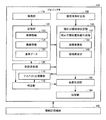
次に、これらの機能を有するプロジェクタ100の機能ブロックについて説明する。図4は、第1の実施例におけるプロジェクタ100の機能ブロック図である。プロジェクタ100は、スクリーン10に投写されたキャリブレーション画像を撮像して撮像画像を示す撮像情報を生成する撮像部110と、種々のデータを記憶する記憶部120と、撮像情報に基づき、スクリーン10の少なくとも一部の形状を決定する形状決定部130とを含んで構成されている。
Next, functional blocks of
また、記憶部120は、画像を生成するための画像情報122、撮像部110からの撮像情報124、基準アスペクト比や判定基準値等を示す基準データ126等を記憶している。
Further, the
また、プロジェクタ100は、補正目標領域を設定する補正目標領域設定部140と、投写パネルの一種である液晶パネルの補正目標領域に画像を生成する画像生成部150と、当該画像を投写する投写部190と、補正目標領域のアスペクト比を演算するアスペクト比演算部170と、種々の判定を行う判定部172と、プロジェクタ100の縦方向の投写角度を判定する縦投写角判定部180とを含んで構成されている。
The
また、補正目標領域設定部140は、形状決定部130からの情報に基づき、補正目標位置情報を生成する補正目標位置情報生成部142と、撮像領域の座標値を液晶パネルの座標値に変換する座標変換部144と、当該座標値に基づき、補正目標領域を設定する領域設定部146とを含んで構成されている。
Further, the correction target
なお、これらの各部の機能をプロジェクタ100に実装するためのハードウェアとしては、例えば、以下のハードウェアが採用されてもよい。例えば、撮像部110としてはCCDセンサー等、記憶部120としてはRAM、HDD等、形状決定部130、補正目標領域設定部140、アスペクト比演算部170、判定部172としてはCPU等、画像生成部150としては画像処理回路、液晶駆動回路等、縦投写角判定部180としては角度センサー等、投写部190としては液晶パネル、ランプ、投写レンズ等が採用されてもよい。
For example, the following hardware may be employed as hardware for implementing the functions of these units in the
なお、プロジェクタ100は、これらの各部の機能を実装するためのプログラムを記憶した情報記憶媒体200から当該プログラムを読み取って各部の機能を実装してもよい。このような情報記憶媒体200としては、例えば、CD−ROM、DVD−ROM、ROM、RAM、HDD等を適用でき、そのプログラムの読み取り方式は接触方式であっても、非接触方式であってもよい。
Note that the
次に、これらの各部を用いた投写手順について説明する。図5は、第1の実施例における投写手順を示すフローチャートである。例えば、プロジェクタ100は、プロジェクタ100が起動した場合、ユーザーから補正指示があった場合等に画像の歪みを補正する。画像の歪みを補正する場合、まず、画像生成部150は、画像情報122に基づき、キャリブレーション画像を生成し、投写部190は、当該キャリブレーション画像をスクリーン10へ向け投写する(ステップS1)。
Next, a projection procedure using these parts will be described. FIG. 5 is a flowchart showing a projection procedure in the first embodiment. For example, the
撮像部110は、スクリーン10に投写されたキャリブレーション画像を撮像して撮像情報124を生成し、記憶部120に記憶する(ステップS2)。本実施例では、プロジェクタ100は、3種類のキャリブレーション画像を投写し、撮像する。
The
図6(A)は、全白のキャリブレーション画像300を示す図であり、図6(B)は、中央白のキャリブレーション画像301を示す図であり、図6(C)は、全黒のキャリブレーション画像302を示す図である。まず、プロジェクタ100は、全白(画像全体が白)のキャリブレーション画像300を投写し、自動露出で撮像する。
6A is a diagram showing an all-
次に、プロジェクタ100は、全体の画像と比例形状の中央領域(例えば、画像全体の9分の1の領域であって、画像の中央にある領域)が白であり、中央領域以外の領域が黒であるキャリブレーション画像301を投写し、キャリブレーション画像300撮像時の自動露出によって決定された露出で撮像する。さらに、プロジェクタ100は、全黒(画像全体が黒)のキャリブレーション画像302を投写し、キャリブレーション画像300撮像時の自動露出によって決定された露出で撮像する。
Next, in the
図7(A)は、全白のキャリブレーション画像300の撮像画像400を示す図であり、図7(B)は、中央白のキャリブレーション画像301の撮像画像401を示す図であり、図7(C)は、全黒のキャリブレーション画像302の撮像画像402を示す図である。
7A is a diagram illustrating a captured
例えば、図7(A)に示すように、キャリブレーション画像300の一部がスクリーン10の外部にはみ出している場合であっても、図7(B)に示すように、キャリブレーション画像301の中央領域はスクリーン10上に投写されている。これにより、プロジェクタ100は、スクリーン10における全白画像の輝度値、形状等を把握することができる。なお、3種類のキャリブレーション画像300〜302の撮像順序は任意である。
For example, as shown in FIG. 7A, even if a part of the
形状決定部130は、撮像部110による上記3種類の撮像が終了したかどうかを判定し(ステップS3)、撮像が終了した場合、撮像情報124に基づき、撮像領域におけるスクリーン10の位置を示す投写対象位置情報を生成する(ステップS4)。具体的には、例えば、形状決定部130は、撮像画像400と撮像画像402との差分画像を生成し、当該差分画像に対してエッジ検出等を行うことにより、撮像領域におけるスクリーン10と背景部分との境界線を決定し、当該境界線の位置に関する投写対象位置情報を生成する。なお、差分画像を用いるのは蛍光灯等の光が撮像画像400等に写ることによるノイズの影響をなくすためである。
The
補正目標位置情報生成部142は、形状決定部130からの投写対象位置情報に基づき、補正目標位置情報を生成する(ステップS5)。図8は、撮像画像403における補正後のスクリーン10の一例を示す図である。例えば、補正目標位置情報生成部142は、撮像画像403におけるスクリーン10を1画素分大きくした領域ABCD(図8の破線で示す領域)を設定し、領域ABCDの位置に関する(例えば、当該領域の4隅の撮像領域における座標値等を示す)補正目標位置情報を生成する。
The correction target position
座標変換部144は、補正目標位置情報生成部142からの補正目標位置情報に基づき、領域ABCDの撮像領域における座標値を液晶パネルにおける座標値に変換する(ステップS6)。なお、この変換としては、具体的には、例えば、射影変換等が該当する。
The coordinate
領域設定部146は、座標変換部144による座標変換後の座標値に基づき、補正目標領域を設定する(ステップS7)。次に、補正目標領域の設定について、より詳細に説明する。図9は、第1の実施例における補正目標領域設定手順を示すフローチャートである。
The
領域設定部146は、形状決定部130によって差分画像におけるスクリーン10の4辺が検出されたかどうかを判定する(ステップS11)。また、領域設定部146は、4辺が検出されなかった場合、スクリーン10の3辺が検出されたかどうかを判定する(ステップS12)。
The
図10は、垂直消失点Vと水平消失点Hを示す模式図である。例えば、図10に示す例では、スクリーン10の上辺、下辺、左辺の3辺が検出されている。領域設定部146は、3辺が検出されている場合、垂直、水平のどちらか一方の消失点に基づき、もう一方の消失点を決定する(ステップS13)。
FIG. 10 is a schematic diagram showing the vertical vanishing point V and the horizontal vanishing point H. FIG. For example, in the example shown in FIG. 10, three sides of the upper side, the lower side, and the left side of the
具体的には、例えば、領域設定部146は、図10に示す例の場合、Z=1である平面に仮想投写面14を設定し、スクリーン10の上辺の延長線と下辺の延長線が交わる水平消失点Hの座標値を演算する。
Specifically, for example, in the example shown in FIG. 10, the
垂直消失点Vは左辺の延長線上にあり、かつ、各消失点と原点Oのなす角HOVは直角である。領域設定部146は、この性質を利用してスクリーン10の左辺の延長線と右辺の延長線が交わる垂直消失点Vの座標値を演算する。
The vertical vanishing point V is on the extension line of the left side, and the angle HOV formed by each vanishing point and the origin O is a right angle. Using this property, the
一方、3辺が検出されていない場合、領域設定部146は、スクリーン10の縦辺(左辺または右辺)と横辺(上辺または下辺)が検出されているかどうかを判定する(ステップS14)。縦辺と横辺が検出されている場合、領域設定部146は、縦投写角、横投写角、ロール角が変数の式に基づき、各消失点を決定する(ステップS15)。
On the other hand, when the three sides are not detected, the
例えば、縦投写角をθ、横投写角をφ、ロール角をψとすると、仮想投写面14における各消失点の座標値(X,Y)は、
For example, if the vertical projection angle is θ, the horizontal projection angle is φ, and the roll angle is ψ, the coordinate values (X, Y) of the vanishing points on the

また、ここで、縦投写角は、例えば、スクリーン10と投写部190による投写光の光軸との垂直方向の相対的な角度のことであり、横投写角は、例えば、スクリーン10と投写部190による投写光の光軸との水平方向の相対的な角度のことである。また、縦投写角は縦投写角判定部180によって判定されるプロジェクタ100の垂直方向の傾きを示す値であってもよい。
Here, the vertical projection angle is, for example, a relative angle in the vertical direction between the
領域設定部146は、縦投写角判定部180によって判定されたプロジェクタ100の垂直方向の傾きを示す値をθに代入することにより、上記の式をφとψの連立方程式として解くことができ、垂直消失点と水平消失点を決定することができる。
The
一方、横辺と縦辺が検出されていない場合、領域設定部146は、スクリーン10の上辺と下辺が検出されているかどうかを判定する(ステップS16)。上辺と下辺が検出されている場合、領域設定部146は、ステップS15と同様に各消失点を決定する(ステップS17)。具体的には、領域設定部146は、上辺と下辺の位置情報から水平消失点を決定することができる。また、垂直消失点は、ステップS15と同様に、縦投写角判定部180によって判定されたプロジェクタ100の垂直方向の傾きを示す値をθに代入することにより、上記の式をφとψの連立方程式として解くことができ、垂直消失点を決定することができる。
On the other hand, when the horizontal side and the vertical side are not detected, the
一方、上辺と下辺が検出されていない場合、領域設定部146は、スクリーン10の上辺または下辺が検出されているかどうかを判定する(ステップS18)。上辺または下辺が検出されている場合、領域設定部146は、特開2006−60447号に記載された従来の手法を用いて各消失点を決定する(ステップS19)。
On the other hand, when the upper side and the lower side are not detected, the
また、以上の条件のいずれにも当てはまらない場合、画像生成部150は、画像情報122に基づき、画像の歪みを補正できないことを示す画像を生成し、投写部190は、当該画像を投写し(ステップS20)、プロジェクタ100は歪み補正処理を終了する。
When none of the above conditions is satisfied, the
また、領域設定部146は、ステップS13、S15、S17、S19のいずれかの処理によって消失点を決定した場合、既知のスクリーン10の座標値と、各消失点の座標値に基づき、補正目標領域の不足辺を補完する(ステップS21)。
Further, when the vanishing point is determined by any one of steps S13, S15, S17, and S19, the
以上の手順により補正目標領域の形状が決定される。補正目標領域の形状が決定された状態で、領域設定部146は、補正目標領域のアスペクト比を補正する(ステップS22)。ここで、アスペクト比補正手順についてより詳細に説明する。図11は、第1の実施例におけるアスペクト比補正手順を示すフローチャートである。
The shape of the correction target area is determined by the above procedure. In a state where the shape of the correction target area is determined, the
アスペクト比演算部170は、領域設定部146によって決定された補正目標領域のアスペクト比を演算する(ステップS30)。なお、アスペクト比は、縦辺の長さを横辺の長さで割った値である。例えば、横辺の長さ:縦辺の長さが4:3であれば、アスペクト比は0.75である。
The aspect
判定部172は、形状決定部130によってスクリーン10の4辺が検出されたかどうかを判定する(ステップS31)。当該4辺が検出されている場合、判定部172は、条件を補正目標領域のアスペクト比と基準アスペクト比の差が10%以内に設定する(ステップS32)。
The
なお、基準アスペクト比は、例えば、プロジェクタ100の製造業者やユーザーによって設定される望ましいアスペクト比のことであり、基準データ126の一部として記憶部120に記憶されている。例えば、基準アスペクト比が0.75である場合、上記条件は補正目標領域のアスペクト比が0.675以上0.825以下となる。
The reference aspect ratio is a desirable aspect ratio set by the manufacturer or user of the
また、判定部172は、上記4辺が検出されていない場合、条件を補正目標領域のアスペクト比と基準アスペクト比の差が3%以内に設定する(ステップS32)。例えば、基準アスペクト比が0.75である場合、この条件は補正目標領域のアスペクト比が0.7275以上0.7725以下となる。
Further, when the four sides are not detected, the
そして、判定部172は、アスペクト比演算部170によって演算された補正目標領域のアスペクト比が、設定した条件を満たすかどうかを判定する(ステップS34)。条件を満たさない場合、判定部172は、基準アスペクト比になるように補正目標領域を設定する(ステップS35)。
Then, the
判定部172は、液晶パネルにおける最終的な補正目標領域の4隅の座標値を示す情報を画像生成部150に出力する。画像生成部150は、当該情報と、画像情報122に基づき、液晶パネルにおける補正目標領域に画像を生成する(ステップS8)。投写部190は、当該画像を投写する(ステップS9)。
The
以上のように、本実施例によれば、プロジェクタ100は、補正目標領域のアスペクト比と基準アスペクト比との相違を示す値が設定条件を満たすかどうかを判定し、当該判定結果に応じたアスペクト比で画像を投写することにより、状況に応じたアスペクト比で画像を投写することができる。
As described above, according to the present embodiment, the
また、本実施例によれば、プロジェクタ100は、撮像情報に基づいてスクリーン10の少なくとも一部の形状を決定することができるため、操作情報を入力することなく、正確に画像の歪みを補正でき、所望のアスペクト比で画像を投写することができる。
Further, according to the present embodiment, the
また、本実施例によれば、プロジェクタ100は、撮像画像にスクリーン10の全部が含まれない場合であってもスクリーン10の未決定部分を補完することができるため、より汎用的に状況に応じたアスペクト比で画像を投写することができる。
In addition, according to the present embodiment, the
また、本実施例によれば、プロジェクタ100は、アスペクト比の相違を範囲で判定することにより、測定誤差等を吸収することができるため、スクリーン10に非表示領域が発生する事態の発生を抑制することができる。
In addition, according to the present embodiment, the
また、本実施例によれば、プロジェクタ100は、形状決定部130によってスクリーン10の全形状が決定されない場合は当該全形状が決定される場合と比べて判定用の範囲を狭く設定することにより、画像の歪み等が大きい場合により厳しく判定することができ、誤った形状で画像を投写する事態の発生を抑制することができる。
Further, according to the present embodiment, when the entire shape of the
また、本実施例によれば、プロジェクタ100は、スクリーン10の形状よりも少なくとも1画素分広い領域を補正目標領域として設定することにより、スクリーン10に非表示領域が発生する事態の発生を抑制することができる。
Further, according to the present embodiment, the
また、本実施例によれば、プロジェクタ100は、投写パネルの座標系におけるスクリーン10の辺によって形成される垂直方向および水平方向の消失点の座標値を決定するととともに、当該座標値に基づき、形状決定部130によるスクリーン10の未決定部分を補完することにより、プロジェクタ100が、投写光の光軸に対して傾いている場合や撮像部110の取り付け誤差が発生している場合であっても正確に画像の歪みを補正することができる。
Further, according to the present embodiment, the
また、本実施例によれば、プロジェクタ100は、プロジェクタ100の回転角を変数とする演算を行うことにより、投写光の光軸に対して傾いている場合であっても正確に画像の歪みを補正することができる。また、本実施例によれば、プロジェクタ100は、当該回転角を0度として演算することにより、プロジェクタ100の回転角を変数とする演算を行うことができない場合であっても、画像の歪みを補正することができる。
Further, according to the present embodiment, the
また、本実施例によれば、プロジェクタ100は、投写パネルにおける座標値に基づいて補正目標領域を設定することにより、撮像部110の取り付け状態に誤差が生じている場合であっても画像の歪みを適切に補正することができる。
Further, according to the present embodiment, the
(消失点の求め方についての説明)
ここで、上述した消失点の求め方についてより詳細に説明する。ピッチ角θとヨー角φを固定しておけば、スクリーン10がロール方向に回転しても補正形状には影響しないため、ピッチ角θ、ヨー角φ、ロール角ψの順序でプロジェクタ100を回転させることとする。
(Explanation on how to find vanishing points)
Here, the method for obtaining the vanishing point will be described in more detail. If the pitch angle θ and the yaw angle φ are fixed, the correction shape is not affected even if the
ピッチ角θ、ヨー角φ、ロール角ψの回転を行う3次元の回転行列は、 A three-dimensional rotation matrix that rotates the pitch angle θ, the yaw angle φ, and the roll angle ψ is:
これは、プロジェクタ100を外から見たときの回転であり、プロジェクタ100自身からはこの行列とは反対方向に回転しているように見える。したがって、プロジェクタ100から見たスクリーン10の回転を表す座標変換行列はこの逆行列になる。回転行列は、直交行列の一種であるため、逆行列を求めるには、
This is a rotation when the
転置行列R’で回転前の水平方向の無限遠点[1:0:0]と垂直方向の無限遠点[0:1:0]を回転させると消失点を求めることができる。すなわち、3次元空間においては、垂直消失点と水平消失点は互いに直交している。なお、奥行方向の無限遠点[0:0:1]を回転させるとスクリーン10の法線を求めることができる。具体的には、
垂直消失点V=[sinψcosφ:-sinψsinφsinθ+cosψcosθ:sinψsinφcosθ+cosψsinθ]・・・式(3)
水平消失点H=[cosψcosφ:-cosψsinφsinθ-sinψcosθ:cosψsinφcosθ-sinψsinθ]・・・式(4)
スクリーン10の法線=[-sinφ:-cosφsinθ:cosφcosθ]
となる。
The vanishing point can be obtained by rotating the horizontal infinity point [1: 0: 0] and the vertical infinity point [0: 1: 0] before rotation in the transposed matrix R ′. That is, in the three-dimensional space, the vertical vanishing point and the horizontal vanishing point are orthogonal to each other. Note that the normal line of the
Vertical vanishing point V = [sinψcosφ: -sinψsinφsinθ + cosψcosθ: sinψsinφcosθ + cosψsinθ] (3)
Horizontal vanishing point H = [cosψcosφ: -cosψsinφsinθ-sinψcosθ: cosψsinφcosθ-sinψsinθ] (4)
Normal of
It becomes.
なお、ここで、[x:y:z]は射影幾何学における点(x,y,z)を表している。垂直消失点Vと水平消失点Hの3次元座標値をZ成分で割ることにより、上述した式(1)および(2)で座標値を表すことができる。 Here, [x: y: z] represents a point (x, y, z) in projective geometry. By dividing the three-dimensional coordinate values of the vertical vanishing point V and the horizontal vanishing point H by the Z component, the coordinate values can be expressed by the above-described equations (1) and (2).
また、垂直消失点Vとスクリーン10の横辺から水平消失点を求める場合は以下の演算を行えばよい。上述したように、垂直消失点Vと水平消失点Hは3次元空間では直交している。したがって、垂直消失点V[a:b:c]とすると、水平消失点HはVを法線とする平面上になければならない。Vを法線とする平面の方程式はax+by+cz=0なので、z=1を代入すれば、水平消失点Hは直線ax+by+c=0上にあることになる。したがって、水平消失点Hは横辺と直線ax+by+c=0の交点として求められる。
Further, when the horizontal vanishing point is obtained from the vertical vanishing point V and the horizontal side of the
また、スクリーン10の縦辺および横辺と縦投写角θから以下の演算を行うことにより、垂直消失点Vを求めることができる。まず、左辺または右辺の式をAx+By+C=0とし、上辺または下辺の式をDx+Ey+F=0とする。
Further, the vertical vanishing point V can be obtained by performing the following calculation from the vertical and horizontal sides of the
上述した垂直消失点Vおよび水平消失点Hの式をそれぞれ縦辺および横辺の式に代入してまとめると、
0=Atanψcosφ+Bcosθ+Csinθ+(-Bsinθ+Ccosθ)tanψsinφ
0=Dcosφ-(Ecosθ+Fsinθ)tanψ+(-Esinθ+Fcosθ)sinφ
となる。縦投写角判定部180からθを得ることができ、この2式に含まれる未知数はφとψだけとなるため、垂直消失点Vを求めることができる。
Substituting the above formulas for the vertical vanishing point V and the horizontal vanishing point H into the vertical and horizontal sides respectively,
0 = Atanψcosφ + Bcosθ + Csinθ + (-Bsinθ + Ccosθ) tanψsinφ
0 = Dcosφ- (Ecosθ + Fsinθ) tanψ + (-Esinθ + Fcosθ) sinφ
It becomes. Since θ can be obtained from the vertical projection
また、水平消失点Hと縦投写角θから以下の演算を行うことにより、垂直消失点Vを求めることができる。まず、式(3)および(4)を縦投写角判定部180からのθを用いてX軸に対して回転すると、
垂直消失点V’=[sinψcosφ:cosψ:sinψsinφ]
水平消失点H’=[cosψcosφ:-sinψ:cosψsinφ]
となる。
Further, the vertical vanishing point V can be obtained by performing the following calculation from the horizontal vanishing point H and the vertical projection angle θ. First, when Expressions (3) and (4) are rotated with respect to the X axis using θ from the vertical projection
Vertical vanishing point V ′ = [sinψcosφ: cosψ: sinψsinφ]
Horizontal vanishing point H ′ = [cosψcosφ: -sinψ: cosψsinφ]
It becomes.
水平消失点Hは既知であるため、θ回転したH’の成分も求められる。そこで、H’の成分からV’を求めるため、V’の成分を定数倍すると、
垂直消失点V’=[cosφ:cosψ/sinψ:sinφ]
=[cosψcosφ:-sinψ-(1/-sinψ):cosψsinφ]
となる。
Since the horizontal vanishing point H is known, the component of H ′ rotated by θ is also obtained. Therefore, in order to obtain V ′ from the component of H ′, multiplying the component of V ′ by a constant,
Vertical vanishing point V ′ = [cosφ: cosψ / sinψ: sinφ]
= [cosψcosφ: -sinψ- (1 / -sinψ): cosψsinφ]
It becomes.
したがって、この式のY成分をV'y=H'y-(1/H'y)と置き換えるとH’からV’を求めることができる。V’が求められた場合、X軸を中心に−θ回転させることにより、垂直消失点Vを求めることができる。 Therefore, V ′ can be obtained from H ′ by replacing the Y component of this equation with V′y = H′y− (1 / H′y). When V ′ is obtained, the vertical vanishing point V can be obtained by rotating by −θ about the X axis.
また、縦投写角判定部180からのθのみから垂直消失点Vを求める場合は、ロール角ψを0度とする。式(1)にψ=0を代入すると、垂直消失点V=(0,1/tanθ)となり、θから垂直消失点Vを求めることができる。
When the vertical vanishing point V is obtained only from θ from the vertical projection
(第2の実施例)
図12は、第2の実施例におけるプロジェクタ101の機能ブロック図である。プロジェクタ101は、撮像部110に代えてユーザーの操作情報128を入力する操作部160を有している。また、記憶部120は、撮像情報124に代えて操作情報128を記憶する。
(Second embodiment)
FIG. 12 is a functional block diagram of the
例えば、ユーザーがリモコン(リモートコントローラ)を用いて投写画像12の4隅をスクリーン10の4隅に移動させる操作を行った場合、操作部160は、当該操作の内容を示す操作情報128を入力し、記憶部120に記憶する。形状決定部130は、操作情報128に基づいてスクリーン10の形状を決定し、補正目標領域設定部140は、当該形状に応じて補正目標領域を設定する。
For example, when the user performs an operation of moving the four corners of the projected
以上のように、撮像情報を用いない場合であっても、プロジェクタ101は、第1の実施例と同様に、正確に画像の歪みを補正することができる。
As described above, even when the imaging information is not used, the
(その他の実施例)
なお、本発明の適用は上述した実施例に限定されず、種々の変形が可能である。例えば、本発明の適用は、画像の歪み補正には限定されず、例えば、指示位置の検出、画像の明るさ補正、画像の色補正等に適用されてもよい。
(Other examples)
In addition, application of this invention is not limited to the Example mentioned above, A various deformation | transformation is possible. For example, the application of the present invention is not limited to image distortion correction, and may be applied to, for example, indication position detection, image brightness correction, and image color correction.
また、ステップS32における条件の値は10%には限定されず、ステップS33における条件の値も3%には限定されず、任意の数値を適用可能である。また、ステップS32およびステップS33における条件が同一の条件であってもよい。また、ステップS32〜S34では、判定部172は、補正目標領域のアスペクト比と基準アスペクト比との差分値を用いて判定しているが、差分値以外にも、例えば、比率等の相違を示す種々の値を採用可能である。
Further, the value of the condition in step S32 is not limited to 10%, and the value of the condition in step S33 is not limited to 3%, and any numerical value can be applied. Moreover, the conditions in step S32 and step S33 may be the same conditions. In steps S32 to S34, the
また、上述した実施例ではスクリーン10よりも1画素分大きい領域を適用したが、スクリーン10と一致する領域であってもよく、スクリーン10よりも2画素分以上大きい領域であってもよい。また、当該領域は、液晶パネルの画素数と撮像領域の画素数の比率から決定されてもよい。
In the above-described embodiment, an area that is one pixel larger than the
また、プロジェクタ100、101がズーム機能を有する場合、プロジェクタ100、101は、ズーム状態に応じた補正を行ってもよい。また、上述した実施例では、撮像画像の差分画像を用いているが、撮像画像400、401をそのまま用いてもよい。また、キャリブレーション画像は、上述したキャリブレーション画像300〜302には限定されない。例えば、プロジェクタ100、101は、キャリブレーション画像300のみを用いてもよいし、キャリブレーション画像301のみを用いてもよいし、キャリブレーション画像301に代えて白と黒の市松模様のキャリブレーション画像を用いてもよい。
When the
また、投写対象物は、スクリーン10には限定されず、例えば、ホワイトボード、黒板、壁に設けられた長方形枠等の矩形の投写対象領域を有する種々の投写対象物を採用可能である。また、プロジェクタ100、101としては、例えば、液晶プロジェクタ、CRT(Cathode Ray Tube)プロジェクタ、DMD(Digital Micromirror Device)を用いたプロジェクタ等を用いてもよい。なお、DMDは米国テキサスインスツルメンツ社の商標である。
The projection object is not limited to the
10 スクリーン、12 投写画像、14 仮想投写面、20、100、101 プロジェクタ、110 撮像部、120 記憶部、122 画像情報、124 撮像情報、126 基準データ、128 操作情報、130 形状決定部、140 補正目標領域設定部、142 補正目標位置情報生成部、144 座標変換部、146 領域設定部、150 画像生成部、160 操作部、170 アスペクト比演算部、172 判定部、180 縦投写角判定部、190 投写部、200 情報記憶媒体、300〜302 キャリブレーション画像、400〜403 撮像画像 10 screen, 12 projected image, 14 virtual projection plane, 20, 100, 101 projector, 110 imaging unit, 120 storage unit, 122 image information, 124 imaging information, 126 reference data, 128 operation information, 130 shape determination unit, 140 correction Target area setting unit, 142 Correction target position information generation unit, 144 Coordinate conversion unit, 146 Area setting unit, 150 Image generation unit, 160 Operation unit, 170 Aspect ratio calculation unit, 172 Determination unit, 180 Vertical projection angle determination unit, 190 Projection unit, 200 information storage medium, 300 to 302 calibration image, 400 to 403 captured image
Claims (5)
前記投写部によって投写された前記キャリブレーション画像の少なくとも一部と、前記投写対象物の少なくとも一部とを含む領域を撮像して撮像画像を示す撮像情報を生成する撮像部と、
前記撮像情報に基づき、前記投写対象物の少なくとも一部の形状を決定するとともに、前記撮像部の内部の撮像領域における前記投写対象物の位置に関する投写対象位置情報を生成する形状決定部と、
当該形状決定部によって決定された形状に沿った領域であって、かつ、前記投写パネルにおける領域である補正目標領域を設定する補正目標領域設定部と、
を含み、
前記補正目標領域設定部は、
前記投写対象位置情報に基づき、前記撮像領域における前記補正目標領域の位置に関する補正目標位置情報を生成する補正目標位置情報生成部と、
当該補正目標位置情報に基づき、前記撮像領域における前記補正目標領域の座標を、前記投写パネルにおける座標に変換する座標変換部と、
当該座標変換部による変換後の座標に基づき、前記投写パネルにおける前記補正目標領域を設定する領域設定部と、
を含み、
前記補正目標領域設定部は、前記形状決定部によって前記投写対象物の全形状が決定されない場合、前記撮像情報に基づき、前記投写パネルの座標系における前記投写対象物の辺によって形成される垂直方向および水平方向の消失点の座標値を決定するととともに、当該座標値に基づき、前記形状決定部による前記投写対象物の未決定部分を補完することにより、前記補正目標領域を設定することを特徴とするプロジェクタ。 A projection unit that projects a calibration image onto a rectangular projection object via a projection panel;
An imaging unit that captures an area including at least a part of the calibration image projected by the projection unit and at least a part of the projection target, and generates imaging information indicating the captured image;
A shape determining unit that determines at least a part of the shape of the projection target based on the imaging information, and generates projection target position information related to the position of the projection target in the imaging region inside the imaging unit;
A correction target region setting unit that sets a correction target region that is a region along the shape determined by the shape determination unit and is a region in the projection panel;
Including
The correction target area setting unit includes:
A correction target position information generating unit that generates correction target position information related to the position of the correction target area in the imaging area based on the projection target position information;
Based on the correction target position information, a coordinate conversion unit that converts the coordinates of the correction target region in the imaging region into coordinates in the projection panel;
An area setting unit for setting the correction target area in the projection panel based on the coordinates after the conversion by the coordinate conversion unit;
Only including,
The correction target area setting unit, when the entire shape of the projection object is not determined by the shape determination unit, based on the imaging information, a vertical direction formed by the side of the projection object in the coordinate system of the projection panel And determining a coordinate value of the vanishing point in the horizontal direction, and setting the correction target region by complementing an undetermined portion of the projection target by the shape determining unit based on the coordinate value. Projector.
前記補正目標領域のアスペクト比を演算するアスペクト比演算部と、
前記補正目標領域のアスペクト比と基準アスペクト比との相違を示す値が設定条件を満
たすかどうかを判定する判定部と、
前記補正目標領域の形状の画像または基準アスペクト比の画像を生成する画像生成部と、
を含み、
前記画像生成部は、前記設定条件を満たす場合は前記補正目標領域の形状で画像を生成し、前記設定条件を満たさない場合は前記基準アスペクト比の画像を生成することを特徴とするプロジェクタ。 The projector according to claim 1 , wherein
An aspect ratio calculation unit for calculating an aspect ratio of the correction target area;
A determination unit that determines whether a value indicating a difference between an aspect ratio of the correction target area and a reference aspect ratio satisfies a setting condition;
An image generation unit for generating an image of the shape of the correction target region or an image of a reference aspect ratio;
Including
The image generation unit generates an image with the shape of the correction target area when the setting condition is satisfied, and generates an image with the reference aspect ratio when the setting condition is not satisfied.
前記コンピュータを、
キャリブレーション画像を、投写パネルを介して矩形の投写対象物へ向け前記投写部に投写させる投写制御部と、
前記投写部によって投写された前記キャリブレーション画像の少なくとも一部と、前記投写対象物の少なくとも一部とを含む領域を前記撮像部に撮像させて撮像画像を示す撮像情報を生成させる撮像制御部と、
前記撮像情報に基づき、前記投写対象物の少なくとも一部の形状を決定するとともに、前記撮像部の内部の撮像領域における前記投写対象物の位置に関する投写対象位置情報を生成する形状決定部と、
当該形状決定部によって決定された形状に沿った領域であって、かつ、前記投写パネルにおける領域である補正目標領域を設定する補正目標領域設定部として機能させ、
前記補正目標領域設定部は、
前記投写対象位置情報に基づき、前記撮像領域における前記補正目標領域の位置に関する補正目標位置情報を生成する補正目標位置情報生成部と、
当該補正目標位置情報に基づき、前記撮像領域における前記補正目標領域の座標を、前記投写パネルにおける座標に変換する座標変換部と、
当該座標変換部による変換後の座標に基づき、前記投写パネルにおける前記補正目標領域を設定する領域設定部と、
を含み、
前記補正目標領域設定部は、前記形状決定部によって前記投写対象物の全形状が決定されない場合、前記撮像情報に基づき、前記投写パネルの座標系における前記投写対象物の辺によって形成される垂直方向および水平方向の消失点の座標値を決定するととともに、当該座標値に基づき、前記形状決定部による前記投写対象物の未決定部分を補完することにより、前記補正目標領域を設定することを特徴とするプログラム。 A program readable by a computer of a projector including a projection unit and an imaging unit,
The computer,
A projection control unit that causes the projection unit to project a calibration image onto a rectangular projection object via a projection panel;
An imaging control unit that causes the imaging unit to capture an area including at least a part of the calibration image projected by the projection unit and at least a part of the projection target, and generates imaging information indicating the captured image; ,
A shape determining unit that determines at least a part of the shape of the projection target based on the imaging information, and generates projection target position information related to the position of the projection target in the imaging region inside the imaging unit;
A region along the shape determined by the shape determination unit, and function as a correction target region setting unit that sets a correction target region that is a region in the projection panel;
The correction target area setting unit includes:
A correction target position information generating unit that generates correction target position information related to the position of the correction target area in the imaging area based on the projection target position information;
Based on the correction target position information, a coordinate conversion unit that converts the coordinates of the correction target region in the imaging region into coordinates in the projection panel;
An area setting unit for setting the correction target area in the projection panel based on the coordinates after the conversion by the coordinate conversion unit;
Only including,
The correction target area setting unit, when the entire shape of the projection object is not determined by the shape determination unit, based on the imaging information, a vertical direction formed by the side of the projection object in the coordinate system of the projection panel And determining a coordinate value of the vanishing point in the horizontal direction, and setting the correction target region by complementing an undetermined portion of the projection target by the shape determining unit based on the coordinate value. Program to do.
請求項3に記載のプログラムを記憶した情報記憶媒体。 An information storage medium storing a program readable by a computer of a projector including a projection unit and an imaging unit,
An information storage medium storing the program according to claim 3 .
前記コンピュータは、
キャリブレーション画像を、投写パネルを介して矩形の投写対象物へ向け前記投写部に投写させ、
前記投写部によって投写された前記キャリブレーション画像の少なくとも一部と、前記投写対象物の少なくとも一部とを含む領域を前記撮像部に撮像させて撮像画像を示す撮像情報を生成させ、
前記撮像情報に基づき、前記投写対象物の少なくとも一部の形状を決定するとともに、前記撮像部の内部の撮像領域における前記投写対象物の位置に関する投写対象位置情報を生成し、
前記投写対象位置情報に基づき、前記撮像領域における前記形状に沿った領域である補正目標領域の位置に関する補正目標位置情報を生成し、
当該補正目標位置情報に基づき、前記撮像領域における前記補正目標領域の座標を、前記投写パネルにおける座標に変換し、
当該座標変換部による変換後の座標に基づき、前記投写パネルにおける前記補正目標領域を設定し、
前記投写対象物の全形状が決定されない場合、前記撮像情報に基づき、前記投写パネルの座標系における前記投写対象物の辺によって形成される垂直方向および水平方向の消失点の座標値を決定するととともに、当該座標値に基づき、前記投写対象物の未決定部分を補完することにより、前記補正目標領域を設定する、
画像生成方法。 A computer-generated image generation method of a projector including a projection unit and an imaging unit,
The computer
A calibration image is projected on the projection unit toward a rectangular projection object via a projection panel,
Causing the imaging unit to capture an area including at least a part of the calibration image projected by the projection unit and at least a part of the projection target, and generating imaging information indicating the captured image;
Based on the imaging information, determine the shape of at least a part of the projection object, and generate projection target position information related to the position of the projection object in an imaging region inside the imaging unit,
Based on the projection target position information, generate correction target position information related to the position of the correction target area that is an area along the shape in the imaging area,
Based on the correction target position information, the coordinates of the correction target area in the imaging area are converted into coordinates on the projection panel,
Based on the transformed coordinates by the coordinate conversion unit sets the correction target region in the projection panel,
If the entire shape of the projection object is not determined, the coordinate values of the vanishing points in the vertical and horizontal directions formed by the sides of the projection object in the coordinate system of the projection panel are determined based on the imaging information. Based on the coordinate value, the correction target area is set by complementing the undetermined portion of the projection object.
Image generation method.
Priority Applications (1)
| Application Number | Priority Date | Filing Date | Title |
|---|---|---|---|
| JP2007044243A JP5187480B2 (en) | 2007-02-23 | 2007-02-23 | Projector, program, information storage medium, and image generation method |
Applications Claiming Priority (1)
| Application Number | Priority Date | Filing Date | Title |
|---|---|---|---|
| JP2007044243A JP5187480B2 (en) | 2007-02-23 | 2007-02-23 | Projector, program, information storage medium, and image generation method |
Publications (3)
| Publication Number | Publication Date |
|---|---|
| JP2008211356A JP2008211356A (en) | 2008-09-11 |
| JP2008211356A5 JP2008211356A5 (en) | 2010-04-02 |
| JP5187480B2 true JP5187480B2 (en) | 2013-04-24 |
Family
ID=39787316
Family Applications (1)
| Application Number | Title | Priority Date | Filing Date |
|---|---|---|---|
| JP2007044243A Active JP5187480B2 (en) | 2007-02-23 | 2007-02-23 | Projector, program, information storage medium, and image generation method |
Country Status (1)
| Country | Link |
|---|---|
| JP (1) | JP5187480B2 (en) |
Families Citing this family (5)
| Publication number | Priority date | Publication date | Assignee | Title |
|---|---|---|---|---|
| JP5445745B2 (en) * | 2009-06-11 | 2014-03-19 | セイコーエプソン株式会社 | Projector, program, information storage medium, and trapezoidal distortion correction method |
| JP5257618B2 (en) * | 2009-08-07 | 2013-08-07 | セイコーエプソン株式会社 | Projector, program, information storage medium, and exposure adjustment method |
| WO2011141972A1 (en) * | 2010-05-14 | 2011-11-17 | Necディスプレイソリューションズ株式会社 | Luminosity correction device, luminosity correction system, and luminosity correction method |
| JP5541031B2 (en) * | 2010-09-16 | 2014-07-09 | セイコーエプソン株式会社 | Projector and projector control method |
| CN113365041B (en) * | 2021-02-24 | 2022-03-22 | 深圳市火乐科技发展有限公司 | Projection correction method, projection correction device, storage medium and electronic equipment |
Family Cites Families (6)
| Publication number | Priority date | Publication date | Assignee | Title |
|---|---|---|---|---|
| US6520647B2 (en) * | 2000-08-17 | 2003-02-18 | Mitsubishi Electric Research Laboratories Inc. | Automatic keystone correction for projectors with arbitrary orientation |
| US6527395B1 (en) * | 2001-12-10 | 2003-03-04 | Mitsubishi Electric Research Laboratories, Inc. | Method for calibrating a projector with a camera |
| JP2004260785A (en) * | 2002-07-23 | 2004-09-16 | Nec Viewtechnology Ltd | Projector with distortion correction function |
| JP4006601B2 (en) * | 2004-03-29 | 2007-11-14 | セイコーエプソン株式会社 | Image processing system, projector, program, information storage medium, and image processing method |
| JP2005326247A (en) * | 2004-05-14 | 2005-11-24 | Nippon Telegr & Teleph Corp <Ntt> | Calibrator, calibration method, and calibration program |
| JP3925521B2 (en) * | 2004-08-19 | 2007-06-06 | セイコーエプソン株式会社 | Keystone correction using part of the screen edge |
-
2007
- 2007-02-23 JP JP2007044243A patent/JP5187480B2/en active Active
Also Published As
| Publication number | Publication date |
|---|---|
| JP2008211356A (en) | 2008-09-11 |
Similar Documents
| Publication | Publication Date | Title |
|---|---|---|
| JP4340923B2 (en) | Projector, program, and information storage medium | |
| JP5257616B2 (en) | Projector, program, information storage medium, and trapezoidal distortion correction method | |
| JP3925521B2 (en) | Keystone correction using part of the screen edge | |
| JP5067536B2 (en) | Projector, program, information storage medium, and image generation method | |
| JP4055010B2 (en) | Image processing system, projector, program, information storage medium, and image processing method | |
| JP3844076B2 (en) | Image processing system, projector, program, information storage medium, and image processing method | |
| JP5266954B2 (en) | Projection display apparatus and display method | |
| JP5266953B2 (en) | Projection display apparatus and display method | |
| TWI249351B (en) | Image processing system, projector, and image processing method | |
| JP4232042B2 (en) | Projection control system, projector, program, information storage medium, and projection control method | |
| US8449121B2 (en) | Image processing system, projector, method and computer program product | |
| JP2010122273A (en) | Method of measuring zoom ratio of projection optical system, method of correcting projection image using the method, and projector executing the correction method | |
| CN114727081B (en) | Projector projection correction method and device and projector | |
| JP5187480B2 (en) | Projector, program, information storage medium, and image generation method | |
| JP5561503B2 (en) | Projector, program, information storage medium, and trapezoidal distortion correction method | |
| JP5093517B2 (en) | Projector, program, information storage medium, and image generation method | |
| US20220292652A1 (en) | Image generation method and information processing device | |
| JP3882928B2 (en) | Image processing system, projector, and image processing method | |
| JP3882927B2 (en) | Image processing system, projector, and image processing method | |
| JP2010288062A (en) | Projector, program, information storage medium, and image projection method | |
| JP5110260B2 (en) | Projector, program, information storage medium, and image distortion correction method | |
| JP5445745B2 (en) | Projector, program, information storage medium, and trapezoidal distortion correction method | |
| JP5354163B2 (en) | Projector, program and information storage medium | |
| JP2023546037A (en) | image recording device | |
| WO2012172655A1 (en) | Projector and control method thereof |
Legal Events
| Date | Code | Title | Description |
|---|---|---|---|
| RD04 | Notification of resignation of power of attorney |
Free format text: JAPANESE INTERMEDIATE CODE: A7424 Effective date: 20080702 |
|
| A521 | Request for written amendment filed |
Free format text: JAPANESE INTERMEDIATE CODE: A523 Effective date: 20100215 |
|
| A621 | Written request for application examination |
Free format text: JAPANESE INTERMEDIATE CODE: A621 Effective date: 20100215 |
|
| A977 | Report on retrieval |
Free format text: JAPANESE INTERMEDIATE CODE: A971007 Effective date: 20120314 |
|
| A131 | Notification of reasons for refusal |
Free format text: JAPANESE INTERMEDIATE CODE: A131 Effective date: 20120418 |
|
| A521 | Request for written amendment filed |
Free format text: JAPANESE INTERMEDIATE CODE: A523 Effective date: 20120608 |
|
| TRDD | Decision of grant or rejection written | ||
| A01 | Written decision to grant a patent or to grant a registration (utility model) |
Free format text: JAPANESE INTERMEDIATE CODE: A01 Effective date: 20121226 |
|
| A61 | First payment of annual fees (during grant procedure) |
Free format text: JAPANESE INTERMEDIATE CODE: A61 Effective date: 20130108 |
|
| FPAY | Renewal fee payment (event date is renewal date of database) |
Free format text: PAYMENT UNTIL: 20160201 Year of fee payment: 3 |
|
| R150 | Certificate of patent or registration of utility model |
Ref document number: 5187480 Country of ref document: JP Free format text: JAPANESE INTERMEDIATE CODE: R150 Free format text: JAPANESE INTERMEDIATE CODE: R150 |
|
| S531 | Written request for registration of change of domicile |
Free format text: JAPANESE INTERMEDIATE CODE: R313531 |
|
| R350 | Written notification of registration of transfer |
Free format text: JAPANESE INTERMEDIATE CODE: R350 |