JP5180207B2 - Acoustic transducer array signal processing - Google Patents
Acoustic transducer array signal processing Download PDFInfo
- Publication number
- JP5180207B2 JP5180207B2 JP2009522977A JP2009522977A JP5180207B2 JP 5180207 B2 JP5180207 B2 JP 5180207B2 JP 2009522977 A JP2009522977 A JP 2009522977A JP 2009522977 A JP2009522977 A JP 2009522977A JP 5180207 B2 JP5180207 B2 JP 5180207B2
- Authority
- JP
- Japan
- Prior art keywords
- array
- frequency
- transducer
- signal
- frequency range
- Prior art date
- Legal status (The legal status is an assumption and is not a legal conclusion. Google has not performed a legal analysis and makes no representation as to the accuracy of the status listed.)
- Expired - Fee Related
Links
Images


Classifications
-
- G—PHYSICS
- G10—MUSICAL INSTRUMENTS; ACOUSTICS
- G10K—SOUND-PRODUCING DEVICES; METHODS OR DEVICES FOR PROTECTING AGAINST, OR FOR DAMPING, NOISE OR OTHER ACOUSTIC WAVES IN GENERAL; ACOUSTICS NOT OTHERWISE PROVIDED FOR
- G10K11/00—Methods or devices for transmitting, conducting or directing sound in general; Methods or devices for protecting against, or for damping, noise or other acoustic waves in general
- G10K11/18—Methods or devices for transmitting, conducting or directing sound
- G10K11/26—Sound-focusing or directing, e.g. scanning
- G10K11/34—Sound-focusing or directing, e.g. scanning using electrical steering of transducer arrays, e.g. beam steering
- G10K11/341—Circuits therefor
-
- H—ELECTRICITY
- H04—ELECTRIC COMMUNICATION TECHNIQUE
- H04R—LOUDSPEAKERS, MICROPHONES, GRAMOPHONE PICK-UPS OR LIKE ACOUSTIC ELECTROMECHANICAL TRANSDUCERS; DEAF-AID SETS; PUBLIC ADDRESS SYSTEMS
- H04R3/00—Circuits for transducers, loudspeakers or microphones
- H04R3/12—Circuits for transducers, loudspeakers or microphones for distributing signals to two or more loudspeakers
-
- H—ELECTRICITY
- H04—ELECTRIC COMMUNICATION TECHNIQUE
- H04R—LOUDSPEAKERS, MICROPHONES, GRAMOPHONE PICK-UPS OR LIKE ACOUSTIC ELECTROMECHANICAL TRANSDUCERS; DEAF-AID SETS; PUBLIC ADDRESS SYSTEMS
- H04R1/00—Details of transducers, loudspeakers or microphones
- H04R1/20—Arrangements for obtaining desired frequency or directional characteristics
- H04R1/32—Arrangements for obtaining desired frequency or directional characteristics for obtaining desired directional characteristic only
- H04R1/40—Arrangements for obtaining desired frequency or directional characteristics for obtaining desired directional characteristic only by combining a number of identical transducers
- H04R1/403—Arrangements for obtaining desired frequency or directional characteristics for obtaining desired directional characteristic only by combining a number of identical transducers loud-speakers
-
- H—ELECTRICITY
- H04—ELECTRIC COMMUNICATION TECHNIQUE
- H04R—LOUDSPEAKERS, MICROPHONES, GRAMOPHONE PICK-UPS OR LIKE ACOUSTIC ELECTROMECHANICAL TRANSDUCERS; DEAF-AID SETS; PUBLIC ADDRESS SYSTEMS
- H04R2203/00—Details of circuits for transducers, loudspeakers or microphones covered by H04R3/00 but not provided for in any of its subgroups
- H04R2203/12—Beamforming aspects for stereophonic sound reproduction with loudspeaker arrays
Landscapes
- Physics & Mathematics (AREA)
- Engineering & Computer Science (AREA)
- Acoustics & Sound (AREA)
- Otolaryngology (AREA)
- Health & Medical Sciences (AREA)
- General Health & Medical Sciences (AREA)
- Multimedia (AREA)
- Signal Processing (AREA)
- Circuit For Audible Band Transducer (AREA)
- Investigating Or Analyzing Materials By The Use Of Ultrasonic Waves (AREA)
- Obtaining Desirable Characteristics In Audible-Bandwidth Transducers (AREA)
- Measurement Of Velocity Or Position Using Acoustic Or Ultrasonic Waves (AREA)
- Machines For Laying And Maintaining Railways (AREA)
- Arrangements For Transmission Of Measured Signals (AREA)
Abstract
Description
本明細書は、音響トランスデューサアレー信号処理に関する。 This specification relates to acoustic transducer array signal processing.
スピーカーシステムの(時折、ドライバと呼ばれる)音響トランスデューサは、トランスデューサからの放射の出力を増加するために、又は、振幅及び位相を、指向性をもって制御するために、(例えば、音響双極子、又は音響単極子の組のような)アレー内にグループ化されうる。アレーは、例えば、音響双極子、又は音響単極子の組の形式を取っても良い。 An acoustic transducer (sometimes called a driver) of a speaker system is used to increase the output of radiation from the transducer or to control the amplitude and phase with directionality (eg, an acoustic dipole, or acoustic Can be grouped in arrays (such as monopole sets). The array may take the form of, for example, an acoustic dipole or a set of acoustic monopoles.
図7内に示されているように、音響双極子702(例えば、その振動板の前面及び後面から、音声を均等に放射する背面開放型スピーカー)は、θ=0で双極子702の中央平面708に沿って、前面及び後方からの波を相殺して、グラフ700上のθ=±90での軸707に沿って中心を有する2つの極大部分704a及び706a内で効果的にエネルギーを放射する。ヌル(null)といわれる相殺領域は、音声が発生すると知覚される方向を変化させるような、心理音響的効果を生成するのに使用しても良い。図7B及び7C内で示されているように、極大部分は、非対称(図7B内の704b,706b;図7C内の704c,706c)であるとともに、1つの平面上のみ(例えば、図7B内のヌル軸710)又は、複数の平面上(例えば、図7C内のヌル軸712,714に沿って)にヌルがあっても良い。図7Bは、また、理想的な放射パターン716と、実在のトランスデューサ(図示せず)によって生成された実際の放射パターンとの間にずれがありうることを説明している。
As shown in FIG. 7, an acoustic dipole 702 (eg, a back-open speaker that radiates sound evenly from the front and rear surfaces of its diaphragm) has a central plane of the
概して、一構成では、第1アレーの複数のトランスデューサが、第1周波数範囲内で相殺的干渉を生成し、第1アレーのトランスデューサは、第2周波数範囲内で相殺的干渉を生成せず、第1アレーの第1トランスデューサ及び第2アレーの第1トランスデューサは、第2周波数範囲内で相殺的干渉を生成するように、第1及び第2アレーのトランスデューサに、出力信号及びクロスフィード信号を提供するように、フィルタが入力信号上で動作する。 In general, in one configuration, the plurality of transducers of the first array produce destructive interference within the first frequency range, the transducers of the first array do not produce destructive interference within the second frequency range, and the first The first transducer in the array and the first transducer in the second array provide output signals and cross-feed signals to the transducers in the first and second arrays so as to generate destructive interference within the second frequency range. As such, the filter operates on the input signal.
実施は、次の特徴の1つ又は複数を具備しても良い。 Implementations may include one or more of the following features.
第1周波数範囲は、対応する波長が第1アレー内のトランスデューサの間の間隔の2倍より大きい周波数範囲を具備する。周波数範囲は、対応する波長が、第1及び第2アレーの間の間隔の2倍より小さい1つである。第2周波数範囲は、対応する波長が第1及び第2アレーの間の間隔の2倍より大きい周波数範囲を具備する。第1周波数範囲は、概ね1kHzから概ね3kHzの間の周波数を具備する。第2周波数範囲は、概ね1kHzの下の周波数を具備する。 The first frequency range comprises a frequency range in which the corresponding wavelength is greater than twice the spacing between the transducers in the first array. The frequency range is one in which the corresponding wavelength is less than twice the spacing between the first and second arrays. The second frequency range comprises a frequency range in which the corresponding wavelength is greater than twice the spacing between the first and second arrays. The first frequency range comprises a frequency between approximately 1 kHz and approximately 3 kHz. The second frequency range comprises frequencies below approximately 1 kHz.
第1周波数範囲は、高域周波数及び低域周波数の間の周波数を具備するとともに、フィルタは、直列接続された、高域周波数にコーナー周波数を具備する反転ローパスフィルタと、低域周波数にコーナー周波数を具備するハイパスフィルタと、ハイパスフィルタと同位相にされるとともに、第1アレーの第2トランスデューサに出力信号を提供するオールパスフィルタと、を具備し、ローパスフィルタとハイパスフィルタとは、第1アレーの第1トランスデューサに出力信号を提供している。フィルタは、第1アレーの第1トランスデューサへの出力信号を、第1アレーの第2トランスデューサへの出力信号に相対的に遅延するように構成される。フィルタは、入力信号が、第1周波数範囲内にあるときに、第2アレーのトランスデューサへのクロスフィード信号を減衰する。第1周波数範囲は、高域周波数及び低域周波数の間の周波数を具備するとともに、フィルタは、低域周波数でコーナー周波数を具備するとともに、クロスフィード信号を第2アレーに提供するローパスフィルタと、ローパスフィルタと同位相にされるとともに、第1アレーに出力信号を提供するオールパスフィルタ周波数を具備する。 The first frequency range includes a frequency between a high frequency and a low frequency, and the filter includes a series-connected inverting low-pass filter having a corner frequency at the high frequency and a corner frequency at the low frequency. And an all-pass filter that is in phase with the high-pass filter and provides an output signal to the second transducer of the first array, wherein the low-pass filter and the high-pass filter are: An output signal is provided to the first transducer. The filter is configured to delay the output signal to the first transducer of the first array relative to the output signal to the second transducer of the first array. The filter attenuates the cross feed signal to the transducers of the second array when the input signal is within the first frequency range. The first frequency range comprises a frequency between a high frequency and a low frequency, and the filter comprises a low frequency and a corner frequency and provides a cross feed signal to the second array; An all-pass filter frequency is provided that is in phase with the low-pass filter and provides an output signal to the first array.
第2周波数範囲は、第1高域周波数より下の周波数を具備するとともに、フィルタは、高域周波数でコーナー周波数を具備するとともに、第2アレーにクロスフィード信号を提供する反転ローパスフィルタと、反転ローパスフィルタと同位相にされるとともに、出力信号を第1アレーに提供するオールパスフィルタフィルタと、を具備する。フィルタは、入力信号が第2周波数範囲内にあるときに、第1アレーの第2トランスデューサへの出力信号を減衰する。第2周波数範囲は、第1高域周波数より下の周波数を具備するとともに、フィルタは、第1高域周波数でコーナー周波数を具備するとともに、第1アレーの第2トランスデューサに出力信号を提供する第1ハイパスフィルタと、ハイパスフィルタと同位相にされるとともに、第1アレーの第1トランスデューサに出力信号を提供する第1オールパスフィルタと、第1オールパスフィルタと同位相にされるとともに、第2アレーの第1トランスデューサにクロスフィード信号を提供する第2オールパスフィルタを具備する。フィルタは、第1高域周波数でコーナー周波数を具備するとともに、第2アレーの第2トランスデューサにクロスフィード信号を提供するとともに、第2オールパスフィルタと位相が一致している第2ハイパスフィルタをさらに具備する。フィルタは、第1高域周波数より低い第2高域周波数より下の周波数を具備する第3周波数範囲内で、第1及び第2アレーの第2トランスデューサに出力信号及びクロスフィード信号を提供する。フィルタは、第2高域周波数でコーナー周波数を具備するとともに、第1及び第2アレーの各々の第2トランスデューサに、それぞれ出力信号及びクロスフィード信号を提供する第1及び第2ローパスフィルタと、第1及び第2ローパスフィルタに、それぞれ、及び互いに同位相にされるとともに、第1及び第2アレーの各々の第1トランスデューサに、それぞれ出力信号及びクロスフィード信号を提供する第1及び第2オールパスフィルタと、を具備する。 The second frequency range comprises a frequency below the first high frequency, the filter comprises a corner frequency at the high frequency and an inverting low pass filter that provides a cross feed signal to the second array; An all-pass filter that is in phase with the low-pass filter and provides an output signal to the first array. The filter attenuates the output signal to the second transducer of the first array when the input signal is within the second frequency range. The second frequency range comprises a frequency below the first high frequency, and the filter comprises a corner frequency at the first high frequency and provides an output signal to the second transducer of the first array. A first all-pass filter that is in phase with the high-pass filter and that provides an output signal to the first transducer of the first array, and is in phase with the first all-pass filter, and A second all-pass filter is provided that provides a cross-feed signal to the first transducer. The filter has a corner frequency at the first high frequency, provides a cross feed signal to the second transducer of the second array, and further includes a second high pass filter that is in phase with the second all pass filter. To do. The filter provides an output signal and a cross-feed signal to the second transducer of the first and second arrays within a third frequency range having a frequency below the second high frequency below the first high frequency. A filter having a corner frequency at a second high frequency and a first and a second low pass filter for providing an output signal and a cross feed signal to a second transducer of each of the first and second arrays; First and second all-pass filters that are respectively in phase with the first and second low-pass filters and provide an output signal and a cross-feed signal to the first transducers of the first and second arrays, respectively. And.
フィルタは、また、相殺的干渉が第3周波数範囲内で生成されないように、第1及び第2アレーのトランスデューサに、出力信号及びクロスフィード信号を提供する。第3周波数範囲は、対応する波長が、第1アレー内のトランスデューサの間の間隔の2倍より小さい周波数範囲を具備する。第3周波数範囲は、概ね3kHzより高い周波数を具備する。第3周波数範囲は、低域周波数より高い周波数を具備するとともに、フィルタは、入力信号が低域周波数より上であるときに、第1アレーの第1トランスデューサを動作させるとともに、第1アレーの第2トランスデューサへの出力信号を減衰するように構成されている。フィルタは、低域周波数でコーナー周波数を具備するとともに、第1アレーの第2トランスデューサに出力信号を提供するローパスフィルタを具備する。フィルタは、また、入力信号が、第3周波数範囲内にあるときに、第2アレーのトランスデューサへのクロスフィード信号を減衰するように構成されている。フィルタは、低域周波数にコーナー周波数を具備するとともに、第1アレーの第2トランスデューサに出力信号を提供する第1ローパスフィルタと、低域周波数に、又はそれより下にコーナー周波数を具備するとともに、第2アレーにクロスフィード信号を提供する第2ローパスフィルタと、第2ローパスフィルタと同位相にされるとともに、第1アレーに出力信号を提供するオールパスフィルタと、を具備する。 The filter also provides an output signal and a cross-feed signal to the transducers of the first and second arrays so that destructive interference is not generated within the third frequency range. The third frequency range comprises a frequency range in which the corresponding wavelength is less than twice the spacing between the transducers in the first array. The third frequency range comprises a frequency that is generally higher than 3 kHz. The third frequency range comprises a frequency higher than the low frequency, and the filter operates the first transducer of the first array and the first frequency of the first array when the input signal is above the low frequency. It is configured to attenuate the output signal to the two transducers. The filter comprises a low frequency filter that provides a corner frequency at a low frequency and provides an output signal to the second transducer of the first array. The filter is also configured to attenuate the cross feed signal to the transducers of the second array when the input signal is within the third frequency range. The filter has a corner frequency at the low frequency, a first low pass filter that provides an output signal to the second transducer of the first array, and a corner frequency at or below the low frequency, A second low-pass filter that provides a cross-feed signal to the second array; and an all-pass filter that is in phase with the second low-pass filter and provides an output signal to the first array.
フィルタは、第1アレーの第1合計入力に出力信号を提供する第1オールパスフィルタと、第1アレーの第1トランスデューサへの入力に出力信号を提供する第2オールパスフィルタと、第1アレーの第2トランスデューサへの第1合計入力に出力信号を提供するとともに直列接続された第1ローパスフィルタ及び第1ハイパスフィルタと、第1アレーの第2トランスデューサへの第2合計入力に出力信号を提供する第2ローパスフィルタと、第2アレーの第1合計入力にクロスフィード信号を提供する第3ローパスフィルタと、第2アレーの第1トランスデューサへの入力にクロスフィード信号を提供する第3オールパスフィルタと、第2アレーの第2トランスデューサへの第1合計入力にクロスフィード信号を提供するとともに直列接続された第4ローパスフィルタ及び第2ハイパスフィルタと、第2アレーの第2トランスデューサへの第2合計入力にクロスフィード信号を提供する第5ローパスフィルタと、を具備する。第2及び第5ローパスフィルタは、低域周波数にコーナー周波数を具備し、第3ローパスフィルタ及び第1及び第2ハイパスフィルタは、中間域周波数にコーナー周波数を具備し、かつ、第1及び第4ローパスフィルタは、高域周波数にコーナー周波数を具備する。フィルタは、第1アレーの第2合計入力にクロスフィード信号を提供する第6ローパスフィルタと、第2アレーの第2合計入力に出力信号を提供する第4オールパスフィルタと、をさらに具備し、第1信号入力は、第1オールパスフィルタ及び第3ローパスフィルタに接続されるとともに、第2信号入力は、第4オールパスフィルタ及び第6ローパスフィルタに接続される。 The filter includes a first all-pass filter that provides an output signal to a first sum input of the first array, a second all-pass filter that provides an output signal to an input to the first transducer of the first array, and a first all-pass filter of the first array. A first sum input to the two transducers and an output signal to a second sum input to the second transducer of the first array and a first low pass filter and a first high pass filter connected in series; A second low-pass filter, a third low-pass filter that provides a cross-feed signal to the first sum input of the second array, a third all-pass filter that provides a cross-feed signal to the input to the first transducer of the second array, and Provides a cross-feed signal to the first sum input to the second transducer of the two arrays and series connection Comprising a fourth low-pass filter and a second high-pass filter, a fifth low-pass filter to provide a cross-feed signals to the second total input to the second transducer of the second array, the. The second and fifth low-pass filters have a corner frequency at a low frequency, the third low-pass filter and the first and second high-pass filters have a corner frequency at an intermediate frequency, and the first and fourth The low-pass filter has a corner frequency at a high frequency. The filter further comprises a sixth low-pass filter that provides a cross-feed signal to the second sum input of the first array, and a fourth all-pass filter that provides an output signal to the second sum input of the second array; One signal input is connected to the first all-pass filter and the third low-pass filter, and the second signal input is connected to the fourth all-pass filter and the sixth low-pass filter.
フィルタは、また、第1アレーのトランスデューサが、追加周波数範囲内の相殺的干渉を生成しないように、第1及び第2アレーのトランスデューサに出力信号及びクロスフィード信号を提供するとともに、第1アレーの複数のトランスデューサ及び第2アレーの複数のトランスデューサは、追加周波数範囲内で相殺的干渉を生成する。追加周波数範囲は、概ね550Hzより下の周波数を具備する。 The filter also provides an output signal and a cross-feed signal to the first and second array transducers so that the first array transducers do not generate destructive interference in the additional frequency range, and The plurality of transducers and the plurality of transducers of the second array generate destructive interference within the additional frequency range. The additional frequency range comprises frequencies below approximately 550 Hz.
フィルタは、また、第2アレーの複数のトランスデューサが第1周波数範囲内で相殺的干渉を生成するために、第2及び第1アレーのトランスデューサに出力信号及びクロスフィード信号を提供するように第2入力信号上で動作し、第2アレーのトランスデューサは、第2周波数範囲内で相殺的干渉を生成せず、かつ第1アレーの第1トランスデューサ及び第2アレーの第1トランスデューサは、第2周波数範囲内で、第1入力信号及び第2入力信号の両方をベースとして、相殺的干渉を生成する。第1入力信号は左信号であるとともに第2入力信号は、右信号である。 The filter is also configured to provide second and second feed signals to the second and first array transducers in order for the plurality of transducers in the second array to generate destructive interference within the first frequency range. Operating on the input signal, the transducer of the second array does not produce destructive interference within the second frequency range, and the first transducer of the first array and the first transducer of the second array are in the second frequency range. A destructive interference is generated based on both the first input signal and the second input signal. The first input signal is a left signal and the second input signal is a right signal.
概して、一構成では、第1アレーのトランスデューサが、第1及び第2周波数範囲のそれぞれで実質的に異なる角度の相殺的干渉を生成するように第1及び第2アレーのトランスデューサを駆動する出力信号及びクロスフィード信号を提供するように、フィルタは入力信号上で動作し、かつ第1アレーのトランスデューサ及び第2アレーのトランスデューサは、第2周波数範囲内で相殺的干渉を生成し、第1アレーを駆動する第1信号及び第2アレーを駆動する第2信号は同一ではない。 In general, in one configuration, an output signal that drives the transducers of the first and second arrays so that the transducers of the first array generate destructive interference at substantially different angles in each of the first and second frequency ranges. And the filter operates on the input signal so as to provide a cross-feed signal, and the transducers of the first array and the second array generate destructive interference within the second frequency range and The first signal for driving and the second signal for driving the second array are not the same.
利点は、各々アレーが高域周波数の音響放射でヌルを生成するように独立に動作するとともにアレーが低域周波数でヌルを生成するように共に動作するようなスピーカーアレーを具備するスピーカーシステムの低域周波数出力効率を強化することを具備する。各アレー内部の間隔を狭めたトランスデューサと、アレーの間のより大きな間隔との組み合わせによって、高域周波数及び低域周波数信号の両方の出力の効率的な放射を可能にする。知覚軸は、アレーの物理的範囲を超えて位置しても良い。 The advantage is that a speaker system comprising a speaker array in which each array operates independently to generate nulls at high frequency acoustic radiation and the array operates together to generate nulls at low frequencies. Enhancing the frequency output efficiency. The combination of the narrowly spaced transducers within each array and the larger spacing between the arrays allows for efficient emission of both high frequency and low frequency signal outputs. The perceptual axis may be located beyond the physical range of the array.
他の特徴及び利点は、明細書及び特許請求の範囲から明白である。 Other features and advantages will be apparent from the description and the claims.
アレーを形成するように音響ソースを組み合わせるとともに、ソース及びアレーに供給された音響信号を処理することによって、アレーを具備するスピーカーシステムの放射パターンは、スピーカーシステムによってリスナに放射される音響エネルギーについて、種々の目的を達成するように制御可能であり、個々のソースの放射パターンよりもより複雑でありうる種々のタイプの放射パターンを生成することを具備する。音響信号処理は、他のトランスデューサに適用される信号に相対的に、各トランスデューサに適用される信号を遅延する、反転する、フィルタする、位相シフトする、又はレベルシフトすることを具備しても良い。システム付近内の空間内の所与の点で、トランスデューサからの音響出力は、例えば、構成的に(音圧を増加するように)又は相殺的に(音圧を減少するように)干渉しうる。所望の形を取るとともに、所望の角度に案内するようにヌルが生成可能である。理解の簡潔さのために、我々は、水平面のような、説明上有用である平面内で指向性を検討する。水平面内で、「ヌル軸」を所望の角度に案内することを検討する。しかしながら、3次元空間では、ヌルは、シェル壁面の角度が変化する円錐形のような3次元形を具備しうることを理解すべきである。双極子タイプソースの場合、円錐角は、180度であるとともに、ヌルの形は、単純平面に退化する。カーディオイド形では、円錐角は0度であるとともに、ヌルの形は、単純直線に退化する。 By combining the acoustic sources to form an array and processing the acoustic signals supplied to the sources and the array, the radiation pattern of the speaker system comprising the array is such that the acoustic energy radiated to the listener by the speaker system is: Producing various types of radiation patterns that can be controlled to achieve various objectives and can be more complex than individual source radiation patterns. Acoustic signal processing may comprise delaying, inverting, filtering, phase shifting, or level shifting the signal applied to each transducer relative to signals applied to other transducers. . At a given point in space within the vicinity of the system, the acoustic output from the transducer can interfere, for example, either constitutively (to increase sound pressure) or destructively (to decrease sound pressure). . A null can be generated to take the desired shape and guide it to the desired angle. For simplicity of understanding, we consider directivity in planes that are useful for explanation, such as horizontal planes. Consider guiding the “null axis” to the desired angle in the horizontal plane. However, it should be understood that in a three-dimensional space, the null may have a three-dimensional shape, such as a cone, with varying shell wall angles. For a dipole type source, the cone angle is 180 degrees and the null shape degenerates to a simple plane. In the cardioid shape, the cone angle is 0 degrees, and the null shape degenerates to a simple straight line.
音響トランスデューサを駆動するいくつかの構成は、2006年8月4日に出願された「Reducing Resonant Motion in Undriven Loudspeaker Drivers」という発明の名称が付された同時係属出願内で議論されているとともに、引用によって本明細書に組み込まれる。 Several configurations for driving acoustic transducers are discussed in a co-pending application entitled “Reducing Resonant Motion in Unrived Loupeakers Drivers” filed Aug. 4, 2006 and cited. Is incorporated herein by reference.
放射された音響エネルギー上の信号処理の効果が、信号(及び従って音響波)の周波数に、及びトランスデューサの相対的な位置に依存するために、トランスデューサの信号処理及びグループ化の種々の組み合わせが、種々の周波数範囲内の所望の音響効果を生成するのに使用されても良い。 Because the effect of signal processing on the radiated acoustic energy depends on the frequency of the signal (and hence the acoustic wave) and on the relative position of the transducer, various combinations of signal processing and grouping of transducers It may be used to produce a desired acoustic effect within various frequency ranges.
信号処理は、アナログ又はディジタルのいずれかの信号処理技術を使用して実施しても良い。アナログ信号処理システムは、具体的には、所望のフィルタ機能を達成するように配置されたオペアンプ及び種々の受動的構成要素を使用するように形成されたアナログフィルタを使用する。ディジタル信号処理は、ソフトウェア又はファームウェアによって制御される汎用コンピュータ、又は、ディジタル信号処理(DSP)プロセッサのような専用装置のような、種々のタイプのディジタルシステム内で達成されうる。離散的構成要素及びアナログ及びディジタルシステムは、組み合わせで使用しても良い。これらの信号処理構成要素及びシステムは、スピーカーアレー、個々のトランスデューサ、又は、受信器、増幅器、及び等化器のような、他のシステム構成要素の間に、中心に設置される、又は分散されても(又は、それら2つの組み合わせであっても)良い。 Signal processing may be performed using either analog or digital signal processing techniques. The analog signal processing system specifically uses an operational amplifier and various analog components configured to use various passive components arranged to achieve the desired filter function. Digital signal processing can be accomplished in various types of digital systems, such as a general purpose computer controlled by software or firmware, or a dedicated device such as a digital signal processing (DSP) processor. Discrete components and analog and digital systems may be used in combination. These signal processing components and systems are centrally located or distributed among other system components such as speaker arrays, individual transducers, or receivers, amplifiers, and equalizers. (Or a combination of the two).
相殺的干渉を使用するときは、効率、周波数範囲、及び指向性の制御のトレードオフが要求される。いくつかの実施例では、所望の角度に指向されたヌル軸にそったヌルを伴う所定の放射パターンは、2つのトランスデューサの間の間隔が音響出力の波長の半分であるような周波数まで達成されうる。そのような周波数より上では、複数の極大部分及びヌルが出現開始し、それによって意図する効果との衝突が発生しうる。システムの効率(固定入力量に対する、リスニング環境に供給されうる音響エネルギー又は出力の量)は、スピーカーの間の間隔に直接に依存する。より大きな間隔はより高い効率を与えるが、(説明されたように)指向性が制御されうる最大周波数を低減する。いくつかの実施例では、高域周波数での制御を維持するために、アレーはその具備するトランスデューサの間に狭い間隔を具備しても良く、かつ、低域周波数で充分な出力を提供するために、異なるアレーからのトランスデューサの間で大きな間隔を具備しても良い。 When using destructive interference, tradeoffs in efficiency, frequency range, and directivity control are required. In some embodiments, a predetermined radiation pattern with a null along the null axis directed at a desired angle is achieved to a frequency such that the spacing between the two transducers is half the wavelength of the acoustic output. sell. Above such frequencies, multiple maxima and nulls begin to appear, which can cause collisions with the intended effect. The efficiency of the system (the amount of acoustic energy or power that can be delivered to the listening environment for a fixed amount of input) depends directly on the spacing between the speakers. Larger spacing gives higher efficiency, but reduces the maximum frequency at which directivity can be controlled (as explained). In some embodiments, in order to maintain control at high frequencies, the array may have a narrow spacing between its transducers and to provide sufficient output at low frequencies. In addition, a large spacing may be provided between transducers from different arrays.
いくつかの実施例では、図1に示されているように、2つのスピーカーアレー、左アレー100L及び右アレー100Rを具備するオーディオシステムが、リスニング環境103の対応する側に位置されているとともに、例えば、ステレオソースのような、対応する左及び右信号を再生するものとする。一方又は他方の側に向けられた信号は、システムの効率を強化する一方で、例えば、リスナに(又は、他の所望の方向に)向けてヌルを案内することが可能な放射パターンを達成するように、操作されるとともに反対側に対してクロスフィードされうる。
In some embodiments, as shown in FIG. 1, an audio system comprising two speaker arrays, a
各アレー100L、100Rは、我々が、左外部トランスデューサ104、左内部トランスデューサ106、右内部トランスデューサ108、及び右外部トランスデューサ110と呼ぶ2つのトランスデューサを具備する。トランスデューサは、同一であってもなくても良い。1つの周波数範囲、例えば、より高い周波数範囲(各アレー内部の個々のトランスデューサの間の離間の2倍より小さい波長を伴う周波数)では、各アレーは、独立に動作するとともに、1つのトランスデューサだけが、各アレー内で使用されるので、ヌルは生成されない。中間周波数(例えば、離間されたアレーの間の間隔の2倍より小さい波長を伴う周波数)では、各アレーは、その対応する左及び右信号を再生するとともに、ヌルを生成するためにそれらの信号を当該アレーのトランスデューサの組み合わせを使用して案内するように再度独立に動作する。低域周波数では、アレーは、各々のアレー内の1つ又は両方のトランスデューサを使用して共に動作する。
Each
左チャネル信号に対して、左アレー100Lは、所定の放射パターンを達成するためにその2つのトランスデューサ104,106を、適切な信号処理とともに使用することによって、ヌル軸112で示されている所望の方向内にヌルを案内する。適切な信号処理の実施例では、左チャネル信号が外部トランスデューサ104に、かつ同一であるが異相の左チャネル信号が内部トランスデューサ106に対して供給される。(このことは、2つのトランスデューサ104及び106が同一であることを仮定する。もし、それらが同一でなければ、2つの信号は同一でないかもしれない。)所望のヌル軸方向は、2つ同一であるが異相である左チャネル信号の間に遅延を導入することによって、又は、一方のトランスデューサに供給される信号を、他方のトランスデューサに供給される信号とは異なるようにフィルタすることによって制御しても良い。もし所望するならば、アレー100Lの効率は、トランスデューサ104に対して適用される信号に相対的にトランスデューサ106に対して適用される信号を減衰することによって(又は、トランスデューサ106に適用された信号に相対的にトランスデューサ104に対して適用される信号を減衰することによって)増加することが可能である。類似の振る舞いは、ヌルがヌル軸116に沿って右アレー100Rから発生している右チャネル信号に関して発生する。
For the left channel signal, the
各々の2つのアレーの2つのトランスデューサは、例えば、中心上の5cmから7cmの範囲内である比較的狭い間隔107,109を具備する一方で、2つのアレーの間の間隔111は、より広く、例えば、50cmから70cmの範囲内にある。これによって、アレーが、通常のコンピュータ又はテレビモニタのいずれかの側に便利であるように配置することが可能になる。いくつかの実施例では、各アレー内部のトランスデューサは、中心上で6.5cm離れている。 The two transducers in each two arrays have relatively narrow spacings 107, 109, for example in the range of 5 cm to 7 cm on the center, while the spacing 111 between the two arrays is wider, For example, it is in the range of 50 cm to 70 cm. This allows the array to be conveniently located on either side of a normal computer or television monitor. In some embodiments, the transducers within each array are 6.5 cm apart on the center.
低域周波数では、2つのより広く間隔を広げたアレーは、それらが単一スピーカーアレーであるかのように、共に使用されても良い。1つの低域周波数範囲、例えば550Hz−1kHzでは、各アレーからの1つのトランスデューサ、例えば、外部トランスデューサ104及び110は、それらの間でヌル軸114に沿ったヌルによって特徴付けられる所望の放射パターンを生成するようにそれらの音響出力が相殺的に干渉するように駆動されるアレーの2つの構成要素として共に使用される。この周波数範囲内のより広い構成要素の間隔は、組み合わされたアレーによる放射音の効率を増加する結果となる。他の低域周波数範囲、例えば、550Hzより下では、左アレー100Lからのトランスデューサ104及び106は、同一の信号を供給されるとともに、第1音響ソースを形成するのに使用される。右アレー100Rからのトランスデューサ108及び110は、また、同一の信号を供給されるとともに、第2ソースを形成するのに使用され、2つのソースは、単一アレーを形成するように組み合わせる。意図されたのとは反対の側から送信された信号(即ち、右アレー100Rから供給された左信号)は、時折本明細書内でクロスフィード信号といわれる。第1ソース及び第2ソースに送信された信号は、より高い周波数に対して上記で説明された同一のヌル軸114に沿って、ヌルを生成するように、上述のように処理される。即ち、トランスデューサ104及び106に供給された信号は、この低域周波数範囲では、同一であるが、トランスデューサ108及び110に供給された信号に対して反対の極性を有する。また、1つの信号が他に関して遅延されても良く、他に関してフィルタされても良く、及び/又は他に関して減衰されても良い。例えば、トランスデューサ108及び110に供給された信号は、トランスデューサ104及び106に対して供給された信号に相対的に遅延されても良く、いくらかの量(例えば2dB)だけ減衰されても良く、及び/又は、(例えば、ローパスフィルタをもって)フィルタされても良い。この配置による恩恵は、システムは、この周波数範囲内に(即ち、全部4つのトランスデューサからの)より多くの放射域を具備し、それによってシステムの最大出力性能を増加することである。このことは、所望の放射パターンを達成することと、システムの全出力性能を増加することとの両方に役立つ。全般的に、複数のトランスデューサを伴うアレーは、システム効率及び最大出力性能を改善する一方で、より広い周波数範囲に亘って所望の放射パターンを達成するために、種々の周波数範囲で動作しているトランスデューサの数の選択的な更新が使用可能である。
At low frequencies, the two more widely spaced arrays may be used together as if they were a single speaker array. In one low frequency range, eg, 550 Hz-1 kHz, one transducer from each array, eg,
アレーの他の効果は、音像が左アレーの左まで好適に、又は右アレーの右まで好適に配置されうることである。これは、所望の方向内にヌル軸を指向させることによって達成される。これらの音像の位置(音声が発生するとリスナが解釈する位置)は、左及び右知覚軸118及び120として引用される。知覚軸の指向性は、ヌル軸の指向性を制御することによって制御しても良い。ヌル軸に沿ってヌルを生成するのに使用される信号処理の実施例は、最も基礎的であるアレー構築ブロックから開始するとともに、信号処理の各機能的特徴を順に追加して、以下でより詳細に説明される。簡潔を旨とするために、この説明は、左入力信号に焦点を当てる。以下で見るように、適切なトランスデューサに右入力信号を供給するのに、同一の処理が適用される。
Another effect of the array is that the sound images can be suitably arranged to the left of the left array or to the right of the right array. This is accomplished by directing the null axis in the desired direction. The positions of these sound images (the positions that the listener interprets when sound is generated) are referred to as the left and right
左ヌル軸112に沿ったヌルは、図2に示されるように、左入力信号204を2つの経路に分離するとともに、左内部トランスデューサ106に送信される信号にローパスフィルタ202を適用することによって生成される。完全スペクトル信号は、この信号204に対して主トランスデューサとして動作する左外部トランスデューサ104に送信される。ローパスフィルタ202は、3kHzより高い周波数を具備する信号の内部トランスデューサ106への到達を阻止する。外部トランスデューサ104は、また、左チャネル高域周波数コンテンツのリスナ102(図1)への到達を減少するために、外方向に角度をつけても良い(図1を参照せよ)。フィルタ202は、また、この信号204に対する相殺トランスデューサとして動作するように、内部トランスデューサ106とともに、ヌル軸112に沿って音響ヌルを生成するために、信号の位相を反転する。いくつかの実施例では、ヌル軸112をリスナ102に案内するために、21マイクロ秒の遅延がフィルタ202によって導入される。2dBのフィルタ202の減衰によって、心理音響的効果を大幅に劣化させることなく全システムの効率を増加する。
A null along the left
図1及び2に示された信号分離及びトランスデューサジオメトリを伴って使用されるこの単一フィルタ202は、トランスデューサの物理的位置から移動されうる左知覚軸を説明しうるが、主及び相殺トランスデューサの近接近性のために、低域周波数出力限界がある。トランスデューサ104及び106を、さらに移動して離すことによってこれを解決に導きうるが、それは、より大きいアレー筐体を必要とするとともに、ヌル軸112の方向にシステムが制御しうる高域周波数を制限する虞がある。
This
アレーの低域周波数効率を改善するために、右外部トランスデューサは、低域周波数の相殺トランスデューサとして使用しても良い。実際には、右アレー100Rは、右チャネル信号を意図した個別のスピーカーとしてというよりはむしろ、左アレー100Lの一部であるかのごとく使用される。図3の実施例内で、1kHzより下の周波数に対して、ローパスフィルタ306とともに左入力204をフィルタ及び反転するとともに、この信号を右アレー100Rに印加する(即ち信号をクロスフィードする)ことによってこの概念が実施されている。いくつかの実施例では、クロスフィード周波数の選択(この実施例では、1kHz)は、トランスデューサの性能と、それらの間隔と、知覚軸の配置に関する主観的な判断とに依存する。もしヌル軸114に沿ったヌルがスピーカーアレーの間の直線として所望されるならば、フィルタ306内で遅延は必要とされない。いくつかの実施例では、低域周波数ヌルは、知覚の劣化なしに相殺トランスデューサ上で3dBの減衰が許容されることが発見された。
In order to improve the low frequency efficiency of the array, the right external transducer may be used as a low frequency canceling transducer. In practice, the
ここで、アレー100Rにクロスフィードされた1kHzより下の相殺信号とともに、左内部及び外部トランスデューサの間で既に確立された位相関係を破壊しないように、この周波数範囲に亘るトランスデューサ106及び108からの出力を削除することは有用である。これは、例えばハイパスフィルタ310及び312と、一致オールパスフィルタ302及び314との組を使用することによって達成しても良い。(破線矢印322及び324が同位相を指示する。)オールパスフィルタ302及び314は、また、破線矢印325によって示されているように、互いに同位相にされる。
Here, with the cancellation signal below 1 kHz cross-fed to
1kHzハイパスフィルタ310を一致オールパスフィルタなしで左内部トランスデューサ106に適用すると、ヌル軸112に沿って確立されたヌルを破壊しうる新規の位相シフトを導入する虞がある。ヌル軸112に沿ったヌルの攪乱を回避するために、オールパスフィルタの位相は、対象の帯域(この実施例では、<1kHz)に亘って、ハイパスフィルタの位相に、概ね+/−30度の許容範囲内で一致する必要がある。もし位相の一致が、より広い周波数範囲に亘って発生するとともに、位相が、概ね+/−15度のような、より狭い角度で一致するならば、パフォーマンスは改善されうる。他のオールパスフィルタ304は、左アレー入力に適用されるとともに、クロスフィード信号が主信号と位相を維持するように、右ローパスフィルタ306に(再度+/−30度内で)同位相にされる。左トランスデューサ104及び106の組み合わされた出力によって形成されたヌルは、フィルタ202及び310の動作のために、1kHzから3kHzの周波数範囲に制限される。換言すると、1kHz−3kHzの周波数範囲内部の左入力信号204に対して、左アレー1100Lは、ヌル軸112に沿って、ヌルを独立に達成する。1kHzより下の周波数範囲内の左入力信号204に対して、左外部トランスデューサ104及び右外部トランスデューサ110は、共に、ヌル軸114に沿ってヌルを形成するように組み合わせる。右信号は、類似の仕方で処理しても良い。
Applying the 1 kHz
このシステムの低域周波数パフォーマンスは、選択された周波数範囲、例えば、上述のように、外部トランスデューサだけが動作する(例えば、550Hzより下の)周波数範囲より低い周波数範囲で、対応する外部トランスデューサとの組み合わせで内部トランスデューサを使用することによって強化しうる。図4で示されているように、左及び右内部アレートランスデューサ106及び108への信号入力をフィルタするとともに、混合器410及び412によって並列な高域周波数信号と混合してそれらのトランスデューサに提供するように、既存のフィルタ310及び312と並列にローパスフィルタ402及び404の組が追加される。550Hzより下では、フィルタ402及び404は、位相が(+/−30度内で)、フィルタ302及び314に一致され、破線矢印406及び408によって示されている。オールパスフィルタ302及び314の間の同位相を示す破線矢印325は、明確性のために、図4及びそれ以降の図では除去されている。
The low frequency performance of this system can be achieved with a corresponding external transducer at a selected frequency range, for example, a frequency range below which the external transducer operates only (eg, below 550 Hz) as described above. It can be enhanced by using internal transducers in combination. As shown in FIG. 4, the signal inputs to the left and right
図5で示されているように、これまで説明されたフィルタの殆どは、左及び右アレーが同一であると仮定して、左及び右側上で同一である。従って、右入力502に対して同一の効果を生成するために追加するものは殆どない。もし、左及び右アレーが同一でないならば、アレーの不一致を考慮するために、左及び右信号経路のフィルタパラメータを調節する必要があるかもしれない。(フィルタ202に一致する)ローパスフィルタ514は、トランスデューサ108及び110からの組み合わされた出力が、中間周波数範囲(この実施例では、1kHz−3kHz)に対して、ヌル軸116(図1)に沿ってヌルを生成するために、右内部トランスデューサ108に反転信号を提供する。ローパスフィルタ306の特徴に一致するローパス反転フィルタ506は、右信号入力502を受信するとともに、各アレーからの構成要素によって放射される右チャネル低域周波数信号が、左チャネルに対して達成したのと類似なヌル軸に沿って、いくつかの実施例では左チャネル信号と同一のヌル軸114に沿って、ヌルを生成するように、左アレー100Lに右クロスフィード信号を提供する。左のように、破線矢印512によって示されているように、オールパスフィルタ504が右入力に追加されるとともに、右クロスオーバーフィルタ506と同位相にされる(他の同位相の破線矢印は、明確性のために除去されている)。混合器510及び508は、両アレーに対して、主信号とクロスフィード信号とを組み合わせる。第1段階の後に(即ち、フィルタ304,306,504又は506の1つの後に)発生するフィルタの各々は、その自身の側に対する入力信号をベースとした出力信号と、反対側に対する入力信号をベースとしたクロスフィード信号との両方として扱われる信号とを生成する。例えば、ローパスフィルタ404からの信号出力は、左入力信号204をベースとした出力信号、及び既にローパスクロスフィードフィルタ506によってフィルタされている右入力信号502をベースとしたクロスフィード信号の両方として参照されている。両方の信号は、左内部トランスデューサ106に供給される。
As shown in FIG. 5, most of the filters described so far are identical on the left and right, assuming that the left and right arrays are identical. Therefore, there is little to add to produce the same effect on the right input 502. If the left and right arrays are not identical, it may be necessary to adjust the filter parameters of the left and right signal paths to account for array mismatch. A low pass filter 514 (matching filter 202) causes the combined output from
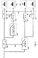
図6Aでは、表600は、各トランスデューサ内の減衰、遅延、及び位相シフトを具備する、図4で各トランスデューサが動作するような周波数範囲を要約する。図6B−6Eは、各範囲に対する動作フィルタ及び信号経路を示している。位相関係は、主トランスデューサに相対的に示されている。ここで、「+」は、各範囲に対する主トランスデューサを指示するとともに、「−」は、相殺トランスデューサを指示する。白色の背景を伴うトランスデューサ記号は、当該トランスデューサが、当該周波数範囲では非動作である(即ち、当該範囲内の信号は、当該トランスデューサへの入力外に実質的に減衰される)ことを指示している。表600及び図6B−6Eは、左入力204だけのフィルタを指示する。図示されていない対称表は、右入力502のフィルタを説明する。 In FIG. 6A, table 600 summarizes the frequency range in which each transducer operates in FIG. 4, with attenuation, delay, and phase shift within each transducer. 6B-6E show the operational filter and signal path for each range. The phase relationship is shown relative to the main transducer. Here, “+” indicates the main transducer for each range, and “−” indicates the cancellation transducer. A transducer symbol with a white background indicates that the transducer is inactive in the frequency range (ie, signals within the range are substantially attenuated outside the input to the transducer). Yes. Table 600 and FIGS. 6B-6E indicate a filter with only left input 204. A symmetric table, not shown, illustrates the filter for the right input 502.
550Hzより下の左チャネル信号に対しては、ロー602及び図6Bによって示されているように、左アレー100L内の両方の左トランスデューサ(外部トランスデューサ104及び内部トランスデューサ106)は動作するとともに、左外部トランスデューサ104のフィルタ302と左内部トランスデューサ106のフィルタ402とのために、互いに相対的に同位相(表100内の記号604,606)である。右アレー100R内の、2つの右トランスデューサ(外部110及び内部108)は動作するとともに、互いに相対的に位相が一致しているが、全体として、記号608,610によって示されているように、全体として、それらは、左トランスデューサと位相が一致していない。また、クロスフィードローパスフィルタ306から3dBの減衰がある。ローパスフィルタ404は、(既にフィルタ306によって反転された)低域周波数信号を、右内部トランスデューサに提供する。2つのアレーからのトランスデューサの出力のこの組み合わせは、所望の放射パターンを提供するとともに、ヌル軸114に沿ったヌルに対して責任を持つ。各アレーの2つのトランスデューサは、単一の音響ソースとして振舞うとともに、ソースの間隔は(個々のアレー構成要素の間の間隔とは反対に)アレーの間の間隔であり、それによって、この周波数範囲内の放射効率が増加するとともに、システムの最大出力性能も増加する。この構成とともに、2つのアレーは、単一の大きなアレーのように振舞う。
For left channel signals below 550 Hz, both left transducers (
左チャネル信号の550Hzから1kHzの範囲内では、ロー612及び図6Cによって示されているように、外部トランスデューサ104,110は、低い範囲(614,620)内で同一である一方、内部トランスデューサ106,108は、ローパスフィルタ402及び404及びハイパスフィルタ310及び312の組み合わせのために、オフ(616,618)である。外部トランスデューサ104及び110からの出力は、ヌル軸に沿ってヌルを形式し、それはヌル軸114であっても良い。この範囲では、2つのアレー100L,100Rは、また、低域周波数出力効率を増加する単一の大きいアレーとして振舞う。しかしながら、各アレーから1つのトランスデューサだけが、ハイパスフィルタ310及び312からの反転信号(実施例では、おおよそ1kHz)の干渉を回避するように動作する。ヌル軸に沿った音響ヌルは、もし所望するならば、種々のトランスデューサに適用される信号の間に遅延を導入することによって案内しても良い。
Within the 550 Hz to 1 kHz range of the left channel signal, the
左チャネル信号に対する1−3kHzの範囲内のヌル軸112に沿ったヌルは、ロー622及び図6D内で示されているように、左トランスデューサだけから生成される。左外部トランスデューサ104は、通常通りオンである(624)一方で、左内部トランスデューサ106は、ローパスフィルタ202によって、(システム最大出力を増加するために)減衰され、(ヌルを生成するために)位相反転される(626)とともに、(ヌル軸112を案内するために)遅延される。この周波数範囲では、ローパスフィルタ306のために、右トランスデューサ108,110の両方は、オフである(628,630)。この周波数範囲では、クロスフィードはない。
Nulls along the
ロー632及び図6E内で示されているような3kHzより上では、右トランスデューサ108、110は、オフに留まる(638,640)とともに、左内部トランスデューサ(106)も、フィルタ202によってターンオフされる(636)。左外部トランスデューサ104のみがオンに留まる(634)。
Above 3 kHz as shown in
概して、各々の個々のアレーのそれぞれの構成要素を、より高い周波数で当該アレーの放射パターンを独立に制御するように使用するとともに、両アレーを低域周波数で出力される組み合わされたアレーの放射パターンを制御する何らかの方式で共に使用することによって、低域周波数での効率が維持又は改善されうるとともに、指向性がより広い周波数範囲に亘って制御されうる。間隔が広げられたアレーは、システム全体の効率を改善するので、システムは、それ自身の側の信号を制御するために各アレーを使用するに過ぎないシステムと比較して、低域周波数でより多い出力を供給することが可能である。 In general, each component of each individual array is used to independently control the radiation pattern of the array at a higher frequency, and both arrays are emitted at a lower frequency. By using it together in some way to control the pattern, the efficiency at low frequencies can be maintained or improved and the directivity can be controlled over a wider frequency range. Widely spaced arrays improve overall system efficiency, so the system is better at lower frequencies compared to systems that only use each array to control its own side signals. It is possible to supply a lot of output.
上記で留意したように、任意の数のトランスデューサを具備するアレーを配置するのに、類似の技術を使用しても良い。フィルタすべき周波数、どの信号を反転、シフト又は遅延するか、及びトランスデューサの位置をどこにするかの詳細は、トランスデューサの数、トランスデューサの特徴、所望の出力、アレーを使用すべき環境、及び各々トランスデューサの出力特性のような要素に依存する。 As noted above, similar techniques may be used to place an array with any number of transducers. Details about the frequency to be filtered, which signal to invert, shift or delay, and where to position the transducer, number of transducers, transducer characteristics, desired output, environment in which the array should be used, and each transducer Depends on factors such as output characteristics.
他の実施形態は、特許請求の範囲の範囲内である。 Other embodiments are within the scope of the claims.
100L 左アレー
100R 右アレー
102 リスナ
103 リスニング環境
104 左外側
106 左内側
108 右内側
110 右外側
112 ヌル軸
114 ヌル軸
116 ヌル軸
118 左知覚軸
120 右知覚軸
Claims (43)
前記第1及び第2アレー(100L,100R)の前記トランスデューサ(104,106;108,110)に出力信号及びクロスフィード信号を提供するために入力信号(204,502)上で動作するフィルタ(202,304,306,310,312,314,402,404,504,506,514)と、
を具備し、
(a)前記第1アレー(100L)の複数のトランスデューサ(104,106)は、第1周波数範囲内で相殺的干渉を生成し、
(b)前記第1アレー(100L)の前記トランスデューサ(104,106)は、第2周波数範囲内で前記第1トランスデューサ(104)のみが動作し、かつ
(c)前記第1アレー(100L)の第1トランスデューサ(104)、及び前記第2アレー(100R)の第1トランスデューサ(110)は、第2周波数範囲内で相殺的干渉を生成することを特徴とする装置。First and second arrays (100L, 100R) of transducers (104, 106; 108, 110);
Filter (202) operating on input signals (204, 502) to provide output signals and cross-feed signals to the transducers (104, 106; 108, 110) of the first and second arrays (100L, 100R). 304,306,310,312,314,402,404,504,506,514),
Comprising
(A) a plurality of transducers (104, 106) of the first array (100L) generate destructive interference within a first frequency range;
(B) The transducers (104, 106) of the first array (100L) operate only in the first transducer (104) within a second frequency range, and (c) the transducers (104L) of the first array (100L). the first transducer (104), and the second first transducer array (100R) (110), the apparatus characterized by generating a destructive interference in the second frequency range.
直列接続され、前記第1アレー(100L)の第2トランスデューサ(106)に出力信号を提供する、前記高域周波数にコーナー周波数を具備する反転ローパスフィルタ(202)及び前記低域周波数にコーナー周波数を具備するハイパスフィルタ(310)と、
ハイパスフィルタ(310)と同位相にされるとともに、前記第1アレー(100L)の前記第1トランスデューサ(104)に出力信号を提供するオールパスフィルタ(302)と、
を具備することを特徴とする請求項1−6の1つ又は複数に記載の装置。The first frequency range comprises a frequency between a high frequency and a low frequency, and the filter is
An inverting low pass filter (202) having a corner frequency at the high frequency and a corner frequency at the low frequency, connected in series and providing an output signal to the second transducer (106) of the first array (100L) . A high-pass filter (310) comprising:
An all-pass filter (302) that is in phase with a high-pass filter (310) and provides an output signal to the first transducer ( 104 ) of the first array (100L);
7. Apparatus according to one or more of claims 1-6.
前記低域周波数でコーナー周波数を具備するとともに前記第2アレー(100R)にクロスフィード信号を提供するローパスフィルタ(306)と、
前記ローパスフィルタ(306)と同位相にされるとともに、前記第1アレー(100L)に出力信号を提供するオールパスフィルタ(304)と、
を具備することを特徴とする請求項9に記載の装置。The first frequency range comprises a frequency between a high frequency and a low frequency, and the filter is
A low pass filter (306) having a corner frequency at the low frequency and providing a cross feed signal to the second array (100R);
An all-pass filter (304) that is in phase with the low-pass filter (306) and provides an output signal to the first array (100L);
10. The apparatus according to claim 9, comprising:
前記高域周波数でコーナー周波数を具備するとともに、前記第2アレー(100R)にクロスフィード信号を提供する反転ローパスフィルタ(306)と、
前記反転ローパスフィルタ(306)と同位相にされるとともに、前記第1アレー(100L)に出力信号を提供するオールパスフィルタ(304)と、
を具備することを特徴とする請求項1−8の1つ又は複数に記載の装置。The second frequency range comprises a frequency below a first high frequency, and the filter
An inverting low pass filter (306) having a corner frequency at the high frequency and providing a cross feed signal to the second array (100R);
An all-pass filter (304) that is in phase with the inverting low-pass filter (306) and provides an output signal to the first array (100L);
9. An apparatus according to one or more of the preceding claims, characterized in that it comprises:
前記第1高域周波数でコーナー周波数を具備するとともに、前記第1アレー(100L)の前記第2トランスデューサ(106)に出力信号を提供する第1ハイパスフィルタ(310)と、
前記ハイパスフィルタ(310)と同位相にされるとともに、前記第1アレー(100L)の前記第1トランスデューサ(104)に出力信号を提供する第1オールパスフィルタ(302)と、
前記第1オールパスフィルタ(302)と同位相にされるとともに、前記第2アレー(100R)の前記第1トランスデューサ(110)にクロスフィード信号を提供する第2オールパスフィルタ(314)と、
を具備することを特徴とする請求項12に記載の装置。The second frequency range comprises a frequency below a first high frequency, and the filter
A first high pass filter (310) having a corner frequency at the first high frequency and providing an output signal to the second transducer ( 106 ) of the first array (100L);
A first all-pass filter (302) that is in phase with the high-pass filter (310) and provides an output signal to the first transducer ( 104 ) of the first array (100L);
A second all-pass filter (314) that is in phase with the first all-pass filter (302) and provides a cross-feed signal to the first transducer ( 110 ) of the second array (100R);
The apparatus according to claim 12, comprising:
前記第1高域周波数でコーナー周波数を具備するとともに、前記第2アレー(100R)の第2トランスデューサ(108)にクロスフィード信号を提供するとともに、前記第2オールパスフィルタ(314)と同位相にされた第2ハイパスフィルタ(312)をさらに具備することを特徴とする請求項13に記載の装置。The filter is
The first high frequency has a corner frequency, provides a cross-feed signal to the second transducer ( 108 ) of the second array (100R), and is in phase with the second all-pass filter (314). 14. The apparatus of claim 13, further comprising a second high pass filter (312).
前記第2高域周波数にコーナー周波数を具備するとともに、前記第1及び第2アレー(100L,100R)の各々の前記第2トランスデューサ(106;108)に、それぞれ、出力信号及びクロスフィード信号を提供する第1及び第2ローパスフィルタ(402,404)と、
前記第1及び第2ローパスフィルタ(402,404)にそれぞれ、及び互いに、位相が一致するとともに、それぞれ、第1及び第2アレー(100L,100R)の各々の前記第1トランスデューサ(104;110)に、それぞれ出力信号及びクロスフィード信号を提供する第1及び第2オールパスフィルタ(302,314)と、
を具備することを特徴とする請求項15に記載の装置。The filter is
The second high-frequency has a corner frequency, and provides an output signal and a cross-feed signal to the second transducers ( 106; 108 ) of the first and second arrays (100L, 100R), respectively. First and second low pass filters (402, 404),
The first and second low-pass filters (402, 404) and the first transducer ( 104; 110 ) of each of the first and second arrays (100L, 100R) are in phase with each other and are in phase with each other. First and second all-pass filters (302, 314) for providing an output signal and a cross-feed signal, respectively,
The apparatus of claim 15, comprising:
(d)第3周波数範囲内では、前記第1アレー(100L)の前記第1トランスデューサ(104)のみが動作する
ように出力信号及びクロスフィード信号を提供することを特徴とする請求項1−6の1つ又は複数に記載の装置。The filter is also connected to the transducers (104, 106; 108, 110) of the first and second arrays (100L, 100R).
(D) providing an output signal and a cross-feed signal so that only the first transducer (104) of the first array (100L) operates within a third frequency range; 6. The device according to one or more of the above.
前記低域周波数でコーナー周波数を具備するとともに、前記第1アレー(100L)の前記第2トランスデューサ(106)に出力信号を提供するローパスフィルタ(202)
を具備することを特徴とする請求項17−20の1つ又は複数に記載の装置。The filter is
A low pass filter (202) having a corner frequency at the low frequency and providing an output signal to the second transducer ( 106 ) of the first array (100L)
21. Apparatus according to one or more of the claims 17-20.
前記低域周波数にコーナー周波数を具備するとともに、前記第1アレー(100L)の前記第2トランスデューサ(106)に出力信号を提供する第1ローパスフィルタ(202)と、
前記低域周波数に又はそれより下にコーナー周波数を具備するとともに、前記第2アレー(100R)にクロスフィード信号を提供する第2ローパスフィルタ(306)と、
前記第2ローパスフィルタ(306)と同位相にされるとともに、前記第1アレー(100L)に出力信号を提供するオールパスフィルタ(304)と、
を具備することを特徴とする請求項22に記載の装置。The filter is
A first low pass filter (202) having a corner frequency at the low frequency and providing an output signal to the second transducer ( 106 ) of the first array (100L);
A second low pass filter (306) having a corner frequency at or below the low frequency and providing a cross feed signal to the second array (100R);
An all-pass filter (304) that is in phase with the second low-pass filter (306) and provides an output signal to the first array (100L);
23. The apparatus of claim 22, comprising:
前記第1アレー(100L)の第1合計入力に出力信号を提供する第3オールパスフィルタ(304)と、
前記第1アレー(100L)の前記第1トランスデューサ(104)への入力に、出力信号を提供する第1オールパスフィルタ(302)と、
前記第1アレー(100L)の前記第2トランスデューサ(106)への第1合計入力に出力信号を提供する、直列接続された第1ローパスフィルタ(202)及び第1ハイパスフィルタ(310)と、
前記第1アレー(100L)の前記第2トランスデューサ(106)への第2合計入力に出力信号を提供する第3ローパスフィルタ(404)と、
クロスフィード信号を、前記第2アレー(100R)の第1合計入力に提供する第2ローパスフィルタ(306)と、
前記第2アレー(100R)の前記第1トランスデューサ(110)への入力に、クロスフィード信号を提供する第2オールパスフィルタ(314)と、
前記第2アレー(100R)の前記第2トランスデューサ(108)への第1合計入力にクロスフィード信号を提供するとともに直列接続された第4ローパスフィルタ(514)及び第2ハイパスフィルタ(312)と、
前記第2アレー(100R)の前記第2トランスデューサ(108)への第2合計入力にクロスフィード信号を提供する第5ローパスフィルタ(402)と、
を具備する請求項17−20の1つ又は複数に記載の装置。The filter is
A third all-pass filter (304) for providing an output signal to a first sum input of the first array (100L);
A first all-pass filter (302) that provides an output signal to an input to the first transducer ( 104 ) of the first array (100L);
A first low pass filter (202) and a first high pass filter (310) connected in series to provide an output signal to a first sum input to the second transducer ( 106 ) of the first array (100L);
A third low pass filter (404) for providing an output signal to a second sum input to the second transducer ( 106 ) of the first array (100L);
A second low pass filter (306) for providing a cross-feed signal to a first sum input of the second array (100R);
A second all-pass filter (314) that provides a cross-feed signal at the input to the first transducer ( 110 ) of the second array (100R);
A fourth low-pass filter (514) and a second high-pass filter (312) connected in series and providing a cross-feed signal to a first sum input to the second transducer ( 108 ) of the second array (100R);
A fifth low pass filter (402) that provides a cross-feed signal to a second sum input to the second transducer ( 108 ) of the second array (100R);
21. Apparatus according to one or more of the claims 17-20.
前記第2ローパスフィルタ(306)及び前記第1及び第2ハイパスフィルタ(310,312)は、中間域周波数にコーナー周波数を具備し、かつ、
第1及び第4ローパスフィルタ(202,514)は、高域周波数にコーナー周波数を具備することを特徴とする請求項24に記載の装置。The third and fifth low pass filters (404, 402) have a low frequency and a corner frequency,
The second low-pass filter (306) and the first and second high-pass filters (310, 312) have a corner frequency at an intermediate frequency, and
25. The apparatus of claim 24, wherein the first and fourth low pass filters (202, 514) comprise a corner frequency at a high frequency.
前記第1アレー(100L)の第2合計入力にクロスフィード信号を提供する第6ローパスフィルタ(506)と、
前記第2アレー(100R)の第2合計入力に出力信号を提供する第4オールパスフィルタ(504)と、
をさらに具備するとともに、
第1信号入力は、前記第3オールパスフィルタ(304)及び前記第2ローパスフィルタ(306)に接続されるとともに、
第2信号入力は、前記第4オールパスフィルタ(504)及び前記第6ローパスフィルタ(506)に接続されることを特徴とする請求項24又は25に記載の装置。The filter is
A sixth low pass filter (506) for providing a cross feed signal to a second sum input of the first array (100L);
A fourth all-pass filter (504) for providing an output signal to a second sum input of the second array (100R);
And further comprising
The first signal input is connected to the third all-pass filter (304) and the second low-pass filter (306),
26. Device according to claim 24 or 25, characterized in that a second signal input is connected to the fourth all-pass filter (504) and the sixth low-pass filter (506).
(d)前記第1アレー(100L)の前記トランスデューサ(104,106)は、追加周波数範囲内で単一の音響ソースとして振舞い、
(e)前記第1アレー(100L)の複数のトランスデューサ(104,106)、及び前記第2アレー(100R)の複数のトランスデューサ(108,110)は、前記追加周波数範囲内で相殺的干渉を生成する
ように、出力信号及びクロスフィード信号を提供することを特徴とする請求項1に記載の装置。The filter is also connected to the transducers (104, 106; 108, 110) of the first and second arrays (100L, 100R).
(D) the transducers (104, 106) of the first array (100L) behave as a single acoustic source within an additional frequency range;
(E) The plurality of transducers (104, 106) of the first array (100L) and the plurality of transducers (108, 110) of the second array (100R) generate destructive interference within the additional frequency range. The apparatus of claim 1, wherein the apparatus provides an output signal and a cross-feed signal.
(d)前記第2アレー(100R)の複数のトランスデューサ(108,110)は、前記第1周波数範囲内で相殺的干渉を生成し、
(e)前記第2アレー(100R)の前記トランスデューサ(104,106)は、前記第2周波数範囲内で前記第1トランスデューサ(104)のみが動作し、かつ
(c)で、前記第1アレー(100L)の前記第1トランスデューサ(104)、及び前記第2アレー(100R)の前記第1トランスデューサ(110)は、前記第2周波数範囲内の前記第1入力信号及び前記第2入力信号の両方をベースとして、相殺的干渉を生成するように、出力信号及びクロスフィード信号を提供するように第2入力信号上で動作することを特徴とする請求項1に記載の装置。The filter is also connected to the transducers (108, 110; 104, 106) of the second and first arrays (100R, 100L),
(D) a plurality of transducers (108, 110) of the second array (100R) generate destructive interference within the first frequency range;
(E) For the transducers (104, 106) of the second array (100R), only the first transducer (104) operates within the second frequency range, and in (c), the first array ( wherein the first transducer 100L) (104), and both said second said first transducer array (100R) (110), said first input signal and the second input signal in said second frequency range The apparatus of claim 1, wherein the apparatus operates on the second input signal to provide an output signal and a cross-feed signal to generate destructive interference as a base.
(d)前記第1アレー(100L)の前記トランスデューサ(104,106)は、前記第1及び第2周波数範囲内で、それぞれ、実質的に異なる角度の相殺的干渉を生成する
ように、前記第1及び第2アレー(100L,100R)の前記トランスデューサ(104,106;108,110)に出力信号及びクロスフィード信号を提供するように、入力信号(204,502)上で動作し、
前記第1アレーを駆動する第1信号と前記第2アレーを駆動する第2信号とは同一でないことを特徴とする請求項1に記載の装置。The filter (202, 304, 306, 310, 312, 314, 402, 404, 504, 506, 514)
(D) the transducers (104, 106) of the first array (100L) are configured to generate destructive interference at substantially different angles within the first and second frequency ranges, respectively. Operating on input signals (204, 502) to provide output signals and cross-feed signals to the transducers (104, 106; 108, 110) of the first and second arrays (100L, 100R);
The apparatus of claim 1, wherein the first signal driving the first array and the second signal driving the second array are not the same.
(b)前記第1アレー(100L)のトランスデューサ(104,106)は、第2周波数範囲で前記第1トランスデューサ(104)のみが動作し、かつ
(c)前記第1アレー(100L)の第1トランスデューサ(104)及び前記第2アレー(100R)の第1トランスデューサ(110)が、前記第2周波数範囲内で相殺的干渉を生成する
ように入力信号をフィルタするとともに、前記第1及び第2アレー(100L,100R)のトランスデューサ(104,106;108,110)を駆動するために、フィルタされた前記信号を、出力信号及びクロスフィード信号として、物理的に離間されたトランスデューサの第1及び第2アレー(100L,100R)に分配する段階と、
を具備することを特徴とする方法。(A) the transducers (104, 106) of the first array (100L) generate destructive interference within a first frequency range;
(B) The transducer (104, 106) of the first array (100L) operates only in the first transducer (104) in the second frequency range, and (c) the first of the first array (100L). A transducer ( 104 ) and a first transducer ( 110 ) of the second array (100R) filter the input signal to produce destructive interference within the second frequency range, and the first and second arrays In order to drive the (100L, 100R) transducers (104, 106; 108, 110), the filtered signals are used as output signals and cross-feed signals as first and second physically spaced transducers. Distributing to the arrays (100L, 100R);
A method comprising the steps of:
(d)第3周波数範囲内では、前記第1アレー(100L)の前記第1トランスデューサ(104)のみが動作する
ように、前記第1及び第2アレー(100L,100R)のトランスデューサ(104,106;108,110)を駆動することを特徴とする請求項33−38の1つ又は複数に記載の方法。The output signal and cross-feed signal are also
(D) Within the third frequency range, only the first transducer (104L) of the first array (100L) operates so that the transducers (104,100R) of the first and second arrays (100L, 100R) are operated . 106; 108, 110). Method according to one or more of claims 33-38.
(d)前記第1アレー(100L)のトランスデューサ(104,106)は、追加周波数範囲で単一の音響ソースとして振舞い、かつ
(e)前記第1アレー(100L)のトランスデューサ(104,106)、及び前記第2アレー(100R)のトランスデューサ(108,110)は、前記追加周波数範囲内で相殺的干渉を生成する
ように、前記第1及び第2アレー(100L,100R)のトランスデューサ(104,106;108,110)を駆動することを特徴とする請求項33−38の1つ又は複数に記載の方法。The output signal and cross-feed signal are also
(D) the transducer (104, 106) of the first array (100L) behaves as a single acoustic source in the additional frequency range; and (e) the transducer (104, 106) of the first array (100L); And the transducers (108, 110) of the second array (100R) to generate destructive interference within the additional frequency range, the transducers (104, 106) of the first and second arrays (100L, 100R). 108, 110). 41. A method according to one or more of claims 33-38.
Applications Claiming Priority (3)
| Application Number | Priority Date | Filing Date | Title |
|---|---|---|---|
| US11/462,496 US7995778B2 (en) | 2006-08-04 | 2006-08-04 | Acoustic transducer array signal processing |
| US11/462,496 | 2006-08-04 | ||
| PCT/US2007/074618 WO2008019231A2 (en) | 2006-08-04 | 2007-07-27 | Acoustic transducer array signal processing |
Publications (2)
| Publication Number | Publication Date |
|---|---|
| JP2009545928A JP2009545928A (en) | 2009-12-24 |
| JP5180207B2 true JP5180207B2 (en) | 2013-04-10 |
Family
ID=38921819
Family Applications (1)
| Application Number | Title | Priority Date | Filing Date |
|---|---|---|---|
| JP2009522977A Expired - Fee Related JP5180207B2 (en) | 2006-08-04 | 2007-07-27 | Acoustic transducer array signal processing |
Country Status (9)
| Country | Link |
|---|---|
| US (1) | US7995778B2 (en) |
| EP (1) | EP2047456B1 (en) |
| JP (1) | JP5180207B2 (en) |
| CN (1) | CN101351836B (en) |
| AT (1) | ATE470216T1 (en) |
| AU (1) | AU2007281813A1 (en) |
| DE (1) | DE602007006960D1 (en) |
| HK (1) | HK1125733A1 (en) |
| WO (1) | WO2008019231A2 (en) |
Cited By (1)
| Publication number | Priority date | Publication date | Assignee | Title |
|---|---|---|---|---|
| JP7008380B1 (en) | 2021-09-01 | 2022-01-25 | 株式会社フジケンプラス | Fixture |
Families Citing this family (19)
| Publication number | Priority date | Publication date | Assignee | Title |
|---|---|---|---|---|
| US8019091B2 (en) | 2000-07-19 | 2011-09-13 | Aliphcom, Inc. | Voice activity detector (VAD) -based multiple-microphone acoustic noise suppression |
| US8280072B2 (en) | 2003-03-27 | 2012-10-02 | Aliphcom, Inc. | Microphone array with rear venting |
| US9066186B2 (en) | 2003-01-30 | 2015-06-23 | Aliphcom | Light-based detection for acoustic applications |
| US9099094B2 (en) | 2003-03-27 | 2015-08-04 | Aliphcom | Microphone array with rear venting |
| US9100748B2 (en) * | 2007-05-04 | 2015-08-04 | Bose Corporation | System and method for directionally radiating sound |
| US8483413B2 (en) * | 2007-05-04 | 2013-07-09 | Bose Corporation | System and method for directionally radiating sound |
| US20080273724A1 (en) * | 2007-05-04 | 2008-11-06 | Klaus Hartung | System and method for directionally radiating sound |
| KR101385839B1 (en) * | 2007-09-21 | 2014-04-16 | 삼성전자주식회사 | Speaker apparatus of mobile communication terminal for outputting high quality sound |
| US7957412B2 (en) * | 2008-03-19 | 2011-06-07 | Cray Inc. | Lonely pulse compensation |
| US9264813B2 (en) * | 2010-03-04 | 2016-02-16 | Logitech, Europe S.A. | Virtual surround for loudspeakers with increased constant directivity |
| US8934647B2 (en) * | 2011-04-14 | 2015-01-13 | Bose Corporation | Orientation-responsive acoustic driver selection |
| CN105050003B (en) * | 2011-04-14 | 2018-05-25 | 伯斯有限公司 | The acoustic driver operation of orientation response formula |
| US9253561B2 (en) * | 2011-04-14 | 2016-02-02 | Bose Corporation | Orientation-responsive acoustic array control |
| US8934655B2 (en) * | 2011-04-14 | 2015-01-13 | Bose Corporation | Orientation-responsive use of acoustic reflection |
| WO2015086040A1 (en) * | 2013-12-09 | 2015-06-18 | Huawei Technologies Co., Ltd. | Apparatus and method for enhancing a spatial perception of an audio signal |
| TWI657701B (en) * | 2016-06-17 | 2019-04-21 | 中國商信泰光學(深圳)有限公司 | Headphone device |
| GB2589091B (en) * | 2019-11-15 | 2022-01-12 | Meridian Audio Ltd | Spectral compensation filters for close proximity sound sources |
| US11323813B2 (en) * | 2020-09-30 | 2022-05-03 | Bose Corporation | Soundbar |
| US20230370805A1 (en) * | 2022-05-11 | 2023-11-16 | Harman International Industries, Incorporated | Techniques for outputting audio through a plurality of drivers within a same audio output device |
Family Cites Families (25)
| Publication number | Priority date | Publication date | Assignee | Title |
|---|---|---|---|---|
| US4569074A (en) * | 1984-06-01 | 1986-02-04 | Polk Audio, Inc. | Method and apparatus for reproducing sound having a realistic ambient field and acoustic image |
| US4819269A (en) * | 1987-07-21 | 1989-04-04 | Hughes Aircraft Company | Extended imaging split mode loudspeaker system |
| US4893342A (en) * | 1987-10-15 | 1990-01-09 | Cooper Duane H | Head diffraction compensated stereo system |
| JPH01144719A (en) * | 1987-11-30 | 1989-06-07 | Toshiba Corp | Retriggable multi-vibrator |
| US4847904A (en) * | 1988-04-01 | 1989-07-11 | Boston Acoustics, Inc. | Ambient imaging loudspeaker system |
| US4888804A (en) * | 1988-05-12 | 1989-12-19 | Gefvert Herbert I | Sound reproduction system |
| US5027403A (en) * | 1988-11-21 | 1991-06-25 | Bose Corporation | Video sound |
| JP2528178B2 (en) * | 1989-03-14 | 1996-08-28 | パイオニア株式会社 | Directional speaker device |
| US5121433A (en) * | 1990-06-15 | 1992-06-09 | Auris Corp. | Apparatus and method for controlling the magnitude spectrum of acoustically combined signals |
| US5870484A (en) * | 1995-09-05 | 1999-02-09 | Greenberger; Hal | Loudspeaker array with signal dependent radiation pattern |
| US6263083B1 (en) * | 1997-04-11 | 2001-07-17 | The Regents Of The University Of Michigan | Directional tone color loudspeaker |
| GB9716412D0 (en) * | 1997-08-05 | 1997-10-08 | New Transducers Ltd | Sound radiating devices/systems |
| US7164768B2 (en) * | 2001-06-21 | 2007-01-16 | Bose Corporation | Audio signal processing |
| GB0203895D0 (en) * | 2002-02-19 | 2002-04-03 | 1 Ltd | Compact surround-sound system |
| US7676047B2 (en) * | 2002-12-03 | 2010-03-09 | Bose Corporation | Electroacoustical transducing with low frequency augmenting devices |
| US20040105550A1 (en) * | 2002-12-03 | 2004-06-03 | Aylward J. Richard | Directional electroacoustical transducing |
| US8139797B2 (en) * | 2002-12-03 | 2012-03-20 | Bose Corporation | Directional electroacoustical transducing |
| US7519188B2 (en) * | 2003-09-18 | 2009-04-14 | Bose Corporation | Electroacoustical transducing |
| JP4114584B2 (en) * | 2003-09-25 | 2008-07-09 | ヤマハ株式会社 | Directional speaker control system |
| GB0405346D0 (en) | 2004-03-08 | 2004-04-21 | 1 Ltd | Method of creating a sound field |
| US7346315B2 (en) * | 2004-03-30 | 2008-03-18 | Motorola Inc | Handheld device loudspeaker system |
| US7561706B2 (en) * | 2004-05-04 | 2009-07-14 | Bose Corporation | Reproducing center channel information in a vehicle multichannel audio system |
| JP2006115396A (en) * | 2004-10-18 | 2006-04-27 | Sony Corp | Reproduction method of audio signal and reproducing apparatus therefor |
| KR100958243B1 (en) * | 2006-03-15 | 2010-05-17 | 돌비 레버러토리즈 라이쎈싱 코오포레이션 | Stereophonic Sound Imaging |
| US8238588B2 (en) * | 2006-12-18 | 2012-08-07 | Meyer Sound Laboratories, Incorporated | Loudspeaker system and method for producing synthesized directional sound beam |
-
2006
- 2006-08-04 US US11/462,496 patent/US7995778B2/en active Active
-
2007
- 2007-07-27 JP JP2009522977A patent/JP5180207B2/en not_active Expired - Fee Related
- 2007-07-27 DE DE602007006960T patent/DE602007006960D1/en active Active
- 2007-07-27 WO PCT/US2007/074618 patent/WO2008019231A2/en active Application Filing
- 2007-07-27 EP EP07840560A patent/EP2047456B1/en active Active
- 2007-07-27 AU AU2007281813A patent/AU2007281813A1/en not_active Abandoned
- 2007-07-27 CN CN2007800010389A patent/CN101351836B/en not_active Expired - Fee Related
- 2007-07-27 AT AT07840560T patent/ATE470216T1/en not_active IP Right Cessation
-
2009
- 2009-05-19 HK HK09104577.4A patent/HK1125733A1/en not_active IP Right Cessation
Cited By (1)
| Publication number | Priority date | Publication date | Assignee | Title |
|---|---|---|---|---|
| JP7008380B1 (en) | 2021-09-01 | 2022-01-25 | 株式会社フジケンプラス | Fixture |
Also Published As
| Publication number | Publication date |
|---|---|
| US7995778B2 (en) | 2011-08-09 |
| EP2047456A2 (en) | 2009-04-15 |
| CN101351836A (en) | 2009-01-21 |
| HK1125733A1 (en) | 2009-08-14 |
| AU2007281813A1 (en) | 2008-02-14 |
| ATE470216T1 (en) | 2010-06-15 |
| US20080031474A1 (en) | 2008-02-07 |
| DE602007006960D1 (en) | 2010-07-15 |
| JP2009545928A (en) | 2009-12-24 |
| WO2008019231A3 (en) | 2008-03-20 |
| WO2008019231A2 (en) | 2008-02-14 |
| EP2047456B1 (en) | 2010-06-02 |
| CN101351836B (en) | 2012-09-05 |
Similar Documents
| Publication | Publication Date | Title |
|---|---|---|
| JP5180207B2 (en) | Acoustic transducer array signal processing | |
| KR100922910B1 (en) | Method and apparatus to create a sound field | |
| US8325941B2 (en) | Method and apparatus to shape sound | |
| US7606377B2 (en) | Method and system for surround sound beam-forming using vertically displaced drivers | |
| KR101292206B1 (en) | Array speaker system and the implementing method thereof | |
| JP4114584B2 (en) | Directional speaker control system | |
| EP1631114B1 (en) | Array speaker system | |
| KR101524463B1 (en) | Method and apparatus for focusing the sound through the array speaker | |
| JP2004194315A5 (en) | ||
| WO2005051041A1 (en) | Array speaker device | |
| WO2010132397A1 (en) | Center channel rendering | |
| US20100142733A1 (en) | Apparatus and Method for Generating Directional Sound | |
| JP2006238155A (en) | Array speaker apparatus | |
| EP3195614A1 (en) | Loudspeaker with narrow dispersion | |
| US20220159397A1 (en) | Active Cancellation of a Height-Channel Soundbar Array's Forward Sound Radiation | |
| GB2373956A (en) | Method and apparatus to create a sound field | |
| WO2011161567A1 (en) | A sound reproduction system and method and driver therefor | |
| CN110312198B (en) | Virtual sound source repositioning method and device for digital cinema | |
| JP4625756B2 (en) | Loudspeaker array system | |
| WO2020102183A1 (en) | Loudspeaker system with overhead sound image generating elevation module | |
| EP1802163A1 (en) | Loudspeaker array system | |
| JP2010200349A (en) | Array system for loudspeaker |
Legal Events
| Date | Code | Title | Description |
|---|---|---|---|
| A621 | Written request for application examination |
Free format text: JAPANESE INTERMEDIATE CODE: A621 Effective date: 20100407 |
|
| A131 | Notification of reasons for refusal |
Free format text: JAPANESE INTERMEDIATE CODE: A131 Effective date: 20120124 |
|
| A601 | Written request for extension of time |
Free format text: JAPANESE INTERMEDIATE CODE: A601 Effective date: 20120424 |
|
| A602 | Written permission of extension of time |
Free format text: JAPANESE INTERMEDIATE CODE: A602 Effective date: 20120502 |
|
| A521 | Request for written amendment filed |
Free format text: JAPANESE INTERMEDIATE CODE: A523 Effective date: 20120523 |
|
| TRDD | Decision of grant or rejection written | ||
| A01 | Written decision to grant a patent or to grant a registration (utility model) |
Free format text: JAPANESE INTERMEDIATE CODE: A01 Effective date: 20121211 |
|
| A61 | First payment of annual fees (during grant procedure) |
Free format text: JAPANESE INTERMEDIATE CODE: A61 Effective date: 20130110 |
|
| R150 | Certificate of patent or registration of utility model |
Ref document number: 5180207 Country of ref document: JP Free format text: JAPANESE INTERMEDIATE CODE: R150 |
|
| R250 | Receipt of annual fees |
Free format text: JAPANESE INTERMEDIATE CODE: R250 |
|
| R250 | Receipt of annual fees |
Free format text: JAPANESE INTERMEDIATE CODE: R250 |
|
| R250 | Receipt of annual fees |
Free format text: JAPANESE INTERMEDIATE CODE: R250 |
|
| R250 | Receipt of annual fees |
Free format text: JAPANESE INTERMEDIATE CODE: R250 |
|
| LAPS | Cancellation because of no payment of annual fees |