JP5178497B2 - Image reading apparatus, image reading apparatus control method, and program - Google Patents
Image reading apparatus, image reading apparatus control method, and program Download PDFInfo
- Publication number
- JP5178497B2 JP5178497B2 JP2008327910A JP2008327910A JP5178497B2 JP 5178497 B2 JP5178497 B2 JP 5178497B2 JP 2008327910 A JP2008327910 A JP 2008327910A JP 2008327910 A JP2008327910 A JP 2008327910A JP 5178497 B2 JP5178497 B2 JP 5178497B2
- Authority
- JP
- Japan
- Prior art keywords
- image
- image data
- divided
- size
- dividing
- Prior art date
- Legal status (The legal status is an assumption and is not a legal conclusion. Google has not performed a legal analysis and makes no representation as to the accuracy of the status listed.)
- Expired - Fee Related
Links
- 238000000034 method Methods 0.000 title claims description 47
- 230000008569 process Effects 0.000 claims description 32
- 238000006243 chemical reaction Methods 0.000 claims description 14
- 238000005192 partition Methods 0.000 claims 1
- 238000012545 processing Methods 0.000 description 37
- 230000006870 function Effects 0.000 description 10
- 230000005540 biological transmission Effects 0.000 description 6
- 238000010586 diagram Methods 0.000 description 6
- 230000011218 segmentation Effects 0.000 description 4
- 230000009467 reduction Effects 0.000 description 3
- 230000003796 beauty Effects 0.000 description 1
- 230000006835 compression Effects 0.000 description 1
- 238000007906 compression Methods 0.000 description 1
- 238000007796 conventional method Methods 0.000 description 1
- 238000012937 correction Methods 0.000 description 1
- 230000006837 decompression Effects 0.000 description 1
- 230000004044 response Effects 0.000 description 1
- 238000005549 size reduction Methods 0.000 description 1
Images


Classifications
-
- H—ELECTRICITY
- H04—ELECTRIC COMMUNICATION TECHNIQUE
- H04N—PICTORIAL COMMUNICATION, e.g. TELEVISION
- H04N1/00—Scanning, transmission or reproduction of documents or the like, e.g. facsimile transmission; Details thereof
- H04N1/32—Circuits or arrangements for control or supervision between transmitter and receiver or between image input and image output device, e.g. between a still-image camera and its memory or between a still-image camera and a printer device
- H04N1/32358—Circuits or arrangements for control or supervision between transmitter and receiver or between image input and image output device, e.g. between a still-image camera and its memory or between a still-image camera and a printer device using picture signal storage, e.g. at transmitter
- H04N1/32363—Circuits or arrangements for control or supervision between transmitter and receiver or between image input and image output device, e.g. between a still-image camera and its memory or between a still-image camera and a printer device using picture signal storage, e.g. at transmitter at the transmitter or at the receiver
- H04N1/32379—Functions of a still picture terminal memory associated with reception
-
- H—ELECTRICITY
- H04—ELECTRIC COMMUNICATION TECHNIQUE
- H04N—PICTORIAL COMMUNICATION, e.g. TELEVISION
- H04N2201/00—Indexing scheme relating to scanning, transmission or reproduction of documents or the like, and to details thereof
- H04N2201/32—Circuits or arrangements for control or supervision between transmitter and receiver or between image input and image output device, e.g. between a still-image camera and its memory or between a still-image camera and a printer device
- H04N2201/3285—Circuits or arrangements for control or supervision between transmitter and receiver or between image input and image output device, e.g. between a still-image camera and its memory or between a still-image camera and a printer device using picture signal storage, e.g. at transmitter
- H04N2201/3298—Checking or indicating the storage space
Description
本発明は、スキャナなど画像読み取り装置、及び画像読み取り装置の制御方法、並びに前記制御方法を実現するためのプログラムに関する。 The present invention relates to an image reading apparatus such as a scanner, a control method for the image reading apparatus, and a program for realizing the control method.
従来より、画像処理装置では、複数の静止画像を纏めて同一のファイルに記録したフォーマットを出力することが広く行われている。例えば、特許文献1では、出力順序をフォーマットのヘッダに記載し、再生時にこのフォーマットのヘッダ情報を基に静止画像の再生順序を決定する方法が提案されている。
しかしながら、上記の従来の技術では、次のような問題点があった。 However, the above conventional techniques have the following problems.
複数の静止画像を同一ファイルに纏めて出力する場合に、画像のサイズが大きいと、画像処理装置が搭載するメモリの容量によっては、処理する画像データをメモリに展開することができない場合がある。 When a plurality of still images are output together in the same file, if the size of the image is large, the image data to be processed may not be developed in the memory depending on the capacity of the memory installed in the image processing apparatus.
これを解決するため、搭載するメモリの容量を増やすことが考えられるが、これでは、画像形成装置の低コスト化に支障を来すという問題があった。 In order to solve this, it is conceivable to increase the capacity of the memory to be mounted. However, this has a problem in that the cost of the image forming apparatus is reduced.
本発明は上記従来の問題点に鑑み、次のような、画像読み取り装置、及び画像読み取り装置の制御方法、並びにプログラムを提供することを目的とする。即ち、読み取った画像データのサイズが大きくても、ワークメモリの容量を増やすことなく、該画像データの画像処理を行うことができるようにする。 The present invention is the light of the conventional problems, such as the following, and an object thereof is to provide an image reading equipment, the control method 及 beauty image reading apparatus, and a program. That is, even if the size of the read image data is large, the image data can be processed without increasing the capacity of the work memory.
上記目的を達成するために、本発明の画像読み取り装置は、画像読み取り手段が原稿を読み取って生成した画像データを記憶するためのワークメモリと、前記読み取られた画像データのサイズが前記ワークメモリ内で前記画像データを格納するための領域のサイズよりも大きい場合に、該画像データを分割する分割手段と、前記分割手段により分割された複数の分割画像データのうちの1つを前記ワークメモリに格納し、前記ワークメモリに格納された分割画像データを所定のフォーマットに変換する処理を、前記分割された複数の分割画像データの各々に対して行う変換手段と、前記変換手段により前記所定のフォーマットに変換された複数の分割画像データから1つの画像ファイルを生成する画像ファイル生成手段と、前記所定のフォーマットに変換された複数の分割画像データの各々に対して、レイアウト情報を含んだヘッダ情報を付与する付与手段と、を有することを特徴とする。 In order to achieve the above object, an image reading apparatus according to the present invention includes a work memory for storing image data generated by reading an original by an image reading unit, and the size of the read image data in the work memory. when in larger than the size of the area for storing the image data, dividing means for dividing the image data, one of a plurality of divided image data divided by said dividing means to the work memory storing, processing for converting the divided image data stored in the work memory in a predetermined format, and converting means for performing for each of said divided plurality of divided image data, wherein the predetermined format by the converting means and image file generating means for generating a single image file from the plurality of divided image data converted into the predetermined Four For each of a plurality of divided image data converted into Tsu bets, and having a providing means for providing the header information including the layout information.
上記目的を達成するために、本発明の画像読み取り装置の制御方法は、画像を読み取る画像読み取り装置の制御方法であって、画像読み取り手段が原稿を読み取って生成した画像データのサイズがワークメモリ内で前記画像データを格納するための領域のサイズよりも大きい場合に、該画像データを分割する分割工程と、前記分割工程で分割された複数の分割画像データのうちの1つを前記ワークメモリに格納し、前記ワークメモリに格納された分割画像データを所定のフォーマットに変換する処理を、前記分割された複数の分割画像データの各々に対して行う変換工程と、前記変換工程で前記所定のフォーマットに変換された複数の分割画像データから1つの画像ファイルを生成する画像ファイル生成工程と、前記所定のフォーマットに変換された複数の分割画像データの各々に対して、レイアウト情報を含んだヘッダ情報を付与する付与工程と、を有することを特徴とする。 In order to achieve the above object, an image reading apparatus control method according to the present invention is an image reading apparatus control method for reading an image, and the size of image data generated by reading an original by an image reading means is within a work memory. When the image data is larger than the size of the area for storing the image data, a division step for dividing the image data and one of the plurality of divided image data divided in the division step are stored in the work memory. A conversion step of storing and converting the divided image data stored in the work memory into a predetermined format for each of the plurality of divided divided image data; and the predetermined format in the conversion step and an image file generating step of generating a single image file from the plurality of divided image data converted into, varying the predetermined format For each of a plurality of divided image data, characterized by having a a step of applying the header information including the layout information.
上記目的を達成するために、本発明のプログラムは、画像を読み取る画像読み取り装置の制御方法を実行するための、コンピュータで読み取り可能なプログラムであって、画像読み取り手段が原稿を読み取って生成した画像データのサイズがワークメモリ内で前記画像データを格納するための領域のサイズよりも大きい場合に、該画像データを分割する分割ステップと、前記分割ステップで分割された複数の分割画像データのうちの1つを前記ワークメモリに格納し、前記ワークメモリに格納された分割画像データを所定のフォーマットに変換する処理を、前記分割された複数の分割画像データの各々に対して行う変換ステップと、前記変換ステップで前記所定のフォーマットに変換された複数の分割画像データから1つの画像ファイルを生成する画像ファイル生成ステップと、前記所定のフォーマットに変換された複数の分割画像データの各々に対して、レイアウト情報を含んだヘッダ情報を付与する付与ステップと、を有することを特徴とする。 In order to achieve the above object, a program of the present invention is a computer-readable program for executing a control method of an image reading apparatus for reading an image, and an image generated by reading an original by an image reading unit. If the size of the data is larger than the size of the area for storing the image data in the work memory, a dividing step of dividing the image data, among the plurality of divided image data divided in the dividing step A conversion step of storing one in the work memory and converting the divided image data stored in the work memory into a predetermined format for each of the plurality of divided image data ; raw one image file from the plurality of divided image data converted to the predetermined format in the conversion step An image file generation step of, for each of a plurality of divided image data converted to the predetermined format, characterized in that it has a grant step of imparting header information including the layout information.
本発明によれば、画像読み取り装置で読み取った画像データのサイズが大きくても、ワークメモリの容量を増やすことなく、該画像データの画像処理を行うことが可能になるため、コストの軽減を実現することができる。 According to the present invention, even if the size of the image data read by the image reading apparatus is large, it is possible to perform image processing of the image data without increasing the capacity of the work memory, thereby realizing cost reduction. can do.
以下、本発明の実施の形態について、図面を参照しながら説明する。 Hereinafter, embodiments of the present invention will be described with reference to the drawings.
[第1の実施の形態]
<ハードウェア構成>
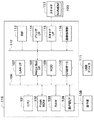
図1は、本発明の実施の形態に係る画像読み取り装置のハードウェア構成を示すブロック図である。
[First Embodiment]
<Hardware configuration>
FIG. 1 is a block diagram showing a hardware configuration of an image reading apparatus according to an embodiment of the present invention.
画像読み取り装置は、原稿読み取り手段の一例であるスキャナ117とコントローラ118より構成される。コントローラユニット118は、スキャナ117と接続することで、画像データやデバイス情報の入力を行う。CPU101は、画像読み取り装置全体を制御するプロセッサである。RAM103は、CPU101がプログラムを実行する際のワークエリアとして機能する。また、RAM103は、CPU101が画像データを処理する場合における一時記憶領域としても用いられる。 FlashROM102は書き換え可能な不揮発性メモリであり、システムを制御するための各種制御プログラムが記録される。操作部I/F104は、操作部105とのインターフェース部で、操作部105に表示する画像データを出力する。また、操作部105からユーザが入力した情報を、CPU101に伝える役割をする。USBポート110は、USBデバイス111との接続を可能にする。
The image reading apparatus includes a
以上のデバイスがシステムバス106上に配置されている。
The above devices are arranged on the
イメージバスI/F108は、システムバス106と画像データを高速で転送する画像バス112とを接続し、データ構造を変換するバスブリッジである。画像バス112は、PCIバスまたはIEEE1394で構成される。画像バス112上には以下のデバイスが配置される。
The image bus I / F 108 is a bus bridge that connects the
ラスタイメージプロセッサRIP113はPDLコードのようなベクトルデータをビットマップイメージに展開する。スキャナI/F115は、スキャナ117とコントローラユニット118を接続し、画像データの変換を行う。画像処理部116は、入力画像データに対し補正、加工、編集を行ったり、スキャナ入力画像データに対して、スキャナの補正、解像度変換等を行う。また、これに加えて、画像データの回転や、多値画像データに対してはJPEG、2値画像データはJBIG、MMR、MH等の圧縮伸張処理を行う。スキャナ117は、原稿を読み込み画像データに変換する部分である。その方式はレーザー等があるが、どの方式でも構わない。プリンタインターフェース(プリンタI/F)114は、不図示のプリンタエンジンと接続する。
The raster image processor RIP 113 expands vector data such as a PDL code into a bitmap image. A scanner I / F 115 connects the
操作部105は、LCD表示部を有し、LCD上にタッチパネルシートが貼られている。また操作キーを有している。システムの操作画面を表示するとともに、表示してあるキーが押されるとその位置情報をCPU101に伝える。
The
LANインターフェース107は、LANに接続するための機能ユニットで、LANを介してパーソナルコンピュータやサーバに画像ファイルを送信したり、他のデバイスの情報を取得したりするために使用される。
A
スキャナ117は不揮発性のメモリであるNVMEM100を備えている。スキャナ117が読み取った原稿に基づく画像データは一旦NVMEM100に格納され、その後スキャナI/F115を介してRAM103へ転送される。
The
画像読み取り装置は、スキャナ117で原稿画像を読み取って生成した画像データをHDD109へ格納したり、プリンタI/F114を介して不図示のプリンタを用いて印刷することが可能である。また、画像読み取り装置は、スキャナ117で原稿画像を読み取って生成した画像データをLAN I/F107を介して接続する不図示のコンピュータ装置へ送信することもできる。また画像読み取り装置は、スキャナ117で原稿画像を読み取って生成した画像データをUSBポート110を介して接続するUSBデバイス111(例えば、USBメモリなど)へ出力することもできる。
The image reading apparatus can store image data generated by reading an original image with the
<ファイルフォーマット>
図2は、複数ページの静止画像を同一のファイルとして記録するためのフォーマットの構成例を示す図である。
<File format>
FIG. 2 is a diagram illustrating a configuration example of a format for recording a plurality of pages of still images as the same file.
ファイルヘッダ200は、1ページ目のページヘッダ202のアドレス、対象ファイルのファイルサイズ、及び当該ファイルが複数の静止画像を同一のファイルとして記録するフォーマットである情報が記されている。
The
1ページヘッダ202は、1ページデータ203について記されたヘッダ情報である。2ページヘッダ206と2ページデータ207、3ページヘッダ210と3ページデータ211も同様の関係にある。各ページデータには静止画画像の情報が記されている。
The 1-
本フォーマットに対応していないデバイスが本フォーマットのファイルを参照した場合、1ページヘッダ202、1ページデータ203のみ参照することができる。
When a device that does not support this format refers to a file in this format, only the 1-
<ページヘッダ>
図3は、図2におけるページヘッダ202,206,210の構成例を示す図である。
<Page header>
FIG. 3 is a diagram illustrating a configuration example of the
先頭画像フラグ300はそのページが先頭画像か否かを示す領域である。ここで、先頭画像とはファイルに含まれる複数の画像の中で代表となる画像を指す。本フォーマットにおいて先頭画像は各ファイルに1つだけ必ず含まれる。
The
主画像フラグ301とはそのページに従属する従画像をもつか否かを示す領域であり、従画像フラグ302とはそのページが従属する主画像をもつか否かを示す領域である。次ページのアドレス303はそのページの次ページのページヘッダアドレスが格納される。
The
最終ページである場合には最終ページであることを示す値としてNULLが格納される。従属画像のアドレス304はそのページが主画像である場合にのみ持つ項目であり、そのページに従属する従画像のページヘッダのアドレスがそれぞれ格納される。
If it is the last page, NULL is stored as a value indicating the last page. The
カラーモード305はそのページがカラー画像であるかモノクロ画像であるかを示し、解像度306はそのページの解像度を示す。また、レイアウト307は自画像データと従属画像のレイアウト情報を示し、このレイアウト情報は画像再生時に並べて表示すべきか、また、その並べ方を示す。
A
<ページ画像分割処理>
次に、第1の実施の形態に係るページ画像分割処理について、図4及び図5を参照して説明する。
<Page image division processing>
Next, page image division processing according to the first embodiment will be described with reference to FIGS.
図4は、本実施形態に係る、スキャンしたページ画像の分割処理を示すフローチャートである。また、図5は、図4の分割処理を実行した場合のデータフローチャートである。 FIG. 4 is a flowchart showing the division processing of the scanned page image according to the present embodiment. FIG. 5 is a data flowchart when the dividing process of FIG. 4 is executed.
RAM103は、CPU101が実行する様々な処理のために用いられるので、RAM103内(ワークメモリ内)に画像データの一時記憶領域として確保できる容量は動的に変化する。従って、スキャナ117から送られる画像データのサイズ(原稿のサイズや解像度や階調数などによって変化する)によっては1ページの画像データ全てをRAM103に格納できないこともある。1ページの画像データ全てをRAM103に格納できない場合においても画像データを分割することによって原稿画像に基づく画像データのファイルを生成するための処理を説明する。
Since the
まずステップS400において、CPU101は、スキャン指示と、スキャンにより生成される画像ファイルの格納場所とが指示されたか否かを判定する。即ち、ユーザは、例えばA3原稿をスキャナ117に載せ、該操作部105を用いて、スキャン指示と、スキャンにより生成される画像ファイルの格納場所とを指示し、CPU101は、この指示動作を受け付ける。この際、画像ファイルの格納場所は、HDD109、USBデバイス111に接続された記憶媒体やデジタルカメラ、LAN I/F107に接続されたPC、或いは画像読み取り装置の記憶部などの記憶媒体であればよい。
First, in step S400, the
次にステップS401において、CPU101はスキャナ117に原稿の読み込みを指示する。スキャナ117は読み込んだ1ページ分の画像データをスキャナ117内のNVMEM100に一時格納する(図5のT1:「スキャン」)。なお、NVMEM100はスキャナ117が原稿をスキャンして生成する1ページ分の画像データを記憶することが可能な容量を有しているものとする。
In step S401, the
続いて、CPU101は、ステップS402において、一時記憶されたNVMEM100内の画像データサイズを取得し、この画像データサイズと、画像処理を行うために必要なRAM103の領域サイズに相当するワークメモリのサイズとを比較する。ここで、画像データサイズがワークメモリのサイズよりも大きければ、ステップS403へ移る。画像データサイズがワークメモリのサイズよりも小さければ、ステップS405へ移る。
Subsequently, in step S402, the
次にステップS403において、CPU101は、読み取った原稿が2ページ目以降で、分割情報画既に生成されているか否かを判定する。読み込んだ画像データが2ページ目以降であり、後述するステップS411で指示された分割情報が存在するかどうか確認し、存在する場合、ステップS404へ移る。存在しない場合、ステップS411へ移る。この場合、以前に(1ページ目の原稿読み取り時に)生成した分割情報を2ページ目以降にも用いることになる。
Next, in step S403, the
続いて、ステップS404において、CPU101は、後述するステップS412の分割情報を取得し、これに基づく分割サイズで画像データを分割するようスキャナ117へ指示する。当該指示に応答してスキャナ117から分割された画像データが転送され、CPU101は転送された画像データを一旦RAM103へ格納し、その後、HDD109に非圧縮データで保存する。このとき、本画像サイズにおける、各分割画像の座標位置を分割情報として生成してメモリに保持しておく(図5のT2:「画像分割、保存」)。
Subsequently, in step S404, the
次にステップS405において、CPU101は、非圧縮データで保持されている画像データをNVMEM100に展開し、外部で扱うことが可能な一般フォーマットJPEG等に変換する。このとき、前記ステップS404で画像データを分割しているため、分割したサイズだけのメモリ量であればよく、一度のフォーマット変換に必要なメモリ量を抑えることが可能になる(図5のT3:「フォーマット変換」)。
In step S405, the
次にステップS406において、CPU101は、前記ステップS404で取得した分割情報をレイアウト情報として分割ページファイルのヘッダに記載し、HDD109に保存する(図5のT4:「ヘッダ生成」)。続いて、ステップS407において、CPU101は、前記ステップS406でHDD109に保存した分割ページファイルを出力ファイルに追加(付与)する(図 5のT5:「ファイル結合、保存」)。
Next, in step S406, the
次にステップS408において、CPU101は、前記ステップS401でスキャンした画像を全て分割ページファイルとして保存した場合はステップS409へ移る。全て保存していない場合は、ステップS404に戻り、次の未保存分割画像をスキャナ117から取得して、同様のステップを処理する。
Next, in step S408, if the
次にステップS409において、CPU101は、前記ステップS401において、スキャナ117にまだ読み込んでいない原稿がある場合は、ステップS413へ移る。これは、ドキュメントフィーダなどを使用し複数原稿を読み込む場合などである。全ての原稿を読み込んだ場合は、ステップS410へ移る。続いてステップS410において、前記ステップS400において、指示されたファイル格納場所へ、本フローによって生成したファイルを送信し、格納する。これにより画像ファイル生成が完了する。
Next, in step S409, if there is a document that has not yet been read by the
一方、前記ステップS403において、分割情報がまだ存在しない場合には、CPU101は、ステップS411の処理を行う。ステップS411では、前記ステップS401でスキャンした画像を操作部105で表示し、ユーザによって、分割方法を指示する。指示方法は原稿がNupプリントされたものであれば、1ページに何ページプリントされた原稿かを指定する。また、この指定は、表示された画像の領域を選択することにより行う。なお、分割情報はRAM103などに記憶され。スキャンする原稿が複数枚の原稿である場合には、今回のスキャン指示によって読み取る全ての原稿に対しても同様に分割情報が適用されるものとする。
On the other hand, if there is no division information yet in step S403, the
また、この時点でユーザの指示を仰がずに、分割法方を指定する情報を予め画像読み取り装置の設定情報としてFlash ROM102、或いはHDD109に格納しておくことにより、自動的に分割情報を生成するようにしても良い。
At this time, the division information is automatically generated by storing the information for specifying the division method in advance in the
次にステップS412において、CPU101は、操作部105から、前記ステップS411でユーザが指示した分割情報を取得し、決定する。この分割情報とは、複数の矩形情報から成る。この際、送信先が、文書管理を行うシステムや画像処理を行うシステムであれば、分割後のサイズも一般的な用紙サイズに丸めこむ。これにより、文字切れが少なくなるため、分割画像データをレイアウト情報に基づき再生しなくても、OCR、画像認識等の処理にかけることが可能となる。
Next, in step S412, the
続いてステップS413において、CPU101は、処理したページが先頭ページかどうかを判断する。先頭ページの場合はステップS414へ移る。そうでない場合、前記ステップS401へ移る。
Subsequently, in step S413, the
次にステップS414において、CPU101は、先頭ページを分割した画像に対してそれぞれサイズの縮小処理を行う。縮小するサイズはサムネイル表示に適したサイズである(図5のT6:「縮小」)。
Next, in step S414, the
続いてステップS415において、CPU101は、前記ステップS414で縮小したそれぞれの分割画像を結合し1つの画像に変換する(図5のT7:「サムネイル生成」)。そしてステップS416において、前記ステップS414で作成したサムネイル画像を出力ファイルの主画像として保存する。その後、前記ステップS401へ戻る。
Subsequently, in step S415, the
<第1の実施の形態に係る利点>
本実施形態によれば、画像処理を行うワークメモリのサイズを判断することにより、読み取った画像データを分割し、送信することが可能となる。再生時には、必要に応じてレイアウト情報を参照し、分割画像を再結合することが可能となる(図5のT8:「再生」)。さらに、定型サイズに分割することにより、送信後の処理において、分割画像を再結合しなくても、処理することが可能となる。これにより、読み取った画像データのサイズが大きくても、RAM103の容量を増やすことなく、該画像データの画像処理を行うことが可能になるため、コストの軽減につながる。
<Advantages of First Embodiment>
According to the present embodiment, it is possible to divide and transmit the read image data by determining the size of the work memory that performs image processing. At the time of reproduction, it is possible to refer to the layout information as necessary and recombine the divided images (T8 in FIG. 5: “Reproduction”). Furthermore, by dividing the image into fixed sizes, it is possible to perform the processing after the transmission without recombining the divided images. As a result, even if the size of the read image data is large, image processing of the image data can be performed without increasing the capacity of the
また、作成したファイルを表示する表示装置が、本出力ファイルのフォーマットに対応していなくても、サムネイル画像により概要を表示することが可能となる。 In addition, even if the display device that displays the created file does not support the format of the output file, it is possible to display an outline using thumbnail images.
また、フォーマットに対応した表示装置においても、サムネイル表示を行う際に、分割画像を結合しなくても、主画像を表示することによってサムネイルを表示することが可能となる。 Further, even in a display device that supports the format, it is possible to display a thumbnail by displaying a main image without combining divided images when displaying thumbnails.
[第2の実施の形態]
次に、本発明の第2の実施の形態について説明する。
[Second Embodiment]
Next, a second embodiment of the present invention will be described.
第2の実施の形態が上記第1の実施の形態と異なる点は、ドキュメントフィーダにより複数原稿をスキャンしてその各原稿サイズが異なる場合に、必要な原稿のみ適切に分割することを可能にしたことである。画像読み取り装置の構成は、第1の実施形態で説明したものと同じであるものとする。 The second embodiment is different from the first embodiment in that a plurality of originals are scanned by a document feeder, and when each original size is different, only necessary originals can be appropriately divided. That is. The configuration of the image reading apparatus is the same as that described in the first embodiment.
<ページ画像原稿混載処理>
以下、第2の実施の形態に係るページ画像分割処理について、図6及び図7を参照して説明する。
<Page image original mixed processing>
Hereinafter, page image division processing according to the second embodiment will be described with reference to FIGS. 6 and 7.
図6は、本実施形態に係る、スキャンしたページ画像の分割処理を示すフローチャートである。また、図7は、図6の分割処理を実行した場合のデータフローチャートである。 FIG. 6 is a flowchart showing the division processing of the scanned page image according to the present embodiment. FIG. 7 is a data flowchart when the division process of FIG. 6 is executed.
ステップS500からステップS505までの処理は、第1の実施の形態における図4のステップS400からステップS405までの処理とそれぞれ同じである。但し、本実施の形態では、ステップS501のスキャン時には、図7のT11に示すように、ドキュメントフィーダにより複数原稿、例えばA3原稿とA4原稿をスキャンするものとする。そのうち、分割の対象となる原稿画像は、図7のT12に示すようにA3原稿の画像だけということになる。したがって、ステップS505のフォーマット変換処理は、図7のT13に示すように3枚のA4画像に対して行われることになる。 The processing from step S500 to step S505 is the same as the processing from step S400 to step S405 in FIG. 4 in the first embodiment. However, in the present embodiment, at the time of scanning in step S501, as shown at T11 in FIG. 7, a plurality of originals, for example, A3 original and A4 original are scanned by the document feeder. Among them, the document image to be divided is only the image of the A3 document as shown at T12 in FIG. Therefore, the format conversion process in step S505 is performed on the three A4 images as indicated by T13 in FIG.
次のステップS506においては、CPU101は、前記ステップS500で指示された格納場所情報(或いは画像ファイルの出力先情報)を取得する。格納場所、あるいは出力先によって、分割したページを再生時に復元するレイアウト情報が必要であるか、そうでないかを判断する。例えば、A4サイズで分割したデータを、最大用紙サイズがA4のプリンタに送信する場合、分割前のレイアウト情報があっても復元することができないため、レイアウト情報は必要ない。この場合、ステップS516へ移る。格納場所で分割データを復元する必要がある場合は、ヘッダを生成する処理(図7のT14)であるステップS507へ移る。レイアウト情報画必要であるか否かは、現在実行している原稿画像読み取りの処理に対してユーザから設定された処理内容に基づいて判断する。
In the next step S506, the
ファイルを結合し保存する処理(図7のT15)であるステップS507から、ステップS511までの処理では、第1の実施の形態における図4のステップS406からステップS410までの処理とそれぞれ同じである。 The processing from step S507 to step S511, which is processing for combining and saving files (T15 in FIG. 7), is the same as the processing from step S406 to step S410 in FIG. 4 in the first embodiment.
ステップS512では、送信先は分割が必要であるか否かを判断する。即ち、前記ステップS502においてワークメモリのサイズを超えないサイズの画像データであると判断されても、送信先の種類によっては当該画像データを分割する必要がある。例えば、送信先の画像形成装置のワークメモリのサイズが少ない場合やプリント用紙サイズが小さい場合などである。送信先が分割画像データを必要とする場合、ステップS503へ移り、分割処理を行う。送信先が分割画像データを必要としない場合は、分割せずに、ステップS515へ移る。 In step S512, it is determined whether the transmission destination needs to be divided. That is, even if it is determined in step S502 that the image data has a size that does not exceed the size of the work memory, it is necessary to divide the image data depending on the type of transmission destination. For example, when the work memory size of the destination image forming apparatus is small or the print paper size is small. When the transmission destination requires the divided image data, the process proceeds to step S503 and the dividing process is performed. If the transmission destination does not require the divided image data, the process proceeds to step S515 without dividing.
その後のステップS513及びステップS514の処理は、第1の実施の形態における図4のステップS411及びステップS412の処理とそれぞれ同じである。 The subsequent processing of step S513 and step S514 is the same as the processing of step S411 and step S412 of FIG. 4 in the first embodiment.
続くステップS515では、CPU101は、非圧縮データで保持されている画像データをNVMEM100に展開し、外部で扱うことが可能な一般フォーマットJPEG等に変換する。そして次のステップS516において、前記ステップS506で生成された画像データを単独の画像ファイルとして保存する。
In the subsequent step S515, the
その後のステップS517からステップS520までの処理は、第1の実施の形態における図4のステップS413からステップS416の処理とそれぞれ同じである。 The subsequent processing from step S517 to step S520 is the same as the processing from step S413 to step S416 in FIG. 4 in the first embodiment.
<第2の実施の形態に係る利点>
第2の実施形態によれば、原稿サイズが混載した原稿をスキャンした場合においても、分割が必要な原稿のみ分割することが可能となり、処理を効率化することが可能となる。
<Advantages of Second Embodiment>
According to the second embodiment, even when a document with a mixed document size is scanned, it is possible to divide only a document that needs to be divided, and to improve processing efficiency.
なお、本発明の目的は、以下の処理を実行することによっても達成される。即ち、上述した実施形態の機能を実現するソフトウェアのプログラムコードを記録した記憶媒体を、システム或いは装置に供給し、そのシステム或いは装置のコンピュータ(またはCPUやMPU等)が記憶媒体に格納されたプログラムコードを読み出す処理である。 The object of the present invention can also be achieved by executing the following processing. That is, a storage medium that records a program code of software that realizes the functions of the above-described embodiments is supplied to a system or apparatus, and a computer (or CPU, MPU, etc.) of the system or apparatus is stored in the storage medium. This is the process of reading the code.
この場合、記憶媒体から読み出されたプログラムコード自体が前述した実施の形態の機能を実現することになり、そのプログラムコード及び該プログラムコードを記憶した記憶媒体は本発明を構成することになる。 In this case, the program code itself read from the storage medium realizes the functions of the above-described embodiments, and the program code and the storage medium storing the program code constitute the present invention.
また、プログラムコードを供給するための記憶媒体としては、次のものを用いることができる。例えば、フロッピー(登録商標)ディスク、ハードディスク、光磁気ディスク、CD−ROM、CD−R、CD−RW、DVD−ROM、DVD−RAM、DVD−RW、DVD+RW、磁気テープ、不揮発性のメモリカード、ROM等である。または、プログラムコードをネットワークを介してダウンロードしてもよい。 Moreover, the following can be used as a storage medium for supplying the program code. For example, floppy (registered trademark) disk, hard disk, magneto-optical disk, CD-ROM, CD-R, CD-RW, DVD-ROM, DVD-RAM, DVD-RW, DVD + RW, magnetic tape, nonvolatile memory card, ROM or the like. Alternatively, the program code may be downloaded via a network.
また、コンピュータが読み出したプログラムコードを実行することにより、上記実施の形態の機能が実現される場合も本発明に含まれる。加えて、そのプログラムコードの指示に基づき、コンピュータ上で稼動しているOS(オペレーティングシステム)等が実際の処理の一部または全部を行い、その処理によって前述した実施形態の機能が実現される場合も含まれる。 Further, the present invention includes a case where the function of the above-described embodiment is realized by executing the program code read by the computer. In addition, an OS (operating system) running on the computer performs part or all of the actual processing based on an instruction of the program code, and the functions of the above-described embodiments are realized by the processing. Is also included.
更に、前述した実施形態の機能が以下の処理によって実現される場合も本発明に含まれる。即ち、記憶媒体から読み出されたプログラムコードが、コンピュータに挿入された機能拡張ボードやコンピュータに接続された機能拡張ユニットに備わるメモリに書き込まれる。その後、そのプログラムコードの指示に基づき、その機能拡張ボードや機能拡張ユニットに備わるCPU等が実際の処理の一部または全部を行う場合である。 Furthermore, a case where the functions of the above-described embodiment are realized by the following processing is also included in the present invention. That is, the program code read from the storage medium is written in a memory provided in a function expansion board inserted into the computer or a function expansion unit connected to the computer. Thereafter, based on the instruction of the program code, the CPU or the like provided in the function expansion board or function expansion unit performs part or all of the actual processing.
100 NVMEM
101 CPU
102 FlashROM
103 RAM
105 操作部
116 画像処理部
117 スキャナ
118 コントローラユニット
100 NVMEM
101 CPU
102 FlashROM
103 RAM
105
Claims (7)
前記読み取られた画像データのサイズが前記ワークメモリ内で前記画像データを格納するための領域のサイズよりも大きい場合に、該画像データを分割する分割手段と、
前記分割手段により分割された複数の分割画像データのうちの1つを前記ワークメモリに格納し、前記ワークメモリに格納された分割画像データを所定のフォーマットに変換する処理を、前記分割された複数の分割画像データの各々に対して行う変換手段と、
前記変換手段により前記所定のフォーマットに変換された複数の分割画像データから1つの画像ファイルを生成する画像ファイル生成手段と、
前記所定のフォーマットに変換された複数の分割画像データの各々に対して、レイアウト情報を含んだヘッダ情報を付与する付与手段と、
を有することを特徴とする画像読み取り装置。 A work memory for storing image data generated by the image reading means reading the document;
Dividing means for dividing the image data when the size of the read image data is larger than the size of the area for storing the image data in the work memory;
A plurality of said one of a plurality of divided image data divided by the dividing means and stored in the work memory, the process of converting the divided image data stored in the work memory in a predetermined format, which is the divided Conversion means for each of the divided image data ,
And image file generating means for generating a single image file from the plurality of divided image data converted to the predetermined format by the conversion means,
A granting unit for giving header information including layout information to each of the plurality of divided image data converted into the predetermined format;
An image reading apparatus comprising:
前記レイアウト情報には、前記分割手段により前記分割サイズで分割された複数の分割画像データを再結合するための情報が含まれることを特徴とする請求項1に記載の画像読み取り装置。 The dividing means divides the image data by the image reading means is generated by the division size when dividing the image data generated based on the original partition size specified from the outside or the image reading unit, it is previously read ,
The image reading apparatus according to claim 1, wherein the layout information includes information for recombining a plurality of divided image data divided by the division size with the division size .
画像読み取り手段が原稿を読み取って生成した画像データのサイズがワークメモリ内で前記画像データを格納するための領域のサイズよりも大きい場合に、該画像データを分割する分割工程と、
前記分割工程で分割された複数の分割画像データのうちの1つを前記ワークメモリに格納し、前記ワークメモリに格納された分割画像データを所定のフォーマットに変換する処理を、前記分割された複数の分割画像データの各々に対して行う変換工程と、
前記変換工程で前記所定のフォーマットに変換された複数の分割画像データから1つの画像ファイルを生成する画像ファイル生成工程と、
前記所定のフォーマットに変換された複数の分割画像データの各々に対して、レイアウト情報を含んだヘッダ情報を付与する付与工程と、
を有することを特徴とする画像読み取り装置の制御方法。 A method for controlling an image reading apparatus for reading an image, comprising:
A dividing step of dividing the image data when the size of the image data generated by reading the document by the image reading unit is larger than the size of the area for storing the image data in the work memory;
A plurality of said one of a plurality of divided image data divided by the dividing step and stored in the work memory, the process of converting the divided image data stored in the work memory in a predetermined format, which is the divided A conversion step performed on each of the divided image data of
An image file generation step of generating one image file from the plurality of divided image data converted into the predetermined format in the conversion step;
An assigning step of giving header information including layout information to each of the plurality of divided image data converted into the predetermined format;
A control method for an image reading apparatus, comprising:
画像読み取り手段が原稿を読み取って生成した画像データのサイズがワークメモリ内で前記画像データを格納するための領域のサイズよりも大きい場合に、該画像データを分割する分割ステップと、
前記分割ステップで分割された複数の分割画像データのうちの1つを前記ワークメモリに格納し、前記ワークメモリに格納された分割画像データを所定のフォーマットに変換する処理を、前記分割された複数の分割画像データの各々に対して行う変換ステップと、
前記変換ステップで前記所定のフォーマットに変換された複数の分割画像データから1つの画像ファイルを生成する画像ファイル生成ステップと、
前記所定のフォーマットに変換された複数の分割画像データの各々に対して、レイアウト情報を含んだヘッダ情報を付与する付与ステップと、
を有することを特徴とするプログラム。 A computer-readable program for executing a control method of an image reading apparatus for reading an image,
A division step of dividing the image data when the size of the image data generated by reading the document by the image reading unit is larger than the size of the area for storing the image data in the work memory;
A plurality of said one of a plurality of divided image data divided by the dividing step and stored in the work memory, the process of converting the divided image data stored in the work memory in a predetermined format, which is the divided A conversion step performed on each of the divided image data ;
An image file generation step of generating one image file from the plurality of divided image data converted into the predetermined format in the conversion step;
A granting step of giving header information including layout information to each of the plurality of divided image data converted into the predetermined format;
The program characterized by having.
Priority Applications (2)
| Application Number | Priority Date | Filing Date | Title |
|---|---|---|---|
| JP2008327910A JP5178497B2 (en) | 2008-12-24 | 2008-12-24 | Image reading apparatus, image reading apparatus control method, and program |
| US12/644,788 US8358445B2 (en) | 2008-12-24 | 2009-12-22 | Image reading apparatus, control method therefor, and storage medium |
Applications Claiming Priority (1)
| Application Number | Priority Date | Filing Date | Title |
|---|---|---|---|
| JP2008327910A JP5178497B2 (en) | 2008-12-24 | 2008-12-24 | Image reading apparatus, image reading apparatus control method, and program |
Publications (3)
| Publication Number | Publication Date |
|---|---|
| JP2010154040A JP2010154040A (en) | 2010-07-08 |
| JP2010154040A5 JP2010154040A5 (en) | 2012-02-16 |
| JP5178497B2 true JP5178497B2 (en) | 2013-04-10 |
Family
ID=42265631
Family Applications (1)
| Application Number | Title | Priority Date | Filing Date |
|---|---|---|---|
| JP2008327910A Expired - Fee Related JP5178497B2 (en) | 2008-12-24 | 2008-12-24 | Image reading apparatus, image reading apparatus control method, and program |
Country Status (2)
| Country | Link |
|---|---|
| US (1) | US8358445B2 (en) |
| JP (1) | JP5178497B2 (en) |
Families Citing this family (2)
| Publication number | Priority date | Publication date | Assignee | Title |
|---|---|---|---|---|
| JP2017175404A (en) * | 2016-03-24 | 2017-09-28 | コニカミノルタ株式会社 | Image formation apparatus and program |
| CN114398001B (en) * | 2021-12-03 | 2024-02-20 | 北京数字电视国家工程实验室有限公司 | Super-large sequence image transmission method, device and computer |
Family Cites Families (12)
| Publication number | Priority date | Publication date | Assignee | Title |
|---|---|---|---|---|
| JP3015134B2 (en) * | 1991-04-23 | 2000-03-06 | キヤノン株式会社 | Image processing method and apparatus |
| JPH07288705A (en) * | 1994-04-18 | 1995-10-31 | Canon Inc | Device and method for processing color image |
| JP3581477B2 (en) * | 1996-03-04 | 2004-10-27 | 株式会社リコー | Digital copier |
| WO1997042758A1 (en) * | 1996-05-09 | 1997-11-13 | Matsushita Electric Industrial Co., Ltd. | Multimedia optical disk, reproducing device, and reproducing method capable of superposing sub-video upon main video in well-balanced state irrespective of position of main video on screen |
| JP2003060831A (en) * | 2001-06-07 | 2003-02-28 | Canon Inc | Image input control method, information processing apparatus, storage medium, and program |
| JP2003244446A (en) * | 2002-02-21 | 2003-08-29 | Canon Inc | Image processor and image processing method |
| JP2004254101A (en) | 2003-02-20 | 2004-09-09 | Ricoh Co Ltd | Image processing apparatus, image processing method, program, and recording medium |
| US7526144B2 (en) * | 2003-02-20 | 2009-04-28 | Ricoh Company, Ltd. | Image processing method, image expansion method, image output method, image conversion method, image processing apparatus, image expansion apparatus, image output apparatus, image conversion apparatus, and computer-readable storage medium |
| JP4895340B2 (en) * | 2005-03-31 | 2012-03-14 | キヤノン株式会社 | Information processing apparatus and method |
| JP4455459B2 (en) * | 2005-09-02 | 2010-04-21 | キヤノン株式会社 | Printing system, printing apparatus, and printing method |
| JP4827705B2 (en) * | 2005-12-15 | 2011-11-30 | キヤノン株式会社 | Image processing apparatus and image processing method |
| JP2008271418A (en) * | 2007-04-24 | 2008-11-06 | Canon Inc | Image forming unit |
-
2008
- 2008-12-24 JP JP2008327910A patent/JP5178497B2/en not_active Expired - Fee Related
-
2009
- 2009-12-22 US US12/644,788 patent/US8358445B2/en not_active Expired - Fee Related
Also Published As
| Publication number | Publication date |
|---|---|
| US8358445B2 (en) | 2013-01-22 |
| JP2010154040A (en) | 2010-07-08 |
| US20100157382A1 (en) | 2010-06-24 |
Similar Documents
| Publication | Publication Date | Title |
|---|---|---|
| JP3970102B2 (en) | Image processing apparatus, image processing method, and program | |
| JPH1083263A (en) | Image forming device and method for image processing | |
| US8891091B2 (en) | Image processing apparatus, image processing control method and computer-readable storage medium | |
| JP2006262078A (en) | Image processor | |
| JP2008112385A (en) | Image processor, control method for image processor, and control program | |
| JP5173278B2 (en) | Image processing apparatus, image processing method, and computer program | |
| JP5178497B2 (en) | Image reading apparatus, image reading apparatus control method, and program | |
| US20080232683A1 (en) | Image processing apparatus, image processing method and computer program product | |
| JP7172150B2 (en) | Information processing device, communication system, image forming method, program | |
| US8724161B2 (en) | Method, apparatus, and computer program product for processing image data of plural images to combine for output to a recording medium | |
| JP2006155308A (en) | Image forming apparatus | |
| JP4815311B2 (en) | Image processing apparatus and image processing method | |
| US8547586B2 (en) | Scanner device utilizing an internal storage unit and an external storage unit corresponding to header information | |
| JP2001199135A (en) | Apparatus and method for controlling printing and memory medium | |
| JP4968927B2 (en) | Image processing apparatus, image processing method, and program | |
| JP5264553B2 (en) | Image processing apparatus, control method therefor, and program | |
| JP2006285792A (en) | Image processor and image processing method | |
| JP4065550B2 (en) | Image input / output control device, image processing device, image processing method in image input / output control device, and image processing method in image processing device | |
| JP4697933B2 (en) | Image processing apparatus, image input / output apparatus and methods thereof | |
| JP2006211553A (en) | Image processing apparatus and method thereof | |
| US20110128298A1 (en) | Display system, image processing apparatus, control method therefor, and storage medium | |
| JP5062311B2 (en) | Image processing device | |
| JP5202265B2 (en) | Image processing apparatus, program, and control method for image processing apparatus | |
| JP2011040892A (en) | Image processing apparatus and method for the same | |
| JP2008048434A (en) | Image processor |
Legal Events
| Date | Code | Title | Description |
|---|---|---|---|
| A521 | Request for written amendment filed |
Free format text: JAPANESE INTERMEDIATE CODE: A523 Effective date: 20111222 |
|
| A621 | Written request for application examination |
Free format text: JAPANESE INTERMEDIATE CODE: A621 Effective date: 20111222 |
|
| A977 | Report on retrieval |
Free format text: JAPANESE INTERMEDIATE CODE: A971007 Effective date: 20120627 |
|
| A131 | Notification of reasons for refusal |
Free format text: JAPANESE INTERMEDIATE CODE: A131 Effective date: 20120717 |
|
| A521 | Request for written amendment filed |
Free format text: JAPANESE INTERMEDIATE CODE: A523 Effective date: 20120918 |
|
| TRDD | Decision of grant or rejection written | ||
| A01 | Written decision to grant a patent or to grant a registration (utility model) |
Free format text: JAPANESE INTERMEDIATE CODE: A01 Effective date: 20121211 |
|
| A61 | First payment of annual fees (during grant procedure) |
Free format text: JAPANESE INTERMEDIATE CODE: A61 Effective date: 20130108 |
|
| R151 | Written notification of patent or utility model registration |
Ref document number: 5178497 Country of ref document: JP Free format text: JAPANESE INTERMEDIATE CODE: R151 |
|
| FPAY | Renewal fee payment (event date is renewal date of database) |
Free format text: PAYMENT UNTIL: 20160118 Year of fee payment: 3 |
|
| LAPS | Cancellation because of no payment of annual fees |