JP5175264B2 - Apparatus and method for modifying tissue - Google Patents

Apparatus and method for modifying tissue Download PDF

Info

Publication number
JP5175264B2
JP5175264B2 JP2009500564A JP2009500564A JP5175264B2 JP 5175264 B2 JP5175264 B2 JP 5175264B2 JP 2009500564 A JP2009500564 A JP 2009500564A JP 2009500564 A JP2009500564 A JP 2009500564A JP 5175264 B2 JP5175264 B2 JP 5175264B2
Authority
JP
Japan
Prior art keywords
tissue
patient
distal
proximal
target
Prior art date
Legal status (The legal status is an assumption and is not a legal conclusion. Google has not performed a legal analysis and makes no representation as to the accuracy of the status listed.)
Expired - Fee Related
Application number
JP2009500564A
Other languages
Japanese (ja)
Other versions
JP2009529981A (en
JP2009529981A5 (en
Inventor
ブレイチ,ジェフリー,エル.
サアーダット,バヒド
スピサック,スティーブン,エイ.
アシュレイ,ジョン
レギドレギド,ロイ
ブリーム,ジェフリー
レギドレギド,ロナルド
ドリューズ,マイク
フヴァルカ,エドウィン,ジェイ.
Current Assignee (The listed assignees may be inaccurate. Google has not performed a legal analysis and makes no representation or warranty as to the accuracy of the list.)
Baxano Inc
Original Assignee
Baxano Inc
Priority date (The priority date is an assumption and is not a legal conclusion. Google has not performed a legal analysis and makes no representation as to the accuracy of the date listed.)
Filing date
Publication date
Priority claimed from US11/375,265 external-priority patent/US7887538B2/en
Priority claimed from US11/405,848 external-priority patent/US8430881B2/en
Priority claimed from US11/405,859 external-priority patent/US20070213734A1/en
Priority claimed from US11/406,486 external-priority patent/US7938830B2/en
Priority claimed from US11/429,377 external-priority patent/US8048080B2/en
Application filed by Baxano Inc filed Critical Baxano Inc
Publication of JP2009529981A publication Critical patent/JP2009529981A/en
Publication of JP2009529981A5 publication Critical patent/JP2009529981A5/ja
Application granted granted Critical
Publication of JP5175264B2 publication Critical patent/JP5175264B2/en
Expired - Fee Related legal-status Critical Current
Anticipated expiration legal-status Critical

Links

Images

Classifications

    • AHUMAN NECESSITIES
    • A61MEDICAL OR VETERINARY SCIENCE; HYGIENE
    • A61BDIAGNOSIS; SURGERY; IDENTIFICATION
    • A61B17/00Surgical instruments, devices or methods, e.g. tourniquets
    • A61B17/16Bone cutting, breaking or removal means other than saws, e.g. Osteoclasts; Drills or chisels for bones; Trepans
    • A61B17/1659Surgical rasps, files, planes, or scrapers
    • AHUMAN NECESSITIES
    • A61MEDICAL OR VETERINARY SCIENCE; HYGIENE
    • A61BDIAGNOSIS; SURGERY; IDENTIFICATION
    • A61B17/00Surgical instruments, devices or methods, e.g. tourniquets
    • A61B17/00234Surgical instruments, devices or methods, e.g. tourniquets for minimally invasive surgery
    • AHUMAN NECESSITIES
    • A61MEDICAL OR VETERINARY SCIENCE; HYGIENE
    • A61BDIAGNOSIS; SURGERY; IDENTIFICATION
    • A61B17/00Surgical instruments, devices or methods, e.g. tourniquets
    • A61B17/02Surgical instruments, devices or methods, e.g. tourniquets for holding wounds open; Tractors
    • AHUMAN NECESSITIES
    • A61MEDICAL OR VETERINARY SCIENCE; HYGIENE
    • A61BDIAGNOSIS; SURGERY; IDENTIFICATION
    • A61B17/00Surgical instruments, devices or methods, e.g. tourniquets
    • A61B17/16Bone cutting, breaking or removal means other than saws, e.g. Osteoclasts; Drills or chisels for bones; Trepans
    • A61B17/1613Component parts
    • A61B17/1626Control means; Display units
    • AHUMAN NECESSITIES
    • A61MEDICAL OR VETERINARY SCIENCE; HYGIENE
    • A61BDIAGNOSIS; SURGERY; IDENTIFICATION
    • A61B17/00Surgical instruments, devices or methods, e.g. tourniquets
    • A61B17/16Bone cutting, breaking or removal means other than saws, e.g. Osteoclasts; Drills or chisels for bones; Trepans
    • A61B17/1662Bone cutting, breaking or removal means other than saws, e.g. Osteoclasts; Drills or chisels for bones; Trepans for particular parts of the body
    • A61B17/1671Bone cutting, breaking or removal means other than saws, e.g. Osteoclasts; Drills or chisels for bones; Trepans for particular parts of the body for the spine
    • AHUMAN NECESSITIES
    • A61MEDICAL OR VETERINARY SCIENCE; HYGIENE
    • A61BDIAGNOSIS; SURGERY; IDENTIFICATION
    • A61B17/00Surgical instruments, devices or methods, e.g. tourniquets
    • A61B17/16Bone cutting, breaking or removal means other than saws, e.g. Osteoclasts; Drills or chisels for bones; Trepans
    • A61B17/17Guides or aligning means for drills, mills, pins or wires
    • A61B17/1739Guides or aligning means for drills, mills, pins or wires specially adapted for particular parts of the body
    • A61B17/1757Guides or aligning means for drills, mills, pins or wires specially adapted for particular parts of the body for the spine
    • AHUMAN NECESSITIES
    • A61MEDICAL OR VETERINARY SCIENCE; HYGIENE
    • A61BDIAGNOSIS; SURGERY; IDENTIFICATION
    • A61B17/00Surgical instruments, devices or methods, e.g. tourniquets
    • A61B17/34Trocars; Puncturing needles
    • A61B17/3417Details of tips or shafts, e.g. grooves, expandable, bendable; Multiple coaxial sliding cannulas, e.g. for dilating
    • A61B17/3421Cannulas
    • AHUMAN NECESSITIES
    • A61MEDICAL OR VETERINARY SCIENCE; HYGIENE
    • A61BDIAGNOSIS; SURGERY; IDENTIFICATION
    • A61B17/00Surgical instruments, devices or methods, e.g. tourniquets
    • A61B17/56Surgical instruments or methods for treatment of bones or joints; Devices specially adapted therefor
    • A61B17/58Surgical instruments or methods for treatment of bones or joints; Devices specially adapted therefor for osteosynthesis, e.g. bone plates, screws, setting implements or the like
    • A61B17/88Osteosynthesis instruments; Methods or means for implanting or extracting internal or external fixation devices
    • A61B17/8861Apparatus for manipulating flexible wires or straps
    • AHUMAN NECESSITIES
    • A61MEDICAL OR VETERINARY SCIENCE; HYGIENE
    • A61BDIAGNOSIS; SURGERY; IDENTIFICATION
    • A61B17/00Surgical instruments, devices or methods, e.g. tourniquets
    • A61B17/02Surgical instruments, devices or methods, e.g. tourniquets for holding wounds open; Tractors
    • A61B17/0218Surgical instruments, devices or methods, e.g. tourniquets for holding wounds open; Tractors for minimally invasive surgery
    • AHUMAN NECESSITIES
    • A61MEDICAL OR VETERINARY SCIENCE; HYGIENE
    • A61BDIAGNOSIS; SURGERY; IDENTIFICATION
    • A61B17/00Surgical instruments, devices or methods, e.g. tourniquets
    • A61B17/32Surgical cutting instruments
    • A61B17/320016Endoscopic cutting instruments, e.g. arthroscopes, resectoscopes
    • A61B17/32002Endoscopic cutting instruments, e.g. arthroscopes, resectoscopes with continuously rotating, oscillating or reciprocating cutting instruments
    • AHUMAN NECESSITIES
    • A61MEDICAL OR VETERINARY SCIENCE; HYGIENE
    • A61BDIAGNOSIS; SURGERY; IDENTIFICATION
    • A61B17/00Surgical instruments, devices or methods, e.g. tourniquets
    • A61B17/56Surgical instruments or methods for treatment of bones or joints; Devices specially adapted therefor
    • A61B17/58Surgical instruments or methods for treatment of bones or joints; Devices specially adapted therefor for osteosynthesis, e.g. bone plates, screws, setting implements or the like
    • A61B17/88Osteosynthesis instruments; Methods or means for implanting or extracting internal or external fixation devices
    • A61B17/8897Guide wires or guide pins
    • AHUMAN NECESSITIES
    • A61MEDICAL OR VETERINARY SCIENCE; HYGIENE
    • A61BDIAGNOSIS; SURGERY; IDENTIFICATION
    • A61B17/00Surgical instruments, devices or methods, e.g. tourniquets
    • A61B17/00234Surgical instruments, devices or methods, e.g. tourniquets for minimally invasive surgery
    • A61B2017/00238Type of minimally invasive operation
    • A61B2017/00261Discectomy
    • AHUMAN NECESSITIES
    • A61MEDICAL OR VETERINARY SCIENCE; HYGIENE
    • A61BDIAGNOSIS; SURGERY; IDENTIFICATION
    • A61B17/00Surgical instruments, devices or methods, e.g. tourniquets
    • A61B2017/00831Material properties
    • A61B2017/00867Material properties shape memory effect
    • AHUMAN NECESSITIES
    • A61MEDICAL OR VETERINARY SCIENCE; HYGIENE
    • A61BDIAGNOSIS; SURGERY; IDENTIFICATION
    • A61B17/00Surgical instruments, devices or methods, e.g. tourniquets
    • A61B17/32Surgical cutting instruments
    • A61B2017/32006Surgical cutting instruments with a cutting strip, band or chain, e.g. like a chainsaw
    • AHUMAN NECESSITIES
    • A61MEDICAL OR VETERINARY SCIENCE; HYGIENE
    • A61BDIAGNOSIS; SURGERY; IDENTIFICATION
    • A61B17/00Surgical instruments, devices or methods, e.g. tourniquets
    • A61B17/34Trocars; Puncturing needles
    • A61B2017/348Means for supporting the trocar against the body or retaining the trocar inside the body
    • A61B2017/3482Means for supporting the trocar against the body or retaining the trocar inside the body inside
    • A61B2017/3484Anchoring means, e.g. spreading-out umbrella-like structure
    • A61B2017/3488Fixation to inner organ or inner body tissue
    • AHUMAN NECESSITIES
    • A61MEDICAL OR VETERINARY SCIENCE; HYGIENE
    • A61BDIAGNOSIS; SURGERY; IDENTIFICATION
    • A61B90/00Instruments, implements or accessories specially adapted for surgery or diagnosis and not covered by any of the groups A61B1/00 - A61B50/00, e.g. for luxation treatment or for protecting wound edges
    • A61B90/08Accessories or related features not otherwise provided for
    • A61B2090/0801Prevention of accidental cutting or pricking
    • A61B2090/08021Prevention of accidental cutting or pricking of the patient or his organs

Description

関連出願の相互参照
本出願は、2006年3月13日に出願した「Methods and Apparatus for Tissue Modification」という名称の米国暫定出願第11/375、265号(代理人整理番号026445−000700US)、2006年4月17日に出願した「Mechanical Tissue Modification Devices and Methods」という名称の米国暫定出願第11/405、848号(代理人整理番号026445−000720US)、2006年4月17日に出願した「Powered Tissue Modification Devices and Methods」という名称の米国暫定出願第11/406、486号(代理人整理番号026445−000721US)、2006年4月17日に出願した「Tissue Modification Barrier Devices and Methods」という名称の米国暫定出願第11/405、859号(代理人整理番号026445−000722)、2006年5月4日に出願した「Flexible Tissue Rasp」という名称の米国暫定出願第11/429、377号(代理人整理番号026445−000723US)の優先権を主張する。前述の総ての参照の開示は、参照によりここに組み込まれている。
CROSS REFERENCE TO RELATED APPLICATIONS This application is a US Provisional Application No. 11 / 375,265 entitled “Methods and Apparatus for Tissue Modification” filed March 13, 2006 (Attorney Docket No. 026445-000700US), 2006. US Provisional Application No. 11 / 405,848 (Attorney Docket No. 026445-000720US) entitled “Mechanical Tissue Modification Devices and Methods” filed on April 17, 2006, “Powered” filed on April 17, 2006 US Provisional Application No. 11 / 406,486 (Attorney Docket No. 026445-000721US) entitled "Tissue Modification Devices and Methods", United States of America entitled "Tissue Modification Barrier Devices and Methods" filed April 17, 2006 Provisional Application No. 11/405, 859 (Attorney Docket No. 026445-00 0722), and claims priority to US Provisional Application No. 11 / 429,377 (Attorney Docket No. 026445-000723US) entitled “Flexible Tissue Rasp” filed on May 4, 2006. The disclosures of all the aforementioned references are incorporated herein by reference.

本発明は、患者の組織を修正する方法及び装置に関する。   The present invention relates to a method and apparatus for modifying a patient's tissue.

身体の多くの病的状態は、身体組織の増大、移動、置換、及び/又は様々な他の変化により引き起こされ、身体組織が1以上の他の正常な組織又は臓器を圧迫(又は「影響を与える」)。例えば、癌性の腫瘍は隣接する臓器を圧迫し、その臓器の機能及び/又は健康状態に悪影響を与える。他の事例では、骨増殖(又は「骨棘」)、骨及び/若しくは軟組織の関節炎の変化、余分な軟組織、又は他の異常肥大の骨若しくは軟組織の状態が、近くの神経及び/又は血管組織に影響を及ぼし、1以上の神経の機能を傷つけ、血管の血流を減少させ、又はこれら双方を生じさせる。増殖又は移動して隣接する組織を圧迫する組織の他の事例には、靭帯、腱、嚢胞、軟骨、瘢痕組織、血管、脂肪組織、腫瘍、血腫、及び炎症組織が含まれる。   Many pathological states of the body are caused by body tissue growth, movement, replacement, and / or various other changes that cause body tissue to compress (or “impact” one or more other normal tissues or organs). give"). For example, a cancerous tumor compresses adjacent organs and adversely affects the function and / or health of the organ. In other cases, bone growth (or “osteophytes”), changes in bone and / or soft tissue arthritis, excess soft tissue, or other abnormally hypertrophic bone or soft tissue conditions may be present in nearby nerve and / or vascular tissue. Affecting one or more nerve functions, reducing vascular blood flow, or both. Other examples of tissue that proliferates or moves and compresses adjacent tissue include ligaments, tendons, cysts, cartilage, scar tissue, blood vessels, adipose tissue, tumors, hematomas, and inflammatory tissue.

組織の侵食により生じる状態の一の特定の例は、脊髄の狭窄である。脊髄の狭窄は、脊髄内の神経組織及び/又は血管組織が、これを圧迫する1以上の構造により侵食されるときに生じ(「神経及び/又は神経血管の侵食」)、1以上の症状を引き起こす。組織の侵食は、脊髄中心管(脊髄及び馬尾が内側を通る垂直な通路)、脊髄の側窩、又は1以上の椎間孔(脊髄から分岐する神経根が通過する開口)などの脊髄内のいくつかの異なる領域で生じる。   One particular example of a condition caused by tissue erosion is spinal stenosis. Spinal stenosis occurs when nerve tissue and / or vascular tissue in the spinal cord is eroded by one or more structures that compress it ("nervous and / or neurovascular erosion"). cause. Tissue erosion can occur in the spinal cord, such as the central spinal canal (vertical passage through which the spinal cord and tail are passed), the lateral fovea of the spinal cord, or one or more intervertebral foramen (openings through which nerve roots branch off the spinal cord) It occurs in several different areas.

説明の目的で、図1は、断面図で示された馬尾(脊髄の基部から脊髄中心間を通って延在する馬の尾の形状をした神経の束)を有する椎骨(脊柱の骨の一つ)と、脊髄中心管から出て椎骨の両側の椎間孔内を延在する2つの神経根の概略的な平面図を示している(図1は、正確なスケールで描かれておらず、例示目的のみを意図するものである。ここでは、本出願に添付した図面は、解剖学的な正確性を意図するものではなく、説明を容易にする例示的な目的であることを強調すべきである。)。脊髄管及び馬尾は、脊髄に沿って脊髄中心管内を垂直に走っており、一方、神経根は神経管から分岐し、隣接する椎骨管の馬尾は、椎間孔内を延在している。   For illustration purposes, FIG. 1 shows a vertebra (one of the spine bones) with a horsetail (a bundle of nerves shaped like a horse's tail extending from the base of the spinal cord through the center of the spinal cord) shown in cross-section. And a schematic plan view of two nerve roots that exit the central spinal canal and extend through the intervertebral foramen on both sides of the vertebra (Figure 1 is not drawn to scale) It is intended for illustrative purposes only, and it is emphasized here that the drawings attached to this application are not intended for anatomical accuracy, but are exemplary purposes for ease of explanation. Should.) The spinal canal and horsetail run vertically in the central spinal canal along the spinal cord, while the nerve root diverges from the neural tube and the caudad of the adjacent vertebral canal extends through the intervertebral foramen.

脊髄の狭窄の共通の原因は、図1に示すように、黄色靭帯(椎骨に取り付けられ連結された靭帯の一つ)の座屈及び肥厚である。黄色靭帯の座屈及び肥厚は、1以上の神経血管構造、後根神経節、神経根、及び/又は脊髄自体に影響を与える。脊椎内の神経及び神経血管の圧縮の別の共通の原因は、1以上の椎間板(隣接する椎骨間の柔軟な椎間板)の病気であり、これは、椎間板の崩壊、突出、又はヘルニアを引き起こす。図1では、椎間板が、3つの矢印により示されており、椎間板が脊髄中心管内に突出し、あるいはヘルニアの状態になり、脊髄、馬尾及び/又は個部の神経根に突き当たる様子が明示されている。脊柱内の神経及び神経血管の衝突の他の原因には、1以上の面関節の肥大(脊椎関節突起としても知られており、面関節は、隣接する椎骨間の関節を提供し、2つの椎骨の上関節窩の突起が図1に示されている)、椎骨上の骨増殖体の形成(骨増殖又は「骨棘」)、脊椎すべり症(隣接する椎骨に対する1の椎骨の滑動)、及び(面関節)滑液嚢胞が含まれる。椎間板、骨、靭帯又は他の組織は、脊髄、馬尾、分岐する脊髄神経及び/又は脊髄内の血管に影響を与え、機能の低下、虚血(血液の供給不足)、及び神経又は神経血管組織の恒久的な損傷さえ引き起こす。患者にとっては、これは、痛み、正常でない感覚、及び/又は強さ又は移動の喪失として現われる。   A common cause of spinal stenosis is buckling and thickening of the yellow ligament (one of the ligaments attached and connected to the vertebra), as shown in FIG. The buckling and thickening of the ligamentum flavum affects one or more neurovascular structures, dorsal root ganglia, nerve roots, and / or the spinal cord itself. Another common cause of nerve and neurovascular compression in the spine is one or more intervertebral disc (soft discs between adjacent vertebrae), which cause disc disruption, protrusion, or hernia. In FIG. 1, the intervertebral disc is indicated by three arrows, clearly showing that the intervertebral disc protrudes into the central spinal canal or becomes hernia and strikes the spinal cord, the tail and / or individual nerve roots. . Other causes of nerve and neurovascular collisions in the spinal column include enlargement of one or more facet joints (also known as spinal joint processes, which provide joints between adjacent vertebrae, Vertebral upper glenoid processes are shown in FIG. 1), formation of bone growth on the vertebrae (bone growth or “bone spine”), spondylolisthesis (sliding of one vertebra with respect to an adjacent vertebra), And (face joint) synovial cysts. Intervertebral discs, bones, ligaments or other tissues affect the spinal cord, cauda equina, branching spinal nerves and / or blood vessels in the spinal cord, reduced function, ischemia (insufficient blood supply), and neural or neurovascular tissue Cause even permanent damage. For the patient, this manifests itself as pain, abnormal sensations, and / or loss of strength or movement.

米国では、脊髄の狭窄は50歳以上の大人の4%から6%に発生し、これは、60歳以上の患者にとって前述の腰部の手術の最もよくある理由である。脊髄の狭窄の症状の治療に対する従来の取り組みには、全身の薬物治療及び物理的な治療が含まれている。また、硬膜外ステロイド注射も利用されるが、リングの持続性のある利益(ling lasting benefit)を提供しない。これらの取り組みが不適切な場合、脊髄の狭窄の現在の治療は、脊椎の靭帯、軟骨、骨棘、滑液嚢胞、軟骨、及び骨を除去して、神経及び神経血管組織用の空間を増やす外科手術に限定される。脊髄の狭窄の治療の標準的な治療には、後に黄色靱帯の除去(「切除」)が行われる椎弓切除術(1以上の椎骨の板の完全な除去(図1を参照))又は椎弓切開術(板の部分的な除去)が含まれる。さらに、手術には、部分的又は時折完全な脊椎関節突起切除術(椎骨間の1以上の面関節の全部又は一部の除去)が含まれる。湾曲した椎間板は、神経の衝突の原因となり、椎間板の要素が、椎間板切除手術で外科的に取り除かれる。   In the United States, spinal stenosis occurs in 4% to 6% of adults over the age of 50, which is the most common reason for the aforementioned lumbar surgery for patients over the age of 60. Traditional approaches to the treatment of spinal stenosis symptoms include systemic drug treatment and physical treatment. Epidural steroid injections are also used, but do not provide a ling lasting benefit. When these approaches are inadequate, current treatment of spinal stenosis removes spinal ligaments, cartilage, osteophytes, synovial cysts, cartilage, and bone to increase space for nerve and neurovascular tissue Limited to surgery. Standard treatments for the treatment of spinal stenosis include laminectomy (complete removal of one or more vertebral plates (see FIG. 1)) followed by removal of the ligamentum flavum ("resection") or vertebrae Archectomy (partial removal of the board) is included. In addition, surgery includes partial or occasional complete spine arthrotomy (removal of all or part of one or more facet joints between vertebrae). Curved discs cause nerve collisions and disc components are surgically removed during discectomy.

椎弓切除術及び脊椎関節突起切除術により生じる椎骨の除去は、非常に不適切な脊椎の生成された領域を残し、患者の椎骨にさらに損傷を与え、かつ患者の動作能力を制限する極めて侵襲的なさらなる固定処置を必要とする。脊椎固定術では、いくつかの種類のサポート機構が椎骨に取り付けられ、椎骨が相互に移動するのを阻止し、隣接する椎骨を固定するのを可能にする。残念なことに、外科的な脊椎固定は、背骨の固定された部分の動作能力を低下させ、患者の動作範囲を減少させ、隣接する椎骨部分の椎間板や面関節を圧迫する。   The removal of the vertebrae caused by laminectomy and spine arthrotomy leaves a highly inappropriate spine-generated area, further damage to the patient's vertebrae, and limit the patient's ability to operate Additional fixation procedures are required. In spinal fusion, several types of support mechanisms are attached to the vertebrae to prevent the vertebrae from moving relative to each other and allow adjacent vertebrae to be fixed. Unfortunately, surgical spinal fixation reduces the ability of the fixed part of the spine to move, reduces the patient's range of motion, and compresses the intervertebral discs and facet joints of adjacent vertebral parts.

椎弓切除、脊椎関節突起切除、椎間板切除、及び脊柱の固定はしばしば、短時間で神経及び神経血管の衝突の症状を改善する一方、これらの処置は、非常に侵襲的であり、脊柱の機能を低下させ、通常の解剖学的構造を大幅に崩壊させ、前述したような治療をしていない患者に見られる程度の長期の病的状態を増やす。   While laminectomy, spinectomy, discectomy, and spinal fixation often improve symptoms of nerve and neurovascular collisions in a short time, these procedures are very invasive and spinal function , Significantly disrupting normal anatomy, and increasing the long-term morbidity seen in patients not treated as described above.

したがって、椎骨内の神経及び神経血管の衝突を解決する侵襲的でない方法及び装置が所望されている。理想的には、椎骨内の神経及び神経血管の衝突を解決する方法及び装置は、1以上のターゲット組織を利用するとともに、隣接する又は近くの非ターゲット組織に対する不必要な影響を阻止する。また、理想的には、このような方法及び装置は、わずかに侵襲的であり、かなりの量の椎骨、関節、又は他の脊椎指示構造を除去することなく衝突を減らし、これにより脊柱を固定する必要がなく、理想的には現在利用されている外科処置により生じる長期の病状の程度を減らす。非ターゲット組織を修正することなく、椎骨ではなく身体の一部のターゲット組織を修正する非侵襲的な方法及び装置が有利である。これらの目的の少なくとも一部が、本発明により達成される。   Accordingly, a non-invasive method and apparatus that resolves nerve and neurovascular collisions within the vertebra is desired. Ideally, the method and apparatus for resolving nerve and neurovascular collisions in the vertebrae utilizes one or more target tissues and prevents unwanted effects on adjacent or nearby non-target tissues. Also, ideally, such methods and devices are slightly invasive and reduce collisions without removing significant amounts of vertebrae, joints, or other spinal pointing structures, thereby fixing the spinal column And ideally reduces the extent of long-term conditions caused by currently available surgical procedures. A non-invasive method and apparatus that modifies the target tissue of a part of the body rather than the vertebra without modifying the non-target tissue is advantageous. At least some of these objectives will be met by the present invention.

背景技術。スレッドワイヤ(threadwire)(Tソー)及びGigliソーなどの可撓性のあるワイヤソー、チェインソーが、身体の骨や他の組織を切断するために1800年代後半から使用されている。例えば、Brunori A等の"Celebrationg the Centenial(1984-1994):Leonardo Gigli and His Wire Saw," J Neurosurg 82:1086-1090, 1995を参照。このような鋸の一例が、1876年11月28日にP.A. Stohlmannに付与された米国特許第8250に記されている。Tソーを用いて椎骨を切断することの説明は、カワハラN等の"Recapping T-Saw Laminoplasty for Spinal Cord Tumors," SPINE Volume 24, Number 12, pp. 1363-1370にある。   Background technology. Flexible wire saws, such as threadwire (T saw) and Gigli saws, chain saws have been used since the late 1800s to cut bones and other tissues of the body. See, for example, Brunori A et al. "Celebration g the Centenial (1984-1994): Leonardo Gigli and His Wire Saw," J Neurosurg 82: 1086-1090, 1995. An example of such a saw is described in US Pat. No. 8,250, issued Nov. 28, 1876 to P.A. Stohlmann. An explanation of cutting vertebrae using a T-saw is found in Kawara N et al. “Recapping T-Saw Laminoplasty for Spinal Cord Tumors,” SPINE Volume 24, Number 12, pp. 1363-1370.

脊髄の狭窄を治療する方法及び装置は、例えば、米国特許出願第2006/0264994及び2004/0122459、国際特許出願WO01/08571に記されている。膝の腔から軟骨を除去する手術器具が、米国特許第3,835,859に記されている。   Methods and devices for treating spinal stenosis are described, for example, in US Patent Applications 2006/0264994 and 2004/0122459, International Patent Application WO 01/08571. A surgical instrument for removing cartilage from the knee cavity is described in US Pat. No. 3,835,859.

様々な実施例において、本発明は、患者の組織を修正する方法、装置及びシステムを提供する。一般に、この方法、装置及びシステムは、1以上のターゲット組織を修正する1以上の組織修正部材を具える細長くて少なくとも可撓性のある組織修正装置を必要とする。組織修正装置は、組織修正部材(又は複数の組織修正部材)がターゲット組織を修正する位置にあるときに、非ターゲット組織への損傷を阻止あるいは防ぐように構成された組織修正装置の1以上の側部、表面又は部分が、非ターゲット組織に接触するように構成してもよい。様々な実施例では、組織を修正する処理の間、固定力及び/又は張力が、患者の内側又は外側の組織修正装置の遠位部又は近位部に又はその近くにかかる。また、引っ張り又は張力も装置の反対側の端部に加わり、組織修正部材をターゲット組織に押しつける。次に、組織修正部材が作動して組織を修正する一方、ターゲット組織を超えて近位又は遠位方向に有意に伸張しない。いくつかの実施例では、組織修正部材は、修正されるターゲット組織の長さとほぼ同じ組織修正装置の長さに沿って配置される。   In various embodiments, the present invention provides methods, apparatus and systems for modifying patient tissue. In general, the method, apparatus, and system require an elongated, at least flexible tissue modification device that includes one or more tissue modification members that modify one or more target tissues. The tissue modification device includes one or more tissue modification devices configured to prevent or prevent damage to non-target tissue when the tissue modification member (or tissue modification members) are in a position to modify the target tissue. Sides, surfaces or portions may be configured to contact non-target tissue. In various embodiments, during the process of modifying tissue, the fixation force and / or tension is applied to or near the distal or proximal portion of the tissue modification device inside or outside the patient. Also, tension or tension is applied to the opposite end of the device, pressing the tissue modifying member against the target tissue. The tissue modifying member then operates to modify the tissue while not significantly extending proximally or distally beyond the target tissue. In some embodiments, the tissue modifying member is positioned along the length of the tissue modifying device that is approximately the same as the length of the target tissue to be modified.

「固定力を加えること」により、装置の一部又は装置全体が実質的に安定又は動作が自由になるように力が加わることを意味する。したがって、固定力を加えることは、装置の総ての動作を阻止することに限定されず、実際には、いくつかの実施例では、固定力が加わる装置は1以上の方向に移動する。他の実施例では、固定力は、装置の一部を実質的に安定させるために加えられる一方、装置の他の部分は、より自由に動くことができる。以下にさらに詳細に説明するように、一実施例において固定力を加えることは、装置の端部或いはその近くを把持する装置のユーザを必要とする。他の実施例では、装置は、1以上の固定部材を用いて固定力を加えてもよい。多くの実施例では、固定力は、患者の身体の1以上の組織により、またはこれに対して加えられ、組織はしばしば、力を加える(あるいは補助する)ように動く。このように、再び固定力を装置に加えることは、必ずしも装置の総ての動作が取り除かれることを意味するものではない。もちろん、いくつかの実施例では、装置(又は装置の一部)の総ての動作又はほぼ総ての動作を取り除くことが可能であり、それが所望されており、いくつかの実施例では、固定力がそれを行うために用いられる。   By “applying a fixing force” is meant that a force is applied such that a portion of the device or the entire device is substantially stable or free to operate. Thus, applying a fixing force is not limited to preventing all operation of the device, and in fact, in some embodiments, the device applying the fixing force moves in one or more directions. In other embodiments, the securing force is applied to substantially stabilize a portion of the device, while other portions of the device can move more freely. As will be described in more detail below, applying a fixing force in one embodiment requires a user of the device to grip the end of the device or near it. In other embodiments, the device may apply a securing force using one or more securing members. In many embodiments, the fixation force is applied by or against one or more tissues of the patient's body, and the tissue often moves to apply (or assist) the force. Thus, applying a fixing force to the device again does not necessarily mean that all movements of the device are removed. Of course, in some embodiments it is possible and desirable to remove all or nearly all movement of the device (or part of the device), and in some embodiments, A fixing force is used to do that.

本発明の態様の方法、装置、及びシステムは通常、組織を修正する一方、周囲の組織に対する好ましくない修正又は損傷を阻止する。固定力を一の端部又はこれに近くに加え、かつ張力を反対の端部に又はこれの近くに加えることにより組織修正装置に張力を加えることは、装置の組織修正部材を強化し、制限された治療範囲で効果的に機能する。非常に可撓性のある装置に張力を加えることにより、装置の外形を相対的に小さくすることができ、これにより、非侵襲的な処置や、ターゲット組織に対して代替的な解決手段が有利である他の処置で装置の使用を容易にする。   The methods, devices, and systems of aspects of the present invention typically modify tissue while preventing undesirable modification or damage to surrounding tissue. Applying tension to the tissue modification device by applying a fixation force at or near one end and applying tension at or near the opposite end strengthens and limits the tissue modification member of the device. Function effectively within the therapeutic range. By applying tension to a very flexible device, the device profile can be made relatively small, which is advantageous for non-invasive procedures and alternative solutions for the target tissue. Facilitates the use of the device in other treatments.

本出願では、「組織を修正する」又は「組織修正」の語は、組織の切断、除去、剥がす、縮小、燃焼、溶解、冷却、加熱、凍結、投薬、磨く、ステントの挿入、又は移動などの好適な修正を含むが、これらに限定されない。いくつかの実施例では、記載されている方法、装置及びシステムは、神経の衝突、神経血管の衝突、及び/又は脊髄の狭窄の治療等のために、脊柱内の組織を修正するのに用いられる。代替的な実施例では、身体の他の部分のターゲット組織を修正してもよい。   In this application, the terms “modify tissue” or “tissue modification” refer to tissue cutting, removal, peeling, shrinking, burning, melting, cooling, heating, freezing, dispensing, polishing, stent insertion, or movement, etc. Including, but not limited to, suitable modifications. In some embodiments, the described methods, devices and systems are used to modify tissue in the spinal column, such as for the treatment of nerve collisions, neurovascular collisions, and / or spinal stenosis. It is done. In alternative embodiments, target tissue in other parts of the body may be modified.

本発明の一の態様では、患者の1以上の組織を修正する装置が、近位部と遠位部を有する少なくとも部分的に可撓性のある細長の本体と、治療されるターゲット組織の長さとほぼ同じ限定された長さとなるように前記本体の一方の側に沿って配置された組織修正部材と、非ターゲット組織に対向するように前記組織修正部材の近くに配置される非外傷性表面と、前記組織修正部材に連結され、前記本体の近位部に延在し、前記細長の本体を近位方向又は遠位方向に有意に移動させることなく前記組織修正部材を作動させる作動部と、前記組織修正部材を前記ターゲット組織に対して移動させるために、前記細長の本体の近位部及び遠位部に又はこれらの近くに張力又は固定力のうち少なくとも一方を容易に加える手段とを具える。いくつかの実施例では、前記細長の本体の可撓性のある部分は、前記装置の近位部及び遠位部が患者の体外に延在するともに、患者の脊柱の椎間孔を介して延在するように構成されており、また、前記組織修正部材は、脊髄の狭窄を治療又は緩和するために軟らかい組織又は骨の少なくとも一方を除去するように構成してもよい。   In one aspect of the invention, an apparatus for modifying one or more tissues of a patient includes an at least partially flexible elongated body having a proximal portion and a distal portion, and a length of target tissue to be treated. A tissue modifying member disposed along one side of the body to have a limited length substantially the same as the atraumatic surface disposed near the tissue modifying member to face a non-target tissue. And an actuating portion coupled to the tissue modifying member, extending to a proximal portion of the body, and actuating the tissue modifying member without significantly moving the elongated body proximally or distally. Means for easily applying at least one of tension or fixation force at or near the proximal and distal portions of the elongated body to move the tissue modifying member relative to the target tissue; Have. In some embodiments, the flexible portion of the elongate body may extend through the intervertebral space of the patient's spinal column while the proximal and distal portions of the device extend outside the patient's body. The tissue modifying member may be configured to extend and may be configured to remove at least one of soft tissue or bone to treat or alleviate spinal stenosis.

いくつかの実施例では、前記細長の本体が、その長さに沿って任意の位置で5mm以下の幅を有する。いくつかの実施例では、前記細長の本体が、ガイドワイヤコネクタ、ガイドワイヤルーメン、レール、トラック、又は縦方向のくぼみ(impression)であって、これに沿って前記装置が送達装置上を通過し、又は送達装置の後ろ側で引っ張られる縦方向のくぼみのうち少なくとも一つを具えてもよい。いくつかの実施例では、前記組織修正部材が、3cm以下の長さの前記本体の長さに沿って配置されてもよい。   In some embodiments, the elongate body has a width of 5 mm or less at any location along its length. In some embodiments, the elongate body is a guide wire connector, guide wire lumen, rail, track, or longitudinal impression along which the device passes over the delivery device. Or at least one of the longitudinal recesses pulled behind the delivery device. In some embodiments, the tissue modifying member may be disposed along the length of the body that is 3 cm or less in length.

前記装置に組み込まれる組織修正部材の例には、ロンジュール、キューレット、メス、1以上の切断ブレード、ハサミ、鉗子、プローブ、鬼目やすり、やすり、研磨部材、1以上の小さな面、電気外科手術装置、双極電極、単極電極、熱電極、回転式電力機構シェーバ、往復式電力機構シェーバ、電力機構ばり(burr)、レーザ、超音波水晶、低温プローブ、及び加圧されるウォータジェットが含まれるが、これらに限定されない。一実施例では、前記組織修正部材が、2つの対向するブレードを具えてもよく、これらのうちの少なくとも一方が移動してブレードが一体になり、ターゲット組織を切断する。いくつかの実施例では、前記組織修正部材が、前記細長の本体上の開口から外側へ配置可能でもよい。   Examples of tissue modifying members incorporated into the device include Ronjoules, Curettes, scalpels, one or more cutting blades, scissors, forceps, probes, demon files, files, abrasive members, one or more small surfaces, electrosurgery Includes surgical device, bipolar electrode, monopolar electrode, thermal electrode, rotary power mechanism shaver, reciprocating power mechanism shaver, power mechanism burr, laser, ultrasonic crystal, cryogenic probe, and pressurized water jet However, it is not limited to these. In one embodiment, the tissue modifying member may comprise two opposing blades, at least one of which moves to unite the blades and cut the target tissue. In some embodiments, the tissue modifying member may be positionable outwardly from an opening on the elongated body.

いくつかの実施例では、前記力を加える手段が、患者の外側から力を容易に加えるように構成された近位及び遠位ハンドルを具えてもよく、前記近位又は遠位ハンドルのうち少なくとも一方が、前記細長の本体に取り外し可能に取り付けてもよい。任意で、いくつかの実施例はさらに、組織を修正する処置の間に非ターゲット組織が損傷するのを阻止すべく、前記細長の本体に取り外し可能に連結される少なくとも1の保護部材を具えてもよい。任意で、いくつかの実施例はさらに、前記細長の本体内に収容され又はこれに連結される組織収集チャンバを具えてもよい。   In some embodiments, the means for applying force may comprise proximal and distal handles configured to easily apply force from outside the patient, wherein at least one of the proximal or distal handles One may be removably attached to the elongated body. Optionally, some embodiments further comprise at least one protective member removably coupled to the elongate body to prevent damage to non-target tissue during a tissue modification procedure. Also good. Optionally, some embodiments may further comprise a tissue collection chamber housed within or coupled to the elongate body.

本発明の別の態様では、患者の脊柱内の1以上の組織を修正するシステムが、組織修正装置と、少なくとも1のガイドワイヤと、使用のための命令とを具えてもよい。前記組織修正装置は、近位部と遠位部を有する少なくとも部分的に可撓性のある細長の本体と、治療されるターゲット組織の長さとほぼ同じ限定された長さとなるように前記本体の一方の側に沿って配置される組織修正部材と、非ターゲット組織に対向するように前記組織修正部材の近くに配置される非外傷性表面と、前記組織修正部材に連結され、前記本体の近位部に延在し、前記細長の本体を近位方向又は遠位方向に有意に移動させることなく前記組織修正部材を作動させる作動部と、前記組織修正部材を前記ターゲット組織に対して移動させるために、前記細長の本体の近位部及び遠位部に又はこれらの近くに張力又は固定力のうち少なくとも一方を容易に加える手段と、を具えてもよい。   In another aspect of the invention, a system for modifying one or more tissues in a patient's spinal column may comprise a tissue modification device, at least one guide wire, and instructions for use. The tissue modification device includes an elongated body that is at least partially flexible having a proximal portion and a distal portion, and a limited length that is approximately the same as the length of the target tissue to be treated. A tissue modifying member disposed along one side, an atraumatic surface disposed near the tissue modifying member to face the non-target tissue, and connected to the tissue modifying member, near the body. An actuating portion extending to a position and actuating the tissue modifying member without significantly moving the elongated body proximally or distally; and moving the tissue modifying member relative to the target tissue To this end, it may comprise means for easily applying at least one of tension or securing force at or near the proximal and distal portions of the elongated body.

いくつかの実施例では、前記システムは、複数の組織修正装置を具えてもよい。いくつかの実施例では、前記システムは、拡張部と、導入シースとを具え、当該導入シースを介して前記組織修正装置が患者の体内に前進させてもよい。   In some embodiments, the system may comprise a plurality of tissue modification devices. In some embodiments, the system may include an extension and an introducer sheath through which the tissue modification device is advanced into the patient's body.

本発明の別の態様では、脊柱内の組織を修正する装置が、前記脊柱の硬膜上腔内でターゲット組織と非ターゲット組織の間を通過可能な大きさを有する遠位部と近位部とを有するシャフトと、前記シャフトの遠位部から延在し、固定力又は張力のうち少なくとも一方を前記シャフトに容易に加えるように構成された遠位の力を加える部材と、前記シャフトの遠位部で又はこれの近くで前記シャフトに連結された移動可能な組織修正部材と、前記組織修正部材に連結された駆動部材と、前記駆動部材に連結された動力伝達部材と、を具えてもよい。いくつかの実施例では、前記シャフトの遠位部の可撓性のある部分が、患者の脊柱の椎間孔を通って延在するとともに、前記シャフトの近位部と前記遠位の力を加える部材が患者の体外へ延在するように構成してもよい。また、いくつかの実施例では、前記組織修正部材は、脊髄の狭窄を治療又は緩和すべく、軟らかい組織又は骨のうち少なくとも一方を除去するように構成してもよい。   In another aspect of the present invention, a device for modifying tissue in the spinal column has a distal portion and a proximal portion that are sized to pass between a target tissue and a non-target tissue within the epidural space of the spinal column. A distal end of the shaft that extends from a distal portion of the shaft and is configured to easily apply at least one of a securing force or tension to the shaft; and a distal end of the shaft A movable tissue correction member connected to the shaft at or near the position, a drive member connected to the tissue correction member, and a power transmission member connected to the drive member Good. In some embodiments, a flexible portion of the distal portion of the shaft extends through an intervertebral foramen of a patient's spinal column, and the proximal portion of the shaft and the distal force are applied. You may comprise so that the member to add may extend outside a patient's body. In some embodiments, the tissue modification member may be configured to remove at least one of soft tissue or bone to treat or alleviate spinal stenosis.

いくつかの実施例はさらに、前記シャフトの前記近位部で又はこれの近くに連結され、かつ固定力又は張力のうち少なくとも一方を前記シャフトに容易に加えるように構成された近位の力を加える部材を具えてもよい。いくつかの実施例では、例えば、前記近位の力を加える部材がハンドルを具えてもよい。任意で、このような実施例はさらに、前記ハンドルに連結され、かつ前記少なくとも1の駆動部材を作動させる作動部を具えてもよい。   Some embodiments further include a proximal force coupled at or near the proximal portion of the shaft and configured to easily apply at least one of a securing force or tension to the shaft. You may provide the member to add. In some embodiments, for example, the proximal force applying member may comprise a handle. Optionally, such an embodiment may further comprise an actuating portion coupled to the handle and actuating the at least one drive member.

いくつかの実施例では、前記シャフトの遠位部が、7mm以下の幅を有してもよい。いくつかの実施例では、前記シャフトの遠位部が、2mm以下の高さを有してもよい。いくつかの実施例では、前記遠位の力を加える部材が、前記シャフトの遠位の伸長部を具えてもよい。任意で、前記遠位の力を加える部材がさらに、前記遠位の伸長部に連結可能な取り外し可能なハンドルを具えてもよい。   In some embodiments, the distal portion of the shaft may have a width of 7 mm or less. In some embodiments, the distal portion of the shaft may have a height of 2 mm or less. In some embodiments, the distal force applying member may comprise a distal extension of the shaft. Optionally, the member applying the distal force may further comprise a removable handle connectable to the distal extension.

いくつかの実施例では、前記シャフトがさらに、前記遠位部に開口を具えており、前記組織修正部材が、前記開口を介して組織を修正してもよい。任意で、いくつかの実施例は、前記シャフトの遠位部に又はこれの近くに配置され、修正される組織の視覚化を容易にする視覚化部材を具えてもよい。いくつかの実施例はさらに、限定ではなくが、洗浄液体ルーメン、吸引ルーメン、組み合わされた洗浄/吸引ルーメン、ガイドワイヤルーメン、光ファイバルーメン、1以上の視覚化装置を通すためのルーメン、前記動力伝達部材を通すためのルーメン、及び1以上の操縦部材を通すためのルーメンなどの前記シャフト内を延在する少なくとも1のルーメンを具えてもよい。   In some embodiments, the shaft may further comprise an opening in the distal portion, and the tissue modifying member may modify tissue through the opening. Optionally, some embodiments may include a visualization member disposed at or near the distal portion of the shaft to facilitate visualization of the tissue being modified. Some embodiments further include, but are not limited to, a cleaning liquid lumen, a suction lumen, a combined cleaning / aspiration lumen, a guidewire lumen, a fiber optic lumen, a lumen for passing one or more visualization devices, the power There may be at least one lumen extending through the shaft, such as a lumen for passing the transmission member and a lumen for passing one or more steering members.

様々な代替的な実施例では、前記動力伝達部材は、1以上の無線周波数、超音波、レーザ、マイクロ波、水、熱、及び低温の動力伝達部材を具えてもよい。いくつかの実施例では、前記シャフトの遠位部が、組織を修正する処置の間に非ターゲット組織に対する好ましくない損傷を阻止するために、前記組織修正部材の近くに配置された組織保護面を具えてもよい。いくつかの実施例はさらに、組織を修正する処置の間に非ターゲット組織に対する好ましくない損傷を阻止するために、前記シャフトに滑動可能に連結された少なくとも1のバリア装置を具えてもよい。さらに、いくつかの実施例は、前記組織保護面又は前記バリア装置に接触する組織を刺激すべく、前記組織保護面又は前記バリア装置に連結された少なくとも1の電極を具えてもよい。いくつかの実施例では、前記シャフトが、除去された組織を収集するために、その遠位端又はこれの近くに中空のチャンバを具えてもよい。   In various alternative embodiments, the power transmission member may comprise one or more radio frequency, ultrasonic, laser, microwave, water, heat, and cold power transmission members. In some embodiments, the distal portion of the shaft includes a tissue protective surface disposed near the tissue modification member to prevent undesirable damage to non-target tissue during a tissue modification procedure. It may be provided. Some embodiments may further comprise at least one barrier device slidably coupled to the shaft to prevent undesired damage to non-target tissue during a tissue modification procedure. Further, some embodiments may include at least one electrode coupled to the tissue protective surface or the barrier device to stimulate tissue that contacts the tissue protective surface or the barrier device. In some embodiments, the shaft may include a hollow chamber at or near its distal end to collect the removed tissue.

本発明の別の態様では、患者の体内の組織を修正する装置が、患者のターゲット組織と非ターゲット組織との間を通過可能な大きさを有する遠位部と近位部とを有する少なくとも部分的に可撓性のある細長の本体と、前記細長の本体の近位部及び遠位部に連結され、固定力及び張力のうち少なくとも一方を前記細長の本体に容易に加えるように構成された近位及び遠位の力を加える部材と、前記細長の本体と連結される移動可能な組織修正部材と、前記組織修正部材に連結された駆動部材と、当該駆動部材に連結された動力伝達部材とを具えてもよい。いくつかの実施例では、前記細長の本体の大きさにより、前記本体の可撓性のある部分が、患者の脊柱の椎間孔を介して延在可能であるともに、前記装置の近位部及び遠位部が患者から外側へ延在可能でもよい。また、いくつかの実施例では、前記組織修正部材が、脊髄の狭窄を治療又は緩和すべく、軟らかい組織又は骨の少なくとも一方を除去するように構成してもよい。   In another aspect of the invention, an apparatus for modifying tissue within a patient's body includes at least a portion having a distal portion and a proximal portion that are sized to pass between the target tissue and non-target tissue of the patient. And a flexible elongated body coupled to a proximal portion and a distal portion of the elongated body, and configured to easily apply at least one of fixing force and tension to the elongated body. A member for applying proximal and distal forces; a movable tissue modifying member coupled to the elongated body; a drive member coupled to the tissue modifying member; and a power transmission member coupled to the drive member. May be included. In some embodiments, the size of the elongate body allows the flexible portion of the body to extend through the intervertebral foramen of the patient's spinal column and the proximal portion of the device And the distal portion may extend outward from the patient. Also, in some embodiments, the tissue modifying member may be configured to remove at least one of soft tissue or bone to treat or alleviate spinal stenosis.

いくつかの実施例では、前記近位及び遠位の力を加える部材が、それぞれハンドルを具え、当該ハンドルのうち少なくとも1つが取り外し可能でもよい。いくつかの実施例はさらに、前記ハンドルの一つに連結され、前記駆動部材を作動させる作動部を具えてもよい。いくつかの実施例では、前記細長の本体の大きさにより、前記本体の少なくとも一部が、患者の脊柱の椎間孔を通過可能でもよい。   In some embodiments, the proximal and distal force applying members may each comprise a handle, and at least one of the handles may be removable. Some embodiments may further comprise an actuating portion coupled to one of the handles to actuate the drive member. In some embodiments, the size of the elongate body may allow at least a portion of the body to pass through the intervertebral foramen of the patient's spinal column.

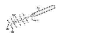
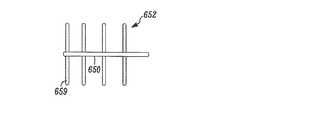
本発明の別の態様では、組織を修正する処置の間に患者の組織に対する好ましくない損傷を阻止する装置が、患者の体内への通過を容易にする収縮した状態から、非ターゲット組織の保護を強化する拡張した状態に変化可能な少なくとも1の形状が変化する部分と、前記形状が変化する部分から延在し、前記バリア装置が患者の体内を通過するのを容易にする低い外形を有し、患者の皮膚の開口からターゲット組織と非ターゲット組織の領域又はこれの近くの領域に延在するのに十分な長さを有する少なくとも1の細長部分と、前記バリアが少なくとも1のガイド部材を超えて患者の体内を通過可能にする、前記バリアの少なくとも一部に沿って延在する少なくとも1のガイド形状(feature)とを具えてもよい。一般に、前記バリア装置は、患者の皮膚上の第1の開口から前記ターゲット組織と非ターゲット組織との間を通過するのに十分な全長を有する。   In another aspect of the invention, a device that prevents undesired damage to a patient's tissue during a tissue modification procedure protects non-target tissue from a contracted state that facilitates passage into the patient's body. At least one shape-changing portion capable of changing to an expanded expanded state, and a low profile extending from the shape-changing portion to facilitate passage of the barrier device through the patient's body At least one elongate portion having a length sufficient to extend from an opening in the patient's skin to a region of target tissue and non-target tissue or in the vicinity thereof; and the barrier exceeds at least one guide member And at least one guide feature extending along at least a portion of the barrier to allow passage through the patient's body. Generally, the barrier device has a total length sufficient to pass between a target tissue and a non-target tissue from a first opening on the patient's skin.

いくつかの実施例では、前記装置が、患者の皮膚上の第1の開口から、患者の脊柱の硬膜上腔内で前記脊柱内のターゲット組織と非ターゲット組織との間を延在可能な全長、大きさ、及び構成を有してもよい。いくつかの実施例では、前記装置の全長は、前記装置が患者の体外から、前記第1の開口を通って前記ターゲット組織と非ターゲット組織との間に延在し、患者の皮膚上の第2の開口を通って患者の体外に出ることが可能なほど十分に長いことを特徴とする装置。   In some embodiments, the device can extend from a first opening on the patient's skin and between target and non-target tissue in the spinal column within the epidural space of the patient's spinal column. It may have a total length, size, and configuration. In some embodiments, the total length of the device extends from the patient's body through the first opening between the target tissue and the non-target tissue, and the total length of the device on the patient's skin. A device characterized by being long enough to be able to exit the patient through two openings.

いくつかの実施例では、前記少なくとも1の細長部分が、前記形状が変化する部分の近位端から延在する近位の細長部分と、前記形状が変化する部分の遠位端から延在する遠位の細長部分とを具えてもよい。いくつかの実施例では、前記装置はさらに、バリア送達シースを具えてもよく、当該バリア送達シースを介して、前記バリア装置が患者の体内に通される。いくつかの実施例では、前記形状が変化する部分が、前記バリア送達装置から離れるときに自動的に形状を変化させてもよい。他の実施例では、前記装置はさらに、前記形状が変化する部分に連結され、かつ当該部分を収縮した状態から拡張した状態に変化させる少なくとも1の作動部を具えてもよい。   In some embodiments, the at least one elongate portion extends from a proximal elongate portion extending from a proximal end of the shape changing portion and a distal end of the shape changing portion. A distal elongate portion. In some embodiments, the device may further comprise a barrier delivery sheath through which the barrier device is passed into the patient's body. In some embodiments, the portion that changes shape may automatically change shape as it leaves the barrier delivery device. In another embodiment, the device may further comprise at least one actuating part connected to the part that changes shape and changing the part from a contracted state to an expanded state.

いくつかの実施例では、前記少なくとも1のガイド形状が、ガイドワイヤルーメン、分離ルーメン(split lumen)、レール、トラック、及び縦方向のくぼみで構成される群から選択される。いくつかの実施例では、少なくとも1のガイド形状が、前記バリア部材に沿って1以上の組織修正装置の案内を容易にするように構成されている。いくつかの実施例はさらに、前記ターゲット組織又は非ターゲット組織のうち少なくとも一方に電流を送達すべく、前記バリア装置に連結された少なくとも1の導電性電極を具えてもよい。前記装置はさらに、前記組織に対する前記電流の影響を監視する少なくとも1の監視装置を具えてもよく、当該監視装置が、筋電図検査(EMG)監視装置及び体感覚性誘発電位(SSEP)監視装置で構成される群から選択される。   In some embodiments, the at least one guide shape is selected from the group consisting of a guidewire lumen, a split lumen, a rail, a track, and a longitudinal recess. In some embodiments, at least one guide shape is configured to facilitate guidance of one or more tissue modification devices along the barrier member. Some embodiments may further comprise at least one conductive electrode coupled to the barrier device to deliver current to at least one of the target tissue or non-target tissue. The apparatus may further comprise at least one monitoring device for monitoring the effect of the current on the tissue, the monitoring device comprising an electromyography (EMG) monitoring device and somatosensory evoked potential (SSEP) monitoring. Selected from the group consisting of devices.

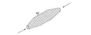
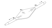
いくつかの実施例では、前記バリア装置の形状が変化する部分が、前記脊柱内で処置を行うために組織修正装置に対向する前面と、非ターゲット組織に対向する背面とを具えてもよい。いくつかの実施例では、前記形状が変化する部分は、拡張可能な骨組み(scaffold)、ヒドロゲル素材、ワイヤメッシュ、拡張可能なステント、及び膨張可能な袋で構成される群から選択してもよい。   In some embodiments, the portion of the barrier device that changes shape may comprise a front surface facing a tissue modification device for performing a procedure in the spinal column and a back surface facing a non-target tissue. In some embodiments, the shape changing portion may be selected from the group consisting of an expandable scaffold, a hydrogel material, a wire mesh, an expandable stent, and an inflatable bag. .

発明の別の態様では、脊髄の狭窄を治療又は緩和すべく、患者の脊柱内の組織を修正する装置が、近位部分と遠位部分とを有する少なくとも部分的に可撓性のある細長の本体と、当該細長の本体の一方の側の一部に沿って配置される研磨面と、前記研磨面がターゲット組織と対向するように配置された場合に、非ターゲット組織に対向するように前記研磨面の近くに配置される非研磨面と、張力を前記細長の本体に加え、かつ伝達するのを容易にすべく、前記近位部分で又はこれの近くで前記細長の本体に連結される近位の張力部材と、張力を前記細長の本体に加え、かつ伝達するのを容易にすべく、前記遠位部分で又はこれの近くで前記細長の本体に連結され、前記近位の張力部材に直接連結されない遠位の張力部材と、を具えてもよい。   In another aspect of the invention, an apparatus for modifying tissue in a patient's spinal column to treat or alleviate spinal stenosis comprises an at least partially flexible elongated body having a proximal portion and a distal portion. A main body, a polishing surface disposed along a part of one side of the elongated main body, and the polishing surface when facing the target tissue, the polishing surface is disposed so as to face the non-target tissue. A non-abrasive surface disposed near the polishing surface and coupled to the elongate body at or near the proximal portion to facilitate applying and transmitting tension to the elongate body. A proximal tension member coupled to the elongated body at or near the distal portion to facilitate applying and transmitting tension to and from the elongated body; And a distal tension member that is not directly coupled to.

一実施例では、前記細長の本体が、5mm以下の幅と、2mm以下の高さを有してもよい。いくつかの実施例では、前記細長の本体が、ガイドワイヤコネクタ、ガイドワイヤルーメン、レール、トラック、又は縦方向のくぼみ(impression)であって、これに沿って前記装置が送達装置上を通過し、又は送達装置の後ろ側で引っ張られる縦方向のくぼみを具えてもよい。いくつかの実施例では、前記近位及び遠位の張力部材がハンドルを具えてもよく、当該ハンドルのうちの少なくとも一つは、前記細長の本体に取り外し可能に取り付けてもよい。別の実施例では、前記近位及び遠位の張力部材のうちの少なくとも一つが、前記細長の本体内から配置可能でもよい。   In one embodiment, the elongated body may have a width of 5 mm or less and a height of 2 mm or less. In some embodiments, the elongate body is a guide wire connector, guide wire lumen, rail, track, or longitudinal impression along which the device passes over the delivery device. Or a longitudinal indentation that is pulled behind the delivery device. In some embodiments, the proximal and distal tension members may comprise handles, and at least one of the handles may be removably attached to the elongate body. In another embodiment, at least one of the proximal and distal tension members may be positionable from within the elongated body.

いくつかの実施例はさらに、組織を修正する処置の間に前記非ターゲット組織を損傷から守るために、前記細長の本体に連結される少なくとも1の保護部材を具えてもよい。いくつかの実施例では、前記保護部材を患者の体外で固定するために、少なくとも1の固定装置を具えてもよい。いくつかの実施例では、前記固定装置が、これらの近位部及び遠位部において又はこれの近くで前記保護部材に取り外し可能に連結される近位及び遠位の固定装置を具えてもよい。いくつかの実施例では、前記保護部材が、その長さに沿って少なくとも1の開口を具えて、当該開口を介して前記研磨面が露出してターゲット組織を修正してもよい。任意で、いくつかの実施例はさらに、前記保護部材の位置を検査するために、前記保護部材に連結される少なくとも1の電極を具えてもよい。任意で、いくつかの実施例は、前記装置を検査するために、前記研磨面及び前記非研磨面の少なくとも一方で又はこれの近くで前記組織修正装置に連結される少なくとも1の電極を具えてもよい。いくつかの実施例では、前記装置はまた、吸引及び洗浄の少なくとも一方を提供すべく、前記細長の本体内に少なくとも1のルーメンを具えてもよい。   Some embodiments may further comprise at least one protective member coupled to the elongate body to protect the non-target tissue from damage during a tissue modification procedure. In some embodiments, at least one securing device may be included to secure the protection member outside the patient's body. In some embodiments, the fixation device may comprise proximal and distal fixation devices removably coupled to the protective member at or near their proximal and distal portions. . In some embodiments, the protective member may include at least one opening along its length through which the polishing surface is exposed to modify the target tissue. Optionally, some embodiments may further comprise at least one electrode coupled to the protection member to inspect the position of the protection member. Optionally, some embodiments comprise at least one electrode coupled to the tissue modification device at or near the polishing surface and / or the non-polishing surface to inspect the device. Also good. In some embodiments, the device may also include at least one lumen within the elongate body to provide at least one of aspiration and cleaning.

本発明の別の態様では、脊髄の狭窄を治療又は緩和すべく、患者の脊柱内の組織を修正する装置が、近位部と遠位部と長さに沿った少なくとも1の開口とを有する少なくとも部分的に可撓性のある細長の保護部材と、前記保護部材内に少なくとも部分的に配置される少なくとも部分的に可撓性のある細長の組織修正部材であって、近位部と遠位部と少なくとも1の研磨面とを具える組織修正部材と、張力を第1の方向に容易に加えるために、前記保護部材及び前記組織修正部材の少なくとも一方の近位部に又はこれの近くに設けられた少なくとも1の近位の張力部材と、張力を第2の方向に容易に加えるために、前記保護部材及び前記組織修正部材の少なくとも一方の遠位部に又はこれの近くに設けられ、前記近位の張力部材に直接連結されない少なくとも1の遠位の張力部材と、を具えてもよい。   In another aspect of the invention, an apparatus for modifying tissue in a patient's spinal column to treat or alleviate spinal stenosis has a proximal portion, a distal portion, and at least one opening along the length. An elongate protective member that is at least partially flexible, and an at least partially flexible elongate tissue modifying member that is at least partially disposed within the protective member, wherein the elongate protective member is distant from the proximal portion. A tissue modifying member comprising a position and at least one abrasive surface; and at or near the proximal portion of at least one of the protective member and the tissue modifying member to easily apply tension in a first direction At least one proximal tension member provided on the distal end of the protective member and at least one distal portion of the tissue modifying member for easily applying tension in the second direction. Connected directly to the proximal tension member And tensile member of at least one distal There may comprise a.

本発明の別の態様では、患者の組織を修正する方法が、少なくとも部分的に可撓性のある細長の組織修正装置を患者の体内のターゲット組織と非ターゲット組織との間に前進させるステップと、前記組織修正部材が前記ターゲット組織に対向し、前記非ターゲット組織に対向しないように、前記組織修正装置の組織修正部材を前記ターゲット組織の近くに配置するステップと、張力を前記組織修正装置の遠位部及び近位部又はこれの近くに加えて、前記組織修正部材を前記ターゲット組織に対して移動させるステップと、組織を修正する間に、前記組織修正部材が、前記ターゲット組織を超えて前記組織修正装置の近位部又は遠位部に向かって有意に延在することを阻止しつつ、前記組織修正部材を用いて前記ターゲット組織を修正するステップと、を具えてもよい。   In another aspect of the invention, a method of modifying a patient's tissue advances an at least partially flexible elongated tissue modification device between a target tissue and a non-target tissue in the patient's body; Positioning the tissue correction member of the tissue correction device close to the target tissue so that the tissue correction member faces the target tissue and not the non-target tissue; and tension is applied to the tissue correction device. In addition to moving the tissue modifying member relative to the target tissue in addition to or near the distal and proximal portions, and during modifying the tissue, the tissue modifying member extends beyond the target tissue. A step of modifying the target tissue using the tissue modification member while preventing significant extension toward the proximal or distal portion of the tissue modification device. And up, it may comprise a.

いくつかの実施例では、前記組織修正装置を前進させるステップが、前記装置の近位部及び遠位部が患者の体外に延在するように、前記装置の可撓性のある部分を患者の脊柱の溝を介して硬膜上腔内に前進させてもよい。いくつかの実施例では、前記組織修正装置を前進させるステップが、湾曲した経路に沿って椎間孔を介して前記可撓性のある部分を前進させてもよい。いくつかの実施例では、前記ターゲット組織を修正するステップが、脊髄の狭窄を治療又は緩和すべく、軟らかい組織又は骨の少なくとも一方を除去してもよい。   In some embodiments, the step of advancing the tissue modification device causes the flexible portion of the device to be attached to the patient so that the proximal and distal portions of the device extend outside the patient's body. It may be advanced into the epidural space via the vertebral groove. In some embodiments, advancing the tissue modification device may advance the flexible portion through the intervertebral foramen along a curved path. In some embodiments, modifying the target tissue may remove at least one of soft tissue or bone to treat or alleviate spinal stenosis.

これらの及び他の態様及び実施例は、添付図面を参照して以下の詳細な説明にさらに完全に説明される。   These and other aspects and embodiments are more fully described in the following detailed description with reference to the accompanying drawings.

患者の体内の組織を修正する方法、装置及びシステムが提供される。以下の説明や添付図面は一般に、脊柱内の組織を修正することに焦点を当てているが、様々な代替的な実施例では、患者の様々な任意の身体構造上の位置の様々な組織を修正してもよい。   Methods, devices and systems for modifying tissue within a patient are provided. Although the following description and accompanying drawings generally focus on modifying tissue within the spinal column, in various alternative embodiments, various tissues at various anatomical locations on the patient may be considered. It may be corrected.

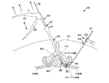
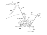
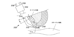
図2を参照すると、一実施例では、組織修正装置102は、近位部107と遠位部109を有する細長の本体108と、近位部107に連結された作動部106を有するハンドル104と、1以上の組織修正部材110と、1以上の保護面112とを具えている。様々な実施例では、これらの一部が以下にさらに説明され、修正装置102は、様々な導入方法、装置及びシステムを用いて、脊柱などの治療を施す領域に導入される。図2では、例えば、修正装置102は、患者の背中の第1の切開部240を通って脊髄中心管に配置された導入装置114を通って延在する。修正装置102は、ガイド部材116に沿って前進し、導入部材114を通り、椎間孔を通って2つの隣接する椎骨(1の椎骨のみが図2に示されている)の間に延在し、背中の第2(又は「遠位」)の切開部242から出る。いくつかの実施例では、図に示すように、ガイド部材は、ガイド部材116が組織を通って前進するのを容易にすべく、斜めの遠位先端部117を有する。   With reference to FIG. 2, in one embodiment, the tissue modification device 102 includes an elongated body 108 having a proximal portion 107 and a distal portion 109, and a handle 104 having an actuation portion 106 coupled to the proximal portion 107. One or more tissue correction members 110 and one or more protective surfaces 112 are provided. In various embodiments, some of these are described further below, and the modification device 102 is introduced into the area to be treated, such as the spine, using a variety of introduction methods, devices and systems. In FIG. 2, for example, the correction device 102 extends through a first incision 240 in the patient's back and through an introducer device 114 placed in the central spinal canal. The correction device 102 advances along the guide member 116 and extends through the introducer member 114, through the intervertebral foramen and between two adjacent vertebrae (only one vertebra is shown in FIG. 2). And exit the second (or “distal”) incision 242 in the back. In some embodiments, as shown, the guide member has an angled distal tip 117 to facilitate the advancement of the guide member 116 through tissue.

一般に、組織修正装置102は、組織修正部材110が、図2に示す湾曲した、厚い、又は突出する黄色靭帯組織などの修正されるターゲット組織に対向するように、脊柱内の位置に前進する。修正装置102は、組織修正部材110がターゲット組織に面するときに、保護面112が非ターゲット組織に面するように構成されている。保護面112は、単に細長の本体108の長さでもよく、又は拡張した直径、保護又は滑らかなコーティング、展開可能なバリア、薬剤溶出コーティング又はポート等の1以上の保護形状でもよい。いくつかの実施例では、保護面112は、「組織を修正しない」面として機能し、実質的に非ターゲット組織を修正しない。代替的な実施例では、保護面112は、1以上の保護薬を投与し、1以上のエネルギー形態を適用し、又は物理的なバリアを提供することなどにより、いくつかの積極的な方法で保護することにより、非ターゲット組織に影響を与えてもよい。   In general, the tissue modification device 102 is advanced to a position within the spinal column such that the tissue modification member 110 faces the target tissue to be modified, such as the curved, thick, or protruding ligamentum tissue shown in FIG. The correction device 102 is configured so that the protective surface 112 faces the non-target tissue when the tissue correction member 110 faces the target tissue. The protective surface 112 may simply be the length of the elongated body 108 or may be one or more protective shapes such as an expanded diameter, a protective or smooth coating, a deployable barrier, a drug eluting coating or a port. In some embodiments, protective surface 112 functions as a “do not modify tissue” surface and does not substantially modify non-target tissue. In alternative embodiments, the protective surface 112 may be applied in several positive ways, such as by administering one or more protective agents, applying one or more energy forms, or providing a physical barrier. Protecting may affect non-target tissues.

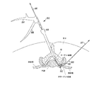
いくつかの実施例では、組織修正部材110がターゲット組織に面し、保護面112が非ターゲット組織に面するように、組織修正装置102が配置されると、固定力が、患者の体内又は体外で細長の本体108の遠位部109に又はこれの近くに加わる。また、張力は、ハンドル104を引っ張ることなどにより(一方向の矢印)、細長の本体108の近位部107に又はこれの近くに加わり、作動部106を用いて(二方向の矢印)組織修正部材110を作動させ、ターゲット組織を修正する。図示した例では、固定力が、ユーザの手244により遠位部109近くに加わり、ハンドル104が近位方向に引っ張られて(矢印)、張力を加える。代替的な実施例では、手224は、ガイド部材116の遠位部117又はこれの近くを把持し、これにより固定力を加え、また、細長の本体108に固定力を加える。このような実施例の位置の変更例では、細長の本体108又はハンドル104は、任意で調整可能にガイド部材116に締め付けて、細長の本体108に固定力を加えるのを強化又は促進してもよい。組織修正部材110による組織修正には、切断、除去、切開、修復、血流の低減、縮小、削ぎ、バーリング(burring)、かみつき(biting)、改造、生検、創面切除、溶解、減量、研磨、やすりがけ、平削り、加熱、冷却、蒸発、ターゲット組織に薬剤を送達、及び/又はターゲット組織を引っ込めることが含まれる。組織が修正されると、組織修正装置102及び任意の導入装置114、ガイド部材116、又は他の装置が患者から取り外される。   In some embodiments, when the tissue modification device 102 is positioned such that the tissue modification member 110 faces the target tissue and the protective surface 112 faces the non-target tissue, the fixation force is applied within or outside the patient. At or near the distal portion 109 of the elongated body 108. Tension is also applied to or near the proximal portion 107 of the elongate body 108, such as by pulling on the handle 104 (unidirectional arrow), and using the actuator 106 (bidirectional arrow) to modify tissue. Actuate member 110 to modify the target tissue. In the illustrated example, a securing force is applied near the distal portion 109 by the user's hand 244 and the handle 104 is pulled proximally (arrow) to apply tension. In an alternative embodiment, the hand 224 grips at or near the distal portion 117 of the guide member 116 thereby applying a locking force and applying a locking force to the elongated body 108. In such an example position change, the elongate body 108 or handle 104 may optionally be tightened to the guide member 116 to enhance or facilitate applying a securing force to the elongate body 108. Good. For tissue correction by the tissue correction member 110, cutting, removal, incision, repair, blood flow reduction, reduction, shaving, burring, biting, remodeling, biopsy, debridement, dissolution, weight loss, polishing , Sanding, planing, heating, cooling, evaporation, delivering a drug to the target tissue, and / or retracting the target tissue. Once the tissue is modified, the tissue modification device 102 and any introducer device 114, guide member 116, or other device is removed from the patient.

前記装置の様々な実施例では、組織修正部材110が、任意の好適な長さの本体108に沿って配置される。一実施例、例えば、脊柱の治療で用いられる巣越智の実施例などでは、組織修正部材110は、10cm以下の、好適には6cm以下の、さらに好適には3cm以下の装置の長さに沿って配置される。様々な実施例では、組織修正部材110は、ロンジュール、キューレット、メス、1以上の切断ブレード、ハサミ、鉗子、プローブ、鬼目やすり、やすり、研磨部材、1以上の小さな面、電気外科手術装置、双極電極、単極電極、熱電極、回転式電力機構シェーバ、往復式電力機構シェーバ、電力機構ばり(burr)、レーザ、超音波水晶、低温プローブ、加圧されるウォータジェット、投薬部材、針、針電極、またはこれらの組み合わせを具えてもよい。様々な実施例では、総ての組織修正部材110は、細長の本体に対して移動可能でもよく、総てが静止してもよく、又は一部が移動可能で一部が静止してもよい。これらの及び他の態様及び実施例は、以下にさらに説明される。   In various embodiments of the device, the tissue modification member 110 is disposed along the body 108 of any suitable length. In one embodiment, such as the Nichigochi embodiment used in spinal column treatment, the tissue modifying member 110 is along the length of the device of 10 cm or less, preferably 6 cm or less, more preferably 3 cm or less. Arranged. In various embodiments, the tissue modification member 110 may be a long joule, a curette, a scalpel, one or more cutting blades, scissors, forceps, a probe, a demon eye file, a file, an abrasive member, one or more small surfaces, an electrosurgical procedure. Device, bipolar electrode, monopolar electrode, thermal electrode, rotary power mechanism shaver, reciprocating power mechanism shaver, power mechanism burr, laser, ultrasonic crystal, cryogenic probe, pressurized water jet, dosing member, A needle, a needle electrode, or a combination thereof may be provided. In various embodiments, all tissue modifying members 110 may be movable relative to the elongated body, may all be stationary, or may be partially movable and partially stationary. . These and other aspects and examples are further described below.

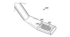
ここで、図3Aから3Iに戻ると、組織修正装置102の一実施例のさらに詳細な図が示されている。図3Aを参照すると、組織修正装置102は、近位部107と遠位部109を有する細長の本体108と、細長の本体108に沿って配置された開口111と、窓111により露出される2つの組織修正ブレード110と、近位部107に連結された作動部106を有するハンドル104とを具えている。図示した実施例では、組織修正部材がブレード110を具えているが、代替的な実施例では、他の組織修正部材を追加又は置換してもよい。   Turning now to 3I from FIGS. 3A, a more detailed view of one embodiment of the tissue modification device 102 is shown. Referring to FIG. 3A, the tissue modification device 102 is exposed by an elongated body 108 having a proximal portion 107 and a distal portion 109, an opening 111 disposed along the elongated body 108, and a window 111. And includes a tissue modification blade 110 and a handle 104 having an actuating portion 106 coupled to the proximal portion 107. In the illustrated embodiment, the tissue modifying member comprises a blade 110, but in alternative embodiments, other tissue modifying members may be added or replaced.

様々な実施例では、細長の本体108は、様々な大きさ、形状、外形、可撓性の程度を有していてもよい。例えば、湾曲した形状の遠位部109が示されており、細長の本体108の少なくとも一部が可撓性を有することが示されている。様々な実施例では、細長の本体108は、円形、卵形、楕円、平ら、反った平ら、長方形、四角形、三角形、対称又は非対称の断面形状のうち1以上を有してもよい。図3C及び3Dに示すように、図示した実施例では、細長の本体108が、相対的に平らな構成を有しており、ターゲット組織と非ターゲット組織の間に本体108を配置するのを容易にする。本体108の遠位部109は先が細くなっており、狭い空間や患者の皮膚の切開部を通過するのを容易にする。本体108は、開口111とブレードの領域に周囲に僅かに拡張した部分を具えてもいる。脊柱内の組織を修正するのに用いられる実地例などの一実施例では、本体108は、長さに沿った任意の位置で10mm以下の高さと、長さに沿った任意の位置で20mm以下の幅とを有し、又はさらに好適には長さに沿った任意の位置で2mm以下の高さと、長さに沿った任意の位置で4mm以下の幅を有する小さな外形を有する。本体108は、患者の第1の切開部を通ってターゲット組織と非ターゲット組織との間を延在し、患者の第2の切開部から出るほど十分な長さを有する。代替的には、本体108は、第1の切開部を通ってターゲット組織と非ターゲット組織との間の患者の体内の固定位置を延在してもよい。別の代替的な実施例では、本体108は、第1の切開部を通って、ターゲット組織と非ターゲット組織との間の患者の体内の近くではあるがターゲット組織から遠位の位置に延在し、組織修正装置102の一部がガイド部材116に固定された状態である。いくつかの実施例では、細長の本体108は、本体がガイドワイヤ又は他のガイド部材上を通過し、あるいは1以上のガイド部材が本体108上又は本体108内を通過可能にする少なくとも位置の特徴を具えている。例えば、様々な実施例では、本体108は、1以上のガイドワイヤルーメン、レール、トラック、縦方向のくぼみ、又はこれらの組み合わせを有してもよい。   In various embodiments, the elongated body 108 may have various sizes, shapes, profiles, and degrees of flexibility. For example, a curved shaped distal portion 109 is shown and at least a portion of the elongated body 108 is shown to be flexible. In various embodiments, the elongate body 108 may have one or more of circular, oval, elliptical, flat, warped flat, rectangular, square, triangular, symmetric or asymmetric cross-sectional shape. As shown in FIGS. 3C and 3D, in the illustrated embodiment, the elongate body 108 has a relatively flat configuration to facilitate placement of the body 108 between target and non-target tissue. To. The distal portion 109 of the body 108 is tapered to facilitate passage through confined spaces and incisions in the patient's skin. The body 108 also includes a slightly expanded portion around the opening 111 and blade region. In one embodiment, such as a practical example used to modify tissue in the spinal column, the body 108 has a height of 10 mm or less at any position along the length and 20 mm or less at any position along the length. Or, more preferably, a small profile having a height of 2 mm or less at any position along the length and a width of 4 mm or less at any position along the length. The body 108 extends between the target tissue and the non-target tissue through the first incision in the patient and is long enough to exit from the second incision in the patient. Alternatively, the body 108 may extend a fixed location within the patient's body between the target tissue and the non-target tissue through the first incision. In another alternative embodiment, the body 108 extends through the first incision near the patient's body between the target tissue and the non-target tissue but distally from the target tissue. In addition, a part of the tissue correction device 102 is fixed to the guide member 116. In some embodiments, the elongated body 108 has at least positional features that allow the body to pass over a guidewire or other guide member, or to allow one or more guide members to pass over or within the body 108. It has. For example, in various embodiments, the body 108 may have one or more guidewire lumens, rails, tracks, longitudinal depressions, or combinations thereof.

一実施例では、細長の本体108は、その長さに沿って主に可撓性を有し、薄くて可撓性のある金属、プラスチック樹脂、織物等などの好適な可撓性のある素材を具えている。いくつかの実施例では、好ましくない細長の本体108の湾曲又は捻れを引き起こすことなく、押す能力を本体108の一部に与えるために、又は組織修正部材110に力を加えるために細長の本体108に1以上の硬質の部分を具えることが有益である。このような実施例では、素材を本体108に追加し、又は硬質な部分を厚くし若しくは広くし、又は違う形状にすることにより強度を与える。   In one embodiment, the elongate body 108 is primarily flexible along its length, and is a suitable flexible material such as a thin and flexible metal, plastic resin, fabric, etc. It has. In some embodiments, the elongated body 108 is provided to provide a pushing ability to a portion of the body 108 or to apply force to the tissue modifying member 110 without causing undesirable bending or twisting of the elongated body 108. It may be beneficial to have one or more hard parts. In such embodiments, the strength is provided by adding material to the body 108, or by thickening or widening the hard part, or by taking a different shape.

ハンドル104は、様々な実施例に係る好適な構成を有してもよい。同様に、作動部106は、様々な実施例の多くの作動部を具えてもよい。図3Aに示す実施例では、作動部106は、トリガ又は移動ハンドル部分を具えており、ユーザにより把持され、ハンドル104に向かって引っ張られ又は押し込められ、ブレード110が一体になり、組織を切断する。代替的な実施例では、作動部106は代わりに、無線周波数による外科的アブレーション組織修正部材を作動させるスイッチ又はボタンを具えてもよい。さらに別の実施例では、作動部106が、トリガとスイッチの組み合わせ、1以上の引っ張りワイヤ、任意の形状のレバー、及び/又はこれらの組み合わせを具えてもよい。   The handle 104 may have any suitable configuration according to various embodiments. Similarly, the actuating portion 106 may comprise many actuating portions of various embodiments. In the embodiment shown in FIG. 3A, the actuator 106 includes a trigger or moving handle portion that is grasped by the user and pulled or pushed toward the handle 104 to unite the blade 110 and cut tissue. . In an alternative embodiment, the actuator 106 may alternatively include a switch or button that activates a radio frequency surgical ablation tissue modification member. In yet another embodiment, the actuator 106 may comprise a trigger and switch combination, one or more pull wires, any shape lever, and / or combinations thereof.

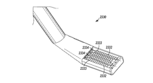
図3Bから図3Dは、組織修正装置102の一部を詳細に示している。これらの図では、開口111及びブレード110がより鮮明に示されている。一実施例では、細長の本体108とブレード110の少なくとも一方が、僅かに湾曲した構成を具えている。代替的な実施例では、細長の本体109とブレード110の少なくとも一方が平らでもよい。他の代替的な実施例では、ブレード110などの組織修正部材は、細長の本体108に対して盛り上がっていてもよい。   3B to 3D show a part of the tissue correction device 102 in detail. In these figures, the opening 111 and the blade 110 are more clearly shown. In one embodiment, at least one of the elongate body 108 and the blade 110 has a slightly curved configuration. In alternative embodiments, at least one of the elongated body 109 and the blade 110 may be flat. In other alternative embodiments, a tissue modifying member such as blade 110 may be raised relative to the elongated body 108.

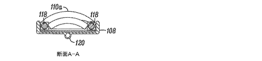
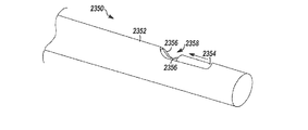
ブレード110は、細長の本体108の開口111の遠位端及び近位端にそれぞれある遠位ブレード110aと近位ブレード110bとを具えている。本体108の開口111は、装置がターゲット組織の部位の表面に強制的に押しつけられるときに、軟らかい組織と硬い組織双方を適応させる。図3Cに示す細長の本体108の遠位部の平面図は、遠位ブレード110aの角度の付いた縁部と近位ブレード110bを示しており、これらはターゲット組織の切断を容易にする。代替的な実施例では、ブレード110は、様々な代替的な形状と構成を具えてもよい。本体108の遠位部は、図3Dの側面図に示すように非常に低い外形(幅と比較した高さ)を有しており、この図では、ブレード110のみが、細長の本体109の上面から突出している。一実施例では、図3Dに示すように、ガイドワイヤチューブ120(又はルーメン)が、細長の本体108下側面から延在している(又はこれに連結されている)。細長の本体108の下側面は、保護面又は組織を修正しない面の例である。   The blade 110 includes a distal blade 110a and a proximal blade 110b at the distal and proximal ends of the opening 111 of the elongate body 108, respectively. The opening 111 in the body 108 accommodates both soft and hard tissue when the device is forced against the surface of the target tissue site. The plan view of the distal portion of the elongated body 108 shown in FIG. 3C shows the angled edge of the distal blade 110a and the proximal blade 110b, which facilitate cutting of the target tissue. In alternative embodiments, the blade 110 may have a variety of alternative shapes and configurations. The distal portion of the body 108 has a very low profile (height compared to the width) as shown in the side view of FIG. 3D, in which only the blade 110 is the top surface of the elongated body 109. Protruding from. In one embodiment, as shown in FIG. 3D, a guide wire tube 120 (or lumen) extends from (or is connected to) the lower side of the elongated body 108. The underside of the elongated body 108 is an example of a protective surface or a surface that does not modify tissue.

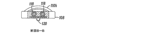
一実施例では、遠位のブレード110aが、図3C、3E及び3Fに示すように、2つの引っ張りワイヤ118を用いて連結されている。ハンドル104に連結され、作動部106により移動する引っ張りワイヤ118は、遠位ブレード110aを近位方向に移動させ、近位ブレード110bの切断縁部に接触し、これにより組織を切断する。好適な作動部に連結され、ブレード110を駆動するギア、リボン若しくはベルト、磁石、電力、形状記憶合金、電磁気ソレノイド等の他の代替的な機構を代替的な実施例で使用してもよい。前述したように、一実施例では、遠位ブレード110a及び/又は近位ブレード110bは、その切断縁部に沿って外側に湾曲した形状を有してもよい。代替的に、遠位ブレード110aは、平ら、長方形、V字型、及び内側に湾曲した形状を含む(凹面対凸面)様々なブレードの形状を具えてもよい。一方のブレード110の切断縁は、簡単な斜面又は面により形成される鋭利な縁部を有する。代替的又は付加的に、切断縁部は、対向するブレードの切断縁部と係合する歯形の部材を有してもよく、又は、波形の隆起、鋸歯、やすり状の形状等を有してもよい。様々な実施例では、ブレード110双方が鋭利でもよく、又は一方のブレード110が鋭利で、他方がほぼ平らで、鋭利なブレード110が切断する表面を有してもよい。代替的又は付加的に、双方の切断縁部は硬さが均一であり、又は第1の切断縁部は、第2の切断縁部よりも硬くてもよく、後者は、第1の硬い縁部からの力の影響を受け、ターゲット組織の切断を容易にする。   In one embodiment, the distal blade 110a is connected using two pull wires 118 as shown in FIGS. 3C, 3E and 3F. A puller wire 118 coupled to the handle 104 and moved by the actuator 106 moves the distal blade 110a proximally and contacts the cutting edge of the proximal blade 110b, thereby cutting tissue. Other alternative mechanisms, such as gears, ribbons or belts, magnets, power, shape memory alloys, electromagnetic solenoids, etc., coupled to a suitable actuator and driving the blade 110 may be used in alternative embodiments. As described above, in one embodiment, the distal blade 110a and / or the proximal blade 110b may have an outwardly curved shape along its cutting edge. Alternatively, the distal blade 110a may comprise a variety of blade shapes including flat, rectangular, V-shaped, and inwardly curved shapes (concave vs. convex). The cutting edge of one blade 110 has a sharp edge formed by a simple bevel or surface. Alternatively or additionally, the cutting edge may have a toothed member that engages the cutting edge of the opposing blade, or has a corrugated ridge, sawtooth, file-like shape, etc. Also good. In various embodiments, both blades 110 may be sharp, or one blade 110 may be sharp and the other may be substantially flat and the sharp blade 110 may have a surface to cut. Alternatively or additionally, both cutting edges are uniform in hardness, or the first cutting edge may be harder than the second cutting edge, the latter being the first hard edge The target tissue is easily cut by the influence of the force from the part.

図3E及び3Fは、図3Cの線A−A及びB−B上の細長の本体の断面図である。いくつかの実施例では、図3Eに示す下側面のような細長の本体108の総て又は一部は、手術空間及び身体構造上の位置で器具の操作を容易にするために、滑らかな表面を具えてもよい。また、滑らかな下側面は、ブレード110と手術空間内の非ターゲット組織との間のバリアを提供する。下側面は、ガイドワイヤ又は他のアクセス装置又はレールを適応させるためにガイド部材ルーメン120を具えてもよい。図3Eは、引っ張りワイヤ118により連結された遠位ブレード110を示している。図3Fは、近位ブレード110bを示しており、これは、引っ張りワイヤ118により連結されず、本体108に固定される。様々な代替的な実施例では、近位ブレード110bは、遠位方向に移動可能であり、遠位ブレード110aは静止しており、双方のブレードは互いに対して移動してもよく、又はバックストップに向かって引っ張られる1のブレード又は1以上が移動可能な2以上のブレードなどの様々なブレードを用いてもよい。様々な代替的な実施例では、ガイド部材ルーメン120は、細長の本体108の側面又は中心に提供してもよい。さらなる代替的な実施例では、1以上のガイド部材ルーメン120は、1以上の様々な断面形状、例えば、ほぼ円形、ほぼ卵形、又はほぼ長方形をしていてもよく、代替的なガイド部材、例えば平ら又は長方形のガイドワイヤ、針、又はレールに適応させる。さらに他の代替的な実施例では、ガイド部材ルーメン120は、細長の本体108により調整可能に連結してもよく、細長の本体108、したがって、ガイド部材に対する組織修正部材110の位置の操作を可能にする。   3E and 3F are cross-sectional views of the elongate body on lines AA and BB in FIG. 3C. In some embodiments, all or a portion of the elongate body 108, such as the lower side shown in FIG. 3E, is a smooth surface to facilitate operation of the instrument in a surgical space and anatomical location. May be included. The smooth lower surface also provides a barrier between the blade 110 and non-target tissue in the surgical space. The underside may include a guide member lumen 120 to accommodate a guide wire or other access device or rail. FIG. 3E shows the distal blade 110 connected by a pull wire 118. FIG. 3F shows a proximal blade 110 b that is not connected by a pull wire 118 and is secured to the body 108. In various alternative embodiments, the proximal blade 110b is movable in the distal direction, the distal blade 110a is stationary, both blades may move relative to each other, or backstop Various blades may be used, such as one blade pulled towards or two or more blades in which one or more are movable. In various alternative embodiments, the guide member lumen 120 may be provided on the side or center of the elongated body 108. In further alternative embodiments, the one or more guide member lumens 120 may have one or more different cross-sectional shapes, such as substantially circular, generally oval, or generally rectangular, For example, adapt to flat or rectangular guide wires, needles or rails. In yet another alternative embodiment, the guide member lumen 120 may be adjustably coupled by the elongated body 108, allowing manipulation of the position of the tissue modifying member 110 relative to the elongated body 108 and thus the guide member. To.

ここで図3Gから3Iを参照すると、ブレード110が閉じた状態で示されている。一実施例では、遠位ブレード110aが近位方向に引っ張られて組織を切断するとき、切断された組織のすくなくとも一部が、細長の本体108の中空の内側部分に捕獲される。様々な実施例はさらに、カバー、切断組織ハウジング及び/又は切断された組織及び/又は組織の破片を収集するための同様のものを具えてもよい。次に、このような収集された組織及び破片が、組織を修正する処置の間又はその後に患者から取り出される。所定の組織を修正する処置の間、遠位方向に引っ張ることができる遠位ブレード110aは、近位方向に引っ張られて組織を切断し、近位方向に引っ張られ、所望の量の組織を切断するために必要な回数さらに組織を切断する。   Referring now to FIGS. 3G-3I, the blade 110 is shown closed. In one example, when distal blade 110a is pulled proximally to cut tissue, at least a portion of the cut tissue is captured in the hollow inner portion of elongated body 108. Various embodiments may further comprise a cover, a cut tissue housing, and / or the like for collecting cut tissue and / or tissue fragments. Such collected tissue and debris is then removed from the patient during or after the tissue modification procedure. During a procedure that modifies a given tissue, the distal blade 110a, which can be pulled in a distal direction, is pulled proximally to cut tissue and pulled proximally to cut a desired amount of tissue. Cut the tissue further as many times as necessary.

ブレード110は、好適な金属、ポリマー、セラミック、又はこれらの組み合わせから作られる。好適な金属には、例えば、ステンレス鋼(303、304、316、316L)、ニッケルチタニウム合金、タングステンカーバイド合金、又はコバルトクロミウム合金、例えば、Elgiloy(登録商標)(米国イリノイ州エルジン所在のElgin Specially Metals)、Conichrome(登録商標)(米国ペンシルバニア州リーディング所在のCarpenter Technology)、又はPhynox(登録商標)(仏国パリ所在のImphy SA)が含まれるが、これらに限られない。いくつかの実施例では、ブレード、又はブレードの部分若しくはコーティングの素材は、電気伝導性又は耐熱特性により選択される。好適なポリマーには、ナイロン、ポリエステル、Darcon(登録商標)、ポリエチレン、アセタール、Delrin(登録商標)(独国ウィルミントン所在のDuPont)、ポリカーボネート、ナイロン、ポリエーテルエーテルケトン(PEEK)、ポリエーテルケトンケトン(PEKK)が含まれるがこれらに限られない。いくつかの実施例では、ポリマーにガラスが充填され、強度及び剛性が増加される。セラミックには、アルミナ、ジルコニア、及びカーバイドが含まれるがこれらに限られない。様々な実施例では、ブレード110は、金属射出成形(MIM)、CNC機械加工、射出成形、及び/又は研削等を用いて製造してもよい。引っ張りワイヤ118は金属又はポリマーで作ってもよく、また円形、卵形、長方形、四角形、又は編み目状の断面でもよい。いくつかの実施例では、引っ張りワイヤ118の直径は、約0.001から0.050インチ、さらに好適には約0.010から0.020インチの範囲でもよい。   The blade 110 is made from a suitable metal, polymer, ceramic, or combination thereof. Suitable metals include, for example, stainless steel (303, 304, 316, 316L), nickel titanium alloy, tungsten carbide alloy, or cobalt chromium alloy, such as Elgiloy® (Elgin Special Metals, Elgin, Illinois, USA). ), Conichrome® (Carpenter Technology, Reading, Pennsylvania, USA), or Phynox® (Imphy SA, Paris, France). In some embodiments, the blade, or part of the blade or the coating material, is selected for its electrical conductivity or heat resistance characteristics. Suitable polymers include nylon, polyester, Darcon®, polyethylene, acetal, Delrin® (DuPont, Wilmington, Germany), polycarbonate, nylon, polyetheretherketone (PEEK), polyetherketone Ketone (PEKK) is included, but is not limited to these. In some embodiments, the polymer is filled with glass to increase strength and stiffness. Ceramics include but are not limited to alumina, zirconia, and carbide. In various embodiments, the blade 110 may be manufactured using metal injection molding (MIM), CNC machining, injection molding, and / or grinding. The pull wire 118 may be made of metal or polymer, and may have a circular, oval, rectangular, square, or knitted cross section. In some embodiments, the diameter of the puller wire 118 may range from about 0.001 to 0.050 inches, more preferably from about 0.010 to 0.020 inches.

治療又は修正される組織に応じて、作動ブレード110(又は代替的な実施例の他の組織修正部材)が、様々な好適な長さを有する領域に沿ってターゲット組織を修正する。使用時には、ブレード110又は他の組織修正部材の動作範囲を所望の組織の長さに制限することが有利であり、これによりブレード110がその長さを超えて組織に影響を及ぼすことができない。このようにブレードの影響を制限することにより、周囲の組織及び構造の好ましくない修正又は損傷が制限され、又は阻止される。例えば、組織修正装置を利用して脊柱内の組織を修正する一実施例では、ブレード110は、10cm以下、好適には6cm以下、さらに好適には3cm以下のターゲット組織の長さに沿って動作する。もちろん、他の組織を扱う本体の他の部分では、異なる組織修正装置を用いてもよく、組織修正部材は、異なる活動の長さを有してもよい。一実施例では、ブレード110などの組織修正部材のターゲット組織に対する適切な配置を容易にすべく、このような目的を意図する組織修正部材及び/又は細長の本体及び/又は1以上の追加の特徴は、X線、フルオロスコープ、磁気共鳴又は超音波画像診断技術により容易に特定可能な素材で構成してもよい。   Depending on the tissue to be treated or modified, the actuating blade 110 (or other tissue modifying member of an alternative embodiment) modifies the target tissue along regions having various suitable lengths. In use, it is advantageous to limit the operating range of the blade 110 or other tissue modifying member to the desired tissue length so that the blade 110 cannot affect the tissue beyond that length. By limiting the influence of the blade in this way, undesirable modification or damage of the surrounding tissue and structure is limited or prevented. For example, in one embodiment that utilizes tissue modification devices to modify tissue in the spinal column, the blade 110 operates along a target tissue length of 10 cm or less, preferably 6 cm or less, and more preferably 3 cm or less. To do. Of course, other tissue modification devices may be used in other parts of the body that handle other tissues, and the tissue modification members may have different lengths of activity. In one embodiment, a tissue modifying member and / or an elongated body and / or one or more additional features intended for such purpose are intended to facilitate proper placement of a tissue modifying member, such as blade 110, relative to a target tissue. May be made of a material that can be easily identified by X-ray, fluoroscope, magnetic resonance, or ultrasonic diagnostic imaging techniques.

様々な実施例では、様々な技術を用いてブレード110(又は他の組織修正部材)がターゲット組織を超えて有意に延在するのを阻止する。例えば、ブレード110がターゲット組織を超えて有意に延在する一実施例では、ブレード110を作動させる間に、装置102が近位部分に向かって又は遠位部分に向かって移動するのを阻止すべく、完全に安定するように組織修正装置102を保持する必要がある。装置102を静止した状態で保持することは、さらに以下に説明するように、装置の一方の端部を固定し、他方の端部に又はこれの近くに張力を加えることにより実現される。   In various embodiments, various techniques are used to prevent the blade 110 (or other tissue modifying member) from extending significantly beyond the target tissue. For example, in one embodiment where blade 110 extends significantly beyond the target tissue, device 102 is prevented from moving toward the proximal portion or toward the distal portion while actuating blade 110. Therefore, it is necessary to hold the tissue correction device 102 so as to be completely stable. Holding the device 102 stationary is accomplished by securing one end of the device and applying tension to or near the other end, as further described below.

図3A〜3Iに示す実施例では、引っ張りワイヤ118は、作動部106を近位方向に握ることにより近位方向に引っ込められる。代替的な実施例では、作動部106を握ることにより、両方のブレード110が内側に移動し、開口111のほぼ中央で接する。さらなる実施例では、遠位ブレード110aは、例えば、遠位ワイヤに取り付けられた遠位作動部を用いることにより、又は遠位ブレード110aに取り付けられた遠位ガイド部材を引っ張ることにより、装置102の遠位端部から生じる引っ張り力により開始位置に戻してもよい。さらに別の実施例では、近位ブレード110bは、例えば、遠位ワイヤに取り付けられた遠位の作動部を用いることにより、又は近位ブレード110bに取り付けられた遠位ガイド部材を引っ張ることにより、装置102の遠位端部から生じる引っ張り力により移動して切断してもよい。さらに別の実施例では、作動部106を握ることにより、近位ブレード110bが遠位方向に移動するとともに、遠位ブレード110aが固定される。他の代替的な実施例では、1以上のブレード110は左右に移動してもよく、1以上のブレード110は、作動時に開口111から飛び出し、滑動し、又は上下してもよく、又は1以上のブレード110は、開口を介して拡張してもよい。別の実施例では、1以上のブレード110及び/又は装置102の他の組織修正部材は、ターゲット組織を切断し、削り、砕き、研磨し、及び/又は切除するように構成した動力装置でもよい。他の実施例では、1以上のブレードは、無線周波数(RF)又は耐熱装置などのエネルギー伝達装置に連結させて、切断し、除去し、収縮させ、切開し、固め、又は加熱するためにブレードにエネルギーを供給して、組織の修正を促進してもよい。別の実施例では、鬼目やすり又はやすりを1以上のブレードとともに、又はこれに連結して使用してもよい。これらの実施例のいずれかは、作動部106及び1以上の移動ブレード110は、組織修正装置102の相対的に小さな全体の移動又は他の動作により組織を修正する。したがって、ターゲット組織は、ブレード110を延在させることなく、又は他の組織修正部材が治療されるターゲット組織の領域を有意に超えることなく修正してもよい、   In the embodiment shown in FIGS. 3A-3I, the puller wire 118 is retracted proximally by grasping the actuator 106 proximally. In an alternative embodiment, grasping the actuating portion 106 causes both blades 110 to move inward and meet approximately at the center of the opening 111. In a further embodiment, the distal blade 110a may be configured with the device 102 by, for example, using a distal actuator attached to the distal wire or by pulling a distal guide member attached to the distal blade 110a. The starting position may be returned by a pulling force generated from the distal end. In yet another example, the proximal blade 110b may be used, for example, by using a distal actuator attached to the distal wire or by pulling a distal guide member attached to the proximal blade 110b. The device 102 may be moved and cut by a pulling force generated from the distal end of the device 102. In yet another embodiment, grasping the actuating portion 106 moves the proximal blade 110b in the distal direction and secures the distal blade 110a. In other alternative embodiments, one or more blades 110 may move from side to side, one or more blades 110 may jump out of opening 111, slide, or move up and down, or one or more The blade 110 may extend through the opening. In another example, one or more blades 110 and / or other tissue modifying members of the device 102 may be a power device configured to cut, sharpen, crush, polish, and / or cut the target tissue. . In other embodiments, one or more blades are coupled to an energy transfer device, such as a radio frequency (RF) or heat resistant device, to cut, remove, shrink, incise, incise, consolidate, or heat the blade. May be supplied with energy to facilitate tissue modification. In another embodiment, a demon file or file may be used with or coupled to one or more blades. In any of these embodiments, the actuator 106 and the one or more moving blades 110 modify tissue by a relatively small overall movement or other action of the tissue modification device 102. Thus, the target tissue may be modified without extending the blade 110 or without significantly exceeding the area of the target tissue where other tissue modifying members are treated.

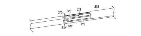
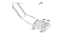
ここで図4Aから4Cを参照すると、代替的な実施例では、組織修正装置202は、近位部と遠位部209を有する細長の本体208と、ハンドル204と、近位部と連結された作動部206と、開口部211と、遠位部209近くに配置される組織修正部材210とを具えている。図4B及び4Cに明示するように、図示した実施例では、組織修正部材210が、RF電極ワイヤループを具えている。ワイヤループ210は、電気手術分野で通常用いられ知られている任意の好適なRF電極を具えてもよく、Gyrus Medical社(モンゴル所在のMaple Grove)が提供するRF生成器などの内蔵又は外付けRF生成器により動力を供給してもよい。様々な実施例では、様々な範囲の無線周波数を用いてもよい。例えば、いくつかの実施例は、約70ヘルツと約5メガヘルツの範囲のRFエネルギーを使用してもよい。いくつかの実施例では、RFエネルギーのパワーレンジは、約0.5ワットから約200ワットでもよい。さらに、様々な実施例では、RF電流を伝導性のある組織に直接送達してもよく、又はいくつかの実施例では加熱され、蒸発され、ターゲット組織を修正するプラズマに変換されるサリン又はLactate Ringer溶液などの伝導性の媒体に送達してもよい。遠位部209は、前述したのと同じような先細の先端部を具え、細長の本体208が細い身体構造の部位を通過するのを容易にしてもよい。ハンドル204及び作動部206は前述したのと同様であるが、図4Aから4Cの実施例では、作動部206を用いてワイヤループ210の直径を変化させてもよい。作動部206を用いて、ワイヤループ210を開口211から延在させ、拡張させ、引っ込ませ、移動させてもよい。いくつかの実施例は任意で、RF生成器を作動させてRF電流を電極に送達するフットスイッチなどの第2の作動部を具えてもよい。   4A-4C, in an alternative embodiment, the tissue modification device 202 is coupled to an elongated body 208 having a proximal portion and a distal portion 209, a handle 204, and the proximal portion. It comprises an actuating portion 206, an opening 211, and a tissue modifying member 210 disposed near the distal portion 209. As clearly shown in FIGS. 4B and 4C, in the illustrated embodiment, tissue modifying member 210 comprises an RF electrode wire loop. The wire loop 210 may comprise any suitable RF electrode commonly used and known in the electrosurgical field, such as an internal or external RF generator such as that provided by Gyrus Medical (Maple Grove, Mongolia). Power may be supplied by an RF generator. Various embodiments may use various ranges of radio frequencies. For example, some embodiments may use RF energy in the range of about 70 hertz and about 5 megahertz. In some embodiments, the RF energy power range may be about 0.5 watts to about 200 watts. Further, in various embodiments, RF current may be delivered directly to conductive tissue, or in some embodiments, sarin or lactate that is heated, evaporated, and converted to a plasma that modifies the target tissue. It may be delivered to a conductive medium such as a Ringer solution. The distal portion 209 may have a tapered tip similar to that described above to facilitate the elongate body 208 passing through a portion of a thin body structure. Handle 204 and actuating portion 206 are similar to those described above, but in the embodiment of FIGS. 4A-4C, actuating portion 206 may be used to vary the diameter of wire loop 210. Actuator 206 may be used to extend, expand, retract, and move wire loop 210 from opening 211. Some embodiments may optionally include a second actuator, such as a foot switch, that activates the RF generator to deliver RF current to the electrodes.

細長の本体208は、好適な素材から製造してもよく、様々な構成を有してもよい。一実施例では、本体208が、(チューブを平らな形状に展開する、図示せず)全層スリット又は硬化部材(図示せず)を有する金属チューブを具えている。スリットチューブは、簡単な製造処理と、双極のRF処理の伝導性のある経路を提供する。   The elongated body 208 may be manufactured from a suitable material and may have a variety of configurations. In one embodiment, the body 208 comprises a metal tube having a full thickness slit (not shown) or a stiffening member (not shown) that unfolds the tube into a flat shape. Slit tubes provide a simple manufacturing process and a conductive path for bipolar RF processing.

図4Cを参照すると、絶縁体222は、ワイヤループ210の部分の周囲に配置され、組織を修正ためにワイヤループ210の所望の部分のみがRF電流を組織に伝達する。絶縁体222に覆われたワイヤループ210は、サポートチューブ218に近位方向に延在する。様々な代替的な実施例では、電極による組織修正部材(ワイヤループ210は一例である)は、二極式又は単極式でもよい。例えば、図4Cに示すように、開口211の遠位部に向かって収容されたスリーブ224は、二極式装置のワイヤループ210用の対極板として機能する。ワイヤループ電極210は、ステンレス鋼合金、ニッケルチタニウム合金、チタニウム合金、タングステン合金等の様々な伝導性の金属から作ってもよい。絶縁体222は、ポリイミド、ポリエーテルエーテルケトン(PEEK)、ポリエーテルケトンケトン(PEKK)、ポリアミドイミド等などの熱及び電気的に安定したポリマーから作ることができ、任意で強化した繊維でもよく、又は剛性及び強度を付加する編成物を含んでもよい。代替的な実施例では、絶縁体222は、セラミックベースの素材で構成してもよい。   Referring to FIG. 4C, insulator 222 is placed around a portion of wire loop 210 and only the desired portion of wire loop 210 conducts RF current to the tissue to modify the tissue. The wire loop 210 covered by the insulator 222 extends proximally to the support tube 218. In various alternative embodiments, the electrode tissue modifying member (wire loop 210 is an example) may be bipolar or monopolar. For example, as shown in FIG. 4C, the sleeve 224 housed toward the distal portion of the opening 211 functions as a counter electrode plate for the wire loop 210 of the bipolar device. The wire loop electrode 210 may be made from various conductive metals such as stainless steel alloys, nickel titanium alloys, titanium alloys, tungsten alloys and the like. The insulator 222 can be made from a thermally and electrically stable polymer such as polyimide, polyetheretherketone (PEEK), polyetherketoneketone (PEKK), polyamideimide, etc., and may be optionally reinforced fiber, Alternatively, a knitted fabric that adds rigidity and strength may be included. In alternative embodiments, the insulator 222 may be composed of a ceramic-based material.

一実施例では、ワイヤループ210は、組織修正装置202を患者の体内に送達する際に細長の本体208内に収容され、次に、本体208の残りの部分に対して開口211から外側に延在し、組織を除去する。ワイヤループ210は、開口211から飛び出る又は上下し、堅い組織の表面に接触するときに影響を及ぼすように可撓性を有していてもよい。ワイヤループ210は、湾曲、平ら、螺旋、又は波状の様々な形状でもよい。ワイヤループ210は、本体208の幅と同様の直径を有しており、代替的な実施例では、開口211から延在するときに拡張し、本体208の直径よりも小さい又は大きい直径を有していてもよい。引っ張りワイヤ(図示せず)は、前述した方法と同じ方法で近位方向に引っ張ってもよく、ワイヤループ210を潰し、ワイヤループ210の直径を減少させてその外形を低くし、及び/又はワイヤループ210を近位方向に引っ張って組織を除去し、又は本体208内に収容する。収縮したワイヤループ210の低い外形は、組織修正の前後で組織修正202の挿入及び取り外しを容易にする。ワイヤループ210の直径が減少すると、サポートチューブ218は細長の本体208の中心に向かって偏向する。   In one embodiment, the wire loop 210 is housed within the elongate body 208 upon delivery of the tissue modification device 202 into the patient's body and then extends outwardly from the opening 211 relative to the remainder of the body 208. And remove the tissue. The wire loop 210 may be flexible so as to jump out or open up and down from the opening 211 and affect when contacting a hard tissue surface. The wire loop 210 may have various shapes such as curved, flat, spiral, or wavy. The wire loop 210 has a diameter similar to the width of the body 208, and in an alternative embodiment, expands when extending from the opening 211 and has a diameter that is smaller or larger than the diameter of the body 208. It may be. A puller wire (not shown) may be pulled proximally in the same manner as described above, crushing the wire loop 210, reducing the diameter of the wire loop 210 to lower its profile, and / or wire The loop 210 is pulled proximally to remove tissue or housed within the body 208. The low profile of the deflated wire loop 210 facilitates insertion and removal of the tissue modification 202 before and after tissue modification. As the diameter of the wire loop 210 decreases, the support tube 218 deflects toward the center of the elongated body 208.

代替的な実施例(図示せず)では、組織修正装置202は、複数のRFワイヤループ210又は他のRF部材を具えてもよい。別の実施例では、装置202は、1以上のブレードとRFワイヤループ210を具えてもよい。このような実施例では、ワイヤループ210は、黄色靭帯などの柔らかい組織を除去又は修正するのに、又は止血するのに用いてもよく、またブレードは、骨などの硬い組織を修正するのに用いてもよい。他の実施例は、以下にさらに説明するように、一の処置で2つの個別の組織修正(又は2以上の装置)を用いて様々な種類の組織を修正し、一種類の組織の修正を強化等してもよい。   In alternative embodiments (not shown), the tissue modification device 202 may comprise a plurality of RF wire loops 210 or other RF members. In another example, the device 202 may include one or more blades and an RF wire loop 210. In such embodiments, the wire loop 210 may be used to remove or modify soft tissue such as the yellow ligament, or to stop hemostasis, and the blade may be used to modify hard tissue such as bone. It may be used. Other embodiments modify various types of tissue using two separate tissue modifications (or two or more devices) in one procedure, as described further below, to modify one type of tissue. You may strengthen it.

他の代替的な実施例では、組織修正装置202は、ロンジュール、キューレット、メス、ハサミ、鉗子、プローブ、鬼目やすり、やすり、研磨部材、1以上の小さな面、回転式電力機構シェーバ、往復式電力機構シェーバ、電力機構ばり、レーザ、超音波水晶、低温プローブ、加圧されるウォータジェット、投薬部材、針、針電極、またはこれらの組み合わせをなどの組織修正部材を具えてもよい。いくつかの実施例では、例えば、組織を把持し、又はボルト、フック、圧縮部材などの組織抑制手段を用いることによりターゲット組織を安定させる1以上の組織修正部材を有することは有利である。一実施例では、柔らかい組織は、組織を硬化させる低温の含有物質(例えば、低温領域内)を提供することにより安定化させてもよく、したがって、ブレード、やすり又は他の装置により組織の切除を容易にする。別の実施例では、生体吸収性ロッドなどの1以上の硬化物資又は部材を組織に適用してもよい。   In other alternative embodiments, the tissue modification device 202 includes a long joule, curette, scalpel, scissors, forceps, probe, demon file, file, abrasive member, one or more small surfaces, a rotary power mechanism shaver, Tissue modifying members such as reciprocating power mechanism shavers, power mechanism flashes, lasers, ultrasonic crystals, cryogenic probes, pressurized water jets, dosing members, needles, needle electrodes, or combinations thereof may be provided. In some embodiments, it may be advantageous to have one or more tissue modifying members that stabilize the target tissue, eg, by grasping the tissue or using tissue restraining means such as bolts, hooks, compression members, and the like. In one example, soft tissue may be stabilized by providing a cold containing material that hardens the tissue (e.g., in the cold region), thus, cutting the tissue with a blade, file or other device. make it easier. In another example, one or more hardened materials or members, such as bioabsorbable rods, may be applied to the tissue.

ここで図5Aから5Dを参照すると、脊柱内の組織を修正する方法の一実施例が、患者の背中及び脊柱の一部の簡単で概略的な断面図に示されている。図5Aは、椎骨の一部、分岐する神経根を有する脊髄、及びターゲット組織を有する患者の背中の一部の断面を示しており、この図では、ターゲット組織は黄色靭帯及び可能性のある小関節面被膜(facet capsule)である。ターゲット組織は通常、神経根、神経血管構造、後根神経節、馬尾、又は個別の神経を含む群のうちの1以上に直接的に衝突する。   Referring now to FIGS. 5A-5D, one example of a method for modifying tissue in the spinal column is shown in a simplified schematic cross-sectional view of a patient's back and a portion of the spinal column. FIG. 5A shows a cross-section of a portion of a vertebra, a spinal cord with a branching nerve root, and a portion of a patient's back with a target tissue, in which the target tissue is the ligamentum flavum and possibly small ligaments. It is a facet capsule. The target tissue typically impacts directly with one or more of the groups comprising nerve roots, neurovascular structures, dorsal root ganglia, caudaces, or individual nerves.

図5Bでは、組織修正装置102が患者の背中に配置され、組織修正処置を実行する。装置102を患者の体内に導入し、組織を修正する位置に前進させるための様々な方法、装置及びシステムは、以下にさらに説明する。一般に、様々な実施例では、装置102が経皮的に配置され、又は外科的処理を開始する。一実施例では、装置102が第1の切開部240を介して患者に挿入され、脊柱内でターゲット組織と非ターゲット組織との間に前進し(脊髄、神経根、神経及び/又は神経血管など)、さらに前進して、細長の本体108の遠位部が第2の(又は遠位の)切開部242から出て患者の体外に位置する。位置決め装置102では、1以上の組織修正部材(図示せず)が配置されてターゲット組織に面するとともに、1以上の細長の本体108の保護部が非ターゲット組織に面する。   In FIG. 5B, a tissue modification device 102 is placed on the patient's back to perform a tissue modification procedure. Various methods, devices, and systems for introducing the device 102 into the patient's body and advancing the tissue to a position to be modified are further described below. In general, in various embodiments, device 102 is placed percutaneously or initiates a surgical procedure. In one embodiment, the device 102 is inserted into the patient via the first incision 240 and advanced between the target tissue and non-target tissue in the spinal column (such as spinal cord, nerve root, nerve and / or neurovascular). ) Further, the distal portion of the elongated body 108 exits the second (or distal) incision 242 and is located outside the patient's body. In the positioning device 102, one or more tissue modifying members (not shown) are disposed to face the target tissue, and the protective portion of the one or more elongated bodies 108 faces the non-target tissue.

図5Cを参照すると、装置102が所望の位置に配置されると、固定力が細長の本体108の遠位部に又はこれの近くに加えられる。一実施例では、固定力を加えることは、ユーザ244が本体108の遠位部を又はこれの近くを把持する必要がある。代替的な実施例では、以下にさらに説明するように、固定力は、1以上の固定部材を本体108の遠位部分に又はこれの近くに配置することにより、又は本体108の少なくとも一部を介して延在するガイドワイヤ又は他のガイド部材を把持することにより加えられる。固定力が加えられると、近位方向の張力が、ハンドル104を近位方向に引っ張ることなどにより(一方向の矢印)装置102に加えられる。張力が固定装置102に加えられると、組織修正部材をターゲット組織に対して移動させ(ターゲット組織近くの一方向の垂直の矢印)、これにより、ターゲット組織に接触するのを容易にし、その修正を促進する。組織修正部材がターゲット組織に接触した状態で、作動部106がに握られ、又は引っ張られ(二方向矢印)、組織修正部材が組織を修正する。(代替的な実施例では、代替的な作動部が異なる方法で作動する)   Referring to FIG. 5C, once the device 102 is in the desired position, a securing force is applied at or near the distal portion of the elongated body 108. In one embodiment, applying the clamping force requires the user 244 to grip the distal portion of the body 108 or near it. In alternative embodiments, as described further below, the securing force may be achieved by placing one or more securing members at or near the distal portion of the body 108, or at least a portion of the body 108. Applied by gripping a guide wire or other guide member extending therethrough. When a fixation force is applied, proximal tension is applied to the device 102, such as by pulling the handle 104 proximally (one-way arrow). When tension is applied to the fixation device 102, the tissue modifying member is moved relative to the target tissue (a unidirectional vertical arrow near the target tissue), thereby facilitating contact with the target tissue and correcting it. Facilitate. With the tissue correcting member in contact with the target tissue, the actuator 106 is gripped or pulled (bidirectional arrow), and the tissue correcting member corrects the tissue. (In alternative embodiments, the alternative actuators operate in different ways)

様々な代替的な実施例では、前述した特定のステップを異なる順序で実施してもよい。例えば、一実施例では、細長の本体108の遠位部は、組織修正部材がターゲット組織の近くに配置される前に、患者の体内又は体外に固定してもよい。別の代替的な実施例では、装置102の近位部は固定され、張力を装置102の遠位部に加えてもよい。さらに別の実施例では、張力を装置の双方の端部に加えてもよい。さらに別の実施例では、第2のハンドルと作動部は、患者の背中から出た後に、本体108の遠位端に連結してもよく、張力と組織修正作動を装置102の近位部及び遠位部双方で発生させてもよい。装置102の一方の端部を固定し、張力を他方の端部に加えることにより、組織修正部材とターゲット組織との接触が強化され、これにより、装置102全体を移動させ又は動かす必要性を削減又は取り除き、全体の外形と装置を配置するのに必要な生成されるアクセス経路を削減する。装置102の動作及び外形を低減し、装置102の比較的小さな領域に限定された組織修正部材を用いることにより、ターゲット組織の修正を容易にするとともに、周囲の組織又は構造の損傷を最小にし、又は取り除く。   In various alternative embodiments, the specific steps described above may be performed in a different order. For example, in one embodiment, the distal portion of the elongate body 108 may be secured within or outside the patient before the tissue modifying member is placed near the target tissue. In another alternative embodiment, the proximal portion of device 102 may be fixed and tension may be applied to the distal portion of device 102. In yet another embodiment, tension may be applied to both ends of the device. In yet another embodiment, the second handle and actuator may be coupled to the distal end of the body 108 after exiting the patient's back to provide tension and tissue modification operations to the proximal portion of the device 102 and It may occur at both the distal parts. By securing one end of the device 102 and applying tension to the other end, contact between the tissue modifying member and the target tissue is enhanced, thereby reducing the need to move or move the entire device 102. Or, remove and reduce the overall profile and generated access paths required to place the device. By reducing the motion and profile of the device 102 and using a tissue modifying member limited to a relatively small area of the device 102, it facilitates modification of the target tissue and minimizes damage to surrounding tissue or structure, Or remove.

前述したように、組織は、様々な実施例に係る一の組織修正装置又は複数の装置を用いて修正してもよい。一実施例では、例えば、RF電気外科的組織修正装置は、患者の体内で使用して靭帯などの柔らかい組織を除去してもよく、ロンジュールなどのブレードの付いた組織修正装置を用いて付加的な柔らかい組織、石灰化した柔らかい組織、又は骨などの硬い組織を除去してもよい。いくつかの実施例では、このような複数の装置を順に導入し、使用し、取り出す一方、代替的な実施例では、このような装置が同時に患者の体内に挿入され、組み合わせて使用される。   As described above, the tissue may be modified using a tissue modification device or devices according to various embodiments. In one embodiment, for example, an RF electrosurgical tissue repair device may be used in a patient's body to remove soft tissue such as ligaments and added using a bladed tissue repair device such as a Ronjoule. Soft tissue, calcified soft tissue, or hard tissue such as bone may be removed. In some embodiments, such multiple devices are introduced, used, and removed in sequence, while in alternative embodiments, such devices are simultaneously inserted into the patient's body and used in combination.

図5Dを参照すると、1以上の組織修正装置102を用いて、所望の量のターゲット組織が脊柱の1以上の領域から除去される。図5Aから5Cを脊柱の一方の側におけるターゲット組織の除去を示しており、この方法及び同様の方法を用いて、ターゲット組織が両側から除去された図5Dに示すように脊柱の反対側のターゲット組織を除去する。この除去された所望の量の組織は、1以上の事前に衝突した神経を用いて神経伝導を検査することにより、1以上の事前に衝突した血管を用いて血流を検査することにより、1以上のレントゲン写真検査を用いて、又はこれらの組み合わせを用いて、測定プローブ又は音を治療される部分に(個別に又はガイド部材を介して)通すことにより、又は任意の他の相当な手段により、一の装置又は個別の装置からの触覚フィードバックにより確認される。   Referring to FIG. 5D, a desired amount of target tissue is removed from one or more regions of the spinal column using one or more tissue modification devices 102. 5A-5C illustrate removal of target tissue on one side of the spinal column, and using this and similar methods, the target on the opposite side of the spine as shown in FIG. 5D with the target tissue removed from both sides Remove tissue. The desired amount of removed tissue is obtained by examining nerve conduction using one or more pre-impacted nerves, and examining blood flow using one or more pre-impacted blood vessels. Using the above radiographic examination, or a combination thereof, by passing the measuring probe or sound through the part to be treated (individually or via a guide member) or by any other suitable means , Confirmed by haptic feedback from one device or individual device.

ここで図6Aを参照すると、患者の皮膚に配置された遠位の固定部材250の実施例を有する組織修正装置102が示されている。様々な実施例では、固定部材は、1以上のハンドル、棒、フック、ねじ、トグルボルト、針、膨張可能なバルーン、メッシュ、ステント、ワイヤ、投げ縄(lasso)、バックストップ等を具えてもよいが、これらに限られない。いくつかの実施例では、固定部材250が細長の本体108の末端の遠位部109に配置される一方、他の実施例では、固定部材250がより近くに配置される。図示する実施例では、固定部材250が患者の皮膚に配置される。代替的な実施例では、1以上の固定部材250を皮膚上に配置し、ユーザが固定部材250を把持することにより、患者の体外で固定してもよい。代替的な実施例では、組織修正装置102がガイド部材に固定された後に、1以上の固定部材250を皮膚上に配置し、ユーザが固定部材250を把持することにより、患者の体外で固定してもよい。別の代替的な実施例では、固定部材250を外部装置、例えば、患者又は手術台に取り付けられる装置に固定することにより、患者の体外で固定してもよい。さらに代替的な実施例では、組織修正装置102がガイド部材に固定された後に、ガイド部材を外部装置、例えば患者又は手術台に取り付けられる装置に取り付けることにより患者の体外に固定してもよい。固定部材250は通常、装置102の送達を容易にする第1の収縮構成から、固定を容易にする第2の拡張構成に展開できる。この構成の変化は、例えば、形状記憶又は超弾性素材を用いることにより、バネを用いて固定部材250を本体108に力を加えることなどにより行ってもよい。多くの実施例では、固定部材250は、組織修正処置が実施された後に第1の収縮構成に潰され、患者から装置102を引っ込めるのを容易にする。代替的な実施例では、固定部材250は本体108から取り外してもよく、患者の皮膚から容易に取り外しできる。   Referring now to FIG. 6A, a tissue modification device 102 is shown having an embodiment of a distal fixation member 250 disposed on a patient's skin. In various embodiments, the fixation member may comprise one or more handles, rods, hooks, screws, toggle bolts, needles, inflatable balloons, meshes, stents, wires, lassos, backstops, etc. Good, but not limited to these. In some embodiments, the fixation member 250 is disposed at the distal distal portion 109 of the elongate body 108, while in other embodiments, the fixation member 250 is disposed closer. In the illustrated embodiment, a fixation member 250 is placed on the patient's skin. In an alternative embodiment, one or more fixation members 250 may be placed on the skin and fixed outside the patient's body by the user grasping the fixation member 250. In an alternative embodiment, after the tissue modification device 102 is secured to the guide member, one or more securing members 250 are placed on the skin and secured by the user outside the patient's body by grasping the securing member 250. May be. In another alternative embodiment, the fixation member 250 may be secured outside the patient's body by being secured to an external device, such as a device attached to the patient or operating table. In a further alternative, after the tissue modification device 102 is secured to the guide member, the guide member may be secured outside the patient's body by attaching it to an external device, such as a device attached to the patient or operating table. The fixation member 250 can typically be deployed from a first contracted configuration that facilitates delivery of the device 102 to a second expanded configuration that facilitates fixation. This configuration change may be performed, for example, by applying a force to the main body 108 with the fixing member 250 using a spring by using a shape memory or a super elastic material. In many embodiments, the fixation member 250 is collapsed into the first contracted configuration after the tissue modification procedure has been performed to facilitate withdrawal of the device 102 from the patient. In an alternative embodiment, the fixation member 250 may be removed from the body 108 and can be easily removed from the patient's skin.

図6Bは、遠位の固定部材260の代替的な実施例を有する組織修正装置102を示している。ここで、遠位の固定部材260は、患者の背中の細長の本体108の遠位部109から延在する複数のフック又は棒を具えている。このような実施例を用いることは、ガイド部材117を患者の第2の遠位の切開部に通す必要はないが、いくつかの実施例では、ガイド部材117は、遠位部109を超えて有意に延在してもよい。様々な実施例に係る固定部材260は、骨、靭帯、腱、被膜(capsule)、軟骨、筋肉、又は他の好適な患者の組織に固定するために配置してもよい。これらは、椎間孔の直ぐ近くで、又は椎間孔からさらに離れた位置で椎骨又は他の好適な組織に配置してもよい。組織修正処置が完了すると、固定部材260は、装置102を患者から取り外すために細長の本体に引っ込められる。   FIG. 6B shows the tissue modification device 102 having an alternative embodiment of the distal fixation member 260. Here, the distal fixation member 260 comprises a plurality of hooks or bars extending from the distal portion 109 of the elongated body 108 on the patient's back. Using such an embodiment does not require the guide member 117 to pass through the patient's second distal incision, but in some embodiments, the guide member 117 extends beyond the distal portion 109. It may extend significantly. The fixation members 260 according to various embodiments may be positioned for fixation to bone, ligaments, tendons, capsules, cartilage, muscle, or other suitable patient tissue. They may be placed in the vertebrae or other suitable tissue in the immediate vicinity of the intervertebral foramen or further away from the intervertebral foramen. When the tissue modification procedure is complete, the fixation member 260 is retracted into the elongated body for removal of the device 102 from the patient.

ここで図7Aから7Oを参照すると、組織修正装置を脊柱に導入するシステム及び方法が示されている。このシステム及び方法は、「アクセスシステム」又は「アクセス方法」と称され、修正されるターゲット組織へのアクセスの提供又は容易にする。もちろん、図示する実施例は単に例示的な実施例であり、脊柱内の組織を修正すべく、他の多くの好適な方法、装置又はシステムを用いて1以上の装置を導入してもよい。例えば、代替的な実施例では、脊柱の組織の修正処置は、外科的開口手段により行われる。したがって、以下の説明は主に例示の目的であり、請求項に規定する本発明の範囲が限定されると解釈すべきではない。   Referring now to FIGS. 7A through 70, a system and method for introducing a tissue modification device into the spinal column is shown. This system and method is referred to as an “access system” or “access method” and provides or facilitates access to the target organization being modified. Of course, the illustrated embodiment is merely an illustrative embodiment, and one or more devices may be introduced using many other suitable methods, devices or systems to modify tissue within the spinal column. For example, in an alternative embodiment, the spinal tissue correction procedure is performed by surgical opening means. Accordingly, the following description is primarily for purposes of illustration and should not be construed as limiting the scope of the invention as defined in the claims.

図7Aを参照すると、一実施例では、装置を送達する方法は初めに、針300(又はカニューレ)の近位部に連結された、プランジャ310とバレル308と流体及び/又は空気306とを具える抵抗消失注射器を患者の背中に前進させる必要がある。カニューレ300の遠位部は、脊髄中心管に入るまで黄色靭帯を介して前進し、プランジャ310かかる圧力の抵抗消失が生じ、流体及び/又は空気306が脊髄中心管に注入され、図7Bに示すようにカニューレ700の正しい配置を確認する。次に、7Cに示すように、注射器304が外され、非硬質で非外傷性の先端を有するガイドワイヤ312が、図7Dに示すように、カニューレ300を通って脊髄中心管に前進する。次に、図7Eに示すように、カニューレ300が取り出され、ガイドワイヤ312が残る。図7F及び7Gに示すように、拡張器314に連結された導入シース114が、ガイドワイヤ312に沿って前進し、シース114の遠位部が脊柱内の所望の位置に配置される。次に、図7Hに示すように、拡張器314及びガイドワイヤ312が取り出される。   Referring to FIG. 7A, in one embodiment, a method for delivering a device initially includes a plunger 310, a barrel 308, and a fluid and / or air 306 coupled to a proximal portion of a needle 300 (or cannula). Need to be advanced to the patient's back. The distal portion of the cannula 300 is advanced through the ligamentum flavum until it enters the central spinal canal, causing a loss of pressure on the plunger 310, and fluid and / or air 306 is injected into the central spinal canal, as shown in FIG. 7B. Check for correct placement of cannula 700. Next, as shown in 7C, the syringe 304 is removed and a guide wire 312 having a non-rigid, non-traumatic tip is advanced through the cannula 300 and into the central spinal canal as shown in FIG. 7D. Next, as shown in FIG. 7E, the cannula 300 is removed and the guidewire 312 remains. As shown in FIGS. 7F and 7G, the introducer sheath 114 coupled to the dilator 314 is advanced along the guidewire 312 and the distal portion of the sheath 114 is placed at the desired location within the spinal column. Next, as shown in FIG. 7H, the dilator 314 and the guide wire 312 are removed.

導入シース114が配置されると、1以上の湾曲した又は可動のガイド装置318が、図7I及び7Jに示すように、導入シースを通って脊柱内の所望の位置に、及び/又は脊柱内を通って所望の位置に前進する。次に、1以上のガイド部材116が、図7Jから7Lに示すように、ガイド装置318を通って前進する。最後に、図7Mに示すように、ガイド装置318が取り出され、図7Nに示すように、組織修正装置102の細長の本体108が、ガイド部材116に沿って、導入シース114を通って脊柱の所望の位置に前進する。図7Oに示すように、細長の本体108は張力が加えられ、装置102の反対側の端部に矢印で示すように、組織修正部材110がターゲット組織に対して移動する一方、遠位部109がこの事例では手で固定される。代替的な実施例では、ガイド部材116は、張力がかけられて、図7Nに示すようにターゲット組織に対して組織修正部材110を移動させる。   Once the introducer sheath 114 is deployed, one or more curved or movable guide devices 318 pass through the introducer sheath to a desired location in the spinal column and / or within the spinal column, as shown in FIGS. 7I and 7J. Advance to the desired position through. Next, the one or more guide members 116 are advanced through the guide device 318 as shown in FIGS. 7J to 7L. Finally, as shown in FIG. 7M, the guide device 318 is removed, and as shown in FIG. 7N, the elongated body 108 of the tissue modification device 102 passes along the guide member 116, through the introducer sheath 114, and the spinal column. Advance to the desired position. As shown in FIG. 7O, the elongated body 108 is tensioned, while the tissue modifying member 110 moves relative to the target tissue, as indicated by the arrow at the opposite end of the device 102, while the distal portion 109 Is fixed by hand in this case. In an alternative embodiment, guide member 116 is tensioned to move tissue modifying member 110 relative to the target tissue as shown in FIG. 7N.

組織修正装置102が所望の位置に配置される場合、様々な実施例で修正される組織には、靭帯、腱、腫瘍、シスト、軟骨、瘢痕、「骨棘」、炎症性の骨の組織が含まれるが、これらに限定されない。いくつかの実施例では、ターゲット組織を修正することにより、脊髄、分岐する神経又は神経根、後根神経節、及び/又は脊柱内の維管束組織の組織の衝突を低減する。ハンドル104上の作動部106は、組織修正部材110を用いてターゲット組織を修正するために作動する一方、細長の本体108は、手244及びハンドル104に加わる張力により比較的安定的に固定される。   When the tissue modification device 102 is placed in the desired location, the tissue modified in various embodiments includes ligaments, tendons, tumors, cysts, cartilage, scars, “osteophytes”, and inflammatory bone tissue. Including, but not limited to. In some embodiments, modifying the target tissue reduces tissue collisions of the spinal cord, bifurcating nerves or nerve roots, dorsal root ganglia, and / or vascular tissue within the spinal column. Actuator 106 on handle 104 operates to modify the target tissue using tissue modifying member 110, while elongated body 108 is relatively stably secured by the tension applied to hand 244 and handle 104. .

様々な実施例では、前述したシステム及び方法は、追加の特徴又はステップを具えてもよく、一部の特徴又はステップを具えてもよく、ステップの実施の順序が異なってもよく、又は異なる特徴又はステップを具えてもよい。例えば、いくつかの実施例では、装置102の配置は、(患者に対して)医療から側部(medical-to-lateral)方向で行われる一方、代替的な実施例では、装置の配置は、側部から医療(lateral-to-medical)方向で行われる。いくつかの実施例では、ガイド部材116又は導入シース114などの説明したシステムの1以上の構成要素が患者に固定される。様々な実施例では、1以上のガイド部材116は、1以上のワイヤ、レール、又はトラックを具えてもよく、また、ガイド装置318、ガイド装置318を具えてもいない導入シース114、カニューレ300、硬膜外の針、内視鏡のルーメン、組織保護又はバリア装置、内視鏡のルーメンを介して配置される湾曲したガイド装置318等を用いて挿入してもよい。他の実施例では、例えば、ガイド装置318が導入カニューレ300を介して配置し、導入シース114は装置318を沿って通過してもよい。同様に、組織修正装置102は、様々な実施例のこれらの装置又は構成要素を用いて、又は用いずに挿入してもよい。様々なガイドワイヤ312、ガイド装置318及び/又はガイド部材116は、1以上の湾曲部を有するように予め形状を有していてもよく、可動型でもよく、及び/又は1以上のレール、トラック、溝、ルーメン、スロット、部分的なルーメン、又はこれらの組み合わせを具えてもよい。   In various embodiments, the systems and methods described above may include additional features or steps, may include some features or steps, may differ in order of execution of steps, or may have different features. Or it may comprise a step. For example, in some embodiments, the placement of the device 102 is performed in a medical-to-lateral direction (relative to the patient), while in alternative embodiments, the placement of the device is: It is done in the lateral-to-medical direction. In some embodiments, one or more components of the described system, such as guide member 116 or introducer sheath 114, are secured to the patient. In various embodiments, the one or more guide members 116 may include one or more wires, rails, or tracks, and may include a guide device 318, an introducer sheath 114 that does not include the guide device 318, a cannula 300, Insertion may be performed using an epidural needle, an endoscope lumen, a tissue protection or barrier device, a curved guide device 318 disposed through the endoscope lumen, or the like. In other embodiments, for example, guide device 318 may be placed through introducer cannula 300 and introducer sheath 114 may pass along device 318. Similarly, tissue modification device 102 may be inserted with or without these devices or components of various embodiments. The various guidewires 312, guide devices 318 and / or guide members 116 may be pre-shaped to have one or more curves, may be movable, and / or one or more rails, tracks. , Grooves, lumens, slots, partial lumens, or combinations thereof.

いくつかの実施例では、組織修正装置102が、前述した1以上の中空の装置(図示した導入シース114又は代替的な実施例のカニューレ300)を通って挿入され、このような方法では、装置102が、中空の送達装置の遠位部から延在することにより拡張し、これにより、単一の位置の非常に多くのターゲット組織を修正する幅広の外形とみなされる。代替的な実施例では、装置102は、挿入時及び使用時に同一の全体の外形を保持する。いくつかの実施例では、1以上の送達装置が、組織修正装置102の使用時に患者の体内に留まり、一方、代替的な実施例では、組織修正装置102が動作するときに、総ての送達装置が患者から取り出される。いくつかの実施例では、組織修正装置102が、送達時及び/又は使用時に1以上の送達装置に滑動可能に連結される。一実施例では、組織修正装置102は、導入シース114を介して前進し、シース114は、洗浄及び吸引ルーメンとして使用され、ターゲット組織の領域を洗浄し、除去された組織、他の破片を通常はバキュームを用いて吸引する。代替的な実施例では、組織修正装置102は、洗浄及び/又は吸引ルーメンを具えており、組織の領域を洗浄し、除去された組織及び他の破片を吸引する。   In some embodiments, the tissue modification device 102 is inserted through one or more of the hollow devices described above (the introducer sheath 114 shown or the alternative embodiment cannula 300), and in such a method, the device 102 expands by extending from the distal portion of the hollow delivery device, and is thus considered a wide profile that modifies so many target tissues in a single location. In an alternative embodiment, the device 102 retains the same overall profile when inserted and used. In some embodiments, one or more delivery devices remain in the patient during use of the tissue modification device 102, while in alternative embodiments, all delivery is performed when the tissue modification device 102 is operating. The device is removed from the patient. In some embodiments, the tissue modification device 102 is slidably coupled to one or more delivery devices during delivery and / or use. In one embodiment, the tissue modification device 102 is advanced through the introducer sheath 114, which is used as an irrigation and aspiration lumen to clean the area of the target tissue and usually remove the removed tissue, other debris. Aspirate with a vacuum. In an alternative embodiment, the tissue modification device 102 includes a cleaning and / or suction lumen to clean a region of tissue and suction removed tissue and other debris.

組織の修正を容易にするアクセスシステムのいくつかの実施例はさらに、1以上の視覚化装置(図示せず)を具えてもよい。このような装置は、組織修正装置を導入するアクセスシステムの配置を容易にするために用いられ、組織の修正自体を容易し、これらの機能の組み合わせを容易にする。使用される視覚化装置の例には、可撓性があり、部分的に可撓性があり、若しくは硬質の光ファイバースコープ、硬質のロッド及びレンズエンドスコープ、硬質若しくは可撓性のあるプローブの遠位部のCCD若しくはCMOSチップ、LED照明、又は照明用の外部の光源の繊維若しくは伝達部が含まれてもよい。このような装置は、アクセスシステムの1以上の構成要素に滑動可能に連結してもよく、又は組織修正装置に滑動可能に連結又は固定してもよい。他の実施例では、組織修正装置の影響を配置、使用又は評価するのに役立つ追加的又は代替的な装置を組み込んでもよい。このような他の装置の例は、EMG又はSSEPモニタ、患者の外部又は内部の超音波画像トランスデューサ、コンピューター断層撮影(CT)スキャナ、磁気共鳴断層撮影(MRI)スキャナ、反射分光光度法装置、及び総局電極組織修正部材に配置され、又は組織修正装置の任意の位置に配置され、又はアクセスシステム上に配置される組織電気抵抗モニタを有する1以上の神経性刺激電極を具えてもよい。   Some embodiments of an access system that facilitates tissue modification may further comprise one or more visualization devices (not shown). Such a device is used to facilitate the placement of an access system that introduces a tissue modification device, facilitates tissue modification itself, and facilitates a combination of these functions. Examples of visualization devices used are flexible, partially flexible, or rigid fiber optic scopes, rigid rod and lens endscopes, rigid or flexible probe remotes. A CCD or CMOS chip at the center, LED illumination, or a fiber or transmission of an external light source for illumination may be included. Such a device may be slidably coupled to one or more components of the access system, or may be slidably coupled or secured to a tissue modification device. In other embodiments, additional or alternative devices may be incorporated to help place, use or evaluate the effects of the tissue modification device. Examples of such other devices include EMG or SSEP monitors, ultrasound imaging transducers external or internal to the patient, computed tomography (CT) scanners, magnetic resonance tomography (MRI) scanners, reflection spectrophotometric devices, and One or more neural stimulation electrodes may be provided having a tissue electrical resistance monitor disposed on the global electrode tissue modification member or disposed at any location on the tissue modification device or disposed on the access system.

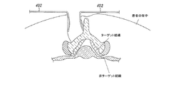
ここで図8Aから8Eを参照すると、代替的な実施例では、組織修正装置と、任意の1以上の導入/アクセス装置は、開腹手術の技術を用いて患者の体内に配置される。図8Aに示すように、例えば、一実施例では、開腹手術による切開部が患者の背中に作られ、2つの開創器402が、患者の椎骨の一部を露出するために使用される。次に、図8Bに示すように、導入シース414が、切開部を介して開創器402の間に挿入される。次に、図8Cに示すように、湾曲したガイド装置418が導入シース414を介して挿入される。ガイド装置418は、図8Dに示すように硬膜上腔に延在し、黄色靭帯の間を通る。   Referring now to FIGS. 8A-8E, in an alternative embodiment, the tissue modification device and any one or more introducer / access devices are placed in the patient's body using open surgical techniques. As shown in FIG. 8A, for example, in one embodiment, a laparotomy incision is made in the patient's back and two retractors 402 are used to expose a portion of the patient's vertebrae. Next, as shown in FIG. 8B, an introducer sheath 414 is inserted between the retractors 402 through the incision. Next, as shown in FIG. 8C, the curved guide device 418 is inserted through the introducer sheath 414. Guide device 418 extends into the epidural space as shown in FIG. 8D and passes between the ligamentum flavum.

いくつかの実施例では、湾曲したカニューレが挿入される薄い鋭利でないプローブが、開いた切開部を介して脊柱の硬膜上腔に配置され、代替的に、導入シース414を介して配置してもよい。プローブの先端部は、神経孔に又はこれを介して前進する。このようなプローブは、例えば、ウッドソンエレベータ(Woodson elevator)、ペンフィールド3(Penfield 3)、ホッケースティック状のプローブ、ボールが先端に付いたプローブ等と形状が似ている。代替的な実施例では、形状を変化させるために手動で曲げられるプローブ、関節の先端(articulating tip)を有するプローブ、形状固定部を有するプローブ、及び/又はカニューレの代わりに溝を有するプローブを用いてもよい。   In some embodiments, a thin sharp probe into which a curved cannula is inserted is placed in the epidural space of the spinal column through an open incision, and alternatively placed through an introducer sheath 414. Also good. The tip of the probe is advanced into or through the nerve hole. Such a probe is similar in shape to, for example, a Woodson elevator, a Penfield 3, a hockey stick probe, a probe with a ball attached to the tip, and the like. Alternative embodiments use a probe that is manually bent to change shape, a probe with an articulating tip, a probe with a shape anchor, and / or a probe with a groove instead of a cannula. May be.

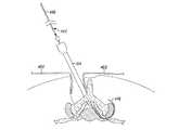
図8D及び8Eに示すように、鋭利な先端422を有するほぼ真っ直ぐな可撓性のあるガイドワイヤ420は、湾曲したガイド装置418を介して挿入されて前進し、鋭利な先端422を有するその遠位部が、開いた切開部とは異なる位置で患者の背中から出る(図8E)。次に、ガイド装置418が、図8Fに示すように取り出され、以降のステップでは、組織修正装置がガイドワイヤ420に沿って導入シース414内に導入され、以下にさらに詳細に説明するように組織を修正するのに用いられる。代替的な実施例では、湾曲した可撓性のあるカニューレが、神経孔の横に延在するまで、湾曲したガイド装置内に挿入され、この後、鋭利な先端を有するほぼ真っ直ぐで可撓性のあるガイドワイヤが、湾曲したカニューレ内に挿入されて前進し、鋭利な先端を有する遠位部が患者の背中から外側に延在する。   As shown in FIGS. 8D and 8E, a substantially straight flexible guidewire 420 having a sharp tip 422 is inserted and advanced through a curved guide device 418 and its distal end having a sharp tip 422. The position exits from the patient's back at a position different from the open incision (FIG. 8E). Next, the guide device 418 is removed as shown in FIG. 8F, and in subsequent steps, the tissue modification device is introduced along the guide wire 420 into the introducer sheath 414, as described in more detail below. Used to correct In an alternative embodiment, a curved flexible cannula is inserted into the curved guide device until it extends beside the nerve hole, after which it is substantially straight and flexible with a sharp tip. A guide wire is inserted into the curved cannula and advanced, with the distal portion having a sharp tip extending outward from the patient's back.

ここで図9A及び9Bを参照すると、別の代替的な開腹アクセス方法が示されている。図9Aでは、硬膜上腔と椎間孔を介して配置された湾曲したガイド装置446が示されており、勾配の付いた遠位先端442を有するガイドワイヤ440が、ガイド装置446を介して前進する。図9Bに示すように、この実施例では、ガイドワイヤ440は、様々なアクセス装置が導入される開いた切開部を通って、ガイド装置446により案内される。したがって、このような実施例では、一の切開部のみが形成され、1以上の装置の近位部及び遠位部が、患者の背中から同じ切開部を通って出る。   Referring now to FIGS. 9A and 9B, another alternative open access method is shown. In FIG. 9A, a curved guide device 446 disposed through the epidural space and intervertebral foramen is shown, and a guide wire 440 having a sloped distal tip 442 is routed through the guide device 446. Advance. As shown in FIG. 9B, in this embodiment, guidewire 440 is guided by guide device 446 through an open incision through which various access devices are introduced. Thus, in such an embodiment, only one incision is formed and the proximal and distal portions of one or more devices exit from the patient's back through the same incision.

様々な代替的な実施例では、開腹アクセスは、露出部を通って椎弓板に下がり、板層を除去していない黄色靭帯を通り、板層を部分的又は完全に除去した黄色靭帯を通り、中間の面関節を部分的又は完全に除去した板層を除去した又は除去していない黄色靭帯を通り、開いた露出部を通って横方向に皮膚を通り、開いた露出部を通って開いた露出部に戻り、又は側部から神経孔にアクセスする横方向の開いた露出部を通る。1以上の視覚化装置は、開腹アクセス処置と、経皮的又は非外傷的な処置で用いられる。別の代替的な実施例(図示せず)では、組織修正装置は、導入装置を用いずに患者に直接配置してもよい。   In various alternative embodiments, laparotomy access passes through the exposed portion to the lamina, through the yellow ligament where the lamina has not been removed, and through the yellow ligament where the lamina has been partially or completely removed. Through the yellow ligament with or without the plate layer with partial or complete removal of the intermediate facet joint, through the open exposed area, laterally through the skin, and open through the open exposed area Return to the exposed area or pass through the laterally open exposed area to access the nerve hole from the side. One or more visualization devices are used in open access procedures and percutaneous or atraumatic procedures. In another alternative embodiment (not shown), the tissue modification device may be placed directly on the patient without the introduction device.

ここで図10Aから10Eを参照すると、前述した実施例では、組織修正装置102,202が、少なくとも1の非組織修正(又は「保護」)部、側部、又は面を有している。非組織修正部分は、組織修正部材110,210がターゲット組織に面するときに非ターゲット組織の近くに配置されるように、組織修正装置101,202上に配置される。装置の非組織修正面は、組織を修正又は傷付けないように構成されており、これにより、非ターゲット組織は、組織を修正する処置の間に、好ましくない修正又は損傷から守られる。   Referring now to FIGS. 10A through 10E, in the embodiments described above, the tissue modification devices 102, 202 have at least one non-tissue modification (or “protect”) portion, side, or surface. The non-tissue modifying portion is disposed on the tissue modifying devices 101, 202 such that the tissue modifying members 110, 210 are disposed near the non-target tissue when facing the target tissue. The non-tissue modifying surface of the device is configured to not modify or damage the tissue, thereby protecting the non-target tissue from undesirable modification or damage during the tissue modifying procedure.

任意で、いくつかの実施例では、組織修正装置又はシステムはさらに、非ターゲット組織をさらに保護する1以上の組織保護部又はバリアを具えている。このような保護部は、組織修正装置に滑動可能に連結され、これに固定され、又は保護部を使用する装置から引き離される。様々な実施例では、保護部は、組織修正装置を送達する前にターゲット組織と非ターゲット組織との間に送達され、組織修正装置とともに送達され、又は組織修正装置の送達後であって装置が作動する前に送達される。一般に、保護部は非ターゲット組織と組織修正装置との間に配置される。   Optionally, in some embodiments, the tissue modification device or system further comprises one or more tissue protectors or barriers that further protect the non-target tissue. Such a protector is slidably connected to the tissue modifying device, secured thereto, or pulled away from the device using the protector. In various embodiments, the protector is delivered between the target tissue and the non-target tissue before delivering the tissue modifying device, delivered with the tissue modifying device, or after delivery of the tissue modifying device and the device is Delivered before operation. Generally, the protection unit is disposed between the non-target tissue and the tissue correction device.

図10Aは、導入装置514の遠位部を示しており、これを介して保護部が導入される。図10B及び10Cは、部分的に展開した保護装置500の一実施例とその断面をそれぞれ示している。通常、保護部500は、非ターゲット組織近くの領域に送達するための第1の小さな外形構成と、非ターゲット組織を保護するための拡張した構成とを具えている。保護部自体は、超弾性又は形状記憶素材の一部材として、骨組みの間を被う素材を有する骨組みとして、一連の拡張可能なワイヤ又はチューブとして、半円ののステント状装置として、1以上の膨張可能なバルーン又は袋として、ファン又はバネ荷重装置として、又は送達装置から解放されると拡張して組織を保護するように構成された様々な装置として構成してもよい。図10B及び10Cに示すように、保護部500は、導入装置514内の第2の端部502bに隣接する第1の端部502aに配置され、送達時に広がるシート素材を具えてもよい。代替的な実施例では、図10D及び10Eに示すように、保護装置520の単体の端部522a及び522bは、導入装置514内で重なる。一般に、一実施例では、保護部500,520は導入装置514を介して導入され、代替的に、図7Aから7S、8Aから8F、9A及び9Bに関連して説明した組織修正装置などの組織修正装置を導入するために、様々な手段を用いて導入してもよい。いくつかの実施例では、保護部500,520は、組織修正装置に固定し、又はこれの拡張部に固定してもよい。また、保護部500,520は、ガイドワイヤ又は他のガイド部材を通すために、様々な組織修正、薬物送達、若しくは診断装置を導入し、取り出し、若しくは交換するために、視覚化装置を通すために、組織修正部位の流体を洗浄するために、1以上のルーメン、レール、通路等を具えてもよい。いくつかの実施例では、保護部500,520が複数のガイドワイヤに沿って前進し、ガイドワイヤは、組織を修正する処置の間は配置されたままであり、保護部300,320を安定させ及び/又は位置を維持するのを促進する。   FIG. 10A shows the distal portion of the introducer 514 through which the protective portion is introduced. FIGS. 10B and 10C show an embodiment of a partially deployed protection device 500 and a cross section thereof, respectively. Typically, the protector 500 includes a first small profile configuration for delivery to an area near the non-target tissue and an expanded configuration for protecting the non-target tissue. The protector itself may be a superelastic or shape memory material, as a skeleton with a material covering between skeletons, as a series of expandable wires or tubes, as a semi-circular stent-like device, as one or more It may be configured as an inflatable balloon or bag, as a fan or spring loaded device, or as various devices configured to expand and protect tissue when released from the delivery device. As shown in FIGS. 10B and 10C, the protector 500 may comprise a sheet material that is disposed at the first end 502a adjacent to the second end 502b in the introducer 514 and that expands upon delivery. In an alternative embodiment, the single ends 522a and 522b of the protective device 520 overlap within the introducer 514, as shown in FIGS. 10D and 10E. In general, in one embodiment, the protectors 500, 520 are introduced via an introduction device 514, and alternatively, a tissue such as the tissue modification device described in connection with FIGS. 7A-7S, 8A-8F, 9A and 9B. In order to introduce the correction device, it may be introduced using various means. In some embodiments, the protectors 500, 520 may be secured to the tissue modification device or to an extension thereof. The protectors 500, 520 may also be used to pass visualization devices to introduce, remove or replace various tissue modification, drug delivery, or diagnostic devices for passing a guide wire or other guide member. In addition, one or more lumens, rails, passages, and the like may be provided to wash the fluid at the tissue modification site. In some embodiments, the protectors 500, 520 are advanced along a plurality of guidewires that remain in place during the tissue modification procedure to stabilize the protectors 300, 320 and Promote maintaining position.

ここで図11A及び11Bを参照すると、代替的な実施例では、電力式組織修正装置200が好適に、近位部2002を有する細長のシャフト2001と、遠位部2003及び長さ方向の軸2008と、シャフト2001の遠位部2003又はこれの近くに連結された1以上の組織修正部材2004と、シャフト2001の近位部2002又はこれの近くに連結されたハンドル2006とを具えている。任意で、いくつかの実施例は、装置2000を1以上の電源に接続する1以上の電源コネクタを具えてもよい。いくつかの実施例では、シャフト2001は、脊柱の硬膜上腔内で、黄色靭帯などのターゲット組織と神経及び神経血管組織などの非ターゲット組織との間に少なくとも遠位部2003を通すのを容易にする大きさ及び形状を有する。いくつかの実施例では、シャウト2001は、遠位部2003に又はこれの近くに1以上の屈曲部及び湾曲部を具え、装置2000の通過及び配置をさらに容易にしてもよい。いくつかの実施例では、例えば、屈曲部又は湾曲部により、遠位部2003の少なくとも一部を椎間孔に少なくとも部分的に通すのを容易にしてもよい。   Referring now to FIGS. 11A and 11B, in an alternative embodiment, the powered tissue modification device 200 is preferably an elongated shaft 2001 having a proximal portion 2002, a distal portion 2003 and a longitudinal axis 2008. And one or more tissue modifying members 2004 coupled to or near the distal portion 2003 of the shaft 2001 and a handle 2006 coupled to or near the proximal portion 2002 of the shaft 2001. Optionally, some embodiments may include one or more power connectors that connect device 2000 to one or more power sources. In some embodiments, the shaft 2001 allows at least the distal portion 2003 to pass between a target tissue such as the ligamentum flavum and a non-target tissue such as nerve and neurovascular tissue within the epidural space of the spinal column. Has a size and shape to facilitate. In some embodiments, the shout 2001 may include one or more bends and curves at or near the distal portion 2003 to further facilitate passage and placement of the device 2000. In some embodiments, at least a portion of the distal portion 2003 may be facilitated at least partially through the intervertebral foramen, for example, by a bend or bend.

いくつかの実施例では、図11Aに示すように、装置2000の遠位部2003が、棘突起近くの患者の背中の皮膚を介して前進する。次に、遠位部2003が、隣接する脊椎本体の薄板の間で硬膜上腔に前進し、ターゲット組織と非ターゲット組織の間に前進して、ターゲット組織を修正するために組織修正部材2004を所望の位置に配置する。次に、電力が供給されて組織修正部材2004が作動し、これによりターゲット組織を修正する。組織修正部材2004の近くの装置2000の一部は、非ターゲット組織に面するとともに、組織修正部材2004がターゲット組織に面するように構成されており、これにより、非ターゲット組織の好ましくない損傷又は修正を阻止する。いくつかの実施例では、前述したように、非ターゲット組織に面する装置の一部は、送達した物質により組織を保護し、及び/又は非ターゲット組織を検査してそれが非ターゲット組織であることを確認する等の方法で、非ターゲット組織を修正するように構成されている。   In some embodiments, as shown in FIG. 11A, the distal portion 2003 of the device 2000 is advanced through the skin on the patient's back near the spinous process. Next, the distal portion 2003 is advanced into the epidural space between adjacent vertebral body lamellas and advanced between the target and non-target tissues to modify the target tissue 2004 to modify the target tissue. Is placed in a desired position. Next, power is supplied to actuate the tissue modification member 2004, thereby modifying the target tissue. The portion of the device 2000 near the tissue modifying member 2004 is configured to face the non-target tissue and the tissue modifying member 2004 to face the target tissue, thereby causing undesirable damage or non-target tissue damage. Prevent modification. In some embodiments, as described above, the portion of the device that faces the non-target tissue protects the tissue with the delivered material and / or examines the non-target tissue and is non-target tissue The non-target organization is configured to be corrected by a method such as confirmation.

様々な実施例では、ハンドル2006は、好適な構成及び特徴を有している。いくつかの実施例では、ハンドル2006は、組織修正部材2004を作動させる1以上の作動部を具えている。電力コネクタ2010は、任意の好適な構成を有しており、電気、無線周波数、超音波、レーザ、又は伝導エネルギーなどの好適な種類のエネルギーを外部電源(図示せず)から様々な実施例の装置2000に送る。代替的な実施例では、装置2000は、バッテリーにより動作し、または他の好適な内部の電力又はパワーの供給源を使用し、このような内部のエネルギー供給源は、例えばハンドル2006内に収容される。通常、電力は供給源から組織修正部材2004に送られ、当該部材を作動させて組織を修正する。   In various embodiments, the handle 2006 has a suitable configuration and characteristics. In some embodiments, the handle 2006 includes one or more actuators that actuate the tissue modification member 2004. The power connector 2010 can have any suitable configuration, and can transmit a suitable type of energy, such as electricity, radio frequency, ultrasound, laser, or conduction energy, from various external power sources (not shown) in various embodiments. Send to device 2000. In alternative embodiments, the device 2000 is battery operated or uses other suitable internal power or power sources, such internal energy sources housed within the handle 2006, for example. The Typically, power is sent from the source to the tissue modification member 2004, which is actuated to modify the tissue.

ここで図11Bを参照すると、様々な実施例では、組織修正装置2000が、一部が既に説明された様々な好適な技術及び手段を用いて患者の体内に前進する。図11Aは、反対側の手段からターゲット組織と非ターゲット組織との間の位置に装置2000の遠位部2003を前進させる一の手段を示しており、図11Bは、同じ側の手段を示している。図11Bに示すように、遠位部2003は、2以上の湾曲部を有しており、及び/又は様々な実施例に係る所望の接近角度を容易にする少なくとも部分的に可撓性又は可動性を有する。   Referring now to FIG. 11B, in various embodiments, the tissue modification device 2000 is advanced into the patient's body using various suitable techniques and means, some of which have already been described. FIG. 11A shows one means for advancing the distal portion 2003 of the device 2000 from the opposite means to a position between the target tissue and the non-target tissue, and FIG. 11B shows the means on the same side. Yes. As shown in FIG. 11B, the distal portion 2003 has two or more curved portions and / or is at least partially flexible or movable to facilitate a desired approach angle according to various embodiments. Have sex.

図12を参照すると、別の実施例では、組織修正装置2020は、近位部2012及び遠位部2013を有する細長のシャフト2011と、1以上の組織修正部材2014と、シャフト2011に連結された伝導電極2015と、ハンドル2016と、電力コネクタ2030と、複数の追加の接続部材2032,2033とを具えている。電極2015は、非ターゲットの周波数と非ターゲットの電流の振幅を非ターゲット組織に送るように構成されている。非ターゲットの周波数及び非ターゲットの振幅は、神経組織からの反応を刺激する。一実施例では、第1の接続部材2032は、電力を電極2015に供給し、非ターゲット組織が電極からの電流により刺激される場合、EMG、SSEP又は筋肉の動作を観察することにより分かるこの刺激の観測により、電極2015が非ターゲット組織の近くにあることを照明する。また、ターゲットを刺激する電流は、第2の接続部材2033を介して組織修正部材2014(例えば、電気伝導性のある素材で構成される)に、及び/又は組織修正部材2014のような同じ側の装置2020の近く且つこれに配置されたターゲット刺激電極に送られる。例えば、ターゲットを刺激する電流が、神経組織からの反応を刺激する周波数及び振幅で構成されている場合、組織修正部材2014の直ぐ近くの組織の種類は(例えば、神経、又は神経でない)、組織の反応の有無に基づいて判断する。一実施例では、装置2020は、ターゲットを刺激する電流と非ターゲットを刺激する電流の制御を可能にするよう構成されている。例えば、ターゲットを刺激する電流と非ターゲットを刺激する電流は、装置2020の遠位部2013に順に送られ、組織修正部材が作動する前に神経組織の位置を判断し、例えば、組織修正部材2014が確実に神経組織を傷付けないようにする。   Referring to FIG. 12, in another embodiment, a tissue modification device 2020 is coupled to an elongate shaft 2011 having a proximal portion 2012 and a distal portion 2013, one or more tissue modification members 2014, and the shaft 2011. A conductive electrode 2015, a handle 2016, a power connector 2030, and a plurality of additional connecting members 2032 and 2033 are provided. Electrode 2015 is configured to send non-target frequencies and non-target current amplitudes to non-target tissue. Non-target frequencies and non-target amplitudes stimulate responses from neural tissue. In one example, the first connecting member 2032 provides power to the electrode 2015, and this stimulation as seen by observing EMG, SSEP or muscle movement when non-target tissue is stimulated by current from the electrode. Illuminates that the electrode 2015 is near the non-target tissue. Further, the current that stimulates the target is supplied to the tissue correction member 2014 (for example, made of an electrically conductive material) via the second connection member 2033 and / or the same side as the tissue correction member 2014. To a target stimulation electrode located near and on the device 2020. For example, if the current that stimulates the target is configured with a frequency and amplitude that stimulates a response from neural tissue, the tissue type immediately adjacent to the tissue modification member 2014 (eg, nerve or not nerve) Judgment based on the presence or absence of reaction. In one embodiment, device 2020 is configured to allow control of currents that stimulate targets and currents that stimulate non-targets. For example, currents that stimulate the target and currents that stimulate the non-target are sequentially sent to the distal portion 2013 of the device 2020 to determine the position of the neural tissue before the tissue correction member is activated, for example, the tissue correction member 2014. Ensure that the nerve tissue is not damaged.

様々な実施例では、組織修正部材2014は、1以上のロンジュール、キューレット、メス、1以上の切断ブレード、ハサミ、鉗子、プローブ、鬼目やすり、やすり、研磨部材、1以上の小さな面、電気外科手術装置、双極電極、単極電極、熱電極、回転式電力機構シェーバ、往復式電力機構シェーバ、電力機構ばり、レーザ、超音波水晶、低温プローブ、加圧されるウォータジェット、投薬部材、針、針電極、またはこれらの組み合わせのうちの少なくとも一つを具えてもよい。いくつかの実施例は、一の組織修正部材2014を具えており、他の実施例は複数の組織修正部材2014を具えている。以下にさらに説明するように、組織修正部材2014は、様々な好適な大きさ、形状及び構成を具えており、任意の好適な方法で移動又は動作してもよい。   In various embodiments, the tissue modification member 2014 includes one or more long joules, curettes, scalpels, one or more cutting blades, scissors, forceps, probes, demon files, files, abrasive members, one or more small surfaces, Electrosurgical device, bipolar electrode, monopolar electrode, thermal electrode, rotary power mechanism shaver, reciprocating power mechanism shaver, power mechanism flash, laser, ultrasonic crystal, cryogenic probe, pressurized water jet, dosing member, It may comprise at least one of a needle, a needle electrode, or a combination thereof. Some embodiments include one tissue modification member 2014, and other embodiments include a plurality of tissue modification members 2014. As described further below, the tissue modification member 2014 has a variety of suitable sizes, shapes and configurations and may move or operate in any suitable manner.

ここで図13Aを参照すると、代替的な実施例では、組織修正装置2040が、細長のシャフト2041と、1以上の組織修正部材2044と、ハンドル2046と、電力コネクタ2050とを具えている。さらに、装置2040は、シャフト2041の全部又は一部を通って延在するガイドワイヤルーメン(図示せず)を具え、近位端2049及び遠位端2047を有するガイドワイヤ2048がこれを通過するのを可能にする。一実施例では、例えば、ガイドワイヤ2048は、シャフト2041の近位端からシャフト2041の遠位端を通って延在して患者の体外に出る。いくつかの実施例では、前述したように、固定力及び/又は張力を遠位端2047及び/又は近位端2049に又はこれの近くに加えて、組織修正部材2044をターゲット組織に対して移動させてもよい。   Referring now to FIG. 13A, in an alternative embodiment, a tissue modification device 2040 includes an elongate shaft 2041, one or more tissue modification members 2044, a handle 2046, and a power connector 2050. In addition, the device 2040 includes a guidewire lumen (not shown) extending through all or part of the shaft 2041, through which a guidewire 2048 having a proximal end 2049 and a distal end 2047 passes. Enable. In one example, for example, guidewire 2048 extends from the proximal end of shaft 2041 through the distal end of shaft 2041 and out of the patient's body. In some embodiments, as described above, fixation force and / or tension is applied to or near the distal end 2047 and / or proximal end 2049 to move the tissue modification member 2044 relative to the target tissue. You may let them.

図13Aに示す実施例では、比較的平らな構成を有する組織修正部材2044が示されている。ここで説明する多くの二次的な実施例では、組織修正部材の様々な実施例が、主に説明を容易にするために平らな構成を有するように示されている。しかしながら、代替的な実施例では、及び図13Bを参照すると、組織修正装置は、ターゲット組織に接触する湾曲した/可撓性のある表面を有する湾曲した及び/又は可撓性のある組織修正部材2045(又は複数の湾曲した及び/又は可撓性のある部材)を具えている。また、装置2040は、湾曲した及び/又は可撓性のあるシャフト2042を具えてもよい。いくつかの実施例では、このような湾曲した及び/又は可撓性のある組織修正部材2045(又は組織修正表面)及びシャフト2042が組織の修正を容易にし、組織修正部材2045は、ターゲット組織の確認をさらに容易にする。代替的な実施例では、全部ではないが本出願で説明した装置の多くが、このような湾曲した及び/又は可撓性のある組織修正部材を有してもよい。   In the embodiment shown in FIG. 13A, a tissue modifying member 2044 having a relatively flat configuration is shown. In many of the secondary embodiments described herein, various embodiments of tissue modifying members are shown having a flat configuration, primarily for ease of explanation. However, in an alternative embodiment, and with reference to FIG. 13B, the tissue modification device includes a curved and / or flexible tissue modification member having a curved / flexible surface that contacts the target tissue. 2045 (or a plurality of curved and / or flexible members). The device 2040 may also include a curved and / or flexible shaft 2042. In some embodiments, such a curved and / or flexible tissue modifying member 2045 (or tissue modifying surface) and shaft 2042 facilitate tissue modification, and the tissue modifying member 2045 can be Make verification even easier. In alternative embodiments, many but not all of the devices described in this application may have such curved and / or flexible tissue modifying members.

ここで図13Cから13Eを参照すると、組織修正装置とともに使用する固定部材のいくつかの代替的な実施例が示されている。図13Cは、例えば、ガイドワイヤ2048に連結されたワイヤアンカ2060を具える組織修正装置2040を示している。様々な実施例では、ワイヤアンカ2060は、ガイドワイヤ2048の遠位端2047に又はこれの近くに取り外し可能に取り付けられ又は固定され、患者の体外から患者の背中に対して固定力を供給する。ワイヤアンカ2060は、ガイドワイヤ2048が患者の背中から近位端2049に向かって移動するのを最小限にし又は阻止する。代替的な実施例では、追加的な固定力及び/又は張力が、手で遠位端2047を把持し及び/又は引っ張ることにより遠位端2047に供給される。   Referring now to FIGS. 13C through 13E, several alternative embodiments of a fixation member for use with a tissue modification device are shown. FIG. 13C shows a tissue modification device 2040 comprising, for example, a wire anchor 2060 coupled to a guidewire 2048. FIG. In various embodiments, the wire anchor 2060 is removably attached or secured to or near the distal end 2047 of the guidewire 2048 to provide a securing force against the patient's back from outside the patient's body. Wire anchor 2060 minimizes or prevents guide wire 2048 from moving from the patient's back toward proximal end 2049. In an alternative embodiment, additional securing force and / or tension is supplied to the distal end 2047 by grasping and / or pulling the distal end 2047 by hand.

代替的な実施例では、図13Dに示すように、ガイドワイヤ2048の遠位端2047は、1以上の展開可能な固定部材2062を有しており、これは、患者の体内で展開し、筋肉、骨、靭帯などの患者の背中の組織を固定する。一実施例では、例えば、ガイドワイヤ2048は、1以上のルーメン(図示せず)を具えてもよく、固定部材2062は、ルーメン内を移動して遠位端2047から延在する。組織を修正する処置が完了すると、固定部材2062がルーメン内に引っ込み、ガイドワイヤ2048が患者からさらに容易に取り外される。   In an alternative embodiment, as shown in FIG. 13D, the distal end 2047 of the guidewire 2048 has one or more deployable fixation members 2062, which are deployed in the patient's body and are muscular. Fix the patient's back tissue, such as bones, ligaments. In one example, for example, the guidewire 2048 may include one or more lumens (not shown), and the fixation member 2062 moves within the lumen and extends from the distal end 2047. When the tissue modification procedure is complete, the fixation member 2062 retracts into the lumen and the guidewire 2048 is more easily removed from the patient.

図13Eを参照すると、別の実施例では、組織除去装置2040が、1以上の近位のシャフト固定部材2066及び/又は1以上の近位のガイドワイヤ固定部材2064を具えている。代替的な実施例では、シャフト固定部材2066は、シャフト2041に連結され、又はこれに取り外し可能に連結され、固定力を加えるのを容易にしてもよい。例えば、一実施例では、シャフト固定部材2066は、患者の背中に接触して、シャフト2041が患者の体内に移動するのを阻止する。   Referring to FIG. 13E, in another embodiment, the tissue removal device 2040 includes one or more proximal shaft fixation members 2066 and / or one or more proximal guidewire fixation members 2064. In an alternative embodiment, the shaft securing member 2066 may be coupled to or removably coupled to the shaft 2041 to facilitate applying a securing force. For example, in one embodiment, shaft fixation member 2066 contacts the patient's back and prevents shaft 2041 from moving into the patient's body.

近位のガイドワイヤ固定部材2064は、図示するようにハンドル2046内に設けてもよく、他の実施例では、ハンドル2046の近く又は遠くに配置してもよい。ガイドワイヤ固定部材2064を用いてガイドワイヤ2048をロック又は固定し、ガイドワイヤが装置2040の内側又は外側に移動するのを阻止し、又は最小限にする。これにより、ガイドワイヤ2048を介して張力及び/又は固定力を加えるのが容易になる。   Proximal guidewire securing member 2064 may be provided in handle 2046 as shown, and in other embodiments may be located near or far from handle 2046. A guide wire securing member 2064 is used to lock or secure the guide wire 2048 to prevent or minimize the guide wire from moving in or out of the device 2040. This facilitates the application of tension and / or fixing force via the guidewire 2048.

図13F及び13Gは、図13の線C−Cのハンドル2046及び近位のガイドワイヤ固定部材2064の断面図を示している。一実施例では、ハンドル2046は、近位のガイドワイヤ固定部材2064と、第1のルーメン内の組織修正ドライブ2068と、ガイドワイヤルーメン2070内のガイドワイヤ2048と、対応するガイドタブ2075を有する複数のガイドスロット2074と、1以上のローブとを具えている。図13Fに示すように、ガイドワイヤ固定部材2064が係合していない場合、ローブ2072が邪魔しないため、ガイドワイヤ2048は、ガイドワイヤルーメン2070内を自由に移動する。図13Gに示すように、例えば、ガイドワイヤ固定部材2064をハンドル2046に対して移動させ及び/又は回転させることにより、ガイドワイヤ固定部材2064が係合している場合、ガイドワイヤ2048は、ローブ2072のガイドワイヤ固定部材2064とガイドワイヤルーメン2070の壁との間で摩擦により合致する(例えば、締め付け、はさむ)。次に、ガイドワイヤ固定部材2064が元の位置に移動及び/又は回転し(図13F)、ガイドワイヤ2048が解放される。   13F and 13G show cross-sectional views of the handle 2046 and proximal guidewire anchoring member 2064 of line CC in FIG. In one example, the handle 2046 includes a plurality of proximal guidewire securing members 2064, a tissue modification drive 2068 in the first lumen, a guidewire 2048 in the guidewire lumen 2070, and a corresponding guide tab 2075. Guide slot 2074 and one or more lobes. As shown in FIG. 13F, when the guide wire fixing member 2064 is not engaged, the lobe 2072 does not interfere, so the guide wire 2048 moves freely in the guide wire lumen 2070. As shown in FIG. 13G, when the guidewire securing member 2064 is engaged, for example, by moving and / or rotating the guidewire securing member 2064 relative to the handle 2046, the guidewire 2048 is in the lobe 2072. Between the guide wire fixing member 2064 and the wall of the guide wire lumen 2070 by friction (for example, tightening and pinching). Next, the guide wire fixing member 2064 moves and / or rotates to the original position (FIG. 13F), and the guide wire 2048 is released.

ここで図14を参照すると、いくつかの実施例では、組織除去装置2100が、近位部2106及び遠位部2105を具える細長のシャフト2104と、1以上の組織修正部材2108と、近位部2106に連結された移動可能なハンドル2103と、電力コネクタ2107とを具えている。図示する実施例では、遠位部2105は少なくとも部分的に操縦可能であり(図14では2つの重なる遠位部として示されている)、移動可能なハンドル2103を用いて(両方向の真っ直ぐな矢印)、遠位部2105を操縦するとともに、シャフト2104を相対的に安定した状態で保持する。操縦可能な遠位部2105は、ターゲット組織に接触し、これに対して力を加える組織修正部材2108の能力を強化する。いくつかの実施例では、組織修正部材2108の配置は、シャフト2104を有意に移動させることなく、操縦可能な遠位部2105を用いて調整される。いくつかの実施例では、操縦可能な遠位部2105は、シャフト2104に対して横方向、上下方向になど、複数の方向に移動してもよい。一実施例では、移動可能なハンドル2103は、ピストン運動により動作し、ハンドル2102の遠位部がシャフトに取り付けられ、近位部のハンドル2103が張力部材に取り付けられる。張力部材は、ハンドル2103が作動するときに、操縦可能な遠位端2105に張力を伝え、遠位端2105を偏向させる。様々な実施例では、本技術分野で周知の他のハンドル操縦機構及び/又は他の操縦機構を用いてもよい。   Referring now to FIG. 14, in some embodiments, a tissue removal device 2100 includes an elongate shaft 2104 comprising a proximal portion 2106 and a distal portion 2105, one or more tissue modifying members 2108, a proximal portion A movable handle 2103 connected to the portion 2106 and a power connector 2107 are provided. In the illustrated embodiment, the distal portion 2105 is at least partially steerable (shown as two overlapping distal portions in FIG. 14) and uses a movable handle 2103 (a straight arrow in both directions). ), Steer the distal portion 2105 and hold the shaft 2104 relatively stable. The steerable distal portion 2105 enhances the ability of the tissue modification member 2108 to contact and apply force to the target tissue. In some embodiments, the placement of the tissue modifying member 2108 is adjusted using the steerable distal portion 2105 without significantly moving the shaft 2104. In some embodiments, the steerable distal portion 2105 may move in a plurality of directions, such as laterally relative to the shaft 2104, up and down. In one embodiment, the movable handle 2103 operates by piston motion, with the distal portion of the handle 2102 attached to the shaft and the proximal handle 2103 attached to the tension member. The tension member transmits tension to the steerable distal end 2105 and deflects the distal end 2105 when the handle 2103 is actuated. In various embodiments, other handle steering mechanisms and / or other steering mechanisms known in the art may be used.

図15A及び15Bは、組織修正装置2080の一実施例を示しており、これは、細長のシャフト2081と、1以上の組織修正部材2082と、ハンドル2084と、視覚化装置2086と、光ケーブル2090と、電力コネクタ2088とを具えている。視覚化装置2086は、エンドスコープなどの任意に好適な装置を具えてもよいが、これに限られない。エンドスコープ視覚化装置は、例えば、光(又は他のエネルギー)を送達して組織を照射して画像を取得するために、レンズ及び/又は光ファイバを具えてもよい。図15Bに示すように、いくつかの実施例では、視覚化装置2086は、1以上の画像取得部材2094と、1以上の照射部材2092とを具えている。いくつかの実施例では、画像取得部材2094は、例えばCCD又はCMOSチップを具えている。照射部材2092には、例えば、1以上の発光ダイオード(LED)又は光ファイバが含まれる。   FIGS. 15A and 15B show one embodiment of a tissue modification device 2080 that includes an elongated shaft 2081, one or more tissue modification members 2082, a handle 2084, a visualization device 2086, and an optical cable 2090. And a power connector 2088. The visualization device 2086 may comprise any suitable device such as, but not limited to, an endoscope. The endoscope visualization device may comprise a lens and / or optical fiber, for example, to deliver light (or other energy) to illuminate the tissue and acquire an image. As shown in FIG. 15B, in some embodiments, the visualization device 2086 includes one or more image acquisition members 2094 and one or more illumination members 2092. In some embodiments, the image acquisition member 2094 comprises a CCD or CMOS chip, for example. The irradiation member 2092 includes, for example, one or more light emitting diodes (LEDs) or optical fibers.

いくつかの実施例では、光ケーブル2090が光ファイバを具えている。光ファイバの一部又は総ては、照射部材2092を具えており、又はこれに連結される。代替的又は付加的に、光ファイバの一部又は総てをカメラ(図示せず)に接続してもよい。例えば、このようなカメラは、組織修正装置2080の近位端に取り付けられる。代替的に、光ケーブル2090は、電源(例えば、出力LED)及び/又は画像取得部材2094に接続された1以上の電気ワイヤを具えてもよい。様々な実施例では、レンズ、光ファイバ、LED、又はこれらの組み合わせは、画像を取得するために使用されるレンズ、光ファイバ、CCD、CMOS、又はこれらの組み合わせとともに、照射のために利用してもよい。   In some embodiments, the optical cable 2090 comprises an optical fiber. Part or all of the optical fiber includes or is connected to the illumination member 2092. Alternatively or additionally, some or all of the optical fiber may be connected to a camera (not shown). For example, such a camera is attached to the proximal end of the tissue modification device 2080. Alternatively, the optical cable 2090 may comprise a power source (eg, an output LED) and / or one or more electrical wires connected to the image acquisition member 2094. In various embodiments, a lens, fiber optic, LED, or combination thereof may be utilized for illumination along with a lens, fiber optic, CCD, CMOS, or combination thereof used to acquire an image. Also good.

ここで図16を参照すると、組織修正装置2120別の実施例が、好適には細長のシャフト2132と、1以上の組織修正部材2130と、ハンドル2124と、視覚化装置2122と、光ケーブル2128と、電力コネクタ2126とを具えている。この実施例では、視覚化装置2122は、シャフト2132上の組織修正部材2130の近くに配置される。様々な実施例では、視覚化装置2112をシャフト2132に沿って所望の位置に配置してもよい。   Referring now to FIG. 16, another embodiment of the tissue modification device 2120 is preferably an elongated shaft 2132, one or more tissue modification members 2130, a handle 2124, a visualization device 2122, an optical cable 2128, And a power connector 2126. In this example, the visualization device 2122 is positioned near the tissue modifying member 2130 on the shaft 2132. In various embodiments, the visualization device 2112 may be positioned along the shaft 2132 at a desired location.

図17Aから17Eは、図16の線A−Aのシャフト2132の様々な実施例の断面図を示している。図17Aに示す実施例では、例えば、シャフト2132は、組織修正ドライブルーメン2140内の組織修正ドライブ2134と、ガイドワイヤルーメン2138内のガイドワイヤ2136とを具えている。組織修正ドライブ2134は、組織修正ドライブルーメン2140に対して移動又は回転するように構成してもよい。組織修正ドライブ2134の例には、ドライブシャフト、1以上の導電ワイヤ、1以上の光ファイバ等が含まれるが、これらに限定されない。また、様々な実施例は、装置のハンドル内に、装置の遠位端近くに、個別のドライブ装置内等に配置されるモータを具えている。   17A through 17E show cross-sectional views of various embodiments of the shaft 2132 taken along line AA in FIG. In the embodiment shown in FIG. 17A, for example, the shaft 2132 includes a tissue modification drive 2134 in the tissue modification drive lumen 2140 and a guidewire 2136 in the guidewire lumen 2138. The tissue modification drive 2134 may be configured to move or rotate relative to the tissue modification drive lumen 2140. Examples of tissue modification drive 2134 include, but are not limited to, a drive shaft, one or more conductive wires, one or more optical fibers, and the like. Various embodiments also include a motor disposed in the handle of the device, near the distal end of the device, such as in a separate drive device.

代替的な実施例では、図17Bに示すように、シャフト2132が、組織修正ドライブルーメン2140内の組織修正ドライブ2134と、ガイドワイヤルーメン2138内のガイドワイヤ2136と、視覚化ルーメン2144内の伝導部材2146と、吸引/洗浄ルーメン2142とを具えている。吸引/洗浄ルーメン2142は、例えば、患者の体外から装置の遠位端に気体、流体又は押すことできる固体(例えば、粒状固体)を送達し、又はターゲット組織の領域から患者の体外に、気体、流体、組織及び/又は他の物質を吸引するために使用される。いくつかの実施例では、吸引/洗浄ルーメン2142を用いて、長くて可撓性のある針又は生検鉗子などの器具を滑動可能に通過させる。いくつかの実施例では、視覚化ルーメン2144は、装置の遠位端でLEDに電力を供給する部材などの伝導部材2146を受けるように構成し、及び/又は視覚的な画像を取得し、それを電気信号に変換する装置の遠位端に配置されたCCD又はCMOSチップからの信号を患者の体外に設定されたディスプレイに送るように構成してもよい。   In an alternative embodiment, as shown in FIG. 17B, shaft 2132 includes tissue modification drive 2134 in tissue modification drive lumen 2140, guide wire 2136 in guidewire lumen 2138, and conductive member in visualization lumen 2144. 2146 and a suction / cleaning lumen 2142. The aspiration / wash lumen 2142 delivers, for example, a gas, fluid or pushable solid (eg, a particulate solid) from outside the patient's body to the distal end of the device, or from the target tissue region outside the patient's body, Used to aspirate fluid, tissue and / or other substances. In some embodiments, the suction / wash lumen 2142 is used to slidably pass instruments such as long and flexible needles or biopsy forceps. In some embodiments, the visualization lumen 2144 is configured to receive a conducting member 2146, such as a member that provides power to the LED at the distal end of the device, and / or obtains a visual image, May be configured to send a signal from a CCD or CMOS chip located at the distal end of the device that converts the signal to an electrical signal to a display set outside the patient's body.

さらに別の代替的な実施例では、図17Cに示すように、シャフト2132が、組織修正ドライブルーメン2140内の組織修正ドライブ2134と、視覚化ルーメン2144内の伝導部材及び/又は光ファイバ2152と、個別の吸引ルーメン2150及び洗浄ルーメン2148とを具えている。いくつかの実施例では、吸引ルーメン2150及び洗浄ルーメン2148を利用して、気体、流体、及び/又は押すことができる固体を、組織修正装置の遠位端に及びこれから同時に又は連続して送達及び除去する。気体、流体、及び/又は押すことが可能な固体の送達及び除去により、分離した及び/又は分離していないターゲット組織と治療部位の他の破片を洗浄し、及び/又は視覚化部材によりターゲット及び非ターゲット組織の明瞭な視覚化を維持する。   In yet another alternative embodiment, as shown in FIG. 17C, shaft 2132 includes tissue modification drive 2134 in tissue modification drive lumen 2140, conductive member and / or optical fiber 2152 in visualization lumen 2144, A separate suction lumen 2150 and a cleaning lumen 2148 are provided. In some embodiments, the suction lumen 2150 and the irrigation lumen 2148 are used to deliver gas, fluid, and / or pushable solids to and from the distal end of the tissue modification device and simultaneously or sequentially. Remove. The separated and / or unseparated target tissue and other debris of the treatment site are cleaned by delivery and removal of gas, fluid, and / or pushable solids, and / or the target and Maintain a clear visualization of non-target tissues.

別の実施例では、図17Dに示すように、光ファイバ2152は、中空のシャフト2132内の様々なルーメン2148,2150,2144,2140の間に配置される。代替的に、他の実施例では、光ファイバ2152は電気コンダクタと交換してもよい。光ファイバ2152は、光を送ってターゲット組織を照射し、及び/又は組織からの光を表示装置に送る。このような実施例では、視覚化ルーメン2144は、光又は電気信号を近位方法及び/又は遠位方向に送る。   In another embodiment, as shown in FIG. 17D, the optical fiber 2152 is disposed between the various lumens 2148, 2150, 2144, 2140 within the hollow shaft 2132. Alternatively, in other embodiments, the optical fiber 2152 may be replaced with an electrical conductor. The optical fiber 2152 sends light to illuminate the target tissue and / or sends light from the tissue to the display device. In such an embodiment, the visualization lumen 2144 sends light or electrical signals in the proximal method and / or distal direction.

さらに別の代替的な実施例では、図17Eに示すように、シャウト2132が、操縦ルーメン2156内に操縦作動部2154を具えている。操縦作動部2154を用いて、例えば、以下にさらに説明するように組織修正装置の遠位部を操縦する。   In yet another alternative embodiment, as shown in FIG. 17E, a shout 2132 includes a steering actuator 2154 within the steering lumen 2156. Steering actuator 2154 is used to steer the distal portion of the tissue modification device, for example, as further described below.

図18は、線B−Bの図16の組織修正装置2120の端部の断面図である。この実施例では、視覚化装置2122及び照射部材2158は、組織修正部材2130の近くに配置される。図示する実施例では、組織修正部材2130は、ベアリング2160のポストに設けられた回転ディスクと、このディスク上の複数の隆起した切断エッジ2131を具えている。2つの吸引/洗浄ルーメン2142により、組織修正領域から気体、流体、及び/又は押すことが可能な固体の導入及び吸引が可能となる。   18 is a cross-sectional view of the end of the tissue modification device 2120 of FIG. 16 taken along line BB. In this example, the visualization device 2122 and the illumination member 2158 are positioned proximate to the tissue modification member 2130. In the illustrated embodiment, the tissue modifying member 2130 comprises a rotating disk provided on the post of the bearing 2160 and a plurality of raised cutting edges 2131 on the disk. Two suction / cleaning lumens 2142 allow for the introduction and suction of gases, fluids, and / or pushable solids from the tissue modification region.

図19Aから23Bは、様々な組織修正部材を有する組織修正装置の遠位端の多くの実施例を示している。これらの実施例では、装置は、ガイドワイヤにより遠位に連結でき、または図示する組織修正部分から遠位方向に延在し、装置が遠位方向に患者から延在する。図19Aから19Cを参照すると、別の実施例では、組織修正装置2310は、遠位開口2316から延在するドライブシャフト2314に連結され、研磨面を有する移動可能なプラットホームを具える組織修正部材2312を具えている。様々な図に示すように、いくつかの実施例では、組織修正部材2312は、横方向に移動し(図19A)、前後に移動し(図19B)、及び/又は振動する(図19C)。   Figures 19A through 23B show many examples of the distal end of a tissue modification device having various tissue modification members. In these examples, the device can be connected distally by a guidewire or extends distally from the tissue modification portion shown, and the device extends distally from the patient. Referring to FIGS. 19A-19C, in another embodiment, a tissue modification device 2310 is coupled to a drive shaft 2314 extending from a distal opening 2316 and includes a tissue modification member 2312 comprising a movable platform having an abrasive surface. It has. As shown in the various figures, in some embodiments, the tissue modifying member 2312 moves laterally (FIG. 19A), moves back and forth (FIG. 19B), and / or vibrates (FIG. 19C).

さらに別の実施例では、図20に示すように、組織修正装置2320が、遠位開口2326から延在するドライブシャフト2324に連結され、研磨面を有する卵形又は円形のプラットホームを具えた組織修正部材2322を具えている。このような実施例では、組織修正部材2322は、様々な実施例により、円を描くように回転又は移動し、また、移動し、横方向に移動し、往復し、及び/又は振動する。   In yet another embodiment, as shown in FIG. 20, a tissue modification device 2320 is coupled to a drive shaft 2324 extending from a distal opening 2326 and comprises a tissue modification comprising an oval or circular platform having an abrasive surface. A member 2322 is provided. In such embodiments, the tissue modifying member 2322 rotates or moves in a circular fashion, and moves, moves laterally, reciprocates, and / or vibrates according to various embodiments.

図21を参照すると、別の実施例では、組織修正装置2330が複数の組織修正部材2332を具えており、それぞれが、ドライブシャフト2334に取り付けられた研磨面を有する移動可能なプラットホーム2333を具えている。組織修正部材は、好適なパターンで互いに及びデバイスシャフトに対して前後に移動する。組織修正部材2332が互いに前後に移動することにより、ターゲット組織に張力を加えるのを促進し、これにより、組織修正部材2332が、ターゲット組織を切断し、せん断し、引き裂き、及び/又は修正する能力を強化する。   Referring to FIG. 21, in another embodiment, tissue modification device 2330 includes a plurality of tissue modification members 2332, each including a movable platform 2333 having an abrasive surface attached to drive shaft 2334. Yes. The tissue modifying members move back and forth relative to each other and the device shaft in a suitable pattern. The ability of tissue modifying members 2332 to move back and forth relative to each other facilitates tensioning the target tissue so that tissue modifying member 2332 can cut, shear, tear and / or modify the target tissue. To strengthen.

図22に示すように、別の代替的な実施例では、組織修正装置2340が好適には、それぞれが切断エッジ2345a,2345bを有する遠位ブレード2344a及び近位ブレード2344bなどの1以上のブレードを有する組織修正部材を具える。図示する実施例では、近位ブレード2344bは移動可能であり、対向する遠位ブレード2344aにに向かって遠位方向に移動する。代替的な実施例では、遠位ブレード2344aが移動可能でもよく、又は双方のブレード2344a,2344bが移動可能でもよい。代替的な実施例は、1の移動可能なブレード、一方向に接触する2以上の移動可能なブレード、様々な方向で接触する2以上のブレード、移動可能なブレード及び当該ブレードが突き当たるバックストップ、又は移動可能及び/又は固定されたブレードの他の好適な組み合わせを具えてもよい。さらに、所定の実施例のブレードは、好適な形状、大きさ、及び全体構成を具えてもよい。いくつかの実施例では、ブレードは平らでもよく、他の実施例では、湾曲、四角、波状、屈曲、鋸歯状等でもよい。ブレードは、長くても短くてもよく、複数のブレードは、髭を剃るのに使用される通常の複数のブレードのかみそりのように互いに隣接して配置してもよく、複数のブレードは、数ミリ又は数センチ等互いに離してもよい。ブレードは、好適な程度の鋭利さ又は鈍感さを有してもよく、いくつかの実施例では、鋭利なブレードと鈍感なブレードの組み合わせを用いてもよい。したがって、ブレードの例示的な実施例が前述され、又は以下に説明されているが、他の好適なブレード又はブレードの組み合わせは、本発明の範囲から逸脱することなく、様々な実施例において置換される。   As shown in FIG. 22, in another alternative embodiment, the tissue modification device 2340 preferably includes one or more blades, such as a distal blade 2344a and a proximal blade 2344b, each having a cutting edge 2345a, 2345b. Having a tissue modifying member. In the illustrated embodiment, the proximal blade 2344b is movable and moves distally toward the opposing distal blade 2344a. In alternative embodiments, the distal blade 2344a may be movable, or both blades 2344a, 2344b may be movable. Alternative embodiments include one movable blade, two or more movable blades that contact in one direction, two or more blades that contact in various directions, a movable blade, and a backstop against which the blade abuts, Alternatively, other suitable combinations of movable and / or fixed blades may be provided. Further, the blades of certain embodiments may have any suitable shape, size, and overall configuration. In some embodiments, the blade may be flat, and in other embodiments may be curved, square, wavy, bent, serrated, etc. The blades may be long or short, and the multiple blades may be placed adjacent to each other, like a normal multiple blade razor used to shave a razor. They may be separated from each other by millimeters or several centimeters. The blade may have a suitable degree of sharpness or insensitivity, and in some embodiments, a combination of sharp and insensitive blades may be used. Thus, although exemplary embodiments of blades are described above or described below, other suitable blades or combinations of blades may be substituted in various embodiments without departing from the scope of the present invention. The

ここで代替的な実施例に示したブレード2344a,2344b又は他のブレードは、金属、ポリマー、セラミック、他の好適な素材、又は素材の組み合わせから作ってもよい。様々な実施例では、ブレードに好適な素材は、ステンレス鋼(303,304,316,316L)、ニッケルチタニウム合金、又はコバルトクロミウム合金、例えば、Elgiloy(登録商標)(米国イリノイ州エルジン所在のElgin Specially Metals)、Conichrome(登録商標)(米国ペンシルバニア州リーディング所在のCarpenter Technology)、又はPhynox(登録商標)(仏国パリ所在のImphy SA)が含まれるが、これらに限られない。ポリマーには、ナイロン、ポリエステル、Darcon(登録商標)、ポリエチレン、アセタール、Delrin(登録商標)(DuPont)、ポリカーボネート、ナイロン、ポリエーテルエーテルケトン(PEEK)、及びポリエーテルケトンケトン(PEKK)が含まれる。ポリマーが使用されるいくつかの実施例では、このようなポリマーは、ガラスを充填し又はカーボンを充填して強度及び剛性を高めてもよい。セラミックには、アルミナ、ジルコニア、及びカーバイドが含まれるがこれらに限られない。ブレードは、本分野で周知な技術、例えば、金属射出成形(MIM)、CNC機械加工、射出成形、研磨、EDM、金属板湾曲、エッチング等を用いて製造してもよい。1以上のブレード状のカバーや他の特徴などの組織修正装置の他の部分は、既知な又はここで発見した好適な素材で作ってもよい。例えば、ブレードカバーは、ナイロン、シリコン、エーテルエーテルケトン(PEEK)、及びポリエーテルケトンケトン(PEKK)、ポリテトラフルオロエチレン(PTFE)、ポリウレタン(Tecothane)、Pebax(米国の会社)、ポリカーボネート、Derlin(米国の会社)、高密度ポリエチレン(HDPE)、低密度ポリエチレン(LDPE)、HMWPE、UHMWPEなどの1以上のポリマー素材の様々な実施例で作ってもよい。   The blades 2344a, 2344b or other blades shown here in alternative embodiments may be made from metal, polymer, ceramic, other suitable materials, or combinations of materials. In various embodiments, suitable materials for the blade include stainless steel (303, 304, 316, 316L), nickel titanium alloy, or cobalt chromium alloy, such as Elgiloy® (Elgin Specially, Elgin, Illinois, USA). Metals), Conichrome® (Carpenter Technology, Leading Pennsylvania, USA), or Phynox® (Imphy SA, Paris, France), but are not limited to these. Polymers include nylon, polyester, Darcon®, polyethylene, acetal, Delrin® (DuPont), polycarbonate, nylon, polyetheretherketone (PEEK), and polyetherketoneketone (PEKK). . In some examples where polymers are used, such polymers may be glass filled or carbon filled to increase strength and rigidity. Ceramics include but are not limited to alumina, zirconia, and carbide. The blade may be manufactured using techniques well known in the art, such as metal injection molding (MIM), CNC machining, injection molding, polishing, EDM, metal plate bending, etching, and the like. Other portions of the tissue modification device, such as one or more blade-like covers and other features, may be made of suitable materials known or discovered herein. For example, blade covers are made of nylon, silicone, ether ether ketone (PEEK), and polyether ketone ketone (PEKK), polytetrafluoroethylene (PTFE), polyurethane (Tecothane), Pebax (US company), polycarbonate, Derlin ( US companies), high density polyethylene (HDPE), low density polyethylene (LDPE), HMWPE, UHMWPE, etc. may be made of various embodiments of one or more polymer materials.

ここで図23Aを参照すると、一実施例では、組織修正装置2350が好適には、実質的に円筒形、円形、又は湾曲したシャフト2352と、実質的に円筒形、円形、又は湾曲した1以上のブレード2354とを具えている。図示した実施例では、ブレード2354は、シャフト2352の開口2358から突出する。ブレード2354が近位方向(矢印)に移動すると、その切断エッジ2356が、シャフト2352の対向する切断エッジ2356に向かって移動し、これに係合することがある。   Referring now to FIG. 23A, in one embodiment, the tissue modification device 2350 is preferably a substantially cylindrical, circular or curved shaft 2352 and one or more substantially cylindrical, circular or curved shafts. Blade 2354. In the illustrated embodiment, the blade 2354 protrudes from the opening 2358 of the shaft 2352. As the blade 2354 moves in the proximal direction (arrow), its cutting edge 2356 may move toward and engage the opposing cutting edge 2356 of the shaft 2352.

別の実施例では、図23Bに示すように、組織修正装置2360が好適には、実質的に円筒形、円形、又は湾曲したシャフト2362と、実質的に円筒形、円形、又は湾曲した1以上のブレード2364とを具えている。図示する実施例では、ブレード2364が、シャフト2362の開口2368から突出する。ブレード2364は回転し(矢印)、その切断エッジ2366がターゲット組織を切断する。いくつかの実施例では、1以上の湾曲したブレード2364が移動し、回転する。図23A及び23Bに示す実施例のいずれかでは、切断するターゲット組織は任意で、湾曲したシャフト2352又は湾曲したブレード2364の内側で除去してもよい。   In another example, as shown in FIG. 23B, the tissue modification device 2360 preferably includes a substantially cylindrical, circular or curved shaft 2362 and one or more substantially cylindrical, circular or curved shafts. Blade 2364. In the illustrated embodiment, blade 2364 projects from opening 2368 in shaft 2362. Blade 2364 rotates (arrow) and its cutting edge 2366 cuts the target tissue. In some embodiments, one or more curved blades 2364 move and rotate. In any of the embodiments shown in FIGS. 23A and 23B, the target tissue to be cut may optionally be removed inside a curved shaft 2352 or curved blade 2364.

ここで図24A及び24Bを参照すると、いくつかの実施例では、組織修正装置は、装置の遠位シャフト部分2370に連結された1以上の固定部材2374を具えてもよい。様々な実施例では、多くの好適な固定部材が用いられる。固定部材のいくつかの実施例は、既に説明しており、他の実施例は、さらに以下に説明する。一実施例では、例えば、固定部材2374は、図24A及び24Bに示すように複数の針を具えている。針2374は、遠位のシャフト部2370を組織に対して固定するだけでなく、組織の1以上の特性を変化させる。例えば、一実施例では、複数の針を組織に挿入することにより組織を硬化させ、これにより、1以上の組織修正部材2372が、組織を切断又は修正する能力を強化する。一実施例では、固定部材/針2374は遠位のシャフト部分2370から配置可能であり(矢印)、針2374は、装置を患者の体内に送達するときには引っ込められ、所望の位置に配置されたときにはターゲット組織に配置される。様々な実施例では、固定部材/針2374は、遠位のシャフト部2370の長さ方向の軸にほぼ垂直な方向で、遠位のシャフト部2370に対して他の好適な方向で、又は長さ方向の軸に平行でない方向で遠位のシャフト部2370から延在する。使用時には、組織を硬化させる突出部はターゲット組織内に延在する。針2374は通常、ターゲット組織よりも大きな弾性係数を有しており、したがって、ターゲット組織を硬化させる(すなわち、実際の弾性係数を増加させる)。   Referring now to FIGS. 24A and 24B, in some embodiments, the tissue modification device may include one or more fixation members 2374 coupled to the distal shaft portion 2370 of the device. In various embodiments, many suitable securing members are used. Some embodiments of the fixing member have already been described, and other embodiments are described further below. In one embodiment, for example, the securing member 2374 includes a plurality of needles as shown in FIGS. 24A and 24B. Needle 2374 not only secures distal shaft portion 2370 relative to the tissue, but also changes one or more properties of the tissue. For example, in one embodiment, the tissue is hardened by inserting a plurality of needles into the tissue, thereby enhancing the ability of one or more tissue modifying members 2372 to cut or modify the tissue. In one example, the fixation member / needle 2374 can be placed from the distal shaft portion 2370 (arrow), and the needle 2374 is retracted when delivering the device into the patient's body and when placed in the desired location. Placed in the target organization. In various embodiments, the fixation member / needle 2374 may be in a direction substantially perpendicular to the longitudinal axis of the distal shaft portion 2370, in another suitable direction relative to the distal shaft portion 2370, or in length. Extending from the distal shaft portion 2370 in a direction that is not parallel to the longitudinal axis. In use, the protrusion that hardens the tissue extends into the target tissue. Needle 2374 typically has a greater modulus of elasticity than the target tissue, thus hardening the target tissue (ie, increasing the actual modulus of elasticity).

図24A及び24Bに示す実施例と、ここで説明した代替的な実施例では、組織固定部材/針2374などの1以上の部材は、様々な好適な方法で組織を修正するのに利用される。例えば、いくつかの実施例では、エネルギーが1以上の組織固定部材/針2374に送られ、組織を冷却し、加熱し、又は組織にエネルギーを送る。このような冷却又は加熱は、例えば、組織の剛性又は密度を変化させ、したがって、1以上の組織修正部材による組織の修正を容易にする。一実施例では、例えば、組織を容易に切断又は研磨するために、組織を冷却さらには凍結させて、組織の剛性を増加させることが有用である。例えば、いくつかの実施例では、洗浄ルーメン及び/又は吸引/洗浄ルーメンを介して低温の流体を送達して、固定部材2374の温度を直接的に減らし、又はターゲット組織を個別に冷却してもよい。代替的に、様々な実施例に係る組織修正処置を強化する他の好適な変化を組織に与えてもよい。   In the embodiment shown in FIGS. 24A and 24B, and in the alternative embodiment described herein, one or more members, such as tissue fixation member / needle 2374, are utilized to modify tissue in various suitable ways. . For example, in some embodiments, energy is delivered to one or more tissue fixation members / needle 2374 to cool, heat, or deliver energy to the tissue. Such cooling or heating, for example, changes the stiffness or density of the tissue and thus facilitates tissue modification by one or more tissue modifying members. In one example, it is useful to increase the tissue stiffness by cooling or freezing the tissue, for example, to easily cut or polish the tissue. For example, in some embodiments, cold fluid may be delivered through the wash lumen and / or the suction / wash lumen to directly reduce the temperature of the fixation member 2374, or to individually cool the target tissue. Good. Alternatively, the tissue may be subjected to other suitable changes that enhance tissue modification procedures according to various embodiments.

図24Bに示すように、固定部材2374がターゲット組織内に配置されると、組織修正部材2373(図示する実施例内のブレード)が遠位のシャフト部から移動して組織を切断又は修正する。組織修正部材2372は、固定部材2374と垂直な方向又は平行でない方向に遠位のシャフト部2370から前進する。いくつかの実施例では、固定部材/針2374は、切断した後に組織を保持し、当該組織が患者から取り出される。   As shown in FIG. 24B, once the fixation member 2374 is placed in the target tissue, the tissue modification member 2373 (the blade in the illustrated embodiment) moves from the distal shaft portion to cut or modify the tissue. Tissue modifying member 2372 is advanced from distal shaft portion 2370 in a direction perpendicular or non-parallel to fixation member 2374. In some embodiments, the fixation member / needle 2374 holds the tissue after cutting and the tissue is removed from the patient.

図25A及び25Bを参照すると、格子構造604を有する織られ、編成され、又は織られていない素材を具えるバリア602の一実施例が示されている。図25Aは、送達装置601から展開するバリア602を示しており、図25Bは、完全に展開した(拡張した、自由の)構成のバリア602を示している。様々な実施例では、バリア602は、多くの好適な大きさを有する。例えば、いくつかの実施例では、バリア602は、約0.100インチから約3.000インチの範囲の幅と、約0.100インチから約72インチの範囲の長さと、約0.001インチから約0.250インチの範囲の厚さを有する。いくつかの実施例では、前述した図10B及び10Dと関連して説明したように、バリア602が、狭い又は先細の遠位端を有している。バリア602は、平らに加圧される単層の平らな形態又は二層の環状の形態などの本分野で知られている方法で作ってもよい。様々な実施例では、バリア602を作るのに用いられる素材は、金属ワイヤ、モノフィラメント、又は編まれた織物で構成してもよい。金属ワイヤは、ステンレス鋼(303,304,316,316L)、ニッケルチタニウム合金、又はコバルトクロミウム合金、Elgiloy(登録商標)(米国イリノイ州エルジン所在のElgin Specially Metals)、Conichrome(登録商標)(米国ペンシルバニア州リーディング所在のCarpenter Technology)、又はPhynox(登録商標)(仏国パリ所在のImphy SA)などの好適な素材から作ってもよい。織られた素材は、ポリマーストランド、モノフィラメント、又は編まれた素材の織物で構成してもよい。織られた、編成された、又は織られていない素材の構成を有するポリマーストランドは、ナイロン、ポリエステル、Darcon(登録商標)、ポリエチレン、Kevlar(登録商標)(DuPont)、アセタール、Delrin(登録商標)(DuPont)、ポリカーボネート、ナイロン、シリコン、ポリエーテルエーテルケトン(PEEK)、ポリエーテルケトンケトン(PEKK)、ポリテトラフルオロエチレン(PTFE)、ポリウレタン、UHMWPE等から作ってもよい。いくつかの実施例では、バリア602は、送達装置601の圧迫構成から解放された後で自動的に拡張してもよい。いくつかの実施例では、このような自動的な拡張は、バリア602を形状記憶又は超弾性素材から形成することにより実現できる。   Referring to FIGS. 25A and 25B, one embodiment of a barrier 602 comprising a woven, knitted or non-woven material having a lattice structure 604 is shown. FIG. 25A shows the barrier 602 deployed from the delivery device 601 and FIG. 25B shows the barrier 602 in a fully deployed (expanded, free) configuration. In various embodiments, the barrier 602 has many suitable sizes. For example, in some embodiments, the barrier 602 has a width in the range of about 0.100 inches to about 3.000 inches, a length in the range of about 0.100 inches to about 72 inches, and about 0.001 inches. And a thickness in the range of about 0.250 inches. In some embodiments, the barrier 602 has a narrow or tapered distal end, as described in connection with FIGS. 10B and 10D above. The barrier 602 may be made by methods known in the art, such as a flat, single layer flat configuration or a bi-annular annular configuration that is pressed flat. In various embodiments, the material used to make the barrier 602 may be comprised of metal wire, monofilament, or knitted fabric. Metal wires include stainless steel (303, 304, 316, 316L), nickel titanium alloy, or cobalt chromium alloy, Elgiloy® (Elgin Specialty Metals, Elgin, Illinois, USA), Conichrome® (Pennsylvania, USA) It may be made from a suitable material such as Carpenter Technology (State Leading), or Physox® (Imphy SA, Paris, France). The woven material may be composed of polymer strands, monofilaments, or woven materials of knitted material. Polymer strands having a woven, knitted or non-woven material composition are nylon, polyester, Darcon®, polyethylene, Kevlar® (DuPont), acetal, Delrin® (DuPont), polycarbonate, nylon, silicone, polyetheretherketone (PEEK), polyetherketoneketone (PEKK), polytetrafluoroethylene (PTFE), polyurethane, UHMWPE, or the like. In some embodiments, the barrier 602 may automatically expand after being released from the compression configuration of the delivery device 601. In some embodiments, such automatic expansion can be achieved by forming the barrier 602 from a shape memory or superelastic material.

図25C及び25Dを参照すると、代替的な実施例では、バリア612が、対向する端部613a,613bからバリア612の長さ方向の中心に向かって延在する複数のスリット615を具えてもよい。スリット615は、タブ616を個別に湾曲可能にすることにより、バリア612の可撓性を増やしてもよい。次に、タブ616は、送達装置601が図25Dに示すように近位方向に引っ張られると、個別に平らな形状の状態に戻る。いくつかの実施例では、タブ616は、周囲の組織に個別に適合し、これにより非ターゲット組織を保護する。バリア612は、限定ではないが前述した素材などの好適な素材から作ってもよく、スリット615は、ダイカット、フライス盤加工、レーザ切断、EDM機械加工、射出成形、エッチング、ウォータジェット切断、及びブレード切断などの好適な方法により形成してもよい。代替的な実施例では、バリア612は、例えば、溶接、はんだ、ろう付け、又はレーザ溶接により、複数のタブ616を中心部材に組み付けることにより作ってもよい。   Referring to FIGS. 25C and 25D, in an alternative embodiment, the barrier 612 may include a plurality of slits 615 extending from opposing ends 613a, 613b toward the longitudinal center of the barrier 612. . The slits 615 may increase the flexibility of the barrier 612 by allowing the tabs 616 to be individually bent. The tabs 616 then individually return to a flat shape when the delivery device 601 is pulled proximally as shown in FIG. 25D. In some embodiments, tabs 616 are individually adapted to the surrounding tissue, thereby protecting non-target tissue. Barrier 612 may be made from suitable materials such as, but not limited to, the materials described above, and slit 615 may be die cut, milled, laser cut, EDM machined, injection molded, etched, water jet cut, and blade cut. You may form by suitable methods, such as. In alternative embodiments, the barrier 612 may be made by assembling a plurality of tabs 616 to the central member, for example, by welding, soldering, brazing, or laser welding.

図25E及び25Fは、より中心に配置され、横方向の端部623a,623bに延在しないスリット627を有するバリア622の別の代替的な実施例を示している。   25E and 25F show another alternative embodiment of a barrier 622 that has a more centrally located slit 627 that does not extend to the lateral ends 623a, 623b.

別の代替的な実施例では、図25G及び25Hに示すように、バリア632は、中心のサポート部材639と、骨組み状のフレームワークを形成する複数の横方向のリブ638とを具えている。様々な実施例では、中心部材639及びリブ638は、同じ素材又は異なる素材のいずれかを具えており、限定ではないが、前述した素材などの好適な素材を用いてもよい。いくつかの実施例では、リブ638は、図25Gに示すように、展開した後に、ニッケルチタニウムを熱処理し又は機械的に形成した曲線形状を保持する。   In another alternative embodiment, as shown in FIGS. 25G and 25H, the barrier 632 includes a central support member 639 and a plurality of lateral ribs 638 that form a framework-like framework. In various embodiments, the central member 639 and the ribs 638 comprise either the same material or different materials, and suitable materials such as, but not limited to, the materials described above may be used. In some embodiments, the ribs 638 retain the curved shape of heat treated or mechanically formed nickel titanium after deployment, as shown in FIG. 25G.

図25I及び25Jを参照すると、別の代替的な実施例では、バリア642は、ポリマー、多孔性ポリマー、織られた又は織られていない布、金属、多孔性金属、フォーム、ヒドロゲル、二層のポリマー「バッグ」から作られるフラット形状のシートを具えており、膨張可能な袋等を生成する。   Referring to FIGS. 25I and 25J, in another alternative embodiment, the barrier 642 may be a polymer, porous polymer, woven or non-woven cloth, metal, porous metal, foam, hydrogel, bilayer It has a flat sheet made from a polymer “bag” and produces inflatable bags and the like.

図25K及び25Lを参照すると、別の代替的な実施例では、バリア652は、展開時に完全に真っ直ぐになる又はほぼ真っすくになる中心のサポート部材650とリブ659とを具えている。任意で、バリア652は曲点651を有しており、この曲点でバリア652が連接する。   Referring to FIGS. 25K and 25L, in another alternative embodiment, the barrier 652 includes a central support member 650 and ribs 659 that become completely straight or nearly straight when deployed. Optionally, the barrier 652 has a bend point 651 at which the barrier 652 is connected.

図26A及び26Bは、バリア装置832の別の代替的な実施例を示しており、装置832が、環状の織られたメッシュを具えている。バリア装置832は、治療領域に送達するのを容易にすべく、図26Aに示すように細長の低い外形構成をしており、図26Bに示すように組織を保護する広がった/拡張した構成になる。別の実施例では、図27A及び27Bに示すように、バリア装置は、平らな織られたメッシュを具えてもよい。   FIGS. 26A and 26B show another alternative embodiment of a barrier device 832 that includes an annular woven mesh. The barrier device 832 has an elongated, low profile configuration as shown in FIG. 26A to facilitate delivery to the treatment area, and an expanded / expanded configuration that protects the tissue as shown in FIG. 26B. Become. In another embodiment, as shown in FIGS. 27A and 27B, the barrier device may comprise a flat woven mesh.

バリア装置852の別の代替的な実施例が図28A及び28Bに示されている。ここで、バリア装置852の形状が変化する部分の対向する端部から延在する第1の引っ張りワイヤ854及び第2の引っ張りワイヤ855が引っ張られて、形状が変化する部分が拡張し又は広がる(図28B)。いくつかの実施例では、引っ張りワイヤ854,855が解放されると、形状が変化する部分は、元の細い構成に戻る(図28A)。   Another alternative embodiment of the barrier device 852 is shown in FIGS. 28A and 28B. Here, the first pulling wire 854 and the second pulling wire 855 extending from the opposite ends of the portion where the shape of the barrier device 852 changes are pulled, and the portion where the shape changes expands or widens ( FIG. 28B). In some embodiments, when the pull wires 854, 855 are released, the portion that changes shape returns to its original narrow configuration (FIG. 28A).

ここで図29A及び図29Bを参照すると、バリア装置862は、2つのハーフ866,868とガイドワイヤ869の通過を可能にするルーメンとを具えるハウジング864内に収容される。図29Bに示すように、ハーフ866,868が別々に引っ張られると、バリア装置862が自由に拡張する。   Referring now to FIGS. 29A and 29B, the barrier device 862 is housed in a housing 864 that includes two halves 866, 868 and a lumen that allows passage of the guide wire 869. As shown in FIG. 29B, when the halves 866, 868 are pulled separately, the barrier device 862 is free to expand.

ここで図30Aから30Cを参照すると、別の代替的な実施例では、バリア装置892が、一のヒドロゲル素材のを具えており、これは、サリン、水、血液等の1以上の流体に触れると収縮した/巻かれた構成(図30A)から拡張した/展開した構成(図30C)に拡張及び/又は展開する。一実施例では、ヒドロゲルは、ターゲット組織と非ターゲット組織との間の領域に直接注入されてバリア装置892を形成し、装置892は、組織修正処置が終了した後、患者の体内に残る。他の代替的な実施例では、バリア装置892は、1以上の代替的な自動的に拡張する素材、又は流体に触れると拡張する素材を具えてもよい。   Referring now to FIGS. 30A-30C, in another alternative embodiment, the barrier device 892 comprises a hydrogel material that touches one or more fluids such as sarin, water, blood, and the like. And expand and / or deploy from a contracted / rolled configuration (FIG. 30A) to an expanded / deployed configuration (FIG. 30C). In one example, the hydrogel is injected directly into the area between the target and non-target tissues to form a barrier device 892, which remains in the patient's body after the tissue modification procedure is completed. In other alternative embodiments, the barrier device 892 may comprise one or more alternative automatically expanding materials or materials that expand upon contact with the fluid.

別の実施例では、図31Aから31Cに示すように、バリア装置872が、複数のループ876により、クロスワイヤ877,878に連結された横方向に真っ直ぐのワイヤ874を有する編成されたワイヤ構造を具えている。一実施例では、横方向のワイヤ874は、ループ876を介して自由に滑動でき、バリア装置872が収縮及び拡張できる。ワイヤ876,877,878は、バリア部材872の端部でエンドキャップ880,881に連結される。また、いくつかの実施例は、バリア部材872の端部において引っ張りタブ879,882を具えてもよい。図31Cに示すように、引っ張りタブ879,882が引っ張られると、バリア装置872が短くなり、広い構成に拡張する。図31A及び31Cに示すように、引っ張りタブ879,882が引っ張られると、クロスワイヤ877,878間の角度が減少する。代替的な実施例では、引っ張りタブ879,882引っ張ることにより、バリア装置872が収縮する。いくつかの実施例では、ワイヤ874,877,878自体が、バリア部材872の保護機能を果たし、一方、代替的な実施例では、素材又は膜がワイヤ874,877,878に取り付けられる。   In another embodiment, as shown in FIGS. 31A to 31C, a barrier device 872 has a knitted wire structure having a straight straight wire 874 connected to cross wires 877, 878 by a plurality of loops 876. It has. In one embodiment, the transverse wire 874 can slide freely through the loop 876 and the barrier device 872 can contract and expand. The wires 876, 877 and 878 are connected to the end caps 880 and 881 at the end of the barrier member 872. Some embodiments may also include pull tabs 879, 882 at the end of the barrier member 872. As shown in FIG. 31C, when the pull tabs 879, 882 are pulled, the barrier device 872 becomes shorter and expands to a wider configuration. As shown in FIGS. 31A and 31C, when the pull tabs 879, 882 are pulled, the angle between the cross wires 877, 878 decreases. In an alternative embodiment, pulling the pull tabs 879, 882 causes the barrier device 872 to contract. In some embodiments, the wires 874, 877, 878 themselves serve to protect the barrier member 872, while in alternative embodiments, a material or membrane is attached to the wires 874, 877, 878.

図32A及び32Bは、一実施例において、送達装置601を介して延在するバリア装置3020が、組織修正装置3024を用いて組織を修正する処置の間に組織を保護する様子を示している。様々な実施例では、組織修正装置3024は、ロンジュール、キューレット、メス、1以上の切断ブレード、ハサミ、鉗子、プローブ、鬼目やすり、やすり、研磨部材、1以上の小さな面、電気外科手術装置、双極電極、単極電極、熱電極、回転式電力機構シェーバ、往復式電力機構シェーバ、電力機構ばり、レーザ、超音波水晶、低温プローブ、加圧されるウォータジェット、またはこのような装置の組み合わせを含むが、これらに限られない。組織修正装置3024は、バリア装置3020の一方の側で自由に前進し、引っ込み(二方向矢印)、組織を修正するのに用いられ、一方、バリア装置3020は、非ターゲット組織が好ましくない損傷を受けるのを防止する。いくつかの実施例では、バリア装置3020が、組織修正処置を行う位置に、及び/又は当該位置から組織修正装置3024を案内するのに用いられる。このような案内は、様々な実施例に係るBリア装置3020の形状、面、特性及び/又は1以上のガイド形状により実現される。   FIGS. 32A and 32B illustrate how, in one embodiment, a barrier device 3020 extending through a delivery device 601 protects tissue during a procedure using the tissue modification device 3024 to modify the tissue. In various embodiments, the tissue modification device 3024 includes a long joule, curette, scalpel, one or more cutting blades, scissors, forceps, a probe, a demon file, a file, an abrasive member, one or more small surfaces, an electrosurgical procedure Device, bipolar electrode, monopolar electrode, thermal electrode, rotary power mechanism shaver, reciprocating power mechanism shaver, power mechanism flash, laser, ultrasonic crystal, cryogenic probe, pressurized water jet, or such device Including but not limited to combinations. The tissue modification device 3024 is freely advanced and retracted (bidirectional arrow) on one side of the barrier device 3020 and is used to modify the tissue, while the barrier device 3020 can cause untargeted tissue to cause unwanted damage. Prevent receiving. In some embodiments, the barrier device 3020 is used to guide the tissue modification device 3024 to and / or from a location where a tissue modification procedure is performed. Such guidance is realized by the shape, surface, characteristics and / or one or more guide shapes of the B rear device 3020 according to various embodiments.

図33A及び33Bに戻ると、別の実施例では、バリア装置3030が、開いた形状が変化する部分3030と、形状が変化する部分3030のいずれかの端部から延在する閉じた細長の拡張部3034と、長さに沿って延在する少なくとも1のガイド形状3035とを具えている。ガイド形状3035は、様々な実施例では、1以上のガイドワイヤ(図示するように)、レール、くぼみ、ルーメン、トラック等を具えており、これらが、バリア装置3030に沿って及び/又はこれによる組織修正装置3032の案内を容易にする。様々な実施例では、ガイド形状3035が、図33A及び33Bのガイドワイヤ内にあるようなバリア部材3030に取り付けられない分離した装置を具えてもよい。代替的に、1以上のガイド形状3035は、バリア部材3030に取り付け、又はこれと一体化させてもよい。   Returning to FIGS. 33A and 33B, in another embodiment, the barrier device 3030 includes an open shape changing portion 3030 and a closed elongated extension extending from either end of the shape changing portion 3030. Part 3034 and at least one guide shape 3035 extending along the length. The guide shape 3035, in various embodiments, includes one or more guidewires (as shown), rails, depressions, lumens, tracks, etc., along and / or according to the barrier device 3030. Guidance of the tissue correction device 3032 is facilitated. In various embodiments, the guide shape 3035 may comprise a separate device that is not attached to the barrier member 3030 as in the guidewire of FIGS. 33A and 33B. Alternatively, one or more guide shapes 3035 may be attached to or integrated with the barrier member 3030.

図34は、中心レールガイド部材3052を具えるバリア装置3050の実施例を示しており、このガイド部材に沿って組織修正装置3054が案内される。図35は、中心レールガイド部材3062を具えるバリア装置3060の代替的な実施例を示しており、このガイド部材に沿って組織修正装置3064が案内される。いくつかの実施例では、バリア装置3050,3060及び組織修正装置3054,3064は、送達装置601を介して前進し、一方、他の実施例は、このような送達装置601を利用しなくてもよい。   FIG. 34 shows an embodiment of a barrier device 3050 comprising a central rail guide member 3052 along which the tissue modification device 3054 is guided. FIG. 35 shows an alternative embodiment of a barrier device 3060 comprising a central rail guide member 3062 along which the tissue modification device 3064 is guided. In some embodiments, barrier devices 3050, 3060 and tissue modification devices 3054, 3064 are advanced through delivery device 601, while other embodiments may not utilize such delivery device 601. Good.

図36Aを参照すると、バリア装置3070は、スリット3076によりアクセス可能な中心のチャネル3072と、複数の湾曲する溝3074とを具えている。複数の湾曲する溝3074は、バリア装置3070が収縮するのを促進する。別の実施例では、図36Bのように、バリア装置3080は、滑らかな溝のない面と、スリット3086によりアクセス可能な中心のチャネル3082とを具えている。スリット3076,3086は、組織修正装置がバリア装置3070,3080に連結し、分離するのを容易にする。   Referring to FIG. 36A, the barrier device 3070 includes a central channel 3072 accessible by a slit 3076 and a plurality of curved grooves 3074. The plurality of curved grooves 3074 facilitate the barrier device 3070 to contract. In another embodiment, as shown in FIG. 36B, the barrier device 3080 includes a smooth groove-free surface and a central channel 3082 accessible by the slit 3086. Slits 3076 and 3086 facilitate the tissue modification device to connect to and separate from barrier devices 3070 and 3080.

図37A及び37Bは、バリア装置3190,3200の2つの追加の代替的な実施例を示している。バリア装置3190は、突出する中心のガイド形状3192と、平らな組織保護部3193と、横方向のサポート部材3194とを具えている。バリア装置3200は、中心のくぼみガイド形状3202と、平らな組織保護部3203と、横方向のサポート部材3204とを具えている。   FIGS. 37A and 37B show two additional alternative embodiments of barrier devices 3190, 3200. FIG. The barrier device 3190 includes a protruding central guide shape 3192, a flat tissue protection part 3193, and a lateral support member 3194. The barrier device 3200 includes a central indentation guide shape 3202, a flat tissue protector 3203, and a lateral support member 3204.

前述したように、様々な実施例では、バリア装置が、1以上のガイド形状を具えている。様々な実施例では、このようなガイド形状は、バリア部材を患者の体内の所望の位置及び/又は場所に案内するガイド装置又はガイド部材上の1以上のガイド形状に対応する。代替的又は付加的に、バリア装置上の1以上のガイド形状を用いて、バリア装置に沿って、当該装置上を、及び/又は当該装置により、1以上の組織修正装置を案内するのを容易にする。したがって、いくつかの実施例では、バリア部材は、バリア装置を案内し、組織修正装置を案内する複数のガイド形状を具えてもよい。他の実施例では、バリア装置上の同じガイド形状を用いて、バリア装置及び組織修正装置双方を案内する。大きさ、形状、模様を有するガイド形状の好適な組み合わせは、様々な実施例により用いられる。   As described above, in various embodiments, the barrier device comprises one or more guide shapes. In various embodiments, such guide shapes correspond to one or more guide shapes on a guide device or guide member that guides the barrier member to a desired location and / or location within the patient's body. Alternatively or additionally, one or more guide shapes on the barrier device may be used to facilitate guiding one or more tissue modification devices along, and / or through the barrier device. To. Thus, in some embodiments, the barrier member may comprise a plurality of guide shapes that guide the barrier device and guide the tissue modification device. In other embodiments, the same guide shape on the barrier device is used to guide both the barrier device and the tissue modification device. Suitable combinations of guide shapes having size, shape and pattern are used by the various embodiments.

図38は、バリア装置3220を患者の位置に送達する送達装置3210の一実施例を示している。この実施例では、バリア装置3220は、ガイドワイヤルーメンを通ってガイドワイヤ3222が延在するガイドワイヤルーメン3221と、ガイド形状3223とを具えており、ガイド形状上を1以上の組織修正装置(図示せず)が通過する。任意で、送達装置3210は、視覚化装置が通過する視覚化ルーメン3216と、吸引ルーメン3214と、洗浄ルーメン3216とを具えている。代替的な実施例では、送達装置3210は、好適な様々な構成及び形状を有する。例えば、一実施例では、吸引ルーメン3214及び洗浄ルーメン3216が一つのルーメンに組み合わされ、複数の視覚化ルーメン3216が組み合わされる。   FIG. 38 illustrates one embodiment of a delivery device 3210 that delivers a barrier device 3220 to a patient location. In this embodiment, the barrier device 3220 includes a guide wire lumen 3221 in which a guide wire 3222 extends through the guide wire lumen and a guide shape 3223, and one or more tissue correction devices (see FIG. Pass). Optionally, the delivery device 3210 includes a visualization lumen 3216 through which the visualization device passes, a suction lumen 3214, and a cleaning lumen 3216. In alternative embodiments, the delivery device 3210 has a variety of suitable configurations and shapes. For example, in one embodiment, the suction lumen 3214 and the cleaning lumen 3216 are combined into a single lumen and a plurality of visualization lumens 3216 are combined.

前述したように、図示した実施例の多くは、バリア装置が1以上の素材片を具えている。このような素材は、好適な素材又は組み合わせを具えており、いくつかの実施例では、ゴム(ヴァイトン)、ナイロン、シリコン、エーテルエーテルケトン(PEEK)、ポリエーテルケトンケトン(PEKK)、ポリテトラフルオロエチレン(PTFE)、ポリウレタン(Tecothane)、Pebax(米国の会社)、ポリカーボネート、Derlin(米国の会社)、高密度ポリエチレン(HDPE)、低密度ポリエチレン(LDPE)、高分子量ポリエチレン(HMWPE)、超高分子量ポリエチレン(UHMWPE)などの1以上のポリマー素材の様々な実施例で作ってもよい。この素材は、被覆され、ラミネート加工され、浸透され、被われ、又はバリア装置上で成形され、代替的には、接着剤又は接合剤により、熱結合技術により、留め金又は糸などの固定具により、又はバリアのリブに合致するポケットを素材内に形成することによりバリア装置に取り付けられる。   As described above, in many of the illustrated embodiments, the barrier device comprises one or more pieces of material. Such materials include suitable materials or combinations, and in some embodiments rubber (Vaiton), nylon, silicone, ether ether ketone (PEEK), polyether ketone ketone (PEKK), polytetrafluoro. Ethylene (PTFE), Polyurethane (Tecothane), Pebax (US company), Polycarbonate, Derlin (US company), High density polyethylene (HDPE), Low density polyethylene (LDPE), High molecular weight polyethylene (HMWPE), Ultra high molecular weight It may be made from various embodiments of one or more polymer materials such as polyethylene (UHMWPE). This material can be coated, laminated, infiltrated, covered, or molded on a barrier device, alternatively by adhesives or bonding agents, by heat bonding techniques, fasteners such as clasps or threads Or by forming pockets in the material that match the ribs of the barrier.

他の実施例では、1以上の伝導ワイヤがバリア装置内に組み込まれており、ワイヤが配置され、バリア装置のターゲット組織の表面の一方若しくは双方又は非ターゲット組織の表面に沿って選択的に動作され/露出される。一実施例では、例えば、ワイヤがバリア装置の横方向のサポート部材に連結される。例えば、伝導ワイヤを用いて、神経などの特定の組織を刺激して特定し、及び/又は電気抵抗及び/又はターゲット組織を刺激する伝搬する電流を測定することによりバリア装置の位置/場所を監視する。一実施例では、バリア装置に沿ったワイヤの接触点の配列が実装され、個別に作動して、バリア装置が所望の位置/場所にあることを証明する。   In other embodiments, one or more conductive wires are incorporated into the barrier device and the wires are placed and selectively operate along one or both of the target tissue surfaces of the barrier device or the surface of the non-target tissue. To be exposed / exposed. In one embodiment, for example, a wire is coupled to a lateral support member of the barrier device. For example, using conductive wires to stimulate and identify specific tissues such as nerves, and / or monitor the location / location of barrier devices by measuring electrical resistance and / or propagating currents that stimulate target tissue To do. In one embodiment, an array of wire contact points along the barrier device is implemented and activated individually to verify that the barrier device is in the desired position / location.

ここで図39を参照すると、いくつかの実施例では、組織修正装置3600が、少なくとも部分的に可撓性を有する細長の本体3602と、研磨用の組織修正面3604と、近位ハンドル3606と、遠位ハンドル3608とを具えている。前述したように、研磨面3604は、限定ではないがやすり等の様々な研磨部材、構成等を具えている。様々な研磨面/やすりの実施例は、例えば、国際特許出願PCT/US2005/037136にさらに詳細に記されており、これは参照により既に組み込まれている。例えば、研磨面又はやすり面を有する実施例は、国際特許出願PCT/US2005/037136の図34,35,41,42,48,61,62,64,86〜99,101及び102と添付されている詳細な説明に示されている。   Referring now to FIG. 39, in some embodiments, a tissue modification device 3600 includes an elongated body 3602 that is at least partially flexible, an abrasive tissue modification surface 3604, a proximal handle 3606, and A distal handle 3608. As described above, the polishing surface 3604 includes various polishing members, configurations, and the like such as, but not limited to, a file. Examples of various polishing surfaces / files are described in more detail, for example, in international patent application PCT / US2005 / 037136, which has already been incorporated by reference. For example, an embodiment having a polished surface or a filed surface is attached to FIGS. 34, 35, 41, 42, 48, 61, 62, 64, 86-99, 101 and 102 of International Patent Application PCT / US2005 / 037136. Is shown in the detailed description.

使用時には、細長の本体3602の遠位端は、図39に示すように、患者の背中を通ってターゲット組織と非ターゲット組織の間の硬膜上腔に前進し、患者の背中から出る。次に、遠位ハンドル3608は、細長の本体3602の遠位端に取り外し可能に連結される(代替的な実施例では遠位端の近くに)。次に、ユーザは、近位ハンドル3606及び遠位ハンドル3608を把持して、双方を引っ張って張力を加え(先端が塗りつぶされた上側に向いた矢印)、研磨面3604をターゲット組織に押し当てる。ユーザはまた、ハンドル3606,3608を用いて細長の本体を前後に移動させ(二方向矢印)、研磨面3604によりターゲット組織を研磨する。所定の組織を修正する処置の間、異なる方向、又は同じ方向に個別のバンドル3606,3608を引っ張ることにより、張力が加えられる。いくつかの処置では、ハンドル3606,3608が移動して、処置の間、異なる角度及び方向から張力を加える。前述した「個別のハンドル」とは、ハンドル3606,3608が、共通のハンドル又は他の連結装置又は機構により互いに連結していないこと意味する。しかしながら、明らかにハンドル3606,3608は、遠位端及び近位端若しくは遠位部及び近位部で又はこれらの近くで、細長の本体3602(他の実施例では、保護部)に連結される(いくつかの実施例では、取り外し可能に連結される)。   In use, the distal end of the elongate body 3602 is advanced through the patient's back into the epidural space between the target and non-target tissues and exits from the patient's back, as shown in FIG. The distal handle 3608 is then removably coupled to the distal end of the elongated body 3602 (in the alternative embodiment near the distal end). Next, the user grasps the proximal handle 3606 and the distal handle 3608 and pulls both to apply tension (an arrow pointing upward with a solid tip) to press the polishing surface 3604 against the target tissue. The user also uses the handles 3606, 3608 to move the elongated body back and forth (two-way arrow) and polish the target tissue with the polishing surface 3604. During a procedure to modify a given tissue, tension is applied by pulling the individual bundles 3606, 3608 in different or the same direction. In some procedures, the handles 3606, 3608 are moved to apply tension from different angles and directions during the procedure. “Individual handles” as described above means that the handles 3606, 3608 are not connected to each other by a common handle or other connecting device or mechanism. Clearly, however, the handles 3606, 3608 are coupled to the elongated body 3602 (in other embodiments, a guard) at or near the distal and proximal ends or distal and proximal portions. (In some embodiments, removably coupled).

様々な実施例では、細長の本体3602が任意の好適な大きさを有している。いくつかの実施例では、細長の本体3602は、患者の体外から椎間孔などの脊柱内の通路を通り、入口点と離れた出口点を通って患者の体外に出るのに十分な長さを有する。細長の本体3602は通常、張力が加わって本体3602が移動するときに研磨面3604が完全に骨を切断しないような幅を有する。例えば、一実施例では、本体3602は、(研磨面が3604が配置される部分に少なくとも沿って)約3mm以下、好適には約5mm以下の幅を有する。本体3602は、患者の体内のターゲット組織と非ターゲット組織との間に通過するのを容易にする高さを有する。例えば、一実施例では、本体3602は、約4mm以下、好適には約2mm以下の高さを有する。   In various embodiments, the elongated body 3602 has any suitable size. In some embodiments, the elongate body 3602 is long enough to pass from outside the patient's body through a passage in the spinal column, such as an intervertebral foramen, through an exit point away from the entry point and out of the patient's body. Have The elongated body 3602 typically has a width such that the abrasive surface 3604 does not completely cut the bone when the body 3602 moves under tension. For example, in one embodiment, the body 3602 has a width of about 3 mm or less, preferably about 5 mm or less (at least along the portion where the polishing surface 3604 is disposed). The body 3602 has a height that facilitates passage between target and non-target tissues in the patient's body. For example, in one embodiment, the body 3602 has a height of about 4 mm or less, preferably about 2 mm or less.

いくつかの実施例では、研磨面3604は、細長の本体の一方側に沿って、且つ細長の本体3602の限定された長さに沿って配置され、細長の本体3602が移動するときに非ターゲット組織の近くの好ましくない損傷を阻止又は最小にする。例えば、いくつかの実施例では、研磨面3604は、10cm以下、好適には6cm以下、さらに好適には3cm以下の装置の長さに沿って配置される。代替的な実施例では、研磨面3604は、細長の本体3602のほぼ全長又は全長に沿って延在し、及び/又は細長の本体3602の複数の側部に設けられる。一実施例では、例えば、細長の本体3602の総てが研磨面3604を具え、細長の本体3602の少なくとも一部が、保護又はバリア部材内に配置され、処置中に非ターゲット組織が傷付くのを阻止する。しかしながら、いくつかの実施例は、研磨面3604の近くに少なくとも1の非研磨側部又は面を有しており、非ターゲット組織を好ましくない損傷から守る。いくつかの実施例では、このような非研磨面は任意で、滑らかな又は摩擦の少ない素材で作ってもよく、及び/又は滑らかな又は摩擦の少ないコーティングで被覆してもよい。   In some embodiments, the polishing surface 3604 is disposed along one side of the elongate body and along a limited length of the elongate body 3602 so that the non-target as the elongate body 3602 moves. Prevent or minimize undesired damage near the tissue. For example, in some embodiments, the polishing surface 3604 is disposed along the length of the device of 10 cm or less, preferably 6 cm or less, and more preferably 3 cm or less. In an alternative embodiment, the polishing surface 3604 extends substantially along or along the entire length of the elongated body 3602 and / or is provided on multiple sides of the elongated body 3602. In one embodiment, for example, all of the elongate body 3602 includes a polishing surface 3604, and at least a portion of the elongate body 3602 is disposed within the protective or barrier member, and non-target tissue is damaged during the procedure. To prevent. However, some embodiments have at least one non-abrasive side or surface proximate the polishing surface 3604 to protect non-target tissue from undesirable damage. In some embodiments, such a non-abrasive surface may optionally be made of a smooth or low friction material and / or coated with a smooth or low friction coating.

様々な実施例では、近位ハンドル3606及び遠位ハンドル3608は、任意の大きさ、形状、又は構成を有している。実際には、様々な実施例では、遠位ハンドル3608,近位ハンドル3606、又はこの双方は一緒にしてもよい。図39では、近位ハンドル3606が、前述したようにブレード、RF、又は他の移動可能な組織修正部材とともに使用される、トリガを有する握ることができるハンドルとして示されている。このような握ることができるハンドル3606は、総ての実施例で必要ではないが、組織を修正する処置の間に研磨/やすり装置3600がブレード装置及び/又はRF装置等と置き換えられるいくつかの実施例では使用される。したがって、いくつかの実施例では、握ることができる近位ハンドル3606は、細長の本体3602に取り外し可能に連結され、様々な代替的な組織修正部材は、同じ近位ハンドル3602を用いて利用される。このような実施例では、例えば、ターゲット組織は、細長の本体3602のやすりにより修正され、さらに、RF装置、ブレード装置、電力装置等を用いて修正される。様々な実施例では、このような装置は、任意の順序で使用される。同様に、遠位ハンドル3608も1以上の装置とともに利用される。   In various embodiments, the proximal handle 3606 and the distal handle 3608 have any size, shape, or configuration. Indeed, in various embodiments, the distal handle 3608, the proximal handle 3606, or both may be combined. In FIG. 39, the proximal handle 3606 is shown as a handle that can be gripped with a trigger used with a blade, RF, or other movable tissue modifying member as described above. Such a grippable handle 3606 is not necessary in all embodiments, but some polishing / filer devices 3600 may be replaced with blade devices and / or RF devices, etc. during a tissue modification procedure. Used in the examples. Thus, in some embodiments, the graspable proximal handle 3606 is removably coupled to the elongate body 3602, and various alternative tissue modification members are utilized with the same proximal handle 3602. The In such an embodiment, for example, the target tissue is modified by a file of an elongated body 3602 and further modified using an RF device, a blade device, a power device, or the like. In various embodiments, such devices are used in any order. Similarly, distal handle 3608 is utilized with one or more devices.

いくつかの実施例では、組織修正装置3600はさらに、細長の本体3602の研磨面3604及び/又は非研磨面に又はこれの直ぐ近くに連結された1以上の電極(図示せず)を具えている。このような電極は、例えば、トリガ又は近位ハンドル3606上のボタンにより動作し、患者の体内の研磨面3604の位置を検査する。例えば、ユーザが、研磨面3604がターゲット組織を治療する位置にあると信じている場合、研磨面3604上の電極が動作する。ユーザが治療又は傷付けたくない神経組織に研磨面3604が実際に接触する場合、患者の脚がけいれん又は急に動き、研磨面3604が再配置されるべきであり、処置を中止すべきであることをユーザに知らせる。代替的又は付加的に、動作している電極が神経組織に接触し又はこれの近くにあるか否かを判断するために、患者の誘発EMG反応が監視される。別の実施例では、電極が非研磨面に配置され、動作しているときに、非研磨面が意図したように非ターゲット組織に面することを示す。様々な実施例では、電極の任意の組み合わせが利用される。さらに、このような電極及びその使用の説明が、国際特許出願PCT/US2005/037136にある。   In some embodiments, the tissue modification device 3600 further comprises one or more electrodes (not shown) coupled to or in close proximity to the abrasive surface 3604 and / or the non-abrasive surface of the elongate body 3602. Yes. Such an electrode is operated, for example, by a trigger or button on the proximal handle 3606 to examine the position of the polishing surface 3604 within the patient's body. For example, if the user believes that the polishing surface 3604 is in a position to treat the target tissue, the electrode on the polishing surface 3604 is activated. If the abrasive surface 3604 actually touches the neural tissue that the user does not want to treat or injure, the patient's leg should cramp or move suddenly and the abrasive surface 3604 should be repositioned and the treatment should be discontinued To the user. Alternatively or additionally, the patient's evoked EMG response is monitored to determine whether the working electrode is in contact with or near neural tissue. In another example, when the electrode is placed on the non-abrasive surface and operating, it indicates that the non-abrasive surface faces the non-target tissue as intended. In various embodiments, any combination of electrodes is utilized. Furthermore, a description of such electrodes and their use can be found in the international patent application PCT / US2005 / 037136.

ここで図40Aから40Dを参照すると、様々な実施例では、組織修正装置のやすり又は研磨面が、様々な好適な構成、大きさ、及び/又は様々なやすり部材等を具えている。このような様々な研磨面は、例えば、既に組み込まれている国際特許出願PCT/US2005/037136の図90から96及び添付した詳細な説明に記されている。図40Aから40Dに示す実施例は、様々な実施例に係るやすり/研磨面の構成のさらなる例である。   Referring now to FIGS. 40A through 40D, in various embodiments, the file or polishing surface of the tissue modification device includes various suitable configurations, sizes, and / or various file members and the like. Such various polishing surfaces are described, for example, in FIGS. 90 to 96 of the already incorporated international patent application PCT / US2005 / 037136 and the accompanying detailed description. The examples shown in FIGS. 40A-40D are further examples of file / polishing surface configurations according to various examples.

図40Aに示すような一実施例では、複数のノッチ3626を有する対角線形態のやすり部材3624は、組織修正装置の細長の本体3622の一方の側に沿って配置される。もちろん、様々な実施例では、やすり部材3624は多くの湾曲部を有してもよく、又は他の代替的な形状又は構成を有してもよい。代替的な実施例では、やすり部材3624は、組織修正部材の代替的な実施例のために、前述した任意の素材から作ってもよい。例えば、いくつかの実施例では、やすり部材3624は硬い端部を有してもよく、ステンレス鋼又はチタニウム等の素材で構成してもよく、一方、他の実施例では、やすり部材3624は、ダイアモンド、タングステンカーバイド等の研磨面として作ってもよい。さらに別の実施例では、Gigliソーで使用される編成されたワイヤなどの編成されたワイヤが、細長の本体3622の表面に接着され、やすり部材3624を形成する。明らかに、やすり部材3624は様々な構成を有してもよく、任意の好適な素材から作ってもよく、したがって、やすり部材3624は、ここに記載した例に限定されない。   In one embodiment, as shown in FIG. 40A, a diagonally shaped file member 3624 having a plurality of notches 3626 is disposed along one side of the elongated body 3622 of the tissue modification device. Of course, in various embodiments, the file member 3624 may have many curved portions, or may have other alternative shapes or configurations. In alternative embodiments, the file member 3624 may be made from any of the materials previously described for alternative embodiments of the tissue modifying member. For example, in some embodiments, the file member 3624 may have a hard end and may be composed of a material such as stainless steel or titanium, while in other embodiments, the file member 3624 may include: You may make it as polished surfaces, such as a diamond and tungsten carbide. In yet another embodiment, a knitted wire, such as a knitted wire used in a Gigli saw, is bonded to the surface of the elongated body 3622 to form a file member 3624. Obviously, the file member 3624 may have a variety of configurations and may be made from any suitable material, and thus the file member 3624 is not limited to the examples described herein.

図40Bは代替的な実施例を示しており、やすり部材3634及び複数のチャネル開口3636が、組織修正装置の細長の本体3632に沿って配置される。このような実施例では、やすり部材3634により研磨される組織がチャネル開口3636を通って細長の本体3632の中空部分(又は複数の中空の部分)に入る。様々な実施例では、除去された組織が、このようなチャネルのいずれかに格納され、組織修正装置が患者から取り出されたときに除去され、又は代替的に、洗浄、吸引又はこれらの組み合わせを用いて、細長の本体3632から取り出される。   FIG. 40B shows an alternative embodiment where a file member 3634 and a plurality of channel openings 3636 are disposed along the elongated body 3632 of the tissue modification device. In such an embodiment, tissue to be abraded by the file member 3634 enters the hollow portion (or multiple hollow portions) of the elongated body 3632 through the channel opening 3636. In various embodiments, the removed tissue is stored in any such channel and removed when the tissue modification device is removed from the patient, or alternatively, washed, aspirated, or a combination thereof. In use, it is removed from the elongated body 3632.

別の実施例では、図40Cに示すように、細長の本体3642に沿って配置されるやすり部分3644は、様々なやすり部材3646と、任意で様々なチャネル開口3648を具える。いくつかの実施例では、やすり部材3646は、同じ方向で面する切断エッジを具えてもよい。このような実施例では、やすり部材3646は、細長の本体3642が一方向に移動するときに組織を研磨又は切断し、反対方向に移動するときに組織を研磨又は切断しない。様々な実施例では、やすり部材3646は、組織をチャネル開口3648に送るように構成されている。   In another example, as shown in FIG. 40C, the file portion 3644 disposed along the elongated body 3642 includes various file members 3646 and optionally various channel openings 3648. In some embodiments, the file member 3646 may include a cutting edge that faces in the same direction. In such embodiments, the file member 3646 polishes or cuts tissue when the elongated body 3642 moves in one direction and does not polish or cut tissue when moved in the opposite direction. In various embodiments, the file member 3646 is configured to deliver tissue to the channel opening 3648.

図40Dは、組織修正装置の細長の本体3652に沿って配置されるやすり部3654の別の実施例を示している。やすり部3654はさらに、複数のやすり部材3656と、複数のチャネル開口3658とを具えているが、この実施例では、やすり部材3656は、反対を向いた切断エッジの代替的な列を有する。したがって、細長の本体3652が前後に移動する場合、細長の本体3652が双方向に移動すると、やすり部材3656が組織を研磨又は切断する。   FIG. 40D shows another embodiment of a filed portion 3654 positioned along the elongated body 3652 of the tissue modification device. The file portion 3654 further includes a plurality of file members 3656 and a plurality of channel openings 3658, but in this embodiment, the file members 3656 have alternate rows of oppositely oriented cutting edges. Thus, when the elongated body 3652 moves back and forth, the file member 3656 abrades or cuts the tissue when the elongated body 3652 moves in both directions.

ここで図41を参照すると、代替的な実施例では、組織修正装置3700が、少なくとも部分的に可撓性を有する細長の本体3702を具えており、これの少なくとも一部が、長さに沿って開口3712を有する保護部材3710(又は「バリア部材」)内に配置される。細長の本体3702は、少なくとも1の研磨面3704を具えており、これは、前述したようなやすり又は他の研磨面を具えており、開口3712を介して露出され、ターゲット組織に接触し、これを研磨する。様々な実施例では、組織修正装置3700は、近位ハンドル3706及び遠位ハンドル3708を具えており、これらの一方又は双方が細長の本体3702に取り外し可能に連結される。任意で、保護部材3710は、保護部材3710を患者の体外に固定するために、近位の固定部材3714及び/又は遠位の固定部材3716を具えてもよい。代替的な実施例では、近位ハンドル3706、遠位ハンドル3708、又は双方は、本体3702ではなく保護部材3710に連結される。   Referring now to FIG. 41, in an alternative embodiment, tissue modification device 3700 includes an elongated body 3702 that is at least partially flexible, at least a portion of which is along the length. And disposed within a protective member 3710 (or “barrier member”) having an opening 3712. The elongate body 3702 includes at least one polishing surface 3704, which includes a file or other polishing surface as described above, exposed through the opening 3712 and contacting the target tissue. To polish. In various embodiments, the tissue modification device 3700 includes a proximal handle 3706 and a distal handle 3708, one or both of which are removably coupled to the elongated body 3702. Optionally, the protection member 3710 may include a proximal fixation member 3714 and / or a distal fixation member 3716 to secure the protection member 3710 outside the patient's body. In alternative embodiments, proximal handle 3706, distal handle 3708, or both are coupled to protective member 3710 rather than body 3702.

使用時には、保護部材3710は、患者の背中を通って、ターゲット組織と非ターゲット組織との間の硬膜上腔に入り、患者の背中から出る。様々な実施例では、細長の本体3702は、保護部材3710とともに患者の体内に入り、又は保護部材3710が配置された後に保護部材を通って入ってもよい。別の実施例では、細長の本体3702が初めに患者の体内に入り、保護部材3710が細長の本体に沿って患者の体内に入る。研磨面3704が配置され、保護部材3710上の開口3712を介して露出及び/又は突出し、ターゲット組織に接触する。張力が保護部材3710、細長の本体3702、又は双方に加わり、研磨面3704をターゲット組織に向かって移動させる。例えば、いくつかの実施例では、ハンドル3706,3708を把持又は引っ張ることにより張力がかかり、一方、他の実施例では、保護部材3710の遠位部及び近位部を把持又は引っ張ることにより張力がかかる。張力を加える前後で、いくつかの位置で固定部材3714,3716を保護部材3710に連結してもよく、又はこれから展開してもよい。様々な代替的な実施例は、近位固定部材3714のみを具えてもよく、または遠位固定部材3716のみを具えてもよく、保護部材3714の固定されていない端部3714を引っ張って張力を加えてもよい。固定部材3714,3716は、患者の皮膚に対して固定又はて力を及ぼす好適な装置を具えてもよく、これらの例示的な実施例の一部が図6Aに関連して前述されている。代替的な実施例では、固定部材3714,3716は、患者から離れた手術台のレール等の1以上の装置に取り付けてもよい。他の代替的な実施例では、保護部材3710は、その端部の一方又は両方を把持することにより、比較的安定した状態で固定してもよい。他の実施例では、保護部材3710は、単に患者自身の皮膚に置くことにより比較的安定した状態で固定してもよい。さらに代替的な実施例では、保護部材3710及び本体3702の双方を比較的安定した状態で固定してもよく、また、近位ハンドル3706及び/又は遠位ハンドル3708上の1以上の作動部を用いて、研磨面3704を移動又は作動させてターゲット組織を研磨してもよい。   In use, the protective member 3710 passes through the patient's back, enters the epidural space between the target tissue and the non-target tissue, and exits the patient's back. In various embodiments, the elongate body 3702 may enter the patient's body with the protective member 3710, or may pass through the protective member after the protective member 3710 has been deployed. In another embodiment, the elongated body 3702 initially enters the patient's body, and the protective member 3710 enters the patient's body along the elongated body. A polishing surface 3704 is disposed and exposed and / or protrudes through an opening 3712 on the protective member 3710 to contact the target tissue. Tension is applied to the protective member 3710, the elongated body 3702, or both to move the polishing surface 3704 toward the target tissue. For example, in some embodiments, tension is applied by gripping or pulling handles 3706, 3708, while in other embodiments, tension is applied by gripping or pulling the distal and proximal portions of protective member 3710. Take it. The fixing members 3714 and 3716 may be connected to the protective member 3710 at several positions before or after applying the tension, or may be deployed from now on. Various alternative embodiments may include only the proximal fixation member 3714 or only the distal fixation member 3716 and pull the unsecured end 3714 of the protective member 3714 to provide tension. May be added. The fixation members 3714, 3716 may comprise any suitable device for fixing or exerting force against the patient's skin, some of these exemplary embodiments are described above in connection with FIG. 6A. In alternative embodiments, the fixation members 3714, 3716 may be attached to one or more devices such as operating table rails remote from the patient. In other alternative embodiments, the protective member 3710 may be fixed in a relatively stable state by gripping one or both of its ends. In other embodiments, the protective member 3710 may be fixed in a relatively stable state simply by placing it on the patient's own skin. In a further alternative embodiment, both the protective member 3710 and the body 3702 may be fixed in a relatively stable manner, and one or more actuation portions on the proximal handle 3706 and / or the distal handle 3708 may be It may be used to move or actuate the polishing surface 3704 to polish the target tissue.

細長の本体3702が保護部材3710を介して前後に移動して、研磨面3704がターゲット組織を研磨するようにしもよい。保護部材3710は通常、非ターゲット組織を好ましくない損傷から守るため、研磨面3704は、所望の長さで細長の本体に沿って配置してもよく、及び/又は細長の本体3702の周囲の総て又はほぼ総てに配置してもよい。いくつかの実施例では、例えば、研磨面3704は、細長の本体3702の全長に延在してもよい。実際には、いくつかの実施例では、細長の本体3702は、やすり又はブレード付のワイヤソー等を具えてもよい。いくつかの実施例では、保護部材3710は、1以上の開口3712の端部に沿って1以上の保護材、複層材等(図示せず)を具えてもよく、細長の本体3702が前後に移動するときに、このような開口3712の端部に対する損傷を阻止する。   The elongated body 3702 may move back and forth via the protective member 3710 so that the polishing surface 3704 polishes the target tissue. Since the protective member 3710 typically protects non-target tissue from undesired damage, the polishing surface 3704 may be disposed along the elongated body at a desired length and / or the total circumference of the elongated body 3702. Or almost all of them may be arranged. In some embodiments, for example, the polishing surface 3704 may extend the entire length of the elongated body 3702. In practice, in some embodiments, the elongated body 3702 may comprise a file or bladed wire saw or the like. In some embodiments, the protective member 3710 may include one or more protective materials, multi-layer materials, etc. (not shown) along the ends of the one or more openings 3712, with the elongated body 3702 being front and rear. This prevents damage to the end of the opening 3712 when moving.

様々な実施例では、保護部材3710、細長の本体3702、又はこれら双方は、脊髄の狭窄を治療又は緩和する組織修正処置を強化する追加の特徴を具えてもよい。例えば、様々な実施例では、保護部材3710及び/又は細長の本体3702は、吸引及び/又は洗浄する1以上のルーメンを具えてもよく、組織の破片を患者から除去するのに役立つ。様々な実施例では、このような破片は、保護部材3710内の1以上のルーメンを介して、細長の本体3702内の1以上のルーメンを介して、又は保護部材3710と細長の本体3702の間で除去してもよい。任意で、1以上の電極は、保護部材3710、細長の本体3702、研磨面3704、又はこれらの組み合わせに配置してもよく、これにより、前述したように、装置3700が患者の所望の位置にあることをユーザが確認できる。様々な実施例では、他の任意の特徴を追加してもよい。   In various embodiments, the protective member 3710, the elongated body 3702, or both, may include additional features that enhance tissue modification procedures to treat or alleviate spinal stenosis. For example, in various embodiments, the protective member 3710 and / or the elongated body 3702 may include one or more lumens for aspiration and / or irrigation to help remove tissue debris from the patient. In various embodiments, such debris may pass through one or more lumens in the protective member 3710, through one or more lumens in the elongated body 3702, or between the protective member 3710 and the elongated body 3702. May be removed. Optionally, one or more electrodes may be disposed on the protective member 3710, the elongated body 3702, the polishing surface 3704, or a combination thereof, so that the device 3700 is in a desired position on the patient, as described above. The user can confirm that there is. Various other features may be added in various embodiments.

ここで図42A及び42Bに戻ると、別の実施例では、組織修正装置800は、細長の本体802と、研磨面808を有する幅広の組織修正部806と、先細部810及び非研磨面816と、近位ハンドル812及び遠位ハンドル814とを具えている(図42Bは、装置800の一部の側面を示している)。一実施例では、細長の本体802は金属ワイヤを具えており、組織修正部806は、ワイヤに連結された幅広部を具えている。本体802、組織修正部806等は、好適な大きさと構成を具えており、研磨面808は好適な構成を具えており、これらの例は、より詳細に前述されており、また、既に参照により組み込まれている国際特許出願PCT/US2005/037136に記されている。様々な実施例では、本体802は、溶接、接着剤による取り付け等の任意の技術を用いて組織修正部806に連結してもよい。代替的な実施例では、本体802及び組織修正部は、一の素材から形成してもよい。任意で、本体802及び/又は組織修正部806は、ガイドワイヤルーメン、吸引ルーメン、及び/又は洗浄ルーメン等の1以上のルーメンを具えてもよい。また、装置800は、保護部材、1以上の電極、他の実施例と関連して前述した追加の特徴を具えてもよい。   42A and 42B, in another embodiment, the tissue modification device 800 includes an elongated body 802, a wide tissue modification 806 having a polishing surface 808, a tapered 810, and an unpolished surface 816. A proximal handle 812 and a distal handle 814 (FIG. 42B shows a side view of a portion of the device 800). In one embodiment, the elongated body 802 includes a metal wire and the tissue modification 806 includes a wide portion connected to the wire. The body 802, tissue modifying portion 806, etc. have a suitable size and configuration, and the polishing surface 808 has a suitable configuration, examples of which have been described in more detail above, and have already been by reference. Incorporated international patent application PCT / US2005 / 037136. In various embodiments, the body 802 may be coupled to the tissue modification 806 using any technique such as welding, adhesive attachment, and the like. In an alternative embodiment, the body 802 and the tissue modifier may be formed from a single material. Optionally, the body 802 and / or the tissue modification 806 may comprise one or more lumens, such as a guidewire lumen, a suction lumen, and / or a cleaning lumen. The device 800 may also include additional features described above in connection with the protective member, one or more electrodes, and other embodiments.

様々な例示的な実施例を説明したが、請求項により記載されている本発明の範囲から逸脱することなく、多くの変更を様々な実施例に加えてもよい。したがって、前述の説明は、請求項により説明されている本発明の範囲を限定するものと解釈すべきではない。   While various exemplary embodiments have been described, many changes may be made to the various embodiments without departing from the scope of the invention as set forth in the claims. Therefore, the above description should not be taken as limiting the scope of the invention which is described by the claims.

図1は、脊柱の断面図であり、腰椎の平面と、馬尾及び2つの存在する神経根の断面を示している。FIG. 1 is a cross-sectional view of the spinal column showing the plane of the lumbar spine and the cross section of the horsetail and two existing nerve roots. 図2は、患者の背中と脊柱の部分的な断面図であり、椎骨の一部と、本発明の一実施例に係る配置された組織修正装置を示している。FIG. 2 is a partial cross-sectional view of a patient's back and spine showing a portion of a vertebra and a deployed tissue modification device according to one embodiment of the present invention. 図3Aは、本発明の一実施例に係る組織修正装置の斜視図である。FIG. 3A is a perspective view of a tissue correction device according to an embodiment of the present invention. 図3Bは、図3Aの組織修正装置の一部の斜視図である。3B is a perspective view of a portion of the tissue modification device of FIG. 3A. 図3Cは、図3Bに示す部分の正面図である。FIG. 3C is a front view of the portion shown in FIG. 3B. 図3Dは、図3B及び3Cに示す部分の側面図である。FIG. 3D is a side view of the portion shown in FIGS. 3B and 3C. 図3Eは、図3Cに示す線A−Aに沿った組織修正装置の一部の断面図である。3E is a cross-sectional view of a portion of the tissue modification device along line AA shown in FIG. 3C. 図3Fは、図3Cに示す線B−Bに沿った組織修正装置の一部の断面図である。3F is a cross-sectional view of a portion of the tissue modification device along line BB shown in FIG. 3C. 図3Gは、図3Bから3Fの組織修正装置の一部の斜視図であり、本発明に係る一実施例の装置のブレードが閉じた状態を示している。FIG. 3G is a perspective view of a portion of the tissue modification device of FIGS. 3B through 3F, showing the blade of the device of one embodiment according to the present invention closed. 図3Hは、図3Gに示す部分の正面図である。FIG. 3H is a front view of the portion shown in FIG. 3G. 図3Iは、図3G及び3Hに示す部分の側面図である。FIG. 3I is a side view of the portion shown in FIGS. 3G and 3H. 図4Aは、本発明の一実施例に係る組織修正装置の斜視図である。FIG. 4A is a perspective view of a tissue correction device according to an embodiment of the present invention. 図4Bは、本発明の一実施例に係る組織修正装置の斜視図である。FIG. 4B is a perspective view of the tissue correction device according to one embodiment of the present invention. 図4Cは、本発明の一実施例に係る組織修正装置を示す図4A及び4Bの組織修正装置の一部を拡大した斜視図である。FIG. 4C is an enlarged perspective view of a part of the tissue correction device of FIGS. 4A and 4B showing the tissue correction device according to one embodiment of the present invention. 図5Aは、脊柱の断面図であり、本発明の一実施例に係る組織修正装置を用いる方法を示している。FIG. 5A is a cross-sectional view of the spinal column showing a method of using the tissue modification device according to one embodiment of the present invention. 図5Bは、脊柱の断面図であり、本発明の一実施例に係る組織修正装置を用いる方法を示している。FIG. 5B is a cross-sectional view of the spinal column showing a method of using the tissue modification device according to one embodiment of the present invention. 図5Cは、脊柱の断面図であり、本発明の一実施例に係る組織修正装置を用いる方法を示している。FIG. 5C is a cross-sectional view of the spinal column showing a method of using the tissue modification device according to one embodiment of the present invention. 図5Dは、脊柱の断面図であり、本発明の一実施例に係る組織修正装置を用いる方法を示している。FIG. 5D is a cross-sectional view of the spinal column showing a method of using the tissue modification device according to one embodiment of the present invention. 図6Aは、患者の脊柱及び背中の一部の断面図であり、本発明の一の実施例に係る組織修正装置が、脊柱の組織を修正するために配置されており、前記装置の遠位部が患者の体外に固定されている。FIG. 6A is a cross-sectional view of a portion of a patient's spine and back, wherein a tissue modification device according to one embodiment of the present invention is positioned to modify the tissue of the spine and is distal to the device. The part is fixed outside the patient's body. 図6Bは、患者の脊柱及び背中の一部の断面図であり、本発明の一の実施例に係る組織修正装置が、脊柱の組織を修正するために配置されており、前記装置の遠位部が患者の体内に固定されている。6B is a cross-sectional view of a portion of a patient's spine and back, wherein a tissue modification device according to one embodiment of the present invention is positioned to modify the tissue of the spine and is distal to the device. The part is fixed in the patient's body. 図7Aは、患者の脊柱及び背中の一部の断面図であり、本発明の一実施例に係る組織の修正を行うために、脊柱の組織を修正する装置を脊柱内の領域に導入する方法を示している。FIG. 7A is a cross-sectional view of a portion of a patient's spine and back, and a method of introducing a device for modifying spinal tissue to a region in the spinal column to perform tissue correction according to one embodiment of the present invention. Is shown. 図7Bは、患者の脊柱及び背中の一部の断面図であり、本発明の一実施例に係る組織の修正を行うために、脊柱の組織を修正する装置を脊柱内の領域に導入する方法を示している。FIG. 7B is a cross-sectional view of a portion of a patient's spinal column and back, and a method for introducing a device for correcting spinal tissue to a region in the spinal column to perform tissue correction according to one embodiment of the present invention. Is shown. 図7Cは、患者の脊柱及び背中の一部の断面図であり、本発明の一実施例に係る組織の修正を行うために、脊柱の組織を修正する装置を脊柱内の領域に導入する方法を示している。FIG. 7C is a cross-sectional view of a portion of a patient's spine and back, and a method for introducing a device for modifying spinal tissue to a region in the spinal column to perform tissue correction according to one embodiment of the present invention. Is shown. 図7Dは、患者の脊柱及び背中の一部の断面図であり、本発明の一実施例に係る組織の修正を行うために、脊柱の組織を修正する装置を脊柱内の領域に導入する方法を示している。FIG. 7D is a cross-sectional view of a portion of a patient's spinal column and back, and a method for introducing a device for correcting spinal tissue to a region in the spinal column to perform tissue correction according to one embodiment of the present invention. Is shown. 図7Eは、患者の脊柱及び背中の一部の断面図であり、本発明の一実施例に係る組織の修正を行うために、脊柱の組織を修正する装置を脊柱内の領域に導入する方法を示している。FIG. 7E is a cross-sectional view of a portion of a patient's spine and back, and a method for introducing a device for modifying spinal tissue into a region within the spinal column to perform tissue correction according to one embodiment of the present invention. Is shown. 図7Fは、患者の脊柱及び背中の一部の断面図であり、本発明の一実施例に係る組織の修正を行うために、脊柱の組織を修正する装置を脊柱内の領域に導入する方法を示している。FIG. 7F is a cross-sectional view of a portion of a patient's spinal column and back, and a method for introducing a device for correcting spinal tissue to a region in the spinal column to perform tissue correction according to one embodiment of the present invention. Is shown. 図7Gは、患者の脊柱及び背中の一部の断面図であり、本発明の一実施例に係る組織の修正を行うために、脊柱の組織を修正する装置を脊柱内の領域に導入する方法を示している。FIG. 7G is a cross-sectional view of a portion of a patient's spine and back, and a method for introducing a device for modifying spinal tissue to a region within the spinal column to perform tissue correction according to one embodiment of the present invention. Is shown. 図7Hは、患者の脊柱及び背中の一部の断面図であり、本発明の一実施例に係る組織の修正を行うために、脊柱の組織を修正する装置を脊柱内の領域に導入する方法を示している。FIG. 7H is a cross-sectional view of a portion of a patient's spine and back, and a method for introducing a device for modifying spinal tissue into a region within the spinal column to perform tissue correction according to one embodiment of the present invention. Is shown. 図7Iは、患者の脊柱及び背中の一部の断面図であり、本発明の一実施例に係る組織の修正を行うために、脊柱の組織を修正する装置を脊柱内の領域に導入する方法を示している。FIG. 7I is a cross-sectional view of a portion of a patient's spine and back, and a method for introducing a device for modifying spinal tissue to a region in the spinal column to perform tissue correction according to one embodiment of the present invention. Is shown. 図7Jは、患者の脊柱及び背中の一部の断面図であり、本発明の一実施例に係る組織の修正を行うために、脊柱の組織を修正する装置を脊柱内の領域に導入する方法を示している。FIG. 7J is a cross-sectional view of a portion of a patient's spinal column and back, and a method for introducing a device for correcting spinal tissue to a region in the spinal column to perform tissue correction according to one embodiment of the present invention. Is shown. 図7Lは、患者の脊柱及び背中の一部の断面図であり、本発明の一実施例に係る組織の修正を行うために、脊柱の組織を修正する装置を脊柱内の領域に導入する方法を示している。FIG. 7L is a cross-sectional view of a portion of a patient's spinal column and back, and a method for introducing a device for correcting spinal tissue into a region in the spinal column to perform tissue correction according to one embodiment of the present invention. Is shown. 図7Kは、患者の脊柱及び背中の一部の断面図であり、本発明の一実施例に係る組織の修正を行うために、脊柱の組織を修正する装置を脊柱内の領域に導入する方法を示している。FIG. 7K is a cross-sectional view of a portion of a patient's spine and back, and a method for introducing a device for modifying spinal tissue to a region within the spinal column to perform tissue correction according to one embodiment of the present invention. Is shown. 図7Mは、患者の脊柱及び背中の一部の断面図であり、本発明の一実施例に係る組織の修正を行うために、脊柱の組織を修正する装置を脊柱内の領域に導入する方法を示している。FIG. 7M is a cross-sectional view of a portion of a patient's spine and back, and a method for introducing a device for modifying spinal tissue to a region within the spinal column to perform tissue correction according to one embodiment of the present invention. Is shown. 図7Nは、患者の脊柱及び背中の一部の断面図であり、本発明の一実施例に係る組織の修正を行うために、脊柱の組織を修正する装置を脊柱内の領域に導入する方法を示している。FIG. 7N is a cross-sectional view of a portion of a patient's spine and back, and a method for introducing a device for modifying spinal tissue into a region within the spinal column to perform tissue correction according to one embodiment of the present invention. Is shown. 図7Oは、患者の脊柱及び背中の一部の断面図であり、本発明の一実施例に係る組織の修正を行うために、脊柱の組織を修正する装置を脊柱内の領域に導入する方法を示している。FIG. 7O is a cross-sectional view of a portion of a patient's spine and back, and a method for introducing a device for modifying spinal tissue to a region within the spinal column to perform tissue correction according to one embodiment of the present invention. Is shown. 図8Aは、患者の脊柱及び背中の一部の断面図であり、本発明の代替的な実施例に係る組織の修正を行うために、脊柱の組織を修正する装置を脊柱内の領域に導入する方法を示している。FIG. 8A is a cross-sectional view of a portion of a patient's spine and back, introducing a device for modifying spinal tissue to an area within the spinal column to perform tissue correction according to an alternative embodiment of the present invention. Shows how to do. 図8Bは、患者の脊柱及び背中の一部の断面図であり、本発明の代替的な実施例に係る組織の修正を行うために、脊柱の組織を修正する装置を脊柱内の領域に導入する方法を示している。FIG. 8B is a cross-sectional view of a portion of a patient's spine and back, introducing a device for modifying spinal tissue to a region within the spinal column to perform tissue modification according to an alternative embodiment of the present invention. Shows how to do. 図8Cは、患者の脊柱及び背中の一部の断面図であり、本発明の代替的な実施例に係る組織の修正を行うために、脊柱の組織を修正する装置を脊柱内の領域に導入する方法を示している。FIG. 8C is a cross-sectional view of a portion of a patient's spine and back, introducing a device for modifying spinal tissue to a region within the spinal column to perform tissue modification according to an alternative embodiment of the present invention. Shows how to do. 図8Dは、患者の脊柱及び背中の一部の断面図であり、本発明の代替的な実施例に係る組織の修正を行うために、脊柱の組織を修正する装置を脊柱内の領域に導入する方法を示している。FIG. 8D is a cross-sectional view of a portion of a patient's spine and back, introducing a device for correcting spinal tissue to a region within the spinal column to perform tissue correction according to an alternative embodiment of the present invention. Shows how to do. 図8Eは、患者の脊柱及び背中の一部の断面図であり、本発明の代替的な実施例に係る組織の修正を行うために、脊柱の組織を修正する装置を脊柱内の領域に導入する方法を示している。FIG. 8E is a cross-sectional view of a portion of a patient's spine and back, introducing a device for modifying spinal tissue to a region within the spinal column to perform tissue modification according to an alternative embodiment of the present invention. Shows how to do. 図8Fは、患者の脊柱及び背中の一部の断面図であり、本発明の代替的な実施例に係る組織の修正を行うために、脊柱の組織を修正する装置を脊柱内の領域に導入する方法を示している。FIG. 8F is a cross-sectional view of a portion of a patient's spine and back, and introduces a device for modifying spinal tissue to a region within the spinal column to perform tissue modification according to an alternative embodiment of the present invention. Shows how to do. 図8Aは、患者の脊柱及び背中の一部の断面図であり、本発明の代替的な実施例に係る組織の修正を行うために、脊柱の組織を修正する装置を脊柱内の領域に導入する方法を示している。FIG. 8A is a cross-sectional view of a portion of a patient's spine and back, introducing a device for modifying spinal tissue to an area within the spinal column to perform tissue correction according to an alternative embodiment of the present invention. Shows how to do. 図9Bは、患者の脊柱及び背中の一部の断面図であり、本発明の代替的な実施例に係る組織の修正を行うために、脊柱の組織を修正する装置を脊柱内の領域に導入する方法を示している。FIG. 9B is a cross-sectional view of a portion of a patient's spine and back, introducing a device for modifying spinal tissue to an area within the spinal column to perform tissue modification according to an alternative embodiment of the present invention. Shows how to do. 図10Aは、本発明の一実施例に係る導入シースの遠位部の斜視図である。FIG. 10A is a perspective view of the distal portion of the introducer sheath according to one embodiment of the present invention. 図10Bは、本発明の一実施例に係る組織保護装置の斜視図である。FIG. 10B is a perspective view of a tissue protection device according to one embodiment of the present invention. 図10Cは、本発明の一実施例に係る組織保護装置の断面図である。FIG. 10C is a cross-sectional view of a tissue protection device according to one embodiment of the present invention. 図10Dは、本発明の別の実施例に係る組織保護装置の斜視図である。FIG. 10D is a perspective view of a tissue protection device according to another embodiment of the present invention. 図10Eは、本発明の別の実施例に係る組織保護装置の断面図である。FIG. 10E is a cross-sectional view of a tissue protection device according to another embodiment of the present invention. 図11Aは、本発明の様々な実施例に係る組織修正装置が、組織を修正するために配置された状態の脊柱の断面図である。FIG. 11A is a cross-sectional view of a spinal column with tissue modification devices in accordance with various embodiments of the present invention positioned to modify tissue. 図11Bは、本発明の様々な実施例に係る組織修正装置が、組織を修正するために配置された状態の脊柱の断面図である。FIG. 11B is a cross-sectional view of a spinal column with tissue modification devices in accordance with various embodiments of the present invention positioned to modify tissue. 図12は、本発明の代替的な実施例に係る組織修正装置が、組織を修正するために配置された状態の脊柱の一部の断面図である。FIG. 12 is a cross-sectional view of a portion of a spinal column with a tissue modification device in accordance with an alternative embodiment of the present invention positioned to modify tissue. 図13Aは、本発明の様々な実施例に係る組織修正装置が、組織を修正するために配置された状態の脊柱の一部の断面図である。FIG. 13A is a cross-sectional view of a portion of a spinal column with a tissue modification device in accordance with various embodiments of the present invention positioned to modify tissue. 図13Bは、本発明の様々な実施例に係る組織修正装置が、組織を修正するために配置された状態の脊柱の一部の断面図である。FIG. 13B is a cross-sectional view of a portion of the spinal column with tissue modification devices in accordance with various embodiments of the present invention positioned to modify tissue. 図13Cは、本発明の様々な実施例に係る組織修正装置が、組織を修正するために配置された状態の脊柱の一部の断面図である。FIG. 13C is a cross-sectional view of a portion of the spinal column with tissue modification devices in accordance with various embodiments of the present invention positioned to modify tissue. 図13Dは、本発明の様々な実施例に係る組織修正装置が、組織を修正するために配置された状態の脊柱の一部の断面図である。FIG. 13D is a cross-sectional view of a portion of the spinal column with tissue modification devices in accordance with various embodiments of the present invention positioned to modify tissue. 図13Eは、本発明の様々な実施例に係る組織修正装置が、組織を修正するために配置された状態の脊柱の一部の断面図である。FIG. 13E is a cross-sectional view of a portion of the spinal column with tissue modification devices in accordance with various embodiments of the present invention positioned to modify tissue. 図13Fは、本発明の様々な構成における図13Eの線C−Cに沿った図13Eの組織修正装置の一部の断面図である。13F is a cross-sectional view of a portion of the tissue modification device of FIG. 13E taken along line CC of FIG. 13E in various configurations of the present invention. 図13Gは、本発明の様々な構成における図13Eの線C−Cに沿った図13Eの組織修正装置の一部の断面図である。13G is a cross-sectional view of a portion of the tissue modification device of FIG. 13E taken along line CC of FIG. 13E in various configurations of the present invention. 図14は、本発明の一実施例に係る可動の遠位部を有する組織修正装置が、組織を修正するために配置された状態の脊柱の一部の断面図である。FIG. 14 is a cross-sectional view of a portion of a spinal column with a tissue modification device having a movable distal portion according to one embodiment of the present invention positioned to modify tissue. 図15Aは、本発明の一実施例に係る組織修正装置が組織を修正するために配置された状態の脊柱の一部の断面図である。FIG. 15A is a cross-sectional view of a portion of the spinal column with a tissue modification device in accordance with one embodiment of the present invention positioned to modify tissue. 図15Bは、図15AのD−D部分の拡大図である。FIG. 15B is an enlarged view of a portion DD in FIG. 15A. 図16は、本発明の一実施例に係る組織修正装置が組織を修正するために配置された状態の脊柱の一部の断面図である。FIG. 16 is a cross-sectional view of a portion of the spine with the tissue modification device in accordance with one embodiment of the present invention positioned to modify tissue. 図17Aは、本発明の様々な代替的な実施例に係る図16の線A−Aに沿った断面図である。FIG. 17A is a cross-sectional view along line AA of FIG. 16 in accordance with various alternative embodiments of the present invention. 図17Bは、本発明の様々な代替的な実施例に係る図16の線A−Aに沿った断面図である。FIG. 17B is a cross-sectional view along line AA of FIG. 16 according to various alternative embodiments of the present invention. 図17Cは、本発明の様々な代替的な実施例に係る図16の線A−Aに沿った断面図である。17C is a cross-sectional view along line AA of FIG. 16 in accordance with various alternative embodiments of the present invention. 図17Dは、本発明の様々な代替的な実施例に係る図16の線A−Aに沿った断面図である。FIG. 17D is a cross-sectional view along line AA of FIG. 16 in accordance with various alternative embodiments of the present invention. 図17Eは、本発明の様々な代替的な実施例に係る図16の線A−Aに沿った断面図である。FIG. 17E is a cross-sectional view along line AA of FIG. 16 in accordance with various alternative embodiments of the present invention. 図18は、本発明の一実施例に係る図16の線B−Bに沿った断面図である。18 is a cross-sectional view taken along line BB in FIG. 16 according to one embodiment of the present invention. 図19Aは、本発明の様々な代替的な実施例に係る組織修正装置の遠位部の斜視図である。FIG. 19A is a perspective view of the distal portion of a tissue modification device in accordance with various alternative embodiments of the present invention. 図19Bは、本発明の様々な代替的な実施例に係る組織修正装置の遠位部の斜視図である。FIG. 19B is a perspective view of the distal portion of a tissue modification device in accordance with various alternative embodiments of the present invention. 図19Cは、本発明の様々な代替的な実施例に係る組織修正装置の遠位部の斜視図である。FIG. 19C is a perspective view of the distal portion of a tissue modification device in accordance with various alternative embodiments of the present invention. 図20は、本発明の様々な代替的な実施例に係る組織修正装置の遠位部の斜視図である。FIG. 20 is a perspective view of the distal portion of a tissue modification device in accordance with various alternative embodiments of the present invention. 図21は、本発明の様々な代替的な実施例に係る組織修正装置の遠位部の斜視図である。FIG. 21 is a perspective view of the distal portion of a tissue modification device in accordance with various alternative embodiments of the present invention. 図22は、本発明の様々な代替的な実施例に係る組織修正装置の遠位部の斜視図である。FIG. 22 is a perspective view of the distal portion of a tissue modification device in accordance with various alternative embodiments of the present invention. 図23Aは、本発明の代替的な実施例に係る組織修正装置の遠位部の斜視図である。FIG. 23A is a perspective view of the distal portion of a tissue modification device according to an alternative embodiment of the present invention. 図23Bは、本発明の代替的な実施例に係る組織修正装置の遠位部の斜視図である。FIG. 23B is a perspective view of the distal portion of a tissue modification device according to an alternative embodiment of the present invention. 図24Aは、本発明の一実施例に係る組織修正装置の遠位部の側面図である。FIG. 24A is a side view of the distal portion of the tissue modification device according to one embodiment of the present invention. 図24Bは、本発明の一実施例に係る組織修正装置の遠位部の側面図である。FIG. 24B is a side view of the distal portion of the tissue modification device according to one embodiment of the present invention. 図25Aは、本発明の一実施例に係るシースから配置されるメッシュタイプのバリア装置の斜視図である。FIG. 25A is a perspective view of a mesh type barrier device arranged from a sheath according to an embodiment of the present invention. 図25Bは、図25Aのメッシュタイプのバリア装置の平面図であり、シースに設置する前の自由状態を示している。FIG. 25B is a plan view of the mesh-type barrier device of FIG. 25A and shows a free state before installation on the sheath. 図25Cは、本発明の代替的な実施例に係るシースから配置される可撓性のあるタブタイプのバリア装置の斜視図である。FIG. 25C is a perspective view of a flexible tab type barrier device deployed from a sheath according to an alternative embodiment of the present invention. 図25Dは、図25Cのタブタイプのバリア装置の平面図であり、シースに設置する前の自由状態を示している。FIG. 25D is a plan view of the tab-type barrier device of FIG. 25C and shows a free state before being installed on the sheath. 図25Eは、本発明の代替的な実施例に係るシースから配置されるスリットタイプのバリア装置の斜視図である。FIG. 25E is a perspective view of a slit-type barrier device disposed from a sheath according to an alternative embodiment of the present invention. 図25Fは、図25Eのスリットタイプのバリア装置の平面図であり、シースに設置する前の自由状態を示している。FIG. 25F is a plan view of the slit-type barrier device of FIG. 25E and shows a free state before being installed on the sheath. 図25Gは、本発明の代替的な実施例に係るシースから配置されるリブタイプのバリア装置の斜視図である。FIG. 25G is a perspective view of a rib-type barrier device disposed from a sheath according to an alternative embodiment of the present invention. 図25Hは、図25Gのリブタイプのバリア装置の平面図であり、シースに設置する前の自由状態を示している。FIG. 25H is a plan view of the rib-type barrier device of FIG. 25G and shows a free state before installation on the sheath. 図25Iは、本発明の代替的な実施例に係るシースから配置されるシートタイプのバリア装置の斜視図である。FIG. 25I is a perspective view of a sheet-type barrier device placed from a sheath according to an alternative embodiment of the present invention. 図25Jは、図25Iのシートタイプのバリア装置の平面図であり、シースに設置する前の自由状態を示している。FIG. 25J is a plan view of the sheet-type barrier device of FIG. 25I and shows a free state before installation on the sheath. 図25Kは、本発明の代替的な実施例に係るシースから配置されるバータイプのバリア装置の斜視図である。FIG. 25K is a perspective view of a bar-type barrier device deployed from a sheath according to an alternative embodiment of the present invention. 図25Lは、図25Kのバータイプのバリア装置の平面図であり、シースに設置する前の自由状態を示している。FIG. 25L is a plan view of the bar-type barrier device of FIG. 25K and shows a free state before installation on the sheath. 図26Aは、本発明の一実施例に係る低姿勢の編成された筒状のバリア装置の斜視図である。FIG. 26A is a perspective view of a low profile knitted cylindrical barrier device according to an embodiment of the present invention. 図26Bは、本発明の一実施例に係る拡張した状態の編成された筒状のバリア装置の斜視図である。FIG. 26B is a perspective view of an expanded knitted cylindrical barrier device according to one embodiment of the present invention. 図27Aは、本発明の一実施例に係る低い外形の編成された平らなバリア装置の斜視図である。FIG. 27A is a perspective view of a low profile knitted flat barrier device according to one embodiment of the present invention. 図27Bは、本発明の一実施例に係る拡張した状態の編成された平らなバリア装置の斜視図である。FIG. 27B is a perspective view of an expanded knitted flat barrier device according to one embodiment of the present invention. 図28Aは、本発明の一実施例に係る低い外形の引っ張り機構を有するバリア装置の斜視図である。FIG. 28A is a perspective view of a barrier device having a low profile pulling mechanism according to one embodiment of the present invention. 図28Bは、本発明の一実施例に係る拡張した状態の引っ張り機構を有するバリア装置の斜視図である。FIG. 28B is a perspective view of a barrier device having an extended tension mechanism according to an embodiment of the present invention. 図29Aは、本発明の一実施例に係る展開していない状態のバリア装置用の円筒形のハウジングの斜視図である。FIG. 29A is a perspective view of a cylindrical housing for a barrier device in an undeployed state according to one embodiment of the present invention. 図29Bは、本発明の一実施例に係る図29Aに示す円筒形のハウジングの斜視図であり、バリア装置がハウジングから展開している。FIG. 29B is a perspective view of the cylindrical housing shown in FIG. 29A according to one embodiment of the present invention, in which the barrier device is deployed from the housing. 図30Aは、本発明の一実施例に係る、液体にさらされた後の展開/拡張動作中のヒドロゲル素材のバリア装置の斜視図である。FIG. 30A is a perspective view of a hydrogel material barrier device during a deployment / expansion operation after exposure to a liquid according to one embodiment of the present invention. 図30Bは、本発明の一実施例に係る、液体にさらされた後の展開/拡張動作中のヒドロゲル素材のバリア装置の斜視図である。FIG. 30B is a perspective view of a hydrogel material barrier device during a deployment / expansion operation after exposure to liquid, according to one embodiment of the present invention. 図30Cは、本発明の一実施例に係る、液体にさらされた後の展開/拡張動作中のヒドロゲル素材のバリア装置の斜視図である。FIG. 30C is a perspective view of a barrier device for a hydrogel material during deployment / expansion operation after exposure to liquid, according to one embodiment of the present invention. 図31は、本発明の一実施例に係る複数の湾曲した要素からなるバリア装置の斜視図及び側面図である。FIG. 31 is a perspective view and a side view of a barrier device comprising a plurality of curved elements according to an embodiment of the present invention. 図32Aは、本発明の一実施例に係るバリア装置と組織修正装置の斜視図である。FIG. 32A is a perspective view of a barrier device and a tissue correction device according to an embodiment of the present invention. 図32Bは、本発明の一実施例に係るバリア装置と組織修正装置の斜視図である。FIG. 32B is a perspective view of the barrier device and the tissue correction device according to one embodiment of the present invention. 図33Aは、本発明の代替的な実施例に係るバリア装置と組織修正装置の斜視図である。FIG. 33A is a perspective view of a barrier device and tissue modification device according to an alternative embodiment of the present invention. 図33Bは、本発明の代替的な実施例に係るバリア装置と組織修正装置の斜視図である。FIG. 33B is a perspective view of a barrier device and tissue modification device according to an alternative embodiment of the present invention. 図34は、本発明の代替的な実施例に係るバリア装置と組織修正装置の斜視図である。FIG. 34 is a perspective view of a barrier device and tissue modification device according to an alternative embodiment of the present invention. 図35は、本発明の代替的な実施例に係るバリア装置と組織修正装置の斜視図である。FIG. 35 is a perspective view of a barrier device and tissue modification device according to an alternative embodiment of the present invention. 図36Aは、本発明の代替的な実施例に係るバリア装置と組織修正装置の断面図である。FIG. 36A is a cross-sectional view of a barrier device and tissue modification device according to an alternative embodiment of the present invention. 図36Bは、本発明の代替的な実施例に係るバリア装置と組織修正装置の断面図である。FIG. 36B is a cross-sectional view of a barrier device and tissue modification device according to an alternative embodiment of the present invention. 図37Aは、本発明の代替的な実施例に係るバリア装置と組織修正装置の断面図である。FIG. 37A is a cross-sectional view of a barrier device and tissue modification device according to an alternative embodiment of the present invention. 図37Bは、本発明の代替的な実施例に係るバリア装置と組織修正装置の断面図である。FIG. 37B is a cross-sectional view of a barrier device and tissue modification device according to an alternative embodiment of the present invention. 図38は、本発明の代替的な実施例に係るバリア装置と送達装置の断面図である。FIG. 38 is a cross-sectional view of a barrier device and delivery device according to an alternative embodiment of the present invention. 図39は、本発明の一実施例に係る組織修正やすり装置の側面図と、脊柱の断面図である。FIG. 39 is a side view of a tissue correction file device according to an embodiment of the present invention and a cross-sectional view of a spinal column. 図40Aは、本発明の様々な実施例に係る組織修正やすり装置の様々な研磨用の組織修正部分の斜視図である。FIG. 40A is a perspective view of various polishing tissue correction portions of a tissue correction file device according to various embodiments of the present invention. 図40Bは、本発明の様々な実施例に係る組織修正やすり装置の様々な研磨用の組織修正部分の斜視図である。FIG. 40B is a perspective view of various polishing tissue correction portions of a tissue correction file device according to various embodiments of the present invention. 図40Cは、本発明の様々な実施例に係る組織修正やすり装置の様々な研磨用の組織修正部分の斜視図である。FIG. 40C is a perspective view of various polishing tissue correction portions of a tissue correction file device according to various embodiments of the present invention. 図40Dは、本発明の様々な実施例に係る組織修正やすり装置の様々な研磨用の組織修正部分の斜視図である。FIG. 40D is a perspective view of various polishing tissue correction portions of a tissue correction file device according to various embodiments of the present invention. 図41は、本発明の一実施例に係るバリア部材を具える組織修正やすり装置の側面図である。FIG. 41 is a side view of a tissue correction file device including a barrier member according to an embodiment of the present invention. 図42Aは、本発明の代替的な実施例に係る組織修正やすり装置の斜視図である。FIG. 42A is a perspective view of a tissue correction file device according to an alternative embodiment of the present invention. 図42Bは、本発明の代替的な実施例に係る組織修正やすり装置の部分的な側面図である。FIG. 42B is a partial side view of a tissue correction file device according to an alternative embodiment of the present invention.

Claims (11)

脊髄の狭窄を治療又は緩和すべく、患者の脊柱内の組織を修正する装置であって、
近位部分と遠位部分とを有する少なくとも部分的に可撓性のある細長の本体と、
当該細長の本体の一方の側の一部に沿って配置される少なくとも1の研磨面と、
前記研磨面がターゲット組織と対向するように配置された場合に、非ターゲット組織に対向するように前記研磨面の近くに配置される少なくとも1の非研磨面と、
張力を前記細長の本体に加え、かつ伝達するのを容易にすべく、前記近位部分で又はこれの近くで前記細長の本体に連結される少なくとも1の近位の張力部材と、
張力を前記細長の本体に加え、かつ伝達するのを容易にすべく、前記遠位部分で又はこれの近くで前記細長の本体に連結され、前記近位の張力部材に直接連結されない少なくとも1の遠位の張力部材と、を具えることを特徴とする装置
A device for modifying tissue in a patient's spinal column to treat or alleviate spinal stenosis, comprising:
At least a partially flexible elongated body having a proximal portion and a distal portion;
At least one polishing surface disposed along a portion of one side of the elongated body;
At least one non-polishing surface disposed near the polishing surface so as to face the non-target tissue when the polishing surface is arranged to face the target tissue;
At least one proximal tension member coupled to the elongated body at or near the proximal portion to facilitate applying and transmitting tension to the elongated body;
At least one coupled to the elongated body at or near the distal portion and not directly coupled to the proximal tension member to facilitate applying and transmitting tension to the elongated body . apparatus characterized by comprising a distal tension member.
請求項1に記載の装置において、前記細長の本体が、5mm以下の幅と、2mm以下の高さを有することを特徴とする装置 The apparatus of claim 1, wherein the elongated body has a width of 5 mm or less and a height of 2 mm or less . 請求項1に記載の装置において、前記少なくとも部分的に可撓性のある細長の本体が、患者の脊柱の硬膜上腔内でターゲット組織と非ターゲット組織の間を通過可能な大きさを有することを特徴とする装置 The apparatus of claim 1, wherein the at least partially flexible elongate body is sized to pass between target and non-target tissue within the epidural space of the patient's spinal column. A device characterized by that . 請求項1に記載の装置において、前記細長の本体が、ガイドワイヤルーメン、レール、トラック、又は縦方向のくぼみ(impression)であって、これに沿って当該装置が送達装置上を通過する縦方向のくぼみのうち少なくとも一つを具えることを特徴とする装置 The device of claim 1, wherein the elongate body is a guidewire lumen, rail, track, or longitudinal impression along which the device passes over the delivery device. A device comprising at least one of the recesses . 請求項1に記載の装置において、前記少なくとも1の研磨面が鬼目やすりを具えることを特徴とするデバイス The device of claim 1, wherein the at least one polished surface comprises a demon file . 請求項1に記載の装置において、前記少なくとも1の研磨面が刃先を具えることを特徴とするデバイス The device of claim 1, wherein the at least one polishing surface comprises a cutting edge . 請求項1に記載の装置において、前記近位及び遠位の張力部材の各々が、ハンドル、凹凸のある把持面、本体の幅広部分、および本体の形作られた部分の少なくとも一つを具えることを特徴とする装置 2. The apparatus of claim 1, wherein each of the proximal and distal tension members comprises at least one of a handle, an uneven gripping surface, a wide portion of the body, and a shaped portion of the body. A device characterized by . 請求項1に記載の装置において、前記近位及び遠位の張力部材の少なくとも一方が、前記細長の本体に取り外し可能に取り付けられることを特徴とする装置 The apparatus of claim 1, wherein at least one of the proximal and distal tension members is removably attached to the elongate body . 請求項1に記載の装置がさらに、組織を修正する処置の間に前記非ターゲット組織を損傷から守るために、前記細長の本体に連結される少なくとも1の保護部材を具えることを特徴とする装置 The apparatus of claim 1, further comprising at least one protective member coupled to the elongate body to protect the non-target tissue from damage during a tissue modification procedure. Equipment . 請求項9に記載の装置がさらに、前記保護部材の位置を検査するために、前記保護部材に連結される少なくとも1の電極を具えることを特徴とする装置 The apparatus of claim 9, further comprising at least one electrode coupled to the protection member for inspecting the position of the protection member . 請求項1に記載の装置がさらに、当該装置を検査するために、前記研磨面及び前記非研磨面の少なくとも一方で又はこれの近くで当該装置に連結される少なくとも1の電極を具えることを特徴とする装置 The apparatus of claim 1, further comprising at least one electrode coupled to the apparatus at or near at least one of the polishing surface and the non-polishing surface to inspect the apparatus. Features device .
JP2009500564A 2006-03-13 2007-03-09 Apparatus and method for modifying tissue Expired - Fee Related JP5175264B2 (en)

Applications Claiming Priority (11)

Application Number Priority Date Filing Date Title
US11/375,265 2006-03-13
US11/375,265 US7887538B2 (en) 2005-10-15 2006-03-13 Methods and apparatus for tissue modification
US11/405,848 US8430881B2 (en) 2004-10-15 2006-04-17 Mechanical tissue modification devices and methods
US11/405,859 US20070213734A1 (en) 2006-03-13 2006-04-17 Tissue modification barrier devices and methods
US11/406,486 US7938830B2 (en) 2004-10-15 2006-04-17 Powered tissue modification devices and methods
US11/405,859 2006-04-17
US11/406,486 2006-04-17
US11/405,848 2006-04-17
US11/429,377 2006-05-04
US11/429,377 US8048080B2 (en) 2004-10-15 2006-05-04 Flexible tissue rasp
PCT/US2007/063679 WO2007106740A2 (en) 2006-03-13 2007-03-09 Methods and apparatus for tissue modification

Publications (3)

Publication Number Publication Date
JP2009529981A JP2009529981A (en) 2009-08-27
JP2009529981A5 JP2009529981A5 (en) 2010-04-22
JP5175264B2 true JP5175264B2 (en) 2013-04-03

Family

ID=38510184

Family Applications (1)

Application Number Title Priority Date Filing Date
JP2009500564A Expired - Fee Related JP5175264B2 (en) 2006-03-13 2007-03-09 Apparatus and method for modifying tissue

Country Status (5)

Country Link
EP (1) EP2019635A2 (en)
JP (1) JP5175264B2 (en)
AU (1) AU2007226692B2 (en)
CA (1) CA2646251A1 (en)
WO (1) WO2007106740A2 (en)

Families Citing this family (14)

* Cited by examiner, † Cited by third party
Publication number Priority date Publication date Assignee Title
US20100022824A1 (en) * 2008-07-22 2010-01-28 Cybulski James S Tissue modification devices and methods of using the same
KR100946270B1 (en) * 2008-08-12 2010-03-09 주식회사 메가젠임플란트 Dental instrument for cutting soft tissue
US20100121139A1 (en) 2008-11-12 2010-05-13 Ouyang Xiaolong Minimally Invasive Imaging Systems
DE202011103583U1 (en) 2011-07-22 2011-10-28 Martin Fähndrich Instrumentarium for treating spinal canal stenosis
EP3035870A1 (en) * 2013-08-19 2016-06-29 Smith & Nephew, Inc. Bone removal under direct visualization
WO2015048794A1 (en) * 2013-09-30 2015-04-02 Nsyz, Inc. Methods and devices for diastolic assist
US10772678B2 (en) 2013-09-30 2020-09-15 Michael D. Laufer Methods and devices for diastolic assist
US10342579B2 (en) 2014-01-13 2019-07-09 Trice Medical, Inc. Fully integrated, disposable tissue visualization device
US11547446B2 (en) 2014-01-13 2023-01-10 Trice Medical, Inc. Fully integrated, disposable tissue visualization device
US9370295B2 (en) 2014-01-13 2016-06-21 Trice Medical, Inc. Fully integrated, disposable tissue visualization device
EP3560412B1 (en) 2015-08-11 2020-11-18 Trice Medical, Inc. Fully integrated disposable tissue visualization device
US10335225B2 (en) 2016-11-21 2019-07-02 Arthrex, Inc. Electrosurgical medical device handpiece with insulated aspiration system
US11622753B2 (en) 2018-03-29 2023-04-11 Trice Medical, Inc. Fully integrated endoscope with biopsy capabilities and methods of use
US20220304716A1 (en) * 2019-04-16 2022-09-29 Labnpeople Co., Ltd. Tissue removal device

Family Cites Families (9)

* Cited by examiner, † Cited by third party
Publication number Priority date Publication date Assignee Title
ES2253809T5 (en) * 1997-02-11 2009-05-25 Zimmer Spine, Inc. SYSTEM FOR PLACEMENT OF PREVIOUS CERVICAL PLATES.
US6440147B1 (en) * 1998-09-03 2002-08-27 Rubicor Medical, Inc. Excisional biopsy devices and methods
AU4422699A (en) * 1998-12-23 2000-07-31 Nuvasive, Inc. Nerve surveillance cannulae systems
IL131197A (en) * 1999-08-01 2009-12-24 Assaf Dekel Apparatus for spinal procedures
US20030191474A1 (en) * 2000-02-16 2003-10-09 Cragg Andrew H. Apparatus for performing a discectomy through a trans-sacral axial bore within the vertebrae of the spine
AU2003283978C1 (en) * 2002-09-27 2010-01-21 Surgitech, Llc Shielded reciprocating surgical file
US20050065542A1 (en) * 2003-07-08 2005-03-24 Board Of Regents, The University Of Texas System Surgical cutting tools and related methods
US8328810B2 (en) * 2004-06-17 2012-12-11 Boston Scientific Scimed, Inc. Slidable sheaths for tissue removal devices
WO2006015302A1 (en) * 2004-07-29 2006-02-09 X-Sten, Corp. Spinal ligament modification devices

Also Published As

Publication number Publication date
EP2019635A2 (en) 2009-02-04
WO2007106740A3 (en) 2008-11-06
JP2009529981A (en) 2009-08-27
WO2007106740A2 (en) 2007-09-20
AU2007226692A1 (en) 2007-09-20
AU2007226692B2 (en) 2013-01-17
CA2646251A1 (en) 2007-09-20

Similar Documents

Publication Publication Date Title
JP5175264B2 (en) Apparatus and method for modifying tissue
US9345491B2 (en) Flexible tissue rasp
US7938830B2 (en) Powered tissue modification devices and methods
US7887538B2 (en) Methods and apparatus for tissue modification
US9456829B2 (en) Powered tissue modification devices and methods
US8430881B2 (en) Mechanical tissue modification devices and methods
US8419653B2 (en) Spinal access and neural localization
US8617163B2 (en) Methods, systems and devices for carpal tunnel release
US9463041B2 (en) Devices and methods for tissue access
JP5213138B2 (en) Tissue removal instrument and method
US20080103504A1 (en) Percutaneous spinal stenosis treatment
US20080051812A1 (en) Multi-Wire Tissue Cutter
US20080033465A1 (en) Multi-Wire Tissue Cutter
US20060089633A1 (en) Devices and methods for tissue access
AU2012201909B2 (en) Methods and apparatus for tissue modification
AU2007272427B2 (en) Spinal access and neural localization

Legal Events

Date Code Title Description
RD04 Notification of resignation of power of attorney

Free format text: JAPANESE INTERMEDIATE CODE: A7424

Effective date: 20100227

A521 Request for written amendment filed

Free format text: JAPANESE INTERMEDIATE CODE: A523

Effective date: 20100308

A621 Written request for application examination

Free format text: JAPANESE INTERMEDIATE CODE: A621

Effective date: 20100308

A521 Request for written amendment filed

Free format text: JAPANESE INTERMEDIATE CODE: A523

Effective date: 20100610

A977 Report on retrieval

Free format text: JAPANESE INTERMEDIATE CODE: A971007

Effective date: 20120308

A131 Notification of reasons for refusal

Free format text: JAPANESE INTERMEDIATE CODE: A131

Effective date: 20120313

A521 Request for written amendment filed

Free format text: JAPANESE INTERMEDIATE CODE: A523

Effective date: 20120612

TRDD Decision of grant or rejection written
A01 Written decision to grant a patent or to grant a registration (utility model)

Free format text: JAPANESE INTERMEDIATE CODE: A01

Effective date: 20121211

A61 First payment of annual fees (during grant procedure)

Free format text: JAPANESE INTERMEDIATE CODE: A61

Effective date: 20130104

R150 Certificate of patent or registration of utility model

Ref document number: 5175264

Country of ref document: JP

Free format text: JAPANESE INTERMEDIATE CODE: R150

R250 Receipt of annual fees

Free format text: JAPANESE INTERMEDIATE CODE: R250

R250 Receipt of annual fees

Free format text: JAPANESE INTERMEDIATE CODE: R250

R250 Receipt of annual fees

Free format text: JAPANESE INTERMEDIATE CODE: R250

R250 Receipt of annual fees

Free format text: JAPANESE INTERMEDIATE CODE: R250

R250 Receipt of annual fees

Free format text: JAPANESE INTERMEDIATE CODE: R250

R250 Receipt of annual fees

Free format text: JAPANESE INTERMEDIATE CODE: R250

R250 Receipt of annual fees

Free format text: JAPANESE INTERMEDIATE CODE: R250

LAPS Cancellation because of no payment of annual fees