JP5171291B2 - Wireless transmission method, wireless transmission device, and wireless reception device - Google Patents
Wireless transmission method, wireless transmission device, and wireless reception device Download PDFInfo
- Publication number
- JP5171291B2 JP5171291B2 JP2008021786A JP2008021786A JP5171291B2 JP 5171291 B2 JP5171291 B2 JP 5171291B2 JP 2008021786 A JP2008021786 A JP 2008021786A JP 2008021786 A JP2008021786 A JP 2008021786A JP 5171291 B2 JP5171291 B2 JP 5171291B2
- Authority
- JP
- Japan
- Prior art keywords
- sequence
- channel estimation
- signal
- wave
- subsequence
- Prior art date
- Legal status (The legal status is an assumption and is not a legal conclusion. Google has not performed a legal analysis and makes no representation as to the accuracy of the status listed.)
- Expired - Fee Related
Links
Images


Classifications
-
- H—ELECTRICITY
- H04—ELECTRIC COMMUNICATION TECHNIQUE
- H04L—TRANSMISSION OF DIGITAL INFORMATION, e.g. TELEGRAPHIC COMMUNICATION
- H04L25/00—Baseband systems
- H04L25/02—Details ; arrangements for supplying electrical power along data transmission lines
- H04L25/0202—Channel estimation
- H04L25/0224—Channel estimation using sounding signals
-
- H—ELECTRICITY
- H04—ELECTRIC COMMUNICATION TECHNIQUE
- H04L—TRANSMISSION OF DIGITAL INFORMATION, e.g. TELEGRAPHIC COMMUNICATION
- H04L27/00—Modulated-carrier systems
- H04L27/0008—Modulated-carrier systems arrangements for allowing a transmitter or receiver to use more than one type of modulation
-
- H—ELECTRICITY
- H04—ELECTRIC COMMUNICATION TECHNIQUE
- H04L—TRANSMISSION OF DIGITAL INFORMATION, e.g. TELEGRAPHIC COMMUNICATION
- H04L27/00—Modulated-carrier systems
- H04L27/18—Phase-modulated carrier systems, i.e. using phase-shift keying
-
- H—ELECTRICITY
- H04—ELECTRIC COMMUNICATION TECHNIQUE
- H04L—TRANSMISSION OF DIGITAL INFORMATION, e.g. TELEGRAPHIC COMMUNICATION
- H04L27/00—Modulated-carrier systems
- H04L27/18—Phase-modulated carrier systems, i.e. using phase-shift keying
- H04L27/20—Modulator circuits; Transmitter circuits
- H04L27/2032—Modulator circuits; Transmitter circuits for discrete phase modulation, e.g. in which the phase of the carrier is modulated in a nominally instantaneous manner
- H04L27/2053—Modulator circuits; Transmitter circuits for discrete phase modulation, e.g. in which the phase of the carrier is modulated in a nominally instantaneous manner using more than one carrier, e.g. carriers with different phases
- H04L27/206—Modulator circuits; Transmitter circuits for discrete phase modulation, e.g. in which the phase of the carrier is modulated in a nominally instantaneous manner using more than one carrier, e.g. carriers with different phases using a pair of orthogonal carriers, e.g. quadrature carriers
- H04L27/2067—Modulator circuits; Transmitter circuits for discrete phase modulation, e.g. in which the phase of the carrier is modulated in a nominally instantaneous manner using more than one carrier, e.g. carriers with different phases using a pair of orthogonal carriers, e.g. quadrature carriers with more than two phase states
- H04L27/2071—Modulator circuits; Transmitter circuits for discrete phase modulation, e.g. in which the phase of the carrier is modulated in a nominally instantaneous manner using more than one carrier, e.g. carriers with different phases using a pair of orthogonal carriers, e.g. quadrature carriers with more than two phase states in which the data are represented by the carrier phase, e.g. systems with differential coding
Landscapes
- Engineering & Computer Science (AREA)
- Signal Processing (AREA)
- Computer Networks & Wireless Communication (AREA)
- Power Engineering (AREA)
- Digital Transmission Methods That Use Modulated Carrier Waves (AREA)
- Synchronisation In Digital Transmission Systems (AREA)
- Transmitters (AREA)
- Time-Division Multiplex Systems (AREA)
Description
本発明は、無線通信方法、無線送信装置、及び、無線受信装置に関する。 The present invention relates to a wireless communication method, a wireless transmission device, and a wireless reception device.
ワイヤレス通信ネットワークにおいて、同期およびチャネル推定は、受信器において信号を正しく検出する上で重要である。図1は、ワイヤレス通信システムにおけるデータパケットの概略図である。図1において、プリアンブル102はデータパケット100の先頭で送信され、その後にペイロード104が続いて送信される。
In wireless communication networks, synchronization and channel estimation are important in correctly detecting signals at the receiver. FIG. 1 is a schematic diagram of a data packet in a wireless communication system. In FIG. 1, the
プリアンブル102は、同期シーケンス106とチャネル推定シーケンス108とから成る。同期シーケンス106は、例えば、特定のコードのいくつかの繰り返しを有し、その後に開始フレーム識別子(SFD)が続く。同期シーケンス106は、受信器においてデータパケット100の信号を同期させる目的で設計されている。
The
同期確立後に、受信器がマルチパス送信チャネルのインパルス応答関数を推定できるように、チャネル推定シーケンス108が送信される。チャネルインパルス応答関数は、送信チャネルにおける複数の分離可能な経路(resolvable path)の振幅と、遅延時間と、位相とから成る。ペイロード104に対する等化(data equalization)処理を行うためには、受信器はこのチャネルインパルス応答関数を認識している必要がある。
After synchronization is established, a
多くの方式では、チャネル推定シーケンス108は、位相変調、例えば二位相偏移(BPSK)変調用に設計されている。例えば、IEEE802.15 TG3cのミリ波(mmW)の標準化基準ドキュメントでは、チャネル推定用として、BPSK変調によるGolay相補シーケンスを採用している。さらに、ECMA TC32−TG20のミリ波の標準化草案でも、PSK変調によるFrank−Zadoffチャネル推定シーケンスを使用している。
In many schemes, the
また、例えば特許文献1では、BPSK変調の場合、チャネル推定シーケンスは、2つのGolay相補シーケンスs(n)およびg(n)によって形成される。
For example, in
一方で、現在注目されている、広い周波数帯域にパルス状の信号を伝送するUWB(Ultra Wide Band:ウルトラワイドバンド)においては、パルス状の信号を伝送するUWBの特性から、パルスの有無に応じてデータを伝送するOOK方式が最適である。
ところで、ワイヤレス通信システムにおいては、多くの同期シーケンスおよびチャネル推定シーケンスが位相変調用に設計されている。 By the way, in a wireless communication system, many synchronization sequences and channel estimation sequences are designed for phase modulation.
しかしながら、位相変調用に設計されたチャネル推定シーケンスは、OOK変調による送信(つまり、ビット「1」に対して信号を送信し、ビット「0」に対して何も送信しない)には適用することができない。すなわち、OOK送信器において信号は位相変調されないので、特許文献1に示されるように2つの相補シーケンスs(n)およびg(n)をOOK変調器によって送信する場合、位相情報が失われる。従って、受信器においてチャネル推定パフォーマンスが大きく低下する。
However, the channel estimation sequence designed for phase modulation applies to transmissions with OOK modulation (ie, transmitting a signal for bit “1” and nothing for bit “0”). I can't. That is, since the signal is not phase-modulated in the OOK transmitter, as shown in
すなわち、位相変調用に設計されたシーケンスを何ら修正することなくOOK変調によって送信するならば、受信器においてチャネル推定パフォーマンスが大きく低下する。 That is, if the sequence designed for phase modulation is transmitted by OOK modulation without any modification, the channel estimation performance is greatly reduced at the receiver.
従って、OOK変調器によって送信することのできるチャネル推定シーケンスを設計するニーズが存在している。さらに、設計されたOOKチャネル推定シーケンスにおいて、既存のBPSKチャネル推定シーケンスと同じパフォーマンスを達成できることも望まれている。 Therefore, there is a need to design a channel estimation sequence that can be transmitted by an OOK modulator. Furthermore, it is also desired that the designed OOK channel estimation sequence can achieve the same performance as the existing BPSK channel estimation sequence.
本発明は、かかる点に鑑みてなされたものであり、受信処理のために用意されている信号列であって第2変調方式で用いられる信号列から生成可能な第1変調方式での受信処理に用いられる信号系列を採用することで、第2変調方式での受信処理パフォーマンスと同程度のパフォーマンスを実現できる、無線通信方法、無線送信装置、及び、無線受信装置を提供することを目的とする。 The present invention has been made in view of such a point, and is a signal sequence prepared for reception processing, and reception processing using a first modulation scheme that can be generated from a signal sequence used in the second modulation scheme. An object of the present invention is to provide a wireless communication method, a wireless transmission device, and a wireless reception device that can achieve a performance comparable to the reception processing performance in the second modulation method by adopting a signal sequence used for .
本発明の無線送信方法は、チャネル推定のための第1のシーケンスを位相変調を含まない変調方式によって無線送信装置から送信する無線送信方法であって、前記無線送信装置において、位相変調方式用に設計されている第2のシーケンスa(n)と実質的に同一のシーケンスであるサブシーケンスa1(n)と、前記第2のシーケンスa(n)とビットが反転しているサブシーケンスa2(n)とを時間的に連結することにより前記第1のシーケンスを生成し、前記生成した第1のシーケンスを位相変調を含まない変調方式により変調するステップと、前記変調後の第1のシーケンスを送信するステップと、を含む。 Radio transmission method of the present invention is a radio transmission method for transmitting from the wireless transmission device by a modulation scheme that does not include a phase modulating the first sequence for channel estimation, in the radio transmission apparatus, for phase modulation system is substantially the same sequence and the second sequence a which is designed (n) subsequence a 1 (n), and said second sequence a subsequence a 2 to (n) and bit is inverted (N) is temporally connected to generate the first sequence, the generated first sequence is modulated by a modulation scheme not including phase modulation, and the first sequence after the modulation. Transmitting .
本発明の無線送信装置は、チャネル推定のための第1のシーケンスを位相変調を含まない変調方式によって送信する無線送信装置であって、位相変調方式用に設計されている第2のシーケンスa(n)と実質的に同一のシーケンスであるサブシーケンスa1(n)と、前記第2のシーケンスa(n)とビットが反転しているサブシーケンスa2(n)とを時間的に連結することにより前記第1のシーケンスを生成し、前記生成した第1のシーケンスを位相変調を含まない変調方式により変調する変調手段と、前記変調後の第1のシーケンスをアップコンバートして無線送信する送信無線手段と、を具備する構成を採る。 Radio transmitting apparatus of the present invention is a radio transmitting apparatus that transmits a modulation scheme that does not include a phase modulating the first sequence for channel estimation, a second sequence a, which is designed for phase modulation system ( subsequence a 1 (n) , which is substantially the same sequence as n), and second sequence a (n) and subsequence a 2 (n) whose bits are inverted are temporally connected. And generating a first sequence, modulating means for modulating the generated first sequence by a modulation scheme not including phase modulation, and transmitting the first sequence after modulation by up-conversion and wirelessly transmitting And a wireless means.
本発明の無線受信装置は、第1の変調方式で送信された第1のシーケンスを受信して、受信信号に基づいてチャネル推定すると共に、受信信号を前記チャネル推定の結果に基づいて復調する無線受信装置であって、第2の変調方式用に設計されている第2のシーケンスa(n)と同一のサブシーケンスa1(n)、および第2のシーケンスa(n)とビットが反転しているサブシーケンスa2(n)を含む信号を受信する受信無線手段と、前記受信無線手段で受信された受信信号と、前記第2のシーケンスa(n)を基本単位とするシーケンスq(n)との相関をとる相関演算手段と、前記相関演算手段で得られた相関結果のうち、前記サブシーケンスa1(n)に関する相関結果と、前記サブシーケンスa2(n)に関する相関結果との差分を算出する算出手段と、を含むチャネル推定手段と、を具備する構成を採る。 The radio reception apparatus of the present invention receives the first sequence transmitted by the first modulation scheme, estimates the channel based on the received signal, and demodulates the received signal based on the result of the channel estimation. The receiving apparatus, which has the same subsequence a 1 (n) as the second sequence a (n) designed for the second modulation scheme, and bits inverted from the second sequence a (n) Receiving radio means for receiving a signal including a subsequence a 2 (n), a received signal received by the receiving radio means, and a sequence q (n) having the second sequence a (n) as a basic unit ) and the correlation calculation means for correlating, among the correlation results obtained by the correlation calculation means, the correlation results for the subsequence a 1 (n), the correlation results for the subsequence a 2 (n) Taking of a calculating means for calculating the difference, the arrangement comprising a channel estimation means, a containing.
本発明によれば、受信処理のために用意されている信号列であって第2変調方式で用いられる信号列から生成可能な第1変調方式での受信処理に用いられる信号系列を採用することで、第2変調方式での受信処理パフォーマンスと同程度のパフォーマンスを実現できる無線通信方法、無線送信装置、及び、無線受信装置を提供することができる。 According to the present invention, a signal sequence used for reception processing in the first modulation scheme that can be generated from a signal sequence prepared for reception processing and used in the second modulation scheme is adopted. Thus, it is possible to provide a wireless communication method, a wireless transmission device, and a wireless reception device that can achieve performance comparable to reception processing performance in the second modulation scheme.
以下の段落では、本発明について、添付の図面を参照しながら例としての実施形態を詳しく説明する。本発明は数多くの異なる形態に具体化することができるが、図面には特定の実施形態を示してあり、本明細書ではこれらの実施形態について詳しく説明する。本開示は、本発明の原理の一例とみなすべきものであり、図示および説明した特定の実施形態に本発明を制限することを意図するものではないことを理解されたい。すなわち、説明全体を通じて、記載した実施形態および例は、本発明に関する制限ではなく、模範的な例とみなすべきものである。なお、実施の形態において、同一の構成要素には同一の符号を付し、その説明は重複するので省略する。 In the following paragraphs, the invention will be described in detail by way of example with reference to the accompanying drawings. While the invention may be embodied in many different forms, there are shown in the drawings specific embodiments and are described in detail herein. It should be understood that this disclosure is to be considered as an example of the principles of the invention and is not intended to limit the invention to the particular embodiments illustrated and described. In other words, throughout the description, the described embodiments and examples should be regarded as exemplary examples rather than limitations on the present invention. In the embodiment, the same components are denoted by the same reference numerals, and the description thereof will be omitted because it is duplicated.
(実施の形態1)
図2は、本発明の実施形態に係るワイヤレス通信システムの構成を示すブロック図である。図2に示すようにワイヤレス通信システム10は、無線送信装置20と無線受信装置30とを有する。無線送信装置20は、チャネル推定信号列(シーケンス)を無線受信装置30に送信する。無線送信装置20は、変調部202と送信無線部204とを備えている。無線受信装置30は、受信フィルタ208を有する受信無線部206と、等化器(イコライザ)210と、チャネル推定部212とを備えている。
(Embodiment 1)
FIG. 2 is a block diagram showing a configuration of the wireless communication system according to the embodiment of the present invention. As shown in FIG. 2, the
「1」および「0」のバイナリビットで表された入力信号列201(チャネル推定信号列など)が変調部202に入力される。
An input signal sequence 201 (such as a channel estimation signal sequence) represented by binary bits “1” and “0” is input to the
変調部202は、BPSK変調器、OOK変調器、またはその他の変調器とすることができる。例えば、変調部202がBPSK変調器として機能するときには、変調部202はビット「1」に対して正の振幅+Aを設定し、ビット「0」に対して負の振幅−Aを設定する。また、変調部202がOOK変調器として機能するときには、変調部202はビット「1」に対して正の振幅+Aを設定し、ビット「0」に対してゼロを設定する。変調部202の出力信号である変調信号203は、変調部202によって変調されたものであり、送信無線部204を介して信号s(n)205として送信される。
信号s(n)205は、インパルス応答関数がh(n)であるマルチパスチャネルを通じて送信される。一般的なチャネルインパルス応答関数h(n)は、次の式(1)で表すことができる。
![]()
![]()
無線送信装置20から送信される信号s(n)205を、無線受信装置30によって受信される。無線受信装置30が受信した信号を信号r(n)207とする。
A signal s (n) 205 transmitted from the
受信信号r(n)207は、次の式(2)で表すことができる。

この式において、w(n)は、ワイヤレス通信システムに存在する熱雑音、またはその他の広帯域雑音に対応する白色ガウス雑音を表している。すなわち、受信信号r(n)は、送信信号s(n)とチャネルインパルス応答関数h(n)との畳み込み積に、雑音w(n)を加算することで求められる。畳み込み積は一般的には次の式(3)によって定義される。
![]()
![]()
受信信号r(n)207は、受信フィルタ208にて必要な帯域のみ抽出され、抽出された信号は、フィルタ出力209としてイコライザ210とチャネル推定部212の両方に出力される。
The reception signal r (n) 207 is extracted only in a necessary band by the
ここで、イコライザ210においてマルチパスチャネルに起因する歪みに対処し、正確な検出を達成するためには、チャネルインパルス応答h(n)が求められるか、または推定される必要がある。すなわち、遅延プロファイルに現れるピークに対応する、係数ak、rk、およびφkのすべてが推定される必要がある。
Here, the channel impulse response h (n) needs to be determined or estimated in order to deal with distortion due to the multipath channel in the
この推定処理は、チャネルインパルス応答h(n)が変化する速度に応じて、相当な頻度で繰り返えされる必要がある。ワイヤレス通信システムにおいて通常採用されている1つの方法では、チャネル推定演算のために、図1におけるチャネル推定信号列108をデータパケット100ごとに送る。
This estimation process needs to be repeated with considerable frequency according to the speed at which the channel impulse response h (n) changes. In one method normally employed in a wireless communication system, the channel
また、位相シフトφkは通信システムに適用される変調方式および検出方式に応じて推定される必要がある。例えば、同期検波を用いたBPSK変調では、位相シフトφkが0度または180度であることを推定することが要求される。 Further, the phase shift φ k needs to be estimated according to the modulation scheme and detection scheme applied to the communication system. For example, in BPSK modulation using synchronous detection, it is required to estimate that the phase shift φ k is 0 degree or 180 degrees.
本実施の形態の無線送信装置20は、変調部202の入力段に、後述する形成部400を有する。形成部400では、BPSK変調用に設計されている任意の既存の信号列から、OOK変調のためのチャネル推定信号列108が導かれる。ここでは、BPSK変調のための長さNの既存の信号列を、a(n)(n=0,1,...,N−1)と表す。また、信号列a(n)は、例えば、特許文献1に記載されているGolay相補信号列によって形成されるチャネル推定信号列、あるいはECMA TC32−TG20のミリ波の標準化におけるFrank−Zadoffチャネル推定信号列とする。
形成部400は、OOK変調によって送信するための2つのサブ信号列a1(n)およびa2(n)を、チャネル推定信号列a(n)を修正することで生成する。a1(n)およびa2(n)のいずれも、a(n)と同じ長さNを有する。
The forming
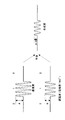
図3は、形成部400の一構成例を示すブロック図である。形成部400は、入力信号を2つの経路に分配する分配器(この図においては分岐点として示してある)と、反転器406と、切り換え器410とを備えている。切り換え器410は、出力側への接続を2つの経路の間で切り換えることによって、2つの経路を通過する信号の出力タイミングを調整する。
FIG. 3 is a block diagram illustrating a configuration example of the forming
無線受信装置30は、上述した無線送信装置20からの、OOK変調によって変調されているサブ信号列を受信し、チャネル推定を実行する。BPSK受信器による信号列a(n)と同じチャネル推定パフォーマンスを達成するため、無線受信装置30は、2つのサブ信号列a1(n)およびa2(n)の検出結果を結合する。
The
図4は、無線受信装置30のチャネル推定部212の一構成例を示すブロック図である。チャネル推定部212は、相関演算部602と、相関演算部602の出力を2つのブランチに分配する分配器(この図においては分岐点として示してある)と、遅延部604と、加算器606とを備えている。チャネル推定部212は、サブ信号列a1(n)およびa2(n)のそれぞれに係る相関を計算し、計算した相関結果を加算する。
FIG. 4 is a block diagram illustrating a configuration example of the
以上の構成を有するワイヤレス通信システム10の無線送信装置20及び無線受信装置30の動作について説明する。図5は、この動作の説明に供するフローチャートである。図6は、BPSK変調の場合にチャネル推定信号列a(n)を送信するためのパケットフォーマット(図6(a))、及び、OOK変調の場合に2つのチャネル推定サブ信号列a1(n)およびa2(n)を送信するためのパケットフォーマット(図6(b))が示されている。
Operations of the
ステップS302では、無線送信装置20が、信号列a(n)から2つのサブ信号列a1(n)およびa2(n)を生成する。具体的には、「1」および「0」のN個のバイナリビットで表された信号列a(n)が2つのブランチに分けられる。第1のブランチ402では、信号列a(n)に対して何の処理も行われず、信号列a(n)は切り換え器410にそのまま渡される。
In step S302, the
第2のブランチ404では、信号列a(n)は、反転器406に渡され、反転器406でビットが反転される。すなわち、反転器406においては、ビット「1」はビット「0」に反転され、ビット「0」はビット「1」に反転される。ビット反転処理により得られたサブ信号列a1(n)である反転器406の出力408は、切り換え器410に送られる。
In the
切り換え器410は、出力402および408を、時間をずらして変調部202に出力する。結果として、出力402および408は、連続的に連結された状態で入力信号列201として変調部202へ入力される。
The
図3において出力402および出力408は、それぞれサブ信号列a1(n)およびa2(n)として示されている。
In FIG. 3, the output 402 and the
また、図3の形成部400における処理は、以下の式(4)及び(5)のように表すことができる。なお、式(4)は第1のブランチにおける処理を表し、式(5)は第2のブランチにおける処理を表す。
![]()
![]()
![]()
![]()
この式において、Inv[ ]は、反転関数を表している。例えば、信号列a(n)が[0111]であるならば、2つのサブ信号列a1(n)およびa2(n)は、それぞれ[0111]および[1000]として計算することができる。 In this equation, Inv [] represents an inversion function. For example, if the signal sequence a (n) is [0111], the two sub-signal sequences a 1 (n) and a 2 (n) can be calculated as [0111] and [1000], respectively.
ステップS304では、無線送信装置20が、OOK変調器(変調部202)によって2つのサブ信号列a1(n)およびa2(n)を送信する。図6(b)に示したように、サブ信号列a1(n)506は、サブ信号列a2(n)508の前に送信される。OOK変調器(変調部202)は、ビット「1」に対して正の振幅+A、ビット「0」に対してゼロを設定する。
In step S304, the
ここで比較のために、従来のチャネル推定信号列の変調を図6(a)に示す。図6(a)において、信号列a(n)502がBPSK変調器504に送られ、BPSK変調器504は、ビット「1」に対して正の振幅+A、ビット「0」に対して負の振幅−Aを設定する。
Here, for comparison, FIG. 6A shows modulation of a conventional channel estimation signal sequence. In FIG. 6A, a signal sequence a (n) 502 is sent to the
なお、以上のことから、本実施の形態におけるOOK変調のためのチャネル推定信号列の長さは、BPSK変調の場合の長さの2倍である。 From the above, the length of the channel estimation signal sequence for OOK modulation in the present embodiment is twice the length in the case of BPSK modulation.
ステップS306では、OOK受信器(無線受信装置30)が2つのサブ信号列a1(n)およびa2(n)を受信する。基本的には、OOK受信器が検出できるのは、受信した信号の振幅のみである。一方でBPSK受信器は、受信信号の振幅のみならず、受信信号の極性(「+」または「−」)も検出することができる。 In step S306, the OOK receiver (wireless receiver 30) receives two sub-signal sequences a 1 (n) and a 2 (n). Basically, the OOK receiver can only detect the amplitude of the received signal. On the other hand, the BPSK receiver can detect not only the amplitude of the received signal but also the polarity (“+” or “−”) of the received signal.
ステップS308では、チャネル推定部212が、2つのサブ信号列a1(n)およびa2(n)に係る相関を計算し、計算した相関結果を加算する。
In step S308, the
具体的には、受信フィルタ208でフィルタリング処理を受けた受信信号r(n)が相関演算部602に入力され、相関演算部602は、受信信号r(n)とローカル信号列q(n)との相関をとる。
Specifically, the received signal r (n) subjected to the filtering process by the
ここでBPSK相関器では、通常、a(n)がOOK変調のため、ビット0の振幅値を「−1」にするため、「q(n)=2*a(n)−1」がローカル信号列として採用される。なぜなら、BPSK受信器は受信信号の振幅および極性を検出できるためである。ローカル信号列は、受信信号中に含まれるサブ信号列を検出するために用いられるので、信号列検出基準信号である。また、ローカル信号列は、サブ信号列の元となる信号列を基本単位とするので、その信号列のレプリカ信号でもある。
Here, in the BPSK correlator, since a (n) is usually OOK modulation, the amplitude value of
本実施の形態のOOK相関器(相関演算部602)でも、BPSK相関器と同じチャネル推定パフォーマンスを達成する目的で、同じ信号列「q(n)=2*a(n)−1」が採用される。 The same signal sequence “q (n) = 2 * a (n) −1” is also adopted in the OOK correlator (correlation calculation unit 602) of the present embodiment in order to achieve the same channel estimation performance as the BPSK correlator. Is done.
相関演算部602の出力段には、次の2つのブランチがある。
The output stage of the
まず、第1のブランチでは、出力603を加算器606に直接送る。そして、第2のブランチでは、出力603を遅延部604によって時間長Nビットだけ遅延させた後、加算器606に送る。
First, in the first branch, the
加算器606は、遅延した相関出力605と、遅延していない相関出力603との間の差分D(n)607を計算し、チャネル推定のためにその差分を後段に送出する。
The
理論的には、雑音のないチャネルにおけるD(n)は、次の式(6)のように表すことができる。
この式において、Φ[x(n),y(n)]は、2つの信号列x(n)およびy(n)の相関を表している。BPSK送信器が信号列a(n)を送るとき、BPSK受信器では信号列「q(n)=2*a(n)−1」が受信されることを理解されたい。従って、BPSK相関器の相関出力は、Φ[q(n),q(n)]に等しくもある。 In this equation, Φ [x (n), y (n)] represents the correlation between two signal sequences x (n) and y (n). It should be understood that when the BPSK transmitter sends the signal sequence a (n), the signal sequence “q (n) = 2 * a (n) −1” is received at the BPSK receiver. Therefore, the correlation output of the BPSK correlator is also equal to Φ [q (n), q (n)].
次に、インパルス応答関数がh(n)であるマルチパスチャネルを考えると、D(n)は、次の式(7)のように表すことができる。
ここで信号r1(n)およびr2(n)は、サブ信号列a1(n)およびa2(n)がマルチパスチャネルを通過した後に無線受信装置30で受信される受信信号である。またここでは、r1(n)およびr2(n)の受信中において、インパルス応答関数h(n)は変化しないものと想定する。
Here, the signals r 1 (n) and r 2 (n) are received signals that are received by the
BPSK相関器においては、ランダムな雑音の項を除いて、式(8)で表される、同じ相関出力を得ることができる。
![]()
![]()
上述したようにチャネル推定部212は、ランダムな雑音の項ではなく、チャネルインパルス応答関数h(n)の係数ak、rk、およびφkを求めるか、または推定する。従って、結論として、本実施の形態のOOK変調によるチャネル推定パフォーマンスは、BPSK変調によるチャネル推定パフォーマンスと同じである。
As described above, the
なお以上の説明では、BPSKチャネル推定信号列a(n)が1つだけ用いられる場合について説明した。しかしながら、本発明はこれに限定されるものではなく、当業者には、本発明においてBPSKチャネル推定信号列の数を2つ以上とすることができることが理解されるであろう。 In the above description, the case where only one BPSK channel estimation signal sequence a (n) is used has been described. However, the present invention is not limited to this, and those skilled in the art will understand that the number of BPSK channel estimation signal sequences can be two or more in the present invention.
すなわち、別の実施形態においては、BPSK変調によるGolay相補信号列a(n)およびb(n)をチャネル推定用に採用することができる。この場合、BPSK信号列a(n)から2つのOOKサブ信号列a1(n)およびa2(n)を導くことができ、さらにBPSK信号列b(n)から別の2つのOOKサブ信号列b1(n)およびb2(n)を導くことができる。4つのサブ信号列a1(n)、a2(n)、b1(n)、b2(n)をOOK変調器によって送信することによって、OOK受信器において、BPSK受信器と同じチャネル推定パフォーマンスを得ることができる。 That is, in another embodiment, Golay complementary signal sequences a (n) and b (n) based on BPSK modulation can be employed for channel estimation. In this case, two OOK sub-signal sequences a 1 (n) and a 2 (n) can be derived from the BPSK signal sequence a (n), and two other OOK sub-signals can be derived from the BPSK signal sequence b (n). Columns b 1 (n) and b 2 (n) can be derived. By transmitting the four sub-signal sequences a 1 (n), a 2 (n), b 1 (n), b 2 (n) by the OOK modulator, the same channel estimation in the OOK receiver as the BPSK receiver. You can get performance.
具体的には、図3において、信号列a(n)に続いて、信号列b(n)(例えば、背景技術で説明したGolay相補信号列g(n)に対応する信号列)形成部400に入力され、信号列a(n)と同様に2つのブランチに分配される。
Specifically, in FIG. 3, following the signal sequence a (n), a signal sequence b (n) (for example, a signal sequence corresponding to the Golay complementary signal sequence g (n) described in the background art) forming
次いで、第2のブランチに分配された信号列b(n)をビット反転させることによって、サブ信号列b2(n)が得られる。また、第1のブランチに分配された他方の信号列b(n)は、何らの処理を施されることなく、サブ信号列b1(n)として出力される。 Next, the signal sequence b (n) distributed to the second branch is bit-inverted to obtain the sub signal sequence b 2 (n). The other signal sequence b (n) distributed to the first branch is output as a sub signal sequence b 1 (n) without any processing.
すなわち、図6(b)において、サブ信号列a2(n)の後ろに、サブ信号列b1(n)とサブ信号列b2(n)とが連続的に形成部400から出力され、その順序でOOK変調器(変調部202)に入力される。サブ信号列a1(n)、a2(n)、b1(n)、およびb2(n)は、OOK変調器(変調部202)によってOOK変調されて、得られた変調信号が送信無線部204によって無線送信される。
That is, in FIG. 6B, after the sub signal sequence a 2 (n), the sub signal sequence b 1 (n) and the sub signal sequence b 2 (n) are continuously output from the forming
次いで、受信器において、相関演算部602が、受信したOOKサブ信号列a1(n)、a2(n)、b1(n)、およびb2(n)と、q(n)(a1(n)およびa2(n)に対しては信号列2*a(n)−1、b1(n)およびb2(n)に対しては信号列2*b(n)−1)との間の相関を計算する。さらに、加算器606が、サブ信号列a1(n)の相関結果から、サブ信号列a2(n)の相関結果を減じ、サブ信号列b1(n)の相関結果から、サブ信号列b2(n)の相関結果を減じる。この場合、上述したように、サブ信号列a1(n)の相関結果からサブ信号列a2(n)の相関結果を減じた結果は、従来のBPSKチャネル推定によって得られる相関結果、すなわち、送信器からそのまま送信されて受信器において受信されるBPSKチャネル推定信号列a(n)と、q(n)(BPSKチャネル推定信号列a(n)に対応する信号列)との間の相関結果に、理論的には一致する。
Next, in the receiver, the
同様に、サブ信号列b1(n)の相関結果からサブ信号列b2(n)の相関結果を減じた結果は、従来のBPSKチャネル推定によって得られる相関結果、すなわち、送信器からそのまま送信されて受信器において受信されるBPSKチャネル推定信号列b(n)と、q(n)(BPSKチャネル推定信号列a(n)に対応する信号列)との間の相関結果に、理論的には一致する。 Similarly, the result obtained by subtracting the correlation result of the sub signal sequence b 2 (n) from the correlation result of the sub signal sequence b 1 (n) is the correlation result obtained by the conventional BPSK channel estimation, that is, transmitted from the transmitter as it is. The correlation result between the BPSK channel estimation signal sequence b (n) received at the receiver and q (n) (the signal sequence corresponding to the BPSK channel estimation signal sequence a (n)) is theoretically Match.
さらに、サブ信号列a1(n)およびサブ信号列a2(n)に関する減算結果と、サブ信号列b1(n)およびサブ信号列b2(n)に関する減算結果とを加算する。ここで、サブ信号列a1(n)およびサブ信号列a2(n)に関する減算結果が得られるタイミングと、サブ信号列b1(n)およびサブ信号列b2(n)に関する減算結果が得られるタイミングとの間には、2Nの差がある。従って、加算処理の前に、タイミングを同期させる必要がある。 Further, the subtraction result regarding the sub signal sequence a 1 (n) and the sub signal sequence a 2 (n) and the subtraction result regarding the sub signal sequence b 1 (n) and the sub signal sequence b 2 (n) are added. Here, the timing at which the subtraction result regarding the sub signal sequence a 1 (n) and the sub signal sequence a 2 (n) is obtained, and the subtraction result regarding the sub signal sequence b 1 (n) and the sub signal sequence b 2 (n) are obtained. There is a 2N difference from the timing obtained. Therefore, it is necessary to synchronize the timing before the addition process.
従って、入力信号を2つのブランチに分配する分配器と、一方のブランチに設けられる遅延器(遅延量2N)と、2つのブランチを通過した信号を加算する加算器とを、例えば、図4の構成の後ろに(図4の構成の出力段に)設ける必要がある。 Therefore, a distributor that distributes an input signal to two branches, a delay unit (delay amount 2N) provided in one branch, and an adder that adds signals that have passed through the two branches are, for example, shown in FIG. It must be provided behind the configuration (in the output stage of the configuration of FIG. 4).
あるいは、入力信号を2つのブランチに分配する分配器を図4の構成の前に(図4の構成の入力段に)設け、2つのブランチのそれぞれに図4の構成を設けてもよい。この場合、ブランチの一方において、相関演算部602は、a1(n)およびa2(n)とq(n)(信号列2*a(n)−1)との間の相関を計算し、他方のブランチにおいて、相関演算部602は、b1(n)およびb2(n)とq(n)(信号列2*b(n)−1)との間の相関を計算する。遅延器(遅延量2N)は一方のブランチに設ければよい。そして、それぞれのブランチを通過した信号を加算する加算器が設けられる。
Alternatively, a distributor for distributing the input signal to the two branches may be provided before the configuration of FIG. 4 (in the input stage of the configuration of FIG. 4), and the configuration of FIG. 4 may be provided in each of the two branches. In this case, in one of the branches, the
またなお、以上の説明においては、BPSKチャネル推定信号列からOOKサブ信号列の導出する方法を示した。しかしながら、本発明はこれに限定されるものではなく、当業者には、BPSKチャネル推定信号列に限定されないことが理解されるであろう。別の実施形態においては、本発明の方法を採用することにより、BPSK同期信号列e(n)から2つのOOKサブ信号列e1(n)およびe2(n)を導くことができる。 In the above description, the method for deriving the OOK sub-signal sequence from the BPSK channel estimation signal sequence is shown. However, the present invention is not limited to this, and those skilled in the art will understand that the present invention is not limited to the BPSK channel estimation signal sequence. In another embodiment, by adopting the method of the present invention, two OOK sub-signal sequences e 1 (n) and e 2 (n) can be derived from the BPSK synchronization signal sequence e (n).
またなお、以上の説明においては、BPSKチャネル推定信号列からOOKチャネル推定信号列を導出し、BPSK同期信号列からOOK同期信号列を導出する方法を示している。しかしながら、本発明はこれに限定されるものではなく、OOK変調およびBPSK変調に限定されない。本発明によれば、ASK変調のためのチャネル推定信号列および同期信号列を導出できることが、当業者には理解されるであろう。BPSK変調のための信号列は、差動BPSK変調(Differential-BPSK modulation)のための信号列に置き換えることができる。 In the above description, a method of deriving an OOK channel estimation signal sequence from a BPSK channel estimation signal sequence and deriving an OOK synchronization signal sequence from a BPSK synchronization signal sequence is shown. However, the present invention is not limited to this, and is not limited to OOK modulation and BPSK modulation. Those skilled in the art will understand that according to the present invention, a channel estimation signal sequence and a synchronization signal sequence for ASK modulation can be derived. The signal sequence for BPSK modulation can be replaced with a signal sequence for differential BPSK modulation.
また、本実施の形態において使用する、BPSK変調のための推定信号列および同期信号列は、別の変調方式のための推定信号列および同期信号列を修正して得ることができる。1つの実施形態においては、16−PSK変調のためのFranck−Zadoffチャネル推定信号列a16−PSK(n)(複素数による信号列)から、BPSK変調方式のためのFranck−Zadoffチャネル推定信号列aBPSK(n)が得られる。この導出は、次の式(9)で表すことができる。
![]()
![]()
この式において、Re[x(n)]およびIm[x(n)]は、それぞれ、複素数x(n)の実部および虚部を表している。 In this equation, Re [x (n)] and Im [x (n)] represent the real part and the imaginary part of the complex number x (n), respectively.
すなわち、信号列c(n)の実部が信号列c(n)の虚部よりも大きい場合、または、信号列c(n)の実部と虚部の両方が0に等しいか若しくは0よりも大きい場合に、信号列a(n)に第1のビット値を設定し、且つ、信号列c(n)の実部が信号列c(n)の虚部よりも小さい場合、または、信号列c(n)の実部と虚部の両方が0に等しいか若しくは0よりも小さい場合に、信号列a(n)に第2のビット値を設定する。ここでは、第1のビット値が正のビット値「+1」であり、第2のビット値が負のビット値「−1」である。 That is, when the real part of the signal sequence c (n) is larger than the imaginary part of the signal sequence c (n), or both the real part and the imaginary part of the signal sequence c (n) are equal to 0 or more than 0 Is set to the first bit value in the signal sequence a (n) and the real part of the signal sequence c (n) is smaller than the imaginary part of the signal sequence c (n), or the signal When both the real part and the imaginary part of the column c (n) are equal to or smaller than 0, the second bit value is set in the signal sequence a (n). Here, the first bit value is a positive bit value “+1”, and the second bit value is a negative bit value “−1”.
(実施の形態2)
実施の形態1では、OOK変調信号に最適なチャネル推定信号列を送受信する無線送信装置及び無線受信装置について説明している。これに対して、実施の形態2では、チャネル推定の結果に基づいて、受信信号の振幅を補正する無線受信装置及びその補正方法について説明する。なお、本実施の形態では送信信号は、OOKで変調される。また、図7に示すように、無線送信装置20と無線受信装置800との間の伝送路は、直接波701と地面、机、壁などの反射体702からの反射波703との2波で構成される2波モデルでモデル化する。
(Embodiment 2)
In the first embodiment, a wireless transmission device and a wireless reception device that transmit and receive a channel estimation signal sequence optimal for an OOK modulation signal are described. On the other hand, in the second embodiment, a radio reception apparatus that corrects the amplitude of a received signal based on the result of channel estimation and a correction method thereof will be described. In this embodiment, the transmission signal is modulated by OOK. As shown in FIG. 7, the transmission path between the
図8は、本発明の実施の形態2に係る無線受信装置800の構成を示すブロック図である。図2に示す無線受信装置30と同じ構成要素には同じ符号を付し、その説明を省略する。
FIG. 8 is a block diagram showing a configuration of
図8において無線受信装置800は、アンテナと、受信フィルタ208、検波部804、及びサンプル部806を有する受信無線部206と、チャネル推定部212と、等化器(イコライザ)210と、二値化部808とを備えている。
In FIG. 8, a
アンテナは、無線送信装置20から送信された信号を受信し、受信信号207を受信フィルタ208へ出力する。
The antenna receives the signal transmitted from the
受信フィルタ208は、受信信号の帯域を制限することで、受信信号から所望帯域外の雑音を除去する。そして受信フィルタ208は、雑音を除去した受信信号209を検波部804へ出力する。
The
検波部804は、雑音が除去された受信信号209に対して所定の検波処理を行う。所定の検波処理とは、例えば、同期検波、遅延検波、包絡線検波等である。そして検波部804は、雑音が除去された受信信号209を検波することで得られる検波信号801をサンプル部806へ出力する。なお、本実施の形態において検波部804は、同期検波を行う。
The
サンプル部806は、検波信号801を所定のサンプルタイミングでサンプルし、サンプル値803をチャネル推定部212、およびイコライザ210へ出力する。
The
サンプル部806は、例えば、ADC(Analog to Digital Converter)を備えており、シンボルレートのM倍(Mは、正の数)のサンプルレートで検波信号801をサンプルする。本実施の形態では、一例としてM=1として説明する。従って、検波信号1シンボルに対して1つのサンプル値が得られる。
The
チャネル推定部212は、図9に示すように、相関演算部602、遅延部604、加算器606、係数算出部900を備える。ここで相関演算部602、遅延部604、加算器606は、実施の形態1に記述した処理と同様の処理を行う。
The
係数算出部900は、加算器606から出力される加算値607を用いて実施の形態1において記述した係数ak、rk、φkを算出する。ただし、k=1、・・・、Lであり、Lは、検出可能な遅延波の数である。
The
そして係数算出部900は、算出した係数ak、rk、φkをチャネル推定結果901としてイコライザ210へ出力する。本実施の形態では、伝送路を2波モデルでモデル化しているため、L=2で、k=1,2である。
Then, the
ここで係数ak、rk、φkの具体的な算出方法について説明する。 Here, a specific calculation method of the coefficients a k , r k , and φ k will be described.
係数算出部900は、N(Nは、チャネル推定信号列の長さ)個の加算値607の中から、絶対値が大きい順にL個の加算値を検出する。ここではk=1、2なので、a1とa2が検出される。
次に、係数算出部900は、akが検出された時刻rkを検出する。例えば、a1がN個の加算値607のi番目、a2がj(j>i)番目に検出された場合、r1=i、r2=jとなる。一般的に直接波は遅延波よりも前に受信されるので、j>iならば、a1の絶対値|a1|が直接波の振幅、a2の絶対値|a2|が遅延波の振幅を表す。またここでは検波信号1シンボル(OOK変調であるので、1ビットに対応する)に対して1つのサンプル値を取得するサンプル周波数が適用されているので、遅延波は直接波よりもr2−r1=j−iビット遅れて受信されることが分かる。
Next,
次に、係数算出部900は、akに対応する波の位相φkを検出する。実際の無線通信においてφkは、−180°〜+180°の任意の値をとり得る。しかし、本実施の形態では、簡易に位相を推定するために、φkは0°または180°の2つ位相状態をとるものとして検出される。具体的には、φkは、ak≧0であるとき、φk=0°として検出される一方、|ak<0であるときφk=180°として検出される。本実施の形態では、φ1とφ2の差が、直接波と遅延波との位相差を表す。
Next, the
以上のようにして、係数算出部900は、チャネル推定結果901として係数ak、rk、φkを算出する。
As described above, the
図8に戻ってイコライザ210は、チャネル推定部212から出力されるチャネル推定結果901と、二値化部808から出力される復調結果805とを用いて、サンプル部806から出力されるサンプル値803の振幅を補正する。
Returning to FIG. 8, the
二値化部808は、イコライザ210によって振幅を補正されたサンプル値214を所定の閾値thと比較することで二値化し、二値化した結果を復調結果805として出力する。復調結果805は、イコライザ210へも出力される。
The
ここで二値化部808における二値化方法と、イコライザ210における振幅補正方法について説明する。なお、検波信号801は、サンプル部806、チャネル推定部212、イコライザ210によって所定の処理が施されるが、ここでは簡単化のため、これらの処理の説明を省く。すなわち、検波信号801は、直接二値化部808へ入力されるものとする。
Here, the binarization method in the
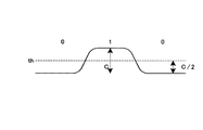
まず、二値化部808におけるOOK変調信号の二値化方法を図10と図11を用いて説明する。図11は、反射波が存在しない環境においてOOK変調信号“010”を受信したときの受信信号209を示す図である。OOKでは、ビット“1”に対して振幅A、ビット“0”に対して振幅0を割当てられる。従って、雑音が除去された受信信号209は、図10のようになる。
First, the binarization method of the OOK modulation signal in the
雑音が除去された受信信号209は、検波部804で検波処理が施される。その結果、検波信号801は、図11のようになる。検波処理の結果、ビット“1”に対応する振幅は、Cになる。ここで、Cは、装置設計で決まる値であり、ビット“1”を受信したときに想定される検波信号の振幅である。
The received
二値化部808は、検波信号801の振幅を所定の閾値thと比較することによって、検波信号801を二値化し、二値化した結果を復調結果805として出力する。図11に示すように、ビット“1”に対応する検波信号801の振幅がCのとき、閾値thの値は、通常、C/2に設定される。
The
そして二値化部808は、例えば検波信号801の振幅がC/2以上のときに“1”に二値化し、検波信号801の振幅がC/2未満のときに“0”に二値化する。こうして二値化部808は、検波信号801を二値化する。
For example, the
次に、イコライザ210におけるサンプル値803の振幅補正方法について図12〜図19を用いて説明する。本実施の形態では、伝送路を2波モデルと仮定している。またここでは、直接波と遅延波の位相差が、0°と180°の場合を例にとり説明する。なお、具体的な、入力波形の干渉状態の判断については、後述する。
Next, a method for correcting the amplitude of the
図12は、直接波のビット“1”に遅延波のビット“1”が、直接波と遅延波との位相差が0°の状態で干渉した場合の合成波(受信した信号)を示す。図12に示すように、直接波の振幅をA、遅延波の振幅をBとすると、合成波の振幅はA+Bとなる。無線受信装置800が図12の合成波を受信した場合、検波信号801の振幅は、図13に示すようにD(D>C)となる。従って、直接波のビット“1”に遅延波のビット“1”が位相差0°で干渉した場合、二値化部808の処理結果において、遅延波に起因するビット誤りは発生しない。
FIG. 12 shows a composite wave (received signal) in the case where the bit “1” of the direct wave interferes with the bit “1” of the direct wave in a state where the phase difference between the direct wave and the delay wave is 0 °. As shown in FIG. 12, when the amplitude of the direct wave is A and the amplitude of the delayed wave is B, the amplitude of the combined wave is A + B. When the
図14は、直接波のビット“1”に遅延波のビット“1”が位相差180°で干渉した場合の合成波を示す。図14に示すように、直接波の振幅をA、遅延波の振幅をBとすると、合成波の振幅はA−Bとなる。無線受信装置800が図14の合成波を受信した場合、検波信号801の振幅は、図15に示すようにE(E<C)となる。特に、B>A/2の場合、E<C/2となる。すなわち、直接波のビット“1”と一致した二値化結果が得られるべきところ、二値化部808では、ビット“0”と判定される。従って、直接波のビット“1”に遅延波のビット“1”が位相差180°で干渉した場合、二値化部808の処理結果において、遅延波に起因するビット誤りが発生する。
FIG. 14 shows a composite wave when the bit “1” of the delay wave interferes with the bit “1” of the direct wave with a phase difference of 180 °. As shown in FIG. 14, when the amplitude of the direct wave is A and the amplitude of the delayed wave is B, the amplitude of the synthesized wave is AB. When the
図16は、直接波のビット“0”に遅延波のビット“1”が位相差0°で干渉した場合の合成波を示す。図16に示すように、直接波の振幅を0、遅延波の振幅をBとすると、合成波の振幅はBとなる。無線受信装置800が図16の合成波を受信した場合、検波信号801の振幅は、図17に示すようにF(F>0)となる。特に、B>A/2の場合、F>C/2となる。すなわち、直接波のビット“0”と一致した二値化結果が得られるべきところ、二値化部808では、ビット“1”と判定される。従って、直接波のビット“0”に遅延波のビット“1”が位相差0°で干渉した場合、二値化部808の処理結果において、遅延波に起因するビット誤りが発生する。
FIG. 16 shows a composite wave when the bit “0” of the delayed wave interferes with the bit “0” of the direct wave with a phase difference of 0 °. As shown in FIG. 16, if the amplitude of the direct wave is 0 and the amplitude of the delayed wave is B, the amplitude of the synthesized wave is B. When the
図18は、直接波のビット“0”に遅延波のビット“1”が位相差180°で干渉した場合の合成波を示す。図18に示すように、直接波の振幅を0、遅延波の振幅をBとすると、合成波の振幅はBとなる。無線受信装置800が図18の合成波を受信した場合、検波信号801の振幅は、図19に示すようにG(G=F>0)となる。特に、B>A/2の場合、G>C/2となる。すなわち、直接波のビット“0”と一致した二値化結果が得られるべきところ、二値化部808では、ビット“1”と判定される。従って、直接波のビット“0”に遅延波のビット“1”が位相差180°で干渉した場合、二値化部808の処理結果において、遅延波に起因するビット誤りが発生する。
FIG. 18 shows a combined wave when the delayed wave bit “1” interferes with the direct wave bit “0” with a phase difference of 180 °. As shown in FIG. 18, if the amplitude of the direct wave is 0 and the amplitude of the delayed wave is B, the amplitude of the synthesized wave is B. When the
なお、遅延波がビット“0”の場合、遅延波の振幅は0なので、直接波に遅延波が干渉してもビット誤りは発生しない。 When the delay wave is bit “0”, since the amplitude of the delay wave is 0, no bit error occurs even if the delay wave interferes with the direct wave.
以上を考慮すると、検波信号801の振幅補正は、直接波のビット、遅延波のビット、直接波と遅延波の位相差に応じて、以下のように行われる必要がある。ここで、図10、図11から、振幅Aの直接波を検波した結果、振幅Cの検波信号が得られるので、検波部804の検波処理によって受信信号209の振幅が線形変換されるとすれば、検波部804は、受信信号209の振幅をC/A倍にして出力する。なお、イコライザ210の出力をHとおく。
Considering the above, the amplitude correction of the
(1)直接波がビット“1”、遅延波がビット“1”、直接波と遅延波の位相差が0°の場合
この場合には受信信号209の振幅はA+Bなので、検波信号801の振幅Dは、D=(A+B)×C/Aとなる。チャネル推定結果からA:B=|a1|:|a2|が成り立つので、D=(A+A×|a2|/|a1|)×C/A=C×(1+|a2|/|a1|)となる。従ってイコライザ210は、式(10)で示されるように、検波信号801の振幅をDからCに補正する。すなわち、イコライザ210は、検波信号801の振幅を、遅延波の干渉がない理想状態における振幅に換算している。
(2)直接波がビット“1”、遅延波がビット“1”、直接波と遅延波の位相差が180°の場合
この場合には受信信号の振幅はA−Bなので、検波信号801の振幅Eは、E=(A−A×|a2|/|a1|)×C/A=C×(1−|a2|/|a1|))となる。従ってイコライザ210は、式(11)で示されるように、検波信号801の振幅をEからCに補正する。
(3)直接波がビット“1”、遅延波がビット“0”、直接波と遅延波の位相差が0°の場合
この場合には遅延波の振幅は0なので、検波信号801の振幅はCである。従って、イコライザ210は、検波信号801の振幅を補正することなく、そのまま出力する。
(3) When the direct wave is bit “1”, the delayed wave is bit “0”, and the phase difference between the direct wave and the delayed wave is 0 ° In this case, since the amplitude of the delayed wave is 0, the amplitude of the
(4)直接波がビット“1”、遅延波がビット“0”、直接波と遅延波の位相差が180°の場合
この場合には遅延波の振幅は0なので、検波信号801の振幅はCである。従って、イコライザ210は、検波信号801の振幅を補正することなく、そのまま出力する。
(4) When the direct wave is bit “1”, the delayed wave is bit “0”, and the phase difference between the direct wave and the delayed wave is 180 ° In this case, the amplitude of the delayed wave is 0, so the amplitude of the
(5)直接波がビット“0”、遅延波がビット“1”、直接波と遅延波の位相差が0°の場合
この場合にはイコライザ210は、検波信号801の振幅をFから0に補正する。すなわち、式(12)で表される補正処理が行われる。
![]()
![]()
(6)直接波がビット“0”、遅延波がビット“1”、直接波と遅延波の位相差が180°の場合
この場合にはイコライザ210は、検波信号801の振幅をGから0に補正する。すなわち、式(13)で表される補正処理が行われる。
![]()
![]()
(7)直接波がビット“0”、遅延波がビット“0”、直接波と遅延波の位相差が0°の場合
この場合には遅延波の振幅は0なので、検波信号801の振幅は0である。従って、イコライザ210は、検波信号801の振幅を補正することなくそのまま出力する。
(7) When the direct wave is bit “0”, the delayed wave is bit “0”, and the phase difference between the direct wave and the delayed wave is 0 ° In this case, since the amplitude of the delayed wave is 0, the amplitude of the
(8)直接波がビット“0”、遅延波がビット“0”、直接波と遅延波の位相差が180°の場合
この場合には遅延波の振幅は0なので、検波信号801の振幅は0である。従って、イコライザ210は、検波信号801の振幅を補正することなくそのまま出力する。
(8) When the direct wave is bit “0”, the delayed wave is bit “0”, and the phase difference between the direct wave and the delayed wave is 180 ° In this case, since the amplitude of the delayed wave is 0, the amplitude of the
以上のように直接波と遅延波との干渉状態は、直接波のビット、遅延波のビット、および、直接波と遅延波の位相差に応じて8通りある。しかし、遅延波のビットが“0”の場合(上記したケース(3)、(4)、(7)、(8))では、イコライザ210は、補正処理を行わない。すなわち、ケース(3)、(4)、(7)、(8)を区別する必要はない。
As described above, there are eight interference states between the direct wave and the delayed wave according to the direct wave bit, the delayed wave bit, and the phase difference between the direct wave and the delayed wave. However, in the case where the bit of the delayed wave is “0” (the above cases (3), (4), (7), (8)), the
従って、実際には、イコライザ210は、(1)、(2)、(5)、(6)、(9)(=(3)、(4)、(7)、または(8))の5つの状態を検出し、それぞれの状態に適した補正処理を行う。
Therefore, in practice, the
次に、イコライザ210における上記5つの状態の判別方法について説明する。
Next, a method for determining the five states in the
イコライザ210は、チャネル推定結果901と復調結果805とを用いて上記5つの状態を判別する。ここで、チャネル推定の結果、直接波を表す係数はそれぞれa1=Ai、r1=i、φ1=φiであり、遅延波を表す係数はa2=Aj、r2=j、φ2=φjである。また、時刻mにおけるサンプル値803をUm、サンプル値803の復調結果805をVmとおく。
The
そうすると、下記のようにして(1)、(2)、(5)、(6)、(9)の状態を判別できる。 Then, the states of (1), (2), (5), (6), and (9) can be determined as follows.
I)Vm−(j−i)、すなわち、時刻mよりもj−iだけ前のタイミングにおける復調結果が0ならば、遅延波のビットが“0”ということなので、イコライザ210は、時刻mにおける状態を(9)と判断する。
I) V m− (j−i) , that is, if the demodulation result at timing j−i prior to time m is 0, the bit of the delayed wave is “0”, so the
II)Vm−(j−i)=1、|φ1−φ2|=0°、且つ、Um≧Cならば、イコライザ210は、時刻mにおける状態を(1)と判断する。
II) If V m− (j−i) = 1, | φ 1 −φ 2 | = 0 ° and U m ≧ C, the
III)Vm−(j−i)=1、|φ1−φ2|=180°、C>Um≧C/2、且つ、|a2|/|a1|≦0.5ならば、イコライザ210は、時刻mにおける状態を(2)と判断する。
III) If V m− (j−i) = 1, | φ 1 −φ 2 | = 180 °, C> U m ≧ C / 2, and | a 2 | / | a 1 | ≦ 0.5 The
IV)Vm−(j−i)=1、|φ1−φ2|=180°、Um<C/2、且つ|a2|/|a1|>0.5ならば、イコライザ210は、時刻mにおける状態を(2)と判断する。
IV) If V m− (j−i) = 1, | φ 1 −φ 2 | = 180 °, U m <C / 2, and | a 2 | / | a 1 |> 0.5, the
V)Vm−(j−i)=1、|φ1−φ2|=0°、C>Um≧C/2、且つ、|a2|/|a1|≧0.5ならば、イコライザ210は、時刻mにおける状態を(5)と判断する。
V) If V m− (j−i) = 1, | φ 1 −φ 2 | = 0 °, C> U m ≧ C / 2, and | a 2 | / | a 1 | ≧ 0.5 The
VI)Vm−(j−i)=1、|φ1−φ2|=0°、Um<C/2、且つ|a2|/|a1|<0.5ならば、イコライザ210は、時刻mにおける状態を(5)と判断する。
VI) If V m− (j−i) = 1, | φ 1 −φ 2 | = 0 °, U m <C / 2, and | a 2 | / | a 1 | <0.5, the
VII)Vm−(j−i)=1、|φ1−φ2|=180°、C>Um≧C/2、且つ、|a2|/|a1|≧0.5ならば、イコライザ210は、時刻mにおける状態を(6)と判断する。
VII) If V m− (j−i) = 1, | φ 1 −φ 2 | = 180 °, C> U m ≧ C / 2, and | a 2 | / | a 1 | ≧ 0.5 The
VIII)Vm−(j−i)=1、|φ1−φ2|=180°、Um<C/2、且つ|a2|/|a1|<0.5ならば、イコライザ210は、時刻mにおける状態を(6)と判断する。
VIII) If V m− (j−i) = 1, | φ 1 −φ 2 | = 180 °, U m <C / 2, and | a 2 | / | a 1 | <0.5, the
以上のように本実施の形態によれば、イコライザ210は、加算器606で算出されたN個の差分情報の中から抽出されたL個(L≦N)の差分情報の値d(k)(ただし、k=1、2、・・・、L)、その絶対値|d(k)|、d(k)の符号の正負、差分情報を抽出した位置r(k)、および位相情報φ(k)のうち少なくとも一つを検出し、当該検出結果と復調結果(本実施の形態では、二値化結果)とに基づいて直接波と間接波との干渉状態(つまり、直接波のビット値、間接波のビット値、および直接波と間接波との位相差で特定される干渉状態)を判断する。そして、イコライザ210は、干渉状態に応じた、検波信号801の振幅の補正を行う。
As described above, according to the present embodiment, the
すなわち、イコライザ210は、加算器606で算出されたN個の差分情報の中から抽出されたL個(L≦N)の差分情報の値d(k)、その絶対値|d(k)|、d(k)の符号の正負、差分情報を抽出した位置r(k)、および位相情報φ(k)のうち少なくとも一つを検出し、当該検出結果と復調結果とに基づいて検波信号801の振幅を補正する。
That is, the
こうして直接波と遅延波との干渉状態に即して検波信号801の振幅を補正するので、二値化結果におけるビット誤り率を改善することができる。
In this way, the amplitude of the
(実施の形態3)
実施の形態2では、イコライザ210が、直接波のビット、遅延波のビット、直接波と遅延波の位相差に応じて検波信号801の振幅を補正する。これに対して、実施の形態3では、後述する閾値制御部902が直接波のビット、遅延波のビット、直接波と遅延波の位相差に応じて、二値化部808の閾値thを制御する。
(Embodiment 3)
In the second embodiment, the
図20は、本発明の実施の形態3に係る無線受信装置1000の構成を示すブロック図である。イコライザ210の代わりに閾値制御部902を備える点が実施の形態2の無線受信装置800と異なる。
FIG. 20 is a block diagram showing a configuration of
閾値制御部902は、直接波のビット、遅延波のビット、直接波と遅延波の位相差に応じた閾値制御信号903を二値化部808へ出力する。
The
以下で閾値制御部902の動作について説明する。
The operation of the
閾値制御部902は、実施の形態2のイコライザ210と同様に、I)〜VIII)の判定条件を用いて、(1)、(2)、(5)、(6)、(9)の状態を判別する。そして閾値制御部902は(1)、(2)、(5)、(6)、(9)の状態に応じて以下のように閾値制御を行う。
Similar to the
(ケースA)
(1)、(5)、(6)の状態は、いずれも、受信信号の振幅が遅延波の干渉によって増加している状態である。従って、同じ閾値制御を適用できる。
(Case A)
The states (1), (5), and (6) are all states in which the amplitude of the received signal increases due to delay wave interference. Therefore, the same threshold control can be applied.
(1)の状態を例に説明すると、Cは次の式(14)で表される。
この式(14)をDについてまとめると、式(15)のように表される。
最適な閾値Tは、D/2なので、式(16)により求めることができる。
このようにして閾値制御部902は、閾値を制御する。すなわち、検波信号801の振幅と二値化部808に設定される設定閾値との関係が、遅延波の干渉がない理想状態における振幅Dと閾値th(つまり、D/2)との関係になるように、閾値制御部902は、設定閾値を制御する。
In this way, the
(ケースB)
(2)の状態が検出されたとき、Cは次の式(17)で表される。
When the state of (2) is detected, C is expressed by the following equation (17).
この式(17)をEについてまとめると、式(18)のように表される。
最適な閾値Tは、E/2なので、式(19)により求めることができる。
(ケースC)
(9)の状態が検出されたときは、遅延波のビットが“0”なので、直接波は干渉の影響を受けない。従って、閾値はT=thのままである。
(Case C)
When the state of (9) is detected, since the bit of the delayed wave is “0”, the direct wave is not affected by interference. Therefore, the threshold value remains T = th.
以上のように本実施の形態によれば、閾値制御部902は、加算器606で算出されたN個の差分情報の中から、L個(L≦N)の差分情報を抽出し、当該L個の差分情報の値d(k)、その絶対値|d(k)|、d(k)の符号の正負、差分情報を抽出した位置r(k)、および位相情報φ(k)のうち少なくとも一つを検出し、当該検出結果と復調結果(本実施の形態では、二値化結果)とに基づいて直接波と間接波との干渉状態(つまり、直接波のビット値、間接波のビット値、および直接波と間接波との位相差で特定される干渉状態)を判断する。そして、閾値制御部902は、干渉状態に応じた、二値化部808の閾値の補正を行う。
As described above, according to the present embodiment, the
すなわち、閾値制御部902は、加算器606で算出されたN個の差分情報の中から、L個(L≦N)の差分情報を抽出し、当該L個の差分情報の値d(k)、その絶対値|d(k)|、d(k)の符号の正負、差分情報を抽出した位置r(k)、および位相情報φ(k)のうち少なくとも一つを検出し、当該検出結果と復調結果とに基づいて二値化部808の閾値を補正する。
That is, the
こうして直接波と遅延波との干渉状態に即して二値化部808の閾値thを補正するので、二値化結果におけるビット誤り率を改善することができる。
In this way, the threshold th of the
(実施の形態4)
本発明の実施の形態4では、実施の形態1乃至3のそれぞれで説明されたチャネル推定部のチャネル推定精度を向上する方法について説明する。
(Embodiment 4)
In the fourth embodiment of the present invention, a method for improving the channel estimation accuracy of the channel estimator described in each of the first to third embodiments will be described.
図21は、本発明の実施の形態4における送信データのフレーム構成を示す図である。チャネル推定信号列108は、サブ信号列1001、サブ信号列1002、サブ信号列1003で構成されている。チャネル推定信号列108は、形成部400により形成される。
FIG. 21 is a diagram showing a frame structure of transmission data according to Embodiment 4 of the present invention. The channel
ここで、C1(n)(サブ信号列1001、サブ信号列1003)と、C2(n)(サブ信号列1002)とは、実施の形態1におけるサブ信号列a1(n)とサブ信号列a2(n)と同様の関係にある。すなわち、サブ信号列C1(n)、C2(n)は、BPSK用に作られた長さNビットのチャネル推定信号列C(n)から生成される。また、C1(n)とC2(n)は、互いにビットが反転した関係にある。
Here, C 1 (n) (
図22は、相関演算部602で得られる相関値603の一例を示す図である。
FIG. 22 is a diagram illustrating an example of the
図22において、最初のN個の相関値603_1がサブ信号列1001に対する相関値であり、次のN個の相関値603_2がサブ信号列1002に対する相関値であり、最後のN個の相関値603_3がサブ信号列1003に対する相関値である。
In FIG. 22, the first N correlation values 603_1 are correlation values for the
サブ信号列1001、1003と、サブ信号列1002とは、ビットが反転した関係にあるので、相関値603_1および603_3と、相関値603_2とは反転した関係になる。
Since the
図23は、実施の形態4におけるチャネル推定部212の構成を示す図である。実施の形態4におけるチャネル推定部212は、遅延部604の代わりにチャネル推定信号列(CES:Channel Estimation Sequence)抽出部904を備える点が、チャネル推定部212と異なる。
FIG. 23 is a diagram showing a configuration of
図21のフレーム構成によれば、チャネル推定信号列108は、同期信号列106とペイロード104に挟まれている。相関演算部602における相関演算は、長さNのサブ信号列候補に対してローカル信号列を段階的にずらし、各段階で行われる。そのため、相関値603_1の前半のN/2個の相関値には、同期信号列106とローカル信号列C(n)との相関値が含まれている。また、相関値603_3の後半のN/2個の相関値にも、ペイロード104とローカル信号列C(n)との相関値が含まれている。
According to the frame configuration of FIG. 21, the channel
従って、実施の形態1乃至3のチャネル推定部212の構成を用いてチャネル推定を行うと、本来チャネル推定には用いない信号列すなわち同期信号列106、ペイロード104との相関値が含まれてしまうのでチャネル推定精度が劣化してしまう。
Therefore, when channel estimation is performed using the configuration of
この劣化を改善するために、実施の形態4のチャネル推定部212では、CES抽出部904が以下の処理を行う。
In order to improve this deterioration, in the
まず、CES抽出部904は、図24に示すように相関値603_1から後半のN/2の相関値(これをX1とする)を抽出する。
First,
次に、CES抽出部904は、相関値603_2の値(これをX2とする)を記憶する。
Next,
次に、CES抽出部904は、図24に示すように相関値603_3から前半のN/2個の相関値(これをX3とする)を抽出する。
Next, as shown in FIG. 24, the
次に、CES抽出部904は、図24に示すようにX1をX3の後ろに結合させる。こうして結合された相関値群をX4とすると、X4は、長さNの信号列になる。
Next, the
最後に、CES抽出部904は、X4とX2の差分905を計算する。
Finally,
以上のように、CES抽出部904が、本来チャネル推定に使用されない信号列の相関値が含まれないX1とX3を用いて、サブ信号列C1(n)に対する新たな相関値X4を形成し、係数算出部900が、X4とX2の差分905を用いてチャネル推定結果901を計算することで、チャネル推定精度を向上することができる。
As described above, the
なお、図21の同期信号列106が、チャネル推定信号列を構成する信号列、例えばC1(n)やC2(n)で構成されている場合には、同期信号列106の相関演算結果603をチャネル推定に用いることができる。すなわち、同期信号列106の最後の部分と、チャネル信号列の最初の部分とを同じサブ信号列とすることにより、相関値603_1の前半のN/2個の相関値もチャネル推定に用いることができるので、チャネル推定精度を更に向上することができる。
When the
(他の実施の形態)
実施の形態2及び実施の形態3において説明した振幅補正処理、及び、閾値補正処理は、実施の形態1及び4で説明したフレーム構成に限定されるものでなく、OOK変調方式で通信が行われる場合の全般に適用することができる。
(Other embodiments)
The amplitude correction process and the threshold correction process described in the second and third embodiments are not limited to the frame configuration described in the first and fourth embodiments, and communication is performed using the OOK modulation method. Applicable to all cases.
(1)図25は、OOK受信装置1100の構成を示すブロック図である。OOK受信装置1100は、チャネル推定部1110を有する。
(1) FIG. 25 is a block diagram showing the configuration of the
OOK受信装置1100は、送信側からOOK変調方式で送信された信号を受信する。送信側から送信される信号には、チャネル推定信号列が含まれる。受信無線部206により受信処理が施された受信信号は、イコライザ210およびチャネル推定部1110に入力される。
The
チャネル推定部1110は、受信信号と、チャネル推定信号列を基本単位とするローカル信号列との相関をとる。これにより遅延プロファイルが得られる。
チャネル推定部1110は、遅延プロファイルに現れるピークに対応する係数ak、rk、φk(つまり、チャネル推定結果)を求め、イコライザ210に出力する。
イコライザ210は、直接波に対応するピークが現れるタイミングと遅延波に対応するピークが現れるタイミングとの間の時間差だけ、現時点よりも前のタイミングにおける復調結果に基づいて、その遅延波のビットを判定する。そして、イコライザ210は、「当該判定結果(遅延波のビット)」、「直接波と遅延波との位相差」、「現時点で受信信号がサンプリングされたサンプル値」、および、「直接波に対応するピークの振幅と遅延波に対応するピークの振幅との比」に基づいて、直接波と間接波との干渉状態を判断する。つまり、イコライザ210は、直接波のビット値、間接波のビット値、および直接波と間接波との位相差で特定される干渉状態を判断する。そして、イコライザ210は、干渉状態に応じた、検波信号801の振幅の補正を行う。
The
イコライザ210は、特に、遅延波のビットが1であると判定した場合、「直接波と遅延波との位相差」、「現時点で受信信号がサンプリングされたサンプル値」、および「直接波に対応するピークの振幅と遅延波に対応するピークの振幅との比」、に応じた補正を行う。なお、イコライザ210は、遅延波のビットが0であると判定した場合には、補正を行わない。
In particular, when the
こうして直接波と遅延波との干渉状態に即して検波信号801の振幅を補正するので、二値化結果におけるビット誤り率を改善することができる。
In this way, the amplitude of the
(2)図26は、OOK受信装置1200の構成を示すブロック図である。OOK受信装置1200は、チャネル推定部1110を有する。
(2) FIG. 26 is a block diagram showing a configuration of the
OOK受信装置1100は、送信側からOOK変調方式で送信された信号を受信する。送信側から送信される信号には、チャネル推定信号列が含まれる。受信無線部206により受信処理が施された受信信号は、チャネル推定部1110および二値化部808に入力される。
The
チャネル推定部1110は、受信信号と、チャネル推定信号列を基本単位とするローカル信号列との相関をとる。これにより遅延プロファイルが得られる。
チャネル推定部1110は、遅延プロファイルに現れるピークに対応する係数ak、rk、φk(つまり、チャネル推定結果)を求め、閾値制御部902に出力する。
閾値制御部902は、直接波に対応するピークが現れるタイミングと遅延波に対応するピークが現れるタイミングとの間の時間差だけ、現時点よりも前のタイミングにおける復調結果に基づいて、その遅延波のビットを判定する。
The
そして、閾値制御部902は、「当該判定結果」、「直接波と遅延波との位相差」、「現時点で受信信号がサンプリングされたサンプル値」、および「直接波に対応するピークの振幅と遅延波に対応するピークの振幅との比」に基づいて、直接波と間接波との干渉状態を判断する。つまり、閾値制御部902は、直接波のビット値、間接波のビット値、および直接波と間接波との位相差で特定される干渉状態を判断する。そして、閾値制御部902は、干渉状態に応じた、二値化部808の閾値の補正を行う。
Then, the
閾値制御部902は、特に遅延波のビットが1であると判定した場合、「直接波と遅延波との位相差」、「現時点で受信信号がサンプリングされたサンプル値」、および「直接波に対応するピークの振幅と遅延波に対応するピークの振幅との比」に応じた補正を行い、遅延波のビットが0であると判定した場合には、補正を行わない。
When the threshold
こうして直接波と遅延波との干渉状態に即して二値化部808の閾値thを補正するので、二値化結果におけるビット誤り率を改善することができる。
In this way, the threshold th of the
なお、すべてまたは一部の図面は、説明を目的とする概略的な表現であり、図中の要素の実際の相対的な大きさや位置を必ずしも描いていない。これらの図面は、本発明の1つ以上の実施形態を説明する目的で提供するものであり、請求項の範囲または概念を制限するものではないことを理解されたい。 All or some of the drawings are schematic representations for the purpose of explanation, and do not necessarily depict actual relative sizes and positions of elements in the drawings. It should be understood that these drawings are provided for purposes of illustrating one or more embodiments of the invention and are not intended to limit the scope or concept of the claims.
本発明の無線通信方法、無線送信装置、及び、無線受信装置は、受信処理のために用意されている信号列であって第2変調方式で用いられる信号列から生成可能な第1変調方式での受信処理に用いられる信号系列を採用することで、第2変調方式での受信処理パフォーマンスと同程度のパフォーマンスを実現できるものとして有用である。 The wireless communication method, the wireless transmission device, and the wireless reception device of the present invention are signal sequences prepared for reception processing, and are generated using a first modulation scheme that can be generated from a signal sequence used in the second modulation scheme. By adopting the signal sequence used for the reception processing, it is useful as a device that can realize performance comparable to the reception processing performance in the second modulation scheme.
10 ワイヤレス通信システム
20 無線送信装置
30,800,1000,1100,1200 無線受信装置
202 変調部
204 送信無線部
206 受信無線部
208 受信フィルタ
210 イコライザ
212,1110 チャネル推定部
400 形成部
406 反転器
410 切り換え器
602 相関演算部
604 遅延部
606 加算器
804 検波部
806 サンプル部
808 二値化部
900 係数算出部
902 閾値制御部
904 CES抽出部
DESCRIPTION OF
Claims (15)
前記無線送信装置において、位相変調方式用に設計されている第2のシーケンスa(n)と実質的に同一のシーケンスであるサブシーケンスa1(n)と、前記第2のシーケンスa(n)とビットが反転しているサブシーケンスa2(n)とを時間的に連結することにより前記第1のシーケンスを生成し、前記生成した第1のシーケンスを位相変調を含まない変調方式により変調するステップと、
前記変調後の第1のシーケンスを送信するステップと、
を含む無線送信方法。 A wireless transmission method for transmitting a first sequence for channel estimation from a wireless transmission device by a modulation scheme not including phase modulation ,
In the wireless transmission device, a subsequence a 1 (n) is substantially the same sequence and the second sequence a (n) that is designed for phase modulation system, the second sequence a (n) And the subsequence a 2 (n) whose bits are inverted are temporally connected to generate the first sequence, and the generated first sequence is modulated by a modulation scheme not including phase modulation. Steps,
Transmitting the modulated first sequence;
A wireless transmission method including :
位相変調方式用に設計されている第2のシーケンスa(n)と実質的に同一のシーケンスであるサブシーケンスa1(n)と、前記第2のシーケンスa(n)とビットが反転しているサブシーケンスa2(n)とを時間的に連結することにより前記第1のシーケンスを生成し、前記生成した第1のシーケンスを位相変調を含まない変調方式により変調する変調手段と、
前記変調後の第1のシーケンスをアップコンバートして無線送信する送信無線手段と、
を具備する無線送信装置。 A wireless transmission device that transmits a first sequence for channel estimation using a modulation scheme that does not include phase modulation ,
A subsequence a 1 (n) is substantially the same sequence and the second sequence a, which is designed for phase modulation system (n), the second sequence a (n) and bit inverted Modulation means for generating the first sequence by temporally connecting the subsequence a 2 (n), and modulating the generated first sequence by a modulation scheme not including phase modulation;
A transmission wireless means for up-converting and wirelessly transmitting the modulated first sequence;
A wireless transmission device comprising:
前記記憶されている第2のシーケンスa(n)を取得し、当該第2のシーケンスa(n)のビットを反転させて前記サブシーケンスa2(n)を生成し、前記第2のシーケンスa(n)と前記サブシーケンスa2(n)を前記変調手段に出力するシーケンス形成手段と、
を具備する請求項2に記載の無線送信装置。 Storage means for storing the second sequence a (n);
The stored second sequence a (n) is obtained, the bit of the second sequence a (n) is inverted to generate the subsequence a 2 (n), and the second sequence a (N) and sequence forming means for outputting the subsequence a 2 (n) to the modulating means;
The wireless transmission device according to claim 2, further comprising:
第2の変調方式用に設計されている第2のシーケンスa(n)と同一のサブシーケンスa1(n)、および第2のシーケンスa(n)とビットが反転しているサブシーケンスa2(n)をこの順番で且つ連続した状態で含む信号を受信する受信無線手段と、
前記受信無線手段で受信された受信信号と、前記第2のシーケンスa(n)を基本単位とするシーケンスq(n)との相関をとる相関演算手段と、前記相関演算手段で得られた相関結果のうち、前記サブシーケンスa1(n)に関する相関結果と、前記サブシーケンスa2(n)に関する相関結果との差分を算出する算出手段と、を含むチャネル推定手段と、
を具備する無線受信装置。 A radio receiving apparatus that receives a first sequence transmitted in a first modulation scheme, estimates a channel based on a received signal, and demodulates a received signal based on a result of the channel estimation,
The same sub-sequence a 1 (n) as the second sequence a (n) designed for the second modulation scheme, and the sub-sequence a 2 whose bits are inverted with respect to the second sequence a (n) Receiving radio means for receiving a signal including (n) in this order and in a continuous state;
Correlation calculating means for correlating the received signal received by the receiving wireless means with the sequence q (n) having the second sequence a (n) as a basic unit, and the correlation obtained by the correlation calculating means A channel estimation unit including: a calculation unit that calculates a difference between a correlation result related to the subsequence a 1 (n) and a correlation result related to the subsequence a 2 (n);
A wireless receiver comprising:
前記無線受信装置は、前記チャネル推定手段で抽出されたL個の差分情報の値d(k)、その絶対値|d(k)|、d(k)の符号の正負、前記抽出した位置r(k)、および位相情報φ(k)のうち少なくとも一つを検出し、当該検出結果と前記復調結果とに基づいて前記受信信号の振幅または復調処理で用いられる判定閾値を補正する補正手段を具備する、
請求項10に記載の無線受信装置。ただし、k=1,・・・,Lである。 The channel estimation unit extracts L (L ≦ N) difference information from the N pieces of difference information calculated by the calculation unit,
The radio receiving apparatus has the value d (k) of the L pieces of difference information extracted by the channel estimation means, the sign of the absolute value | d (k) |, d (k), and the extracted position r. Correction means for detecting at least one of (k) and phase information φ (k) and correcting the amplitude of the received signal or a determination threshold used in the demodulation processing based on the detection result and the demodulation result; Have
The wireless receiver according to claim 10. However, k = 1,..., L.
前記補正手段は、直接波に対応する前記差分情報が得られるタイミングと遅延波に対応する前記差分情報が得られるタイミングとの間の時間差だけ現時点より前のタイミングにおける復調結果に基づいて前記遅延波のビットを判定し、当該遅延波のビットが1であると判定した場合、前記直接波と前記遅延波との位相差、現時点で受信信号がサンプリングされたサンプル値、および前記直接波に対応する差分情報と前記遅延波に対応する差分情報との比に応じた補正を行う、請求項11に記載の無線受信装置。 The value of L is 2,
The correction means includes the delay wave based on a demodulation result at a timing earlier than the present time by a time difference between a timing at which the difference information corresponding to a direct wave is obtained and a timing at which the difference information corresponding to a delay wave is obtained. When the bit of the delayed wave is determined to be 1, the phase difference between the direct wave and the delayed wave, the sample value of the received signal sampled at the present time, and the direct wave The radio reception apparatus according to claim 11, wherein correction is performed according to a ratio between difference information and difference information corresponding to the delayed wave.
第2の変調方式用に設計されている第2のシーケンスa(n)と同一のサブシーケンスa1(n)、および第2のシーケンスa(n)とビットが反転しているサブシーケンスa2(n)を、前記サブシーケンスa2(n)の前後にサブシーケンスa1(n)が置かれた状態で含む信号を受信する受信無線手段と、
前記受信無線手段で受信された受信信号と、前記第2のシーケンスa(n)を基本単位とするシーケンスq(n)との相関をとる相関演算手段と、前記相関演算手段で得られた相関結果のうち、前記サブシーケンスa1(n)に関する相関結果と、前記サブシーケンスa2(n)に関する相関結果との差分を算出する算出手段と、を含むチャネル推定手段と、
を具備する無線受信装置。 A radio receiving apparatus that receives a first sequence transmitted in a first modulation scheme, estimates a channel based on a received signal, and demodulates a received signal based on a result of the channel estimation,
The same sub-sequence a 1 (n) as the second sequence a (n) designed for the second modulation scheme, and the sub-sequence a 2 whose bits are inverted with respect to the second sequence a (n) Receiving radio means for receiving a signal including (n) with subsequence a 1 (n) placed before and after subsequence a 2 (n);
Correlation calculating means for correlating the received signal received by the receiving wireless means with the sequence q (n) having the second sequence a (n) as a basic unit, and the correlation obtained by the correlation calculating means A channel estimation unit including: a calculation unit that calculates a difference between a correlation result related to the subsequence a 1 (n) and a correlation result related to the subsequence a 2 (n);
A wireless receiver comprising:
Priority Applications (5)
| Application Number | Priority Date | Filing Date | Title |
|---|---|---|---|
| JP2008021786A JP5171291B2 (en) | 2007-11-30 | 2008-01-31 | Wireless transmission method, wireless transmission device, and wireless reception device |
| EP08855273.2A EP2216950A4 (en) | 2007-11-30 | 2008-11-27 | Wireless communication method, radio transmitter apparatus and radio receiver apparatus |
| US12/742,061 US20100266053A1 (en) | 2007-11-30 | 2008-11-27 | Wireless communication method, radio transmitter apparatus and radio receiver apparatus |
| CN2008801169433A CN101868949B (en) | 2007-11-30 | 2008-11-27 | Wireless communication method, radio transmitter apparatus and radio receiver apparatus |
| PCT/JP2008/003505 WO2009069306A1 (en) | 2007-11-30 | 2008-11-27 | Wireless communication method, radio transmitter apparatus and radio receiver apparatus |
Applications Claiming Priority (3)
| Application Number | Priority Date | Filing Date | Title |
|---|---|---|---|
| JP2007311624 | 2007-11-30 | ||
| JP2007311624 | 2007-11-30 | ||
| JP2008021786A JP5171291B2 (en) | 2007-11-30 | 2008-01-31 | Wireless transmission method, wireless transmission device, and wireless reception device |
Publications (3)
| Publication Number | Publication Date |
|---|---|
| JP2009153087A JP2009153087A (en) | 2009-07-09 |
| JP2009153087A5 JP2009153087A5 (en) | 2011-03-10 |
| JP5171291B2 true JP5171291B2 (en) | 2013-03-27 |
Family
ID=40678218
Family Applications (1)
| Application Number | Title | Priority Date | Filing Date |
|---|---|---|---|
| JP2008021786A Expired - Fee Related JP5171291B2 (en) | 2007-11-30 | 2008-01-31 | Wireless transmission method, wireless transmission device, and wireless reception device |
Country Status (5)
| Country | Link |
|---|---|
| US (1) | US20100266053A1 (en) |
| EP (1) | EP2216950A4 (en) |
| JP (1) | JP5171291B2 (en) |
| CN (1) | CN101868949B (en) |
| WO (1) | WO2009069306A1 (en) |
Families Citing this family (9)
| Publication number | Priority date | Publication date | Assignee | Title |
|---|---|---|---|---|
| US20100111217A1 (en) * | 2002-12-30 | 2010-05-06 | Fuente Vicente D | Method and system for reducing phase difference and doppler effects in detection and communication systems |
| JP5137750B2 (en) * | 2008-08-29 | 2013-02-06 | パナソニック株式会社 | Receiving apparatus and propagation path estimation method |
| JP5694352B2 (en) * | 2009-11-16 | 2015-04-01 | シルバー スプリング ネットワークス インコーポレイテッドSilver Spring Networks, Inc. | Detection of frame start delimiters in wireless digital communication systems |
| KR101179126B1 (en) * | 2010-03-31 | 2012-09-07 | 전자부품연구원 | magnetic field communication method for managing node with low power comsumption and the node operated thereby |
| US9094241B2 (en) | 2011-12-28 | 2015-07-28 | Intel Corporation | Channel estimation processing for performance improvement in low SNR regime |
| CN102821076B (en) * | 2012-06-29 | 2014-12-24 | 天地融科技股份有限公司 | Audio communication modulation way self-adaptive method, system, device and electronic sign tool |
| KR102151813B1 (en) | 2013-06-26 | 2020-09-03 | 삼성전자주식회사 | Method and apparatus for stable signal demodulation in communication system |
| US10862608B2 (en) * | 2018-12-04 | 2020-12-08 | National Cheng Kung University | Communication device and communication method |
| CN114422083A (en) * | 2022-01-13 | 2022-04-29 | 广州慧睿思通科技股份有限公司 | PDCCH estimation parameter acquisition method, device, network equipment and storage medium |
Family Cites Families (14)
| Publication number | Priority date | Publication date | Assignee | Title |
|---|---|---|---|---|
| JP2679474B2 (en) * | 1991-10-11 | 1997-11-19 | 松下電器産業株式会社 | Data synchronization detection method |
| CA2276971A1 (en) * | 1999-07-06 | 2001-01-06 | Wen Tong | Preamble using golay sequence for access channel in cellular communications systems |
| US7224906B2 (en) * | 2000-09-26 | 2007-05-29 | Celight, Inc. | Method and system for mitigating nonlinear transmission impairments in fiber-optic communications systems |
| FR2814877B1 (en) * | 2000-10-02 | 2003-01-03 | Mitsubishi Electric Inf Tech | CHANNEL ESTIMATION SEQUENCE AND METHOD OF ESTIMATING A TRANSMISSION CHANNEL WHICH USES SUCH A CHANNEL ESTIMATION SEQUENCE |
| CN100428633C (en) * | 2001-06-29 | 2008-10-22 | 日本胜利株式会社 | Method and apparatus for modulating digital signal and recording medium |
| US7864872B2 (en) * | 2003-08-29 | 2011-01-04 | Sony Corporation | Transmission device, transmission method, and storage medium |
| US7386027B2 (en) * | 2004-03-31 | 2008-06-10 | Matsushita Electric Industrial Co., Ltd. | Methods and apparatus for generating and processing wideband signals having reduced discrete power spectral density components |
| US7558486B2 (en) * | 2005-09-28 | 2009-07-07 | Alcatel-Lucent Usa Inc. | All-optical methods and systems |
| US8014483B2 (en) * | 2005-11-04 | 2011-09-06 | Panasonic Corporation | Method of acquiring initial synchronization in impulse wireless communication and receiver |
| US8910027B2 (en) * | 2005-11-16 | 2014-12-09 | Qualcomm Incorporated | Golay-code generation |
| JP2007251486A (en) * | 2006-03-15 | 2007-09-27 | Seiko Epson Corp | Radio communication equipment and radio communication method |
| JP2007311624A (en) | 2006-05-19 | 2007-11-29 | Nec Corp | Semiconductor integrated circuit package and its manufacturing method |
| JP4771996B2 (en) * | 2006-06-20 | 2011-09-14 | パナソニック株式会社 | Code error detection apparatus, radio system, and error detection method |
| JP2008021786A (en) | 2006-07-12 | 2008-01-31 | Matsushita Electric Ind Co Ltd | Electret, manufacturing method thereof, and acoustic-sensitive device having capacitor equipped with electret |
-
2008
- 2008-01-31 JP JP2008021786A patent/JP5171291B2/en not_active Expired - Fee Related
- 2008-11-27 WO PCT/JP2008/003505 patent/WO2009069306A1/en active Application Filing
- 2008-11-27 EP EP08855273.2A patent/EP2216950A4/en not_active Withdrawn
- 2008-11-27 US US12/742,061 patent/US20100266053A1/en not_active Abandoned
- 2008-11-27 CN CN2008801169433A patent/CN101868949B/en not_active Expired - Fee Related
Also Published As
| Publication number | Publication date |
|---|---|
| EP2216950A1 (en) | 2010-08-11 |
| WO2009069306A1 (en) | 2009-06-04 |
| CN101868949B (en) | 2013-11-27 |
| EP2216950A4 (en) | 2016-10-12 |
| CN101868949A (en) | 2010-10-20 |
| JP2009153087A (en) | 2009-07-09 |
| US20100266053A1 (en) | 2010-10-21 |
Similar Documents
| Publication | Publication Date | Title |
|---|---|---|
| JP5171291B2 (en) | Wireless transmission method, wireless transmission device, and wireless reception device | |
| JP4034957B2 (en) | Receiver | |
| US8270510B2 (en) | Apparatus and method for time synchronization and reception apparatus of OFDM system | |
| WO2003071724A1 (en) | Symbol timing correcting circuit, receiver, symbol timing correcting method, and demodulation processing method | |
| CA2327905A1 (en) | A signalling method in a radio communication system, and transmitters, receivers and repeaters for implementing the method | |
| US9866415B1 (en) | Frequency shift keying (FSK) demodulator and method therefor | |
| JP2004229288A (en) | Digital modulation/demodulation technology for reliable wireless (rf and ir) and cable high band width data transmission | |
| US8379764B2 (en) | Receiving device and channel estimation method | |
| JP2009153087A5 (en) | ||
| JP5624527B2 (en) | Single carrier receiver | |
| US20190238384A1 (en) | Overlapped multiplexing-based decoding method and device, and modulation and demodulation method and system | |
| CA2618281C (en) | System and method for communicating at low signal-to-noise ratio using injected training symbols | |
| JPH0969862A (en) | Digital radio communication receiver | |
| CN109818894B (en) | GMSK signal detection method and detection device under multipath channel | |
| EP1119919B1 (en) | Method for selecting modulation detector in receiver, and receiver | |
| JP2007166173A (en) | Radio communication device and method for estimating amount of frequency offset | |
| US20070211831A1 (en) | Signal Processing Apparatus And Method For Decision Directed Symbol Synchronisation | |
| CN115801523B (en) | Gaussian minimum frequency shift keying system communication method based on frequency offset estimation | |
| JP2008104015A (en) | Automatic frequency control apparatus, receiver, communication apparatus, and communicating system | |
| JP2007235407A (en) | Adaptive equalizer and communication apparatus | |
| JP2001313629A (en) | Ofdm communication apparatus | |
| JP4570557B2 (en) | Wireless communication apparatus and synchronization acquisition method | |
| JP2009141897A (en) | Radio transmission apparatus, radio reception apparatus, radio transmission method, and, radio reception method | |
| CN115735356A (en) | Apparatus for signal detection using gaussian frequency shift keying transmission and method using the same | |
| Moriyama | Reduction of errors due to random FM noise |
Legal Events
| Date | Code | Title | Description |
|---|---|---|---|
| A521 | Request for written amendment filed |
Free format text: JAPANESE INTERMEDIATE CODE: A523 Effective date: 20110121 |
|
| A621 | Written request for application examination |
Free format text: JAPANESE INTERMEDIATE CODE: A621 Effective date: 20110121 |
|
| A131 | Notification of reasons for refusal |
Free format text: JAPANESE INTERMEDIATE CODE: A131 Effective date: 20120904 |
|
| A521 | Request for written amendment filed |
Free format text: JAPANESE INTERMEDIATE CODE: A523 Effective date: 20121025 |
|
| TRDD | Decision of grant or rejection written | ||
| A01 | Written decision to grant a patent or to grant a registration (utility model) |
Free format text: JAPANESE INTERMEDIATE CODE: A01 Effective date: 20121204 |
|
| A61 | First payment of annual fees (during grant procedure) |
Free format text: JAPANESE INTERMEDIATE CODE: A61 Effective date: 20121225 |
|
| R150 | Certificate of patent or registration of utility model |
Ref document number: 5171291 Country of ref document: JP Free format text: JAPANESE INTERMEDIATE CODE: R150 |
|
| LAPS | Cancellation because of no payment of annual fees |