JP5164810B2 - Image forming apparatus and image forming apparatus control method - Google Patents
Image forming apparatus and image forming apparatus control method Download PDFInfo
- Publication number
- JP5164810B2 JP5164810B2 JP2008301216A JP2008301216A JP5164810B2 JP 5164810 B2 JP5164810 B2 JP 5164810B2 JP 2008301216 A JP2008301216 A JP 2008301216A JP 2008301216 A JP2008301216 A JP 2008301216A JP 5164810 B2 JP5164810 B2 JP 5164810B2
- Authority
- JP
- Japan
- Prior art keywords
- power
- authentication
- image forming
- forming apparatus
- unit
- Prior art date
- Legal status (The legal status is an assumption and is not a legal conclusion. Google has not performed a legal analysis and makes no representation as to the accuracy of the status listed.)
- Active
Links
Images


Classifications
-
- B—PERFORMING OPERATIONS; TRANSPORTING
- B41—PRINTING; LINING MACHINES; TYPEWRITERS; STAMPS
- B41J—TYPEWRITERS; SELECTIVE PRINTING MECHANISMS, i.e. MECHANISMS PRINTING OTHERWISE THAN FROM A FORME; CORRECTION OF TYPOGRAPHICAL ERRORS
- B41J29/00—Details of, or accessories for, typewriters or selective printing mechanisms not otherwise provided for
- B41J29/38—Drives, motors, controls or automatic cut-off devices for the entire printing mechanism
- B41J29/393—Devices for controlling or analysing the entire machine ; Controlling or analysing mechanical parameters involving printing of test patterns
-
- G—PHYSICS
- G03—PHOTOGRAPHY; CINEMATOGRAPHY; ANALOGOUS TECHNIQUES USING WAVES OTHER THAN OPTICAL WAVES; ELECTROGRAPHY; HOLOGRAPHY
- G03G—ELECTROGRAPHY; ELECTROPHOTOGRAPHY; MAGNETOGRAPHY
- G03G15/00—Apparatus for electrographic processes using a charge pattern
- G03G15/50—Machine control of apparatus for electrographic processes using a charge pattern, e.g. regulating differents parts of the machine, multimode copiers, microprocessor control
- G03G15/5004—Power supply control, e.g. power-saving mode, automatic power turn-off
-
- G—PHYSICS
- G03—PHOTOGRAPHY; CINEMATOGRAPHY; ANALOGOUS TECHNIQUES USING WAVES OTHER THAN OPTICAL WAVES; ELECTROGRAPHY; HOLOGRAPHY
- G03G—ELECTROGRAPHY; ELECTROPHOTOGRAPHY; MAGNETOGRAPHY
- G03G15/00—Apparatus for electrographic processes using a charge pattern
- G03G15/50—Machine control of apparatus for electrographic processes using a charge pattern, e.g. regulating differents parts of the machine, multimode copiers, microprocessor control
- G03G15/5075—Remote control machines, e.g. by a host
- G03G15/5091—Remote control machines, e.g. by a host for user-identification or authorisation
-
- G—PHYSICS
- G06—COMPUTING; CALCULATING OR COUNTING
- G06F—ELECTRIC DIGITAL DATA PROCESSING
- G06F21/00—Security arrangements for protecting computers, components thereof, programs or data against unauthorised activity
- G06F21/30—Authentication, i.e. establishing the identity or authorisation of security principals
- G06F21/31—User authentication
- G06F21/34—User authentication involving the use of external additional devices, e.g. dongles or smart cards
-
- G—PHYSICS
- G06—COMPUTING; CALCULATING OR COUNTING
- G06F—ELECTRIC DIGITAL DATA PROCESSING
- G06F21/00—Security arrangements for protecting computers, components thereof, programs or data against unauthorised activity
- G06F21/70—Protecting specific internal or peripheral components, in which the protection of a component leads to protection of the entire computer
- G06F21/81—Protecting specific internal or peripheral components, in which the protection of a component leads to protection of the entire computer by operating on the power supply, e.g. enabling or disabling power-on, sleep or resume operations
-
- G—PHYSICS
- G06—COMPUTING; CALCULATING OR COUNTING
- G06F—ELECTRIC DIGITAL DATA PROCESSING
- G06F2221/00—Indexing scheme relating to security arrangements for protecting computers, components thereof, programs or data against unauthorised activity
- G06F2221/21—Indexing scheme relating to G06F21/00 and subgroups addressing additional information or applications relating to security arrangements for protecting computers, components thereof, programs or data against unauthorised activity
- G06F2221/2115—Third party
Landscapes
- Engineering & Computer Science (AREA)
- Computer Security & Cryptography (AREA)
- Theoretical Computer Science (AREA)
- Physics & Mathematics (AREA)
- General Physics & Mathematics (AREA)
- Computer Hardware Design (AREA)
- Software Systems (AREA)
- General Engineering & Computer Science (AREA)
- Microelectronics & Electronic Packaging (AREA)
- Accessory Devices And Overall Control Thereof (AREA)
- Facsimiles In General (AREA)
- Control Or Security For Electrophotography (AREA)
Description
本発明は省エネモードと通常モードとを有する画像形成装置とその制御方法に関する。 The present invention relates to an image forming apparatus having an energy saving mode and a normal mode, and a control method thereof.
従来の画像形成装置においてはユーザの識別情報を格納するIDカードによる認証を行い、正しく認証されたユーザが画像形成装置を使用可能にすることが行われている。これにより、装置の管理ができ、またオフィスにおけるセキュリティが向上する。 In a conventional image forming apparatus, authentication is performed using an ID card that stores user identification information, and a user who is correctly authenticated can use the image forming apparatus. As a result, the device can be managed and the security in the office is improved.
一方で省エネルギーを実現するために、画像形成装置内部の一部分への電力供給を切断する省エネモード(省電力モード、スリープモードなどとも言う)がサポートされている。そして、省エネモード下において、ユーザ認証を行った上で省エネモードから通常モードに復帰させることが行われている。(例えば、特許文献1参照)
しかしながら特許文献1の技術では、IDカードを検出した後のユーザ認証を画像形成装置本体のコントローラが行うため、省エネモード中においてもコントローラへの電力供給は維持する必要があり、更なる省電力を実現することができない。しかし、画像形成装置が省エネモード下ではIDカードの検出のみを行い、カードを検出したことに応答して画像形成装置を省エネモードから通常モードへの復帰し、復帰後に外部の認証装置を用いてユーザ認証させようとすると、別の問題が発生する。即ち、検出したIDカードに基づくユーザ認証に成功した場合は問題がないが、ユーザ認証に失敗した場合にも画像形成装置は省エネモードから復帰してしまうことになる。一旦復帰した画像形成装置が再び省エネモードに移行するまでの時間に不必要な電力を消費してしまうという問題が発生する。
However, in the technique of
また、不必要に画像形成装置が省エネモードから復帰することで画像形成装置内の起動回数に上限のあるデバイスが無駄に寿命を消費してしまう問題がある。寿命のあるデバイスはたとえばハードディスク(HDD)、電源部で電力供給をOn/Offするリレー、電源部で使用するヒューズなどである。 In addition, there is a problem that a device having an upper limit on the number of activations in the image forming apparatus consumes a lifetime unnecessarily because the image forming apparatus is unnecessarily restored from the energy saving mode. Examples of devices having a lifetime include a hard disk (HDD), a relay that turns on / off the power supply in the power supply unit, and a fuse that is used in the power supply unit.
本発明は、不要な省エネモードからの復帰を防止することで無駄な電力消費を低減し、起動回数に上限のあるデバイスの寿命が短くなることを防ぐことが可能な画像形成装置を提供することを目的とする。 The present invention provides an image forming apparatus capable of reducing useless power consumption by preventing return from an unnecessary energy-saving mode and preventing a device having an upper limit in the number of activations from being shortened. With the goal.
上記課題を解決するために本発明の画像形成装置は、複数のユニットを含む画像形成装置であって、前記複数のユニットに対して電力を供給することが可能であり、前記複数のユニットに対して電力を供給するモードとして、第1の電力モードと第1の電力モードよりも供給する電力が小さい第2の電力モードとを備える電力供給手段と、前記電力供給手段に対して電力を供給するモードを指示する制御手段と、前記第2の電力モードにおいて前記電力供給手段から電力が供給され、認証情報を格納した記憶媒体から情報を読み取る読み取り手段と、前記第2の電力モードにおいて前記読み取り手段が読み取った情報に基づいて、前記認証情報を認証するための処理を実行するか否かを決定する決定手段と、を備え、前記制御手段は、前記決定手段が前記認証情報を認証するための処理を実行すると決定したことに従って、前記電力供給手段に対して前記第2の電力モードから前記第1の電力モードへ移行するよう指示することを特徴とする。 In order to solve the above problems, an image forming apparatus of the present invention is an image forming apparatus including a plurality of units, and can supply power to the plurality of units. Power supply means comprising a first power mode and a second power mode that supplies less power than the first power mode, and supplies power to the power supply means. and control means for instructing mode, the second power from the previous SL power supply means Te power mode odor is supplied, a reading means for reading information from a storage medium storing authentication information, wherein in said second power mode based on the information read by the reading means, and a determining means for determining whether to execute processing for authenticating the authentication information, wherein, said determined According to what means decides to execute a process for authenticating the authentication information, characterized in that an instruction to shift from the second power mode to the power supply means to the first power mode .
本発明の画像形成装置の制御方法は、複数のユニットと、前記複数のユニットに対して電力を供給することが可能であり、前記複数のユニットに対して電力を供給するモードとして、第1の電力モードと第1の電力モードよりも供給する電力が小さい第2の電力モードとを備える電力供給手段と、前記電力供給手段に対して電力を供給するモードを指示する制御手段と、を備える画像形成装置の制御方法であって、前記第2の電力モードにおいて前記電力供給手段から電力が供給され、認証情報を格納した記憶媒体から情報を読み取る読み取り工程と、前記読み取り工程で読み取られた情報に基づいて、前記認証情報を認証するための処理を実行するか否かを決定する決定工程と、前記決定工程において前記認証情報を認証するための処理を実行すると決定されたことに従って、前記電力供給手段に対して前記第2の電力モードから前記第1の電力モードへ移行するよう指示する指示工程と、を有することを特徴とする。 The image forming apparatus control method of the present invention is capable of supplying power to a plurality of units and the plurality of units, and the first mode is a mode for supplying power to the plurality of units. An image comprising: a power supply unit that includes a power mode and a second power mode that supplies less power than the first power mode; and a control unit that instructs the power supply unit to supply the power. a control method of forming apparatus, the second power from the previous SL power supply means Te power mode odor is supplied, a reading step of reading information from a storage medium storing the authentication information, read by said reading step A determination step for determining whether or not to execute a process for authenticating the authentication information based on the information; and a process for authenticating the authentication information in the determination step. According to what is determined to row, and having a an instructing step of instructing to shift to the first power mode from the second power mode to the power supply unit.
本発明によって、不必要な省エネモードからの復帰を防ぐことができるので、電力の無駄な消費を防ぐことができ、起動回数に上限のあるデバイスの寿命が短くなることを防ぐことができる。 According to the present invention, unnecessary recovery from the energy saving mode can be prevented, so that wasteful consumption of power can be prevented and the lifetime of a device whose upper limit is the number of activations can be prevented from being shortened.
以下、本発明を実施するための最良の形態について図面を用いて説明する。 The best mode for carrying out the present invention will be described below with reference to the drawings.
<システム構成>
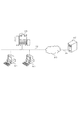
図1は本実施形態における画像形成装置の一例であるMFP(マルチ・ファンクション・ペリフェラル)を含むシステム構成の一例を示した図である。
<System configuration>
FIG. 1 is a diagram showing an example of a system configuration including an MFP (multifunction peripheral) which is an example of an image forming apparatus according to the present embodiment.
MFP101はコピー、スキャナ、FAX、プリンタなどの機能を備えた複合画像形成装置である。クライアントPC102および103はMFP101にプリントジョブを送信したり、MFP101からスキャンデータを受信することができる。LAN(ローカル・エリア・ネットワーク)104は、MFP101、クライアントPC102および103を相互に接続するネットワークである。LAN104は、たとえばEthernet(登録商標)などの方式であり、MFP101、クライアントPC102および103や、インターネット網105を通して他のLANに接続された装置とデータを送受信できる。認証サーバ107はMFP101を使用するユーザを認証するためのサーバであり、LAN106とインターネット網105を通してMFP101とデータの送受信を行う。MFP101から認証サーバ107にユーザ情報(例えば、ユーザコードなど)が送信され、認証サーバ107に格納された認証情報と照合することで認証が行われる。認証結果は認証サーバ107からMFP101に送信される。MFP101がユーザ情報を得る方法としては、MFP101に備わるボタンから入力する方法やIDカード読み取り装置を介してユーザが所持しているIDカードから入力する方法がある。なお、認証サーバ107は、LAN106ではなくLAN104に接続されていてもよいものとする。
The MFP 101 is a composite image forming apparatus having functions such as a copy, a scanner, a FAX, and a printer. The
<MFPの外観>
図2はMFPの外観の一例を示した図である。原稿読取部202は原稿を光学的に読み取って原稿の画像データを生成する。給紙部206は用紙を収納するユニットであり、ユーザは用紙を追加することができる。プリンタ部205は用紙に画像を印字するユニットであり、印字の際には給紙部206から搬送された紙にトナー像を載せて定着器を用いて定着させる。印字された紙は排紙部201に排紙される。操作部204はユーザが装置に指示を与えるためのボタンと、装置の状況や操作メニューを表示する液晶などの表示素子からなるユニットである。なお、タッチパネルによって操作部204を構成してもよい。カードリーダ部203はユーザの所持するIDカード内に格納されている情報を読み出す装置である。カードリーダ部203は、カードに対してデータを書き込む機能を備えていてもよいものとする。
<Appearance of MFP>
FIG. 2 is a diagram showing an example of the appearance of the MFP. A
<MFPのハードウェア構成>
図3はMFP内部のハードウェア構成の一例を示したブロック図である。プラグ301は商用交流電源のコンセントに差し込むものであり、電源部302に交流電源を供給する。電源部302は装置内の各ユニットに電力を供給するものである。電源部302は、商用交流電源から得た交流電力の電圧を各ユニットに適した電圧に変換し、電力供給先のユニットによっては必要に応じて交流から直流に変換する。電源部302の内部には、ヒューズ210、リレー212が備えられている。ヒューズ210は、電源部302内に過電流や短絡電流が流れたときに、内部の可溶体が溶断あるいは遮断することで電源部302或いは電源部302が電力を供給するMFP101の各ユニットを保護する。リレー212は、電源部302からMFP101内部の各ユニットへの電力の供給を行ったり停止するためのスイッチングの役割を果たす。ヒューズ210、リレー212はともに電源が投入される回数に依存した寿命があるデバイスである。制御部303はMFP101内の各のユニットの制御を行ったり、電子データの加工や転送に関する制御を行うユニットである。電源制御信号線304は制御部303が電源部302の出力のOn/Offに関する制御を行うための信号である電源制御信号が伝達する信号線である。
<Hardware configuration of MFP>
FIG. 3 is a block diagram showing an example of the hardware configuration inside the MFP. The plug 301 is inserted into a commercial AC power outlet and supplies AC power to the
MFP101は、MFP101を構成する各ユニットに電力を供給する通常の動作モードと、一部のユニットに対して電力を供給しないことで消費電力を低減する省エネモード(省エネルギーモード。省電力モードや、スリープモードなどとも言う)とがある。 The MFP 101 has a normal operation mode in which power is supplied to each unit constituting the MFP 101, and an energy saving mode in which power consumption is reduced by not supplying power to some units (energy saving mode. Power saving mode and sleep mode). Mode).
本実施形態のMFP101は、省エネモードでは消費電力を低減させるために、原稿読取部202、排紙部201、プリンタ部205、給紙部206の電力を切断する。また、制御部303と操作部204については一部に対してのみ電力を供給し、他の部分の電力を切断する。省エネモードにおいて、制御部303内で電力が供給される箇所は、省エネモードから通常モードへ復帰するトリガを検知する回路である。トリガはIDカードの挿入の検出、FAX受信の検出、ネットワークを経由して受信した印刷ジョブの検出、操作部204のボタン操作の検出などである。
In the energy saving mode, the MFP 101 according to the present embodiment cuts off the power of the
MFP101が省エネモードにある場合、MFP101を使用するためにIDカードを読み込ませるユーザや操作部204のボタンを操作するユーザにとっては、できるだけ早く操作部204が使用可能とするのが望ましい。しかしながら、操作部204を制御しているソフトウェアやハードウェアによっては操作部204が使用可能になるまで数秒から数十秒要する場合もある。また、たとえばリレーやヒューズやHDDなどには電源投入の回数に依存した寿命がある(少ない例では数万回)。たとえば、リレーの場合は接点の寿命であり、HDDの場合には記録媒体やヘッドに対する機械的なストレスの蓄積による寿命である。ヒューズの場合には電源が投入される毎に発生する突入電流によって劣化する可溶体の寿命である。したがって、省エネモードと通常モードとを移行する回数には制限がある。したがって、移行回数もできるだけ少ないことが望ましい。なお、リレーは電源部302の内部で使用されている。
When the
<制御部のハードウェア構成>
図4は制御部303のハードウェア構成の一例を示したブロック図である。
<Hardware configuration of control unit>
FIG. 4 is a block diagram illustrating an example of a hardware configuration of the
CPU402は制御部303における処理を実行する。CPU402はメモリ403にロードされたプログラムを実行する。
The
内部バス405はCPU402が制御部303内の各ブロックと通信するためのバスである。
An
ハードディスク(HDD)409は、CPU402が実行するプログラム(OSやアプリケーションプログラムなど)が格納されている。また、HDD409は、ジョブデータや画像データを格納する。ジョブデータとは、例えば、クライアントPC102、103からLAN I/F407を介して受信する印刷処理のためのPDLデータなど、MFPが機能を実行するためのデータのことを指す。なお、HDD409は電力を投入される回数に依存した寿命があるデバイスの一例である。
A hard disk (HDD) 409 stores programs executed by the CPU 402 (such as an OS and application programs). The
リーダI/F404は原稿読取部202と通信してコマンド/ステータスや画像データを授受するためのI/Fである。プリンタI/F410はプリンタ部205と通信してコマンド/ステータスや画像データを授受するI/Fである。FAX I/F408は公衆電話回線に接続され、FAX画像の通信を行うI/Fである。LAN I/F407はEthernet(登録商標)などのネットワークに接続され、ジョブデータやコマンド/ステータスの授受を行う。
A reader I /
操作部I/F406は操作部204との通信を行うI/Fであり、表示部504に表示するデータの送信と、ボタンやタッチパネルなどのユーザからの入力情報の受信を行う。電源制御部401はMFP101の通常モードと省エネモードとの移行を制御するブロックである。CPU402からのコマンドによって通常モードから省エネモードに移行するよう電源制御信号線304を介して電源部302に伝達される電源制御信号を送信或いは変化させる。また、省エネモード下では操作部I/F406、LAN I/F407、FAX I/F408から起動信号線(412、414、416)を介して伝達される起動信号を監視する。変化があった場合に省エネモードから通常モードに復帰するよう電源制御信号を送信或いは変化させる。電源部302は、電源制御信号に応じてMFP101を構成するユニットへの電力を供給/停止する。
An operation unit I /
<操作部のハードウェア構成>
図5は操作部204のハードウェア構成の一例を示したブロック図である。CPU503はメモリ507をワーク領域として利用してプログラムを実行して操作部204全体を制御する。
<Hardware configuration of operation unit>
FIG. 5 is a block diagram illustrating an example of a hardware configuration of the
メモリ507は不揮発のプログラムメモリと書き換え可能な一時メモリとを含む記憶部として構成される。プログラムメモリはCPU503が実行するプログラムを格納する。書き換え可能な一時メモリはCPU503のワーク領域として使用される。
The
表示部504はホストI/F508を経由して制御部303から受信したデータを表示部504内に備える液晶(LCD)に表示する。ボタン部506は押しボタン、或いは表示部504のLCDに重ねたタッチパネルからなる。CPU503はボタン部506の操作(押下)を検知すると、ボタンの押下を検知したこと、あるいはどのボタンが押下されたかを示す情報をホストI/F508を経由して制御部303に送信する。
The
カードリーダ部203はカードリーダI/F502と接続される。カードリーダ部203はCPU503が制御し、カード(IDカードなど)501とのデータの送受信を行う。
The
操作部204内の各ブロックは内部バス505に接続される。
Each block in the
省エネモードにおいては、CPU503は、電源部302から操作部204に供給された電力を、消費電力の低減のために表示部504へは供給しない。或いは、表示部504の液晶のバックライトを消灯するように制御する。また、本実施形態ではCPU503の処理能力やメモリ507のメモリ容量は消費電力の低減のために制限されたスペックとなっている。
In the energy saving mode, the
<カードリーダ部のハードウェア構成>
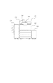
図6は媒体情報読取手段の一例であるカードリーダ部203のハードウェア構成の一例を示したブロック図である。制御部603は操作部204のCPU503の制御に基づき、送信部602、受信部604、アンテナ601を制御し、操作部204とのデータの送受信を行う。
<Hardware configuration of card reader unit>
FIG. 6 is a block diagram showing an example of a hardware configuration of a
送信部602は送信データをアンテナ601に適した信号に変換する。受信部604はアンテナ601が出力した信号を受信データに変換する。アンテナ601は送信部から入力された信号を電磁波に変換する。また、カード501が電池を内蔵していない非接触型カードの場合、アンテナ601はカード501への電力を供給するための磁界を発生する役割もある。またアンテナ601はカード501が出力した電磁波を信号に変換し、受信部604に出力する。
The
本実施形態のカードリーダ部203は、非接触式のICカードを読み取るカードリーダとするが、接触式のICカードを読み取るカードリーダや、磁気記録式のカードリーダなどでもよい。
The
<IDカードのハードウェア構成>
図7はIDカード(以下、単にカードとも呼ぶ)501のハードウェア構成を示したブロック図である。
<Hardware configuration of ID card>
FIG. 7 is a block diagram showing a hardware configuration of an ID card (hereinafter also simply referred to as a card) 501.
CPU701はカードの内部の制御およびカードリーダ部203との通信を行う。カードリーダ部203からデータを受信する場合は、CPU701の制御によって、コマンドの解析および受信データのメモリ705への格納を行う。カードリーダ部203へデータを送信する場合は、CPU701の制御によって、受信したコマンドの内容に応じてメモリ705に格納されているデータを送信部602に転送を行う。
The
メモリ705は書き換え可能な不揮発性メモリであり、CPU701のプログラムコードとユーザ情報やカード情報などが格納されている。
A memory 705 is a rewritable nonvolatile memory, and stores a program code of the
送信部702は送信データをアンテナ704に適した信号に変換する。アンテナ704は送信部から入力された信号を電磁波に変換する。またアンテナ704はカードリーダ部203が送信した電磁波を受信し、受信部703でアンテナ704が出力した信号を受信データに変換する。
The
本実施形態ではカード501が電池を内蔵していない非接触型カードであり、発電部706においてカード501で使用する電力を発電するものとする。カードリーダ部203で発生した磁界はアンテナ704で再び電気エネルギーに変換され、発電部706で直流定電圧に変換する。
In this embodiment, it is assumed that the
<カードに格納されている情報>
図12は本実施形態におけるカード501に格納されているカード情報の一例を示す図である。カードタイプ、カードを製造するベンダー名、カードベンダーが与える固有の番号であるシリアル番号、カードに内蔵されるプログラムのバージョン番号などである。これらの値は、通常はカードがカードベンダーから出荷されるときに書き込まれている。
<Information stored on the card>
FIG. 12 is a diagram showing an example of card information stored in the
図13は本実施形態におけるカード501に格納されているユーザ情報の一例を示す図である。団体コードはユーザの所属する企業や団体を識別するための値である。組織コードはユーザの所属する企業や団体のセクションを識別するための値である。団体コード或いは組織コードを部門コードともいい、部門を特定する部門情報の一例である。個人コードはユーザ個人を識別するためのID値である。これらの値はカードを製造するベンダーが出荷したあと、使用する環境に応じて書き込まれる。
FIG. 13 is a diagram showing an example of user information stored in the
次に、MFPが通常モードから省エネモードへ移行する処理、省エネモードから通常モードへ移行する処理について説明する。 Next, processing for shifting the MFP from the normal mode to the energy saving mode and processing for shifting from the energy saving mode to the normal mode will be described.
<省エネモードへの移行>
図8は、通常モードのMFPが省エネモードへ移行する処理の一例を示すフローチャートである。本フローチャートはMFP101の制御部303が備えるCPU402が実行する。
<Transition to energy saving mode>
FIG. 8 is a flowchart illustrating an example of processing in which the MFP in the normal mode shifts to the energy saving mode. This flowchart is executed by the
MFP101が通常モードで稼動している間に本フローチャートは実行を開始する。まずステップS802で、省エネモードへ移行する要因があるか否かを判定する。本実施形態では、省エネモードへの移行要因は、一定時間操作部204のボタン部506の操作が無かった場合や、予め設定した時刻に達した場合や、ユーザの操作部204の操作による省エネモードへの移行要求などがある。
The flowchart starts executing while the
省エネモードへの移行要因があった場合(ステップS802でYES)、ステップS804へ進み、操作部204に対して省エネモードへの移行通知と第1の認証の条件とを送信する。なお、第1の認証の条件については後に詳述する。
If there is a factor for shifting to the energy saving mode (YES in step S802), the process proceeds to step S804, and a notification of shifting to the energy saving mode and the first authentication condition are transmitted to the
ステップS806においてCPU402は電源制御部401に省エネモード移行命令を発行する。電源制御部401への省エネモード移行命令に基づいて、電源制御部は電源制御信号線304を介して電源部302に対して電源制御信号を送信する。電源部302は、受信した電源制御信号に基づいてMFP101の一部のユニットへの電力供給を停止する。これにより、MFP101は省エネモードに移行して本フローチャートを終了する。
In step S806, the
なお、本実施形態の省エネモード時には、操作部204とカードリーダ部203は電力が供給される。また、制御部303において、操作部I/F406の一部、LANI/F407の一部、FAXI/F408の一部には電力が供給されるがそれ以外の部分については電力供給は停止される。また、原稿読取部202、排紙部201、プリンタ部205、給紙部206への電力供給は停止される。なお、省エネモードは通常モードよりも電力消費量が少ない状態であればよく、どのユニットに対して電力を供給し、どのユニットに対しては電力供給を停止するのかについては本実施形態と異なるものでもよい。
In the energy saving mode of the present embodiment, power is supplied to the
<第1の認証と第2の認証>
ここで本実施形態における第1の認証と第2の認証について説明する。省エネモード中において、IDカードによるユーザ認証の要求があった場合、MFP101はすぐに通常モードには移行せず、操作部204が第1のユーザ認証(以下、第1の認証)を行い、第1の認証が成功した場合にはじめてMFP101は通常モードへ移行する。そして第2のユーザ認証(以下、第2の認証)を実行する。第1の認証が成功しなかった場合にはMFP101は省エネモードを維持し、通常モードへは移行しない。
<First authentication and second authentication>
Here, the first authentication and the second authentication in the present embodiment will be described. When there is a request for user authentication using an ID card in the energy saving mode, the
第1の認証を行うために、予め操作部204のCPU503がメモリ507に認証条件や認証データを格納しておき、カード501から得たカード情報およびユーザ情報と照合することで認証を行う。図8のステップS804では、省エネモード中に操作部204が第1の認証を実行することを可能にするために、制御部303のCPU402は第1の認証を行うための認証条件を操作部204へ通知する。そして、後に説明する図10のフローチャートのステップS1004、S1006では、操作部204は通知された認証条件を記憶する。
In order to perform the first authentication, the
ただし、省エネモードにおける消費電力を低減するために、操作部204のCPU402の処理速度やメモリ507のメモリ容量は限られたものになる。従って、認証サーバ107が備える認証条件および認証許可データ列のすべてをメモリ507に格納することはできないし、また、認証サーバ107が行う認証処理のすべてを操作部204で行なうことはできない。また、省エネモードにおいてはLAN I/F407を介して認証サーバ107とのデータの送受信を行なうこともできないので、通常モードに復帰せずに認証サーバ107を用いた認証処理を行うこともできない。
However, in order to reduce power consumption in the energy saving mode, the processing speed of the
したがって第1の認証では、操作部204のCPU402の処理速度やメモリ507の容量が限られた中で無駄にMFP101を通常モードに移行させないようにすることが可能になる。
Therefore, in the first authentication, it is possible to prevent the
そして、第1の認証が成功した場合にはMFPは通常モードへ移行し、ネットワークを介して認証サーバ107と通信することが可能になったら、認証サーバ107に対してユーザ認証を依頼する。本実施形態ではこれを第2の認証と呼ぶ。
When the first authentication is successful, the MFP shifts to the normal mode, and when it becomes possible to communicate with the
<第1の認証条件と第2の認証条件>
本実施形態では、認証サーバ107が行う認証、つまり第2の認証の条件(条件1)を以下とする。
<First authentication condition and second authentication condition>
In the present embodiment, the authentication performed by the
<条件1>
カードタイプ(カードの種類)がTypeAと等しい
かつ、
団体コードが0033と等しい、
かつ、
個人コードが認証許可データ列と等しい
一方、操作部204が行う第1の認証における条件は、第2の認証の条件を緩和する条件とする。たとえば前述の条件1を緩和する例として、第1の認証のための条件(条件2)は以下のようになる。
<
Card type (card type) is equal to Type A
And,
The organization code is equal to 0033,
And,
On the other hand, the condition for the first authentication performed by the
<条件2>
カードタイプ(カードの種類)がTypeAと等しい
かつ、
団体コードが0033と等しい
条件2で示した条件式では、カードタイプがTypeAと等しいという条件と、団体コードが0033と等しいという条件の2つのAND条件であり、条件1に含まれていた個人コードが認証許可データ列と等しいという条件を省いている。したがって、操作部204のメモリ507には認証を許可する個人コードを表すデータ列を格納する必要がなく、メモリ容量は節約できる。特に、認証を許可するユーザコードを示すデータ列のデータ量が大きいときはより効果的である。異なるタイプのIDカードを使ってユーザ認証を行おうとした場合や、正しい部門コードが記録されていないIDカードを使ってユーザ認証を行おうとした場合には第1の認証に失敗する。そのような場合には省エネモードから通常モードへ移行することがなくなり、無駄な省エネモードからの復帰を防止することができる。
<
Card type (card type) is equal to Type A
And,
The group code is equal to 0033. In the conditional expression shown in
第1の認証が成功した場合は、MFP101が省エネモードから通常モードに復帰し、制御部303における第2の認証を行う。第2の認証の処理については後述する。
When the first authentication is successful, the
<省エネモードからの復帰>
図9は、MFPの省エネモードからの復帰およびユーザ認証の処理の一例を示すフローチャートである。本フローチャートはMFP101の制御部303が備えるCPU402が実行する。
<Return from energy-saving mode>
FIG. 9 is a flowchart illustrating an example of processing for returning from the energy saving mode of the MFP and user authentication. This flowchart is executed by the
操作部204から省エネモードからの復帰要求を受け付けたことに基づいて本フローチャートの処理が開始される。復帰要求は、操作部204のホストI/F、制御部303の操作部I/F406を介して電源制御部401へ通知される。そして、電源制御部401が制御部303へ電力を供給することで制御部303内の各デバイスが起動を開始し、CPU402は本フローチャートの実行を開始する。なお、操作部204が制御部303に復帰要求を発行するまでの処理については後述する。
The processing of this flowchart is started when a return request from the energy saving mode is received from the
ステップS902においてCPU402は制御部303内部や外部の各ユニットを初期化してMFP101を通常モードへ移行させる。省エネモードから通常モードへの移行によって起動回数に上限のある部品の寿命が1回分消費されることになる。
In step S <b> 902, the
そして、操作部204に対してカード501に格納されているカード情報およびユーザ情報を要求し(ステップS904)、当該要求に応答して操作部204から送信されるカード情報およびユーザ情報を受信する(ステップS906)。
Then, the card information and user information stored in the
そして、ステップS908において認証サーバ107に対してカード情報およびユーザ情報を送信してユーザ認証を依頼する。認証サーバ107ではMFP101から送信されたカード情報およびユーザ情報を認証サーバに格納されている認証条件や認証データと照合して認証処理を行い、ユーザ認証が成功したか失敗したかを判定し、判定結果をMFP101へ返送する。ステップS908におけるMFP101の処理、及び認証サーバ107における認証処理が本実施形態における第2の認証に相当する。認証サーバ107は、上述の条件1に基づいて認証の成否を判定する。
In step S908, the card information and user information are transmitted to the
ステップS910では、認証サーバから返送されたユーザ認証の結果を検証し、認証結果が成功であれば、ステップS912へ進み、失敗であればステップS916へ進む。 In step S910, the user authentication result returned from the authentication server is verified. If the authentication result is successful, the process proceeds to step S912, and if unsuccessful, the process proceeds to step S916.
ステップS912では操作部204に対してユーザ認証が成功したことを通知しユーザ認証が成功したことを操作部204の表示部504に表示させる。そして、ステップS914において操作部204の表示部504に通常の操作メニューを表示させ、ユーザがMFP101を操作可能な状態にして本フローチャートを終了する。
In step S912, the
一方、ステップS910において認証結果が失敗であれば、ステップS916においてユーザ認証が失敗したことを操作部204へ通しし、ユーザ認証が失敗であることを操作部204の表示部504に表示させる。そして、MFP101を再び省エネモードへ移行させて本フローチャートを終了する。
On the other hand, if the authentication result is unsuccessful in step S910, the fact that the user authentication has failed in step S916 is passed to the
<省エネモード移行時の操作部の処理>
図10は、MFPが省エネモードに移行する場合の操作部の処理の一例を示すフローチャートである。本フローチャートは操作部204のCPU503が実行する。MFP101が通常モードにある間に本フローチャートは実行を開始する。
<Processing of the operation unit when shifting to energy saving mode>
FIG. 10 is a flowchart illustrating an example of processing performed by the operation unit when the MFP shifts to the energy saving mode. This flowchart is executed by the
ステップS1002では制御部303からの通知を待機する。制御部303からの通知があればステップS1004へ進み、CPU503は制御部303からホストI/F508を介して第一の認証条件と省エネモードへの移行通知を受信する。なお、当該通知は図8のフローチャートのステップS804において制御部303から送信されたものである。
In step S1002, a notification from the
そしてステップS1006で、受信した第1の認証条件をメモリ507に格納する。そして、ステップS1008で表示部504の液晶のバックライトを消灯して本フローチャートを終了する。なお、本フローチャートの処理と並行して、MFP101も通常モードから省エネモードへ移行することになる。
In step S1006, the received first authentication condition is stored in the
<操作部からの復帰要求>
図11は、省エネモード下の操作部における省エネモードからの復帰要求の送信および第1の認証処理の一例を示すフローチャートである。
<Return request from the operation unit>
FIG. 11 is a flowchart illustrating an example of transmission of a return request from the energy saving mode and first authentication processing in the operation unit under the energy saving mode.
図10のフローチャートを実行した後の状態において本フローチャートの実行を開始する。 The execution of this flowchart is started in a state after the flowchart of FIG. 10 is executed.
ステップS1102において、CPU503はカード501を検知したか否かを判定する。カードリーダ部203のアンテナ601に電力を供給して、付近にカード501があればカード501に対してレスポンスを要求するコマンドを発行する。もしレスポンスが得られなければ、カード501を検知できなかったと判断し、レスポンスが得られた場合は、カード501を検知できたと判断する。CPU503は、カード501を検知したことで、カードによるユーザ認証の要求があったものと判断する。
In step S1102, the
認証要求があると判断したCPU503は、ステップS1104においてカード501に対してカード情報およびユーザ情報の送信命令を発行し、その応答としてカード501から送信されるカード情報とユーザ情報を読み取る。そして、ステップS1106においてカード情報およびユーザ情報を読み取ることができたか否かを判定する。カードからの情報の読みとりに成功したと判定した場合にはステップS1108へ進み、失敗したと判定した場合にはステップS1102に戻る。
The
ステップS1108では、第1の認証を行う。具体的には、ステップS1104で読み取ったカード情報およびユーザ情報と、図10ステップS1004でメモリ507に記憶したされた第一の認証条件とを照合する。そして、ステップS1110において、第1の認証が成功したか否かを決定する。成功したと決定した場合にはステップS1112に進み、失敗したと決定した場合にはステップS1102に戻る。
In step S1108, first authentication is performed. Specifically, the card information and user information read in step S1104 are collated with the first authentication condition stored in the
ステップS1112では、制御部303に省エネモードから通常モードへ移行(復帰)することを要求する復帰要求信号を送信する。これにより制御部303の電源制御部401に要求信号が伝達され、図9のフローチャートが実行されることにより、MFP101が通常状態へ移行する処理を実行する。
In step S1112, a return request signal for requesting the
MFP101が通常状態に移行すると、図9のステップS904の処理によって、制御部303からカード情報とユーザ情報が要求される。当該要求を受け付けたら(ステップS1114でYES)ステップS1116へ遷移し、ステップS1104で読み取ったカード情報とユーザ情報を制御部303に送信する。
When the
以上説明したように、省エネモード下において操作部204で検知したカード501に対して第1の認証が成功したことを条件にMFP101は省エネモードから通常モードへ移行する。これにより、例えば、誤ったカードをカードリーダ部203にかざしてしまったことによってMFP101が誤って省エネモードから復帰することを防ぐことができる。よって、不必要な省エネモードからの復帰による無駄な電力消費を防止し、起動回数に上限のある部品の寿命が短くなることを防止することができる。
As described above, the
<第1の認証における他の条件例>
本実施形態においては、第1の認証のための条件である条件2を、第2の認証のための条件である条件1から「個人コードが認証許可データ列と等しい」という条件を削除するものとした。条件2はそれ以外の条件を設定することも考えられる。以下、条件2の他のバリエーションについて説明する。なお、認証サーバ107での認証条件である条件1は上述のとおりであるものとする。
<Other condition examples in the first authentication>
In the present embodiment, the
第1の認証のための他の条件(条件3)として、以下を例示する。 The following is exemplified as another condition (condition 3) for the first authentication.
<条件3>
カードタイプ(カードの種類)がTypeAと等しい
かつ、
団体コードが0033と等しい、
かつ、
個人コードは00000111より大きい
かつ、
個人コードは00011240より小さい
条件3によれば、条件2に比べて、更に個人コードがある範囲内の値であるかをチェックする分だけ条件が厳しくなっている。個人コードがある範囲の値であるかを条件にすれば、メモリ507の消費量は小さくすることができる。ただし、個人コードが00000113、00000114などの図14の認証許可データ列に含まれない個人コードに対しても第1の認証がOKとなるが、これらの個人コードをもつカードについては第2の認証で認証NGとなる。
<
Card type (card type) is equal to Type A
And,
The organization code is equal to 0033,
And,
Personal code is greater than 00000111
And,
The personal code is smaller than 00011240 According to
第1の認証のための他の条件(条件4)として、以下を例示する。 The following is exemplified as another condition (condition 4) for the first authentication.
<条件4>
カードタイプ(カードの種類)がTypeAと等しい
かつ、
団体コードが0033と等しい、
かつ、
個人コードが認証不可データ列と等しくない
条件4は、認証許可データ列に含まれない認証データの一部を認証不可データ列としてメモリ507保持することによって実現できる。認証不可データ列は、たとえば、図14に示したような認証許可データ列に含まれない値からなるデータ列である。図15に認証不可データ列の例を示す。認証不可のデータ数が少ない場合にこの方法がメモリ507の使用量の削減に効果がある。
<
Card type (card type) is equal to Type A
And,
The organization code is equal to 0033,
And,
The personal code is not equal to the unauthenticable
認証不可データ列は、認証許可データ列に含まれないすべての値を持たなくてもよい。認証サーバ107で使用する認証許可データ列にも、第1の認証手段で使用する認証不可データ列にも含まれない値をもつカードを検出した場合には第1の認証手段はOKとなり、第2の認証手段でNGと判断される。
The unauthenticable data string may not have all values not included in the authentication permission data string. When a card having a value not included in the authentication permission data string used in the
なお、条件4で説明した認証不可データ列は固定的なデータでなくてもよく、過去のユーザ認証の結果に基づいて動的に変更するようにしてもよい。以下、認証不可データを過去のユーザ認証の結果に基づいて動的に生成する例について説明する。
Note that the unauthenticated data string described in
図16は本実施形態における第1の認証条件の生成に使用する認証結果の履歴の一例である。これは、第二の認証の際に制御部303のCPU402が、認証結果をHDD409に格納されている履歴ファイルに追加することで履歴が蓄積される。ここで認証に失敗(NG)であった例は4件(番号:4、6、8、12のレコード)であり、うち3件(番号:4、6、12のレコード)が個人コードの不一致である。
FIG. 16 is an example of an authentication result history used to generate the first authentication condition in the present embodiment. This is because the history is accumulated by the
図17は本実施形態における第一の認証条件に含まれる認証不可データ列の例である。ここでは、履歴にある認証NGであったユーザコードのみから構成されている。過去に認証NGになったユーザは、MFP101の近傍にいる確率が高いため、再度認証を試みる可能性も高く、認証NGの検出率の向上することが可能となる。また、履歴には通常モード下における認証結果も追加してもよい。履歴の数が多いほど、認証NGの検出率を向上させることができる。
FIG. 17 is an example of an unauthenticated data string included in the first authentication condition in the present embodiment. Here, it is comprised only from the user code which was the authentication NG in the history. Since the user who has been authenticated NG in the past has a high probability of being in the vicinity of the
過去の認証結果の履歴を利用することで認証不可データ列を少ない容量に抑えながら、より第1の認証において認証が失敗するカードの検出率を向上させることができる。 By using the history of past authentication results, it is possible to improve the detection rate of cards that fail authentication in the first authentication while suppressing the unauthenticated data string to a small capacity.
なお、本実施形態では、画像形成装置の一例として複合画像形成装置であるMFPを挙げて説明したが、単機能の画像形成装置(複写機、ファクシミリ装置、プリンタ、等)においても適用することができる。 また、本実施形態ではカード501として、電池を内蔵していない非接触型のICカードを用いることを前提としたが、電池を内蔵した非接触型のICカードを用いてもよい。また、接触型のICカードを用いてもよい。その場合はカードリーダ203は接触型のICカードリーダを用いることになる。また、MFP101は認証サーバ107を用いずに、MFP101自身で第2の認証を行うようにしてもよい。その場合は、認証サーバ107がユーザ認証を行うための機能やデータを制御部303内に備えるようにすることで実現することができる。
In the present embodiment, the MFP which is a composite image forming apparatus has been described as an example of the image forming apparatus. However, the present invention can also be applied to a single-function image forming apparatus (copying machine, facsimile apparatus, printer, etc.). it can. In this embodiment, it is assumed that a non-contact type IC card without a battery is used as the
以上説明したように、本実施形態によれば、過去の認証結果の履歴を利用することで、メモリ507に格納する認証不可データ列を少ない容量に抑えながら、第一の認証手段において認証NGのカードの検出率を向上させることができる。その結果、省エネモード中のMFP101は不必要に通常モードへ復帰する回数を減らすことができ、MFP101が無駄に電力を消費することを防止し、起動回数に上限のある部品の寿命が短くなることを防止することができる。
As described above, according to the present embodiment, by using the history of past authentication results, the authentication unit NG of the authentication NG is suppressed in the first authentication unit while suppressing the unauthenticated data string stored in the
〔他の実施形態〕
本発明は、前述した実施形態の各機能を実現するための制御プログラムを、システム若しくは装置に対して直接または遠隔から供給し、そのシステム等に含まれるコンピュータが該供給されたプログラムコードを読み出して実行することによっても達成される。
[Other Embodiments]
The present invention supplies a control program for realizing each function of the above-described embodiment directly or remotely to a system or apparatus, and a computer included in the system reads the supplied program code. It is also achieved by executing.
従って、本発明の機能・処理をコンピュータや上述の装置で実現するために、該コンピュータや上述の装置にインストールされる制御プログラムのプログラムコード自体も本発明を実現するものである。つまり、上記機能・処理を実現するための制御プログラム自体も本発明の一つである。 Accordingly, since the functions and processes of the present invention are implemented by a computer or the above-described apparatus, the program code itself of the control program installed in the computer or the above-described apparatus also implements the present invention. That is, the control program itself for realizing the functions and processes is also one aspect of the present invention.
その場合、プログラムの機能を有していれば、オブジェクトコード、インタプリタにより実行されるプログラム、OSに供給するスクリプトデータ等、プログラムの形態を問わない。 In this case, the program may be in any form as long as it has a program function, such as an object code, a program executed by an interpreter, or script data supplied to the OS.
プログラムを供給するための記録媒体としては、例えば、フレキシブルディスク、ハードディスク、光ディスク、光磁気ディスク、MO、CD−ROM、CD−R、CD−RWなどがある。また、記録媒体としては、磁気テープ、不揮発性のメモリカード、ROM、DVD(DVD−ROM、DVD−R)、USBメモリなどもある。 Examples of the recording medium for supplying the program include a flexible disk, hard disk, optical disk, magneto-optical disk, MO, CD-ROM, CD-R, and CD-RW. Examples of the recording medium include a magnetic tape, a non-volatile memory card, a ROM, a DVD (DVD-ROM, DVD-R), and a USB memory.
また、プログラムは、クライアントコンピュータのブラウザを用いてインターネット/イントラネットのウェブサイトやファイルサーバからダウンロードしてもよい。すなわち、該ウェブサイトから本発明のコンピュータプログラムそのもの、もしくは圧縮され自動インストール機能を含むファイルをハードディスク等の記録媒体にダウンロードしてもよいのである。また、本発明のプログラムを構成するプログラムコードを複数のファイルに分割し、それぞれのファイルを異なるウェブサイトからダウンロードすることによっても実現可能である。つまり、本発明の機能処理をコンピュータで実現するためのプログラムファイルを複数のユーザに対してダウンロードさせるWWWサーバも、本発明の構成要件となる場合がある。 The program may be downloaded from an Internet / intranet website or a file server using a browser of a client computer. That is, the computer program itself of the present invention or a compressed file including an automatic installation function may be downloaded from the website onto a recording medium such as a hard disk. It can also be realized by dividing the program code constituting the program of the present invention into a plurality of files and downloading each file from a different website. That is, a WWW server that allows a plurality of users to download a program file for realizing the functional processing of the present invention on a computer may be a constituent requirement of the present invention.
また、本発明のプログラムを暗号化してCD−ROM等の記憶媒体に格納してユーザに配布してもよい。この場合、所定条件をクリアしたユーザにのみ、インターネット/イントラネットを介してウェブサイトから暗号化を解く鍵情報をダウンロードさせ、その鍵情報で暗号化されたプログラムを復号して実行し、プログラムをコンピュータにインストールしてもよい。 Further, the program of the present invention may be encrypted and stored in a storage medium such as a CD-ROM and distributed to users. In this case, only the user who has cleared the predetermined condition is allowed to download the key information to be decrypted from the website via the Internet / intranet, decrypt the program encrypted with the key information, and execute the program. You may install it on
また、コンピュータが、読み出したプログラムを実行することによって、前述した実施形態の機能が実現されてもよい。なお、そのプログラムの指示に基づき、コンピュータ上で稼動しているOSなどが、実際の処理の一部または全部を行ってもよい。もちろん、この場合も、前述した実施形態の機能が実現され得る。 Further, the functions of the above-described embodiments may be realized by the computer executing the read program. Note that an OS or the like running on the computer may perform part or all of the actual processing based on the instructions of the program. Of course, also in this case, the functions of the above-described embodiments can be realized.
さらに、記録媒体から読み出されたプログラムが、コンピュータに挿入された機能拡張ボードやコンピュータに接続された機能拡張ユニットに備わるメモリに書き込まれてもよい。そのプログラムの指示に基づき、その機能拡張ボードや機能拡張ユニットに備わるCPUなどが実際の処理の一部または全部を行ってもよい。このようにして、前述した実施形態の機能が実現されることもある。 Furthermore, the program read from the recording medium may be written in a memory provided in a function expansion board inserted into the computer or a function expansion unit connected to the computer. Based on the instructions of the program, a CPU or the like provided in the function expansion board or function expansion unit may perform part or all of the actual processing. In this way, the functions of the above-described embodiments may be realized.
101 MFP
102、103 クライアントPC
104、106 LAN
105 インターネット網
107 認証サーバ
201 排紙部
202 原稿読取部
203 カードリーダ部
204 操作部
205 プリンタ部
206 給紙部
302 電源部
303 制御部
101 MFP
102, 103 Client PC
104, 106 LAN
DESCRIPTION OF
Claims (15)
前記複数のユニットに対して電力を供給することが可能であり、前記複数のユニットに対して電力を供給するモードとして、第1の電力モードと第1の電力モードよりも供給する電力が小さい第2の電力モードとを備える電力供給手段と、
前記電力供給手段に対して電力を供給するモードを指示する制御手段と、
前記第2の電力モードにおいて前記電力供給手段から電力が供給され、認証情報を格納した記憶媒体から情報を読み取る読み取り手段と、
前記第2の電力モードにおいて前記読み取り手段が読み取った情報に基づいて、前記認証情報を認証するための処理を実行するか否かを決定する決定手段と、を備え、
前記制御手段は、前記決定手段が前記認証情報を認証するための処理を実行すると決定したことに従って、前記電力供給手段に対して前記第2の電力モードから前記第1の電力モードへ移行するよう指示することを特徴とする画像形成装置。 An image forming apparatus including a plurality of units,
It is possible to supply power to the plurality of units, and a mode in which power is supplied to the plurality of units is smaller than the first power mode and the first power mode. Power supply means comprising two power modes;
Control means for instructing a mode for supplying power to the power supply means;
Reading means for reading the second power from the previous SL power supply means Te power mode odor is supplied, the information from the storage medium storing the authentication information,
Determining means for deciding whether or not to execute processing for authenticating the authentication information based on information read by the reading means in the second power mode;
The control means shifts the power supply means from the second power mode to the first power mode according to the determination means determining to execute the process for authenticating the authentication information. An image forming apparatus characterized by instructing.
前記制御手段は、前記電力供給手段に対して前記第2の電力モードから前記第1の電力モードに移行するよう指示した後に、前記外部の認証装置に対して前記読み取り手段が読み取った前記認証情報に基づいてユーザ認証を行わせることを特徴とする、請求項1に記載の画像形成装置。 The image forming apparatus can communicate with an external authentication apparatus via a network,
The control means, after instructing the power supply means to shift from the second power mode to the first power mode, the authentication information read by the reading means to the external authentication device The image forming apparatus according to claim 1, wherein user authentication is performed based on the image data.
前記操作部は前記決定手段を備えることを特徴とする、請求項1に記載の画像形成装置。 An operation unit that receives an operation on the image forming apparatus by a user;
The image forming apparatus according to claim 1, wherein the operation unit includes the determination unit .
前記第2の電力モードにおいて前記電力供給手段から電力が供給され、認証情報を格納した記憶媒体から情報を読み取る読み取り工程と、
前記読み取り工程で読み取られた情報に基づいて、前記認証情報を認証するための処理を実行するか否かを決定する決定工程と、
前記決定工程において前記認証情報を認証するための処理を実行すると決定されたことに従って、前記電力供給手段に対して前記第2の電力モードから前記第1の電力モードへ移行するよう指示する指示工程と、を有することを特徴とする画像形成装置の制御方法。 It is possible to supply power to a plurality of units and the plurality of units, and supply power to the plurality of units as compared to the first power mode and the first power mode. An image forming apparatus control method comprising: a power supply unit including a second power mode with a small amount of power to perform; and a control unit that instructs a mode for supplying power to the power supply unit.
A reading step for reading the information from the second power from the previous SL power supply means Te power mode odor is supplied, the storage medium storing the authentication information,
A determination step for determining whether to execute a process for authenticating the authentication information based on the information read in the reading step;
An instruction step for instructing the power supply means to shift from the second power mode to the first power mode when it is determined to execute the process for authenticating the authentication information in the determining step. And a method for controlling the image forming apparatus.
前記第2の電力モードにおいて前記電力供給手段から電力が供給され、認証情報を格納した記憶媒体から情報を読み取る読み取り工程と、
前記読み取り工程で読み取られた情報に基づいて、前記認証情報を認証するための処理を実行するか否かを決定する決定工程と、
前記決定工程において前記認証情報を認証するための処理を実行すると決定されたことに従って、前記電力供給手段に対して前記第2の電力モードから前記第1の電力モードへ移行するよう指示する指示工程と、を備えることを特徴とする制御プログラム。 It is possible to supply power to a plurality of units and the plurality of units, and supply power to the plurality of units as compared to the first power mode and the first power mode. Control for causing an image forming apparatus to execute a control method, comprising: a power supply unit including a second power mode with a small amount of power to be performed; and a control unit that instructs a mode for supplying power to the power supply unit. A program, the control method comprising:
A reading step for reading the information from the second power from the previous SL power supply means Te power mode odor is supplied, the storage medium storing the authentication information,
A determination step for determining whether to execute a process for authenticating the authentication information based on the information read in the reading step;
An instruction step for instructing the power supply means to shift from the second power mode to the first power mode when it is determined to execute the process for authenticating the authentication information in the determining step. And a control program comprising:
Priority Applications (3)
| Application Number | Priority Date | Filing Date | Title |
|---|---|---|---|
| JP2008301216A JP5164810B2 (en) | 2008-11-26 | 2008-11-26 | Image forming apparatus and image forming apparatus control method |
| US12/624,033 US8322609B2 (en) | 2008-11-26 | 2009-11-23 | Image forming apparatus and control method of image forming apparatus |
| US13/664,918 US8528815B2 (en) | 2008-11-26 | 2012-10-31 | Image forming apparatus and control method of image forming apparatus |
Applications Claiming Priority (1)
| Application Number | Priority Date | Filing Date | Title |
|---|---|---|---|
| JP2008301216A JP5164810B2 (en) | 2008-11-26 | 2008-11-26 | Image forming apparatus and image forming apparatus control method |
Related Child Applications (1)
| Application Number | Title | Priority Date | Filing Date |
|---|---|---|---|
| JP2012271913A Division JP5342061B2 (en) | 2012-12-13 | 2012-12-13 | Image forming apparatus and image forming apparatus control method |
Publications (3)
| Publication Number | Publication Date |
|---|---|
| JP2010128090A JP2010128090A (en) | 2010-06-10 |
| JP2010128090A5 JP2010128090A5 (en) | 2012-01-19 |
| JP5164810B2 true JP5164810B2 (en) | 2013-03-21 |
Family
ID=42195314
Family Applications (1)
| Application Number | Title | Priority Date | Filing Date |
|---|---|---|---|
| JP2008301216A Active JP5164810B2 (en) | 2008-11-26 | 2008-11-26 | Image forming apparatus and image forming apparatus control method |
Country Status (2)
| Country | Link |
|---|---|
| US (2) | US8322609B2 (en) |
| JP (1) | JP5164810B2 (en) |
Families Citing this family (16)
| Publication number | Priority date | Publication date | Assignee | Title |
|---|---|---|---|---|
| JP4671140B2 (en) | 2009-02-26 | 2011-04-13 | 富士ゼロックス株式会社 | Information processing apparatus, system, and program |
| JP2011185974A (en) * | 2010-03-04 | 2011-09-22 | Konica Minolta Business Technologies Inc | Image forming apparatus, method and program for controlling the same |
| JP5494301B2 (en) * | 2010-07-07 | 2014-05-14 | コニカミノルタ株式会社 | Image forming apparatus, confidential printing method, and confidential printing program |
| JP5440533B2 (en) * | 2011-03-29 | 2014-03-12 | ブラザー工業株式会社 | Image forming apparatus |
| JP5836013B2 (en) | 2011-08-26 | 2015-12-24 | キヤノン株式会社 | Image processing apparatus, control method thereof, and program |
| US9552037B2 (en) * | 2012-04-23 | 2017-01-24 | Google Inc. | Switching a computing device from a low-power state to a high-power state |
| JP6102087B2 (en) | 2012-06-01 | 2017-03-29 | 株式会社リコー | Image forming apparatus, method, and program |
| JP6171498B2 (en) | 2012-10-09 | 2017-08-02 | 株式会社リコー | Information processing device |
| JP5708671B2 (en) * | 2013-01-21 | 2015-04-30 | コニカミノルタ株式会社 | Power supply control device and power supply control system |
| JP5862642B2 (en) * | 2013-10-30 | 2016-02-16 | ブラザー工業株式会社 | Image recording apparatus and program |
| JP6078453B2 (en) * | 2013-10-31 | 2017-02-08 | 京セラドキュメントソリューションズ株式会社 | Image forming apparatus |
| JP6264896B2 (en) * | 2014-01-16 | 2018-01-24 | 株式会社リコー | Information processing apparatus, control method, and control program |
| JP2016027954A (en) * | 2014-07-10 | 2016-02-25 | 株式会社リコー | Information processing system, information processing method, and program |
| ITUB20152547A1 (en) * | 2015-07-28 | 2017-01-28 | Saipem Spa | BREAKDOWN ASSEMBLY IN A TRINCEA FOR A CONTINUOUS CONDUCT AND METHOD OF BREAKING |
| JP6056951B2 (en) * | 2015-12-24 | 2017-01-11 | ブラザー工業株式会社 | Image recording apparatus and program |
| JP2017185637A (en) * | 2016-04-01 | 2017-10-12 | セイコーエプソン株式会社 | Electronic apparatus and control method |
Family Cites Families (9)
| Publication number | Priority date | Publication date | Assignee | Title |
|---|---|---|---|---|
| US5327497A (en) * | 1992-06-04 | 1994-07-05 | Integrated Technologies Of America, Inc. | Preboot protection of unauthorized use of programs and data with a card reader interface |
| JP4592176B2 (en) * | 2000-11-15 | 2010-12-01 | コニカミノルタビジネステクノロジーズ株式会社 | Image forming apparatus, portable information terminal, communication system, control method for image forming apparatus, control method for portable information terminal, and recording medium on which program for realizing control method is recorded |
| JP4053366B2 (en) * | 2001-08-31 | 2008-02-27 | 株式会社リコー | Electronics |
| JP2005131872A (en) * | 2003-10-29 | 2005-05-26 | Kyocera Mita Corp | Image forming apparatus |
| JP2005342954A (en) * | 2004-06-01 | 2005-12-15 | Matsushita Electric Ind Co Ltd | Multifunction apparatus |
| JP2006005911A (en) * | 2004-05-19 | 2006-01-05 | Ricoh Co Ltd | Image forming apparatus and method of controlling energy saving mode |
| JP4366272B2 (en) | 2004-08-05 | 2009-11-18 | キヤノン株式会社 | Image forming apparatus, control method, and image forming system |
| JP2008023914A (en) * | 2006-07-24 | 2008-02-07 | Sharp Corp | Power supply control method for image forming device, power supply control system for image forming device, power supply control device, image forming device, and computer program |
| US20080197191A1 (en) * | 2007-02-19 | 2008-08-21 | Kabushiki Kaisha Toshiba | Image processing apparatus and method for operating image processing apparatus |
-
2008
- 2008-11-26 JP JP2008301216A patent/JP5164810B2/en active Active
-
2009
- 2009-11-23 US US12/624,033 patent/US8322609B2/en active Active
-
2012
- 2012-10-31 US US13/664,918 patent/US8528815B2/en active Active
Also Published As
| Publication number | Publication date |
|---|---|
| JP2010128090A (en) | 2010-06-10 |
| US8528815B2 (en) | 2013-09-10 |
| US20100127076A1 (en) | 2010-05-27 |
| US20130061075A1 (en) | 2013-03-07 |
| US8322609B2 (en) | 2012-12-04 |
Similar Documents
| Publication | Publication Date | Title |
|---|---|---|
| JP5164810B2 (en) | Image forming apparatus and image forming apparatus control method | |
| JP5342061B2 (en) | Image forming apparatus and image forming apparatus control method | |
| JP5300451B2 (en) | Image processing apparatus and image processing apparatus control method | |
| US11023189B2 (en) | Image processing apparatus, control method for image processing apparatus, and storage medium | |
| JP5813055B2 (en) | Image forming apparatus | |
| JP4820911B1 (en) | Image forming system and image forming apparatus | |
| US10466944B2 (en) | Image forming apparatus, image forming system, and non-transitory storage medium | |
| JP5056283B2 (en) | Printing system | |
| US20090040546A1 (en) | Printer control apparatus and method | |
| JP2007128323A (en) | Information processor, authentication processing method and computer program | |
| JP5440533B2 (en) | Image forming apparatus | |
| JP2010170233A (en) | Image forming system, server device, and image forming device | |
| JP5103307B2 (en) | Image forming apparatus | |
| US8363236B2 (en) | Information processing apparatus, device management method, and computer-readable storage medium | |
| US8131163B2 (en) | Image forming apparatus for performing an MICR printing operation | |
| JP5135238B2 (en) | Image forming system and server device | |
| JP2011068022A (en) | Recording device, control method of recording device and program | |
| JP7134670B2 (en) | IMAGE FORMING APPARATUS AND CONTROL METHOD FOR IMAGE FORMING APPARATUS | |
| JP5097749B2 (en) | Image forming system and server device | |
| JP4380342B2 (en) | Image forming system and image forming apparatus | |
| JP2010102494A (en) | Printer power supply control system and print management device | |
| JP2001320516A (en) | Facsimile equipment, communication system, method for standby control with low power consumption, and storage medium | |
| JP4453359B2 (en) | Image processing apparatus, function management method of image processing apparatus, function management program, and medium | |
| JP5447081B2 (en) | Image forming apparatus and control program therefor | |
| JP2006143436A (en) | Image forming device |
Legal Events
| Date | Code | Title | Description |
|---|---|---|---|
| RD01 | Notification of change of attorney |
Free format text: JAPANESE INTERMEDIATE CODE: A7421 Effective date: 20100630 |
|
| A521 | Request for written amendment filed |
Free format text: JAPANESE INTERMEDIATE CODE: A523 Effective date: 20111125 |
|
| A621 | Written request for application examination |
Free format text: JAPANESE INTERMEDIATE CODE: A621 Effective date: 20111125 |
|
| A977 | Report on retrieval |
Free format text: JAPANESE INTERMEDIATE CODE: A971007 Effective date: 20121112 |
|
| TRDD | Decision of grant or rejection written | ||
| A01 | Written decision to grant a patent or to grant a registration (utility model) |
Free format text: JAPANESE INTERMEDIATE CODE: A01 Effective date: 20121120 |
|
| A61 | First payment of annual fees (during grant procedure) |
Free format text: JAPANESE INTERMEDIATE CODE: A61 Effective date: 20121218 |
|
| FPAY | Renewal fee payment (event date is renewal date of database) |
Free format text: PAYMENT UNTIL: 20151228 Year of fee payment: 3 |
|
| R151 | Written notification of patent or utility model registration |
Ref document number: 5164810 Country of ref document: JP Free format text: JAPANESE INTERMEDIATE CODE: R151 |
|
| FPAY | Renewal fee payment (event date is renewal date of database) |
Free format text: PAYMENT UNTIL: 20151228 Year of fee payment: 3 |