JP5155105B2 - Base station equipment - Google Patents
Base station equipment Download PDFInfo
- Publication number
- JP5155105B2 JP5155105B2 JP2008289883A JP2008289883A JP5155105B2 JP 5155105 B2 JP5155105 B2 JP 5155105B2 JP 2008289883 A JP2008289883 A JP 2008289883A JP 2008289883 A JP2008289883 A JP 2008289883A JP 5155105 B2 JP5155105 B2 JP 5155105B2
- Authority
- JP
- Japan
- Prior art keywords
- base station
- synchronization
- reception
- transmission
- mode
- Prior art date
- Legal status (The legal status is an assumption and is not a legal conclusion. Google has not performed a legal analysis and makes no representation as to the accuracy of the status listed.)
- Expired - Fee Related
Links
Images


Description
本発明は、複数の端末装置を含む無線通信網の末端となる基地局装置に関する。より具体的には、その基地局装置間で行う同期方法と、当該無線通信網を構成する無線通信システムに関する。 The present invention relates to a base station apparatus serving as a terminal of a wireless communication network including a plurality of terminal apparatuses. More specifically, the present invention relates to a synchronization method performed between the base station apparatuses and a radio communication system constituting the radio communication network.
例えば、モバイルWiMAX(Worldwide Interoperability for Microwave Access)のような、移動可能な端末装置(移動端末)が無線通信する無線通信システムにおいては、基地局装置が各地に多数設置される。
上記WiMAXでは、移動端末との間の無線通信方式として、送信と受信とを高速に切り替えるTDD(Time Division Duplex:時分割複信)によるデュプレックス通信方式を採用している。
For example, in a wireless communication system in which mobile terminal devices (mobile terminals) such as mobile WiMAX (Worldwide Interoperability for Microwave Access) communicate wirelessly, a large number of base station devices are installed in various places.
The WiMAX employs a TDD (Time Division Duplex) duplex communication system that switches between transmission and reception at high speed as a wireless communication system with a mobile terminal.
具体的には、図10に示すように、下りサブフレーム(基地局装置の送信フレーム)DLと上りサブフレーム(移動端末の送信フレーム)ULとからなる1つの基本フレームが時間方向に並べて配置されていて、下りサブフレームDLの先頭部分にはプリアンブル(Preamble)が設けられている。
図10では、複数の基地局装置同士で、送信タイミング及び受信タイミングが一致しており、基地局間のフレーム同期(以下、「同期」はフレームタイミングの同期を意味する。)がとれている様子を示している。かかる同期処理は、通常、一方の基地局装置の起動時に行われ、他装置との同期がとれてから移動端末との通信が行われる。
Specifically, as shown in FIG. 10, one basic frame composed of a downlink subframe (transmission frame of the base station apparatus) DL and an uplink subframe (transmission frame of the mobile terminal) UL is arranged in the time direction. In addition, a preamble (Preamble) is provided at the head portion of the downlink subframe DL.
In FIG. 10, the transmission timing and the reception timing are the same among a plurality of base station apparatuses, and the frame synchronization between the base stations (hereinafter, “synchronization” means the synchronization of the frame timing). Is shown. Such synchronization processing is normally performed when one of the base station apparatuses is activated, and communication with the mobile terminal is performed after synchronization with the other apparatus.
一方、各基地局装置がカバーする通信エリア(セル)内にある移動端末は、当該セルに対応する基地局装置との間で無線通信を行うことができる。
このため、移動端末が異なるセルに移動すると、移動端末の通信相手となる基地局装置が変更されるが、このとき移動端末は、同時に2つの基地局装置(サービング基地局とターゲット基地局)からの送信信号を受信することになる。
On the other hand, a mobile terminal in a communication area (cell) covered by each base station apparatus can perform wireless communication with the base station apparatus corresponding to the cell.
For this reason, when the mobile terminal moves to a different cell, the base station apparatus with which the mobile terminal communicates is changed. At this time, the mobile terminal simultaneously receives two base station apparatuses (serving base station and target base station). Will be received.
かかる移動端末のセル間移動をスムーズに行うには、セルが隣接する基地局装置間での送信タイミングが揃った状態(図10に示す状態)が確保されている必要がある。この基地局間同期がとれていると、移動端末がセル間を移動する際に2つの基地局装置からの送信信号を確実に受信でき、セル間移動をスムーズに行うことができる。
また、フレームタイミングが同期していないと、第1の基地局装置の送信タイミングが他の第2の基地局装置の受信タイミングと重複することになり、第2の基地局装置において第2の基地局装置からの送信信号が妨害となるが、基地局装置間で同期がとれていると、このような基地局装置間での妨害が発生しない。
そして、上記基地局間同期を行うための技術として、例えば、特許文献1に記載されたGPS衛星からのGPS信号を利用したものが知られている。
If the frame timing is not synchronized, the transmission timing of the first base station device overlaps with the reception timing of the other second base station device, and the second base station device The transmission signal from the station apparatus becomes an obstacle. However, if the base station apparatuses are synchronized, such an interference between the base station apparatuses does not occur.
As a technique for performing synchronization between the base stations, for example, a technique using a GPS signal from a GPS satellite described in
基地局間同期の方法の1つとしては、上記特許文献1のように、各々の基地局装置がGPS衛星からGPS信号を受信し、すべての基地局装置を共通の同期信号によって動作させることが考えられる。
しかし、GPS信号を利用した基地局間同期では、基地局装置にGPS受信機を設ける必要があるので、基地局装置の大型化とコストアップを招くことになる。また、この同期の場合には、GPS信号を受信できない環境に設置される基地局装置については、同期をとることができないという欠点もある。
One method of synchronization between base stations is that each base station apparatus receives a GPS signal from a GPS satellite and operates all base station apparatuses with a common synchronization signal as in
However, in synchronization between base stations using GPS signals, it is necessary to provide a GPS receiver in the base station apparatus, which leads to an increase in size and cost of the base station apparatus. In addition, in the case of this synchronization, there is a drawback that the base station apparatus installed in an environment where GPS signals cannot be received cannot be synchronized.
そこで、端末装置との無線通信を一時的に休止して、隣接する他の基地局装置からの送信信号(下りサブフレームDL)を受信(傍受)し、この送信信号に基づいて当該他の基地局装置の送信タイミングを抽出し、抽出された送信タイミングを利用して他の基地局装置との同期をとる同期方法(エア同期)が考えられる。
この場合、移動端末との無線通信を行う周波数と同じ周波数を用いた無線通信によって他の無線基地局との同期をとることができるので、GPS受信機のような同期用の特別な受信系を設ける必要がなくなる。このため、エア同期によれば、基地局装置の小型化とコストダウンを図ることができ、室内用の小型の基地局装置として適したものとなる。
Therefore, the wireless communication with the terminal device is temporarily suspended, the transmission signal (downlink subframe DL) from another adjacent base station device is received (intercepted), and the other base station is based on the transmission signal. A synchronization method (air synchronization) that extracts the transmission timing of the station device and synchronizes with other base station devices using the extracted transmission timing can be considered.
In this case, since it is possible to synchronize with other radio base stations by radio communication using the same frequency as the radio communication frequency with the mobile terminal, a special reception system for synchronization such as a GPS receiver is used. There is no need to provide it. For this reason, the air synchronization can reduce the size and cost of the base station device, and is suitable as a small indoor base station device.
ところで、前述のWiMAXでは、通信事業者がそれぞれ運用する各基地局装置には複数の周波数チャンネルが割り当てられており、この周波数チャンネルは、例えば、2600〜2620MHzの範囲内で10MHz刻みとなっている。
従って、エア同期を行うスレーブ基地局装置が、自身の使用周波数とは異なる使用周波数であるマスタ基地局装置(同期対象となる基地局装置)からの送信信号を用いて、エア同期を行わなければならない場合が想定される。
By the way, in the WiMAX described above, a plurality of frequency channels are assigned to each base station apparatus operated by each communication carrier, and this frequency channel is, for example, in increments of 10 MHz within a range of 2600 to 2620 MHz. .
Therefore, a slave base station apparatus that performs air synchronization must perform air synchronization using a transmission signal from a master base station apparatus (a base station apparatus to be synchronized) that has a use frequency different from its own use frequency. It is assumed that this is not possible.
その理由は、例えば従前のPHS等では、すべての端末が共通に使用する制御チャンネルがあったため、スレーブはそのチャンネルをエア同期の対象とすれば良かったが、WiMAXでは共通の制御チャンネルが無いため、エア同期を行う当該基地局装置(スレーブ)において適切な同期対象(マスタ)を選択する必要があるからである。
しかし、スレーブ基地局装置は、使用周波数が異なるマスタ基地局装置とのエア同期を実施するに当たり、自身の受信機に設けられた局部発振器(PLL回路等)に対する周波数切り替えを行う必要があるが、この周波数切り替えの間は受信機の受信周波数が不安定な状態になるから、エア同期を行えない可能性がある。
そこで、エア同期の実行期間の前後に周波数切り替えを完了するのに十分なガードタイムを設けることが考えられるが、これでは、端末装置との無線通信の休止時間が長くなり、端末装置との通信不能や通信効率の悪化を招来するという新たな問題が生じる。
The reason is that, for example, in the conventional PHS and the like, since there was a control channel that all terminals use in common, the slave should have made that channel subject to air synchronization, but in WiMAX there is no common control channel. This is because it is necessary to select an appropriate synchronization target (master) in the base station apparatus (slave) that performs air synchronization.
However, the slave base station device needs to perform frequency switching with respect to a local oscillator (PLL circuit or the like) provided in its own receiver when performing air synchronization with a master base station device having a different use frequency. During this frequency switching, the reception frequency of the receiver is in an unstable state, so there is a possibility that air synchronization cannot be performed.
Therefore, it is conceivable to provide a guard time sufficient to complete frequency switching before and after the execution period of air synchronization. However, this increases the pause time of wireless communication with the terminal device, and communication with the terminal device. There arises a new problem of inconvenience and deterioration of communication efficiency.
本発明は、このような従来の問題点に鑑み、使用周波数が自装置とは異なる他の基地局装置とエア同期を行う場合でも、端末装置との無線通信の休止期間ができるだけ短くなるようにして、他の基地局装置とのエア同期を効率的に実行できる基地局装置等を提供することを目的とする。 In view of such a conventional problem, the present invention makes it possible to shorten the idle period of wireless communication with a terminal device as much as possible even when performing air synchronization with another base station device that uses a different frequency from that of its own device. An object of the present invention is to provide a base station apparatus and the like that can efficiently execute air synchronization with other base station apparatuses.
本発明の基地局装置(請求項1)は、端末装置との間で無線通信を行う基地局装置であって、少なくとも1つの送信系と複数系統の受信系とを含む送受信系と、使用周波数が自身と異なる他の基地局装置と同期をとるために、前記他の基地局装置からの送信信号を複数系統の前記受信系のうちの一部に受信させる同期モードを実行する同期モード実行手段と、一部の前記受信系が受信周波数の切り替えを完了するのに十分なガードタイムを前記同期モードの実行期間の前後に設定し、このガードタイムの設定期間と重複するように、一部の前記受信系を除いた残りの前記送受信系に前記端末装置との無線通信を実行させる時間設定手段と、を備えていることを特徴とする。 A base station apparatus (Claim 1) of the present invention is a base station apparatus that performs wireless communication with a terminal apparatus, and includes a transmission / reception system including at least one transmission system and a plurality of reception systems, and a used frequency. In order to synchronize with another base station apparatus different from itself, a synchronization mode executing means for executing a synchronization mode for causing a part of the plurality of reception systems to receive a transmission signal from the other base station apparatus Then, a part of the reception system sets a guard time sufficient to complete the switching of the reception frequency before and after the execution period of the synchronous mode, and a part of the reception system overlaps with the guard time setting period. And a time setting unit that causes the remaining transmission / reception system excluding the reception system to perform wireless communication with the terminal device.
本発明の基地局装置によれば、上記時間設定手段が、一部の受信系が受信周波数の切り替えを完了するのに十分なガードタイムを同期モードの実行期間の前後に設定するとともに、このガードタイムの設定期間と重複するように、一部の受信系を除いた残りの送受信系に端末装置との無線通信を実行させるので、使用周波数が自装置と異なる他の基地局装置との間でエア同期を行う場合でも、端末装置との無線通信の休止期間をできるだけ短くすることができる。 According to the base station apparatus of the present invention, the time setting means sets a guard time sufficient for a part of the reception systems to complete switching of the reception frequency before and after the execution period of the synchronous mode. Because the wireless communication with the terminal device is executed by the remaining transmission / reception systems except for some reception systems so as to overlap with the time setting period, between other base station devices that use different frequencies from the own device Even when air synchronization is performed, the wireless communication pause period with the terminal device can be made as short as possible.
本発明の基地局装置において、前記同期モード実行手段は、前記同期モードでの受信を行う複数の前記受信系の受信部に、前記他の基地局装置からの前記送信信号をダイバーシチ受信させることが好ましい(請求項2)。
この場合、複数の受信系の受信部が他の基地局装置からの送信信号をダイバーシチ受信するので、その送信信号を1つの送受信系の受信部で受信する場合に比べて、当該送信信号をより確実に受信できるという利点がある。
In the base station apparatus of the present invention, the synchronization mode execution means may cause the reception units of the plurality of reception systems that perform reception in the synchronization mode to receive the transmission signals from the other base station apparatuses in a diversity manner. Preferred (claim 2).
In this case, since the reception units of a plurality of reception systems receive diversity transmission signals from other base station devices, the transmission signals are more compared to the case where the transmission signals are received by a single transmission / reception system reception unit. There is an advantage that it can be received reliably.
一方、前記他の基地局装置が、使用周波数がそれぞれ異なる複数の基地局装置よりなる場合には、前記同期モード実行手段は、複数の前記他の基地局装置がそれぞれ送信した周波数が異なる複数種類の前記送信信号を前記受信系の受信部に個別にかつ同時に受信させるようにしてもよい(請求項3)。
この場合、各受信系の受信部が、周波数が異なる複数種類の送信信号を個別にかつ同時に受信するので、その送信信号を時分割で受信する場合に比べて、同期対象となり得る同期タイミングのサンプリング時間を短縮することができ、エア同期をより短時間で実行することができる。
On the other hand, when the other base station apparatus is composed of a plurality of base station apparatuses having different use frequencies, the synchronization mode execution means is a plurality of types having different frequencies transmitted by the plurality of other base station apparatuses. The transmission signal may be received individually and simultaneously by the reception unit of the reception system (claim 3).
In this case, since the receiving unit of each receiving system receives a plurality of types of transmission signals having different frequencies individually and simultaneously, sampling of the synchronization timing that can be synchronized as compared with the case of receiving the transmission signals in a time division manner. Time can be shortened and air synchronization can be executed in a shorter time.
そして、本発明の基地局装置として、周波数が異なる複数種類の前記送信信号に基づいて、複数の前記他の基地局装置の中から同期対象とすべき前記他の基地局装置を探索する探索手段を更に備えているものを採用すれば(請求項4)、使用周波数が異なる複数の他の基地局装置がある場合でも、同期対象とすべき当該他の基地局装置を短時間で特定することができる。 And as a base station apparatus of the present invention, search means for searching for the other base station apparatus to be synchronized among a plurality of other base station apparatuses based on a plurality of types of transmission signals having different frequencies (Claim 4), even if there are a plurality of other base station apparatuses having different use frequencies, the other base station apparatuses to be synchronized can be identified in a short time Can do.
以上の通り、本発明によれば、使用周波数が自装置とは異なる他の基地局装置とエア同期を行う場合でも、端末装置との無線通信の休止期間ができるだけ短くできるので、他の基地局装置とのエア同期を効率的に実行することができる。 As described above, according to the present invention, even when air synchronization is performed with another base station apparatus having a different frequency from that of the own apparatus, it is possible to shorten the suspension period of wireless communication with the terminal apparatus as much as possible. Air synchronization with the apparatus can be executed efficiently.
以下、添付図面を参照しつつ、本発明の好ましい実施形態を説明する。
〔第1実施形態〕
〔無線通信システムの全体構成〕
図1は、本発明の基地局装置を有する無線通信システムの全体構成を示している。
Hereinafter, preferred embodiments of the present invention will be described with reference to the accompanying drawings.
[First Embodiment]
[Overall configuration of wireless communication system]
FIG. 1 shows the overall configuration of a wireless communication system having a base station apparatus of the present invention.
この無線通信システムは、複数の基地局装置(BS:Base Station)1〜3と、各基地局装置1〜3と無線通信を行う多数の移動可能な端末装置(MS:Mobile Station)5とを備えている。当該無線通信システムでは、広帯域無線通信を実現するために直交周波数分割多元接続(OFDMA)方式をサポートする、IEEE802.16に規定される「WiMAX」に準拠した方式が採用されている。
This wireless communication system includes a plurality of base station devices (BS: Base Station) 1 to 3 and a large number of mobile terminal devices (MS: Mobile Station) 5 that perform wireless communication with each of the
図10に示したように、上記WiMAXでは、下りサブフレーム(基地局装置1〜3の送信フレーム)DLと上りサブフレーム(端末装置5の送信フレーム)ULとからなる基本フレームが時間方向に並べて配置され、時分割複信(TDD)によって送受信を繰り返す通信システムになっている。なお、1つの基本フレームの長さは5msである。
下りサブフレームDLは、基地局装置1〜3が自身の通信エリア(セル)内の端末装置5へ信号を送信する時間帯であり、上りサブフレームULは、基地局装置1〜3が、自身の通信エリア内の端末装置5からの信号を受信する時間帯であり、下りサブフレームDLの先頭部分には既知信号のプリアンブル(Preamble)が設けられている。
As shown in FIG. 10, in the WiMAX, basic frames including downlink subframes (transmission frames of the
The downlink subframe DL is a time zone in which the
図1に戻り、各基地局装置1〜3は、それぞれ自装置1〜3のセル内にある端末装置5との間で無線通信が可能である。また、無線通信システムを構成する基地局装置1〜3には、スレーブ基地局装置1とマスタ基地局装置2,3とが含まれている。
なお、本明細書において、「スレーブ基地局装置(BSs)1」とは、エア同期を実行する基地局装置のことをいい、「マスタ基地局装置(BSm2,BSm3)2,3」とは、スレーブ基地局装置1が行うエア同期の同期対象となり得る基地局装置のことをいう。
Returning to FIG. 1, each of the
In this specification, “slave base station apparatus (BSs) 1” refers to a base station apparatus that performs air synchronization, and “master base station apparatuses (BSm2, BSm3) 2, 3” It means a base station apparatus that can be a synchronization target of air synchronization performed by the slave
すなわち、スレーブ基地局装置1は、他の基地局装置2,3が端末装置5に向けて送信した送信信号(下りサブフレームDL)を傍受し、傍受した受信信号(下りフレーム)の先頭に自身の送信タイミング、つまり下りフレームの先頭を同期させるエア同期を実行する基地局装置である。
これに対して、マスタ基地局装置2,3の少なくとも1つは、他の基地局装置の送信信号(下りサブフレームDL)から同期タイミングを検出するのではなく、正確な自走クロックやGPS信号に基づいて送信タイミングを決定するものでなくてはならない。それ以外の基地局装置はスレーブ基地局装置の同期対象となれば足りるので、自身でエア同期を実行するスレーブ機能により送信タイミングを決定するものであっても良い。
That is, the slave
On the other hand, at least one of the master
図1の無線通信システムでは、エア同期を行う1つのスレーブ基地局装置1(BSs)
の周囲に、同期対象となり得る2つのマスタ基地局装置2,3(BSm2,BSm3)がある場合を例示している。
また、図1の無線通信システムでは、スレーブ基地局装置1が端末装置5との無線通信で使用する周波数(送受信周波数)はf1であり、マスタ基地局装置2,3が端末装置5との無線通信で使用する周波数(送受信周波数)はそれぞれf2,f3である。従って、スレーブ基地局装置1の使用周波数f1はマスタ基地局装置2,3の使用周波数f2,f3と相違しており、これらの周波数の具体的な数値は、例えば、f1=2600MHz、f2=2610MHz、f3=2620MHzである。
In the wireless communication system of FIG. 1, one slave base station apparatus 1 (BSs) that performs air synchronization.
, There are two master
In the wireless communication system of FIG. 1, the frequency (transmission / reception frequency) used by the slave
スレーブ基地局装置1は、自装置1の起動時において、他の基地局装置2,3のうちの1つを、エア同期のための同期対象として選択し、この同期対象となった基地局装置からの送信信号に含まれる既知信号であるプリアンブルに基づいて、基地局間同期のためのタイミング(送信タイミング)を取得する。
なお、スレーブ基地局装置1が起動時に行う同期モードの処理動作を「初期同期処理」というものとする。この初期同期処理は、具体的には、自装置が起動してから、端末装置5との無線通信を開始するまでの間に行われる。
The slave
Note that the processing operation in the synchronization mode that the slave
スレーブ基地局装置1は、上記初期同期処理によってマスタ基地局装置2,3の送信タイミングと同期をとりつつ、自セル内の端末装置5との無線通信を行う。このため、初期同期処理の後にスレーブ基地局装置1が端末装置5との間で行う無線通信は、マスタ基地局装置2,3の場合と同じ送信タイミング及び受信タイミングとなる。
ただし、スレーブ基地局装置1のローカルのクロック発生器の精度が十分でなかったり、基地局装置1〜3間でのクロック精度にばらつきがあったりすると、時間の経過によって同期ずれが発生し、次第に他の基地局装置2,3の送受信タイミングとの時間的ずれが生じる。
The slave
However, if the accuracy of the local clock generator of the slave
すなわち、各基地局装置1〜3が具備するクロック発生器のクロック周波数の誤差が、基地局装置1〜3間でそれぞれ存在するため、クロック周波数(基準信号)に基づいて生成される1つの基本フレームの時間長さ(規格上は5ms)が、基地局装置1〜3間で僅かに異なることになる。
また、1つの基本フレームの時間長さの誤差が僅かでも、端末装置5へのフレーム送信が繰り返されると、前記誤差が蓄積して比較的大きな同期ずれ(例えば、1μsec程度)となる恐れもある。このように、初期同期処理を実行して基地局装置1〜3間の通信タイミングを揃えても、端末装置5との無線通信の間に同期ずれが次第に大きくなり得る。
That is, since an error in the clock frequency of the clock generator included in each of the
Further, even if the error in the time length of one basic frame is slight, if the frame transmission to the
そこで、本実施形態のスレーブ基地局装置1は、初期同期処理を実行した後においても、端末装置5との間で行う通常の無線通信(以下、「通常モード」という。)を所定周期で休止し、他の基地局装置2,3からの送信信号を受信して同期ずれを解消するための、「同期モード」を定期的に実行するようになっている。
なお、スレーブ基地局装置1が所定周期で通常モードを休止して行う上記同期モードの処理動作を、「中間同期処理」というものとする。スレーブ基地局装置1は、この中間同期処理の実行周期を可変に設定することができる。
Therefore, the slave
Note that the processing operation in the synchronization mode performed by the slave
〔スレーブ基地局装置の内部構成〕
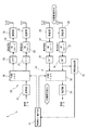
図2は、第1実施形態に係る基地局装置1の内部構成を示す機能ブロック図である。
図2に示すように、本実施形態のスレーブ基地局装置1は、空間分割多重による無線通信の一種であるMIMO(Multiple Input Multiple Output)無線通信を端末装置5との間で実行可能な2系統の送受信系A,Bを備えている。
すなわち、スレーブ基地局装置1の送信機26は、送信データ側から順に、変調器27と、MIMIOエンコーダ28と、2系統の送信系A,Bを備えており、この各送信系A,Bは、それぞれ、IFFT(逆高速フーリエ変換器)29、DAコンバータ30及び送信部31よりなる。
[Internal configuration of slave base station]
FIG. 2 is a functional block diagram showing an internal configuration of the
As shown in FIG. 2, the slave
That is, the
送信機26に入力された送信データは、変調器27においてOFDM方式にてデジタル変調され、MIMOエンコーダ28において所定の行列式で各送信系A,Bにそれぞれ分配して入力される。
各送信系A,Bでは、分配された変調データが、それぞれIFFT29において逆フーリエ変換されてから、DAコンバータ30においてアナログデータに変換され、送信部31を通じて増幅されて外部に送信される。
The transmission data input to the
In each of the transmission systems A and B, the distributed modulation data is subjected to inverse Fourier transform in the
他方、受信機33のアンテナで受信された受信信号は、各受信系A,Bの受信部38において増幅され、ADコンバータ37においてデジタルデータに変換されてから、FTT36においてフーリエ変換され、MIMOデコーダ35に入力される。
MIMOデコーダ35は、各受信系A,Bで得られたフーリエ変換後の受信信号を、MIMOエンコーダ28の行列式と逆の行列式を用いてデコード処理を行ってデジタルデータを再生する。そして、このデジタルデータをOFDM方式の復調器34にて復調することにより、受信データが抽出される。
On the other hand, the received signal received by the antenna of the
The
各受信系A,Bの受信部38は、それぞれ、可変利得アンプ、ミキサ、局部発振器(PLL回路)及び直交復調器等を内部に含んでおり、所定周波数の受信信号を増幅し、その受信信号を直交復調する機能を有する。
受信系B側の受信部38内の局部発振器(PLL回路)は、分周器の分周比を可変に設定可能である。この分周器に対する分周比を後述する同期モード実行部16からの外部制御信号で変更することにより、受信系B側の受信部38の受信周波数を可変に設定できるようになっている。
The
The local oscillator (PLL circuit) in the
また、受信系B側には、FFT36の出力信号からマスタ基地局装置2,3に対する同期信号を抽出する同期検出部15が設けられている。この同期検出部15は、FFT36が出力するシンボル群から、マスタ基地局装置2,3との同期検出ポイントとして、例えば下りサブフレームDLの先頭部分にあるプリアンブルを検出する。
前記MIMOエンコーダ28とMIMOデコーダ35には、後述する同期モード実行部16がそれぞれ接続されている。
On the reception system B side, a
The
〔同期モード実行部の機能〕
図2に示すように、本実施形態のスレーブ基地局装置1は、自装置1の通信モードを通常モード又は同期モードのいずれか一方に切り替える通信制御部である、同期モード実行部16を備えている。
この同期モード実行部16は、起動時に行う同期モードである前記初期同期処理と、その後に所定の実行周期で行う同期モードである前記中間同期処理の双方を実行可能であり、現在の通信モードが「通常モード」か「同期モード」のいずれであるかを示すモード種別を管理している。
[Function of synchronous mode execution unit]
As shown in FIG. 2, the slave
The synchronization
また、同期モード実行部16は、中間同期処理を行う実行周期(例えば、5分)を予め記憶装置に記憶しており、中間同期処理を行わない場合には、端末装置5との間の通常の無線通信(通常モード)をそのまま継続する。
更に、同期モード実行部16は、中間同期処理を行う場合には、MIMOエンコーダ28及びMIMOデコーダ35にそれぞれ休止信号を送って端末装置5とのMIMO通信を停止させ、いずれかのマスタ基地局装置2,3と同期をとるため、当該基地局装置2,3からの送信信号(周波数がf2又はf3)を受信する同期モードを実行する。
In addition, the synchronization
Furthermore, when performing the intermediate synchronization process, the synchronization
また、同期モード実行部16は、自身の使用周波数f1と、同期対象となりうるマスタ基地局装置2,3の使用周波数f2,f3にそれぞれ対応する、局部発振器の分周器に対する外部制御信号(分周比)を予め設定値として記憶領域に記憶している。
そして、モード種別が通常モードである場合、同期モード実行部16は、局部発振器の分周器に対する外部制御信号を自身の使用周波数f1用の値に設定し、受信系Bの受信周波数を自身の使用周波数f1に設定する。
The synchronization
When the mode type is the normal mode, the synchronous
他方、モード種別が同期モードである場合、同期モード実行部16は、受信系B側の局部発振器の分周器に対する外部制御信号を、いずれかのマスタ基地局装置2,3の使用周波数f1,f2用の値に切り替える。
これにより、モード種別が同期モードである場合には、自装置1の使用周波数f1とは異なる使用周波数f2,f3であるマスタ基地局装置2,3からの送信信号を、自装置1の受信機33(受信系B)で受信できるようになっている。
On the other hand, when the mode type is the synchronous mode, the synchronous
As a result, when the mode type is the synchronous mode, the transmission signals from the master
そして、同期モード実行部16は、上記同期モードで受信系B側の同期検出部15が検出した周波数f2,f3の受信信号(マスタ基地局装置2,3からの送信信号)の、下りサブフレームDLの先頭部分のプリアンブルに基づいて同期タイミングを検出する。もっとも、この同期タイミングの検出は、ミッドアンブルやパイロット信号等でも行うことができる。
一方、同期モード実行部16は、自装置1が行う通信モードのモード種別を管理しているが、そのモード種別を常にMIMOエンコーダ28とMIMOデコーダ35に通知している。
The synchronization
On the other hand, the synchronization
モード種別が通常モードである場合には、同期モード実行部16は、2系統の送受信系A,Bを用いた所定のMIMO無線通信が実行されるように、MIMOエンコーダ28とMIMOデコーダ35をそれぞれ制御する。
これに対して、モード種別が同期モードである場合には、同期モード実行部16は、同期モードの実行期間中は、一方の送受信系Aでの無線通信を休止させ、マスタ基地局装置2,3からの送信信号(周波数はf2又はf3)を他方の送受信系Bの受信部38に受信させるように、MIMOエンコーダ28とMIMOデコーダ35をそれぞれ制御する。
When the mode type is the normal mode, the synchronous
On the other hand, when the mode type is the synchronous mode, the synchronous
また、本実施形態の同期モード実行部16は、上記同期モードを実行するに当たって、送受信系Bの受信部38が受信周波数の切り替えを完了するのに十分なガードタイムを、同期モードの実行期間の前後に設定するとともに、このガードタイムの設定期間と重複するように、送受信系Aに端末装置5との無線通信を実行させる時間設定機能を有する。
なお、この同期モード実行部16が行う上記時間設定機能については、図5に示すタイムチャートの説明の時に再論する。
In addition, the synchronization
The time setting function performed by the synchronous
〔同期モード実行部の処理内容〕
図3は、同期モード実行部16が行う、通信モードから同期モードへの切り替え動作のフローチャートを示している。
図3に示すように、まず、同期モード実行部16は、同期モードへの移行タイミングであるか否かの判定を行う(ステップS1)。この移行タイミングは、前記した通り、同期モードの実行周期(所定時間ごと又は所定フレーム数ごと)として設定されている。この実行周期を時間設定する場合、例えば5分程度に設定できるが、これを可変に設定することもできる。
[Processing content of synchronous mode execution unit]
FIG. 3 shows a flowchart of the switching operation from the communication mode to the synchronous mode performed by the synchronous
As shown in FIG. 3, first, the synchronization
図3において、通常モードから同期モードへの移行タイミングになったと判定された場合には(ステップS2でYES)、同期モード実行部16は、自装置4の通信モードを通常モードから同期モードに移行する(ステップS3)。
同期モード実行部16は、その同期モードが終了すると、通信モードを再び通常モードに戻す(ステップS4)。
In FIG. 3, when it is determined that the transition timing from the normal mode to the synchronous mode is reached (YES in step S <b> 2), the synchronous
When the synchronization mode ends, the synchronization
このように、同期モード実行部16は、端末装置5との間で通常の無線通信を行う通常モードを行いつつ、定期的又は必要に応じて随時同期モードを実行するので、初期同期処理の以後にマスタ基地局装置2,3との同期ずれが発生しても、これを解消することができる。
なお、本実施形態では、同期モード実行部16が1回の同期モードを行うために要する時間が、1つの基本フレームの周期と同じ5msに設定されている。
As described above, the synchronization
In the present embodiment, the time required for the synchronization
図4は、中間同期処理の処理内容を示すフローチャートである。
図4に示すように、同期モード実行部16は、同期モードを中間同期処理で実行する場合、まず、その中間同期処理(ステップS11〜S15)を開始する前に、自セル内のすべての端末装置5に対して、端末装置5をスリープモード又はアイドルモード(省電力モード)にするための通知をブロードキャストにて送信する(ステップS10)。
FIG. 4 is a flowchart showing the processing contents of the intermediate synchronization processing.
As shown in FIG. 4, when the synchronization mode is executed in the intermediate synchronization process, the synchronization
端末装置5は、スレーブ基地局装置1からのスリープモードやアイドルモードの通知を受けると、自身の動作モードをその通知に従ったモードに移行する。このスリープモードやアイドルモードは、端末装置5が通信を実行しない場合の管理モードであるため、消費電力が抑えられる。
端末装置5は、少なくとも基地局装置1が同期モードになっていてエア同期を行っている間は、スリープモードやアイドルモードを継続するように時間設定されている。
When receiving the notification of the sleep mode or the idle mode from the slave
The
このように、スレーブ基地局装置1が同期モードの期間中は端末装置5がスリープモード等になっているので、スレーブ基地局装置1からの送信信号の受信不能期間が継続しても、端末装置5が通信異常と判断することはない。
一方、スレーブ基地局装置1は、端末装置5へのスリープモード等の通知後に、中間同期処理による同期モードに移行する。この中間同期処理を行う場合、同期モード実行部16は、自装置1の送信機26に休止信号を送り、自セル内への下りサブフレームDLの送信を休止する。これにより、本来、下りサブフレームDLになる時間帯においても、他のマスタ基地局装置2,3の送信信号を受信可能な状態となる。
As described above, since the
On the other hand, after notifying the
図4に示すように、中間同期処理においては、同期モード実行部16は、まず、モード種別を同期モードに切り替える(ステップS11)。
このさい、同期モード実行部16は、送受信系A,Bによる端末装置5とのMIMO通信を中止させ、受信系Bの局部発振器の分周器への外部制御信号を切り替える。これにより、自身の受信機33の受信体制がマスタ基地局装置2,3用の受信周波数f2,f3に切り替えられ(図3参照)、マスタ基地局装置2,3からの送信信号が受信される(ステップS12)。
As shown in FIG. 4, in the intermediate synchronization process, the synchronization
At this time, the synchronization
その後、同期モード実行部16は、マスタ基地局装置2,3が送信した下りサブフレームDLの先頭部分にあるプリアンブルを同期検出ポイントとして採用し(ステップS13)、その同期検出ポイントに合わせて同期ずれの修正を行う(ステップS14)。
この同期ずれの修正は、検出されたプリアンブルに基づく同期検出ポイントを、自装置1の下りサブフレームDLの送信タイミングと一致するように設定することで行われる。
すなわち、同期モード実行部16は、検出された同期検出ポイントに基づいて自装置1の送信タイミングの時間的誤差を修正することで、自装置1の送信タイミングを同期対象となったマスタ基地局装置2,3の送信タイミングに一致させる。
After that, the synchronization
This synchronization shift is corrected by setting the synchronization detection point based on the detected preamble so as to coincide with the transmission timing of the downlink subframe DL of the
In other words, the synchronization
なお、自装置1の送信タイミングをマスタ基地局装置2,3の送信タイミングと一致させれば、自然に受信タイミングも一致するので、マスタ基地局装置2,3との間でフレーム同期がとれた状態となる。
このように、本実施形態では、端末装置5との間で通常の無線通信を行う通常モードを休止して、他のマスタ基地局装置2,3からの送信信号を傍受して同期をとるため、同期専用の制御用チャネルがなくても他の基地局装置2,3とのエア同期を実施することができる。
In addition, if the transmission timing of the
As described above, in this embodiment, the normal mode in which normal wireless communication is performed with the
以上の中間同期処理による同期ずれの修正が終了すると、同期モード実行部16は、端末装置5へスリープモードの解除通知を行ったうえで(ステップS15)、同期モードを終了させる(ステップS16)。
このさい、通信モードが同期モードから通常モードに切り替えられ、局部発振器への外部制御信号が自身の使用周波数f1用の値に戻る。これにより、受信機33の受信系B側の受信体制が、端末装置5からの送信信号の受信に適した通常の状態に調整される。
When the correction of the synchronization deviation by the above intermediate synchronization processing is completed, the synchronization
At this time, the communication mode is switched from the synchronous mode to the normal mode, and the external control signal to the local oscillator returns to the value for its own use frequency f1. As a result, the reception system on the reception system B side of the
なお、スリープモード等にある端末装置5は、設定されたスリープ時間(又はアイドル時間)が経過すると、自動的にスレーブ基地局装置1との通信を行う通常の動作モードに戻る。
従って、スレーブ基地局装置1と端末装置5がともに、時分割復信による無線通信を行う通常モードに戻り、両者間でその通常モードよる無線通信が再開される。
Note that the
Therefore, both the slave
〔中間同期処理のタイムチャート(2系統の場合)〕
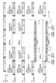
図5は、2系統の送受信系A,Bを有する本実施形態の基地局装置1において、同期モード実行部16が中間同期処理を行った場合のタイムチャートを示している。
図5において、符号Tは基本フレームに含まれる送信フレーム(下りサブフレーム)を示し、符号Rは受信フレーム(上りサブフレーム)を示している。また、基本フレームに含まれる黒塗りの部分は、送信フレームの先頭部分のプリアンブルを示し、横縞のハッチング部分は、送信から受信へのギャップ時間(送信も受信も行われない空白の区間)を示し、斜線のハッチング部分は、受信から送信へのギャップ時間を示している。
[Time chart for intermediate synchronization processing (in the case of 2 systems)]
FIG. 5 shows a time chart when the synchronization
In FIG. 5, a symbol T indicates a transmission frame (downlink subframe) included in a basic frame, and a symbol R indicates a reception frame (uplink subframe). Also, the black part included in the basic frame indicates the preamble at the beginning of the transmission frame, and the hatched part with horizontal stripes indicates the gap time from transmission to reception (blank interval in which neither transmission nor reception is performed). The hatched portion of hatching indicates the gap time from reception to transmission.
図5では、スレーブ基地局装置1(BSs:使用周波数f1)の同期対象がマスタ基地局装置2(BSm2:使用周波数f2)である場合を想定しており、当該図5の上段のタイムチャートは、そのマスタ基地局装置2のフレームの時間的変化を示している。
また、図5の中段のタイムチャートは、スレーブ基地局装置1の送受信系Aのフレームの時間的変化を示し、図5の下段のタイムチャートは、スレーブ基地局装置1の送受信系Bのフレームの時間的変化を示している。
In FIG. 5, it is assumed that the synchronization target of the slave base station apparatus 1 (BSs: use frequency f1) is the master base station apparatus 2 (BSm2: use frequency f2), and the upper time chart of FIG. FIG. 5 shows temporal changes in the frame of the master
Further, the middle time chart of FIG. 5 shows temporal changes in the frames of the transmission / reception system A of the slave
ところで、スレーブ基地局装置1が自身の使用周波数f1とは異なる使用周波数f2のマスタ基地局装置2に対する同期モードを実行する場合、そのマスタ基地局装置2からの送信信号を受信する受信系Bに対する周波数切り替えを行う必要がある。
そして、一般に、局部発振器として常用されるPLL発振器の場合、これをOFDM方式の受信機に使用すると、低い位相雑音やスプリアス特性が必要となるため、ループフィルタの帯域を狭くする必要があるとされている。しかし、ループフィルタの帯域を狭くすると、PLL回路の周波数切替えに要する時間(周波数の設定をしてから周波数が所望値に安定するまでの時間)が長くなり、数ミリ秒程度に及ぶことが分かっている。
By the way, when the slave
In general, in the case of a PLL oscillator that is commonly used as a local oscillator, if this is used for an OFDM receiver, low phase noise and spurious characteristics are required, and therefore the band of the loop filter needs to be narrowed. ing. However, when the loop filter band is narrowed, the time required for switching the frequency of the PLL circuit (the time from setting the frequency until the frequency stabilizes to the desired value) becomes longer, and it is found that it takes several milliseconds. ing.
そこで、図5の下段のタイムチャートで示すように、本実施形態では、同期モード実行部16が、受信系Bの受信部38が受信周波数の切り替えを完了するのに十分なガードタイム(ガード時間)を、同期モードの実行期間の前後に設けるようになっている。
すなわち、同期モード実行部16は、自身の使用周波数f1と異なる周波数f2の同期信号による同期モードを行う場合には、その同期モードの実行期間の前後に、局部発振器(PLL回路)での周波数切り替え時間よりも長いガードタイム(図例では5ms)を設ける。
Therefore, as shown in the lower time chart of FIG. 5, in the present embodiment, the synchronization
That is, when the synchronization
そして、同期モード実行部16は、同期モードを実行する送受信系Bに関しては、上記ガードタイムの設定期間中においても、端末装置5との通常モードでの無線通信を休止させる。
このように、本実施形態のスレーブ基地局装置1によれば、同期モード実行部16が、自身と異なる使用周波数f2のマスタ基地局装置2と同期をとるに当たって、周波数切り替えのためのガードタイムを前後に設定して同期モードを実行するとともに、その同期モードとガードタイムの期間中は通常モードを休止するので、受信部38の受信周波数が不安定な状態で同期モードが実行されることがなく、エア同期を確実に行うことができる。
And the synchronous
Thus, according to the slave
しかし、上記のように、周波数切り替えのためのガードタイムを同期モードの前後に設定すると、送受信系Bに関する通常モードの休止期間が長くなるので(図5の例では、ほぼ基本フレーム3つ分)、送受信系Aについても同じように通信を停止してしまうと、端末装置5と通信不能になり得るという問題がある。
すなわち、端末装置5は、下りサブフレームDLを常時受信して制御情報を取得しているので、ある基地局装置1からの受信不能状態が継続すると、新たな基地局装置を探索する動作を開始してしまう。また、通信効率の点からも、基地局装置1からの送信フレームの停止数は少ない方が望ましい。
However, as described above, if the guard time for frequency switching is set before and after the synchronous mode, the pause period of the normal mode related to the transmission / reception system B becomes longer (in the example of FIG. 5, approximately three basic frames). Similarly, if communication is stopped for the transmission / reception system A, there is a problem that communication with the
That is, since the
従って、同期モードの実行区間を設けることに伴う、下り信号の停止頻度は極力少ない方が好ましい。
そこで、図5の中段のタイムチャートに示すように、本実施形態の同期モード実行部16では、自装置1がMIMO通信のために2系統の送受信系A,Bを備えていることを利用して、送受信系Bが周波数切り替えを行っているガードタイムの期間と重複する時間帯において、他方の送受信系Aに端末装置5との無線通信を実行させる通信制御を行うようになっている。
Accordingly, it is preferable that the stop frequency of the down signal accompanying the execution period of the synchronous mode is as low as possible.
Therefore, as shown in the middle time chart of FIG. 5, the synchronization
すなわち、同期モード実行部16は、一方の送受信系Bにおける同期モードの実行期間中については、他方の送受信系Aによる無線通信も停止させるが、一方の送受信系Bにおけるガードタイムの設定期間中については、そのガードタイムの設定期間と重畳するように、自身の使用周波数f1による1系統のみの無線通信を他方の送受信系Aに実行させるようになっている。
That is, the synchronization
このように、本実施形態のスレーブ基地局装置1によれば、同期モード実行部16が、ガードタイムの設定期間と重複する時間帯に、送受信系Aに端末装置5との無線通信(この場合は、MIMO通信ではなく1系統の無線通信)を実行させるので、受信部38の動作周波数を切り替えるためにガードタイムを設定しても、そのガードタイムの設定期間中に無線通信を継続することができる。
このため、自装置1とは使用周波数が異なるマスタ基地局装置2,3とエア同期を行うに当たって、自装置1の送信フレームの停止数を極力少なくでき、通信効率の低下を最小限に抑えることができる。
なお、第1実施形態(図2)では、端末装置5とMIMO無線通信を行うことを前提として、送信系と受信系の双方がいずれも2系統A,Bである場合を例示したが、送信系については少なくとも1系統あれば足り、この場合でも、ガードタイムの設定時間中での通信継続が可能である。
As described above, according to the slave
For this reason, when performing air synchronization with the master
In the first embodiment (FIG. 2), the case where both the transmission system and the reception system are two systems A and B is illustrated on the assumption that MIMO wireless communication with the
〔第2実施形態〕
〔スレーブ基地局装置の内部構成〕
図6は、第2実施形態に係る基地局装置1の内部構成を示す機能ブロック図である。
この第2実施形態の基地局装置1が第1実施形態のそれと異なる点は、端末装置5とのMIMO無線通信に対応した送受信系の系統数が4系統(A〜D)である点にあり、その他の構成及び機能は第1実施形態の場合と同様である。従って、以下において、第1実施形態とは異なる構成及び機能について重点的に説明する。
[Second Embodiment]
[Internal configuration of slave base station]
FIG. 6 is a functional block diagram showing an internal configuration of the
The
図6に示すように、本実施形態のスレーブ基地局装置1は、端末装置5とのMIMO無線通信が可能な4系統の送受信系A〜Dを備えている。
本実施形態では、4系統の送受信系A〜Dのうち、2つの送受信系C,Dが同期モードを実行する送受信系であり、残りの2つの送受信系A,Bがガードタイムの設定期間中においても端末装置5との無線通信を継続する送受信系になっている。
As shown in FIG. 6, the slave
In the present embodiment, of the four transmission / reception systems A to D, two transmission / reception systems C and D are transmission / reception systems that execute the synchronous mode, and the remaining two transmission / reception systems A and B are in a guard time setting period. Is a transmission / reception system in which wireless communication with the
同期モードを実行する側の2つの受信系C,DのFFT36の後段には、ダイバーシチ合成部17が接続され、この合成部17に同期検出部15が接続されている。
従って、2つの受信系C,Dの受信部38でダイバーシチ受信された合成信号が同期検出部15に入力され、その合成信号に基づいて検出された同期タイミングが同期モード実行部16に入力されるようになっている。
A
Accordingly, the combined signal that is diversity-received by the receiving
〔中間同期処理のタイムチャート(4系統の場合)〕
図7は、本実施形態のように4系統の送受信系A〜Dがある場合に、同期モード実行部16が行う中間同期処理のタイムチャートである。
図7に示すように、本実施形態では、同期モード実行部16は、2つの送受信系C,Dを用いた同期モードの実行期間の前後に、周波数切り替えのためのガードタイム(図例では5ms)をそれぞれ挿入する。
[Time chart for intermediate synchronization processing (for 4 systems)]
FIG. 7 is a time chart of the intermediate synchronization process performed by the synchronization
As shown in FIG. 7, in this embodiment, the synchronization
この場合、同期モード実行部16は、マスタ基地局装置2(使用周波数f2)からの送信信号を2つの受信系C,Dを用いたダイバーシチ受信を行い、この受信信号から検出した同期タイミングを用いて同期ずれの修正を行う。
このため、マスタ基地局装置2からの送信信号を1つの送受信系で受信する場合に比べて、当該送信信号をより確実に受信でき、エア同期を確実に行うことができる。
In this case, the synchronization
For this reason, compared with the case where the transmission signal from the master
一方、本実施形態においても、同期モード実行部16は、送受信系C,Dにおける同期モードの実行期間中については、残りの送受信系A,Bによる無線通信も停止させるが、送受信系C,Dにおけるガードタイムの設定期間中については、そのガードタイムの設定期間と重畳するように、自身の使用周波数f1による2系統のMIMO無線通信を、残りの送受信系A,Bに実行させるようになっている。
On the other hand, in this embodiment, the synchronization
なお、図6に示す4系統の基地局装置1において、同期モードを実行する送受信系の数X(正の整数)と、これを実行しない送受信系の数Y(正の整数)は、それぞれ2つに限定されるものではなく、XとYの和が総系統数(=4)以下となる範囲で任意に設定することができる。例えば、X=3及びY=1とすれば、3つの受信系を用いたダイバーシチ受信によってマスタ基地局装置2,3からの送信信号を受信できる。
また、N系統の送受信系を有する基地局装置の場合、XとYの数の組み合わせは、X+Y≦Nの不等式を満たす範囲で任意に設定することができる。
なお、第2実施形態(図6)では、端末装置5とMIMO無線通信を行うことを前提として、送信系と受信系の双方がいずれも4系統A,Bである場合を例示したが、送信系については少なくとも1系統あれば足り、この場合でも、ガードタイムの設定時間中での通信継続が可能である。この点は、後述する第3実施形態(図8)の場合も同様である。
In the four-system
In the case of a base station apparatus having N transmission / reception systems, the combination of the numbers of X and Y can be arbitrarily set within a range that satisfies the inequality of X + Y ≦ N.
In the second embodiment (FIG. 6), the case where both the transmission system and the reception system are 4 systems A and B is illustrated on the assumption that MIMO wireless communication with the
〔第3実施形態〕
〔スレーブ基地局装置の内部構成〕
図8は、第3実施形態に係る基地局装置1の内部構成を示す機能ブロック図である。
この第3実施形態の基地局装置1は、MIMO無線通信に対応した送受信系の系統数が4系統(A〜D)である点で第2実施形態の基地局装置1と同様である。しかし、第3実施形態では、自装置1の使用周波数f1と異なる複数の周波数f2,f3の信号を受信系C,Dにおいて個別かつ同時に受信する点で、第2実施形態の場合と異なる。従って、以下において、第2実施形態とは異なる構成及び機能について重点的に説明する。
[Third Embodiment]
[Internal configuration of slave base station]
FIG. 8 is a functional block diagram showing an internal configuration of the
The
本実施形態では、同期モード実行部16が、同期モード用の2つの受信系C,Dの受信部38内の局部発振器(PLL回路)に対し、それぞれ外部制御信号を送信可能となっている。これにより、各受信系C,Dの受信周波数を、同時に異なる値(例えば、マスタ基地局装置2の使用周波数f2とマスタ基地局装置3の使用周波数f3)に設定することができる。
In this embodiment, the synchronization
また、本実施形態のスレーブ基地局装置1では、同期モードを実行する側の2つの受信系C,Dの後段にそれぞれ同期検出部15C,15Dが接続され、各受信系C,Dで受信した信号に対して個別に同期タイミングを検出可能となっている。この各同期検出部15C,15Dの検出信号は、後述する探索部(探索手段)18に送られる。
この探索部(探索手段)18は、各受信系C,Dでそれぞれ受信した、マスタ基地局装置2,3からの周波数が異なる2種類の送信信号に基づいて、同期対象とすべきマスタ基地局装置2,3を探索する。
In the slave
The search unit (search means) 18 is a master base station to be synchronized based on two types of transmission signals received by the receiving systems C and D and having different frequencies from the master
具体的には、探索部18は、例えば、受信部38内にある検波回路等のレベル検出器で検出された受信レベル(RSSI:Received Signal Strength Indicator)に基づいて、受信状態のよい送信信号を特定し、この送信信号に対応するマスタ基地局装置2,3を同期対象として選択する。
なお、探索部18は、通常の受信機において一般に検出されるCINR(Carrier to Interference and Noise Ratio)の値に基づいて、受信系C,Dにおける受信状態の良否を判定することもできる。
Specifically, for example, the
Note that the
〔中間同期処理のタイムチャート(4系統の場合)〕
図9は、本実施形態のように4系統の送受信系A〜Dがある場合に、同期モード実行部16が行う別の中間同期処理のタイムチャートである。
図9に示すように、この場合も、同期モード実行部16は、2つの送受信系C,Dを用いた同期モードの実行期間の前後に、周波数切り替えのためのガードタイム(図例では5ms)をそれぞれ挿入する。
[Time chart for intermediate synchronization processing (for 4 systems)]
FIG. 9 is a time chart of another intermediate synchronization process performed by the synchronization
As shown in FIG. 9, also in this case, the synchronization
そして、本実施形態においても、同期モード実行部16は、2つの送受信系C,Dにおける同期モードの実行期間中については、残りの2つの送受信系A,Bによる無線通信も停止させるが、2つの送受信系C,Dにおけるガードタイムの設定期間中については、そのガードタイムの設定期間と重畳するように、自身の使用周波数f1による2系統のMIMO無線通信を残りの2つの送受信系A,Bに実行させるようになっている。
Also in this embodiment, the synchronization
一方、図9の下部2段のタイムチャートに示すように、本実施形態では、一方の受信系Cによる周波数f2の送信信号(マスタ基地局装置2からの送信信号)の受信と、他方の受信系Dによる周波数f3の送信信号(マスタ基地局装置3からの送信信号)の受信とを、同じ同期モードの実行期間に同時に行う。
そして、2つの受信系C,Dがそれぞれ受信した周波数f2,f3の信号の受信レベル等に基づいて、同期対象とすべきマスタ基地局装置2,3を探索部18が特定し、特定された同期対象に対応する同期タイミングが同期モード実行部16に通知される。
その後、同期モード実行部16は、その通知された同期タイミングに基づいて自身の送信タイミングを修正し、同期ずれを解消する。
On the other hand, as shown in the lower two-stage time chart of FIG. 9, in this embodiment, the reception signal of the frequency f2 (transmission signal from the master base station apparatus 2) by one reception system C and the other reception are received. Reception of a transmission signal of frequency f3 (transmission signal from master base station apparatus 3) by system D is simultaneously performed during the execution period of the same synchronization mode.
Then, based on the reception levels of the signals of the frequencies f2 and f3 received by the two receiving systems C and D, the
Thereafter, the synchronization
このように、本実施形態の基地局装置1によれば、使用周波数f2,f3が異なる複数種類のマスタ基地局装置2,3からの送信信号を、送受信系A〜Dのうちの一部の受信系C,Dが個別にかつ同時に受信するので、その受信を時分割で行う場合に比べて、探索部18が同期対象の探索を行うための同期モードの実行期間を全体的に短縮することができ、エア同期をより短時間で実行できるという利点がある。
As described above, according to the
なお、図8に示す4系統の基地局装置1においても、同期モードを実行する送受信系の数X(正の整数)と、これを実行しない送受信系の数Y(正の整数)は、それぞれ2つに限定されるものではなく、XとYの和が総系統数(=4)以下となる範囲で任意に設定することができる。例えば、X=3及びY=1とすれば、3種類の周波数の送信信号に対する同期モードを同時に実施することができる。
また、N系統の送受信系を有する基地局装置の場合、XとYの数の組み合わせは、X+Y≦Nの不等式を満たす範囲で任意に設定できる。
In the four-system
In the case of a base station apparatus having N transmission / reception systems, the combination of the numbers of X and Y can be arbitrarily set within a range that satisfies the inequality X + Y ≦ N.
上記実施形態はすべて例示であって制限的なものではない。すなわち、本発明の技術的範囲は、上記実施形態ではなく特許請求の範囲によって示され、特許請求の範囲に記載した構成と均等の範囲内でのすべての変更が含まれる。
例えば、上記実施形態では、基地局装置1〜3と端末装置5とがTDD(Time Division Duplex:時分割複信)によって通信を行う無線通信システムを例示したが、本発明は、基地局装置1〜3と端末装置5とがFDD(Frequency Division Duplex:周波数分割複信)によって通信する無線通信システムにも適用することができる。なお、このFDDの場合には、基地局装置1〜3は、端末装置5との通信を休止しなくても、同期モードを実行し得る。
The above embodiments are all illustrative and not restrictive. That is, the technical scope of the present invention is shown not by the above embodiment but by the scope of claims for patent, and includes all modifications within the scope equivalent to the configurations described in the scope of claims for patent.
For example, in the said embodiment, although the base station apparatuses 1-3 and the
1:スレーブ基地局装置(BSs) 2:マスタ基地局装置(BSm2)
3:マスタ基地局装置(BSm3) 5:端末装置(MS)
15:同期検出部 16:同期モード実行部(同期モード実行手段、時間設定手段)
17:ダイバーシチ合成部 18:探索部(探索手段)
26:送信機 27:変調器 28:MIMOエンコーダ
29:IFFT(逆高速フーリエ変換器) 30:DAコンバータ 31:送信部
33:送信機 34:復調器 35:MIMOデコーダ
36:FFT(高速フーリエ変換器) 37:ADコンバータ 38:受信部
A〜D:送受信系
1: Slave base station apparatus (BSs) 2: Master base station apparatus (BSm2)
3: Master base station device (BSm3) 5: Terminal device (MS)
15: Synchronization detection unit 16: Synchronization mode execution unit (synchronization mode execution means, time setting means)
17: Diversity combining unit 18: Search unit (search means)
26: Transmitter 27: Modulator 28: MIMO encoder 29: IFFT (Inverse Fast Fourier Transformer) 30: DA converter 31: Transmitter 33: Transmitter 34: Demodulator 35: MIMO decoder 36: FFT (Fast Fourier Transformer) 37: AD converter 38: Receiver A to D: Transmission / reception system
Claims (4)
少なくとも1つの送信系と複数系統の受信系とを含む送受信系と、
使用周波数が自身と異なる他の基地局装置と同期をとるために、前記他の基地局装置からの送信信号を複数系統の前記受信系のうちの一部に受信させる同期モードを実行する同期モード実行手段と、
一部の前記受信系が受信周波数の切り替えを完了するのに十分なガードタイムを前記同期モードの実行期間の前後に設定し、このガードタイムの設定期間と重複するように、一部の前記受信系を除いた残りの前記送受信系に前記端末装置との無線通信を実行させる時間設定手段と、
を備えていることを特徴とする基地局装置。 A base station device that performs wireless communication with a terminal device,
A transmission / reception system including at least one transmission system and a plurality of reception systems;
A synchronization mode for executing a synchronization mode in which a part of the plurality of reception systems receives a transmission signal from the other base station apparatus in order to synchronize with another base station apparatus that uses a different frequency. Execution means;
A part of the reception system is set so that a guard time sufficient to complete the switching of the reception frequency is set before and after the execution period of the synchronous mode, and is overlapped with the setting period of the guard time. Time setting means for causing the remaining transmission / reception system excluding the system to perform wireless communication with the terminal device;
A base station apparatus comprising:
前記同期モード実行手段は、複数の前記他の基地局装置がそれぞれ送信した周波数が異なる複数種類の前記送信信号を前記受信系の受信部に個別にかつ同時に受信させる請求項1に記載の基地局装置。 The other base station device is composed of a plurality of base station devices each having a different use frequency,
2. The base station according to claim 1, wherein the synchronization mode execution unit causes the reception unit of the reception system to individually and simultaneously receive a plurality of types of the transmission signals having different frequencies transmitted from the plurality of other base station apparatuses. apparatus.
Priority Applications (1)
| Application Number | Priority Date | Filing Date | Title |
|---|---|---|---|
| JP2008289883A JP5155105B2 (en) | 2008-11-12 | 2008-11-12 | Base station equipment |
Applications Claiming Priority (1)
| Application Number | Priority Date | Filing Date | Title |
|---|---|---|---|
| JP2008289883A JP5155105B2 (en) | 2008-11-12 | 2008-11-12 | Base station equipment |
Publications (2)
| Publication Number | Publication Date |
|---|---|
| JP2010118841A JP2010118841A (en) | 2010-05-27 |
| JP5155105B2 true JP5155105B2 (en) | 2013-02-27 |
Family
ID=42306216
Family Applications (1)
| Application Number | Title | Priority Date | Filing Date |
|---|---|---|---|
| JP2008289883A Expired - Fee Related JP5155105B2 (en) | 2008-11-12 | 2008-11-12 | Base station equipment |
Country Status (1)
| Country | Link |
|---|---|
| JP (1) | JP5155105B2 (en) |
Families Citing this family (5)
| Publication number | Priority date | Publication date | Assignee | Title |
|---|---|---|---|---|
| JP2012175345A (en) * | 2011-02-21 | 2012-09-10 | Jvc Kenwood Corp | Wireless device and transmission method |
| WO2014070056A1 (en) | 2012-10-31 | 2014-05-08 | Telefonaktiebolaget L M Ericsson (Publ) | Distribution of synchronization packets over wifi transport links |
| JP6151559B2 (en) * | 2013-05-17 | 2017-06-21 | 京セラ株式会社 | Base station and synchronization method thereof |
| JP2018019233A (en) * | 2016-07-27 | 2018-02-01 | ソフトバンク株式会社 | Base station, communication system, and synchronization signal transmission device |
| JP2018019234A (en) * | 2016-07-27 | 2018-02-01 | ソフトバンク株式会社 | Base station, communication system, and synchronization signal transmission device |
Family Cites Families (5)
| Publication number | Priority date | Publication date | Assignee | Title |
|---|---|---|---|---|
| DE19916064C2 (en) * | 1999-04-09 | 2003-02-20 | Siemens Ag | Synchronization procedure for base stations |
| JP4340605B2 (en) * | 2004-08-27 | 2009-10-07 | 日本電信電話株式会社 | Wireless packet communication method, wireless packet communication apparatus and system |
| JP2007208333A (en) * | 2006-01-30 | 2007-08-16 | Kyocera Corp | Base station apparatus |
| JP2008113359A (en) * | 2006-10-31 | 2008-05-15 | Sanyo Electric Co Ltd | Base station and control method |
| JP2009188497A (en) * | 2008-02-04 | 2009-08-20 | Mitsubishi Electric Corp | Radio communication system |
-
2008
- 2008-11-12 JP JP2008289883A patent/JP5155105B2/en not_active Expired - Fee Related
Also Published As
| Publication number | Publication date |
|---|---|
| JP2010118841A (en) | 2010-05-27 |
Similar Documents
| Publication | Publication Date | Title |
|---|---|---|
| US8730938B2 (en) | Minimizing the impact of self synchronization on wireless communication devices | |
| US8929191B2 (en) | Base station device for wireless communication of OFDM signal including a synchronization control unit | |
| JP5145429B2 (en) | Transmission of system configuration information in mobile WIMAX system | |
| US9603025B2 (en) | Method and apparatus for synchronization mechanisms on un-licensed band | |
| JP2019519978A (en) | Pause mode measurement optimization | |
| US9084193B2 (en) | Base station device | |
| JP5451853B2 (en) | Base station apparatus and synchronization signal acquisition method | |
| WO2016054855A1 (en) | Synchronization for low coverage machine type communication devices | |
| JP5155105B2 (en) | Base station equipment | |
| GB2509088A (en) | A reference sequence for synchronisation and channel estimation in local area communication scenarios | |
| JP2010118726A (en) | Base station device | |
| US8374139B2 (en) | Low latency synchronization scheme for wireless OFDMA systems | |
| WO2011043372A1 (en) | Base station device, signal processing device for base station device, phy processing device, and mac processing device | |
| KR101712914B1 (en) | Method and apparatus of relaying operation using uplink resource | |
| US20220256486A1 (en) | Scheduled device-specific synchronization signals | |
| JP2010041712A (en) | Base station device | |
| JP5605107B2 (en) | Base station equipment | |
| JP5391985B2 (en) | Base station apparatus, signal processing apparatus for base station apparatus, PHY processing apparatus, and MAC processing apparatus | |
| WO2019168660A1 (en) | Transmission of synchronization and wake-up signals in different frequency bands | |
| JP4983834B2 (en) | Base station equipment | |
| JP2010093425A (en) | Base station device and radio communication system | |
| JP5434462B2 (en) | Base station equipment | |
| WO2023055883A1 (en) | Group random access | |
| JP2011082830A (en) | Base station apparatus |
Legal Events
| Date | Code | Title | Description |
|---|---|---|---|
| A621 | Written request for application examination |
Free format text: JAPANESE INTERMEDIATE CODE: A621 Effective date: 20110527 |
|
| A977 | Report on retrieval |
Free format text: JAPANESE INTERMEDIATE CODE: A971007 Effective date: 20121001 |
|
| TRDD | Decision of grant or rejection written | ||
| A01 | Written decision to grant a patent or to grant a registration (utility model) |
Free format text: JAPANESE INTERMEDIATE CODE: A01 Effective date: 20121113 |
|
| A61 | First payment of annual fees (during grant procedure) |
Free format text: JAPANESE INTERMEDIATE CODE: A61 Effective date: 20121206 |
|
| FPAY | Renewal fee payment (event date is renewal date of database) |
Free format text: PAYMENT UNTIL: 20151214 Year of fee payment: 3 |
|
| R150 | Certificate of patent or registration of utility model |
Free format text: JAPANESE INTERMEDIATE CODE: R150 |
|
| LAPS | Cancellation because of no payment of annual fees |