JP5154621B2 - Digital signal transmission method and receiver - Google Patents
Digital signal transmission method and receiver Download PDFInfo
- Publication number
- JP5154621B2 JP5154621B2 JP2010199285A JP2010199285A JP5154621B2 JP 5154621 B2 JP5154621 B2 JP 5154621B2 JP 2010199285 A JP2010199285 A JP 2010199285A JP 2010199285 A JP2010199285 A JP 2010199285A JP 5154621 B2 JP5154621 B2 JP 5154621B2
- Authority
- JP
- Japan
- Prior art keywords
- block
- transmission
- channel value
- digital signal
- reception
- Prior art date
- Legal status (The legal status is an assumption and is not a legal conclusion. Google has not performed a legal analysis and makes no representation as to the accuracy of the status listed.)
- Expired - Fee Related
Links
Images


Landscapes
- Detection And Prevention Of Errors In Transmission (AREA)
Description
本発明は、デジタル信号伝送方法および受信装置に関する。 The present invention relates to a digital signal transmission method and a receiving apparatus.
従来、デジタル信号伝送における伝送効率や伝送品質を高める方法として、ハイブリッド再送制御(Hybrid Auto Repeat reQuest;HARQ)の技術が知られている。HARQは、誤り訂正と再送制御を組み合わせた伝送方式であり、具体的には、送信情報に誤り訂正を施したパケットを送信し、そのパケットが正しく受信されなかった場合に同一の送信情報に基づいて作成した別のパケットを送信して、受信側でそれら複数のパケットから元の送信情報を正しく取り出すというものである。
ここで、HARQの代表的な方式として、IR(Incremental Redundancy)法とチェイス合成(Chase Combining)法があり、以下に図面を使ってこれらを説明する。
2. Description of the Related Art Conventionally, a hybrid retransmission control (HARQ) technique is known as a method for improving transmission efficiency and transmission quality in digital signal transmission. HARQ is a transmission method that combines error correction and retransmission control. Specifically, based on the same transmission information when a packet in which error correction is performed on transmission information is transmitted and the packet is not correctly received. Another packet created in this way is transmitted, and the original transmission information is correctly extracted from the plurality of packets on the receiving side.
Here, as a representative method of HARQ, there are an IR (Incremental Redundancy) method and a Chase Combining method, which will be described below with reference to the drawings.
<IR法>
図9はIR法によるデジタル伝送を行う送信装置30のブロック図、図10は同じく受信装置40のブロック図である。
図9において、送信される情報ビットは符号化器301に入力されて誤り訂正符号化が施され、情報ビットとパリティビットからなる符号語が出力される。出力された符号語のうち、情報ビット全部とパリティビットの前半一部からなるビットは初回送信ブロックとして、残りのパリティビットは次回送信ブロックとして、それぞれバッファ302に蓄えられ、これらの各ブロックは順に変調器303に入力される。変調器303は、入力された各ブロックを変調して対応する変調シンボルを生成し、送信機(図示せず)がこの変調シンボルを送信する。このようにして、ある情報ビットを送信する場合に、初めに初回送信ブロック、次に次回送信ブロックという形で送信が行われる。
<IR method>
FIG. 9 is a block diagram of the
In FIG. 9, information bits to be transmitted are input to an
次に、図10において、まず復調器401は初めに受信された初回受信ブロック(初回送信ブロックに対応する)を復調してブロック合成回路402へ出力する。この時、次回送信ブロックはまだ送信されていないので、ブロック合成回路402は送信されなかったパリティビットはパンクチャ(無効化)されたものとして処理し、入力された初回受信ブロックをそのまま復号化器403に出力する。復号化器403は入力されたブロックを復号して情報ビットを取り出すが、ここでは、図1における元の符号語全体のうち一部のパリティビットを使用していないから、符号化率が符号語全体を使用した場合よりも高いものとして復号化が行われることになる。
Next, in FIG. 10, first, the
この復号化において、初回受信ブロックが正しく復号化できなかった場合には、受信装置側はそれを送信装置側に通知し、これを受けた送信装置30は新たに次回送信ブロックを送信する。
すると、上記と同様にして次回受信ブロック(次回送信ブロックに対応する)が復調されてブロック合成回路402に入力されるが、今回は、初回および次回受信ブロックが直列に合成されてから復号化器403へ送られる。そして、復号化器403は、合成されたブロックの全体に対して復号化を行い、情報ビットを取り出す。ここで、この時の符号化率は、初回受信ブロックのみで復号化した時の符号化率よりも小さくなっている。したがって、復号化の誤り訂正能力が向上することとなり、初回の復号に比べて高い確率で復号が成功することとなる。
In this decoding, when the first received block cannot be correctly decoded, the receiving apparatus side notifies the transmitting apparatus side, and the transmitting
Then, in the same manner as described above, the next reception block (corresponding to the next transmission block) is demodulated and input to the
<チェイス合成法>
図11はチェイス合成法によるデジタル伝送を行う送信装置31のブロック図、図12は同じく受信装置41のブロック図である。
図11において、チェイス合成法では、符号語がメモリ304で複製されて変調器303へ送られる。そして、複製の単位(つまり元の符号語)毎にブロック分割され、それぞれ初回送信ブロック、次回送信ブロックとして順に送信される。すなわち、チェイス合成法では初回も次回も送信される情報は同じである。なお、メモリ304は変調器303の後段に置く構成とすることもでき、同じ動作を実現できる。
<Chase synthesis method>
FIG. 11 is a block diagram of the
In FIG. 11, in the chase combining method, the code word is duplicated in the
次に、図12において、初回受信ブロックに対する処理はIR法と同様にして行われる。初回受信ブロックだけでは正しく復号化できず、次回送信ブロックが送られてきた場合は、ブロック合成回路402は初回および次回受信ブロックを同相で合成して、復号化器403に出力する。ここで、復号化器403への入力はビット当たりの電力が初回時よりも増しているため、初回に比べて高い確率で復号が成功することになる(なお、IR法と異なり、符号化率は初回と次回で変わらない)。
Next, in FIG. 12, the process for the first reception block is performed in the same manner as the IR method. If the first transmission block cannot be correctly decoded and the next transmission block is sent, the
以上のIR法とチェイス合成法は、それぞれ単独で用いるだけでなく、これらを組み合わせて伝送を行うことも可能である。図13は、この組み合わせによる伝送を行う送信装置32のブロック図である。同図において、符号語はメモリ304で複製された後、第1送信ブロックから第4送信ブロックの4つのブロックに分割されて変調器303へ送られる。第1・第3送信ブロックはIR法における初回送信ブロックと同じく情報ビットとパリティビットの一部分から構成され、第2・第4送信ブロックはIR法の次回送信ブロックと同じく残りのパリティビットで構成される。
そして受信側(対応する受信装置のブロック図は省略)では、第1および第2受信ブロックを受信した時の処理は上記IR法と同様の処理を行い、第3、第4受信ブロックを受信した時は、これら新たに受信したブロックを上記チェイス合成法の処理と同様に、既に受信済みのブロックと同相に合成し、復号化を行う。
The above IR method and chase combining method can be used not only independently but also in combination for transmission. FIG. 13 is a block diagram of the
On the receiving side (the block diagram of the corresponding receiving device is omitted), the processing when receiving the first and second receiving blocks is the same as the IR method, and the third and fourth receiving blocks are received. At the same time, these newly received blocks are synthesized in phase with the already received blocks in the same manner as in the above chase synthesis method, and are decoded.
なお、周波数分割した多数の搬送波を用いるマルチキャリア伝送方式に上述した各種のHARQを適用する場合、送信ブロック毎に伝送パラメータを同一にするのが通常であるが、スループットを部分的に向上させる方法として、非特許文献1には、IR法を用いる場合に情報ビットだけからなる第1送信ブロックを送信するときのみWalsh符号拡散多重を行い、パリティビットを送信するときは符号拡散多重をしないことが好ましい方法であると紹介されている。 In addition, when applying the various HARQs described above to a multi-carrier transmission system using a large number of frequency-divided carriers, it is normal to make the transmission parameters the same for each transmission block, but a method for partially improving the throughput In Non-Patent Document 1, when the IR method is used, Walsh code spread multiplexing is performed only when the first transmission block consisting only of information bits is transmitted, and code spread multiplexing is not performed when transmitting parity bits. It is introduced as a preferred method.
上述したIR法を用いたデジタル信号伝送方法では、2回目以降の伝送において多くのパリティビットが伝送されることで周波数ダイバシチ効果が得られるが、その反面、拡散多重信号の逆拡散受信による符号間干渉などの劣化要因が顕著となる。また、チェイス合成法では、2回目以降の伝送でブロック合成により受信S/Nが上がって符号間干渉の影響が相対的に小さくなるというメリットを生かしきれていない。このように、従来のHARQ方式は、伝送パラメータが必ずしも最適化されていないため、スループットの面で問題があり、高品質な伝送を実現できないという課題があった。
本発明は上記の点に鑑みてなされたものであり、その目的は、スループットを向上させて高品質な伝送を可能とするデジタル信号伝送方法および受信装置を提供することにある。
In the digital signal transmission method using the IR method described above, a frequency diversity effect is obtained by transmitting a large number of parity bits in the second and subsequent transmissions. Deterioration factors such as interference become prominent. Further, the chase combining method cannot take full advantage of the fact that the reception S / N is increased by block combining in the second and subsequent transmissions, and the influence of intersymbol interference becomes relatively small. As described above, the conventional HARQ method has a problem in terms of throughput because transmission parameters are not necessarily optimized, and there is a problem that high-quality transmission cannot be realized.
The present invention has been made in view of the above points, and an object of the present invention is to provide a digital signal transmission method and a receiving apparatus that improve throughput and enable high-quality transmission.
本発明は上記の課題を解決するためになされたものであり、本発明は、送信する情報ビットを符号化して得られた符号語を変調し、該変調によって得られた変調シンボルを2以上のブロックに分割して伝送するデジタル信号伝送方法であって、前記分割された全てのブロックを受信する前に復号を開始して、まだ受信していない未受信ブロックに含まれる変調シンボルの受信確率を、復号済みの変調シンボルの受信確率に基づいて予測し、前記未受信ブロックを受信して該ブロックに含まれる変調シンボルを復調するとき、前記予測された受信確率に基づいて通信路値を求めることを特徴とするデジタル信号伝送方法である。 The present invention has been made to solve the above problems, and the present invention modulates a codeword obtained by encoding information bits to be transmitted, and converts the modulation symbols obtained by the modulation into two or more modulation symbols. A digital signal transmission method for transmitting divided into blocks, wherein decoding is started before all the divided blocks are received, and the reception probability of a modulation symbol included in an unreceived block that has not yet been received is determined. Predicting based on the reception probability of a decoded modulation symbol, and obtaining a channel value based on the predicted reception probability when receiving the unreceived block and demodulating the modulation symbol included in the block. A digital signal transmission method characterized by the above.
また、本発明は、上記のデジタル信号伝送方法を用いて送信および/または受信を行う場合において、前記分割された全てのブロックを受信する前に、その時点までに復号された結果から前記情報ビットが正しく復号されたときは、送信側に通知して残りのブロックの送信を中止させることを特徴とするデジタル信号伝送方法である。 Further, in the case of performing transmission and / or reception using the above-described digital signal transmission method, the present invention provides the information bit from the result of decoding up to that point before receiving all the divided blocks. Is a digital signal transmission method characterized in that when the signal is correctly decoded, the transmission side is notified to stop the transmission of the remaining blocks.
また、本発明は、上記のデジタル信号伝送方法を用いて送信および/または受信を行う場合において、前記分割された全てのブロックを受信する前に、その時点までに復号された結果から前記情報ビットが正しく復号されなかったときは、送信側に通知して残りのブロックを送信させることを特徴とするデジタル信号伝送方法である。 Further, in the case of performing transmission and / or reception using the above-described digital signal transmission method, the present invention provides the information bit from the result of decoding up to that point before receiving all the divided blocks. Is a digital signal transmission method characterized in that when the signal is not correctly decoded, the remaining block is transmitted by notifying the transmission side.
また、本発明は、送信する情報ビットを符号化して得られた符号語を変調し、該変調によって得られた変調シンボルを2以上のブロックに分割して伝送するデジタル信号伝送において、まだ受信していない未受信ブロックに含まれる変調シンボルの受信確率を、復号済みの変調シンボルの受信確率に基づいて予測し、前記未受信ブロックを受信して該ブロックに含まれる変調シンボルを復調するとき、前記予測された受信確率に基づいて通信路値を求める復調手段を備えることを特徴とする受信装置である。 Further, the present invention modulates a code word obtained by encoding information bits to be transmitted, and in digital signal transmission in which a modulation symbol obtained by the modulation is divided into two or more blocks and transmitted. Predicting a reception probability of a modulation symbol included in an unreceived block that is not received based on a reception probability of a decoded modulation symbol, and receiving the unreceived block and demodulating the modulation symbol included in the block, A receiving apparatus comprising demodulation means for obtaining a channel value based on a predicted reception probability.
本発明によれば、送信ブロック毎に符号多重数あるいは回転符号の角度を変えて各ブロックを送信し、また、既に復号された受信ビットの確からしさからまだ受信していない受信ビットの確からしさを推定して復調を行うので、伝送スループットを向上させ高品質な伝送を行うことが可能である。 According to the present invention, each block is transmitted by changing the number of code multiplexes or the angle of the rotation code for each transmission block, and the probability of the received bit that has not been received yet is determined from the probability of the received bit that has already been decoded. Since estimation and demodulation are performed, transmission throughput can be improved and high-quality transmission can be performed.
以下、図面を参照しながら本発明の実施形態について詳しく説明する。
≪第1の実施形態≫
図1と図2は、本発明の第1の実施形態によるデジタル信号伝送方法を説明する図であり、図1が送信装置10のブロック図、図2が受信装置20のブロック図である。本実施形態は、IR法によるHARQを基にしたものである。
Hereinafter, embodiments of the present invention will be described in detail with reference to the drawings.
<< First Embodiment >>
1 and 2 are diagrams for explaining a digital signal transmission method according to the first embodiment of the present invention, in which FIG. 1 is a block diagram of a
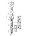
図1において、送信される情報ビットは符号化器101に入力されて誤り訂正符号化が施され、情報ビットとパリティビットからなる符号語が出力される。出力された符号語のうち、情報ビット全部とパリティビットの前半一部からなるビットは初回送信ブロックとして、残りのパリティビットは次回送信ブロックとして、それぞれ順に変調器102に入力される。変調器102は、入力ビットを変調して対応する変調シンボルを生成し、シリアルパラレル(S/P)変換器103へ送る。S/P変換器103に入力された変調シンボルをAとBで表すことにする。変調シンボルA、Bは、拡散多重化器104に入力されて、サブキャリアF1とF2にマッピングされる。このマッピングされたシンボルをX、Yとすると、拡散多重の操作は次式で表される。
In FIG. 1, information bits to be transmitted are input to an

Cは2×2の行列であり、次数2の拡散多重符号を与えるものである。なお、次数が4の場合には、4つの変調シンボルと4つのサブキャリアを関係付ける4×4の行列によって拡散多重符号が定義される。なお、行列Cの具体例として、次数をその長さとするWalsh-Hadamard行列などがある。
上式で与えられるサブキャリア上のシンボルX、Yは、逆高速フーリエ変換(IFFT)器105を介して送信機(図示せず)から送信される。
C is a 2 × 2 matrix that gives a spread multiplex code of
Symbols X and Y on the subcarrier given by the above equation are transmitted from a transmitter (not shown) via an inverse fast Fourier transform (IFFT)
次に、図2において、まず高速フーリエ変換(FFT)器201を介して復調器202に入力された初回受信ブロック(初回送信ブロックに対応する)は、復調後、ブロック合成回路203へ出力される。この時、次回送信ブロックはまだ送信されていないので、ブロック合成回路203は送信されなかったパリティビットはパンクチャ(無効化)されたものとして処理し、入力された初回受信ブロックをそのまま復号化器204に出力する。復号化器204は入力されたブロックを復号して情報ビットを取り出す。
Next, in FIG. 2, the first reception block (corresponding to the first transmission block) first input to the
この復号化において、初回受信ブロックが正しく復号化できなかった場合には、受信装置側はそれを送信装置側に通知し、これを受けた送信装置10は新たに次回送信ブロックを送信する。
すると、上記と同様にして次回受信ブロック(次回送信ブロックに対応する)が復調されてブロック合成回路203に入力されるが、今回は、初回および次回受信ブロックが直列に合成されてから復号化器204へ送られる。そして、復号化器204は、合成されたブロックの全体に対して復号化を行い、情報ビットを取り出す。
In this decoding, when the first received block cannot be correctly decoded, the receiving apparatus side notifies the transmitting apparatus side, and the transmitting
Then, in the same manner as described above, the next reception block (corresponding to the next transmission block) is demodulated and input to the
ここで、本実施形態では、前に送信するブロック(初回送信ブロック)の拡散多重の次数を、後に送信するブロック(次回送信ブロック)の拡散多重の次数より大きくして伝送を行う。このような伝送パラメータの調整を行うと、
(1) 符号化率が高い初回の送信においては、より大きな周波数ダイバシチ効果が得られる高次数の拡散多重符号を用いることで伝送特性を向上させることができ、
(2) 2回目以降の送信においては、多くのパリティビットが伝送されてブロック合成が行われるので、符号化率が小さくなってより高い周波数ダイバシチ効果が得られるようになる。この条件下では、符号間干渉などによる劣化要因となる拡散多重の度合いは、むしろ抑えた方が伝送特性を向上させることができる。ただし、拡散多重信号を逆拡散せずに復調することで符号間干渉を抑える効果が得られるので、2回目以降の送信においても低次の拡散多重符号を用いて送信することが望ましい。
伝送パラメータを上記のように最適化することで、本実施形態によれば従来技術より伝送スループットを向上させ、高品質な伝送を行うことが可能である。
Here, in the present embodiment, transmission is performed with the spread multiplexing order of the block (first transmission block) transmitted before being larger than the spread multiplexing order of the block (next transmission block) transmitted later. When such transmission parameter adjustment is performed,
(1) In the first transmission with a high coding rate, the transmission characteristics can be improved by using a high-order spread multiplexing code that can obtain a larger frequency diversity effect,
(2) In the second and subsequent transmissions, since many parity bits are transmitted and block synthesis is performed, the coding rate is reduced and a higher frequency diversity effect can be obtained. Under these conditions, it is possible to improve the transmission characteristics by suppressing rather the degree of spreading multiplexing that causes deterioration due to intersymbol interference. However, since the effect of suppressing intersymbol interference can be obtained by demodulating the spread multiplexed signal without despreading, it is desirable to transmit using the low-order spread multiplexed code in the second and subsequent transmissions.
By optimizing the transmission parameters as described above, according to the present embodiment, it is possible to improve the transmission throughput over the prior art and perform high-quality transmission.
≪第2の実施形態≫
本実施形態では、拡散多重符号として回転符号を適用する。この場合、前に送信するブロックと後に送信するブロックとで拡散多重の次数を変化させる代わりに、回転符号の回転角を、送信する順番の遅いブロックほど小さくして伝送を行う。このような伝送パラメータを用いることで、第1の実施形態の場合と同様に伝送スループットを向上させることができる。なお、回転行列は次数が2の場合次式で与えられる。ただし、符号多重化しない場合と等価な信号になる角度を0°とし、Walsh-Hadamard符号と等価な信号になる角度を45°としたとき、角度θは0から45°の範囲であるものとする。
<< Second Embodiment >>
In this embodiment, a rotation code is applied as the spread multiplex code. In this case, instead of changing the order of spreading multiplexing between the block to be transmitted before and the block to be transmitted later, transmission is performed with the rotation angle of the rotation code being made smaller in the block with the later transmission order. By using such transmission parameters, it is possible to improve the transmission throughput as in the case of the first embodiment. The rotation matrix is given by the following equation when the order is 2. However, when the angle that becomes a signal equivalent to the case where the code is not multiplexed is 0 ° and the angle that becomes a signal equivalent to the Walsh-Hadamard code is 45 °, the angle θ is in the range of 0 to 45 °. To do.
≪第3の実施形態≫
図3と図4は、本発明の第3の実施形態によるデジタル信号伝送方法を説明する図であり、図3が送信装置11のブロック図、図4が受信装置21のブロック図である。本実施形態は、チェイス合成法によるHARQを基にしたものである。
図3において、第1の実施形態との構成上の違いは、符号化器101と変調器102の間にメモリ106を設けた点である。そして、符号語がメモリ106で複製されて変調器102へ送られ、複製の単位(つまり元の符号語)毎にブロック分割されて、それぞれ初回送信ブロック、次回送信ブロックとして順に送信される。なお、メモリ106は変調器102の後段に置く構成とすることもでき、同じ動作を実現できる。
<< Third Embodiment >>
3 and 4 are diagrams for explaining a digital signal transmission method according to the third embodiment of the present invention. FIG. 3 is a block diagram of the
In FIG. 3, the configuration difference from the first embodiment is that a
次に、図4において、初回受信ブロックに対する処理は第1の実施形態と同様にして行われる。初回受信ブロックだけでは正しく復号化できず、次回送信ブロックが送られてきた場合は、ブロック合成回路203は初回および次回受信ブロックを同相で合成して、復号化器204に出力する。そして、復号化器204は、合成されたブロックの全体に対して復号化を行い、情報ビットを取り出す。
Next, in FIG. 4, the process for the initial reception block is performed in the same manner as in the first embodiment. When the first transmission block cannot be correctly decoded and the next transmission block is sent, the
本実施形態で基としているチェイス合成法では、送信するブロックによって符号化率が変わらないので、2回目以降の伝送で拡散多重符号の次数を小さくしても、伝送特性が向上するという効果は得られない。また、2回目以降の伝送では同相でブロック合成をしているため受信S/Nが上がっている。 In the chase combining method based on this embodiment, since the coding rate does not change depending on the block to be transmitted, the effect of improving the transmission characteristics is obtained even if the order of the spread multiplex code is reduced in the second and subsequent transmissions. I can't. In the second and subsequent transmissions, the reception S / N is increased because block synthesis is performed in the same phase.
そこで、本実施形態では、後に送信するブロック(次回送信ブロック)の拡散多重の次数を、前に送信するブロック(初回送信ブロック)の拡散多重の次数より大きくして伝送を行う。また、拡散多重符号として回転符号を用いている場合には、送信する順番の遅いブロックほど回転符号の回転角を大きくして伝送を行う。すると、いずれの場合にも後の伝送では、符号間干渉などによる劣化要因が相対的に小さくなるため、伝送特性が向上する。
伝送パラメータを上記のように最適化することで、本実施形態によれば従来技術より伝送スループットを向上させ、高品質な伝送を行うことが可能である。
Therefore, in this embodiment, transmission is performed with the spread multiplexing order of the block to be transmitted later (next transmission block) set larger than the spread multiplexing order of the block to be transmitted previously (initial transmission block). Further, when a rotation code is used as the spread multiplex code, transmission is performed by increasing the rotation angle of the rotation code in a block with a slower transmission order. Then, in any case, in the subsequent transmission, the deterioration factor due to intersymbol interference or the like becomes relatively small, so that the transmission characteristics are improved.
By optimizing the transmission parameters as described above, according to the present embodiment, it is possible to improve the transmission throughput over the prior art and perform high-quality transmission.
≪第4の実施形態≫
図5は、本発明の第4の実施形態によるデジタル信号伝送方法を説明する、受信装置22のブロック図である。
同図において、まず初回受信ブロックを処理する場合、復調器202は高速フーリエ変換器201からの出力である受信ビットに対し、各ビットの事前確率(受信確率)の初期値を1/2として通信路値L1を出力する。復号化器204はブロック合成回路203から出力された通信路値L2を入力として復号を行い、通信路値L3を出力する。この通信路値L3は、新たな事前確率として復調器202にフィードバック入力され、復調器202はL3を基にして再びL1を計算する。以降、所定の回数、または所定の条件が満たされるまで、上記フィードバックループが繰り返され、初回受信時における通信路値L0が定まる。
<< Fourth Embodiment >>
FIG. 5 is a block diagram of the receiving
In the figure, when the first received block is first processed, the
次に、次回受信ブロックを処理する場合、復調器202は、初回受信時に得られた上記の通信路値L0から推定される事前確率を初期値として、通信路値L1を出力する。そして、フィードバックループが同様に繰り返されて最終的な情報ビットが取り出される。
このように、過去の受信ブロックの復号過程で得られた受信ビットの確からしさから、まだ受信していないブロックに含まれる受信ビットの確からしさを推定し、それを用いて次に受信するブロックを復調することで、次回受信ブロック処理時の復号精度が高まり、伝送スループットが向上するという効果をもたらすことができる。
Next, when processing the next reception block, the
In this way, the probability of the received bits included in the block that has not yet been received is estimated from the likelihood of the received bits obtained in the past decoding process of the received block, and the next block to be received is then used. By demodulating, it is possible to increase the decoding accuracy at the next reception block processing and to improve the transmission throughput.
なお、図5において、処理の対象となる受信ブロックはIR法による場合を示しているが、チェイス合成法の場合にも本実施形態を適用できるのはもちろんである。 In FIG. 5, the reception block to be processed is shown by the IR method, but it is needless to say that the present embodiment can also be applied to the chase synthesis method.
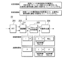
また、図6に示すブロック図のように、図5における復調器202の機能を多次元復調部205と通信路値演算部206に分離して受信装置23を構成しても、同等の効果を実現することができる。この場合、多次元復調部205は、受信信号点から最も確からしい送信時の信号点を判定する処理のみを行っている。通信路値演算部206は、復号化器204から得られる通信路値L3を基にして、通信路値を更新する処理を行っている。そして、初回受信ブロックの処理後に得られた通信路値から、次回受信ブロックに対する事前確率の初期値の推定が行われるが、これは図5における構成の場合と同じである。
Further, as shown in the block diagram of FIG. 6, the same effect can be obtained even if the function of the
さらに、図7に示すブロック図のように、図6における復号化器204と通信路値演算部206を双反復復号化器207に置き換えた受信装置24とすることもできる。図8は、双反復復号化器207の内部構成を示したブロック図である。図8において、通信路値演算部208a・208bは、多次元復調部205で得られた2ビットシンボルabの確からしさPc(ab)、および、復号化器209b・209aで得られたシンボルbの事後値P(b)をそれぞれ用いて、次式に従ってシンボルaの軟判定値Pc(a)を計算して順次更新していく。ここで、AとBは適切な効果を得るために用いる定数または変数であり、その値を1に設定してもよい。
Further, as shown in the block diagram of FIG. 7, the receiving
![]()
![]()
以上、図面を参照してこの発明の一実施形態について詳しく説明してきたが、具体的な構成は上述のものに限られることはなく、この発明の要旨を逸脱しない範囲内において様々な設計変更等をすることが可能である。
例えば、上述したいずれかの送信装置または受信装置を用いてデジタル信号伝送を行う場合において、受信装置が全てのブロックの受信を完了する前に、それまでに受信し復号した結果から伝送された情報ビットが正しく復号されたことが分かったときは、その旨を送信装置に通知して残りのブロックの送信を中止させるような制御を取り入れてもよい。このようにすれば、無駄なブロックが伝送されることを避けることができるので、伝送効率がさらに向上する。また逆に、伝送された情報ビットが正しく復号されなかったときに送信装置に通知して残りのブロックを送信させるよう制御を行ってもよい。
As described above, the embodiment of the present invention has been described in detail with reference to the drawings. However, the specific configuration is not limited to the above, and various design changes and the like can be made without departing from the scope of the present invention. It is possible to
For example, in the case where digital signal transmission is performed using any of the above-described transmission devices or reception devices, the information transmitted from the result of reception and decoding before the reception device completes reception of all blocks. When it is found that the bits have been correctly decoded, it is possible to adopt a control for notifying the transmitting device to that effect and stopping the transmission of the remaining blocks. In this way, it is possible to avoid transmission of useless blocks, thereby further improving the transmission efficiency. Conversely, control may be performed to notify the transmitting device when the transmitted information bits are not correctly decoded and to transmit the remaining blocks.
10、11、30〜32…送信装置 20〜24、40、41…受信装置 101、301…符号化器 102、303…変調器 103…シリアルパラレル変換器 104…拡散多重化器 105…逆高速フーリエ変換器 106、304…メモリ 201…高速フーリエ変換器 202、401…復調器 203、402…ブロック合成回路 204、209a、209b、403…復号化器 205…多次元復調部 206、208a、208b…通信路値演算部 207…双反復復号化器 302…バッファ
DESCRIPTION OF
Claims (4)
前記分割された全てのブロックを受信する前に復号を開始して、まだ受信していない未受信ブロックに含まれる変調シンボルの受信確率を、復号済みの変調シンボルの受信確率に基づいて予測し、
前記未受信ブロックを受信して該ブロックに含まれる変調シンボルを復調するとき、前記予測された受信確率に基づいて通信路値を求め、
前記復調の機能として、多次元復調の機能と通信路値演算の機能を有し、
前記通信路値演算の機能は、前記通信路値を次の式により演算し、
P(b)とP(b’)は前記受信確率の初期値であり、前記通信路値演算の機能は、初回の受信ブロックの処理時には該初期値を1/2とし、次回の受信ブロックの処理時には該初期値を初回の受信ブロックの処理時の結果とする
ことを特徴とするデジタル信号伝送方法。 A digital signal transmission method that modulates a codeword obtained by encoding information bits to be transmitted, divides a modulation symbol obtained by the modulation into two or more blocks, and transmits the block.
Decoding is started before receiving all the divided blocks, and the reception probability of modulation symbols included in an unreceived block that has not yet been received is predicted based on the reception probability of decoded modulation symbols;
When receiving the unreceived block and demodulating a modulation symbol included in the block, a channel value is obtained based on the predicted reception probability ,
As the demodulation function, it has a multi-dimensional demodulation function and a channel value calculation function,
The function of the channel value calculation is to calculate the channel value according to the following equation:
P (b) and P (b ′) are initial values of the reception probability, and the function of the channel value calculation is to halve the initial value when processing the first received block, The digital signal transmission method according to claim 1, wherein the initial value is used as a result of processing the first received block at the time of processing .
ことを特徴とするデジタル信号伝送方法。 In the case of performing transmission and / or reception using the digital signal transmission method according to claim 1, before receiving all the divided blocks, the information bits are correctly obtained from the results decoded up to that point. A digital signal transmission method characterized in that, when decoded, notifies the transmission side to stop transmission of the remaining blocks.
ことを特徴とするデジタル信号伝送方法。 In the case of performing transmission and / or reception using the digital signal transmission method according to any one of claims 1 to 2, before receiving all the divided blocks, decoding is performed up to that point. When the information bits are not correctly decoded from the result, a digital signal transmission method characterized by notifying the transmitting side and transmitting the remaining blocks.
まだ受信していない未受信ブロックに含まれる変調シンボルの受信確率を、復号済みの変調シンボルの受信確率に基づいて予測し、前記未受信ブロックを受信して該ブロックに含まれる変調シンボルを復調するとき、前記予測された受信確率に基づいて通信路値を求める復調手段を備え、
前記復調の機能として、多次元復調の機能と通信路値演算の機能を有し、
前記通信路値演算の機能は、前記通信路値を次の式により演算し、
P(b)とP(b’)は前記受信確率の初期値であり、前記通信路値演算の機能は、初回の受信ブロックの処理時には該初期値を1/2とし、次回の受信ブロックの処理時には該初期値を初回の受信ブロックの処理時の結果とする
ことを特徴とする受信装置。 In digital signal transmission in which a code word obtained by encoding information bits to be transmitted is modulated, and a modulation symbol obtained by the modulation is divided into two or more blocks and transmitted.
A reception probability of a modulation symbol included in an unreceived block that has not been received is predicted based on a reception probability of a decoded modulation symbol, and the modulation symbol included in the block is demodulated by receiving the unreceived block. A demodulation means for obtaining a channel value based on the predicted reception probability ,
As the demodulation function, it has a multi-dimensional demodulation function and a channel value calculation function,
The function of the channel value calculation is to calculate the channel value according to the following equation:
P (b) and P (b ′) are initial values of the reception probability, and the function of the channel value calculation is to halve the initial value when processing the first received block, The receiving apparatus , wherein the initial value is used as a result of processing the first received block at the time of processing .
Priority Applications (1)
| Application Number | Priority Date | Filing Date | Title |
|---|---|---|---|
| JP2010199285A JP5154621B2 (en) | 2010-09-06 | 2010-09-06 | Digital signal transmission method and receiver |
Applications Claiming Priority (1)
| Application Number | Priority Date | Filing Date | Title |
|---|---|---|---|
| JP2010199285A JP5154621B2 (en) | 2010-09-06 | 2010-09-06 | Digital signal transmission method and receiver |
Related Parent Applications (1)
| Application Number | Title | Priority Date | Filing Date |
|---|---|---|---|
| JP2005315493A Division JP4606995B2 (en) | 2005-10-28 | 2005-10-28 | Digital signal transmission method and transmitter |
Publications (2)
| Publication Number | Publication Date |
|---|---|
| JP2011019278A JP2011019278A (en) | 2011-01-27 |
| JP5154621B2 true JP5154621B2 (en) | 2013-02-27 |
Family
ID=43596649
Family Applications (1)
| Application Number | Title | Priority Date | Filing Date |
|---|---|---|---|
| JP2010199285A Expired - Fee Related JP5154621B2 (en) | 2010-09-06 | 2010-09-06 | Digital signal transmission method and receiver |
Country Status (1)
| Country | Link |
|---|---|
| JP (1) | JP5154621B2 (en) |
Families Citing this family (1)
| Publication number | Priority date | Publication date | Assignee | Title |
|---|---|---|---|---|
| WO2019095362A1 (en) * | 2017-11-20 | 2019-05-23 | Qualcomm Incorporated | Techniques and apparatuses for hybrid automatic repeat request design of polar codes for ultra-reliable low latency communications |
Family Cites Families (6)
| Publication number | Priority date | Publication date | Assignee | Title |
|---|---|---|---|---|
| US7106813B1 (en) * | 2000-03-16 | 2006-09-12 | Qualcomm, Incorporated | Method and apparatus for combined soft-decision based interference cancellation and decoding |
| JP3464649B2 (en) * | 2000-12-27 | 2003-11-10 | 松下電器産業株式会社 | Transmission device, reception device, and communication method |
| JP3545726B2 (en) * | 2001-02-27 | 2004-07-21 | 松下電器産業株式会社 | Receiver device |
| JP4082257B2 (en) * | 2003-03-25 | 2008-04-30 | 富士通株式会社 | Packet retransmission control method, transmitting apparatus and receiving apparatus |
| JP3785161B2 (en) * | 2003-06-13 | 2006-06-14 | 株式会社東芝 | Communication device and error detection correction method for communication device |
| JP2005192175A (en) * | 2003-12-05 | 2005-07-14 | Hitachi Kokusai Electric Inc | Transmission apparatus and reception apparatus |
-
2010
- 2010-09-06 JP JP2010199285A patent/JP5154621B2/en not_active Expired - Fee Related
Also Published As
| Publication number | Publication date |
|---|---|
| JP2011019278A (en) | 2011-01-27 |
Similar Documents
| Publication | Publication Date | Title |
|---|---|---|
| US10938876B2 (en) | Method and system for low data rate transmission | |
| KR101531413B1 (en) | Radio transmitting device and radio transmitting method | |
| US7782896B2 (en) | Wireless communication apparatus and wireless communication method | |
| KR101259317B1 (en) | Cqi receiving method and integrated circuit | |
| US9178658B2 (en) | System and method for channel interleaver and layer mapping in a communications system | |
| JP5153009B2 (en) | Beam formation by antenna puncture | |
| US7397861B2 (en) | Mapping strategy for OFDM-based systems using H-ARQ | |
| JP5533873B2 (en) | Multiple component carrier OFDMA communication system | |
| JP4781278B2 (en) | RATE MATCHING DEVICE, WIRELESS TRANSMITTING DEVICE, WIRELESS RECEIVING DEVICE, AND RATE MATCHING METHOD | |
| CN105164959A (en) | Method and apparatus for rate matching of polar code | |
| CN105874736A (en) | Polar code rate-matching method and rate-matching device | |
| JP5096208B2 (en) | SC-FDMA transmitter and SC-FDMA transmission signal forming method | |
| JP5568793B2 (en) | Base station apparatus and reception method | |
| CN109644008A (en) | Circular buffer rate for polarization code matches | |
| JP4606995B2 (en) | Digital signal transmission method and transmitter | |
| JP5295270B2 (en) | Transmitting apparatus and transmitting method | |
| US20080008256A1 (en) | Ofdm Transmitting Apparatus, Ofdm Receiving Apparatus, and Their Methods | |
| JP5860885B2 (en) | Transmitting apparatus and transmitting method | |
| JP6866154B2 (en) | Receiver and receiving method | |
| JP5154621B2 (en) | Digital signal transmission method and receiver | |
| CN101248604A (en) | Wireless communication apparatus and wireless communication method | |
| JP2010219748A (en) | Transmitter, communication system, receiver, transmission method, reception method, transmission control program, and reception control program | |
| JP2007013863A (en) | Retransmission apparatus and retransmission method | |
| JP2004364075A (en) | Radio transmitter, and radio transmitting method |
Legal Events
| Date | Code | Title | Description |
|---|---|---|---|
| A977 | Report on retrieval |
Free format text: JAPANESE INTERMEDIATE CODE: A971007 Effective date: 20120517 |
|
| A131 | Notification of reasons for refusal |
Free format text: JAPANESE INTERMEDIATE CODE: A131 Effective date: 20120529 |
|
| A521 | Request for written amendment filed |
Free format text: JAPANESE INTERMEDIATE CODE: A523 Effective date: 20120730 |
|
| A521 | Request for written amendment filed |
Free format text: JAPANESE INTERMEDIATE CODE: A821 Effective date: 20120731 |
|
| TRDD | Decision of grant or rejection written | ||
| A01 | Written decision to grant a patent or to grant a registration (utility model) |
Free format text: JAPANESE INTERMEDIATE CODE: A01 Effective date: 20121127 |
|
| A61 | First payment of annual fees (during grant procedure) |
Free format text: JAPANESE INTERMEDIATE CODE: A61 Effective date: 20121205 |
|
| FPAY | Renewal fee payment (event date is renewal date of database) |
Free format text: PAYMENT UNTIL: 20151214 Year of fee payment: 3 |
|
| R150 | Certificate of patent or registration of utility model |
Ref document number: 5154621 Country of ref document: JP Free format text: JAPANESE INTERMEDIATE CODE: R150 Free format text: JAPANESE INTERMEDIATE CODE: R150 |
|
| LAPS | Cancellation because of no payment of annual fees |