JP5153512B2 - Display processing apparatus, display processing method, program, and storage medium - Google Patents
Display processing apparatus, display processing method, program, and storage medium Download PDFInfo
- Publication number
- JP5153512B2 JP5153512B2 JP2008205980A JP2008205980A JP5153512B2 JP 5153512 B2 JP5153512 B2 JP 5153512B2 JP 2008205980 A JP2008205980 A JP 2008205980A JP 2008205980 A JP2008205980 A JP 2008205980A JP 5153512 B2 JP5153512 B2 JP 5153512B2
- Authority
- JP
- Japan
- Prior art keywords
- setting
- bracket
- value
- display processing
- exposure correction
- Prior art date
- Legal status (The legal status is an assumption and is not a legal conclusion. Google has not performed a legal analysis and makes no representation as to the accuracy of the status listed.)
- Active
Links
Images


Classifications
-
- G—PHYSICS
- G03—PHOTOGRAPHY; CINEMATOGRAPHY; ANALOGOUS TECHNIQUES USING WAVES OTHER THAN OPTICAL WAVES; ELECTROGRAPHY; HOLOGRAPHY
- G03B—APPARATUS OR ARRANGEMENTS FOR TAKING PHOTOGRAPHS OR FOR PROJECTING OR VIEWING THEM; APPARATUS OR ARRANGEMENTS EMPLOYING ANALOGOUS TECHNIQUES USING WAVES OTHER THAN OPTICAL WAVES; ACCESSORIES THEREFOR
- G03B7/00—Control of exposure by setting shutters, diaphragms or filters, separately or conjointly
-
- H—ELECTRICITY
- H04—ELECTRIC COMMUNICATION TECHNIQUE
- H04N—PICTORIAL COMMUNICATION, e.g. TELEVISION
- H04N23/00—Cameras or camera modules comprising electronic image sensors; Control thereof
- H04N23/70—Circuitry for compensating brightness variation in the scene
- H04N23/743—Bracketing, i.e. taking a series of images with varying exposure conditions
Description
本発明は、デジタルカメラ等の撮像装置に係る表示処理装置等に関し、特に、撮影条件補正値および該撮影条件補正におけるブラケット値の設定技術に関する。 The present invention relates to a display processing apparatus and the like related to an imaging apparatus such as a digital camera, and more particularly to a shooting condition correction value and a technique for setting a bracket value in the shooting condition correction.
従来、デジタルカメラ等の撮像装置において、撮像装置が自動的に設定した適正露出値をユーザが補正する露出補正機能を備えたものが実現されている。また、撮像装置が自動的に設定した露出値、又はユーザが設定した露出補正値を中心としてオーバー側、アンダー側に自動的に露出値を補正して複数コマを撮影するオートブラケット(AEB)機能を備えた撮像装置も実現されている。 2. Description of the Related Art Conventionally, an imaging apparatus such as a digital camera has been provided with an exposure correction function for a user to correct an appropriate exposure value automatically set by the imaging apparatus. Also, an auto bracket (AEB) function that automatically corrects the exposure value to the over side and under side with the exposure value automatically set by the imaging device or the exposure correction value set by the user to shoot a plurality of frames. An image pickup apparatus including the above is also realized.
この種の撮像装置では、一般に、図18(a)に示したような表示画面を参照しながら露出補正値を設定したり、図18(b)に示したような表示画面を参照しながらブラケット値を設定したりすることができる。 In this type of imaging apparatus, generally, an exposure correction value is set with reference to a display screen as shown in FIG. 18A, or a bracket is set with reference to a display screen as shown in FIG. Value can be set.
また、露出補正情報に係る指示部と全てのブラケット段数に係る指示部を対応付けて表示することにより、露出補正情報とオートブラケット撮影回数分の全てのオートブラケット段数を一目で確認できるようにする技術も開発されている(特許文献1参照)。
しかしながら、特許文献1に係る技術では、オートブラケット値を設定する場合に、露出補正を加味した形態での全体的な露出補正可能範囲を確認しながらオートブラケット値を設定することができず、不便であった。
However, in the technique according to
なお、同様の問題は、露出補正に係るオートブラケット機能だけでなく、調光、シャッタ速度、絞り値、ホワイトバランス、ISO感度等の各種の撮影条件に係る適正設定値を補正して複数コマの撮影を自動的に行うオートブラケット機能においても発生していた。 A similar problem is not only caused by the auto bracket function related to exposure correction, but also by correcting the appropriate setting values related to various shooting conditions such as light control, shutter speed, aperture value, white balance, ISO sensitivity, etc. It also occurred in the auto bracket function that automatically shoots.
本発明は、このような技術的な背景の下になされたもので、その目的は、撮影条件の補正を加味した形態での全体的な撮影条件補正可能範囲を確認しながら、オートブラケット値を設定することができるようにすることにある。 The present invention has been made under such a technical background, and the object of the present invention is to set the auto bracket value while confirming the overall range of correction of shooting conditions in a form that takes correction of shooting conditions into account. It is to be able to set.
上記目的を達成するため、本発明は、特定の撮影設定の設定値をユーザからの指示に基づいて補正した補正値に設定する補正設定手段と、オートブラケット撮影におけるブラケット値をユーザからの指示に基づいて設定するブラケット値設定手段と、前記補正設定手段と前記ブラケット値設定手段とで設定可能な値の範囲を示す目盛りと、前記補正設定手段で設定可能な値の範囲を示し、前記目盛りと対応付けて配列される第1の指標と、前記ブラケット値設定手段で設定可能な値の範囲を示し、前記第1の指標が表示される位置とは異なる位置に前記目盛り及び前記第1の指標と対応付けて配列される第2の指標とを、同一画面上に表示するための処理を行う表示処理手段と、を有することを特徴とする。 In order to achieve the above object, the present invention provides a correction setting means for setting a set value of a specific shooting setting to a correction value corrected based on an instruction from a user, and a bracket value in auto bracket shooting based on an instruction from the user. Bracket value setting means for setting based on, a scale indicating a range of values that can be set by the correction setting means and the bracket value setting means, a range of values that can be set by the correction setting means, and the scale The first index arranged in association with the bracket and the range of values that can be set by the bracket value setting means, and the scale and the first index at a position different from the position where the first index is displayed And display processing means for performing processing for displaying the second index arranged in association with each other on the same screen .
本発明によれば、撮影条件補正機能とオートブラケット機能を併用した場合に設定可能な全ての設定値に係る目盛りと対応付けて、設定可能な全ての撮影条件補正値に係る指標と設定可能な全てのブラケット値に係る指標とが表示される。 According to the present invention, it is possible to set an index related to all settable shooting condition correction values in association with the scales related to all settable values when the shooting condition correction function and the auto bracket function are used together. Indicators related to all bracket values are displayed.
従って、撮影条件の補正を加味した形態での全体的な撮影条件補正可能範囲を確認しながら、オートブラケット値を設定することが可能となる。 Accordingly, it is possible to set the auto bracket value while confirming the overall range for correcting the shooting condition in a form that takes correction of the shooting condition into consideration.
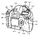
以下、本発明を実施するための最良の形態を図面に基づいて説明する。図1は、本発明の実施の形態に係る撮像装置の外観図、図2は、図1に示した撮像装置の内部構成図である。図1,2に示した撮像装置は、デジタル一眼レフカメラ(以下、カメラ本体という)100として構成されている。 Hereinafter, the best mode for carrying out the present invention will be described with reference to the drawings. FIG. 1 is an external view of an image pickup apparatus according to an embodiment of the present invention, and FIG. 2 is an internal configuration diagram of the image pickup apparatus shown in FIG. The imaging apparatus shown in FIGS. 1 and 2 is configured as a digital single-lens reflex camera (hereinafter referred to as a camera body) 100.
カメラ本体100の上部には、アクセサリシュー110、光学ファインダ104、AE(自動露出)ロックボタン112、焦点検出領域選択ボタン113、レリーズボタン114が設けられている。さらに、カメラ本体100の上部には、メイン電子ダイヤル411、モードダイヤル60、外部表示ユニット409も設けられている。
An
AE(自動露出)ロックボタン112は、例えば、スポット測光で得られた適正露出値に露出値を固定して撮影する場合に用いられる。焦点検出領域選択ボタン113は、AF(自動合焦)制御における焦点検出領域を選択するために用いられる。レリーズボタン114は、撮像動作を指示するために用いられる。
The AE (automatic exposure)
メイン電子ダイヤル411は、他の操作ボタンと共に操作されることによって、カメラ動作に関する数値を入力したり撮像モードを切換えたりするために用いられる。外部表示ユニット409は、液晶パネル等により構成され、シャッタ速度値、絞り値、撮像モード等の撮影条件その他の情報を表示する。
The main
カメラ本体100の背面には、LCDモニタユニット417、再生ボタン66、メニューボタン68、サブ電子ダイヤル116、SETボタン117、電源スイッチ72が設けられている。また、不図示であるが十字キーやマルチコントローラー等の操作部材も設けられている。
An
LCDモニタユニット417は、撮影により得られた画像(画像データ)や各種設定画面等を表示するために利用される。LCDモニタユニット417は、透過型LCDで構成され、バックライト416(図2参照)を有している。なお、LCDモニタユニット417は、本撮像装置で設定或いは処理可能な各種の設定、処理等を指定するためのメニュー画面や、後述する露出補正/AEB設定画面(GUI画面:図14参照)を表示する表示器としても利用される。再生ボタン66は、撮影した画像をLCDモニタユニット417に再生表示させる際に利用される。
The
メニューボタン68は、LCDモニタユニット417にカメラの各種設定を行うためのメニュー画面を表示させるために利用される。例えば、撮影モードを設定する場合は、このメニューボタン68を押下した後、サブ電子ダイヤル116を操作して所望のモードを選択し、所望のモードが選択された状態でSETボタン117を押下することにより、撮影モードの設定が完了する。
The
なお、図14の露出補正/AEB設定画面に遷移する場合は、上記のメニュー画面を表示した後、サブ電子ダイヤル116及びメイン電子ダイヤル411で露出補正/AEB設定を選択した状態でSETボタン117を押下すればよい。
When transitioning to the exposure correction / AEB setting screen of FIG. 14, after the above menu screen is displayed, the
カメラ本体100の前面にはマウント106(図3参照)が設けられており、このマウント106には、交換レンズ300に設けられたマウント306が着脱可能に結合される。図2において、401は撮像光軸を示している。交換レンズ300には、複数のレンズにより構成されるレンズユニット310、絞り312が設けられている。
A mount 106 (see FIG. 3) is provided on the front surface of the
また、カメラ本体100の内部において、ミラー130が撮像光路内に配置されている。このミラー130は、レンズユニット310からの被写体光をファインダ光学系に向けて反射する位置(図2に示す位置)と、撮像光路外に退避する位置との間で移動可能となっている。ピント板204上には、ミラー130で反射された被写体光によって被写体像が形成される。
In addition, a
205はファインダの視認性を向上させるためのコンデンサレンズ、132はペンタゴナルダハプリズムである。ペンタゴナルダハプリズム132は、ピント板204及びコンデンサレンズ205を通った被写体光を接眼レンズ208に導く。これらピント板204〜接眼レンズ208によって光学ファインダ104が構成される。ユーザは、ピント板204上に形成された被写体像を接眼レンズ208を通して観察することができる。
209,210は、それぞれ、フォーカルプレンシャッタ12(図3参照)を構成する後幕と先幕である。これら後幕209及び先幕210の開放制御により、撮像素子14が必要な時間だけ露光される。撮像素子14は、CCDセンサやCMOSセンサにより構成され、その前面には光学ローパスフィルタ418が配設されている。
また、撮像素子14は、プリント基板211に接続されている。このプリント基板211の後方には、表示基板215が配置されている。表示基板215の反対側の面には、LCDモニタユニット417及びバックライト416が配置されている。
Further, the
200は撮像動作で得られた画像データを記録する記録媒体であり、半導体メモリやハードディスク等により構成される。86は二次電池である。記録媒体200及び電池86は、カメラ本体100に対して着脱が可能である。
次に、カメラ本体100及び交換レンズ300の回路構成を図3に基づいて説明する。
なお、図3において、図1及び図2に示した構成要素については、図1及び図2と同一の符号を付している。
Next, circuit configurations of the
In FIG. 3, the same reference numerals as those in FIGS. 1 and 2 are assigned to the components shown in FIGS.
まず、交換レンズ300内の回路構成について説明する。交換レンズ300には、この交換レンズ300をカメラ本体100と電気的に接続するためのコネクタ322及びインターフェース320が設けられている。コネクタ322及びインターフェース320は、カメラ本体100に設けられたコネクタ122及びインターフェース120を介して、後述するレンズシステム制御回路350とカメラ本体100内のシステム制御回路50との通信を可能とする。
First, a circuit configuration in the
絞り制御部340は、絞り312を制御する制御部である。絞り制御部340は、後述する測光制御部46からの測光情報に基づいて、シャッタ制御部40と連携しながら絞り312を制御する。フォーカス制御部342は、レンズユニット310のフォーカス動作を制御する。ズーム制御部344は、レンズユニット310の変倍動作を制御する。
The
レンズシステム制御回路350は、交換レンズ300の各種動作を全体的に制御する。レンズシステム制御回路350は、各種動作用の定数、変数、コンピュータプログラム等を記憶するメモリを備えている。
The lens
次に、カメラ本体100内の回路構成について説明する。レンズユニット310及び絞り312を通過した被写体光は、ミラー130が撮像光路外に退避した状態(ミラー130がハーフミラーである場合は撮像光路内に配置された状態)で、開放されたフォーカルプレンシャッタ12を通過して撮像素子14に入射される。撮像素子14は、入射された被写体光を光電変換し、アナログの画像信号として出力する。
Next, a circuit configuration in the
A/D変換器16は、撮像素子14から出力されるアナログ信号(画像信号)をデジタル信号に変換する。タイミング発生回路18は、メモリ制御回路22及びシステム制御回路50の制御の下に、撮像素子14、A/D変換器16及びD/A変換器26にクロック信号や制御信号を供給する。
The A /
画像処理回路20は、A/D変換器16からの画像データ又はメモリ制御回路22からの画像データに対して、画素補間処理や色変換処理を行う。また、画像処理回路20は、A/D変換器16から出力される画像データを用いて所定の演算処理を行う。システム制御回路50は、この演算結果に基づいて、シャッタ制御部40及び焦点調節部42を制御するためのTTL方式のオートフォーカス(AF)処理、自動露出(AE)処理及びフラッシュプリ発光(EF)処理を行う。
The
さらに、画像処理回路20は、A/D変換器16から出力される画像データを用いて所定の演算処理を行い、この演算結果に基づいてTTL方式のオートホワイトバランス(AWB)処理も行う。
Further, the
メモリ制御回路22は、A/D変換器16、タイミング発生回路18、画像処理回路20、画像表示メモリ24、D/A変換器26、メモリ30及び圧縮・伸長回路32を制御する。A/D変換器16から出力された画像データは、画像処理回路20及びメモリ制御回路22を介して、又はメモリ制御回路22のみを介して画像表示メモリ24又はメモリ30に書き込まれる。
The
画像表示部28は、D/A変換器26によりアナログ信号に変換され、画像表示メモリ24に書き込まれた画像信号を、図1及び図2に示したLCDモニタユニット417に逐次表示することで、電子ビューファインダ(EVF)機能を実現する。なお、画像表示部28は、システム制御回路50の指示により、電子ビューファインダ(EVF)機能をON/OFFする。
The
メモリ30は、撮像に係る静止画像を格納する。また、メモリ30は、動画撮影時に所定レートで連続的に記録媒体200、付属装置210書き込まれる画像のフレームバッファとして使用される。さらに、メモリ30は、システム制御回路50の作業領域としても使用される。
The
圧縮・伸長回路32は、公知の画像圧縮方法を用いて画像データを圧縮・伸長する。圧縮・伸長回路32は、メモリ30に格納された画像を読み込んで圧縮処理又は伸長処理を行い、処理を終えたデータを再びメモリ30に書き込む。
The compression /
シャッタ制御部40は、測光制御部46からの測光情報に基づいて、絞り制御部340と連携しながら、フォーカルプレンシャッタ12のシャッタ速度を制御する。
The shutter control unit 40 controls the shutter speed of the
焦点調節部42は、ミラー130を透過して不図示のサブミラーによって導かれた被写体像の位相差を検出することで、AF(オートフォーカス)処理を行う。測光制御部46は、不図示の測光センサからの出力信号に基づいて、AE(自動露出)処理を行う。
The focus adjustment unit 42 performs AF (autofocus) processing by detecting a phase difference of a subject image that is transmitted through the
フラッシュ48は、AF補助光の投光機能やフラッシュ調光機能を有する。なお、測光制御部46は、フラッシュ48と連携して、EF(フラッシュ調光)処理を行う。
The
システム制御回路50は、CPUやメモリを含み、カメラ本体100の動作を全体的に制御する。メモリ52には、システム制御回路50の動作用の定数、変数、コンピュータプログラム(基本プログラム)等が記憶される。
The
通知部54は、システム制御回路50でのコンピュータプログラムの実行に応じて、文字、画像をLCDやLED等により表示したり、音声をスピーカ(図示省略)から発したりして、カメラの動作状態やメッセージ等を外部に通知する。この通知部54には、光学ファインダ104内に絞り値、シャッタ速度、合焦度、手振れ警告、露出補正値等の表示を行うLCDユニットが含まれる。
The
不揮発性メモリ56は、例えば電気的に消去・記録可能なEEPROM等で構成され、コンピュータプログラム等の格納用メモリとして使用される。この場合、当然ながら、コンピュータプログラムは、コンピュータ読取可能に不揮発性メモリ56に格納される。
このコンピュータプログラムには、後述する図4〜図13のフローチャートに係るコンピュータ実行可能に構成されたアプリケーションプログラムが含まれる。不揮発性メモリ56には、メニュー画面、露出補正/AEB設定画面等のGUI画面上で設定された設定値、メイン電子ダイヤル411、サブ電子ダイヤル116の操作で設定された設定値、モードダイヤル60の操作で指定された撮影モード情報等も格納される。
The
This computer program includes an application program configured to be computer-executable according to the flowcharts of FIGS. The
シャッタスイッチ(SW1)62は、レリーズボタン114の第1ストローク操作(半押し)によってONとなり、AF処理、AE処理、AWB処理、EF処理等の動作開始をシステム制御回路50に指示する。シャッタスイッチ(SW2)64は、レリーズボタン114の第2ストローク操作(全押し)によってONとなり、露光処理、現像処理及び記録処理からなる一連の撮像処理の動作開始をシステム制御回路50に指示する。
The shutter switch (SW1) 62 is turned on by the first stroke operation (half-press) of the
再生ボタン66は、撮影に係る画像データをメモリ30あるいは記録媒体200、他の付属装置210から読出して画像表示部28(LCDユニット417)に表示する再生動作の開始をシステム制御回路50に指示するために操作される。
The
メニューボタン68は、メニュー画面の表示をシステム制御回路50に指示するために操作される。システム制御回路50は、メニュー画面の表示指示を受けて、撮影条件等を不揮発性メモリ56から読み出してメニュー画面を作成し、LCDユニット417に表示する。
The
操作部70は、再生ボタン66、メニューボタン68などの各種ボタンや、メイン電子ダイヤル411、サブ電子ダイヤル116、モードダイヤル60などの各種ダイヤルを含む。システム制御回路50は、操作部70からの信号に応じて各種動作を行う。
The
電源スイッチ72は、カメラ本体100の電源のオン/オフを切換えるためのスイッチである。また、電源スイッチ72の操作によって、カメラ本体100に接続された交換レンズ300、外部フラッシュ115、記録媒体200及び他の付属装置(パーソナルコンピュータ等)210の電源のオン/オフも同時に切換えることができる。
The
電源制御部80は、電池検出回路、DC−DCコンバータ、通電するブロックを切換えるスイッチ回路等により構成されている。電源制御部80は、電池の装着の有無、電池の種類及び電池残量の検出を行い、その検出結果及びシステム制御回路50の指示に基づいてDC−DCコンバータを制御し、必要な電圧を必要な期間、記録媒体200を含む各部に供給する。
The power
コネクタ82,84は、電池等の電源86からの電力をカメラ本体100、交換レンズ300、外部フラッシュ115、記録媒体200及び他の付属装置210に供給する。90,94は記録媒体200及び付属装置210のインターフェースであり、92,96は記録媒体200や付属装置210との接続を行うコネクタである。98はコネクタ92,96に記録媒体200や付属装置210が装着されているか否かを検出する着脱検出回路である。
The
次に、画像表示部28(LCDユニット417)に表示される露出補正/AEB設定画面を、図14〜図16に基づいて説明する。この露出補正/AEB設定画面の表示処理は、不揮発性メモリ56に格納されたアプリケーションプログラムをシステム制御部50が実行することにより行われる。
Next, an exposure correction / AEB setting screen displayed on the image display unit 28 (LCD unit 417) will be described with reference to FIGS. The exposure correction / AEB setting screen display process is performed by the
まず、図14に基づいて、露出補正/AEB設定画面の概要を説明する。図14に示したように、露出補正/AEB設定画面には、目盛り1405、露出補正設定可能範囲1406、ブラケット設定可能範囲1407が対応付けて表示される。
First, an outline of the exposure correction / AEB setting screen will be described with reference to FIG. As shown in FIG. 14, a
目盛り1405には、測光情報に基づいてシステム制御部50が算出した適正露出値を基準値「0」1414として、露出補正機能とオートブラケット(AEB)機能を併用した場合に設定可能な全ての露出値に係る目盛りが刻まれている。
The
従って、目盛り1405と、露出補正設定可能範囲1406と、ブラケット設定可能範囲1407とを対応付けて表示することにより、露出補正を加味した形態での全体的な露出補正可能範囲を確認しながら、オートブラケット値を設定することが可能となる。換言すれば、撮影条件の補正を加味した形態での全体的な撮影条件補正可能範囲を確認しながら、オートブラケット値を設定することが可能となる。
Accordingly, by displaying the
上記の目盛り1405は、AEB設定画面の所定位置に固定的に表示される。ただし、目盛りの数、すなわち設定可能な露出補正値の全体の数は、AEB機能を用いる場合と用いない場合とで異なる。しかし、AEB機能を用いる場合と用いない場合の何れの場合も、露出オーバー側の目盛りの数と露出アンダー側の目盛りの数は同数となっている。
The
また、適正露出値に対応する基準値「0」1414は、一目で識別可能なように、他の露出値とは異なる特殊な形態で表示される。さらに、目盛り1405においては、整数の露出値は、その露出値に対応する数字で示され、各整数の露出値間の小数点以下の数値を含む露出値は、○印で示されている。
Further, the reference value “0” 1414 corresponding to the appropriate exposure value is displayed in a special form different from other exposure values so that it can be identified at a glance. Further, on the
さらに、オーバー側の目盛りの上部には、符号1413で示したように「明るく」という文字列が表示され、アンダー側の目盛りの上部には、符号1412で示したように「暗く」という文字列が表示される。これら文字列の表示により、ユーザは、思考を廻らすことなく、瞬時に、これから行う露出補正値、ブラケット値の設定の効果を認識することが可能となる。
Further, a character string “brighter” is displayed on the upper side scale as indicated by
露出補正設定可能範囲1406としては、目盛り1405に刻まれた目盛りと対応する形で、矩形状の複数の指標が表示されている。ブラケット設定可能範囲1407としては、目盛り1405に刻まれた目盛り、及び露出補正設定可能範囲1406の指標と対応する形で、矩形状の複数の指標が表示されている。
As the exposure
露出補正値が設定(指定)された場合は、その露出補正値に対応する露出補正設定可能範囲1406の指標に対して、露出補正カーソル1409が点灯表示される。また、「0」以外のブラケット値が設定(指定)された場合は、その設定に係るブラケット値に対応するブラケット設定可能範囲1407の指標に対して、ブラケットカーソル1408,1410が表示される。この場合、通常は、アンダー側ブラケットカーソル1408と、オーバー側ブラケットカーソル1410の2つのブラケットカーソルが点灯表示される。
When the exposure correction value is set (designated), the
なお、「0」以外のブラケット値が設定(指定)された場合は、露出補正カーソル1409は、ブラケット設定可能範囲1407の中央の指標に跨って点灯表示される。これは、ブラケット設定可能範囲1407の中央の指標は、常に、設定された露出補正値に係る指標と対向しており、設定に係る露出補正値の変化に連動してブラケット設定可能範囲1407と一体になって移動することを意味する。この移動により、露出補正値を設定した後にオートブラケット値を設定しようとするときに、そのオートブラケット値の設定によって全体的な露出値がどのように変化するかを、瞬間的に認識することが可能となる。
When a bracket value other than “0” is set (designated), the
また、露出補正設定可能範囲1406の表示領域の近傍(左横の位置)には、露出補正設定可能範囲1406の指標が露出補正に係るものである旨をユーザに知らしめるべく、「+/−」アイコン1401がガイダンス表示される。
In addition, in the vicinity of the display area of the exposure correction setting possible range 1406 (position on the left side), “+/− is used in order to inform the user that the index of the exposure correction setting
また、露出補正設定可能範囲1406の表示領域の近傍(右横の位置)には、露出補正値を設定するための操作部材を示すガイダンス用のアイコン、すなわち、サブ電子ダイヤル116の形状をしたガイダンスアイコン1403が表示される。このガイダンスアイコン1403によって、サブ電子ダイヤル116を操作することで露出補正値に係る指標を指定(設定)することができることを、ユーザが容易に認識できる。
Further, in the vicinity of the display area of the exposure correction setting possible range 1406 (right side position), a guidance icon indicating an operation member for setting an exposure correction value, that is, a guidance having the shape of the sub
ブラケット設定可能範囲1407の表示領域の近傍(左横の位置)には、ブラケット設定可能範囲1407の指標がブラケットに係るものである旨をユーザに知らしめるべく、「AEB」アイコン1402が表示される。
In the vicinity of the display region of the bracket settable range 1407 (left lateral position), so the index of the bracket settable range 1407 notify the user that those of the bracket, "AEB"
また、ブラケット設定可能範囲1407の表示領域の近傍(右横の位置)には、ブラケット値を設定するための操作部材を示すために、メイン電子ダイヤル411の形状をしたガイダンスアイコン1404が表示される。このガイダンスアイコン1404によって、メイン電子ダイヤル411を操作することでブラケット値に係る指標を指定(設定)することができることを、ユーザが容易に認識できる。
In the vicinity of the display region of the bracket settable range 1407 (right side position), to indicate the operation member for setting the bracket value,
次に、ブラケット値が「0」の場合の露出補正/AEB設定画面を、図15に基づいて説明する。 Next, an exposure correction / AEB setting screen when the bracket value is “0” will be described with reference to FIG.
ブラケット値が「0」の場合、すなわち、ブラケット機能を用いない場合は、露出補正は、露出補正機能だけを用いて行なわれる。換言すれば、ブラケット機能を用いない場合は、露出補正機能とオートブラケット(AEB)機能を併用した場合に設定可能な全ての露出値は、露出補正機能で設定可能な露出値だけとなる。 When the bracket value is “0”, that is, when the bracket function is not used, exposure correction is performed using only the exposure correction function. In other words, when the bracket function is not used, all the exposure values that can be set when the exposure correction function and the auto bracket (AEB) function are used together are only exposure values that can be set by the exposure correction function.
従って、ブラケット値が「0」の場合の露出補正/AEB設定画面では、図15(a)に示したように、目盛り1501としては、露出補正機能で設定可能な露出値(−2EV〜+2EV)に係る目盛りだけが刻まれている。
Therefore, in the exposure correction / AEB setting screen when the bracket value is “0”, as shown in FIG. 15A, the
また、ブラケット値が「0」の場合は、ブラケット設定可能範囲は非表示となり、露出補正設定可能範囲1502の指標だけが表示される。これにより、ブラケット値の誤った設定操作、或いは無効処理される無駄なブラケット値の設定操作を低減することが可能となる。 When the bracket value is “0”, the bracket settable range is not displayed and only the index of the exposure correction settable range 1502 is displayed. Thereby, it is possible to reduce an erroneous setting operation of the bracket value or a useless setting operation of the bracket value which is invalidated.
なお、図15(a)は、露出補正のステップが1/3段の場合の露出補正/AEB設定画面を示し、目盛り1504及び露出補正設定可能範囲1505の指標は、1/3段の刻み(整数の露出値間の○印、指標が2つ)で表示されている。露出補正のステップが1/2段の場合は、図15(b)に示したように、目盛り1504、及び上記の指標は、1/2段の刻み(整数の露出値間の○印、指標が1つ)で表示される。 FIG. 15A shows an exposure correction / AEB setting screen when the exposure correction step is 1/3 step, and the scale 1504 and the exposure correction settable range 1505 are in steps of 1/3 step ( A circle between integer exposure values and two indices are displayed. When the exposure correction step is ½ step, as shown in FIG. 15B, the scale 1504 and the above-described index are in ½ step increments (marks ○ between integer exposure values, indicators) Is one).
次に、ブラケット値が「0」以外の場合の露出補正/AEB設定画面を、図16に基づいて説明する。 Next, an exposure correction / AEB setting screen when the bracket value is other than “0” will be described with reference to FIG.
ブラケット値が「0」以外の場合、すなわち、ブラケット機能を用いる場合は、露出補正は、露出補正機能とオートブラケット機能の双方を用いて行なわれる。従って、オートブラケット機能を用いる場合、すなわち、露出補正機能とオートブラケット(AEB)機能を併用した場合において設定可能な全ての露出値は、露出補正機能とオートブラケット機能とで設定可能な露出値を合わせたものとなる。 When the bracket value is other than “0”, that is, when the bracket function is used, exposure correction is performed using both the exposure correction function and the auto bracket function. Therefore, when the auto bracket function is used, that is, when the exposure compensation function and the auto bracket (AEB) function are used together, all exposure values that can be set are exposure values that can be set by the exposure compensation function and the auto bracket function. Combined.
従って、ブラケット値が「0」以外の場合の露出補正/AEB設定画面では、図16(a)に示したように、目盛り1601としては、露出値(−4EV〜+4EV)に係る目盛りが刻まれている。この露出値(−4EV〜+4EV)は、露出補正機能で設定可能な露出値(−2EV〜+2EV)とオートブラケット機能で設定可能な露出値(−2EV〜+2EV)を合わせたものである。 Accordingly, in the exposure correction / AEB setting screen when the bracket value is other than “0”, as shown in FIG. 16A, the scale related to the exposure value (−4 EV to +4 EV) is engraved as the scale 1601. ing. This exposure value (−4 EV to +4 EV) is a combination of the exposure value (−2 EV to +2 EV) that can be set with the exposure correction function and the exposure value (−2 EV to +2 EV) that can be set with the auto bracket function.
また、ブラケット値が「0」以外の場合は、ブラケット設定可能範囲1606の指標も露出補正設定可能範囲1605の指標と共に表示される。なお、図16(a)は、露出補正のステップが1/3段の場合の露出補正/AEB設定画面を示し、目盛り1601、露出補正設定可能範囲1605及びオートブラケット設定可能範囲1606の指標は、1/3段の刻みで配列されて表示されている。露出補正のステップが1/2段の場合は、図16(b)に示したように、上記の目盛り、指標は、1/2段の刻みで配列されて表示される。
When the bracket value is other than “0”, the index of the
次に、露出補正/AEB設定画面の表示処理の概要を、図4のフローチャートに基づいて説明する。なお、図4等のフローチャートにおいて、S401等、数字の前に英字「S」が付されたものは、処理のステップ番号を示している。また、図4のS401、S402、S403、S404、S405、S406の処理の詳細は、それぞれ、図5、図6、図7、図8、図9、図10のフローチャートに基づいて後で説明する。さらに、図4、図12、図13では、便宜上、目盛り等を示す符号は、図14で付した符号を用いている。 Next, an overview of the exposure correction / AEB setting screen display process will be described based on the flowchart of FIG. In the flowchart of FIG. 4 or the like, the letter “S” preceded by a number, such as S401, indicates a process step number. Details of the processing of S401, S402, S403, S404, S405, and S406 of FIG. 4 will be described later based on the flowcharts of FIGS. 5, 6, 7, 8, 9, and 10, respectively. . Furthermore, in FIG. 4, FIG. 12, and FIG. 13, for convenience, the reference numerals used in FIG.
ユーザが前述のメニュー画面を介して露出補正/AEB設定の指示を行うと、システム制御回路50は、露出補正/AEB設定の表示に必要なデータを不揮発性メモリ56から取得する(S401)。この必要なデータとしては、数値に係る文字パターンデータ、アイコンパターンデータ等の他に、ユーザが露出補正/AEB設定の指示を行う前に設定した撮影モード、露出補正値のステップ段数等のデータがある。また、必要なデータとしては、ブラケット値、システム制御回路50が測光情報等に基づいて算出したシャッタ速度、絞り値等のデータもある。
When the user gives an instruction for exposure correction / AEB setting via the menu screen described above, the
次に、システム制御回路50は、取得した上記のブラケット値、ステップ段数等のデータに基づいて、目盛り1405を表示する(S402)。次に、システム制御回路50は、露出補正設定可能範囲1406の指標、ブラケット設定可能範囲1407の指標を表示する(S403、S404)。
Next, the
次に、システム制御回路50は、シャッタ速度値と絞り値に基づいて算出した露出補正値、又はユーザが設定した露出補正値に基づいて、露出補正カーソル1409を表示する(S405)。さらに、システム制御回路50は、ユーザが設定したブラケット値に基づいて、アンダー側ブラケットカーソル1408、オーバー側ブラケットカーソル1410を表示する(S405)。
Next, the
そして、システム制御回路50は、ガイダンス情報を表示して(S406)、露出補正/AEB設定画面の表示処理を終了する。表示されるガイダンス情報としては、「+/−」アイコン1401、「AEB」アイコン1402、ガイダンスアイコン1403,1404、文字列「暗く」1412、「明るく」1413がある。
Then, the
次に、図4のS401におけるデータ取得処理の詳細を、図5のフローチャートに基づいて説明する。 Next, details of the data acquisition processing in S401 of FIG. 4 will be described based on the flowchart of FIG.
データ取得処理では、システム制御回路50は、不揮発性メモリ56から、露出補正値を読み込み(S501)、ブラケット値を読み込み(S502)、露出補正のステップ段数を読み込む(S503)。
In the data acquisition process, the
次に、システム制御回路50は、露出補正設定可能範囲1406の指標を表示するか否かを示す露出補正設定可否フラグに、初期値「可」をセットする(S504)。同様に、システム制御回路50は、ブラケット設定可能範囲1407の指標を表示するか否かを示すブラケット設定可否フラグに、初期値「可」をセットする(S505)。
Next, the
次に、システム制御回路50は、撮影モードを判別する(S506)。その結果、撮影モードが「Bulb」、すなわち長時間露出モードであれば、ブラケット設定可否フラグに「否」をセットし直す(S507)。そして、露出補正設定可否フラグに「否」をセットし直して(S508)、データ取得処理を終了する。
Next, the
このように、ブラケット設定可否フラグ及び露出補正設定可否フラグに「否」がセットされることで、露出補正設定可能範囲1406及びブラケット設定可能範囲1407の指標が共に非表示状態となり、露出補正値及びブラケット値の設定が実質的に不可能となる。
As described above, by setting “not” to the bracket setting enable / disable flag and the exposure correction setting enable / disable flag, both the exposure correction setting enable
撮影モードが「M」、すなわちマニュアルモードであれば、システム制御回路50は、露出補正値の設定を不可能にすべく、露出補正設定可否フラグに「否」をセットし直して(S508)、本処理を終了する。また、撮影モードが「Bulb」、「M」以外のモードであれば、システム制御回路50は、現在、AEB撮影の途中であるか否かを判別する(S509)。
If the photographing mode is “M”, that is, the manual mode, the
その結果、AEB撮影の途中であれば、システム制御回路50は、露出補正値の設定を不可能にすべく、露出補正設定可否フラグに「否」をセットし直して(S508)、本処理を終了する。一方、AEB撮影の途中ではない場合は、システム制御回路50は、上記2つのフラグの変更を一切行うことなく終了することで、露出補正値、及びブラケット値の設定を可能にする。
As a result, if the AEB shooting is in progress, the
次に、図4のS402における目盛り表示処理の詳細を、図6のフローチャートに基づいて説明する。 Next, details of the scale display process in S402 of FIG. 4 will be described based on the flowchart of FIG.
目盛り表示処理では、システム制御回路50は、まず、露出補正のステップ段数を判別する(S601)。その結果、露出補正のステップ段数が「1/2」であれば、システム制御回路50は、ブラケット値を判別する(S602)。その結果、ブラケット値が「0」であれば、システム制御回路50は、−2(EV)から+2(EV)の範囲内で1/2ステップ刻みの目盛りを表示して(S603)、目盛り表示処理を終了する。
In the scale display process, the
一方、ブラケット値が「0」以外であれば、システム制御回路50は、−4(EV)から+4(EV)の範囲内で1/2ステップ刻みの目盛りを表示して(S604)、目盛り表示処理を終了する。
On the other hand, if the bracket value is other than “0”, the
S601にて、露出補正のステップ段数が「1/3」であると判別された場合は、システム制御回路50は、ブラケット値を判別する(S605)。その結果、ブラケット値が「0」であれば、システム制御回路50は、−2(EV)から+2(EV)の範囲内で1/3ステップ刻みの目盛りを表示して(S606)、目盛り表示処理を終了する。
If it is determined in step S601 that the exposure correction step number is “1/3”, the
一方、ブラケット値が「0」以外であれば、システム制御回路50は、−4(EV)から+4(EV)の範囲内で1/3ステップ刻みの目盛りを表示して(S607)、目盛り表示処理を終了する。
On the other hand, if the bracket value is other than “0”, the
次に、図4のS403における露出補正設定可能範囲の表示処理の詳細を、図7のフローチャートに基づいて説明する。 Next, details of the display processing of the exposure correction setting possible range in S403 of FIG. 4 will be described based on the flowchart of FIG.
露出補正設定可能範囲の表示処理では、システム制御回路50は、露出補正設定可否フラグのセット内容を判別する(S701)。その結果、露出補正設定可否フラグが「否」の場合は、システム制御回路50は、露出補正設定可能範囲1406の指標を非表示するという、特殊な表示形態で表示し(S702)、本表示処理を終了する。
In the exposure correction setting range display process, the
一方、露出補正設定可否フラグが「可」の場合は、システム制御回路50は、露出補正のステップ段数を判別する(S703)。その結果、露出補正のステップ段数が「1/2」である場合は、−2(EV)から+2(EV)の範囲内で1/2ステップ刻みで露出補正設定可能範囲1406の指標を表示して(S704)、本表示処理を終了する。
On the other hand, when the exposure correction setting enable / disable flag is “enabled”, the
一方、露出補正のステップ段数が「1/3」である場合は、−2(EV)から+2(EV)の範囲内で1/3ステップ刻みで露出補正設定可能範囲1406の指標を表示して(S705)、本表示処理を終了する。 On the other hand, when the step number of the exposure correction is “1/3”, the index of the exposure correction settable range 1406 is displayed in 1/3 step increments within the range of −2 (EV) to +2 (EV). (S705) This display process is terminated.
次に、図4のS404におけるブラケット設定可能範囲の表示処理の詳細を、図8のフローチャートに基づいて説明する。 Next, details of the display processing of the bracket settable range in S404 of FIG. 4 will be described based on the flowchart of FIG.
ブラケット設定可能範囲の表示処理では、システム制御回路50は、ブラケット設定可否フラグのセット内容を判別する(S801)。その結果、ブラケット設定可否フラグが「否」の場合は、システム制御回路50は、ブラケット設定可能範囲1407の指標を非表示にするという、特殊な表示形態で表示して(S802)、本表示処理を終了する。
In the display process of the bracket setting possible range, the
一方、ブラケット設定可否フラグが「可」の場合は、システム制御回路50は、露出補正のステップ段数を判別する(S803)。その結果、露出補正のステップ段数が「1/2」である場合は、システム制御回路50は、「露出補正値−2」(EV)から「露出補正値+2」(EV)の範囲内で1/2ステップ刻みでブラケット設定可能範囲1407の指標を表示する(S804)。ブラケット設定可能範囲1407の指標を表示すると、本表示処理を終了する。
On the other hand, when the bracket setting enable / disable flag is “enabled”, the
一方、露出補正のステップ段数が「1/3」である場合は、システム制御回路50は、「露出補正値−2」(EV)から「露出補正値+2」(EV)の範囲内で1/3ステップ刻みでブラケット設定可能範囲1407の指標を表示して(S805)、本表示処理を終了する。
On the other hand, when the step number of the exposure correction is “1/3”, the
このように、本実施の形態では、ブラケット設定可能範囲1407の指標の表示範囲を、「露出補正値−2」(EV)から「露出補正値+2」(EV)の範囲内としている。これにより、ブラケット設定可能範囲1407の中央の指標は、常に、露出補正値に係る指標と対向する位置に存在することになる。したがって、ブラケット値を設定する際に、そのブラケット値の設定で露出補正値を加味した全体的な露出補正の効果がどのように変化するかを、瞬時に認識することが可能となる。
Thus, in the present embodiment, the display range of the index of the
換言すれば、露出補正を加味した形態での全体的な露出補正可能範囲を容易に確認しながら、オートブラケット値を設定することが可能となる。 In other words, it is possible to set the auto bracket value while easily confirming the overall exposure correction possible range in a form taking exposure correction into consideration.
次に、図4のS405における露出補正・ブラケット値表示処理の詳細を、図9のフローチャートに基づいて説明する。 Next, details of the exposure correction / bracket value display processing in S405 of FIG. 4 will be described based on the flowchart of FIG.
露出補正・ブラケット値表示処理では、システム制御回路50は、ブラケット設定可否フラグのセット内容を判別する(S901)。その結果、ブラケット設定可否フラグが「否」の場合は、システム制御回路50は、露出補正設定可能範囲1406の露出補正値に係る指標の位置に露出補正カーソル1409を表示して(S902)、本表示処理を終了する。
In the exposure correction / bracket value display process, the
一方、ブラケット設定可否フラグが「可」の場合は、システム制御回路50は、ブラケット設定可能範囲1407の指標のうち、「露出補正値−ブラケット値」に係る指標の位置にアンダー側ブラケットカーソル1408を表示する(S903)。さらに、システム制御回路50は、ブラケット設定可能範囲1407の指標のうち、「露出補正値+ブラケット値」に係る指標の位置に、オーバー側ブラケットカーソル141を表示する(S904)。
On the other hand, when the bracket setting enable / disable flag is “enabled”, the
次に、システム制御回路50は、露出補正設定可能範囲1406の露出補正値に係る指標と、その指標に対向するブラケット設定可能範囲1407の指標(中央の指標)に跨る形態で、露出補正カーソル1409を表示して(S905)、本表示処理を終了する。
Next, the
以上の処理により、ブラケット設定可能範囲1407の中央の指標の位置に露出補正カーソル1409が表示された状態で、その両側にアンダー側ブラケットカーソル1408、オーバー側ブラケットカーソル1410が表示されることとなる。これにより、ブラケット値を設定する場合に、露出補正値を加味した全体的な露出補正効果を容易に把握することが可能となる。さらに、露出補正値に対するブラケット値の乖離度も容易に把握することが可能となる。
With the above processing, the under
次に、図4のS406におけるガイダンス表示処理の詳細を、図10のフローチャートに基づいて説明する。 Next, details of the guidance display process in S406 of FIG. 4 will be described based on the flowchart of FIG.
ガイダンス表示処理では、システム制御回路50は、露出補正設定可否フラグのセット内容を判別する(S1001)。その結果、露出補正設定可否フラグが「否」の場合は、システム制御回路50は、露出補正に係る「+/−」アイコン1401、ガイダンスアイコン1403をグレー色で表示して(S1002)、後述のS1004に進む。
In the guidance display process, the
一方、露出補正設定可否フラグが「可」の場合は、システム制御回路50は、露出補正に係る「+/−」アイコン1401、ガイダンスアイコン1403を白色で表示して(S1003)、S1004に進む。
On the other hand, when the exposure correction setting enable / disable flag is “OK”, the
S1004では、システム制御回路50は、ブラケット設定可否フラグのセット内容を判別する。その結果、ブラケット設定可否フラグが「否」の場合は、システム制御回路50は、ブラケットに係る「AEB」アイコン1402、ガイダンスアイコン1404をグレー色で表示する(S1005)。
In S1004, the
一方、ブラケット設定可否フラグが「可」の場合は、システム制御回路50は、ブラケットに係る「AEB」アイコン1402、ガイダンスアイコン1404を白色で表示する(S1006)。
On the other hand, when the bracket setting enable / disable flag is “enabled”, the
なお、ガイダンスアイコン1403,1404がグレー色で表示されている間は、たとえサブ電子ダイヤル116、メイン電子ダイヤル411に操作を行っても、システム制御回路50により、無効処理される。
It should be noted that while the
このように、設定が「否」となっている設定可否フラグに対応する露出補正、又はブラケットに係るアイコンをグレー色で表示することにより、誤操作を低減することが可能となる。 As described above, it is possible to reduce erroneous operations by displaying the exposure correction corresponding to the setting enable / disable flag whose setting is “NO” or the icon related to the bracket in gray.
次に、露出補正/AEB設定画面の表示中にユーザ操作がなされた場合の処理を、図11のフローチャートに基づいて説明する。 Next, processing when a user operation is performed while the exposure correction / AEB setting screen is displayed will be described based on the flowchart of FIG.
露出補正/AEB設定画面の表示中にユーザが何らかの操作を行った場合、システム制御回路50は、その操作の内容を判別する(S1101)。その結果、サブ電子ダイヤル116が操作されている場合は、システム制御回路50は、その操作に応じて露出補正値の表示、すなわち露出補正カーソル1409の表示位置を更新して(S1102)、S1101に戻る。このS1102の処理の詳細は、後で図12に基づいて説明する。
If the user performs any operation while the exposure correction / AEB setting screen is displayed, the
メイン電子ダイヤル411が操作されている場合は、システム制御回路50は、その操作に応じてブラケット値の表示、すなわちブラケットカーソル1408,1410の表示位置を更新して(S1103)、S1101に戻る。このS1103の処理の詳細は、後で図13に基づいて説明する。
When the main
SETボタンが操作されている場合は、システム制御回路50は、ダイヤル操作で変更された露出補正値、ブラケット値を不揮発性メモリ56に格納することにより、その設定を確定する(S1104,S1105)。そして、システム制御回路50は、露出補正/AEB設定画面を閉じて(S1106)、処理を終了する。
When the SET button is operated, the
その後オートブラケット撮影の指示がされると、ここで設定された露出補正値、ブラケット値に基づいて撮影が行われる。オートブラケット撮影では、ブラケット値が「0」以外であれば、一度のレリーズボタン114の操作に応じて設定された露出補正値、ブラケット値に基づいて複数回の撮影が自動的に行われる。
Thereafter, when an instruction for auto bracket shooting is given, shooting is performed based on the exposure correction value and the bracket value set here. In auto bracket shooting, if the bracket value is other than “0”, a plurality of shootings are automatically performed based on the exposure correction value and the bracket value set according to the operation of the
また、メニューボタンの操作、又は撮影操作が行われた場合は、システム制御回路50は、露出補正/AEB設定画面を閉じて(S1106)、処理を終了する。
When the menu button operation or the photographing operation is performed, the
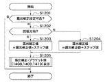
次に、図11のS1102の処理の詳細を、図12のフローチャートに基づいて説明する。 Next, details of the processing of S1102 of FIG. 11 will be described based on the flowchart of FIG.
サブ電子ダイヤル116が操作された場合、システム制御回路50は、露出補正設定可否フラグのセット内容を判別する(S1201)。その結果、露出補正設定可否フラグが「否」の場合は、何ら処理を行うことなく終了する。
When the sub
一方、露出補正設定可否フラグが「可」の場合は、システム制御回路50は、サブ電子ダイヤル116の回転方向を判別する(S1202)。その結果、左回転の場合は、システム制御回路50は、現在の露出補正値から回転操作に応じた露出補正ステップ段数(回転ステップ数)を減じた値を、新しい露出補正値とする(S1203)。
On the other hand, when the exposure correction setting enable / disable flag is “OK”, the
右回転の場合は、システム制御回路50は、現在の露出補正値に操作に応じた露出補正ステップ段数(回転ステップ数)を加えた値を、新しい露出補正値とする(S1204)。
In the case of clockwise rotation, the
次に、システム制御回路50は、図9の露出補正・ブラケット値表示処理を実行することにより、新規な露出補正値に係る指標の位置に、露出補正カーソル1409を移動する(S1205)。この場合、露出補正カーソル1409の移動に連動して、ブラケット設定範囲1407と、露出補正カーソル1409の左右に位置するブラケットカーソル1408,1410も移動することとなる。
Next, the
次に、図11のS1103の処理の詳細を、図13のフローチャートに基づいて説明する。 Next, details of the processing in S1103 of FIG. 11 will be described based on the flowchart of FIG.
メイン電子ダイヤル41が操作された場合、システム制御回路50は、ブラケット設定可否フラグのセット内容を判別する(S1301)。その結果、ブラケット設定可否フラグが「否」の場合は、何ら処理を行うことなく終了する。
When the main electronic dial 41 is operated, the
一方、ブラケット設定可否フラグが「可」の場合は、システム制御回路50は、メイン電子ダイヤル411の回転方向を判別する(S1302)。その結果、左回転の場合は、システム制御回路50は、現在のブラケット値から回転操作に応じたブラケットのステップ段数を減じた値を、新しいブラケット値とする(S1303)。右回転の場合は、システム制御回路50は、現在のブラケット値に操作に応じたブラケットのステップ段数を加えた値を、新しいブラケット値とする(S1304)。
On the other hand, when the bracket setting enable / disable flag is “enabled”, the
次に、システム制御回路50は、図5の目盛り表示処理を実行する(S1305)。この目盛り表示処理は、目盛り1405の範囲を(−4EV〜+4EV)と(−2EV〜+2EV)と間で変更する必要がある可能性があるために実行される。
Next, the
次に、システム制御回路50は、図9の露出補正・ブラケット値表示処理を実行することにより、新規なブラケット値に係る指標の位置に、ブラケットカーソル1408,1410を移動する(S1206)。
Next, the
ここで、露出補正/AEB設定画面の表示バリエーションを、図17A、図17Bに示しておく。なお、、図17A、図17Bでは、グレー色で表示された「+/−」アイコン1401、「AEB」アイコン1402、ガイダンスアイコン1403,1404は、細線で示している。
Here, display variations of the exposure correction / AEB setting screen are shown in FIGS. 17A and 17B. In FIGS. 17A and 17B, the “+/−”
図17A(a)は、露出補正設定、ブラケット設定が共に可能で、露出補正値「0」、ブラケット値「0」、露出補正のステップ段数「1/3」の場合の露出補正/AEB設定画面を示している。 FIG. 17A (a) shows an exposure correction / AEB setting screen when both exposure correction setting and bracket setting are possible, and the exposure correction value is “0”, the bracket value is “0”, and the step number of exposure correction is “1/3”. Is shown.
図17A(b)は、露出補正設定、ブラケット設定が共に可能で、露出補正値「1」、ブラケット値「0」、露出補正のステップ段数「1/3」の場合の露出補正/AEB設定画面を示している。 In FIG. 17A (b), both exposure correction setting and bracket setting are possible, and the exposure correction / AEB setting screen when the exposure correction value is “1”, the bracket value is “0”, and the exposure correction step number is “1/3”. Is shown.
図17A(c)は、露出補正設定、ブラケット設定が共に可能で、露出補正値「0」、ブラケット値「1+1/3」、露出補正のステップ段数「1/3」の場合の露出補正/AEB設定画面を示している。 In FIG. 17A (c), both exposure correction setting and bracket setting are possible, and exposure correction / AEB when the exposure correction value is “0”, the bracket value is “1 + 1/3”, and the step number of exposure correction is “1/3”. The setting screen is shown.
図17A(d)は、露出補正設定、ブラケット設定が共に可能で、露出補正値「1」、ブラケット値「1+1/3」、露出補正のステップ段数「1/3」の場合の露出補正/AEB設定画面を示している。 In FIG. 17A (d), both the exposure correction setting and the bracket setting are possible, and the exposure correction / AEB when the exposure correction value is “1”, the bracket value is “1 + 1/3”, and the step number of the exposure correction is “1/3”. The setting screen is shown.
図17A(e)は、露出補正設定が可能、ブラケット設定が不可能で、露出補正値「0」、露出補正のステップ段数「1/3」の場合の露出補正/AEB設定画面を示している。ブラケット設定が不可能なので、図17A(a)に比べて「AEB」アイコン、メイン電子ダイヤル411を示すガイダンスアイコンをグレーで表示し、設定不可能であることが識別可能な表示形態としている。
FIG. 17A (e) shows an exposure correction / AEB setting screen when exposure correction setting is possible, bracket setting is not possible, exposure correction value is “0”, and exposure correction step number is “1/3”. . Since the bracket setting is impossible, the “AEB” icon and the guidance icon indicating the main
図17A(f)は、露出補正設定が可能、ブラケット設定が不可能で、露出補正値「1」、露出補正のステップ段数「1/3」の場合の露出補正/AEB設定画面を示している。 FIG. 17A (f) shows an exposure correction / AEB setting screen when exposure correction setting is possible, bracket setting is not possible, exposure correction value is “1”, and exposure correction step number is “1/3”. .
図17B(g)は、露出補正設定が不可能、ブラケット設定が可能で、ブラケット値「0」、露出補正のステップ段数「1/3」の場合の露出補正/AEB設定画面を示している。露出補正設定が不可能なので、図17A(a)に比べて露出補正設定可能範囲、「+/−」アイコン、サブ電子ダイヤル411を示すガイダンスアイコンをグレーで表示し、設定不可能であることが識別可能な表示形態としている。
FIG. 17B (g) shows an exposure correction / AEB setting screen when exposure correction cannot be set, bracket setting is possible, the bracket value is “0”, and the step number of exposure correction is “1/3”. Since the exposure correction setting is impossible, the exposure correction setting range, the “+/−” icon, and the guidance icon indicating the sub
図17B(h)は、露出補正設定が不可能、ブラケット設定が可能で、ブラケット値「1+1/3」、露出補正のステップ段数「1/3」の場合の露出補正/AEB設定画面を示している。 FIG. 17B (h) shows an exposure correction / AEB setting screen when exposure correction setting is impossible, bracket setting is possible, bracket value is “1 + 1/3”, and exposure correction step number is “1/3”. Yes.
図17B(i)は、露出補正設定、ブラケット設定が共に不可能の場合の露出補正/AEB設定画面を示している。 FIG. 17B (i) shows an exposure correction / AEB setting screen when neither exposure correction setting nor bracket setting is possible.
本実施の形態により、次のことが分かる。すなわち、露出補正とブラケット設定を加味した状態での露出補正の範囲が目盛り1405により分かる。その露出補正の範囲の中心である適正露出値1414がわかる。
The following can be understood from this embodiment. In other words, the
また、露出補正設定可能範囲1406、ブラケット設定可能範囲1407が、目盛り1405との関係で、すなわち露出補正とブラケット設定を加味した状態で分かる。さらに、露出補正設定可能範囲1406とブラケット設定可能範囲1407との関係も分かる。
Further, an exposure correction setting
ガイダンス用アイコン1401,1402により、それぞれの表示が、露出補正、ブラケット設定に関する表示であることが識別できる。また、ガイダンスアイコン1403,1404により、露出補正、ブラケット設定の設定操作方法が簡単に分かる。
The
なお、上記の実施の形態では、AEB撮影時の撮影コマ数は、露出アンダー側で1枚、露出補正値で1枚、露出オーバー側で1枚の計3枚としていたが、AEB撮影により4コマ以上を撮影する場合にも、上記の実施の形態の技術を適用することが可能である。 In the above embodiment, the number of shot frames at the time of AEB shooting is 3 in total, one on the under-exposure side, one on the exposure correction value, and one on the over-exposure side. The technique of the above-described embodiment can also be applied when shooting more than one frame.
また、上記の実施の形態では、メニューボタン68の操作で露出補正/AEB設定画面を表示していたが、メニューボタン68以外の操作部材の操作により、露出補正/AEB設定画面を表示することも可能である。さらに、露出補正値、ブラケット値は、サブ電子ダイヤル116、メイン電子ダイヤル411以外の操作部材で設定することも可能である。この場合の操作部材としては、例えば、十字キー、マルチコントローラ、更には、タッチ操作可能なアイコン等を用いることができる。タッチ操作可能なアイコンを用いる場合は、そのアイコンの形状をサブ電子ダイヤル116、メイン電子ダイヤル411と同様の形状とするのが好ましい。これにより、ユーザが露出補正値、オートブラケット値を設定する際に、当該アイコンを用いる場合と物理的なサブ電子ダイヤル116、メイン電子ダイヤル411を用いる場合とで、操作部材の混同を可及的に回避できるからである。
In the above-described embodiment, the exposure correction / AEB setting screen is displayed by operating the
また、SETボタン117の操作で、露出補正値、ブラケット値を確定することなく、露出補正値、ブラケット値を変更すると同時に確定することも可能である。また、目盛りの表示間隔、及び指標の表示間隔は、必ずしも等間隔である必要はなく、視認性、操作容易性等を考慮して不等間隔としてもよい。さらに、露出補正/AEB設定画面は、カメラ本体の表示器だけでなく、カメラ本体と接続したPC、無線機器、テレビ等の表示器に表示することも可能である。
Further, by operating the
なお、上述した実施形態では本発明を露出補正と露出ブラケットに適用した例を述べたがこれに限るものではない。測定値に基づいて算出された撮影条件に係る適正設定値を補正する撮影条件補正機能と、補正した撮影条件補正値を含む複数の設定値で複数コマの撮影を自動的に行うオートブラケット機能を利用するための装置であれば本発明を適用可能である。 In the above-described embodiment, the example in which the present invention is applied to the exposure correction and the exposure bracket is described, but the present invention is not limited to this. A shooting condition correction function that corrects the appropriate setting value related to the shooting condition calculated based on the measured value, and an auto bracket function that automatically shoots multiple frames with multiple setting values including the corrected shooting condition correction value if equipment for utilizing the present invention is applicable.
例えば、ストロボ撮影に係る調光補正機能と、調光オートブラケット機能とを利用するための装置に適用可能である。この場合、図14の目盛り1405に、測光に基づいてシステム制御部50が算出した適正光量を基準値1414として、調光補正機能と調光オートブラケット機能を併用した場合に設定可能な全ての光量に係る目盛りを刻めばよい。
For example, it is applicable to equipment for use with exposure compensation function according to the flash photography, the dimming auto bracket function. In this case, all the light quantities that can be set when the dimming correction function and the dimming auto bracket function are used together on the
そして、1406の領域に調光補正設定可能範囲の指標を表示し、1407の領域に調光ブラケットによるブラケット設定可能範囲の指標を表示する。そして、各種アイコン、ガイダンス等は調光補正に関するものを表示すれば良い。同様に、シャッタ速度、絞り値、ホワイトバランス、ISO感度に係るブラケット撮影を利用するための装置にも本発明を適用可能である。
Then, an index of the light control correction settable range is displayed in the
なお、上述した実施の形態の処理は、各機能を具現化したソフトウェアのプログラムコードを記録した記憶媒体をシステム或いは装置に提供してもよい。そして、そのシステム或いは装置のコンピュータ(又はCPUやMPU)が記憶媒体に格納されたプログラムコードを読み出し実行することによって、前述した実施の形態の機能を実現することができる。この場合、記憶媒体から読み出されたプログラムコード自体が前述した実施の形態の機能を実現することになり、そのプログラムコードを記憶した記憶媒体は本発明を構成することになる。 Note that the processing of the above-described embodiment may provide a system or apparatus with a storage medium that records software program codes that embody each function. The functions of the above-described embodiments can be realized by reading and executing the program code stored in the storage medium by the computer (or CPU or MPU) of the system or apparatus. In this case, the program code itself read from the storage medium realizes the functions of the above-described embodiment, and the storage medium storing the program code constitutes the present invention.
このようなプログラムコードを供給するための記憶媒体としては、例えば、フロッピィ(登録商標)ディスク、ハードディスク、光ディスク、光磁気ディスクなどを用いることができる。或いは、CD−ROM、CD−R、磁気テープ、不揮発性のメモリカード、ROMなどを用いることもできる。 As a storage medium for supplying such a program code, for example, a floppy (registered trademark) disk, a hard disk, an optical disk, a magneto-optical disk, or the like can be used. Alternatively, a CD-ROM, CD-R, magnetic tape, nonvolatile memory card, ROM, or the like can be used.
また、コンピュータが読み出したプログラムコードを実行することにより、前述した各実施の形態の機能が実現されるだけではない。そのプログラムコードの指示に基づき、コンピュータ上で稼動しているOS(オペレーティングシステム)などが実際の処理の一部又は全部を行い、その処理によって前述した実施の形態の機能が実現される場合も含まれている。 The functions of the above-described embodiments are not only realized by executing the program code read by the computer. This includes the case where the OS (operating system) running on the computer performs part or all of the actual processing based on the instruction of the program code, and the functions of the above-described embodiments are realized by the processing. It is.
さらに、記憶媒体から読み出されたプログラムコードが、コンピュータに挿入された機能拡張ボードやコンピュータに接続された機能拡張ユニットに備わるメモリに書きこまれてもよい。その後、そのプログラムコードの指示に基づき、その機能拡張ボードや機能拡張ユニットに備わるCPUなどが実際の処理の一部又は全部を行い、その処理によって前述した実施の形態の機能が実現される場合も含むものである。 Further, the program code read from the storage medium may be written in a memory provided in a function expansion board inserted into the computer or a function expansion unit connected to the computer. Thereafter, the CPU of the function expansion board or function expansion unit performs part or all of the actual processing based on the instruction of the program code, and the functions of the above-described embodiments may be realized by the processing. Is included.
50…システム制御回路
56…不揮発性メモリ
417…LCDモニタユニット
1405…目盛り
1406…露出補正設定可能範囲
1407…ブラケット設定可能範囲
1408…アンダー側ブラケットカーソル
1409…露出補正カーソル
1410…オーバー側ブラケットカーソル
50 ...
Claims (14)
オートブラケット撮影におけるブラケット値をユーザからの指示に基づいて設定するブラケット値設定手段と、
前記補正設定手段と前記ブラケット値設定手段とで設定可能な値の範囲を示す目盛りと、前記補正設定手段で設定可能な値の範囲を示し、前記目盛りと対応付けて配列される第1の指標と、前記ブラケット値設定手段で設定可能な値の範囲を示し、前記第1の指標が表示される位置とは異なる位置に前記目盛り及び前記第1の指標と対応付けて配列される第2の指標とを、同一画面上に表示するための処理を行う表示処理手段と、
を有することを特徴とする表示処理装置。 Correction setting means for setting a setting value of a specific shooting setting to a correction value corrected based on an instruction from the user;
Bracket value setting means for setting a bracket value in auto bracket shooting based on an instruction from the user;
A scale indicating a range of values that can be set by the correction setting means and the bracket value setting means, and a first index that indicates a range of values that can be set by the correction setting means and is arranged in association with the scale And a range of values that can be set by the bracket value setting means, and a second range arranged in association with the scale and the first index at a position different from the position where the first index is displayed . Display processing means for performing processing for displaying the indicator on the same screen;
A display processing device comprising:
オートブラケット撮影におけるブラケット値をユーザからの指示に基づいて設定するブラケット値設定ステップと、
前記補正設定ステップと前記ブラケット値設定ステップとで設定可能な値の範囲を示す目盛りと、前記補正設定ステップで設定可能な値の範囲を示し、前記目盛りと対応付けて配列される第1の指標と、前記ブラケット値設定ステップで設定可能な値の範囲を示し、前記第1の指標が表示される位置とは異なる位置に前記目盛り及び前記第1の指標と対応付けて配列される第2の指標とを、同一画面上に表示するための処理を行う表示処理ステップと、
を有することを特徴とする表示処理方法。 A correction setting step for setting a setting value of a specific shooting setting to a correction value corrected based on an instruction from the user;
A bracket value setting step for setting a bracket value in auto bracket shooting based on an instruction from the user;
A scale indicating a range of values that can be set in the correction setting step and the bracket value setting step, and a first index that indicates a range of values that can be set in the correction setting step and is arranged in association with the scale And a range of values that can be set in the bracket value setting step, and a second range arranged in association with the scale and the first index at a position different from the position where the first index is displayed . A display processing step for performing processing for displaying the indicator on the same screen;
A display processing method characterized by comprising:
Priority Applications (4)
| Application Number | Priority Date | Filing Date | Title |
|---|---|---|---|
| JP2008205980A JP5153512B2 (en) | 2008-08-08 | 2008-08-08 | Display processing apparatus, display processing method, program, and storage medium |
| US12/535,582 US8203641B2 (en) | 2008-08-08 | 2009-08-04 | Display processing apparatus and method, and recording medium |
| CN2009101627014A CN101644873B (en) | 2008-08-08 | 2009-08-10 | Display processing apparatus and method |
| US13/473,084 US8421902B2 (en) | 2008-08-08 | 2012-05-16 | Display processing apparatus and method, and recording medium |
Applications Claiming Priority (1)
| Application Number | Priority Date | Filing Date | Title |
|---|---|---|---|
| JP2008205980A JP5153512B2 (en) | 2008-08-08 | 2008-08-08 | Display processing apparatus, display processing method, program, and storage medium |
Publications (3)
| Publication Number | Publication Date |
|---|---|
| JP2010045425A JP2010045425A (en) | 2010-02-25 |
| JP2010045425A5 JP2010045425A5 (en) | 2011-02-03 |
| JP5153512B2 true JP5153512B2 (en) | 2013-02-27 |
Family
ID=41652567
Family Applications (1)
| Application Number | Title | Priority Date | Filing Date |
|---|---|---|---|
| JP2008205980A Active JP5153512B2 (en) | 2008-08-08 | 2008-08-08 | Display processing apparatus, display processing method, program, and storage medium |
Country Status (3)
| Country | Link |
|---|---|
| US (2) | US8203641B2 (en) |
| JP (1) | JP5153512B2 (en) |
| CN (1) | CN101644873B (en) |
Cited By (1)
| Publication number | Priority date | Publication date | Assignee | Title |
|---|---|---|---|---|
| US10440257B2 (en) | 2015-02-04 | 2019-10-08 | Canon Kabushiki Kaisha | Electronic device, imaging control apparatus and control method thereof |
Families Citing this family (24)
| Publication number | Priority date | Publication date | Assignee | Title |
|---|---|---|---|---|
| JP5153512B2 (en) * | 2008-08-08 | 2013-02-27 | キヤノン株式会社 | Display processing apparatus, display processing method, program, and storage medium |
| JP5495878B2 (en) * | 2010-03-24 | 2014-05-21 | キヤノン株式会社 | Imaging apparatus, control method thereof, and program |
| JP5693355B2 (en) * | 2011-04-27 | 2015-04-01 | キヤノン株式会社 | Imaging apparatus, control method therefor, program, and storage medium |
| JP5854848B2 (en) * | 2012-01-10 | 2016-02-09 | キヤノン株式会社 | IMAGING DEVICE, IMAGING DEVICE CONTROL METHOD, PROGRAM, AND STORAGE MEDIUM |
| JP5804451B2 (en) * | 2014-08-18 | 2015-11-04 | リコーイメージング株式会社 | Digital camera, digital camera photographing method and program |
| JP6571941B2 (en) * | 2015-02-04 | 2019-09-04 | キヤノン株式会社 | Electronic device and control method thereof |
| US9854156B1 (en) | 2016-06-12 | 2017-12-26 | Apple Inc. | User interface for camera effects |
| WO2018085426A1 (en) | 2016-11-01 | 2018-05-11 | Snap Inc. | Systems and methods for fast video capture and sensor adjustment |
| US10291858B2 (en) * | 2017-04-14 | 2019-05-14 | Panasonic Intellectual Property Management Co., Ltd. | Imaging apparatus including two operation parts for determining a set value |
| DK180859B1 (en) | 2017-06-04 | 2022-05-23 | Apple Inc | USER INTERFACE CAMERA EFFECTS |
| EP3454545A1 (en) | 2017-09-04 | 2019-03-13 | Canon Kabushiki Kaisha | Image capturing control apparatus and control method |
| US11112964B2 (en) | 2018-02-09 | 2021-09-07 | Apple Inc. | Media capture lock affordance for graphical user interface |
| US10375313B1 (en) | 2018-05-07 | 2019-08-06 | Apple Inc. | Creative camera |
| US11722764B2 (en) | 2018-05-07 | 2023-08-08 | Apple Inc. | Creative camera |
| DK201870623A1 (en) | 2018-09-11 | 2020-04-15 | Apple Inc. | User interfaces for simulated depth effects |
| US10674072B1 (en) | 2019-05-06 | 2020-06-02 | Apple Inc. | User interfaces for capturing and managing visual media |
| US11770601B2 (en) | 2019-05-06 | 2023-09-26 | Apple Inc. | User interfaces for capturing and managing visual media |
| US11128792B2 (en) | 2018-09-28 | 2021-09-21 | Apple Inc. | Capturing and displaying images with multiple focal planes |
| US11321857B2 (en) | 2018-09-28 | 2022-05-03 | Apple Inc. | Displaying and editing images with depth information |
| US11706521B2 (en) | 2019-05-06 | 2023-07-18 | Apple Inc. | User interfaces for capturing and managing visual media |
| US11039074B1 (en) | 2020-06-01 | 2021-06-15 | Apple Inc. | User interfaces for managing media |
| US11212449B1 (en) | 2020-09-25 | 2021-12-28 | Apple Inc. | User interfaces for media capture and management |
| US11778339B2 (en) | 2021-04-30 | 2023-10-03 | Apple Inc. | User interfaces for altering visual media |
| US11539876B2 (en) | 2021-04-30 | 2022-12-27 | Apple Inc. | User interfaces for altering visual media |
Family Cites Families (19)
| Publication number | Priority date | Publication date | Assignee | Title |
|---|---|---|---|---|
| JPH028828A (en) * | 1988-06-28 | 1990-01-12 | Canon Inc | Camera with auto bracket function |
| US4974012A (en) * | 1988-06-28 | 1990-11-27 | Canon Kabushiki Kaisha | Display device for automatic exposure bracketing shooting |
| JP2646491B2 (en) * | 1988-06-28 | 1997-08-27 | キヤノン株式会社 | Information display device for camera |
| DE69116395T2 (en) * | 1990-03-01 | 1996-07-04 | Minolta Camera Kk | Camera with learning function |
| US5463443A (en) * | 1992-03-06 | 1995-10-31 | Nikon Corporation | Camera for preventing camera shake |
| GB2272068B (en) * | 1992-10-20 | 1996-07-31 | Asahi Optical Co Ltd | Camera with learning function |
| JPH0876187A (en) * | 1994-09-07 | 1996-03-22 | Nikon Corp | Photometry device for camera |
| JPH1115051A (en) * | 1997-06-23 | 1999-01-22 | Canon Inc | Flashing device, camera and camera system |
| JP4018368B2 (en) * | 2001-10-30 | 2007-12-05 | キヤノン株式会社 | IMAGING DEVICE AND OPERATION CONTROL SYSTEM FOR IMAGING DEVICE |
| US7286177B2 (en) * | 2001-12-19 | 2007-10-23 | Nokia Corporation | Digital camera |
| JP4250436B2 (en) * | 2003-02-27 | 2009-04-08 | キヤノン株式会社 | Display control device |
| JP4434624B2 (en) * | 2003-05-12 | 2010-03-17 | キヤノン株式会社 | Imaging apparatus, imaging method, computer program, and computer-readable storage medium |
| JP2005257743A (en) * | 2004-03-09 | 2005-09-22 | Canon Inc | Electronic camera having auto bracketing function |
| JP4293089B2 (en) * | 2004-08-05 | 2009-07-08 | ソニー株式会社 | Imaging apparatus, imaging control method, and program |
| JP2007142884A (en) * | 2005-11-18 | 2007-06-07 | Canon Inc | Image sensing device and its control method |
| JP4971718B2 (en) * | 2006-08-11 | 2012-07-11 | キヤノン株式会社 | Imaging device |
| JP5031342B2 (en) * | 2006-12-01 | 2012-09-19 | キヤノン株式会社 | Imaging apparatus and control method thereof |
| JP4404128B2 (en) * | 2007-10-09 | 2010-01-27 | 株式会社ニコン | Electronic camera |
| JP5153512B2 (en) * | 2008-08-08 | 2013-02-27 | キヤノン株式会社 | Display processing apparatus, display processing method, program, and storage medium |
-
2008
- 2008-08-08 JP JP2008205980A patent/JP5153512B2/en active Active
-
2009
- 2009-08-04 US US12/535,582 patent/US8203641B2/en not_active Expired - Fee Related
- 2009-08-10 CN CN2009101627014A patent/CN101644873B/en not_active Expired - Fee Related
-
2012
- 2012-05-16 US US13/473,084 patent/US8421902B2/en not_active Expired - Fee Related
Cited By (1)
| Publication number | Priority date | Publication date | Assignee | Title |
|---|---|---|---|---|
| US10440257B2 (en) | 2015-02-04 | 2019-10-08 | Canon Kabushiki Kaisha | Electronic device, imaging control apparatus and control method thereof |
Also Published As
| Publication number | Publication date |
|---|---|
| US20100033615A1 (en) | 2010-02-11 |
| JP2010045425A (en) | 2010-02-25 |
| US8421902B2 (en) | 2013-04-16 |
| CN101644873A (en) | 2010-02-10 |
| CN101644873B (en) | 2012-07-04 |
| US20120224092A1 (en) | 2012-09-06 |
| US8203641B2 (en) | 2012-06-19 |
Similar Documents
| Publication | Publication Date | Title |
|---|---|---|
| JP5153512B2 (en) | Display processing apparatus, display processing method, program, and storage medium | |
| JP5854848B2 (en) | IMAGING DEVICE, IMAGING DEVICE CONTROL METHOD, PROGRAM, AND STORAGE MEDIUM | |
| JP5693355B2 (en) | Imaging apparatus, control method therefor, program, and storage medium | |
| JP4991621B2 (en) | Imaging device | |
| KR20150019710A (en) | Photographing apparatus and method | |
| JP2007201693A (en) | Camera and camera control method | |
| JP2001309210A (en) | Digital camera | |
| JP5486628B2 (en) | Imaging device | |
| JP4284440B2 (en) | Electronic camera | |
| JP6009056B2 (en) | IMAGING DEVICE, IMAGING DEVICE CONTROL METHOD, ELECTRONIC DEVICE, ELECTRONIC DEVICE CONTROL METHOD, PROGRAM, STORAGE MEDIUM | |
| JP2012029055A (en) | Imaging device, control method of the same, program, and storage medium | |
| JP2004274135A (en) | Electronic camera | |
| JP5615086B2 (en) | Imaging apparatus, control method thereof, and program | |
| JP7084769B2 (en) | Electronic devices, control methods, programs, and storage media for electronic devices | |
| JP2014048382A (en) | Display control device, control method, program, and storage medium | |
| JP5207930B2 (en) | IMAGING DEVICE, IMAGING DEVICE CONTROL METHOD, PROGRAM, AND RECORDING MEDIUM | |
| JP2005221578A (en) | Imaging apparatus, control method thereof, program and storage medium | |
| JP7134730B2 (en) | Imaging device and its control method | |
| JP6360397B2 (en) | Imaging apparatus, control method therefor, program, and storage medium | |
| JP2024018591A (en) | Imaging device, focus adjustment support method, program and storage medium | |
| JP2021069005A (en) | Imaging control device, imaging device, control method, program, and recording medium | |
| JP2021068969A (en) | Imaging apparatus, control method of imaging apparatus, and program thereof | |
| JP2020010316A (en) | Imaging apparatus, control method of the same, and program | |
| JP2010206755A (en) | Imaging device | |
| JP2008035389A (en) | Imaging apparatus, control method and program |
Legal Events
| Date | Code | Title | Description |
|---|---|---|---|
| A521 | Request for written amendment filed |
Free format text: JAPANESE INTERMEDIATE CODE: A523 Effective date: 20101213 |
|
| A621 | Written request for application examination |
Free format text: JAPANESE INTERMEDIATE CODE: A621 Effective date: 20101213 |
|
| A977 | Report on retrieval |
Free format text: JAPANESE INTERMEDIATE CODE: A971007 Effective date: 20120215 |
|
| A131 | Notification of reasons for refusal |
Free format text: JAPANESE INTERMEDIATE CODE: A131 Effective date: 20120221 |
|
| A521 | Request for written amendment filed |
Free format text: JAPANESE INTERMEDIATE CODE: A523 Effective date: 20120420 |
|
| TRDD | Decision of grant or rejection written | ||
| A01 | Written decision to grant a patent or to grant a registration (utility model) |
Free format text: JAPANESE INTERMEDIATE CODE: A01 Effective date: 20121106 |
|
| A61 | First payment of annual fees (during grant procedure) |
Free format text: JAPANESE INTERMEDIATE CODE: A61 Effective date: 20121204 |
|
| FPAY | Renewal fee payment (event date is renewal date of database) |
Free format text: PAYMENT UNTIL: 20151214 Year of fee payment: 3 |
|
| R151 | Written notification of patent or utility model registration |
Ref document number: 5153512 Country of ref document: JP Free format text: JAPANESE INTERMEDIATE CODE: R151 |
|
| FPAY | Renewal fee payment (event date is renewal date of database) |
Free format text: PAYMENT UNTIL: 20151214 Year of fee payment: 3 |