JP5145674B2 - Refrigeration equipment - Google Patents
Refrigeration equipment Download PDFInfo
- Publication number
- JP5145674B2 JP5145674B2 JP2006246151A JP2006246151A JP5145674B2 JP 5145674 B2 JP5145674 B2 JP 5145674B2 JP 2006246151 A JP2006246151 A JP 2006246151A JP 2006246151 A JP2006246151 A JP 2006246151A JP 5145674 B2 JP5145674 B2 JP 5145674B2
- Authority
- JP
- Japan
- Prior art keywords
- refrigerant
- expansion mechanism
- heat exchanger
- pressure
- state
- Prior art date
- Legal status (The legal status is an assumption and is not a legal conclusion. Google has not performed a legal analysis and makes no representation as to the accuracy of the status listed.)
- Active
Links
Images


Classifications
-
- F—MECHANICAL ENGINEERING; LIGHTING; HEATING; WEAPONS; BLASTING
- F25—REFRIGERATION OR COOLING; COMBINED HEATING AND REFRIGERATION SYSTEMS; HEAT PUMP SYSTEMS; MANUFACTURE OR STORAGE OF ICE; LIQUEFACTION SOLIDIFICATION OF GASES
- F25B—REFRIGERATION MACHINES, PLANTS OR SYSTEMS; COMBINED HEATING AND REFRIGERATION SYSTEMS; HEAT PUMP SYSTEMS
- F25B9/00—Compression machines, plants or systems, in which the refrigerant is air or other gas of low boiling point
- F25B9/002—Compression machines, plants or systems, in which the refrigerant is air or other gas of low boiling point characterised by the refrigerant
- F25B9/008—Compression machines, plants or systems, in which the refrigerant is air or other gas of low boiling point characterised by the refrigerant the refrigerant being carbon dioxide
-
- F—MECHANICAL ENGINEERING; LIGHTING; HEATING; WEAPONS; BLASTING
- F25—REFRIGERATION OR COOLING; COMBINED HEATING AND REFRIGERATION SYSTEMS; HEAT PUMP SYSTEMS; MANUFACTURE OR STORAGE OF ICE; LIQUEFACTION SOLIDIFICATION OF GASES
- F25B—REFRIGERATION MACHINES, PLANTS OR SYSTEMS; COMBINED HEATING AND REFRIGERATION SYSTEMS; HEAT PUMP SYSTEMS
- F25B41/00—Fluid-circulation arrangements
- F25B41/30—Expansion means; Dispositions thereof
- F25B41/39—Dispositions with two or more expansion means arranged in series, i.e. multi-stage expansion, on a refrigerant line leading to the same evaporator
-
- F—MECHANICAL ENGINEERING; LIGHTING; HEATING; WEAPONS; BLASTING
- F25—REFRIGERATION OR COOLING; COMBINED HEATING AND REFRIGERATION SYSTEMS; HEAT PUMP SYSTEMS; MANUFACTURE OR STORAGE OF ICE; LIQUEFACTION SOLIDIFICATION OF GASES
- F25B—REFRIGERATION MACHINES, PLANTS OR SYSTEMS; COMBINED HEATING AND REFRIGERATION SYSTEMS; HEAT PUMP SYSTEMS
- F25B13/00—Compression machines, plants or systems, with reversible cycle
-
- F—MECHANICAL ENGINEERING; LIGHTING; HEATING; WEAPONS; BLASTING
- F25—REFRIGERATION OR COOLING; COMBINED HEATING AND REFRIGERATION SYSTEMS; HEAT PUMP SYSTEMS; MANUFACTURE OR STORAGE OF ICE; LIQUEFACTION SOLIDIFICATION OF GASES
- F25B—REFRIGERATION MACHINES, PLANTS OR SYSTEMS; COMBINED HEATING AND REFRIGERATION SYSTEMS; HEAT PUMP SYSTEMS
- F25B2309/00—Gas cycle refrigeration machines
- F25B2309/06—Compression machines, plants or systems characterised by the refrigerant being carbon dioxide
- F25B2309/061—Compression machines, plants or systems characterised by the refrigerant being carbon dioxide with cycle highest pressure above the supercritical pressure
-
- F—MECHANICAL ENGINEERING; LIGHTING; HEATING; WEAPONS; BLASTING
- F25—REFRIGERATION OR COOLING; COMBINED HEATING AND REFRIGERATION SYSTEMS; HEAT PUMP SYSTEMS; MANUFACTURE OR STORAGE OF ICE; LIQUEFACTION SOLIDIFICATION OF GASES
- F25B—REFRIGERATION MACHINES, PLANTS OR SYSTEMS; COMBINED HEATING AND REFRIGERATION SYSTEMS; HEAT PUMP SYSTEMS
- F25B2400/00—General features or devices for refrigeration machines, plants or systems, combined heating and refrigeration systems or heat-pump systems, i.e. not limited to a particular subgroup of F25B
- F25B2400/16—Receivers
-
- F—MECHANICAL ENGINEERING; LIGHTING; HEATING; WEAPONS; BLASTING
- F25—REFRIGERATION OR COOLING; COMBINED HEATING AND REFRIGERATION SYSTEMS; HEAT PUMP SYSTEMS; MANUFACTURE OR STORAGE OF ICE; LIQUEFACTION SOLIDIFICATION OF GASES
- F25B—REFRIGERATION MACHINES, PLANTS OR SYSTEMS; COMBINED HEATING AND REFRIGERATION SYSTEMS; HEAT PUMP SYSTEMS
- F25B2600/00—Control issues
- F25B2600/17—Control issues by controlling the pressure of the condenser
-
- F—MECHANICAL ENGINEERING; LIGHTING; HEATING; WEAPONS; BLASTING
- F25—REFRIGERATION OR COOLING; COMBINED HEATING AND REFRIGERATION SYSTEMS; HEAT PUMP SYSTEMS; MANUFACTURE OR STORAGE OF ICE; LIQUEFACTION SOLIDIFICATION OF GASES
- F25B—REFRIGERATION MACHINES, PLANTS OR SYSTEMS; COMBINED HEATING AND REFRIGERATION SYSTEMS; HEAT PUMP SYSTEMS
- F25B2600/00—Control issues
- F25B2600/25—Control of valves
- F25B2600/2513—Expansion valves
-
- F—MECHANICAL ENGINEERING; LIGHTING; HEATING; WEAPONS; BLASTING
- F25—REFRIGERATION OR COOLING; COMBINED HEATING AND REFRIGERATION SYSTEMS; HEAT PUMP SYSTEMS; MANUFACTURE OR STORAGE OF ICE; LIQUEFACTION SOLIDIFICATION OF GASES
- F25B—REFRIGERATION MACHINES, PLANTS OR SYSTEMS; COMBINED HEATING AND REFRIGERATION SYSTEMS; HEAT PUMP SYSTEMS
- F25B2700/00—Sensing or detecting of parameters; Sensors therefor
- F25B2700/19—Pressures
- F25B2700/191—Pressures near an expansion valve
-
- F—MECHANICAL ENGINEERING; LIGHTING; HEATING; WEAPONS; BLASTING
- F25—REFRIGERATION OR COOLING; COMBINED HEATING AND REFRIGERATION SYSTEMS; HEAT PUMP SYSTEMS; MANUFACTURE OR STORAGE OF ICE; LIQUEFACTION SOLIDIFICATION OF GASES
- F25B—REFRIGERATION MACHINES, PLANTS OR SYSTEMS; COMBINED HEATING AND REFRIGERATION SYSTEMS; HEAT PUMP SYSTEMS
- F25B2700/00—Sensing or detecting of parameters; Sensors therefor
- F25B2700/21—Temperatures
- F25B2700/2102—Temperatures at the outlet of the gas cooler
-
- F—MECHANICAL ENGINEERING; LIGHTING; HEATING; WEAPONS; BLASTING
- F25—REFRIGERATION OR COOLING; COMBINED HEATING AND REFRIGERATION SYSTEMS; HEAT PUMP SYSTEMS; MANUFACTURE OR STORAGE OF ICE; LIQUEFACTION SOLIDIFICATION OF GASES
- F25B—REFRIGERATION MACHINES, PLANTS OR SYSTEMS; COMBINED HEATING AND REFRIGERATION SYSTEMS; HEAT PUMP SYSTEMS
- F25B40/00—Subcoolers, desuperheaters or superheaters
- F25B40/02—Subcoolers
-
- F—MECHANICAL ENGINEERING; LIGHTING; HEATING; WEAPONS; BLASTING
- F25—REFRIGERATION OR COOLING; COMBINED HEATING AND REFRIGERATION SYSTEMS; HEAT PUMP SYSTEMS; MANUFACTURE OR STORAGE OF ICE; LIQUEFACTION SOLIDIFICATION OF GASES
- F25B—REFRIGERATION MACHINES, PLANTS OR SYSTEMS; COMBINED HEATING AND REFRIGERATION SYSTEMS; HEAT PUMP SYSTEMS
- F25B5/00—Compression machines, plants or systems, with several evaporator circuits, e.g. for varying refrigerating capacity
- F25B5/02—Compression machines, plants or systems, with several evaporator circuits, e.g. for varying refrigerating capacity arranged in parallel
-
- F—MECHANICAL ENGINEERING; LIGHTING; HEATING; WEAPONS; BLASTING
- F25—REFRIGERATION OR COOLING; COMBINED HEATING AND REFRIGERATION SYSTEMS; HEAT PUMP SYSTEMS; MANUFACTURE OR STORAGE OF ICE; LIQUEFACTION SOLIDIFICATION OF GASES
- F25B—REFRIGERATION MACHINES, PLANTS OR SYSTEMS; COMBINED HEATING AND REFRIGERATION SYSTEMS; HEAT PUMP SYSTEMS
- F25B7/00—Compression machines, plants or systems, with cascade operation, i.e. with two or more circuits, the heat from the condenser of one circuit being absorbed by the evaporator of the next circuit
Landscapes
- Engineering & Computer Science (AREA)
- Physics & Mathematics (AREA)
- Mechanical Engineering (AREA)
- Thermal Sciences (AREA)
- General Engineering & Computer Science (AREA)
- Chemical & Material Sciences (AREA)
- Chemical Kinetics & Catalysis (AREA)
- Air Conditioning Control Device (AREA)
Description
本発明は、冷凍装置、特に冷凍サイクル中に冷媒が超臨界状態となる冷凍装置に関する。 The present invention relates to a refrigeration apparatus, and more particularly to a refrigeration apparatus in which a refrigerant enters a supercritical state during a refrigeration cycle.
従来、圧縮機、放熱器、過冷却器、第1膨張弁、受液器、第2膨張弁、および蒸発器を順次接続した冷媒回路を備える冷凍装置が公に知られている(例えば、特許文献1参照)。
ところで、このような冷凍装置の冷媒回路において、第1膨張弁によって冷媒が飽和線近傍の状態まで膨張されると、設置環境によっては(例えば、夏季で過負荷となった場合など)その冷媒が臨界点近傍の状態となってしまう場合がある。このように冷媒が臨界点近傍の状態となってしまうと、キャビテーションが生じ上記構成部品に悪影響を及ぼすおそれがあるだけでなく、受液器における冷媒の液面制御が困難になり、冷媒回路内の冷媒を適切な量に保つことができなくなるおそれがある。 By the way, in such a refrigerant circuit of the refrigeration apparatus, when the refrigerant is expanded to a state near the saturation line by the first expansion valve, depending on the installation environment (for example, in the case of an overload in the summer season) In some cases, the critical point may be reached. If the refrigerant is in the vicinity of the critical point as described above, cavitation may occur and the above components may be adversely affected, and it becomes difficult to control the liquid level of the refrigerant in the liquid receiver. There is a risk that it will not be possible to maintain an appropriate amount of the refrigerant.
本発明の課題は、上記のような冷媒装置において第1膨張弁等によって冷媒が飽和線近傍の状態まで膨張される場合に冷媒が臨界点近傍の状態となることを回避することにある。 An object of the present invention is to avoid the refrigerant from being in the vicinity of the critical point when the refrigerant is expanded to a state near the saturation line by the first expansion valve or the like in the refrigerant device as described above.
第1発明に係る冷凍装置は、圧縮機構、放熱器、第1膨張機構、冷媒冷却部、受液器、第2膨張機構、蒸発器、高圧圧力センサ、温度センサ、中間圧圧力センサおよび制御部を備える。圧縮機構は、冷媒を圧縮する。放熱器は、圧縮機構の冷媒吐出側に接続される。第1膨張機構は、放熱器の出口側に接続される。冷媒冷却部は、放熱器の出口側と第1膨張機構の冷媒流入側との間に配置される。受液器は、第1膨張機構の冷媒流出側に接続される。第2膨張機構は、受液器の出口側に接続される。蒸発器は、第2膨張機構の冷媒流出側に接続されると共に圧縮機構の冷媒吸入側に接続される。高圧圧力センサは圧縮機の吐出側に設けられている。温度センサは放熱器の低温側に設けられている。中間圧圧力センサは、第1膨張機構と受液器との間に設けられている。制御部は、温度センサの温度情報および前記中間圧圧力センサの圧力情報に基づいて前記第1膨張機構から流出した冷媒が臨界点近傍の状態になると判断した場合、通常制御から冷媒冷却制御へと切り換える制御切換手段を有している。第1膨張機構から流出した冷媒の状態が飽和線近傍の状態になり且つ臨界点近傍の状態にならないように冷媒冷却部により冷媒を冷却する冷媒冷却制御を行う。具体的には、通常制御ではCOPが向上するように、前記第1膨張機構および前記第2膨張機構の開度が制御される。また、冷媒冷却制御では、前記第1膨張機構および前記第2膨張機構の開度及び/または前記冷媒冷却部を制御して、中間圧圧力センサが示す圧力が{臨界圧力(MPa)−0.3(MPa)}の圧力以下となるようにし、第1膨張機構から流出した冷媒の状態が飽和線上の状態になり且つ臨界点近傍の状態にならないように、第1膨張機構および第2膨張機構の開度が制御され、受液器内の冷媒の状態を飽和状態に維持できるように制御する。 The refrigeration apparatus according to the first invention includes a compression mechanism, a radiator, a first expansion mechanism, a refrigerant cooling unit, a liquid receiver, a second expansion mechanism, an evaporator, a high pressure sensor, a temperature sensor, an intermediate pressure sensor, and a control unit. Is provided. The compression mechanism compresses the refrigerant. The radiator is connected to the refrigerant discharge side of the compression mechanism. The first expansion mechanism is connected to the outlet side of the radiator. The refrigerant cooling unit is disposed between the outlet side of the radiator and the refrigerant inflow side of the first expansion mechanism. The liquid receiver is connected to the refrigerant outflow side of the first expansion mechanism. The second expansion mechanism is connected to the outlet side of the liquid receiver. The evaporator is connected to the refrigerant outflow side of the second expansion mechanism and to the refrigerant suction side of the compression mechanism. The high pressure sensor is provided on the discharge side of the compressor. The temperature sensor is provided on the low temperature side of the radiator. The intermediate pressure sensor is provided between the first expansion mechanism and the liquid receiver. When the control unit determines that the refrigerant flowing out of the first expansion mechanism is in a state near the critical point based on the temperature information of the temperature sensor and the pressure information of the intermediate pressure sensor, the control unit shifts from the normal control to the refrigerant cooling control. Control switching means for switching is provided. Refrigerant cooling control is performed to cool the refrigerant by the refrigerant cooling unit so that the state of the refrigerant flowing out of the first expansion mechanism becomes a state near the saturation line and does not become a state near the critical point. Specifically, the opening degrees of the first expansion mechanism and the second expansion mechanism are controlled so that COP is improved in normal control. Further, in the refrigerant cooling control, the opening degree of the first expansion mechanism and the second expansion mechanism and / or the refrigerant cooling unit is controlled, and the pressure indicated by the intermediate pressure sensor becomes {critical pressure (MPa) -0. 3 (MPa)} or less so that the state of the refrigerant flowing out of the first expansion mechanism becomes a state on the saturation line and does not become a state near the critical point. Is controlled so that the state of the refrigerant in the liquid receiver can be maintained in a saturated state.
この冷凍装置では、中間圧圧力センサの圧力情報に基づいて記第1膨張機構から流出した冷媒が臨界点近傍の状態になると判断した場合、制御切換手段により、冷媒冷却制御と通常制御とを切り換える。このため、この冷凍装置では、通常制御ではCOPを考慮した制御を実行することが可能となる。また、この冷凍装置では、冷媒冷却制御において、前記第1膨張機構および前記第2膨張機構の開度及び/または前記冷媒冷却部を制御して、第1膨張機構から流出した冷媒が飽和線近傍の状態になり且つ冷媒の圧力が{臨界圧力(MPa)−0.3(MPa)}の圧力以下となるように冷媒冷却部により冷媒が冷却される。このため、この冷凍装置では、第1膨張機構によって冷媒が飽和線近傍の状態まで膨張される場合に冷媒が臨界点近傍の状態となることを回避することができる。 In this refrigeration apparatus, when it is determined that the refrigerant flowing out of the first expansion mechanism is in the vicinity of the critical point based on the pressure information of the intermediate pressure sensor , the control switching means switches between the refrigerant cooling control and the normal control. . For this reason, in this refrigeration apparatus, it is possible to execute control in consideration of COP in normal control. Further, in this refrigeration apparatus, in refrigerant cooling control, the degree of opening of the first expansion mechanism and the second expansion mechanism and / or the refrigerant cooling unit is controlled so that the refrigerant flowing out of the first expansion mechanism is near the saturation line. Then, the refrigerant is cooled by the refrigerant cooling unit so that the refrigerant pressure becomes equal to or lower than the pressure of {critical pressure (MPa) -0.3 (MPa)}. For this reason, in this refrigeration apparatus, when the refrigerant is expanded to the state near the saturation line by the first expansion mechanism, the refrigerant can be prevented from being in the state near the critical point.
第2発明に係る冷凍装置は、第1発明に係る冷凍装置であって、冷媒冷却部は、放熱器の出口側と第1膨張機構の流入側とを接続する第1冷媒配管に流れる冷媒と、蒸発器の出口側と圧縮機構の冷媒吸入側とを接続する第2冷媒配管に流れる冷媒との間で熱交換を行わせる内部熱交換器である。そして、冷媒冷却制御では、第1膨張機構から流出した冷媒の状態が飽和線近傍の状態になり且つ臨界点近傍の状態にならないように第1膨張機構と第2膨張機構とが制御される。 A refrigeration apparatus according to a second aspect of the present invention is the refrigeration apparatus according to the first aspect of the present invention, wherein the refrigerant cooling part is a refrigerant flowing through a first refrigerant pipe connecting the outlet side of the radiator and the inflow side of the first expansion mechanism. An internal heat exchanger that exchanges heat between the refrigerant flowing in the second refrigerant pipe that connects the outlet side of the evaporator and the refrigerant suction side of the compression mechanism. In the refrigerant cooling control, the first expansion mechanism and the second expansion mechanism are controlled so that the state of the refrigerant flowing out from the first expansion mechanism becomes a state near the saturation line and does not become a state near the critical point.
この冷凍装置では、冷媒冷却部が内部熱交換器である。そして、冷媒冷却制御において、第1膨張機構から流出した冷媒の状態が飽和線近傍の状態になり且つ臨界点近傍の状態にならないように第1膨張機構と第2膨張機構とが制御される。このため、この冷凍装置では、第1膨張機構によって冷媒が飽和線近傍の状態まで膨張される場合に冷媒が臨界点近傍の状態となることを回避することができる。また、チラー等の外部冷却装置を必要としないため製造コストを低く抑えることができる。 In this refrigeration apparatus, the refrigerant cooling unit is an internal heat exchanger. In the refrigerant cooling control, the first expansion mechanism and the second expansion mechanism are controlled so that the state of the refrigerant flowing out from the first expansion mechanism becomes a state near the saturation line and does not become a state near the critical point. For this reason, in this refrigeration apparatus, when the refrigerant is expanded to the state near the saturation line by the first expansion mechanism, the refrigerant can be prevented from being in the state near the critical point. Further, since an external cooling device such as a chiller is not required, the manufacturing cost can be kept low.
第3発明に係る冷凍装置は、第2発明に係る冷凍装置であって、温度検知部をさらに備える。温度検知部は、放熱器の出口近傍または第1膨張機構の冷媒流入口近傍に設けられる。そして、冷媒冷却制御では、温度検知部によって検知される温度が所定の温度以上である場合に、第1膨張機構から流出した冷媒が飽和線近傍の状態になり且つ冷媒の圧力が{臨界圧力(MPa)−0.3(MPa)}の圧力以下となるように冷媒冷却部により冷媒が冷却される。 A refrigeration apparatus according to a third aspect of the present invention is the refrigeration apparatus according to the second aspect of the present invention, further comprising a temperature detection unit. The temperature detector is provided near the outlet of the radiator or near the refrigerant inlet of the first expansion mechanism. In the refrigerant cooling control, when the temperature detected by the temperature detection unit is equal to or higher than a predetermined temperature, the refrigerant flowing out of the first expansion mechanism is in a state near the saturation line and the refrigerant pressure is {critical pressure ( The refrigerant is cooled by the refrigerant cooling unit so as to be equal to or lower than the pressure of (MPa) −0.3 (MPa)}.
この冷凍装置では、冷媒冷却制御において、温度検知部によって検知される温度が所定の温度以上である場合に、第1膨張機構から流出した冷媒が飽和線近傍の状態になり且つ冷媒の圧力が{臨界圧力(MPa)−0.3(MPa)}の圧力以下となるように冷媒冷却部により冷媒が冷却される。このため、この冷凍装置では、第1膨張機構によって冷媒が飽和線近傍の状態まで膨張される場合であって冷媒が臨界点近傍の状態となるおそれのある場合に冷媒が臨界点近傍の状態となることを回避することができる。 In this refrigeration apparatus, in the refrigerant cooling control, when the temperature detected by the temperature detection unit is equal to or higher than a predetermined temperature, the refrigerant flowing out from the first expansion mechanism is in the vicinity of the saturation line and the pressure of the refrigerant is { The refrigerant is cooled by the refrigerant cooling unit so as to be equal to or lower than the pressure of critical pressure (MPa) −0.3 (MPa)}. For this reason, in this refrigeration apparatus, when the refrigerant is expanded to a state near the saturation line by the first expansion mechanism and the refrigerant may be in a state near the critical point, the refrigerant is in a state near the critical point. Can be avoided.
本発明に係る冷凍装置では、通常制御ではCOPを考慮した制御を実行し、冷媒冷却制御では、第1膨張機構によって冷媒が飽和線近傍の状態まで膨張される場合に冷媒が臨界点近傍の状態となることを回避することができる。 In the refrigeration apparatus according to the present invention, the control in consideration of the COP is executed in the normal control, and in the refrigerant cooling control, the refrigerant is in the vicinity of the critical point when the refrigerant is expanded to the state near the saturation line by the first expansion mechanism. Can be avoided.
<空気調和装置の構成>
本発明の実施の形態に係る空気調和装置1の概略冷媒回路2を図1に示す。
<Configuration of air conditioner>
A
この空気調和装置1は、二酸化炭素を冷媒として冷房運転および暖房運転が可能な空気調和装置であって、主に冷媒回路2、送風ファン26,32、制御装置23、高圧圧力センサ21、温度センサ22、および中間圧圧力センサ24等から構成されている。
The air conditioner 1 is an air conditioner that can perform cooling and heating operations using carbon dioxide as a refrigerant. The air conditioner 1 mainly includes a
冷媒回路2には主に、圧縮機11、四路切換弁12、室外熱交換器13、内部熱交換器14、第1電動膨張弁15、受液器16、第2電動膨張弁17、および室内熱交換器31が配備されており、各装置は、図1に示されるように、冷媒配管を介して接続されている。
The
そして、本実施の形態において、空気調和装置1は、分離型の空気調和装置であって、室内熱交換器31および室内ファン32を主に有する室内ユニット30と、圧縮機11、四路切換弁12、室外熱交換器13、内部熱交換器14、第1電動膨張弁15、受液器16、第2電動膨張弁17、高圧圧力センサ21、温度センサ22、および制御装置23を主に有する室外ユニット10と、室内ユニット30の冷媒液等配管と室外ユニット10の冷媒液等配管とを接続する第1連絡配管41と、室内ユニット30の冷媒ガス等配管と室外ユニット10の冷媒ガス等配管とを接続する第2連絡配管42とから構成されているともいえる。なお、室外ユニット10の冷媒液等配管と第1連絡配管41とは室外ユニット10の第1閉鎖弁18を介して、室外ユニット10の冷媒ガス等配管と第2連絡配管42とは室外ユニット10の第2閉鎖弁19を介してそれぞれ接続されている。
And in this Embodiment, the air conditioning apparatus 1 is a separation-type air conditioning apparatus, Comprising: The
(1)室内ユニット
室内ユニット30は、主に、室内熱交換器31および室内ファン32等を有している。
(1) Indoor unit The
室内熱交換器31は、空調室内の空気である室内空気と冷媒との間で熱交換をさせるための熱交換器である。
The
室内ファン32は、ユニット30内に空調室内の空気を取り込み、室内熱交換器31を介して冷媒と熱交換した後の空気である調和空気を再び空調室内への送り出すためファンである。
The
そして、この室内ユニット30は、このような構成を採用することによって、冷房運転時には室内ファン32により内部に取り込んだ室内空気と室内熱交換器31を流れる液冷媒とを熱交換させて調和空気(冷気)を生成し、暖房運転時には室内ファン32により内部に取り込んだ室内空気と室内熱交換器31を流れる超臨界冷媒とを熱交換させて調和空気(暖気)を生成することが可能となっている。
By adopting such a configuration, the
(2)室外ユニット
室外ユニット10は、主に、圧縮機11、四路切換弁12、室外熱交換器13、内部熱交換器14、第1電動膨張弁15、受液器16、第2電動膨張弁17、室外ファン26、制御装置23、高圧圧力センサ21、温度センサ22、および中間圧圧力センサ24等を有している。
(2) Outdoor unit The
圧縮機11は、吸入管を流れる低圧のガス冷媒を吸入し、圧縮して超臨界状態とした後、吐出管に吐出するための装置である。
The
四路切換弁12は、各運転に対応して、冷媒の流れ方向を切り換えるための弁であり、冷房運転時には圧縮機11の吐出側と室外熱交換器13の高温側とを接続するとともに圧縮機11の吸入側と室内熱交換器31のガス側とを内部熱交換器14を介して接続し、暖房運転時には圧縮機11の吐出側と第2閉鎖弁19とを内部熱交換器14を介して接続するとともに圧縮機11の吸入側と室外熱交換器13のガス側とを接続することが可能である。
The four-
室外熱交換器13は、冷房運転時において圧縮機11から吐出された高圧の超臨界冷媒を空調室外の空気を熱源として冷却させることが可能であり、暖房運転時には室内熱交換器31から戻る液冷媒を蒸発させることが可能である。
The
内部熱交換器14は、室外熱交換器13の低温側(あるいは液側)と第1電動膨張弁15とを接続する冷媒配管(以下、第10冷媒配管という)と、四路切換弁12と圧縮機11とを接続する冷媒配管(以下、第11冷媒配管という)とを近接配置することによって構成された熱交換器である。この内部熱交換器14では、冷房運転時において第10冷媒配管に流れる高温高圧の超臨界冷媒と第11冷媒配管に流れる低温低圧のガス冷媒との間で熱交換が行われる。
The
第1電動膨張弁15は、室外熱交換器13の低温側から流出する超臨界冷媒(冷房運転時)あるいは受液器16を通って流入する液冷媒(暖房運転時)を減圧するためのものである。
The first
受液器16は、運転モードや空調負荷に応じて余剰となる冷媒を貯蔵しておくためのものである。
The
第2電動膨張弁17は、受液器16を通って流入してくる液冷媒(冷房運転時)あるいは室内熱交換器31の低温側から流出する超臨界冷媒(暖房運転時)を減圧するためのものである。
The second
室外ファン26は、ユニット10内に室外の空気を取り込み、室外熱交換器13を介して冷媒と熱交換した後の空気を排気するためファンである。
The
高圧圧力センサ21は、圧縮機11の吐出側に設けられている。
The
温度センサ22は、室外熱交換器13の低温側(あるいは液側)近傍に設けられている。
The
中間圧圧力センサ24は、第1電動膨張弁15と受液器16との間に設けられている。
The
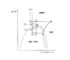
制御装置23は、高圧圧力センサ21、温度センサ22、中間圧圧力センサ24、第1電動膨張弁15、および第2電動膨張弁17等に通信接続されており、温度センサ22から送られてくる温度情報や、高圧圧力センサ21から送られてくる高圧圧力情報、中間圧圧力センサ24から送られてくる中間圧圧力情報に基づいて第1電動膨張弁15および第2電動膨張弁17の開度を制御する。また、この制御装置23には、冷房時において温度情報および高圧圧力情報に基づいて通常制御と冷媒冷却制御とを切り換える制御切換機能が搭載されている。通常制御では、COP等が向上するように第1電動膨張弁15および第2電動膨張弁17の開度が制御される。一方、冷媒冷却制御では、第1電動膨張弁15から流出した冷媒の状態が飽和線上の状態になり且つ臨界点近傍の状態にならないように第1電動膨張弁15および第2電動膨張弁17の開度が制御され、受液器16内の冷媒の状態が飽和状態に維持される。ここで、モリエ線図を利用して冷媒冷却制御について詳述する。図2には、二酸化炭素のモリエ線図上に本実施の形態に係る空気調和装置1の冷凍サイクルを表した図が示されている。なお、図2において、A→Bは圧縮行程を示し、B→C1,C2は冷却行程(B→C1は室外熱交換器13での冷却であり、C1→C2は内部熱交換器による冷却)を示し、C1,C2→D1,D2は第1膨張行程(第1電動膨張弁15による減圧)を示し、D1,D2→E1,E2は第2膨張行程(第2電動膨張弁17による減圧)を示し、E1,E2→Aは蒸発行程を示している。また、Kは臨界点を示している(なお、図2においてK点とD1点とは重なっている)。また、Tmは等温線である。さて、ここで、A→B→C1(K)→D1→E1→Aの冷凍サイクルを見ると、第1電動膨張弁15から流出した冷媒は臨界点近傍の状態となってしまう。しかし、本実施の形態に係る空気調和装置1には圧縮機11の吐出側に高圧圧力センサ21、室外熱交換器13の低温側近傍に温度センサ22が配置され、第1電動膨張弁15と受液器16との間に中間圧圧力センサ24が設けられているため、第1電動膨張弁15に流入する冷媒がC1点の状態になり、第1電動膨張弁15から流出した冷媒は臨界点近傍の状態になることを検知することができる。そこで、この空気調和装置1において第1電動膨張弁15に流入する冷媒がC1点の状態になり、第1電動膨張弁15から流出した冷媒は臨界点近傍の状態になると検知されると、第1電動膨張弁15と第2電動膨張弁17の開度を適宜調節して室外熱交換器13から流出した冷媒を冷却しその冷媒をC2点の状態にする。このようにすると、その冷凍サイクルは、A→B→C2→D2→E2→Aの冷凍サイクルへと変更される。つまり、冷媒がC2点の状態まで冷却されるため、冷媒の状態が飽和線近傍の状態になり且つ臨界点近傍の状態にならないようにすることができる。なお、本実施の形態では、制御装置23は、中間圧圧力センサ24が示す圧力が{臨界圧力(MPa)−0.3(MPa)}の圧力以下となるように第1電動膨張弁15および第2電動膨張弁17を制御する。ここで、{臨界圧力(MPa)−0.3(MPa)}という圧力は、次のように決定されている。発明者の行った試験の結果から第1電動膨張弁15と第2電動膨張弁17との間の圧力(以下、中間圧力という)の制御は冷媒の場合で目標値から±0.1MPa以内の程度の範囲で制御できることが明らかとなっている。そして、中間圧力が臨界点近傍にならないようにするためには、安全率を3として中間圧力の目標値を臨界圧力(MPa)−0.3(MPa)とするのが好ましい。
The
なお、本実施の形態において冷媒冷却制御の必要性がない場合には自動的に通常制御が行われるようになっている。 In the present embodiment, normal control is automatically performed when there is no need for refrigerant cooling control.
<空気調和装置の動作>
空気調和装置1の運転動作について、図1を用いて説明する。この空気調和装置1は、上述したように冷房運転および暖房運転を行うことが可能である。
<Operation of air conditioner>
The operation of the air conditioner 1 will be described with reference to FIG. As described above, the air conditioner 1 can perform a cooling operation and a heating operation.
(1)冷房運転
冷房運転時は、四路切換弁12が図1の実線で示される状態、すなわち、圧縮機11の吐出側が室外熱交換器13の高温側に接続され、かつ、圧縮機11の吸入側が内部熱交換器14を介して第2閉鎖弁19に接続された状態となる。また、このとき、第1閉鎖弁18および第2閉鎖弁19は開状態とされる。
(1) Cooling operation During the cooling operation, the four-
この冷媒回路2の状態で、圧縮機11を起動すると、ガス冷媒が、圧縮機11に吸入され、圧縮されて超臨界状態となった後、四路切換弁12を経由して室外熱交換器13に送られ、室外熱交換器13において冷却される。
When the
そして、この冷却された超臨界冷媒は、内部熱交換器14を経由して第1電動膨張弁15に送られる。なお、このとき、この超臨界冷媒は、内部熱交換器14の第1冷媒配管に流れる低温のガス冷媒により冷却される。そして、第1電動膨張弁15に送られた超臨界冷媒は、減圧されて飽和状態とされた後に受液器16を経由して第2電動膨張弁17に送られる。第2電動膨張弁17に送られた飽和状態の冷媒は、減圧されて液冷媒となった後に第1閉鎖弁18を経由して室内熱交換器31に供給され、室内空気を冷却するとともに蒸発されてガス冷媒となる。
The cooled supercritical refrigerant is sent to the first
そして、そのガス冷媒は、第2閉鎖弁19、内部熱交換器14、および四路切換弁12を経由して、再び、圧縮機11に吸入される。なお、このとき、このガス冷媒は、内部熱交換器14の第1冷媒配管に流れる高温の超臨界冷媒により加熱される。このようにして、冷房運転が行われる。なお、このとき、制御装置23は、上述したように温度情報および高圧圧力情報に基づいて通常制御と冷媒冷却制御とを適宜切り換える。
Then, the gas refrigerant is sucked into the
(2)暖房運転
暖房運転時は、四路切換弁12が図1の破線で示される状態、すなわち、圧縮機11の吐出側が第2閉鎖弁19に接続され、かつ、圧縮機11の吸入側が内部熱交換器14を介して室外熱交換器13のガス側に接続された状態となっている。また、このとき、第1閉鎖弁18および第2閉鎖弁19は開状態とされる。
(2) Heating operation During the heating operation, the four-
この冷媒回路2の状態で、圧縮機11を起動すると、ガス冷媒が、圧縮機11に吸入され、圧縮されて超臨界状態となった後、四路切換弁12および第2閉鎖弁19を経由して室内熱交換器31に供給される。
When the
そして、その超臨界冷媒は、室内熱交換器31において室内空気を加熱するとともに冷却される。冷却された超臨界冷媒は、第1閉鎖弁を通って第2電動膨張弁17に送られる。第2電動膨張弁17に送られた超臨界冷媒は、減圧されて飽和状態とされた後に受液器16を経由して第1電動膨張弁15に送られる。第1電動膨張弁15に送られた飽和状態の冷媒は、減圧されて液冷媒となった後に内熱交換器14を経由して室外熱交換器13に送られて、室外熱交換器13において蒸発されてガス冷媒となる。なお、このとき、このガス冷媒は、内部熱交換器14の第1冷媒配管に流れる高温の超臨界冷媒により加熱される。そして、このガス冷媒は、四路切換弁12を経由して、再び、圧縮機11に吸入される。このようにして、暖房運転が行われる。
Then, the supercritical refrigerant is cooled while heating the indoor air in the
<空気調和装置の特徴>
(1)
本実施の形態に係る空気調和装置1では、第1電動膨張弁15から流出した冷媒の状態が飽和線上の状態になり且つそのときの冷媒の圧力が{臨界圧力(MPa)−0.3(MPa)}の圧力以下となるように第1電動膨張弁15と第2電動膨張弁17とが制御される。このため、この空気調和装置1では、第1電動膨張弁15によって冷媒が飽和線近傍の状態まで膨張される場合に冷媒が臨界点近傍の状態となることを回避することができる。
<Characteristics of air conditioner>
(1)
In the air conditioner 1 according to the present embodiment, the state of the refrigerant flowing out of the first
(2)
本実施の形態に係る空気調和装置1では、冷媒冷却制御と通常制御とを切り換える機能が制御装置23に搭載されている。このため、この空気調和装置1では、COPを考慮した制御を実行することも可能となる。
(2)
In the air conditioner 1 according to the present embodiment, a function for switching between the refrigerant cooling control and the normal control is mounted on the
<変形例>
(A)
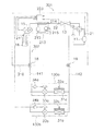
先の実施の形態では、本願発明が1台の室外ユニット10に対して1台の室内ユニット30が設けられるセパレート式の空気調和装置1に応用されたが、本願発明は図3に示されるな1台の室外ユニットに対して複数台の室内ユニットが設けられるマルチ式の空気調和装置101に応用されてもよい。なお、図3において、先の実施の形態に係る空気調和装置1の構成部品と同じ部品については同一の符号を用いている。また、図3において、符号102は冷媒回路を示し、符号110は室外ユニットを示し、符号130a,130bは室内ユニットを示し、符号31a,31bは室内熱交換器を示し、符号32a,32bは室内ファンを示し、符号33a,33bは第2電動膨張弁を示し、符号34a,34bは室内制御装置を示し、符号141,142は連絡配管を示している。なお、かかる場合、制御装置23は、室内制御装置34a,34bを介して第2電動膨張弁33a,33bを制御する。また、本変形例では第2電動膨張弁33a,33bが室内ユニット130a,130bに収容されたが、第2電動膨張弁33a,33bが室外ユニット110に収容されてもかまわない。
<Modification>
(A)
In the previous embodiment, the present invention was applied to the separate type air conditioner 1 in which one
(B)
先の実施の形態に係る空気調和装置1では、第10冷媒配管と第11冷媒配管とが近接配置された内部熱交換器14が採用されたが、内部熱交換器として二重管熱交換器が採用されてもよい。
(B)
In the air conditioner 1 according to the previous embodiment, the
(C)
先の実施の形態に係る空気調和装置1では、特に言及していなかったが、受液器16と第2電動膨張弁17との間に過冷却熱交換器(内部熱交換器であってもよい)を設けてもよい。なお、かかる場合、モリエ線図上の冷凍サイクルは図4に示されるようになる。図4において、A→Bは圧縮行程を示し、B→C1,C2は第1冷却行程を示し、C1,C2→D1,D2は第1膨張行程を示し、D1,D2→F1,F2は第2冷却行程(過冷却熱交換器による冷却)を示し、F1,F2→E1,E2は第2膨張行程を示し、E1,E2→Aは蒸発行程を示している。
(C)
Although not particularly mentioned in the air conditioner 1 according to the previous embodiment, a supercooling heat exchanger (even if it is an internal heat exchanger) is provided between the
(D)
先の実施の形態に係る空気調和装置1では、室外熱交換器13の低温側(あるいは液側)と第1電動膨張弁15との間に内部熱交換器14が形成されたが、これに代えて、第1冷媒配管に図5に示されるような外部冷却装置213を取り付けてもかまわない。この外部冷却装置213は、主に、冷却筒214、チラー215、および流体ポンプ216から構成されている。冷却筒214は、第10冷媒配管を囲う。チラー215は、冷却筒に流すための冷媒(例えば、水など)を冷却する。流体ポンプ216は、チラー215によって冷却された冷媒を冷却筒214に送出する。なお、冷却筒214に流入した冷媒は、再度、チラー215に入り、冷却される(つまり、冷媒は循環される)。なお、チラー215は冷媒を常に一定の温度に保っている。かかる場合、冷媒冷却制御では、第1電動膨張弁15から流出した冷媒が臨界点近傍の状態になると判断されると、制御装置223が流体ポンプ216を作動させて、あるいは流体ポンプ216の送出量を増加させて、第1電動膨張弁15から流出した冷媒の状態が飽和線上の状態になり且つそのときの冷媒の圧力が{臨界圧力(MPa)−0.3(MPa)}の圧力以下となるようにする。なお、ここでは、流体ポンプ216の送出量が一定とされ制御装置223がチラー215の冷却能力を高めるようにしてもよいし、制御装置223が流体ポンプ216の送出量およびチラー215の冷却能力を同時に高めるようにしてもよい。
(D)
In the air conditioner 1 according to the previous embodiment, the
なお、図5において、先の実施の形態に係る空気調和装置1の構成部品と同一の部品については同一の符号を付している。そして、新たに付されている符号201,202,210,223はそれぞれ空気調和装置、冷媒回路、室外ユニット、制御装置を示している。また、変形例(A)と同様に、この技術をマルチ式空気調和装置301に応用してもよい(図6参照)。なお、図6において先の実施の形態および変形例(A)に係る空気調和装置1,101の構成部品と同一の部品については同一の符号を付している。そして、新たに付されている符号302,310はそれぞれ冷媒回路、室外ユニットを示している。
In addition, in FIG. 5, the same code | symbol is attached | subjected about the component same as the component of the air conditioning apparatus 1 which concerns on previous embodiment.
(E)
先の実施の形態に係る空気調和装置1では圧縮機11の吐出側に高圧圧力センサ21が設けられたが、高圧圧力センサ21は取り除いてもよい。かかる場合、室外熱交換器13の低温側(あるいは液側)に配置される温度センサから得られる温度が所定の温度以上となった場合に第1電動膨張弁15から流出した冷媒の状態が飽和線上の状態になり且つそのときの冷媒の圧力が{臨界圧力(MPa)−0.3(MPa)}の圧力以下となるように第1電動膨張弁15および第2電動膨張弁17の開度を制御するようにすればよい。なお、このとき、第1電動膨張弁15の冷媒流出側と第2電動膨張弁17の冷媒流入側との間に温度センサを設けて中間温度を計測すると共に中間圧圧力センサ24によって中間圧を計測する必要がある。
(E)
In the air conditioner 1 according to the previous embodiment, the
(F)
先の実施の形態に係る空気調和装置1では、内部熱交換器14や、第1電動膨張弁15、受液器16、第2電動膨張弁17などが室外ユニット10に配置されていたが、これらの配置は特に限定されない。例えば、第2電動膨張弁17が室内ユニット30に配置されていてもよい。
(F)
In the air conditioner 1 according to the previous embodiment, the
(G)
先の実施の形態に係る空気調和装置1では、冷媒の減圧手段として電動膨張弁が採用されたが、これに代えて、膨張機などが採用されてもよい。
(G)
In the air-conditioning apparatus 1 according to the previous embodiment, the electric expansion valve is employed as the refrigerant decompression unit, but an expander or the like may be employed instead.
(H)
先の実施の形態に係る空気調和装置1では中間圧圧力センサ24が設けられたが、高圧圧力および第1電動膨張弁15の入口温度が決まっている場合には中間圧圧力センサ24を取り除いてもよい。かかる場合、第1電動膨張弁15の冷媒流出側と第2電動膨張弁17の冷媒流入側との間に温度センサを設け、飽和温度を測定するようにすればよい。
(H)
In the air conditioning apparatus 1 according to the previous embodiment, the
(I)
先の実施の形態に係る空気調和装置1では中間圧圧力センサ24が設けられたが、室内熱交換器31の出口側と圧縮機11の吸入側との間に低圧圧力センサを設け、第1電動膨張弁15の入口付近に温度センサを設ける場合には中間圧圧力センサ24を取り除いてもよい。かかる場合、第1電動膨張弁15および第2電動膨張弁17の開度−差圧特性を利用して中間圧を予測する。
(I)
In the air conditioner 1 according to the previous embodiment, the
(J)
先の実施の形態に係る空気調和装置1では温度センサ22が室外熱交換器13の低温側(あるいは液側)の口の近傍に設けられていたが、温度センサ22は第1電動膨張弁15の内部熱交換器側の口の近傍に設けられてもよい。
(J)
In the air conditioner 1 according to the previous embodiment, the
本発明に係る冷凍装置は、第1膨張機構によって冷媒が飽和線近傍の状態まで膨張される場合に冷媒が臨界点近傍の状態となることを回避することができるという特徴を有し、特に二酸化炭素などを冷媒として採用した冷凍装置に有益である。 The refrigeration apparatus according to the present invention has a feature that the refrigerant can be prevented from being in the vicinity of the critical point when the refrigerant is expanded to the state near the saturation line by the first expansion mechanism, and in particular, the dioxide dioxide. This is useful for refrigeration equipment that employs carbon as a refrigerant.
1,101,201,301 空気調和装置(冷凍装置)
11 圧縮機(圧縮機構)
13 室外熱交換器(放熱器)
14 内部熱交換器(冷媒冷却部)
15 第1電動膨張弁(第1膨張機構)
16 受液器
17,33a,33b 第2電動膨張弁(第2膨張機構)
22 温度センサ(温度検知部)
23,223 制御装置
31,31a,31b 室内熱交換器(蒸発器)
213 外部冷却装置(冷媒冷却部)
1, 101, 201, 301 Air conditioner (refrigeration equipment)
11 Compressor (compression mechanism)
13 Outdoor heat exchanger (heat radiator)
14 Internal heat exchanger (refrigerant cooling part)
15 First electric expansion valve (first expansion mechanism)
16
22 Temperature sensor (temperature detector)
23,223
213 External cooling device (refrigerant cooling part)
Claims (3)
前記圧縮機構の冷媒吐出側に接続される放熱器(13)と、
前記放熱器の出口側に接続される第1膨張機構(15)と、
前記放熱器の出口側と前記第1膨張機構の冷媒流入側との間に配置される冷媒冷却部(14,214)と、
前記第1膨張機構の冷媒流出側に接続される受液器(16)と、
前記受液器の出口側に接続される第2膨張機構(17,33a,33b)と、
前記第2膨張機構の冷媒流出側に接続されると共に前記圧縮機構の冷媒吸入側に接続される蒸発器(31,31a,31b)と、
前記圧縮機の吐出側に設けられている高圧圧力センサ(21)と、
前記放熱器の低温側に設けられている温度センサ(22)と、
前記第1膨張機構と前記受液器との間に設けられている中間圧圧力センサ(24)と、
前記温度センサの温度情報および前記中間圧圧力センサの圧力情報の圧力情報に基づいて、前記第1膨張機構から流出した冷媒が臨界点近傍の状態になると判断した場合、通常制御から冷媒冷却制御へと切り換える制御切換手段を有する制御部(23,223)と、
を備え、
前記通常制御ではCOPが向上するように、前記第1膨張機構および前記第2膨張機構の開度が制御され、
前記冷媒冷却制御では、前記第1膨張機構および前記第2膨張機構の開度及び/または前記冷媒冷却部を制御して、前記中間圧圧力センサが示す圧力が{臨界圧力(MPa)−0.3(MPa)}の圧力以下となるようにし、前記第1膨張機構から流出した冷媒の状態が飽和線上の状態になり且つ臨界点近傍の状態にならないように制御され、
前記受液器内の冷媒の状態を飽和状態に維持できるように制御される、
冷凍装置(1,101,201,301)。 A compression mechanism (11) for compressing the refrigerant;
A radiator (13) connected to the refrigerant discharge side of the compression mechanism;
A first expansion mechanism (15) connected to the outlet side of the radiator;
A refrigerant cooling section (14, 214) disposed between an outlet side of the radiator and a refrigerant inflow side of the first expansion mechanism;
A liquid receiver (16) connected to the refrigerant outflow side of the first expansion mechanism;
A second expansion mechanism (17, 33a, 33b) connected to the outlet side of the liquid receiver;
An evaporator (31, 31a, 31b) connected to the refrigerant outflow side of the second expansion mechanism and connected to the refrigerant suction side of the compression mechanism;
A high-pressure sensor (21) provided on the discharge side of the compressor;
A temperature sensor (22) provided on the low temperature side of the radiator;
An intermediate pressure sensor (24) provided between the first expansion mechanism and the liquid receiver;
Based on the pressure information of the temperature information of the temperature sensor and the pressure information of the intermediate pressure sensor, when it is determined that the refrigerant that has flowed out of the first expansion mechanism is in the vicinity of the critical point, the normal control is changed to the refrigerant cooling control. control unit having a control switching means for switching and (23,223),
With
In the normal control, the opening degrees of the first expansion mechanism and the second expansion mechanism are controlled so that COP is improved,
In the refrigerant cooling control, the degree of opening of the first expansion mechanism and the second expansion mechanism and / or the refrigerant cooling unit is controlled so that the pressure indicated by the intermediate pressure sensor is {critical pressure (MPa) -0. 3 (MPa)} or less, and the state of the refrigerant flowing out from the first expansion mechanism is controlled so as to be on the saturation line and not near the critical point,
It is controlled so that the state of the refrigerant in the receiver can be maintained in a saturated state.
Refrigeration equipment (1, 101, 201, 301).
請求項1に記載の冷凍装置(1,101)。 The refrigerant cooling section includes a refrigerant flowing through a first refrigerant pipe connecting an outlet side of the radiator and an inflow side of the first expansion mechanism, an outlet side of the evaporator and a refrigerant suction side of the compression mechanism. It is an internal heat exchanger (14) that performs heat exchange with the refrigerant flowing in the second refrigerant pipe to be connected.
The refrigeration apparatus (1, 101) according to claim 1.
請求項2に記載の冷凍装置。 In the refrigerant cooling control, when the temperature detected by the temperature detection unit is equal to or higher than a predetermined temperature, the refrigerant flowing out of the first expansion mechanism is in a state near the saturation line, and the pressure of the refrigerant is {critical The refrigerant is cooled by the refrigerant cooling unit so as to be equal to or lower than the pressure (MPa) −0.3 (MPa)}.
The refrigeration apparatus according to claim 2.
Priority Applications (5)
| Application Number | Priority Date | Filing Date | Title |
|---|---|---|---|
| JP2006246151A JP5145674B2 (en) | 2006-09-11 | 2006-09-11 | Refrigeration equipment |
| EP07793061.8A EP2068097B1 (en) | 2006-09-11 | 2007-08-28 | Refrigeration device |
| US12/439,934 US8176743B2 (en) | 2006-09-11 | 2007-08-28 | Refrigeration device |
| PCT/JP2007/066617 WO2008032558A1 (en) | 2006-09-11 | 2007-08-28 | Refrigeration device |
| CN2007800334528A CN101512249B (en) | 2006-09-11 | 2007-08-28 | Refrigeration device |
Applications Claiming Priority (1)
| Application Number | Priority Date | Filing Date | Title |
|---|---|---|---|
| JP2006246151A JP5145674B2 (en) | 2006-09-11 | 2006-09-11 | Refrigeration equipment |
Publications (3)
| Publication Number | Publication Date |
|---|---|
| JP2008064435A JP2008064435A (en) | 2008-03-21 |
| JP2008064435A5 JP2008064435A5 (en) | 2009-05-07 |
| JP5145674B2 true JP5145674B2 (en) | 2013-02-20 |
Family
ID=39183622
Family Applications (1)
| Application Number | Title | Priority Date | Filing Date |
|---|---|---|---|
| JP2006246151A Active JP5145674B2 (en) | 2006-09-11 | 2006-09-11 | Refrigeration equipment |
Country Status (5)
| Country | Link |
|---|---|
| US (1) | US8176743B2 (en) |
| EP (1) | EP2068097B1 (en) |
| JP (1) | JP5145674B2 (en) |
| CN (1) | CN101512249B (en) |
| WO (1) | WO2008032558A1 (en) |
Families Citing this family (13)
| Publication number | Priority date | Publication date | Assignee | Title |
|---|---|---|---|---|
| JP4225357B2 (en) * | 2007-04-13 | 2009-02-18 | ダイキン工業株式会社 | Refrigerant filling apparatus, refrigeration apparatus and refrigerant filling method |
| WO2009062526A1 (en) * | 2007-11-13 | 2009-05-22 | Carrier Corporation | Refrigerating system and method for refrigerating |
| JP5241872B2 (en) * | 2011-03-16 | 2013-07-17 | 三菱電機株式会社 | Refrigeration cycle equipment |
| WO2013160929A1 (en) * | 2012-04-23 | 2013-10-31 | 三菱電機株式会社 | Refrigeration cycle system |
| JP5933003B2 (en) * | 2012-07-20 | 2016-06-08 | 三菱電機株式会社 | Air conditioner |
| JP6058145B2 (en) * | 2013-08-28 | 2017-01-11 | 三菱電機株式会社 | Air conditioner |
| CN106461275B (en) * | 2014-07-23 | 2019-04-26 | 三菱电机株式会社 | Refrigerating circulatory device |
| JP6657613B2 (en) * | 2015-06-18 | 2020-03-04 | ダイキン工業株式会社 | Air conditioner |
| US11255580B2 (en) * | 2015-08-20 | 2022-02-22 | Lennox Industries Inc. | Carbon dioxide cooling system with subcooling |
| DE102017204116B4 (en) * | 2017-03-13 | 2022-06-15 | Audi Ag | Refrigeration system of a vehicle with a refrigerant circuit that can be operated as a refrigeration circuit for refrigeration and as a heat pump circuit for heating |
| US10962266B2 (en) * | 2018-10-24 | 2021-03-30 | Heatcraft Refrigeration Products, Llc | Cooling system |
| DE102019201427B4 (en) * | 2019-02-05 | 2022-01-13 | Audi Ag | Method for operating a refrigerant circuit of a refrigeration system of a vehicle |
| JP7168894B2 (en) * | 2021-03-30 | 2022-11-10 | ダイキン工業株式会社 | Heat source unit and refrigerator |
Family Cites Families (9)
| Publication number | Priority date | Publication date | Assignee | Title |
|---|---|---|---|---|
| JP3813702B2 (en) * | 1996-08-22 | 2006-08-23 | 株式会社日本自動車部品総合研究所 | Vapor compression refrigeration cycle |
| DE69732206T2 (en) * | 1996-08-22 | 2005-12-22 | Denso Corp., Kariya | Refrigeration system of the vapor compression type |
| JPH11142007A (en) * | 1997-11-06 | 1999-05-28 | Nippon Soken Inc | Refrigerating cycle |
| JP3614330B2 (en) * | 1999-10-20 | 2005-01-26 | シャープ株式会社 | Supercritical vapor compression refrigeration cycle |
| JP2001133058A (en) * | 1999-11-05 | 2001-05-18 | Matsushita Electric Ind Co Ltd | Refrigeration cycle |
| JP2003004316A (en) * | 2001-06-21 | 2003-01-08 | Matsushita Electric Ind Co Ltd | Method for controlling refrigeration unit |
| US7096679B2 (en) * | 2003-12-23 | 2006-08-29 | Tecumseh Products Company | Transcritical vapor compression system and method of operating including refrigerant storage tank and non-variable expansion device |
| JP4363997B2 (en) * | 2004-01-27 | 2009-11-11 | 三洋電機株式会社 | Refrigeration equipment |
| JP5324749B2 (en) * | 2006-09-11 | 2013-10-23 | ダイキン工業株式会社 | Refrigeration equipment |
-
2006
- 2006-09-11 JP JP2006246151A patent/JP5145674B2/en active Active
-
2007
- 2007-08-28 WO PCT/JP2007/066617 patent/WO2008032558A1/en active Application Filing
- 2007-08-28 EP EP07793061.8A patent/EP2068097B1/en active Active
- 2007-08-28 US US12/439,934 patent/US8176743B2/en active Active
- 2007-08-28 CN CN2007800334528A patent/CN101512249B/en active Active
Also Published As
| Publication number | Publication date |
|---|---|
| WO2008032558A1 (en) | 2008-03-20 |
| JP2008064435A (en) | 2008-03-21 |
| EP2068097A4 (en) | 2012-06-13 |
| EP2068097A1 (en) | 2009-06-10 |
| CN101512249A (en) | 2009-08-19 |
| US8176743B2 (en) | 2012-05-15 |
| CN101512249B (en) | 2011-02-16 |
| EP2068097B1 (en) | 2015-01-14 |
| US20100050672A1 (en) | 2010-03-04 |
Similar Documents
| Publication | Publication Date | Title |
|---|---|---|
| JP5145674B2 (en) | Refrigeration equipment | |
| JP2008064435A5 (en) | ||
| JP4973078B2 (en) | Refrigeration equipment | |
| JP5324749B2 (en) | Refrigeration equipment | |
| JP5332093B2 (en) | Refrigeration equipment | |
| JP4811204B2 (en) | Refrigeration equipment | |
| JP2008064436A5 (en) | ||
| JP2008064437A5 (en) | ||
| JP2008096093A5 (en) | ||
| JP2008064439A (en) | Air conditioner | |
| JP2008064438A5 (en) | ||
| JP6091614B2 (en) | Heat pump equipment | |
| CN109804209A (en) | Air-conditioning device | |
| JP4418936B2 (en) | Air conditioner | |
| JP6576603B1 (en) | Air conditioner | |
| JP2008039233A (en) | Refrigerating device | |
| JP7116346B2 (en) | Heat source unit and refrigerator | |
| WO2008069265A1 (en) | Air-conditioner | |
| US20220268498A1 (en) | Intermediate unit for refrigeration apparatus, and refrigeration apparatus | |
| JP4692002B2 (en) | Air conditioner | |
| JP2007107820A (en) | Air conditioner and air conditioner heat source unit used therefor |
Legal Events
| Date | Code | Title | Description |
|---|---|---|---|
| A521 | Written amendment |
Free format text: JAPANESE INTERMEDIATE CODE: A523 Effective date: 20090319 |
|
| A621 | Written request for application examination |
Free format text: JAPANESE INTERMEDIATE CODE: A621 Effective date: 20090724 |
|
| A131 | Notification of reasons for refusal |
Free format text: JAPANESE INTERMEDIATE CODE: A131 Effective date: 20110719 |
|
| A521 | Written amendment |
Free format text: JAPANESE INTERMEDIATE CODE: A523 Effective date: 20110916 |
|
| RD02 | Notification of acceptance of power of attorney |
Free format text: JAPANESE INTERMEDIATE CODE: A7422 Effective date: 20110916 |
|
| A131 | Notification of reasons for refusal |
Free format text: JAPANESE INTERMEDIATE CODE: A131 Effective date: 20120313 |
|
| A521 | Written amendment |
Free format text: JAPANESE INTERMEDIATE CODE: A523 Effective date: 20120425 |
|
| TRDD | Decision of grant or rejection written | ||
| A01 | Written decision to grant a patent or to grant a registration (utility model) |
Free format text: JAPANESE INTERMEDIATE CODE: A01 Effective date: 20121030 |
|
| A61 | First payment of annual fees (during grant procedure) |
Free format text: JAPANESE INTERMEDIATE CODE: A61 Effective date: 20121112 |
|
| R151 | Written notification of patent or utility model registration |
Ref document number: 5145674 Country of ref document: JP Free format text: JAPANESE INTERMEDIATE CODE: R151 |
|
| FPAY | Renewal fee payment (event date is renewal date of database) |
Free format text: PAYMENT UNTIL: 20151207 Year of fee payment: 3 |