JP5145673B2 - Laser processing method and laser processing apparatus - Google Patents
Laser processing method and laser processing apparatus Download PDFInfo
- Publication number
- JP5145673B2 JP5145673B2 JP2006234308A JP2006234308A JP5145673B2 JP 5145673 B2 JP5145673 B2 JP 5145673B2 JP 2006234308 A JP2006234308 A JP 2006234308A JP 2006234308 A JP2006234308 A JP 2006234308A JP 5145673 B2 JP5145673 B2 JP 5145673B2
- Authority
- JP
- Japan
- Prior art keywords
- adjustment
- processing
- laser
- workpiece
- laser beams
- Prior art date
- Legal status (The legal status is an assumption and is not a legal conclusion. Google has not performed a legal analysis and makes no representation as to the accuracy of the status listed.)
- Expired - Fee Related
Links
Images


Classifications
-
- B—PERFORMING OPERATIONS; TRANSPORTING
- B23—MACHINE TOOLS; METAL-WORKING NOT OTHERWISE PROVIDED FOR
- B23K—SOLDERING OR UNSOLDERING; WELDING; CLADDING OR PLATING BY SOLDERING OR WELDING; CUTTING BY APPLYING HEAT LOCALLY, e.g. FLAME CUTTING; WORKING BY LASER BEAM
- B23K26/00—Working by laser beam, e.g. welding, cutting or boring
- B23K26/02—Positioning or observing the workpiece, e.g. with respect to the point of impact; Aligning, aiming or focusing the laser beam
- B23K26/03—Observing, e.g. monitoring, the workpiece
- B23K26/032—Observing, e.g. monitoring, the workpiece using optical means
-
- B—PERFORMING OPERATIONS; TRANSPORTING
- B23—MACHINE TOOLS; METAL-WORKING NOT OTHERWISE PROVIDED FOR
- B23K—SOLDERING OR UNSOLDERING; WELDING; CLADDING OR PLATING BY SOLDERING OR WELDING; CUTTING BY APPLYING HEAT LOCALLY, e.g. FLAME CUTTING; WORKING BY LASER BEAM
- B23K26/00—Working by laser beam, e.g. welding, cutting or boring
- B23K26/02—Positioning or observing the workpiece, e.g. with respect to the point of impact; Aligning, aiming or focusing the laser beam
- B23K26/04—Automatically aligning, aiming or focusing the laser beam, e.g. using the back-scattered light
- B23K26/046—Automatically focusing the laser beam
- B23K26/048—Automatically focusing the laser beam by controlling the distance between laser head and workpiece
-
- B—PERFORMING OPERATIONS; TRANSPORTING
- B23—MACHINE TOOLS; METAL-WORKING NOT OTHERWISE PROVIDED FOR
- B23K—SOLDERING OR UNSOLDERING; WELDING; CLADDING OR PLATING BY SOLDERING OR WELDING; CUTTING BY APPLYING HEAT LOCALLY, e.g. FLAME CUTTING; WORKING BY LASER BEAM
- B23K26/00—Working by laser beam, e.g. welding, cutting or boring
- B23K26/02—Positioning or observing the workpiece, e.g. with respect to the point of impact; Aligning, aiming or focusing the laser beam
- B23K26/06—Shaping the laser beam, e.g. by masks or multi-focusing
- B23K26/0665—Shaping the laser beam, e.g. by masks or multi-focusing by beam condensation on the workpiece, e.g. for focusing
-
- B—PERFORMING OPERATIONS; TRANSPORTING
- B23—MACHINE TOOLS; METAL-WORKING NOT OTHERWISE PROVIDED FOR
- B23K—SOLDERING OR UNSOLDERING; WELDING; CLADDING OR PLATING BY SOLDERING OR WELDING; CUTTING BY APPLYING HEAT LOCALLY, e.g. FLAME CUTTING; WORKING BY LASER BEAM
- B23K26/00—Working by laser beam, e.g. welding, cutting or boring
- B23K26/08—Devices involving relative movement between laser beam and workpiece
- B23K26/083—Devices involving movement of the workpiece in at least one axial direction
- B23K26/0853—Devices involving movement of the workpiece in at least in two axial directions, e.g. in a plane
- B23K26/0861—Devices involving movement of the workpiece in at least in two axial directions, e.g. in a plane in at least in three axial directions
-
- B—PERFORMING OPERATIONS; TRANSPORTING
- B23—MACHINE TOOLS; METAL-WORKING NOT OTHERWISE PROVIDED FOR
- B23K—SOLDERING OR UNSOLDERING; WELDING; CLADDING OR PLATING BY SOLDERING OR WELDING; CUTTING BY APPLYING HEAT LOCALLY, e.g. FLAME CUTTING; WORKING BY LASER BEAM
- B23K26/00—Working by laser beam, e.g. welding, cutting or boring
- B23K26/50—Working by transmitting the laser beam through or within the workpiece
- B23K26/53—Working by transmitting the laser beam through or within the workpiece for modifying or reforming the material inside the workpiece, e.g. for producing break initiation cracks
Landscapes
- Physics & Mathematics (AREA)
- Optics & Photonics (AREA)
- Engineering & Computer Science (AREA)
- Plasma & Fusion (AREA)
- Mechanical Engineering (AREA)
- Chemical & Material Sciences (AREA)
- Chemical Kinetics & Catalysis (AREA)
- General Chemical & Material Sciences (AREA)
- Oil, Petroleum & Natural Gas (AREA)
- Laser Beam Processing (AREA)
Description
本発明は、加工対象物に対して加工用レーザ光を集光照射して該加工対象物を加工する方法および装置に関するものである。 The present invention relates to a method and apparatus for processing a processing object by condensing and irradiating a processing laser beam on the processing object.
加工対象物に対してレーザ光を集光照射して該加工対象物を加工する技術として、特許文献1に開示されたものが知られている。この特許文献1に開示された技術では、加工用の赤外レーザ光とは別に可視レーザ光をも加工対象物に向けて集光照射して、加工対象物における可視レーザ光の照射領域径を測定し、この測定した照射領域径に基づいて加工対象物の位置を測定し調整する。そして、位置調整後の加工対象物に対して加工用の赤外レーザ光を集光照射して、該加工対象物を加工する。
上記特許文献1に開示された技術では、加工対象物における位置調整用可視レーザ光の照射領域径の測定値に基づいて加工対象物の位置を調整することから、その位置調整の精度がよくない。 In the technique disclosed in Patent Literature 1, the position adjustment accuracy is not good because the position of the processing object is adjusted based on the measurement value of the irradiation area diameter of the position adjusting visible laser beam in the processing object. .
本発明は、上記問題点を解消する為になされたものであり、加工対象物の位置を精度よく調整した後に該加工対象物を加工することができるレーザ加工方法およびレーザ加工装置を提供することを目的とする。 The present invention has been made to solve the above-described problems, and provides a laser processing method and a laser processing apparatus capable of processing a processing object after adjusting the position of the processing object with high accuracy. With the goal.
本発明に係るレーザ加工方法は、加工対象物に対して加工用レーザ光を集光照射して加工対象物を加工するレーザ加工方法であって、複数の調整用レーザ光それぞれのビーム断面形状を特定形状として複数の調整用レーザ光を互いに異なる照射方向から1点で交差するように加工対象物に対して照射し、複数の調整用レーザ光の交差する位置と加工用レーザ光の集光点の位置の関係を設定し、加工対象物に照射される複数の調整用レーザ光それぞれの照射位置の目標位置を設定し、加工対象物における複数の調整用レーザ光それぞれの照射位置を測定するとともに、加工対象物における複数の調整用レーザ光それぞれのビームの照射領域形状を測定し、その測定した複数の調整用レーザ光それぞれの照射位置が、目標位置となるように、加工対象物の位置を調整するとともに、その測定した複数の調整用レーザ光それぞれのビームの照射領域形状が、予め設定された目標形状となるように、加工対象物の傾斜の方向及び傾斜の大きさを調整し、、その後、加工対象物に対して加工用レーザ光を集光照射することを特徴とする。加工用レーザ光の集光点と調整用レーザ光の交差点の位置は、一致しなくても良い。わざとずらして設定しても可である。要は、相対位置関係が分かっていればよい。
A laser processing method according to the present invention is a laser processing method for processing a processing target by condensing and irradiating the processing target with a processing laser beam, and a beam cross-sectional shape of each of a plurality of adjustment laser beams. As a specific shape, a plurality of adjustment laser beams are irradiated onto the object to be processed so that they intersect at different points from different irradiation directions, and a position where the plurality of adjustment laser beams intersect and a focusing point of the processing laser beams And setting the target position of each of the plurality of adjustment laser beams irradiated to the workpiece, and measuring the irradiation position of each of the plurality of adjustment laser beams on the workpiece the irradiation region shapes of a plurality of adjustment laser beam each of the beam at the object is measured, so that the plurality of adjustment laser beam each irradiation position measured becomes the target position, the processing As well as adjusting the position of the elephant product, the size of the illuminated area shape of the measured plurality of adjustment laser beam each beam, so that the preset target shape, the direction of inclination of the object and tilted After that, the laser beam for processing is condensed and irradiated to the processing object. The position of the converging point of the processing laser beam and the intersection of the adjustment laser beam may not coincide. It is also possible to set it deliberately. In short, it is only necessary to know the relative positional relationship.
本発明に係るレーザ加工装置は、加工対象物に対して加工用レーザ光を集光照射して加工対象物を加工するレーザ加工装置であって、加工用レーザ光を出力する加工用レーザ光源と、加工用レーザ光源から出力された加工用レーザ光を集光する集光光学系と、複数の調整用レーザ光それぞれのビーム断面形状を特定形状として複数の調整用レーザ光を出力するための調整用レーザ光源と、複数の調整用レーザ光を互いに異なる方向から1点で交差するように加工対象物に対して照射する調整用光学系と、加工対象物の位置を調整するとともに加工対象物の方位を調整する機能を有する調整部と、調整用光学系により照射された複数の調整用レーザ光それぞれの加工対象物における照射位置を測定するとともに、調整用光学系により照射された複数の調整用レーザ光それぞれの加工対象物におけるビームの照射領域形状を測定する測定部と、測定部により測定された複数の調整用レーザ光それぞれの照射位置が、複数の調整用レーザ光それぞれの予め設定された目標位置となるように、調整部による加工対象物の位置調整を制御するとともに、測定部により測定された複数の調整用レーザ光それぞれのビームの照射領域形状が、予め設定された目標形状となるように、調整部による加工対象物の傾斜の方向及び傾斜の大きさを制御する制御部とを備えることを特徴とする。 A laser processing apparatus according to the present invention is a laser processing apparatus that processes a processing object by condensing and irradiating the processing object with a processing laser beam, and a processing laser light source that outputs the processing laser light; , A condensing optical system for condensing the processing laser light output from the processing laser light source, and an adjustment for outputting a plurality of adjustment laser lights with the beam cross-sectional shape of each of the plurality of adjustment laser lights as a specific shape A laser light source for adjustment, an adjustment optical system for irradiating the workpiece with a plurality of laser beams for adjustment from different directions at one point, and adjusting the position of the workpiece and adjusting the position of the workpiece The adjustment unit having the function of adjusting the azimuth and the irradiation position of each of the plurality of adjustment laser beams irradiated by the adjustment optical system on the object to be processed are measured and irradiated by the adjustment optical system. A measuring unit for measuring the irradiation area shape of the beam in adjustment laser beam each of the object number, a plurality measured by the measuring unit adjustment laser beam each irradiation position, the laser beam of each for a plurality of adjustment The position adjustment of the workpiece by the adjustment unit is controlled so that the target position is set in advance, and the irradiation region shape of each of the plurality of adjustment laser beams measured by the measurement unit is set in advance. And a control unit that controls a direction of inclination and a magnitude of the inclination of the workpiece by the adjustment unit so as to obtain a target shape.
本発明によれば、加工対象物の位置を精度よく調整した後に該加工対象物を加工することができる。 According to the present invention, the processing object can be processed after the position of the processing object is accurately adjusted.
以下、添付図面を参照して、本発明を実施するための最良の形態を詳細に説明する。なお、図面の説明において同一の要素には同一の符号を付し、重複する説明を省略する。 The best mode for carrying out the present invention will be described below in detail with reference to the accompanying drawings. In the description of the drawings, the same elements are denoted by the same reference numerals, and redundant description is omitted.
(第1実施形態)
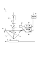
先ず、本発明の第1実施形態に係るレーザ加工方法およびレーザ加工装置について説明する。図1は、第1実施形態に係るレーザ加工装置1の構成図である。この図に示されるレーザ加工装置1は、加工対象物9に対して加工用レーザ光L0を集光照射して該加工対象物9を加工する装置であって、加工用レーザ光源10、ビームエキスパンダ21、ミラー22、集光レンズ23、調整用レーザ光源30、ミラー41、ミラー42、調整部50、CCDカメラ61、結像レンズ62および制御部70を備える。
(First embodiment)
First, a laser processing method and a laser processing apparatus according to a first embodiment of the present invention will be described. FIG. 1 is a configuration diagram of a laser processing apparatus 1 according to the first embodiment. The laser processing apparatus 1 shown in this figure, the processing laser beam L 0 by irradiating light collecting to a device for machining the
加工用レーザ光源10は、加工対象物9を加工する為の加工用レーザ光L0を出力するものであり、例えば波長1064nmのレーザ光を出力するYAGレーザ光源である。ビームエキスパンダ21、ミラー22および集光レンズ23は、加工用レーザ光源10から出力された加工用レーザ光L0を集光する加工用光学系を構成している。
The processing
ビームエキスパンダ21は、加工用レーザ光源10から出力された加工用レーザ光L0のビーム径を拡大する。ミラー22は、ビームエキスパンダ21から出力された加工用レーザ光L0を反射させて、その反射後の加工用レーザ光L0を加工対象物9の表面に対して垂直に入射させる。集光レンズ23は、ミラー22と加工対象物9との間に設けられ、ミラー22により反射された加工用レーザ光L0を集光する。
The beam expander 21 expands the beam diameter of the processing laser light L 0 output from the processing
調整用レーザ光源30は、調整用レーザ光を出力するものである。調整用レーザ光源30から出力される調整用レーザ光の波長は、加工用レーザ光源10から出力された加工用レーザ光の波長と同一であってもよいし相違していてもよく、また、可視域であってもよいし赤外域であってもよい。ただし、調整用レーザ光源30から出力される調整用レーザ光は、加工用途ではないので、加工用レーザ光の波長と同一である場合には、集光されることはなく、或いは、低パワーとされる。
The adjustment
ミラー41およびミラー42は、調整用レーザ光源30から出力された2つの調整用レーザ光L1,L2を互いに異なる方向から1点で交差するように加工対象物9に対して照射する調整用光学系を構成している。ミラー41は、調整用レーザ光源30から出力された調整用レーザ光を2分岐して、そのうちの一方の調整用レーザ光L1を加工対象物9に対して照射し、他方の調整用レーザ光L2をミラー42へ入射させる。ミラー42は、ミラー41から到達した調整用レーザ光L2を反射させて、その反射後の調整用レーザ光L2を加工対象物9に対して照射する。
The
なお、加工対象物9に対して照射される調整用レーザ光L1,L2それぞれのビーム断面形状は、特定形状(例えば、円形、楕円形、正方形、長方形、十字形、等)とされる。
Note that the beam cross-sectional shapes of the adjustment laser beams L 1 and L 2 irradiated to the
調整部50は、加工対象物9の位置を調整するものであり、また、加工対象物9の傾斜の方向及び傾斜の大きさも調整することが可能である。なお、加工対象物9の位置は、少なくとも、集光レンズ23の光軸に沿う方向に調整され得る。
The
CCDカメラ61および結像レンズ62は、調整用光学系により照射された2つの調整用レーザ光L1,L2それぞれの加工対象物9における照射位置を測定する測定部を構成している。結像レンズ62は、加工対象物9の表面に照射された調整用レーザ光L1,L2の反射光を、CCDカメラ61の撮像面に結像させる。そして、CCDカメラ61は、加工対象物9の表面における調整用レーザ光L1,L2の照射の様子を撮像する。また、調整用光学系により照射された2つの調整用レーザ光L1,L2それぞれの加工対象物9における照射領域形状をも測定することができる。
The
制御部70は、CCDカメラ61による測定結果に基づいて、調整部50による加工対象物9の位置調整および傾斜調整を制御する。すなわち、制御部70は、CCDカメラ61により測定された2つの調整用レーザ光L1,L2それぞれの照射位置が、2つの調整用レーザ光L1,L2それぞれの照射方向および加工用レーザ光L0の集光位置の間の関係に基づいて予め設定された目標位置となるように、調整部50による加工対象物9の位置調整を制御する。また、制御部70は、CCDカメラ61により測定された2つの調整用レーザ光L1,L2それぞれの照射領域形状が、2つの調整用レーザ光L1,L2それぞれの照射方向に基づいて予め設定された目標形状となるように、調整部50による加工対象物9の傾斜調整を制御する。さらに、制御部70は、加工用レーザ光源10および調整用レーザ光源30それぞれのレーザ光出力をも制御する。
The
次に、第1実施形態に係るレーザ加工装置1の動作例について説明するとともに、第1実施形態に係るレーザ加工方法について説明する。なお、以下に説明する動作は、制御部70による制御の下に行われる。
Next, an operation example of the laser processing apparatus 1 according to the first embodiment will be described, and a laser processing method according to the first embodiment will be described. The operations described below are performed under the control of the
加工用レーザ光源10から加工用レーザ光が出力される前に、調整用レーザ光源30から調整用レーザ光が出力される。調整用レーザ光源30から出力されたレーザ光は、ミラー41およびミラー42を含む調整用光学系により2分岐されて調整用レーザ光L1,L2とされる。そして、これら調整用レーザ光L1,L2は、調整用光学系により、互いに異なる方向から1点で交差するように加工対象物9に対して照射される。調整用光学系により照射された2つの調整用レーザ光L1,L2それぞれの加工対象物9における照射位置が、結像レンズ62を介してCCDカメラ61による撮像結果に基づいて測定される。
Before the processing laser light is output from the processing
この測定された2つの調整用レーザ光L1,L2それぞれの照射位置が、2つの調整用レーザ光L1,L2それぞれの照射方向および加工用レーザ光L0の集光位置の間の関係に基づいて予め設定された目標位置となるように、調整部50による加工対象物9の位置調整が制御される。例えば、2つの調整用レーザ光L1,L2の交差位置が加工用レーザ光L0の集光位置と一致しているように光学系が調整されている場合には、測定された2つの調整用レーザ光L1,L2それぞれの照射位置が一致するように、調整部50による加工対象物9の位置調整が制御される。
The two measured adjustment laser beam L 1, L 2 of each irradiation position, between the focusing position of the two adjustment laser beam L 1, L 2 respectively illumination direction and the processing laser beam L 0 The position adjustment of the
その後、加工用レーザ光源10から加工用レーザ光が出力される。加工用レーザ光源10から出力された加工用レーザ光L0は、ビームエキスパンダ21,ミラー22および集光レンズ23を含む加工用光学系により、加工対象物9に集光照射される。このようにすることにより、加工対象物9の位置を精度よく調整した後に該加工対象物9を加工することができる。
Thereafter, a processing laser light is output from the processing
また、加工対象物9の傾斜の方向及び傾斜の大きさは以下のようにして調整され得る。すなわち、調整用光学系により照射された2つの調整用レーザ光L1,L2それぞれの加工対象物9における照射領域形状が、結像レンズ62を介してCCDカメラ61による撮像結果に基づいて測定される。この測定された2つの調整用レーザ光L1,L2それぞれの照射領域形状が、2つの調整用レーザ光L1,L2それぞれの照射方向に基づいて予め設定された目標形状となるように、調整部50による加工対象物9の傾斜調整が制御される。
Further, the direction of inclination and the magnitude of the inclination of the
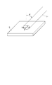
例えば、2つの調整用レーザ光L1,L2それぞれのビーム断面形状が円形である場合、図2に示されるように、加工対象物9における照射領域形状は一般に楕円形となる。この楕円形の短軸長さをXとし、長軸長さをYとすると、加工対象物9表面に対する調整用レーザ光の入射角θは「θ=arccos(X/Y)」なる式で表される。加工用レーザ光L0の照射方向と調整用レーザ光の照射方向とがなす角度が45度であるとすると、加工対象物9表面に対する調整用レーザ光の入射角θ(=arccos(X/Y))が45度となるように加工対象物9の傾斜の方向及び傾斜の大きさが調整されると、加工対象物9に対して加工用レーザ光L0が垂直に照射される。
For example, when the beam cross-sectional shapes of the two adjustment laser beams L 1 and L 2 are circular, as shown in FIG. 2, the irradiation region shape on the
また、加工対象物9における加工用レーザ光L0の集光位置は、加工対象物9の表面であってもよいし、加工対象物9の内部であってもよい。図3に示されるように、加工用レーザ光L0の集光位置が加工対象物9の内部であって深さHであるとし、加工対象物9表面における2つの調整用レーザ光L1,L2それぞれの照射位置の間隔がWであるとすると、「W=2Htanθ」なる式が成り立つ。したがって、所望の深さHが得られる照射位置間隔Wとなるように、加工対象物9の位置が調整されればよい。
Further, the focusing position of the processing laser beam L 0 on the
(第2実施形態)
次に、本発明の第2実施形態に係るレーザ加工方法およびレーザ加工装置について説明する。図4は、第2実施形態に係るレーザ加工装置2の構成図である。この図に示されるレーザ加工装置2は、加工対象物9に対して加工用レーザ光L0を集光照射して該加工対象物9を加工する装置であって、加工用レーザ光源10、ビームエキスパンダ21、ミラー22、集光レンズ23、調整用レーザ光源31、調整用レーザ光源32、調整部50、CCDカメラ61、結像レンズ62および制御部70を備える。
(Second Embodiment)
Next, a laser processing method and a laser processing apparatus according to the second embodiment of the present invention will be described. FIG. 4 is a configuration diagram of the
図1に示した第1実施形態に係るレーザ加工装置1の構成と比較すると、この図4に示される第2実施形態に係るレーザ加工装置2は、調整用レーザ光源30に替えて2つの調整用レーザ光源31,32を備える点で相違し、また、調整用レーザ光源31,32から出力される調整用レーザ光L1,L2を互いに異なる方向から1点で交差するように加工対象物9に対して照射する調整用光学系がミラーを有する必要が無い点で相違する。このように構成される第2実施形態に係るレーザ加工装置2も、第1実施形態に係るレーザ加工装置1と同様に動作し同様の効果を奏することができる。
Compared with the configuration of the laser processing apparatus 1 according to the first embodiment shown in FIG. 1, the
また、この第2実施形態では、調整用レーザ光源31から出力される調整用レーザ光L1と、調整用レーザ光源32から出力される調整用レーザ光L2とは、互いに同じ波長であってもよいし、互いに異なる波長であってもよい。互いに異なる波長とする場合、例えば、調整用レーザ光源31から出力される調整用レーザ光L1の波長が633nmであり、調整用レーザ光源32から出力される調整用レーザ光L2の波長が355nmである。この場合、加工対象物9における調整用レーザ光L1,L2それぞれの照射領域は色によって識別することができ、また、両者の照射領域が重なる領域についても色によって識別することができる。
In the second embodiment, the adjustment laser light L 1 output from the adjustment
(変形例)
本発明は、上記実施形態に限定されるものではなく、種々の変形が可能である。例えば、加工対象物に照射する調整用レーザ光は3つ以上であってもよい。3つ以上の調整用レーザ光を互いに異なる照射方向から1点で交差するように加工対象物に対して照射することにより、加工対象物の位置および傾斜の方向及び傾斜の大きさの調整が更に容易かつ高精度に可能となる。
(Modification)
The present invention is not limited to the above embodiment, and various modifications can be made. For example, three or more adjustment laser beams may be applied to the object to be processed. By irradiating the object to be processed with three or more adjustment laser beams so as to intersect at different points from different irradiation directions, the position of the object to be processed, the direction of the inclination, and the size of the inclination can be further adjusted. Easy and highly accurate.
1,2…レーザ加工装置、9…加工対象物、10…加工用レーザ光源、21…ビームエキスパンダ、22…ミラー、23…集光レンズ、30〜32…調整用レーザ光源、41…ミラー、42…ミラー、50…調整部、61…CCDカメラ、62…結像レンズ、70…制御部。
DESCRIPTION OF
Claims (2)
複数の調整用レーザ光それぞれのビーム断面形状を特定形状として前記複数の調整用レーザ光を互いに異なる照射方向から1点で交差するように前記加工対象物に対して照射し、
前記複数の調整用レーザ光の交差する位置と前記加工用レーザ光の集光点の位置の関係を設定し、
前記加工対象物に照射される前記複数の調整用レーザ光それぞれの照射位置の目標位置を設定し、
前記加工対象物における前記複数の調整用レーザ光それぞれの照射位置を測定するとともに、前記加工対象物における前記複数の調整用レーザ光それぞれのビームの照射領域形状を測定し、
その測定した前記複数の調整用レーザ光それぞれの照射位置が、前記目標位置となるように、前記加工対象物の位置を調整するとともに、その測定した前記複数の調整用レーザ光それぞれのビームの照射領域形状が、予め設定された目標形状となるように、前記加工対象物の傾斜の方向及び傾斜の大きさを調整し、
その後、前記加工対象物に対して前記加工用レーザ光を集光照射する
ことを特徴とするレーザ加工方法。 A laser processing method for processing a processing object by condensing and irradiating a processing laser beam on the processing object,
Irradiating the workpiece with the beam cross-sectional shape of each of the plurality of adjustment laser beams as a specific shape so that the plurality of adjustment laser beams intersect at one point from different irradiation directions;
Set the relationship between the position where the plurality of adjustment laser beams intersect and the position of the focusing point of the processing laser beam,
Set a target position of each irradiation position of the plurality of adjustment laser beams irradiated to the workpiece,
While measuring the irradiation position of each of the plurality of adjustment laser beams on the workpiece, and measuring the irradiation region shape of each of the plurality of adjustment laser beams on the workpiece,
The position of the workpiece is adjusted so that the measured irradiation positions of the plurality of adjustment laser beams are the target positions, and the irradiation of the measured beams of the plurality of adjustment laser beams is performed. Adjust the direction of inclination and the size of the inclination of the workpiece so that the region shape becomes a preset target shape,
Then, the laser beam for processing is condensed and applied to the object to be processed.
加工用レーザ光を出力する加工用レーザ光源と、
前記加工用レーザ光源から出力された加工用レーザ光を集光する集光光学系と、
複数の調整用レーザ光それぞれのビーム断面形状を特定形状として前記複数の調整用レーザ光を出力するための調整用レーザ光源と、
前記複数の調整用レーザ光を互いに異なる方向から1点で交差するように前記加工対象物に対して照射する調整用光学系と、
前記加工対象物の位置を調整するとともに前記加工対象物の方位を調整する機能を有する調整部と、
前記調整用光学系により照射された前記複数の調整用レーザ光それぞれの前記加工対象物における照射位置を測定するとともに、前記調整用光学系により照射された前記複数の調整用レーザ光それぞれの前記加工対象物におけるビームの照射領域形状を測定する測定部と、
前記測定部により測定された前記複数の調整用レーザ光それぞれの照射位置が、前記複数の調整用レーザ光それぞれの予め設定された目標位置となるように、前記調整部による前記加工対象物の位置調整を制御するとともに、前記測定部により測定された前記複数の調整用レーザ光それぞれのビームの照射領域形状が、予め設定された目標形状となるように、前記調整部による前記加工対象物の傾斜の方向及び傾斜の大きさを制御する制御部と
を備えることを特徴とするレーザ加工装置。
A laser processing apparatus for processing a processing object by condensing and irradiating a processing laser beam on the processing object,
A processing laser light source for outputting a processing laser beam;
A condensing optical system for condensing the processing laser light output from the processing laser light source;
An adjustment laser light source for outputting the plurality of adjustment laser lights with a beam cross-sectional shape of each of the plurality of adjustment laser lights as a specific shape;
An adjustment optical system for irradiating the object to be processed so that the plurality of adjustment laser beams intersect at a single point from different directions;
An adjustment unit having a function of adjusting the position of the workpiece and adjusting the orientation of the workpiece;
The irradiation position of each of the plurality of adjustment laser beams irradiated by the adjustment optical system is measured on the object to be processed, and the processing of each of the plurality of adjustment laser beams irradiated by the adjustment optical system is performed. A measurement unit for measuring the shape of the irradiation region of the beam on the object;
The position of the object to be processed by the adjustment unit so that the irradiation position of each of the plurality of adjustment laser beams measured by the measurement unit becomes a preset target position of each of the plurality of adjustment laser beams. The adjustment unit controls the adjustment, and the adjustment unit tilts the workpiece so that the irradiation area shape of each of the plurality of adjustment laser beams measured by the measurement unit becomes a preset target shape. A laser processing apparatus comprising: a control unit that controls the direction and the magnitude of the inclination.
Priority Applications (2)
| Application Number | Priority Date | Filing Date | Title |
|---|---|---|---|
| JP2006234308A JP5145673B2 (en) | 2006-08-30 | 2006-08-30 | Laser processing method and laser processing apparatus |
| US11/878,973 US8294123B2 (en) | 2006-08-30 | 2007-07-30 | Laser processing method and laser processing apparatus |
Applications Claiming Priority (1)
| Application Number | Priority Date | Filing Date | Title |
|---|---|---|---|
| JP2006234308A JP5145673B2 (en) | 2006-08-30 | 2006-08-30 | Laser processing method and laser processing apparatus |
Publications (2)
| Publication Number | Publication Date |
|---|---|
| JP2008055455A JP2008055455A (en) | 2008-03-13 |
| JP5145673B2 true JP5145673B2 (en) | 2013-02-20 |
Family
ID=39238816
Family Applications (1)
| Application Number | Title | Priority Date | Filing Date |
|---|---|---|---|
| JP2006234308A Expired - Fee Related JP5145673B2 (en) | 2006-08-30 | 2006-08-30 | Laser processing method and laser processing apparatus |
Country Status (2)
| Country | Link |
|---|---|
| US (1) | US8294123B2 (en) |
| JP (1) | JP5145673B2 (en) |
Families Citing this family (11)
| Publication number | Priority date | Publication date | Assignee | Title |
|---|---|---|---|---|
| EP2838688B1 (en) * | 2012-04-17 | 2019-09-18 | Koninklijke Philips N.V. | Lighting apparatus |
| JP6748933B2 (en) * | 2015-04-22 | 2020-09-02 | 株式会社Ihi | Terahertz irradiation position visualization device |
| KR101716369B1 (en) * | 2015-10-19 | 2017-03-27 | 주식회사 이오테크닉스 | Auto inspection apparatus and method of laser processing apparatus |
| US20170160538A1 (en) * | 2015-12-07 | 2017-06-08 | Nike, Inc. | Laser siping apparatus |
| JP6342949B2 (en) * | 2016-05-17 | 2018-06-13 | ファナック株式会社 | Laser processing apparatus and laser processing method for performing laser processing while suppressing reflected light |
| CN106670652A (en) * | 2016-12-29 | 2017-05-17 | 苏州逸美德科技有限公司 | Laser coaxial processing device and method |
| DE102017207421A1 (en) * | 2017-05-03 | 2018-11-08 | Trumpf Werkzeugmaschinen Gmbh + Co. Kg | Method and distance adjusting device for adjusting the distance of a laser processing head to a workpiece surface and computer program product |
| CN110099229B (en) | 2018-01-30 | 2023-04-28 | 松下知识产权经营株式会社 | Image pickup apparatus |
| JP2020066039A (en) * | 2018-10-26 | 2020-04-30 | カンタツ株式会社 | Laser processing device, laser processing device control method and laser processing device control program |
| JP7208703B2 (en) * | 2019-05-13 | 2023-01-19 | 株式会社ディスコ | Adjustment method |
| GB201913631D0 (en) * | 2019-09-20 | 2019-11-06 | Alltec Angewandte Laserlicht Tech Gesellschaft Mit Beschraenkter Haftung | Electromagnetic radiation system |
Family Cites Families (36)
| Publication number | Priority date | Publication date | Assignee | Title |
|---|---|---|---|---|
| US4272193A (en) * | 1979-04-13 | 1981-06-09 | The United States Of America As Represented By The United States Department Of Energy | Method and apparatus for timing of laser beams in a multiple laser beam fusion system |
| JPH0642993B2 (en) * | 1986-10-28 | 1994-06-08 | 三菱電機株式会社 | Distance measuring device |
| US4815819A (en) * | 1987-04-30 | 1989-03-28 | Christopher A. Mayhew | Method for obtaining images for use in displaying a three-dimensional illusion and related image recording medium |
| US4888490A (en) * | 1988-05-24 | 1989-12-19 | University Of Southern California | Optical proximity apparatus and method using light sources being modulated at different frequencies |
| JPH0343707A (en) * | 1989-07-11 | 1991-02-25 | Canon Inc | Scanning optical device |
| US5545160A (en) * | 1990-08-14 | 1996-08-13 | O'rourke; Daniel K. | Computer oriented stereotactic microneurological surgery |
| US5209813A (en) * | 1990-10-24 | 1993-05-11 | Hitachi, Ltd. | Lithographic apparatus and method |
| US5311288A (en) * | 1992-07-06 | 1994-05-10 | Opal Technologies Ltd. | Method and apparatus for detecting surface deviations from a reference plane |
| US5643801A (en) * | 1992-11-06 | 1997-07-01 | Semiconductor Energy Laboratory Co., Ltd. | Laser processing method and alignment |
| JP3255469B2 (en) * | 1992-11-30 | 2002-02-12 | 三菱電機株式会社 | Laser thin film forming equipment |
| JP3060779B2 (en) * | 1993-03-24 | 2000-07-10 | 日産自動車株式会社 | Laser processing equipment |
| FR2709657B1 (en) * | 1993-09-07 | 1995-12-01 | Deemed Int Sa | Optical designation device, in particular for microsurgery operation. |
| JPH07218261A (en) * | 1994-02-03 | 1995-08-18 | Nikon Corp | Laser projector |
| GB9611170D0 (en) * | 1996-05-29 | 1996-07-31 | Sls Wales Ltd | Reduction of vascular blemishes by selective thermolysis |
| JPH10133145A (en) | 1996-10-28 | 1998-05-22 | Furukawa Co Ltd | Guide light system for laser irradiating device |
| WO1998044718A2 (en) * | 1997-04-01 | 1998-10-08 | Agris-Schoen Vision Systems, Inc. | High-precision-resolution image acquisision apparatus and method |
| US6107637A (en) * | 1997-08-11 | 2000-08-22 | Hitachi, Ltd. | Electron beam exposure or system inspection or measurement apparatus and its method and height detection apparatus |
| US20060060781A1 (en) * | 1997-08-11 | 2006-03-23 | Masahiro Watanabe | Charged-particle beam apparatus and method for automatically correcting astigmatism and for height detection |
| US6483580B1 (en) * | 1998-03-06 | 2002-11-19 | Kla-Tencor Technologies Corporation | Spectroscopic scatterometer system |
| DE19838518A1 (en) * | 1998-08-25 | 2000-03-02 | Bosch Gmbh Robert | arrangement |
| WO2000052417A1 (en) * | 1999-02-26 | 2000-09-08 | Anritsu Corporation | Apparatus and method for measuring displacement |
| JP4124396B2 (en) * | 1999-12-17 | 2008-07-23 | 独立行政法人科学技術振興機構 | Hologram manufacturing method and apparatus |
| GB2367375B (en) * | 2000-09-11 | 2004-09-01 | Mark Rogers | Laser range estimation aid |
| JP4659300B2 (en) * | 2000-09-13 | 2011-03-30 | 浜松ホトニクス株式会社 | Laser processing method and semiconductor chip manufacturing method |
| US7046353B2 (en) * | 2001-12-04 | 2006-05-16 | Kabushiki Kaisha Topcon | Surface inspection system |
| TWI326626B (en) * | 2002-03-12 | 2010-07-01 | Hamamatsu Photonics Kk | Laser processing method |
| WO2004050291A1 (en) * | 2002-12-05 | 2004-06-17 | Hamamatsu Photonics K.K. | Laser processing device |
| JP2004188422A (en) * | 2002-12-06 | 2004-07-08 | Hamamatsu Photonics Kk | Device and method for machining laser beam |
| US7104689B2 (en) * | 2003-01-22 | 2006-09-12 | Instrumentarium Corporation | Positioning device and method in X-ray imaging systems |
| JP4601965B2 (en) * | 2004-01-09 | 2010-12-22 | 浜松ホトニクス株式会社 | Laser processing method and laser processing apparatus |
| JP2005274925A (en) * | 2004-03-24 | 2005-10-06 | Pioneer Electronic Corp | Focusing method and focusing device |
| JP2005297012A (en) * | 2004-04-13 | 2005-10-27 | Disco Abrasive Syst Ltd | Laser beam machining apparatus |
| JP4389791B2 (en) * | 2004-08-25 | 2009-12-24 | セイコーエプソン株式会社 | Fine structure manufacturing method and exposure apparatus |
| CN1799974B (en) * | 2004-12-16 | 2010-09-01 | 海德堡印刷机械股份公司 | Apparatus for adjusting relative interval between sheet and guiding device |
| JP4804911B2 (en) * | 2005-12-22 | 2011-11-02 | 浜松ホトニクス株式会社 | Laser processing equipment |
| JP4954653B2 (en) * | 2006-09-19 | 2012-06-20 | 浜松ホトニクス株式会社 | Laser processing method |
-
2006
- 2006-08-30 JP JP2006234308A patent/JP5145673B2/en not_active Expired - Fee Related
-
2007
- 2007-07-30 US US11/878,973 patent/US8294123B2/en not_active Expired - Fee Related
Also Published As
| Publication number | Publication date |
|---|---|
| US8294123B2 (en) | 2012-10-23 |
| US20080210886A1 (en) | 2008-09-04 |
| JP2008055455A (en) | 2008-03-13 |
Similar Documents
| Publication | Publication Date | Title |
|---|---|---|
| JP5145673B2 (en) | Laser processing method and laser processing apparatus | |
| JP2003200286A (en) | Laser microspot welding equipment | |
| JP4429974B2 (en) | Laser processing method and apparatus | |
| JP2009082958A (en) | Laser beam machining apparatus and axicon lens | |
| JP3227106B2 (en) | Inner diameter measuring method and inner diameter measuring device | |
| JP5058624B2 (en) | Laser microscope | |
| JP2005028428A (en) | Laser beam machining device | |
| JPH11218686A (en) | Optical image recording device and method utilising the device | |
| KR101279578B1 (en) | Auto focusing apparatus for laser processing and auto focusing method using the same | |
| JP5328406B2 (en) | Laser processing method, laser processing apparatus, and solar panel manufacturing method | |
| JP2007237200A (en) | Laser beam machining system and laser beam machining method | |
| US8441652B2 (en) | Profile measuring apparatus, method for measuring profile, and method for manufacturing product | |
| JP2006007257A (en) | Laser beam machining apparatus | |
| KR101361776B1 (en) | Auto focusing apparatus for laser processing and auto focusing method using the same | |
| KR102050765B1 (en) | Multi modal laser machining system | |
| JP3179322B2 (en) | High power laser transmission method and apparatus | |
| KR101742132B1 (en) | Laser processing apparauts | |
| JPH05332934A (en) | Spectroscope | |
| JP2008310107A (en) | Focusing device and machining device equipped with the same | |
| JP5142916B2 (en) | Laser processing method and laser processing apparatus | |
| JP2020082149A (en) | Laser irradiation system | |
| TWI586468B (en) | Method and apparatus of laser processing | |
| JP6389759B2 (en) | Non-contact edge shape measuring method and apparatus | |
| JP2007086095A (en) | Surface inspecting device | |
| JPS61186186A (en) | Laser beam condensing device |
Legal Events
| Date | Code | Title | Description |
|---|---|---|---|
| A621 | Written request for application examination |
Free format text: JAPANESE INTERMEDIATE CODE: A621 Effective date: 20090409 |
|
| A977 | Report on retrieval |
Free format text: JAPANESE INTERMEDIATE CODE: A971007 Effective date: 20110607 |
|
| A131 | Notification of reasons for refusal |
Free format text: JAPANESE INTERMEDIATE CODE: A131 Effective date: 20110802 |
|
| A521 | Request for written amendment filed |
Free format text: JAPANESE INTERMEDIATE CODE: A523 Effective date: 20110907 |
|
| A131 | Notification of reasons for refusal |
Free format text: JAPANESE INTERMEDIATE CODE: A131 Effective date: 20120321 |
|
| A521 | Request for written amendment filed |
Free format text: JAPANESE INTERMEDIATE CODE: A523 Effective date: 20120518 |
|
| TRDD | Decision of grant or rejection written | ||
| A01 | Written decision to grant a patent or to grant a registration (utility model) |
Free format text: JAPANESE INTERMEDIATE CODE: A01 Effective date: 20121030 |
|
| A61 | First payment of annual fees (during grant procedure) |
Free format text: JAPANESE INTERMEDIATE CODE: A61 Effective date: 20121112 |
|
| R150 | Certificate of patent or registration of utility model |
Free format text: JAPANESE INTERMEDIATE CODE: R150 |
|
| FPAY | Renewal fee payment (event date is renewal date of database) |
Free format text: PAYMENT UNTIL: 20151207 Year of fee payment: 3 |
|
| LAPS | Cancellation because of no payment of annual fees |