JP5133013B2 - Exhaust system structure of film forming apparatus, film forming apparatus, and exhaust gas treatment method - Google Patents
Exhaust system structure of film forming apparatus, film forming apparatus, and exhaust gas treatment method Download PDFInfo
- Publication number
- JP5133013B2 JP5133013B2 JP2007233533A JP2007233533A JP5133013B2 JP 5133013 B2 JP5133013 B2 JP 5133013B2 JP 2007233533 A JP2007233533 A JP 2007233533A JP 2007233533 A JP2007233533 A JP 2007233533A JP 5133013 B2 JP5133013 B2 JP 5133013B2
- Authority
- JP
- Japan
- Prior art keywords
- exhaust
- gas
- exhaust pipe
- film forming
- forming apparatus
- Prior art date
- Legal status (The legal status is an assumption and is not a legal conclusion. Google has not performed a legal analysis and makes no representation as to the accuracy of the status listed.)
- Expired - Fee Related
Links
- 238000000034 method Methods 0.000 title claims description 33
- 230000007246 mechanism Effects 0.000 claims description 56
- 239000007800 oxidant agent Substances 0.000 claims description 52
- 150000001875 compounds Chemical class 0.000 claims description 43
- 230000001590 oxidative effect Effects 0.000 claims description 40
- 239000006227 byproduct Substances 0.000 claims description 23
- 239000002994 raw material Substances 0.000 claims description 23
- 239000000047 product Substances 0.000 claims description 21
- 239000000758 substrate Substances 0.000 claims description 21
- 238000006243 chemical reaction Methods 0.000 claims description 20
- 230000008569 process Effects 0.000 claims description 18
- 238000011144 upstream manufacturing Methods 0.000 claims description 14
- XLYOFNOQVPJJNP-UHFFFAOYSA-N water Substances O XLYOFNOQVPJJNP-UHFFFAOYSA-N 0.000 claims description 12
- 238000003860 storage Methods 0.000 claims description 11
- 238000001784 detoxification Methods 0.000 claims description 4
- 230000008021 deposition Effects 0.000 claims 1
- 239000007789 gas Substances 0.000 description 105
- 125000002524 organometallic group Chemical group 0.000 description 10
- 239000000463 material Substances 0.000 description 9
- 229910052751 metal Inorganic materials 0.000 description 9
- 239000002184 metal Substances 0.000 description 9
- 238000005229 chemical vapour deposition Methods 0.000 description 8
- 230000015572 biosynthetic process Effects 0.000 description 7
- 239000004065 semiconductor Substances 0.000 description 7
- 239000012298 atmosphere Substances 0.000 description 6
- QVGXLLKOCUKJST-UHFFFAOYSA-N atomic oxygen Chemical compound [O] QVGXLLKOCUKJST-UHFFFAOYSA-N 0.000 description 5
- 229910052760 oxygen Inorganic materials 0.000 description 5
- 239000001301 oxygen Substances 0.000 description 5
- 230000000694 effects Effects 0.000 description 4
- 239000007788 liquid Substances 0.000 description 4
- 230000002776 aggregation Effects 0.000 description 3
- 238000004220 aggregation Methods 0.000 description 3
- 230000004888 barrier function Effects 0.000 description 3
- 238000010586 diagram Methods 0.000 description 3
- 238000010438 heat treatment Methods 0.000 description 3
- 239000003960 organic solvent Substances 0.000 description 3
- 238000007254 oxidation reaction Methods 0.000 description 3
- 239000000843 powder Substances 0.000 description 3
- 229910017028 MnSi Inorganic materials 0.000 description 2
- 238000001816 cooling Methods 0.000 description 2
- 238000009792 diffusion process Methods 0.000 description 2
- 238000007599 discharging Methods 0.000 description 2
- 238000012423 maintenance Methods 0.000 description 2
- 230000009257 reactivity Effects 0.000 description 2
- 238000011084 recovery Methods 0.000 description 2
- 239000007787 solid Substances 0.000 description 2
- 239000002904 solvent Substances 0.000 description 2
- 230000001988 toxicity Effects 0.000 description 2
- 231100000419 toxicity Toxicity 0.000 description 2
- 238000009834 vaporization Methods 0.000 description 2
- LFQSCWFLJHTTHZ-UHFFFAOYSA-N Ethanol Chemical compound CCO LFQSCWFLJHTTHZ-UHFFFAOYSA-N 0.000 description 1
- 230000004931 aggregating effect Effects 0.000 description 1
- 230000005587 bubbling Effects 0.000 description 1
- 239000003054 catalyst Substances 0.000 description 1
- 238000006757 chemical reactions by type Methods 0.000 description 1
- 238000002485 combustion reaction Methods 0.000 description 1
- 230000009849 deactivation Effects 0.000 description 1
- 238000000151 deposition Methods 0.000 description 1
- 238000005530 etching Methods 0.000 description 1
- 238000001704 evaporation Methods 0.000 description 1
- 239000011521 glass Substances 0.000 description 1
- 230000005484 gravity Effects 0.000 description 1
- 229910052736 halogen Inorganic materials 0.000 description 1
- 150000002367 halogens Chemical class 0.000 description 1
- 229910052742 iron Inorganic materials 0.000 description 1
- 238000009688 liquid atomisation Methods 0.000 description 1
- 239000004973 liquid crystal related substance Substances 0.000 description 1
- 238000011068 loading method Methods 0.000 description 1
- 238000004519 manufacturing process Methods 0.000 description 1
- 239000012528 membrane Substances 0.000 description 1
- 150000002739 metals Chemical class 0.000 description 1
- 230000004048 modification Effects 0.000 description 1
- 238000012986 modification Methods 0.000 description 1
- 229910052759 nickel Inorganic materials 0.000 description 1
- 150000007524 organic acids Chemical class 0.000 description 1
- 150000002894 organic compounds Chemical class 0.000 description 1
- 230000003647 oxidation Effects 0.000 description 1
- 238000003672 processing method Methods 0.000 description 1
- 230000004044 response Effects 0.000 description 1
- 238000001179 sorption measurement Methods 0.000 description 1
- 229910052715 tantalum Inorganic materials 0.000 description 1
- 229910052721 tungsten Inorganic materials 0.000 description 1
- 230000008016 vaporization Effects 0.000 description 1
- 239000006200 vaporizer Substances 0.000 description 1
- 229910052725 zinc Inorganic materials 0.000 description 1
- 229910052726 zirconium Inorganic materials 0.000 description 1
Images


Classifications
-
- C—CHEMISTRY; METALLURGY
- C23—COATING METALLIC MATERIAL; COATING MATERIAL WITH METALLIC MATERIAL; CHEMICAL SURFACE TREATMENT; DIFFUSION TREATMENT OF METALLIC MATERIAL; COATING BY VACUUM EVAPORATION, BY SPUTTERING, BY ION IMPLANTATION OR BY CHEMICAL VAPOUR DEPOSITION, IN GENERAL; INHIBITING CORROSION OF METALLIC MATERIAL OR INCRUSTATION IN GENERAL
- C23C—COATING METALLIC MATERIAL; COATING MATERIAL WITH METALLIC MATERIAL; SURFACE TREATMENT OF METALLIC MATERIAL BY DIFFUSION INTO THE SURFACE, BY CHEMICAL CONVERSION OR SUBSTITUTION; COATING BY VACUUM EVAPORATION, BY SPUTTERING, BY ION IMPLANTATION OR BY CHEMICAL VAPOUR DEPOSITION, IN GENERAL
- C23C16/00—Chemical coating by decomposition of gaseous compounds, without leaving reaction products of surface material in the coating, i.e. chemical vapour deposition [CVD] processes
- C23C16/44—Chemical coating by decomposition of gaseous compounds, without leaving reaction products of surface material in the coating, i.e. chemical vapour deposition [CVD] processes characterised by the method of coating
- C23C16/4412—Details relating to the exhausts, e.g. pumps, filters, scrubbers, particle traps
-
- C—CHEMISTRY; METALLURGY
- C23—COATING METALLIC MATERIAL; COATING MATERIAL WITH METALLIC MATERIAL; CHEMICAL SURFACE TREATMENT; DIFFUSION TREATMENT OF METALLIC MATERIAL; COATING BY VACUUM EVAPORATION, BY SPUTTERING, BY ION IMPLANTATION OR BY CHEMICAL VAPOUR DEPOSITION, IN GENERAL; INHIBITING CORROSION OF METALLIC MATERIAL OR INCRUSTATION IN GENERAL
- C23C—COATING METALLIC MATERIAL; COATING MATERIAL WITH METALLIC MATERIAL; SURFACE TREATMENT OF METALLIC MATERIAL BY DIFFUSION INTO THE SURFACE, BY CHEMICAL CONVERSION OR SUBSTITUTION; COATING BY VACUUM EVAPORATION, BY SPUTTERING, BY ION IMPLANTATION OR BY CHEMICAL VAPOUR DEPOSITION, IN GENERAL
- C23C16/00—Chemical coating by decomposition of gaseous compounds, without leaving reaction products of surface material in the coating, i.e. chemical vapour deposition [CVD] processes
- C23C16/06—Chemical coating by decomposition of gaseous compounds, without leaving reaction products of surface material in the coating, i.e. chemical vapour deposition [CVD] processes characterised by the deposition of metallic material
- C23C16/18—Chemical coating by decomposition of gaseous compounds, without leaving reaction products of surface material in the coating, i.e. chemical vapour deposition [CVD] processes characterised by the deposition of metallic material from metallo-organic compounds
-
- C—CHEMISTRY; METALLURGY
- C23—COATING METALLIC MATERIAL; COATING MATERIAL WITH METALLIC MATERIAL; CHEMICAL SURFACE TREATMENT; DIFFUSION TREATMENT OF METALLIC MATERIAL; COATING BY VACUUM EVAPORATION, BY SPUTTERING, BY ION IMPLANTATION OR BY CHEMICAL VAPOUR DEPOSITION, IN GENERAL; INHIBITING CORROSION OF METALLIC MATERIAL OR INCRUSTATION IN GENERAL
- C23C—COATING METALLIC MATERIAL; COATING MATERIAL WITH METALLIC MATERIAL; SURFACE TREATMENT OF METALLIC MATERIAL BY DIFFUSION INTO THE SURFACE, BY CHEMICAL CONVERSION OR SUBSTITUTION; COATING BY VACUUM EVAPORATION, BY SPUTTERING, BY ION IMPLANTATION OR BY CHEMICAL VAPOUR DEPOSITION, IN GENERAL
- C23C16/00—Chemical coating by decomposition of gaseous compounds, without leaving reaction products of surface material in the coating, i.e. chemical vapour deposition [CVD] processes
- C23C16/44—Chemical coating by decomposition of gaseous compounds, without leaving reaction products of surface material in the coating, i.e. chemical vapour deposition [CVD] processes characterised by the method of coating
- C23C16/455—Chemical coating by decomposition of gaseous compounds, without leaving reaction products of surface material in the coating, i.e. chemical vapour deposition [CVD] processes characterised by the method of coating characterised by the method used for introducing gases into reaction chamber or for modifying gas flows in reaction chamber
- C23C16/45561—Gas plumbing upstream of the reaction chamber
-
- C—CHEMISTRY; METALLURGY
- C23—COATING METALLIC MATERIAL; COATING MATERIAL WITH METALLIC MATERIAL; CHEMICAL SURFACE TREATMENT; DIFFUSION TREATMENT OF METALLIC MATERIAL; COATING BY VACUUM EVAPORATION, BY SPUTTERING, BY ION IMPLANTATION OR BY CHEMICAL VAPOUR DEPOSITION, IN GENERAL; INHIBITING CORROSION OF METALLIC MATERIAL OR INCRUSTATION IN GENERAL
- C23C—COATING METALLIC MATERIAL; COATING MATERIAL WITH METALLIC MATERIAL; SURFACE TREATMENT OF METALLIC MATERIAL BY DIFFUSION INTO THE SURFACE, BY CHEMICAL CONVERSION OR SUBSTITUTION; COATING BY VACUUM EVAPORATION, BY SPUTTERING, BY ION IMPLANTATION OR BY CHEMICAL VAPOUR DEPOSITION, IN GENERAL
- C23C16/00—Chemical coating by decomposition of gaseous compounds, without leaving reaction products of surface material in the coating, i.e. chemical vapour deposition [CVD] processes
- C23C16/44—Chemical coating by decomposition of gaseous compounds, without leaving reaction products of surface material in the coating, i.e. chemical vapour deposition [CVD] processes characterised by the method of coating
- C23C16/455—Chemical coating by decomposition of gaseous compounds, without leaving reaction products of surface material in the coating, i.e. chemical vapour deposition [CVD] processes characterised by the method of coating characterised by the method used for introducing gases into reaction chamber or for modifying gas flows in reaction chamber
- C23C16/45563—Gas nozzles
-
- H—ELECTRICITY
- H01—ELECTRIC ELEMENTS
- H01L—SEMICONDUCTOR DEVICES NOT COVERED BY CLASS H10
- H01L21/00—Processes or apparatus adapted for the manufacture or treatment of semiconductor or solid state devices or of parts thereof
- H01L21/02—Manufacture or treatment of semiconductor devices or of parts thereof
- H01L21/04—Manufacture or treatment of semiconductor devices or of parts thereof the devices having at least one potential-jump barrier or surface barrier, e.g. PN junction, depletion layer or carrier concentration layer
- H01L21/18—Manufacture or treatment of semiconductor devices or of parts thereof the devices having at least one potential-jump barrier or surface barrier, e.g. PN junction, depletion layer or carrier concentration layer the devices having semiconductor bodies comprising elements of Group IV of the Periodic System or AIIIBV compounds with or without impurities, e.g. doping materials
- H01L21/28—Manufacture of electrodes on semiconductor bodies using processes or apparatus not provided for in groups H01L21/20 - H01L21/268
- H01L21/283—Deposition of conductive or insulating materials for electrodes conducting electric current
- H01L21/285—Deposition of conductive or insulating materials for electrodes conducting electric current from a gas or vapour, e.g. condensation
- H01L21/28506—Deposition of conductive or insulating materials for electrodes conducting electric current from a gas or vapour, e.g. condensation of conductive layers
- H01L21/28512—Deposition of conductive or insulating materials for electrodes conducting electric current from a gas or vapour, e.g. condensation of conductive layers on semiconductor bodies comprising elements of Group IV of the Periodic System
- H01L21/28556—Deposition of conductive or insulating materials for electrodes conducting electric current from a gas or vapour, e.g. condensation of conductive layers on semiconductor bodies comprising elements of Group IV of the Periodic System by chemical means, e.g. CVD, LPCVD, PECVD, laser CVD
-
- H—ELECTRICITY
- H01—ELECTRIC ELEMENTS
- H01L—SEMICONDUCTOR DEVICES NOT COVERED BY CLASS H10
- H01L21/00—Processes or apparatus adapted for the manufacture or treatment of semiconductor or solid state devices or of parts thereof
- H01L21/70—Manufacture or treatment of devices consisting of a plurality of solid state components formed in or on a common substrate or of parts thereof; Manufacture of integrated circuit devices or of parts thereof
- H01L21/71—Manufacture of specific parts of devices defined in group H01L21/70
- H01L21/768—Applying interconnections to be used for carrying current between separate components within a device comprising conductors and dielectrics
- H01L21/76838—Applying interconnections to be used for carrying current between separate components within a device comprising conductors and dielectrics characterised by the formation and the after-treatment of the conductors
- H01L21/76841—Barrier, adhesion or liner layers
- H01L21/76871—Layers specifically deposited to enhance or enable the nucleation of further layers, i.e. seed layers
- H01L21/76873—Layers specifically deposited to enhance or enable the nucleation of further layers, i.e. seed layers for electroplating
-
- Y—GENERAL TAGGING OF NEW TECHNOLOGICAL DEVELOPMENTS; GENERAL TAGGING OF CROSS-SECTIONAL TECHNOLOGIES SPANNING OVER SEVERAL SECTIONS OF THE IPC; TECHNICAL SUBJECTS COVERED BY FORMER USPC CROSS-REFERENCE ART COLLECTIONS [XRACs] AND DIGESTS
- Y02—TECHNOLOGIES OR APPLICATIONS FOR MITIGATION OR ADAPTATION AGAINST CLIMATE CHANGE
- Y02C—CAPTURE, STORAGE, SEQUESTRATION OR DISPOSAL OF GREENHOUSE GASES [GHG]
- Y02C20/00—Capture or disposal of greenhouse gases
- Y02C20/30—Capture or disposal of greenhouse gases of perfluorocarbons [PFC], hydrofluorocarbons [HFC] or sulfur hexafluoride [SF6]
-
- Y—GENERAL TAGGING OF NEW TECHNOLOGICAL DEVELOPMENTS; GENERAL TAGGING OF CROSS-SECTIONAL TECHNOLOGIES SPANNING OVER SEVERAL SECTIONS OF THE IPC; TECHNICAL SUBJECTS COVERED BY FORMER USPC CROSS-REFERENCE ART COLLECTIONS [XRACs] AND DIGESTS
- Y02—TECHNOLOGIES OR APPLICATIONS FOR MITIGATION OR ADAPTATION AGAINST CLIMATE CHANGE
- Y02P—CLIMATE CHANGE MITIGATION TECHNOLOGIES IN THE PRODUCTION OR PROCESSING OF GOODS
- Y02P70/00—Climate change mitigation technologies in the production process for final industrial or consumer products
- Y02P70/50—Manufacturing or production processes characterised by the final manufactured product
Description
本発明は、有機金属原料を用いたCVDにより所定の膜を成膜する成膜装置の排気系構造、およびそのような排気系構造を備えた成膜装置、ならびに排ガスの処理方法に関する。 The present invention relates to an exhaust system structure of a film forming apparatus for forming a predetermined film by CVD using an organometallic raw material, a film forming apparatus having such an exhaust system structure, and an exhaust gas processing method.
半導体デバイスの製造プロセスにおいては、被処理基板である半導体ウエハに対して、成膜処理、改質処理、酸化拡散処理、エッチング処理等の各種の処理が行われる。 In a semiconductor device manufacturing process, various processes such as a film formation process, a modification process, an oxidation diffusion process, and an etching process are performed on a semiconductor wafer that is a substrate to be processed.
この中で、成膜処理としては、半導体ウエハを収容したチャンバー内に所定の処理ガスを導入して化学反応により所定の膜を成膜するCVD(Chemical Vapor Deposition)法が多用されている。CVD法においては、被処理基板である半導体ウエハ上で処理ガスを反応させて成膜させるが、この際に処理ガスの全てが反応に寄与するわけではなく、成膜に寄与しなかった原料ガスや反応副生成物が発生する。特に有機金属原料を用いたCVD装置では、このような成膜に寄与しなかった原料ガスや反応副生成物が大量に発生する。 Among these, as a film forming process, a CVD (Chemical Vapor Deposition) method is often used in which a predetermined processing gas is introduced into a chamber containing a semiconductor wafer and a predetermined film is formed by a chemical reaction. In the CVD method, a processing gas is reacted on a semiconductor wafer as a substrate to be processed to form a film. At this time, not all of the processing gas contributes to the reaction, and the source gas that has not contributed to the film formation. And reaction by-products are generated. In particular, in a CVD apparatus using an organometallic raw material, a large amount of raw material gases and reaction by-products that did not contribute to such film formation are generated.
これらの原料ガスや副生成物は、毒性や発火性等の危険性を有していることが多く、そのまま大気中に放出することができない。そこで、こうした原料ガスや副生成物の大半をトラップ機構によりトラップして回収するとともに、回収しきれなかったガス成分は除害装置で除害してから大気中に放出することが行われている(例えば特許文献1)。トラップ機構は、真空排気系に設置されており、内部に冷却フィンを設けて排ガス(原料ガス、副生成物)の接触を増やすとともに、排ガスの温度を下げて凝集させることにより回収している。 These source gases and by-products often have dangers such as toxicity and ignitability and cannot be released into the atmosphere as they are. Therefore, most of these source gases and by-products are trapped and recovered by a trap mechanism, and the gas components that could not be recovered are removed by the abatement device and then released into the atmosphere. (For example, patent document 1). The trap mechanism is installed in an evacuation system, and a cooling fin is provided inside to increase the contact of the exhaust gas (raw material gas, by-product) and to collect by reducing the temperature of the exhaust gas and aggregating it.
しかしながら、トラップ機構内部で凝集させて回収された回収物は、単に物理吸着しただけであり、化学的には活性を有したままとなっている。このため、トラップ機構の処理には危険をともなうという問題点がある。例えば、トラップ機構を大気圧に戻して真空排気系から切り離す際に内部に大気が混入すると、酸素成分と吸着回収された排ガス成分とが急激に反応して極めて危険である。 However, the recovered material that has been aggregated and recovered inside the trap mechanism has merely been physically adsorbed and remains chemically active. For this reason, there is a problem that processing of the trap mechanism is dangerous. For example, when the trapping mechanism is returned to atmospheric pressure and separated from the vacuum exhaust system, if air is mixed inside, the oxygen component and the exhaust gas component that has been adsorbed and recovered react rapidly, which is extremely dangerous.
特に、有機金属原料を用いた場合には、トラップ機構で回収された回収物の活性が非常に高い場合が多く、例えば、半導体デバイスの分野においてCu配線の拡散防止バリア膜としてMnSixOy自己形成バリア膜が有望視されており、そのシード層であるCuMn膜を形成する際に有機Mn化合物原料が用いられるが、有機Mn化合物は酸素成分との間の反応が極めて激しく生じる。 In particular, when an organic metal raw material is used, the activity of the recovered material recovered by the trap mechanism is often very high. For example, in the field of semiconductor devices, MnSi x O y self The formation barrier film is considered promising, and an organic Mn compound raw material is used when forming the CuMn film as the seed layer, but the reaction between the organic Mn compound and the oxygen component is extremely intense.
このため、有機金属原料を用いた場合のトラップ機構の回収物の処理は極めて慎重に行う必要があり、例えば、回収物を有機溶媒で溶かす等して徐々に失活させる方法が採られるが、極めて手間がかかり、また有機溶媒を使用するためその毒性や可燃性が懸念されるという問題点もある。
本発明はかかる事情に鑑みてなされたものであって、トラップ機構の回収物の処理を安全かつ迅速に行うことができる成膜装置の排気系構造、およびそのような排気系構造を有する成膜装置、および排ガスの処理方法を提供することを目的とする。 The present invention has been made in view of such circumstances, and an exhaust system structure of a film forming apparatus capable of safely and quickly processing the collected material of the trap mechanism, and a film forming having such an exhaust system structure. An object is to provide an apparatus and a method for treating exhaust gas.
上記課題を解決するため、本発明の第1の観点では、処理容器内に禁水扱いの有機Mn化合物ガスを含むガスを供給して処理容器内に配置された基板上にCVDによりMnを含む膜を形成する成膜装置の排気系構造であって、前記処理容器内の排ガスを排出する排気管と、前記排気管の前記処理容器の近傍に設けられた自動圧力制御器と、前記排気管の前記自動圧力制御器の下流側に設けられ、前記処理容器内を排気する真空ポンプと、前記排気管の前記自動圧力制御器の下流側位置に、排ガス中の有機Mn化合物ガス成分および副生成物を酸化させるための水を酸化剤として供給する酸化剤供給部と、前記排気管の前記酸化剤供給位置の下流側に設けられ、前記排ガス中の有機Mn化合物ガス成分および副生成物が前記酸化剤としての水と反応して生成された生成物を回収するトラップ機構と、前記排気管の前記トラップ機構の下流側に設けられ、排ガスを無害化するための除害装置とを具備することを特徴とする、成膜装置の排気系構造を提供する。 In order to solve the above-described problem, in the first aspect of the present invention, a gas containing organic water-free Mn compound gas is supplied into the processing container, and Mn is contained by CVD on the substrate disposed in the processing container. An exhaust system structure of a film forming apparatus for forming a film, the exhaust pipe discharging exhaust gas in the processing container, an automatic pressure controller provided in the vicinity of the processing container of the exhaust pipe, and the exhaust pipe A vacuum pump that is provided downstream of the automatic pressure controller and exhausts the inside of the processing vessel; and an organic Mn compound gas component in the exhaust gas and a by-product at a position downstream of the automatic pressure controller of the exhaust pipe An oxidant supply unit for supplying water for oxidizing the product as an oxidant, and provided downstream of the oxidant supply position of the exhaust pipe, and the organic Mn compound gas component and by-products in the exhaust gas are and water as an oxidizing agent A trap mechanism that collects the product generated in response to the trap mechanism, and a detoxification device that is provided downstream of the trap mechanism in the exhaust pipe and detoxifies the exhaust gas. An exhaust system structure of a membrane device is provided.
上記第1の観点において、前記真空ポンプは、前記排気管の前記トラップ機構の下流側かつ前記除害装置の上流側に設けられてもよい。また、 前記真空ポンプは、前記排気管の前記酸化剤供給位置の下流側かつ前記トラップ機構の上流側に設けられてもよい。さらに、前記真空ポンプは、前記排気管の前記酸化剤供給位置の上流側に設けられてもよい。 In the first aspect, the vacuum pump may be provided on the exhaust pipe downstream of the trap mechanism and upstream of the abatement apparatus. The vacuum pump may be provided on the exhaust pipe downstream of the oxidant supply position and upstream of the trap mechanism. Furthermore, the vacuum pump may be provided on the upstream side of the oxidant supply position of the exhaust pipe.
本発明の第2の観点では、基板が配置される処理容器と、基板が配置された処理容器内に禁水扱いの有機Mn化合物ガスを含むガスを供給する原料ガス供給機構と、前記有機Mn化合物ガスにエネルギーを与えて基板上で成膜反応を生じさせる手段と、前記処理容器から排ガスを排出させ、排ガスを処理する排気系構造とを具備し、基板上にMnを含む膜を形成する成膜装置であって、前記排気系構造は、前記処理容器内の排ガスを排出する排気管と、前記排気管の前記処理容器の近傍に設けられた自動圧力制御器と、前記排気管の前記自動圧力制御器の下流側に設けられ、前記処理容器内を排気する真空ポンプと、前記排気管の前記自動圧力制御器の下流側位置に、排ガス中の有機Mn化合物ガス成分および副生成物を酸化させるための水を酸化剤として供給する酸化剤供給部と、前記排気管の前記酸化剤供給位置の下流側に設けられ、前記排ガス中の有機Mn化合物ガス成分および副生成物が前記酸化剤としての水と反応して生成された生成物を回収するトラップ機構と、前記排気管の前記トラップ機構の下流側に設けられ、排ガスを無害化するための除害装置とを具備することを特徴とする、成膜装置を提供する。 In a second aspect of the present invention, a processing container in which a substrate is disposed, a raw material gas supply mechanism that supplies a gas containing organic water-free Mn compound gas into the processing container in which the substrate is disposed, and the organic Mn A means for forming a film forming reaction on the substrate by applying energy to the compound gas , and an exhaust system structure for discharging the exhaust gas from the processing container to treat the exhaust gas, and forming a film containing Mn on the substrate In the film forming apparatus, the exhaust system structure includes an exhaust pipe for exhausting exhaust gas in the processing container, an automatic pressure controller provided in the vicinity of the processing container of the exhaust pipe, and the exhaust pipe An organic Mn compound gas component and a by-product in the exhaust gas are provided at a downstream side of the automatic pressure controller provided in the downstream side of the automatic pressure controller, and at a downstream side position of the automatic pressure controller of the exhaust pipe. water for oxidizing An oxidant supplier for supplying as an oxidizing agent, wherein provided on the downstream side of the oxidizing agent supply position of exhaust pipe, organic Mn compound gas components and byproducts in the exhaust gas reacts with water as the oxidizing agent A film forming apparatus comprising: a trap mechanism that collects the product generated by the step; and a detoxification device that is provided downstream of the trap mechanism of the exhaust pipe and detoxifies the exhaust gas. I will provide a.
上記第2の観点において、前記真空ポンプは、前記排気管の前記トラップ機構の下流側かつ前記除害装置の上流側に設けられてもよい。また、 前記真空ポンプは、前記排気管の前記酸化剤供給位置の下流側かつ前記トラップ機構の上流側に設けられてもよい。さらに、前記真空ポンプは、前記排気管の前記酸化剤供給位置の上流側に設けられてもよい。 In the second aspect, the vacuum pump may be provided on the exhaust pipe downstream of the trap mechanism and upstream of the abatement apparatus. The vacuum pump may be provided on the exhaust pipe downstream of the oxidant supply position and upstream of the trap mechanism. Furthermore, the vacuum pump may be provided on the upstream side of the oxidant supply position of the exhaust pipe.
本発明の第3の観点では、処理容器内に禁水扱いの有機Mn化合物ガスを含むガスを供給して処理容器内に配置された基板上にCVDによりMnを含む膜を形成する成膜装置における排ガスの処理方法であって、前記処理容器に接続された排気管を介して真空ポンプにより処理容器内を排気し、前記排気管の自動圧力制御器の下流側で成膜処理の際の排ガスに酸化剤としての水を供給して排ガス中の有機Mn化合物ガス成分および副生成物を酸化させ、前記排ガス中の有機Mn化合物ガス成分および副生成物が前記酸化剤としての水と反応して生成された生成物をトラップ機構により回収し、生成物が回収された後の排ガスを除害装置により処理することを特徴とする、排ガスの処理方法を提供する。 In a third aspect of the present invention, a film forming apparatus for forming a film containing Mn by CVD on a substrate disposed in a processing container by supplying a gas containing water-free organic Mn compound gas into the processing container. The exhaust gas treatment method in claim 1, wherein the inside of the processing vessel is evacuated by a vacuum pump through an exhaust pipe connected to the processing vessel, and the exhaust gas at the time of film forming treatment on the downstream side of the automatic pressure controller of the exhaust pipe Water as an oxidant is supplied to oxidize the organic Mn compound gas component and by-product in the exhaust gas, and the organic Mn compound gas component and by-product in the exhaust gas react with the water as the oxidant. An exhaust gas treatment method is provided, wherein the produced product is collected by a trap mechanism, and the exhaust gas after the product is collected is treated by an abatement apparatus.
本発明の第4の観点では、コンピュータ上で動作し、成膜装置を制御するプログラムが記憶された記憶媒体であって、前記プログラムは、実行時に、上記第3の観点の排ガスの処理方法が行われるように、コンピュータに前記成膜装置の排気系を制御させることを特徴とする記憶媒体を提供する。 According to a fourth aspect of the present invention, there is provided a storage medium that stores a program that operates on a computer and controls a film forming apparatus, and the program executes the exhaust gas treatment method according to the third aspect at the time of execution. A storage medium is provided that causes a computer to control an exhaust system of the film forming apparatus.
本発明によれば、成膜装置の排気管における自動圧力制御器の下流側位置に、排ガス中の有機金属原料ガス成分および副生成物を酸化させるための酸化剤を供給するための酸化剤供給部を設け、さらにその下流側に前記排ガス中の有機金属原料ガス成分および副生成物が前記酸化剤と反応して生成された生成物を回収するトラップ機構を設けたので、排ガス中の有機金属原料ガス成分および副生成物の酸化反応は配管内で緩やかに生じ、かつトラップ機構では失活された状態の酸化物が生成物として回収される。このため、回収物の処理のためトラップ機構を大気圧に戻しても急激な反応が生じず、トラップ機構の回収物の処理を安全かつ迅速に行うことができる。また、トラップ機構で回収された回収物は失活されているので、除害装置への負担が軽くなってその寿命が延び、メンテナンス工数および費用を低減することができる。特に、有機金属原料として有機Mn化合物原料を用いる場合には、酸化剤との反応性が極めて高いため、本発明が極めて有効である。 According to the present invention, the oxidizing agent supply for supplying the oxidizing agent for oxidizing the organometallic raw material gas component and the by-product in the exhaust gas to the downstream side position of the automatic pressure controller in the exhaust pipe of the film forming apparatus. And a trap mechanism for recovering the product produced by the reaction of the organometallic raw material gas component and the by-product in the exhaust gas with the oxidant on the downstream side of the organic metal in the exhaust gas. The oxidation reaction of the raw material gas component and the by-product occurs gently in the pipe, and the trapped mechanism recovers the deactivated oxide as a product. For this reason, even if the trap mechanism is returned to the atmospheric pressure for the treatment of the recovered material, a rapid reaction does not occur, and the recovered material of the trap mechanism can be processed safely and quickly. Further, since the recovered material recovered by the trap mechanism is deactivated, the burden on the abatement apparatus is lightened, the life is extended, and the maintenance man-hour and cost can be reduced. In particular, when an organic Mn compound raw material is used as the organic metal raw material, the present invention is extremely effective because the reactivity with the oxidizing agent is extremely high.
以下、添付図面を参照しながら本発明の実施形態について説明する。
ここでは、被処理基板として半導体ウエハ(以下単にウエハと記す)を用い、その表面にCVDにより、Cu配線の拡散防止バリア膜としてMnSixOy自己形成バリア膜のシード層として用いられるCuMn膜を成膜する場合を例にとって説明する。
Hereinafter, embodiments of the present invention will be described with reference to the accompanying drawings.
Here, a semiconductor wafer (hereinafter simply referred to as a wafer) is used as a substrate to be processed, and a CuMn film used as a seed layer of a MnSi x O y self-forming barrier film as a diffusion barrier film for Cu wiring is formed on the surface by CVD. A case where a film is formed will be described as an example.
まず、第1の実施形態について説明する。
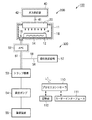
図1は、本発明の第1の実施形態に係る排気系構造を備えた成膜装置を示す模式図である。この成膜装置100は、成膜処理部200と、排気系300とに大別される。
First, the first embodiment will be described.
FIG. 1 is a schematic view showing a film forming apparatus having an exhaust system structure according to the first embodiment of the present invention. The
成膜処理部200は略円筒状の処理チャンバ11を有している。処理チャンバ11内の底部には、被処理基板であるウエハWを水平に載置するための載置台12が配置されている。載置台12にはヒータ14が埋め込まれており、このヒータ14は被処理基板であるウエハWを所定の温度に加熱する。処理チャンバ11の底壁には、排気口16が設けられている。また、処理チャンバ11の側壁にはゲートバルブにより開閉可能なウエハ搬入出口(図示せず)が設けられている。
The
処理チャンバ11の上部には、ガス導入部であるシャワーヘッド20が設けられている。このシャワーヘッド20は円盤状をなし下部に多数のガス吐出孔が形成されている。
A
上記シャワーヘッド20には、配管41を介して成膜のための原料ガスおよび還元ガス等を供給するガス供給部40が接続されている。
The
ガス供給部40は、有機金属原料ガスである有機Cu化合物ガスおよび有機Mn化合物ガスと、還元ガスであるH2ガスをシャワーヘッド20へ供給する。Cu原料である有機Cu化合物およびMn原料である有機Mn化合物は液体状または固体状をなしており、固体状のものは溶媒に溶解した状態で用いられる。また、液体状のものはそのまま用いることもできるが、粘性を下げて気化性および取り扱い性を向上させる観点から、溶媒に溶解した状態で用いることが好ましい。このような液体状の原料を、気化器等の適宜の手段により気化してシャワーヘッド20に導入する。なお、シャワーヘッド20への配管は便宜上1本のみ描いているが、実際には原料ガスと還元ガスとが別個の配管でシャワーヘッド20へ導入される。シャワーヘッド20は、原料ガスと還元ガスとが別個の経路を通って吐出され、吐出後にこれらが混合される、いわゆるポストミックスタイプとなっている。
The
一方、排気系300は、上記排気口16に接続された排気管51を有している。この排気管51には、上流側から順に、自動圧力制御器(APC)52、トラップ機構53、真空ポンプ54、除害装置55が設けられている。また、自動圧力制御器(APC)52とトラップ機構53との間には、配管56が接続されており、配管56の他端には酸化剤供給部57が接続されている。
On the other hand, the
処理チャンバ11内は、真空ポンプ54により配管51を介して真空排気されるようになっており、その際の処理チャンバ11内の圧力は、自動圧力制御器(APC)52により制御される。自動圧力制御器(APC)52は、処理チャンバ11内の圧力を図示しない圧力計によりモニタし、その圧力が所定の値になるように、バルブの開度を調節して配管51の排気量を調整するものである。
The inside of the
酸化剤供給部57は、酸化剤として例えばH2Oを供給するものであり、排気管51を流れている排ガスに配管56を介してH2Oが供給される。排ガスは、未反応の有機金属原料ガス成分および副生成物を含んでおり、これらが酸化剤であるH2Oと反応して酸化物系の生成物が生成される。H2Oの供給方式は、バブリング式、加熱蒸発式、液体気化式、液体霧化式、超音波式等、公知の気体供給方式を用いることができる。
Oxidant supplier 57 is configured to supply, for example, H 2 O as the oxidizing agent, H 2 O is supplied via a
トラップ機構53は、排ガスに酸化剤が供給されて形成された酸化物系の生成物をトラップするもので、このような生成物は通常は粉体状であるので、トラップ機構53としては粉体回収トラップが用いられる。このような粉体回収トラップとしては、冷却トラップ、さえぎりトラップ、フィルタトラップ、サイクロントラップ、静電トラップ、重力トラップ、慣性トラップ等、従来公知のトラップ機構を用いることが可能である。 The trap mechanism 53 traps an oxide-based product formed by supplying an oxidant to exhaust gas. Since such a product is usually in a powder form, the trap mechanism 53 is a powder. A recovery trap is used. As such a powder recovery trap, a conventionally known trap mechanism such as a cooling trap, a shield trap, a filter trap, a cyclone trap, an electrostatic trap, a gravity trap, or an inertia trap can be used.
真空ポンプ54としてはドライポンプを用いることができる。より高真空を要求される場合には、ドライポンプの他に、自動圧力制御器(APC)52の下流側であって、酸化剤を供給する配管56との合流点より上流側ににターボ分子ポンプ(TMP)を設置してもよい。
As the
除害装置55は、トラップ機構53で生成物をトラップした後の排ガス中の残余の有害成分を無害化するものであり、加熱触媒式、燃焼式、吸着式、プラズマ反応式等、従来公知の方式のものを採用することができる。
The
なお、ガス供給部40の配管等はヒータ42より加熱され、処理チャンバ11およびシャワーヘッド20はヒータ18により加熱され、排気管51のトラップ機構53の直前までの部分、自動圧力制御器(APC)52、配管56は、ヒータ58で加熱されるようになっており、これらの加熱により、トラップ機構53に至るまでの有機金属原料ガスの凝集を防止するようになっている。
The piping of the
成膜装置100の各構成部は、マイクロプロセッサ(コンピュータ)を備えたプロセスコントローラ110に接続されて制御される構成となっている。プロセスコントローラ110には、オペレータが成膜装置100を管理するためにコマンドの入力操作等を行うキーボードや、成膜装置100の稼働状況を可視化して表示するディスプレイ等からなるユーザーインターフェース111と、成膜装置100で実行される各種処理をプロセスコントローラ110の制御にて実現するための制御プログラムや、処理条件に応じて成膜装置100の各構成部に処理を実行させるためのプログラムすなわちレシピが格納された記憶部112が接続されている。レシピは記憶部112の中の記憶媒体に記憶されている。記憶媒体は、ハードディスクのように固定的なものであってもよいし、CDROM、DVD、フラッシュメモリ等の可搬性のものであってもよい。また、他の装置から、例えば専用回線を介してレシピを適宜伝送させるようにしてもよい。
Each component of the
そして、必要に応じて、ユーザーインターフェース111からの指示等にて任意のレシピを記憶部112から呼び出してプロセスコントローラ110に実行させることで、プロセスコントローラ110の制御下で、成膜装置100での所望の処理が行われる。
Then, if necessary, an arbitrary recipe is called from the
特に、本実施形態では成膜装置100の排気系300における排気処理が記憶部112に記憶された排気処理レシピに基づいてプロセスコントローラ110により制御される。
In particular, in the present embodiment, the exhaust processing in the
次に、以上のように構成された成膜装置100の処理動作について説明する。
まず、排気系300の真空ポンプ54を作動させて処理チャンバ11内を真空引きし、自動圧力制御器(APC)52により処理チャンバ11内を所定の圧力に保持しつつウエハWを真空雰囲気のままチャンバ11内に搬入し、サセプタ12上に載置する。
Next, the processing operation of the
First, the
この状態で、ガス供給部40から所定の流量で、有機金属原料である有機Cu化合物ガスおよび有機Mn化合物ガスをシャワーヘッド20を介して処理チャンバ11内に導入するとともに、還元ガスとしてH2ガスをシャワーヘッド20を介して処理チャンバ11内に導入して、ヒータ14により例えば100〜450℃の範囲の温度までウエハWを加熱する。これにより、ウエハW上で有機Cu化合物ガスおよび有機Mn化合物ガスと還元ガスであるH2ガスとが反応してウエハW上にCuMn膜が成膜される。
In this state, an organic Cu compound gas and an organic Mn compound gas, which are organic metal raw materials, are introduced into the
この成膜処理の間、処理チャンバ11から排ガスが排気管51を通って排出されるが、このような有機金属原料ガスを用いた場合には、有機金属原料ガスの全てが反応に寄与するわけではなく、成膜に寄与しなかった有機金属原料ガスや反応副生成物が大量に発生する。これら有機金属原料ガスや反応副生成物は、活性が高い。特に、ここで用いている有機Mn化合物ガスは、極めて活性が高く、H2Oのような酸化剤により急激に反応するため、「禁水」扱いとされている。
During this film forming process, exhaust gas is exhausted from the
すなわち、有機金属原料ガス、特に有機Mn化合物ガスは、従来のようにトラップ機構に単に物理的に吸着させた場合には、極めて高い活性を保ったままであるため、トラップ機構を大気開放する際に急激に反応が生じるおそれがあるため、極めて危険であり、このような危険を回避するためには、トラップ機構の処理に極めて手間がかかってしまう。 That is, when the trapping mechanism is opened to the atmosphere, the organometallic source gas, particularly the organic Mn compound gas, remains in a very high activity when it is simply physically adsorbed to the trap mechanism as in the prior art. Since there is a possibility of a reaction occurring suddenly, it is extremely dangerous, and in order to avoid such a danger, it takes much time to process the trap mechanism.
そこで、本実施形態では、排気管51の自動圧力制御器(APC)52の下流側に、酸化剤供給部57から配管56を介して酸化剤としてH2Oを供給する。これにより、上述したような大気開放した際に生じる酸化反応が排気管51内で緩やかに生じ、排気管51内で酸化物系の生成物が生成される。したがって、トラップ機構53にはこのような酸化物系の生成物がトラップされ回収される。このとき、酸化剤としてのH2Oが自動圧力制御器(APC)52の下流側であるため、成膜プロセスには影響を与えない。
Therefore, in this embodiment, H 2 O is supplied as an oxidant from the oxidant supply unit 57 via the
このようにして生成される酸化物系の生成物は失活した状態であるため、トラップ機構53を大気開放しても急激な反応は生じず安全であり、かつ、トラップ機構53の回収物の処理を迅速に行うことができる。また、トラップ機構53で回収された回収物は失活されているので、除害装置55への負担が軽くなってその寿命が延び、メンテナンス工数および費用を低減することができる。
Since the oxide-based product generated in this manner is in an inactivated state, even if the trap mechanism 53 is opened to the atmosphere, a rapid reaction does not occur and it is safe, and the collected product of the trap mechanism 53 Processing can be performed quickly. Further, since the collected material collected by the trap mechanism 53 is deactivated, the burden on the
このような酸化剤としてのH2Oによる失活処理は、特にH2Oとの反応性の極めて高い有機Mn化合物に対して有効であるが、もちろん有機Cu化合物もH2Oと反応するので有機Mn化合物ほどではないがある程度の効果は得られる。 Such deactivation treatment with H 2 O as an oxidizing agent is particularly effective for organic Mn compounds that are extremely reactive with H 2 O, but of course, organic Cu compounds also react with H 2 O. Although not as good as organic Mn compounds, some effects can be obtained.
本実施形態に好適な有機Mn化合物としては、(EtCp)2Mn、(MeCp)2Mn、(i−PrCp)2Mn、Cp2Mn、(MeCp)Mn(CO)3等を挙げることができる。また、本実施形態に用いることができる有機Cu化合物としては、Cu(hfac)TMVS等を挙げることができる。 Examples of organic Mn compounds suitable for the present embodiment include (EtCp) 2 Mn, (MeCp) 2 Mn, (i-PrCp) 2 Mn, Cp 2 Mn, (MeCp) Mn (CO) 3 and the like. . Moreover, Cu (hfac) TMVS etc. can be mentioned as an organic Cu compound which can be used for this embodiment.
有機Mn化合物とH2Oとの反応は、例えば、有機Mn化合物が
(EtCp)2Mnの場合には、以下の(1)式に示すようなものであり、その中のMnが酸化されてMnOまたはMnO2となり、有機骨格部分であるEtCpは、Hと結合してEtCpHや(EtCpH)2となって下流に流れて行き除害装置55において無害化される。
(EtCp)2Mn+H2O→2EtCpH+MnO……(1)
For example, when the organic Mn compound is (EtCp) 2 Mn, the reaction between the organic Mn compound and H 2 O is as shown in the following formula (1), in which Mn is oxidized. EtCp which is MnO or MnO 2 and is an organic skeleton portion is combined with H to become EtCpH or (EtCpH) 2 and flows downstream to be detoxified in the
(EtCp) 2 Mn + H 2 O → 2 EtCpH + MnO (1)
次に、第2の実施形態について説明する。
図2は、本発明の第2の実施形態に係る排気系構造を備えた成膜装置を示す模式図である。この第2の実施形態では真空ポンプ54の配置位置が第1の実施形態とは異なり、酸化剤であるH2Oの供給位置とトラップ機構53との間にある。このため、酸化剤供給部57から配管56を介して排気管51にH2Oが供給された後、真空ポンプ54を経てからトラップ機構53に達するので、排気ガスと酸化剤であるH2Oが真空ポンプ54でしっかり混ざって完全に反応した後にトラップ機構53に回収される。この点、上記第1の実施形態では、排気管51へのH2O供給位置の圧力が低く、かつH2Oと排ガスが排気管51に合流してすぐにトラップ機構53にトラップされるため、排ガス成分とH2Oとの反応がやや進行しにくい。したがって、反応性の観点からは第2の実施形態のほうが好ましい。
Next, a second embodiment will be described.
FIG. 2 is a schematic view showing a film forming apparatus having an exhaust system structure according to the second embodiment of the present invention. In the second embodiment, the arrangement position of the
ただし、第2の実施形態では、排ガスがトラップ機構53に至る前に真空ポンプ54を通過するため、排ガス中の原料ガスの凝集を防止するための加熱を真空ポンプ54にも施す必要があり、図示するように、ヒータ58を真空ポンプ54にも設けなければならない。また、真空ポンプ54で排ガスとH2Oとを混合し酸化物系の生成物が生成されるので、真空ポンプ54の負担が重くなるという問題もある。これに対し、第1の実施形態では、真空ポンプ54への負担は軽く、加熱する必要もない。
However, in the second embodiment, since the exhaust gas passes through the
次に、第3の実施形態について説明する。
図3は、本発明の第3の実施形態に係る排気系構造を備えた成膜装置を示す模式図である。この第3の実施形態では真空ポンプ54の配置位置が第1および第2の実施形態とは異なり、自動圧力制御器(APC)52と酸化剤であるH2Oの供給位置との間にある。このため、真空ポンプ54を経てから排ガスにH2Oが供給されることとなるので、高圧にて排ガスとH2Oとの反応が生じることとなり、反応が進みやすくなる。また、H2Oは真空ポンプ54を通らないため、真空ポンプ54内で酸化物系の生成物が生じることはなく真空ポンプ54への負担は軽い。ただし、第2の実施形態と同様、排ガスがトラップ機構53に至る前に真空ポンプ54を通過するため、排ガス中の原料ガスの凝集を防止するための加熱を真空ポンプ54にも施す必要があり、図示するように、ヒータ58を真空ポンプ54にも設けなければならない。
Next, a third embodiment will be described.
FIG. 3 is a schematic view showing a film forming apparatus having an exhaust system structure according to the third embodiment of the present invention. In the third embodiment, the arrangement position of the
以上の第1〜第3の実施形態は、それぞれ一長一短があり、状況に応じて使い分けることが好ましい。 Each of the first to third embodiments described above has advantages and disadvantages, and it is preferable to use them according to the situation.
なお、本発明は上記実施形態に限定されることなく種々変形可能である。例えば、上記実施形態では、酸化剤としてH2Oを用いた例を示したが、これに限定されることなく、O3、O2、H2O2、NO2、N2Oやアルコール類、有機溶媒、有機酸、空気等、その成分中に酸素が含まれるものであれば適用可能である。また酸化剤として酸素が含まれるもの以外に、Cl2などのハロゲンが含まれるものも適用可能である。ただしCuMn膜を成膜する際に、還元ガスとしてH2を用いる場合には、これと混合禁忌となる酸化剤は使用しないようにする。 The present invention can be variously modified without being limited to the above embodiment. For example, in the above embodiment, an example using H 2 O as the oxidizing agent, it is not limited thereto, O 3, O 2, H 2 O 2, NO 2, N 2 O or alcohol Any organic solvent, organic acid, air, or the like containing oxygen in its components is applicable. In addition to oxygen containing oxygen as an oxidizing agent, those containing halogen such as Cl 2 are also applicable. However when depositing CuMn film, when H 2 is used as the reducing gas, the oxidizing agent to be this mixed contraindication to avoid using.
また、上記実施形態では、有機金属原料として有機Mn化合物および有機Cu化合物を、特に有機Mn化合物を例にとって説明したが、これに限らず、酸化剤と反応するものであれば適用可能であり、例えばAl,Ti,Fe,Co,Ni,Zn,Zr,Ru,Hf,Ta,W等の他の金属の有機化合物を適用することができる。 Moreover, in the said embodiment, although organic Mn compound and organic Cu compound were demonstrated as an example of the organic metal raw material, especially the organic Mn compound was used as an example, it is not limited to this, and can be applied as long as it reacts with an oxidizing agent. For example, organic compounds of other metals such as Al, Ti, Fe, Co, Ni, Zn, Zr, Ru, Hf, Ta, and W can be applied.
また、上記実施形態では、被処理基板として半導体ウエハを例示したが、これに限らず、液晶表示装置(LCD)に代表されるフラットパネルディスプレー(FPD)用のガラス基板等、他の基板にも適用可能である。 Moreover, in the said embodiment, although the semiconductor wafer was illustrated as a to-be-processed substrate, it is not restricted to this, Other substrates, such as a glass substrate for flat panel displays (FPD) represented by the liquid crystal display device (LCD), are also shown. Applicable.
さらに、上記実施形態では、成膜装置として枚葉式のものを例にとって説明したが、これに限らず、多数の被処理基板を一度に処理するバッチ式のものであっても適用可能である。 Furthermore, in the above-described embodiment, the single-wafer type film forming apparatus has been described as an example. However, the present invention is not limited to this, and a batch type apparatus that processes a large number of substrates to be processed at one time is also applicable. .
11;処理チャンバ
12;載置台
14;ヒータ
16;排気口
20;シャワーヘッド
40;ガス供給部
41;配管
51;排気管
52;自動圧力制御器(APC)
53;トラップ機構
54;真空ポンプ
55;除害装置
56;配管
57;酸化剤供給部
100;成膜装置
200;成膜処理部
300;排気系
W;半導体ウエハ
DESCRIPTION OF
53;
Claims (10)
前記処理容器内の排ガスを排出する排気管と、
前記排気管の前記処理容器の近傍に設けられた自動圧力制御器と、
前記排気管の前記自動圧力制御器の下流側に設けられ、前記処理容器内を排気する真空ポンプと、
前記排気管の前記自動圧力制御器の下流側位置に、排ガス中の有機Mn化合物ガス成分および副生成物を酸化させるための水を酸化剤として供給する酸化剤供給部と、
前記排気管の前記酸化剤供給位置の下流側に設けられ、前記排ガス中の有機Mn化合物ガス成分および副生成物が前記酸化剤としての水と反応して生成された生成物を回収するトラップ機構と、
前記排気管の前記トラップ機構の下流側に設けられ、排ガスを無害化するための除害装置と
を具備することを特徴とする、成膜装置の排気系構造。 An exhaust system structure of a film forming apparatus for forming a film containing Mn by CVD on a substrate disposed in the processing container by supplying a gas containing a water-free organic Mn compound gas into the processing container,
An exhaust pipe for exhausting exhaust gas in the processing vessel;
An automatic pressure controller provided in the vicinity of the processing vessel of the exhaust pipe;
A vacuum pump that is provided downstream of the automatic pressure controller of the exhaust pipe and exhausts the inside of the processing vessel;
An oxidant supply unit that supplies , as an oxidant , water for oxidizing the organic Mn compound gas component and the by-product in the exhaust gas to the downstream position of the automatic pressure controller of the exhaust pipe;
A trap mechanism that is provided on the downstream side of the oxidant supply position of the exhaust pipe and collects the product produced by the reaction of the organic Mn compound gas component and by-product in the exhaust gas with water as the oxidant When,
An exhaust system structure for a film forming apparatus, comprising: a detoxification device provided on a downstream side of the trap mechanism of the exhaust pipe and detoxifying exhaust gas.
基板が配置された処理容器内に禁水扱いの有機Mn化合物ガスを含むガスを供給する原料ガス供給機構と、
前記有機Mn化合物ガスにエネルギーを与えて基板上で成膜反応を生じさせる手段と、
前記処理容器から排ガスを排出させ、排ガスを処理する排気系構造と
を具備し、
基板上にMnを含む膜を形成する成膜装置であって、
前記排気系構造は、
前記処理容器内の排ガスを排出する排気管と、
前記排気管の前記処理容器の近傍に設けられた自動圧力制御器と、
前記排気管の前記自動圧力制御器の下流側に設けられ、前記処理容器内を排気する真空ポンプと、
前記排気管の前記自動圧力制御器の下流側位置に、排ガス中の有機Mn化合物ガス成分および副生成物を酸化させるための水を酸化剤として供給する酸化剤供給部と、
前記排気管の前記酸化剤供給位置の下流側に設けられ、前記排ガス中の有機Mn化合物ガス成分および副生成物が前記酸化剤としての水と反応して生成された生成物を回収するトラップ機構と、
前記排気管の前記トラップ機構の下流側に設けられ、排ガスを無害化するための除害装置と
を具備することを特徴とする、成膜装置。 A processing vessel in which a substrate is placed;
A raw material gas supply mechanism for supplying a gas containing a water-free organic Mn compound gas into a processing vessel in which a substrate is disposed;
Means for applying energy to the organic Mn compound gas to cause a film forming reaction on the substrate;
Exhaust gas is discharged from the processing container, and an exhaust system structure for processing the exhaust gas is provided.
A film forming apparatus for forming a film containing Mn on a substrate,
The exhaust system structure is
An exhaust pipe for exhausting exhaust gas in the processing vessel;
An automatic pressure controller provided in the vicinity of the processing vessel of the exhaust pipe;
A vacuum pump that is provided downstream of the automatic pressure controller of the exhaust pipe and exhausts the inside of the processing vessel;
An oxidant supply unit that supplies , as an oxidant , water for oxidizing the organic Mn compound gas component and the by-product in the exhaust gas to the downstream position of the automatic pressure controller of the exhaust pipe;
A trap mechanism that is provided on the downstream side of the oxidant supply position of the exhaust pipe and collects the product produced by the reaction of the organic Mn compound gas component and by-product in the exhaust gas with water as the oxidant When,
A film forming apparatus, comprising: a detoxification device provided on the downstream side of the trap mechanism of the exhaust pipe and detoxifying the exhaust gas.
前記処理容器に接続された排気管を介して真空ポンプにより処理容器内を排気し、
前記排気管の自動圧力制御器の下流側で成膜処理の際の排ガスに酸化剤としての水を供給して排ガス中の有機Mn化合物ガス成分および副生成物を酸化させ、
前記排ガス中の有機Mn化合物ガス成分および副生成物が前記酸化剤としての水と反応して生成された生成物をトラップ機構により回収し、
生成物が回収された後の排ガスを除害装置により処理することを特徴とする、排ガスの処理方法。 A method for treating exhaust gas in a film forming apparatus for forming a film containing Mn by CVD on a substrate disposed in a processing container by supplying a gas containing water-free organic Mn compound gas into the processing container,
Exhaust the inside of the processing container by a vacuum pump through an exhaust pipe connected to the processing container,
Supplying water as an oxidant to the exhaust gas during the film forming process downstream of the automatic pressure controller of the exhaust pipe to oxidize organic Mn compound gas components and by-products in the exhaust gas ,
The organic Mn compound gas component and the by-product in the exhaust gas react with water as the oxidant to collect a product generated by a trap mechanism,
An exhaust gas treatment method, wherein the exhaust gas after the product is collected is treated by a detoxifying device.
Priority Applications (6)
| Application Number | Priority Date | Filing Date | Title |
|---|---|---|---|
| JP2007233533A JP5133013B2 (en) | 2007-09-10 | 2007-09-10 | Exhaust system structure of film forming apparatus, film forming apparatus, and exhaust gas treatment method |
| PCT/JP2008/065661 WO2009034865A1 (en) | 2007-09-10 | 2008-09-01 | Exhaust system structure of film forming apparatus, film forming apparatus and method of disposing of exhaust gas |
| CN200880106461XA CN101802256B (en) | 2007-09-10 | 2008-09-01 | Exhaust system structure of film forming apparatus, film forming apparatus and method of disposing of exhaust gas |
| US12/677,417 US20110020544A1 (en) | 2007-09-10 | 2008-09-01 | Exhaust system structure of film formation apparatus, film formation apparatus, and exhaust gas processing method |
| KR1020107005256A KR101151513B1 (en) | 2007-09-10 | 2008-09-01 | Exhaust system structure of film forming apparatus, film forming apparatus and method of disposing of exhaust gas |
| KR1020127003984A KR101209997B1 (en) | 2007-09-10 | 2008-09-01 | Exhaust system structure of film forming apparatus, film forming apparatus and method of disposing of exhaust gas |
Applications Claiming Priority (1)
| Application Number | Priority Date | Filing Date | Title |
|---|---|---|---|
| JP2007233533A JP5133013B2 (en) | 2007-09-10 | 2007-09-10 | Exhaust system structure of film forming apparatus, film forming apparatus, and exhaust gas treatment method |
Publications (3)
| Publication Number | Publication Date |
|---|---|
| JP2009062599A JP2009062599A (en) | 2009-03-26 |
| JP2009062599A5 JP2009062599A5 (en) | 2010-07-01 |
| JP5133013B2 true JP5133013B2 (en) | 2013-01-30 |
Family
ID=40451874
Family Applications (1)
| Application Number | Title | Priority Date | Filing Date |
|---|---|---|---|
| JP2007233533A Expired - Fee Related JP5133013B2 (en) | 2007-09-10 | 2007-09-10 | Exhaust system structure of film forming apparatus, film forming apparatus, and exhaust gas treatment method |
Country Status (5)
| Country | Link |
|---|---|
| US (1) | US20110020544A1 (en) |
| JP (1) | JP5133013B2 (en) |
| KR (2) | KR101151513B1 (en) |
| CN (1) | CN101802256B (en) |
| WO (1) | WO2009034865A1 (en) |
Cited By (1)
| Publication number | Priority date | Publication date | Assignee | Title |
|---|---|---|---|---|
| US11738299B2 (en) | 2020-12-24 | 2023-08-29 | Samsung Electronics Co., Ltd. | Exhaust gas processing system including adsorbent for suppressing powder-like byproduct |
Families Citing this family (19)
| Publication number | Priority date | Publication date | Assignee | Title |
|---|---|---|---|---|
| US20090014423A1 (en) * | 2007-07-10 | 2009-01-15 | Xuegeng Li | Concentric flow-through plasma reactor and methods therefor |
| US8471170B2 (en) | 2007-07-10 | 2013-06-25 | Innovalight, Inc. | Methods and apparatus for the production of group IV nanoparticles in a flow-through plasma reactor |
| US8968438B2 (en) * | 2007-07-10 | 2015-03-03 | Innovalight, Inc. | Methods and apparatus for the in situ collection of nucleated particles |
| JP5277784B2 (en) * | 2008-08-07 | 2013-08-28 | 東京エレクトロン株式会社 | Raw material recovery method, trap mechanism, exhaust system, and film forming apparatus using the same |
| JP5696348B2 (en) * | 2008-08-09 | 2015-04-08 | 東京エレクトロン株式会社 | Metal recovery method, metal recovery apparatus, exhaust system, and film forming apparatus using the same |
| US20110195202A1 (en) * | 2010-02-11 | 2011-08-11 | Applied Materials, Inc. | Oxygen pump purge to prevent reactive powder explosion |
| JP2012117127A (en) * | 2010-12-02 | 2012-06-21 | Sumitomo Heavy Ind Ltd | Film deposition device, film deposition substrate manufacturing method, and film deposition substrate |
| US10954594B2 (en) * | 2015-09-30 | 2021-03-23 | Applied Materials, Inc. | High temperature vapor delivery system and method |
| JP6602709B2 (en) * | 2016-03-23 | 2019-11-06 | 大陽日酸株式会社 | Exhaust gas treatment apparatus and exhaust gas treatment method |
| JP6559618B2 (en) * | 2016-06-23 | 2019-08-14 | 株式会社Kokusai Electric | Semiconductor device manufacturing method, substrate processing apparatus, and program |
| JP6828674B2 (en) * | 2017-12-20 | 2021-02-10 | 株式会社Sumco | Cleaning method, silicon single crystal manufacturing method, and cleaning equipment |
| US11236021B2 (en) * | 2017-12-22 | 2022-02-01 | Goodrich Corporation | Mitigating pyrophoric deposits in exhaust piping during SIC CVI/CVD processes by introducing water vapor into an outlet portion of a reaction chamber |
| KR102078584B1 (en) * | 2017-12-28 | 2020-02-19 | (주) 엔피홀딩스 | Exhaust fluid treatment apparatus and substrate treatment system |
| KR102054411B1 (en) * | 2017-12-28 | 2019-12-10 | (주) 엔피홀딩스 | Exhaust fluid treatment apparatus and substrate treatment system |
| JP7175782B2 (en) * | 2019-01-25 | 2022-11-21 | 株式会社東芝 | Silicon-containing material forming device |
| JP6900412B2 (en) * | 2019-03-20 | 2021-07-07 | 株式会社Kokusai Electric | Manufacturing methods and programs for substrate processing equipment and semiconductor equipment |
| CN111013303A (en) * | 2019-12-09 | 2020-04-17 | 木昇半导体科技(苏州)有限公司 | Gallium nitride particle recycling and cleaning vacuum system |
| KR102250066B1 (en) * | 2020-02-17 | 2021-05-10 | 김홍석 | Reduce to POWDER GENERATIONDEVICE inside Vacuum line of PROCES CHAMBER OF SEMICONDUCTOR AND FPD |
| WO2024039512A1 (en) * | 2022-08-16 | 2024-02-22 | Kulicke And Soffa Industries, Inc. | Bonding systems for bonding a semiconductor element to a substrate, and related methods |
Family Cites Families (46)
| Publication number | Priority date | Publication date | Assignee | Title |
|---|---|---|---|---|
| US4940213A (en) * | 1987-08-24 | 1990-07-10 | Kabushiki Kaisha Toshiba | Exhaust processing apparatus |
| TW241375B (en) * | 1993-07-26 | 1995-02-21 | Air Prod & Chem | |
| JP3287730B2 (en) * | 1995-04-20 | 2002-06-04 | 東京エレクトロン株式会社 | Apparatus for removing contaminants, vacuum evacuation system of processing apparatus using the same, and maintenance method thereof |
| JPH09232296A (en) * | 1996-02-23 | 1997-09-05 | Mitsubishi Electric Corp | Apparatus and method for manufacture of semiconductor device |
| US5895530A (en) * | 1996-02-26 | 1999-04-20 | Applied Materials, Inc. | Method and apparatus for directing fluid through a semiconductor processing chamber |
| JP3544604B2 (en) * | 1996-12-16 | 2004-07-21 | 株式会社荏原製作所 | Switchable trap device |
| US5993916A (en) * | 1996-07-12 | 1999-11-30 | Applied Materials, Inc. | Method for substrate processing with improved throughput and yield |
| US5928426A (en) * | 1996-08-08 | 1999-07-27 | Novellus Systems, Inc. | Method and apparatus for treating exhaust gases from CVD, PECVD or plasma etch reactors |
| US5827370A (en) * | 1997-01-13 | 1998-10-27 | Mks Instruments, Inc. | Method and apparatus for reducing build-up of material on inner surface of tube downstream from a reaction furnace |
| US6673673B1 (en) * | 1997-04-22 | 2004-01-06 | Samsung Electronics Co., Ltd. | Method for manufacturing a semiconductor device having hemispherical grains |
| US6149729A (en) * | 1997-05-22 | 2000-11-21 | Tokyo Electron Limited | Film forming apparatus and method |
| US6099649A (en) * | 1997-12-23 | 2000-08-08 | Applied Materials, Inc. | Chemical vapor deposition hot-trap for unreacted precursor conversion and effluent removal |
| JP3567070B2 (en) * | 1997-12-27 | 2004-09-15 | 東京エレクトロン株式会社 | Heat treatment apparatus and heat treatment method |
| US20030101938A1 (en) * | 1998-10-27 | 2003-06-05 | Applied Materials, Inc. | Apparatus for the deposition of high dielectric constant films |
| US6383300B1 (en) * | 1998-11-27 | 2002-05-07 | Tokyo Electron Ltd. | Heat treatment apparatus and cleaning method of the same |
| US6238514B1 (en) * | 1999-02-18 | 2001-05-29 | Mks Instruments, Inc. | Apparatus and method for removing condensable aluminum vapor from aluminum etch effluent |
| JP2000256856A (en) * | 1999-03-11 | 2000-09-19 | Tokyo Electron Ltd | Treating device, vacuum exhaust system for treating device, vacuum cvd device, vacuum exhaust system for vacuum cvd device and trapping device |
| JP4487338B2 (en) * | 1999-08-31 | 2010-06-23 | 東京エレクトロン株式会社 | Film forming apparatus and film forming method |
| US6500487B1 (en) * | 1999-10-18 | 2002-12-31 | Advanced Technology Materials, Inc | Abatement of effluent from chemical vapor deposition processes using ligand exchange resistant metal-organic precursor solutions |
| JP4599701B2 (en) * | 1999-11-24 | 2010-12-15 | 東京エレクトロン株式会社 | Exhaust system structure of film forming apparatus and impurity gas removal method |
| US6773687B1 (en) * | 1999-11-24 | 2004-08-10 | Tokyo Electron Limited | Exhaust apparatus for process apparatus and method of removing impurity gas |
| JP4162366B2 (en) * | 2000-03-31 | 2008-10-08 | 田中貴金属工業株式会社 | CVD thin film forming process and CVD thin film manufacturing apparatus |
| JP2001293332A (en) * | 2000-04-11 | 2001-10-23 | Nippon Sanso Corp | Method and device for treatment and recovery of cvd waste gas |
| US6800254B1 (en) * | 2000-06-07 | 2004-10-05 | Tegal Corporation | Visual indicator cold trapping system |
| US6998097B1 (en) * | 2000-06-07 | 2006-02-14 | Tegal Corporation | High pressure chemical vapor trapping system |
| JP2002025909A (en) * | 2000-06-30 | 2002-01-25 | Sony Corp | Device for removal of hazard in film formation apparatus and removal method therefor |
| US6844273B2 (en) * | 2001-02-07 | 2005-01-18 | Tokyo Electron Limited | Precleaning method of precleaning a silicon nitride film forming system |
| FR2825295B1 (en) * | 2001-05-31 | 2004-05-28 | Air Liquide | APPLICATION OF DENSITY PLASMAS CREATED AT ATMOSPHERIC PRESSURE FOR THE TREATMENT OF GASEOUS EFFLUENTS |
| US7060234B2 (en) * | 2001-07-18 | 2006-06-13 | Applied Materials | Process and apparatus for abatement of by products generated from deposition processes and cleaning of deposition chambers |
| US6528420B1 (en) * | 2002-01-18 | 2003-03-04 | Chartered Semiconductor Manufacturing Ltd. | Double acting cold trap |
| JP4074461B2 (en) * | 2002-02-06 | 2008-04-09 | 東京エレクトロン株式会社 | Film forming method, film forming apparatus, and semiconductor device manufacturing method |
| JP2003245520A (en) * | 2002-02-26 | 2003-09-02 | Seiko Epson Corp | Pfc decomposition method, pfc decomposition apparatus and method for manufacturing semiconductor device |
| KR100505670B1 (en) * | 2003-02-05 | 2005-08-03 | 삼성전자주식회사 | Apparatus for manufacturing semiconductor device having hot fluid supplier for removing byproducts |
| WO2005064649A2 (en) * | 2003-12-23 | 2005-07-14 | Schumacher John C | Exhaust conditioning system for semiconductor reactor |
| JP2005340283A (en) * | 2004-05-24 | 2005-12-08 | Hitachi Kokusai Electric Inc | Substrate treatment |
| US20060021571A1 (en) * | 2004-07-28 | 2006-02-02 | Taiwan Semiconductor Manufacturing Co., Ltd. | Vacuum pump line with nickel-chromium heater layer |
| TWI279260B (en) * | 2004-10-12 | 2007-04-21 | Applied Materials Inc | Endpoint detector and particle monitor |
| JP4236201B2 (en) * | 2005-08-30 | 2009-03-11 | 富士通マイクロエレクトロニクス株式会社 | Manufacturing method of semiconductor device |
| JP5036354B2 (en) * | 2006-04-04 | 2012-09-26 | 東京エレクトロン株式会社 | Exhaust system structure of film forming apparatus, film forming apparatus, and exhaust gas treatment method |
| JP2009016782A (en) * | 2007-06-04 | 2009-01-22 | Tokyo Electron Ltd | Film forming method, and film forming apparatus |
| JPWO2009038168A1 (en) * | 2007-09-21 | 2011-01-06 | 東京エレクトロン株式会社 | Film forming apparatus and film forming method |
| JP5366235B2 (en) * | 2008-01-28 | 2013-12-11 | 東京エレクトロン株式会社 | Semiconductor device manufacturing method, semiconductor manufacturing apparatus, and storage medium |
| JP5417754B2 (en) * | 2008-07-11 | 2014-02-19 | 東京エレクトロン株式会社 | Film forming method and processing system |
| JP2010212492A (en) * | 2009-03-11 | 2010-09-24 | Tokyo Electron Ltd | Method of manufacturing semiconductor device |
| US8531033B2 (en) * | 2009-09-07 | 2013-09-10 | Advanced Interconnect Materials, Llc | Contact plug structure, semiconductor device, and method for forming contact plug |
| US9029264B2 (en) * | 2012-03-14 | 2015-05-12 | Applied Materials, Inc. | Methods for depositing a tin-containing layer on a substrate |
-
2007
- 2007-09-10 JP JP2007233533A patent/JP5133013B2/en not_active Expired - Fee Related
-
2008
- 2008-09-01 CN CN200880106461XA patent/CN101802256B/en not_active Expired - Fee Related
- 2008-09-01 KR KR1020107005256A patent/KR101151513B1/en not_active IP Right Cessation
- 2008-09-01 US US12/677,417 patent/US20110020544A1/en not_active Abandoned
- 2008-09-01 KR KR1020127003984A patent/KR101209997B1/en not_active IP Right Cessation
- 2008-09-01 WO PCT/JP2008/065661 patent/WO2009034865A1/en active Application Filing
Cited By (1)
| Publication number | Priority date | Publication date | Assignee | Title |
|---|---|---|---|---|
| US11738299B2 (en) | 2020-12-24 | 2023-08-29 | Samsung Electronics Co., Ltd. | Exhaust gas processing system including adsorbent for suppressing powder-like byproduct |
Also Published As
| Publication number | Publication date |
|---|---|
| WO2009034865A1 (en) | 2009-03-19 |
| KR101151513B1 (en) | 2012-05-31 |
| CN101802256B (en) | 2012-06-06 |
| CN101802256A (en) | 2010-08-11 |
| KR20120034234A (en) | 2012-04-10 |
| US20110020544A1 (en) | 2011-01-27 |
| KR20100053639A (en) | 2010-05-20 |
| JP2009062599A (en) | 2009-03-26 |
| KR101209997B1 (en) | 2012-12-07 |
Similar Documents
| Publication | Publication Date | Title |
|---|---|---|
| JP5133013B2 (en) | Exhaust system structure of film forming apparatus, film forming apparatus, and exhaust gas treatment method | |
| TWI646212B (en) | High growth rate process for conformal aluminum nitride | |
| JP5514129B2 (en) | Film forming method, film forming apparatus, and method of using film forming apparatus | |
| JP5720406B2 (en) | GAS SUPPLY DEVICE, HEAT TREATMENT DEVICE, GAS SUPPLY METHOD, AND HEAT TREATMENT METHOD | |
| JP5258229B2 (en) | Film forming method and film forming apparatus | |
| JP5250600B2 (en) | Film forming method and film forming apparatus | |
| US20120031334A1 (en) | Gas exhaust system of film-forming apparatus, film-forming apparatus, and method for processing exhaust gas | |
| WO2007088940A1 (en) | Pressure reducing apparatus | |
| WO2011033903A1 (en) | Method for formation of metal silicide film | |
| JP5221089B2 (en) | Film forming method, film forming apparatus, and storage medium | |
| WO2011033918A1 (en) | Film forming device, film forming method and storage medium | |
| JP5839514B2 (en) | Film forming method, film forming apparatus, and method of using film forming apparatus | |
| JP2009267345A (en) | Substrate processing apparatus | |
| JP5761067B2 (en) | Gas supply device and heat treatment device | |
| JP2008235313A (en) | Deposition material, method and device | |
| WO2010103879A1 (en) | METHOD FOR FORMING Cu FILM, AND STORAGE MEDIUM | |
| JP4979965B2 (en) | Substrate processing apparatus and semiconductor device manufacturing method | |
| JP2023529359A (en) | In-feature wet etch rate ratio reduction | |
| JP5145052B2 (en) | Film forming method, film forming apparatus, and storage medium | |
| JP2013199673A (en) | Method for forming ruthenium oxide film and method for cleaning treatment container for forming ruthenium oxide film | |
| JP5281856B2 (en) | Film forming method, film forming apparatus, and storage medium | |
| JP2007227804A (en) | Manufacturing method of semiconductor device | |
| WO2022220190A1 (en) | Surface treatment method and substrate treatment device | |
| JP4964097B2 (en) | Film forming method, film forming apparatus, and storage medium | |
| JP5659041B2 (en) | Film formation method and storage medium |
Legal Events
| Date | Code | Title | Description |
|---|---|---|---|
| A521 | Request for written amendment filed |
Free format text: JAPANESE INTERMEDIATE CODE: A523 Effective date: 20100517 |
|
| A621 | Written request for application examination |
Free format text: JAPANESE INTERMEDIATE CODE: A621 Effective date: 20100517 |
|
| TRDD | Decision of grant or rejection written | ||
| A01 | Written decision to grant a patent or to grant a registration (utility model) |
Free format text: JAPANESE INTERMEDIATE CODE: A01 Effective date: 20121016 |
|
| A01 | Written decision to grant a patent or to grant a registration (utility model) |
Free format text: JAPANESE INTERMEDIATE CODE: A01 |
|
| A61 | First payment of annual fees (during grant procedure) |
Free format text: JAPANESE INTERMEDIATE CODE: A61 Effective date: 20121107 |
|
| FPAY | Renewal fee payment (event date is renewal date of database) |
Free format text: PAYMENT UNTIL: 20151116 Year of fee payment: 3 |
|
| R150 | Certificate of patent or registration of utility model |
Free format text: JAPANESE INTERMEDIATE CODE: R150 |
|
| R250 | Receipt of annual fees |
Free format text: JAPANESE INTERMEDIATE CODE: R250 |
|
| LAPS | Cancellation because of no payment of annual fees |