JP5132050B2 - Specimen imaging apparatus, specimen imaging method, program for controlling the apparatus, and specimen analyzer - Google Patents
Specimen imaging apparatus, specimen imaging method, program for controlling the apparatus, and specimen analyzer Download PDFInfo
- Publication number
- JP5132050B2 JP5132050B2 JP2005287463A JP2005287463A JP5132050B2 JP 5132050 B2 JP5132050 B2 JP 5132050B2 JP 2005287463 A JP2005287463 A JP 2005287463A JP 2005287463 A JP2005287463 A JP 2005287463A JP 5132050 B2 JP5132050 B2 JP 5132050B2
- Authority
- JP
- Japan
- Prior art keywords
- specimen
- imaging
- related information
- sample
- information
- Prior art date
- Legal status (The legal status is an assumption and is not a legal conclusion. Google has not performed a legal analysis and makes no representation as to the accuracy of the status listed.)
- Active
Links
- 238000003384 imaging method Methods 0.000 title claims description 138
- 238000004458 analytical method Methods 0.000 claims description 22
- 238000004590 computer program Methods 0.000 claims 1
- 210000004369 blood Anatomy 0.000 description 68
- 239000008280 blood Substances 0.000 description 68
- 210000000601 blood cell Anatomy 0.000 description 33
- 210000004027 cell Anatomy 0.000 description 24
- 238000002360 preparation method Methods 0.000 description 22
- 230000032258 transport Effects 0.000 description 15
- 210000000265 leukocyte Anatomy 0.000 description 14
- 238000012545 processing Methods 0.000 description 14
- 238000012360 testing method Methods 0.000 description 10
- 238000000034 method Methods 0.000 description 8
- 230000002159 abnormal effect Effects 0.000 description 7
- 230000006870 function Effects 0.000 description 6
- 238000010191 image analysis Methods 0.000 description 5
- 238000004820 blood count Methods 0.000 description 4
- 238000000605 extraction Methods 0.000 description 4
- 238000003780 insertion Methods 0.000 description 4
- 230000037431 insertion Effects 0.000 description 4
- 239000000306 component Substances 0.000 description 3
- 238000001514 detection method Methods 0.000 description 3
- 230000005856 abnormality Effects 0.000 description 2
- 239000012503 blood component Substances 0.000 description 2
- 210000000805 cytoplasm Anatomy 0.000 description 2
- 238000010586 diagram Methods 0.000 description 2
- 210000004698 lymphocyte Anatomy 0.000 description 2
- 210000000440 neutrophil Anatomy 0.000 description 2
- 210000003924 normoblast Anatomy 0.000 description 2
- 238000010186 staining Methods 0.000 description 2
- 238000012546 transfer Methods 0.000 description 2
- 230000000007 visual effect Effects 0.000 description 2
- 102000001554 Hemoglobins Human genes 0.000 description 1
- 108010054147 Hemoglobins Proteins 0.000 description 1
- 230000004308 accommodation Effects 0.000 description 1
- 230000002776 aggregation Effects 0.000 description 1
- 238000004220 aggregation Methods 0.000 description 1
- 210000003651 basophil Anatomy 0.000 description 1
- 239000013060 biological fluid Substances 0.000 description 1
- 230000005540 biological transmission Effects 0.000 description 1
- 210000001772 blood platelet Anatomy 0.000 description 1
- 238000009534 blood test Methods 0.000 description 1
- 210000001185 bone marrow Anatomy 0.000 description 1
- 230000005859 cell recognition Effects 0.000 description 1
- 238000006243 chemical reaction Methods 0.000 description 1
- 238000004891 communication Methods 0.000 description 1
- 210000003979 eosinophil Anatomy 0.000 description 1
- 210000003743 erythrocyte Anatomy 0.000 description 1
- 239000012530 fluid Substances 0.000 description 1
- 239000011521 glass Substances 0.000 description 1
- 210000003714 granulocyte Anatomy 0.000 description 1
- 238000007689 inspection Methods 0.000 description 1
- 239000004973 liquid crystal related substance Substances 0.000 description 1
- 239000003550 marker Substances 0.000 description 1
- 238000005259 measurement Methods 0.000 description 1
- 210000001616 monocyte Anatomy 0.000 description 1
- 230000000877 morphologic effect Effects 0.000 description 1
- 230000003287 optical effect Effects 0.000 description 1
- 238000012552 review Methods 0.000 description 1
- 230000035945 sensitivity Effects 0.000 description 1
- 210000002700 urine Anatomy 0.000 description 1
Images


Classifications
-
- B—PERFORMING OPERATIONS; TRANSPORTING
- B01—PHYSICAL OR CHEMICAL PROCESSES OR APPARATUS IN GENERAL
- B01L—CHEMICAL OR PHYSICAL LABORATORY APPARATUS FOR GENERAL USE
- B01L9/00—Supporting devices; Holding devices
- B01L9/52—Supports specially adapted for flat sample carriers, e.g. for plates, slides, chips
-
- G—PHYSICS
- G01—MEASURING; TESTING
- G01N—INVESTIGATING OR ANALYSING MATERIALS BY DETERMINING THEIR CHEMICAL OR PHYSICAL PROPERTIES
- G01N1/00—Sampling; Preparing specimens for investigation
- G01N1/28—Preparing specimens for investigation including physical details of (bio-)chemical methods covered elsewhere, e.g. G01N33/50, C12Q
- G01N1/30—Staining; Impregnating ; Fixation; Dehydration; Multistep processes for preparing samples of tissue, cell or nucleic acid material and the like for analysis
- G01N1/31—Apparatus therefor
- G01N1/312—Apparatus therefor for samples mounted on planar substrates
-
- B—PERFORMING OPERATIONS; TRANSPORTING
- B01—PHYSICAL OR CHEMICAL PROCESSES OR APPARATUS IN GENERAL
- B01L—CHEMICAL OR PHYSICAL LABORATORY APPARATUS FOR GENERAL USE
- B01L2300/00—Additional constructional details
- B01L2300/02—Identification, exchange or storage of information
- B01L2300/021—Identification, e.g. bar codes
-
- B—PERFORMING OPERATIONS; TRANSPORTING
- B01—PHYSICAL OR CHEMICAL PROCESSES OR APPARATUS IN GENERAL
- B01L—CHEMICAL OR PHYSICAL LABORATORY APPARATUS FOR GENERAL USE
- B01L2300/00—Additional constructional details
- B01L2300/08—Geometry, shape and general structure
- B01L2300/0809—Geometry, shape and general structure rectangular shaped
- B01L2300/0822—Slides
-
- B—PERFORMING OPERATIONS; TRANSPORTING
- B01—PHYSICAL OR CHEMICAL PROCESSES OR APPARATUS IN GENERAL
- B01L—CHEMICAL OR PHYSICAL LABORATORY APPARATUS FOR GENERAL USE
- B01L3/00—Containers or dishes for laboratory use, e.g. laboratory glassware; Droppers
- B01L3/54—Labware with identification means
- B01L3/545—Labware with identification means for laboratory containers
Description
本発明は、血液等よりなる検体から得られた標本に含まれる成分を撮像するための標本撮像装置及び標本撮像方法と、その装置を制御するプログラム、並びに、標本分析装置に関する。 The present invention relates to a specimen imaging apparatus and specimen imaging method for imaging a component contained in a specimen obtained from a specimen made of blood or the like, a program for controlling the apparatus, and a specimen analyzer.
従来より、血球算定と形態学的な血球分類を同一の検体から同時に自動的に行うことができる血球の自動分析装置が知られている(特許文献1)。この自動分析装置は、血液検体から血液をスライドガラスに塗沫してから染色して血液標本を作成し、この血液標本上の血球像を識別分類する自動血球分類システムと、上記血球検体から一定容積中の血球数を計測する自動血球算定システムとを備えており、血球算定と血球分類の結果を同時に報告する構成とされている。 2. Description of the Related Art Conventionally, a blood cell automatic analyzer that can automatically perform blood cell counting and morphological blood cell classification simultaneously from the same specimen is known (Patent Document 1). This automatic analyzer applies a blood sample from a blood sample to a slide glass and then stains it to create a blood sample, and identifies and classifies a blood cell image on the blood sample. It is equipped with an automatic blood cell counting system that measures the number of blood cells in the volume, and reports the results of blood cell counting and blood cell classification at the same time.
より具体的には、この従来の自動分析装置では、IDマーカで予めID(識別番号又は文字列等よりなる識別情報)が付与された標本について、そのIDをIDリーダで読み取ってから、光学顕微鏡で拡大してカメラで血球画像として取り込み、特徴抽出回路で血球の特徴量を演算して各種の血球に分類する。
更に、この自動分析装置では、ヘモグロビン濃度、白血球、赤血球、血小板の検出信号に基づいて血球を選別し計数する。そして、血球数がマイクロコンピュータで予め設定された正常範囲を超え、異常値として疑わしい検体に対してはマイクロコンピュータから入出力コントローラに信号を送る。
More specifically, in this conventional automatic analyzer, an ID is read with respect to a sample to which an ID (identification information consisting of an identification number or a character string) is previously assigned by an ID marker, and then an optical microscope is used. The image is enlarged and captured as a blood cell image by a camera, and the feature amount of the blood cell is calculated by a feature extraction circuit and classified into various blood cells.
Further, this automatic analyzer sorts and counts blood cells based on the hemoglobin concentration, white blood cell, red blood cell, and platelet detection signals. A signal is sent from the microcomputer to the input / output controller for a sample whose blood cell count exceeds the normal range preset by the microcomputer and is suspected of being an abnormal value.
入出力コントローラは、この異常検体のIDを確認し、それと一致したIDの標本に対して血球分類の血球数を2倍又は3倍に多く指定し、また、標本上の血球探査方法を変更する。特に、塗沫面の端の部分に異常球の存在比率が高いことから、この特定範囲を詳細に探す方法を取って異常血球の検出感度を高めている。
上記従来の血球の自動分析装置では、IDリーダで読み取られた標本のIDだけを頼りに入出力コントローラに送られた異常検体のIDと一致しているか否かを判断しているだけであるから、印字が薄い等の原因でIDリーダでのIDの読み取りができなかった場合には、測定結果を正確に標本と照合することができなくなるため、検査済みの標本のデータを廃棄処分として再検査したり、標本の提供主体(患者)を取り違えたりすることがある。
このような事態を回避するには、IDの読み取りが出来なかった場合にシステム全体をいったん停止することが考えられるが、この場合でも、IDが読み取れなかった標本に対してオペレータによるIDの手入力を必要し、システムの停止によって検査が中止された標本に対する再検査も必要になり、大幅な手戻り作業が発生することになる。
In the above conventional blood cell automatic analyzer, only the ID of the specimen read by the ID reader is used to determine whether or not it matches the ID of the abnormal specimen sent to the input / output controller. If the ID reader cannot read the ID due to light printing, etc., the measurement result cannot be accurately compared with the sample. Or the subject of the specimen (patient) may be mistaken.
In order to avoid such a situation, it is conceivable to stop the entire system once when the ID cannot be read. Even in this case, the operator manually inputs the ID for the sample whose ID cannot be read. In addition, it is necessary to re-examine specimens that have been inspected due to the system shut down, resulting in significant rework.
本発明は、このような実情に鑑み、予め標本に付された識別情報の読み取りに失敗してもその標本を確実に識別できるようにして、標本の取り違えや再検査を防止することができる標本撮像装置を提供することを目的とする。 In view of such a situation, the present invention enables a specimen to be reliably identified even if reading of identification information previously attached to the specimen fails, and prevents the specimen from being mixed up and reexamined. An object is to provide an imaging device.
上記目的を達成すべく、本発明は次の技術的手段を講じた。
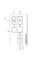
すなわち、本発明に係る標本撮像装置は、標本関連情報が記録された情報表示部を有する標本中の細胞を撮像するための第一撮像手段と、前記第一撮像手段によって撮像された細胞画像を表示するための表示手段と、前記標本関連情報を読み取るための読み取り手段と、前記情報表示部を撮像するための第二撮像手段と、前記読み取り手段によって前記標本関連情報が読み取られた場合には、その標本関連情報を前記細胞画像とともに前記表示手段に表示し、前記読み取り手段によって前記標本関連情報が読み取られなかった場合には、前記第二撮像手段で撮像した情報表示部の画像を前記細胞画像とともに前記表示手段に表示する制御手段と、を備えたものである。
In order to achieve the above object, the present invention takes the following technical means.
That is, the sample imaging device according to the present invention includes a first imaging unit for imaging a cell in a sample having an information display unit in which sample-related information is recorded, and a cell image captured by the first imaging unit. When the specimen-related information is read by the display means for displaying, the reading means for reading the specimen-related information, the second imaging means for imaging the information display unit, and the reading means When the specimen-related information is displayed on the display means together with the cell image, and the specimen-related information is not read by the reading means, an image of the information display unit imaged by the second imaging means is displayed on the cell. Control means for displaying on the display means together with the image.
上記した本発明に係る標本撮像装置によれば、読み取り手段によって標本関連情報が読み取られた場合(通常時)には、制御手段は、その標本関連情報を細胞画像とともに表示手段に表示する。他方、読み取り手段によって標本関連情報が読み取られなかった場合(異常時)には、制御手段は、第二撮像手段で撮像した情報表示部の画像を細胞画像とともに表示手段に表示する。
このため、標本関連情報の情報表示部の画像に基づいて、細胞画像が得られた標本とその提供主体(患者)とを一致させることが可能となり、これにより、検査済みの標本のデータを廃棄処分として再検査したり、標本の提供主体を取り違えたりするのを未然に防止することができる。
According to the above-described sample imaging device according to the present invention, when the sample related information is read by the reading unit (normal time), the control unit displays the sample related information together with the cell image on the display unit . On the other hand, when the specimen-related information is not read by the reading means (at the time of abnormality), the control means displays the image of the information display section imaged by the second imaging means on the display means together with the cell image.
For this reason, it is possible to match the specimen from which the cell image has been obtained with the provider (patient) based on the image of the information display section of the specimen related information, thereby discarding the data of the examined specimen. It is possible to prevent a re-inspection as a disposal or a mistake in the specimen providing entity.
本発明に係る標本撮像装置において、前記第一撮像手段で撮像された細胞画像に基づいて前記標本に含まれる細胞を分析するための分析手段を備え、
前記制御手段は、前記読み取り手段によって前記標本関連情報が読み取られた場合には、その標本関連情報を前記細胞画像および/または前記分析手段による分析結果とともに前記表示手段に表示し、前記読み取り手段によって前記標本関連情報が読み取られなかった場合には、第二撮像手段で撮像した情報表示部の画像を前記細胞画像および/または前記分析手段による分析結果とともに前記表示手段に表示することが好ましい。
In the sample imaging apparatus according to the present invention comprises analyzing means for analyzing cells contained in the specimen based on the captured cell image in the first image pickup means,
When the specimen-related information is read by the reading means , the control means displays the specimen-related information on the display means together with the cell image and / or the analysis result by the analyzing means, and the reading means When the specimen related information is not read, it is preferable to display the image of the information display unit imaged by the second imaging unit on the display unit together with the cell image and / or the analysis result by the analyzing unit .
また、本発明に係る標本撮像装置において、前記標本関連情報の情報表示部は、より具体的には、前記標本関連情報を含むバーコードが表示されたコード表示部と、同標本関連情報を含むテキスト情報が表示されたテキスト表示部とから構成することができる。
この場合、前記読み取り手段としてはバーコードリーダを採用し、前記第二撮像手段としては前記テキスト表示部を撮像可能なカメラを採用すればよい。
上記バーコードには、一次元バーコードだけでなく二次元バーコードを採用することができる。このうち、二次元バーコードとしては、従前の一次元バーコードを積み重ねたような形状のスタック型二次元コード(CODE49、CODE16K及びPDF417等)や、碁盤上に白と黒の点を並べたような形状のマトリックス型二次元コード(QRコード及びマキシコード等)を採用することができる。
特に、上記二次元バーコードの場合には、一次元バーコードと比較して数10倍〜数100倍の情報を記録することができる。
In the sample imaging device according to the present invention, more specifically, the information display unit of the sample related information includes a code display unit on which a barcode including the sample related information is displayed, and the sample related information. And a text display unit on which text information is displayed.
In this case, before the bar code reader employs as Ki読 seen up means, as the second imaging means may be employed capable of imaging cameras the text display unit.
As the barcode, not only a one-dimensional barcode but also a two-dimensional barcode can be adopted. Among them, as 2D barcodes, it seems that the stack type 2D code (CODE49, CODE16K, PDF417, etc.) shaped like a stack of previous 1D barcodes, and white and black dots arranged on the board. A matrix-type two-dimensional code (QR code, maxi code, etc.) with any shape can be adopted.
In particular, in the case of the above two-dimensional barcode, information several tens to several hundred times as much as that of a one-dimensional barcode can be recorded.
また、本発明に係る標本撮像装置において、前記読み取り手段と前記第二撮像手段とが、共通の一つの読み取り手段により構成することが好ましい。
このため、部品点数が少なくなり、コストダウン、故障の低減等が可能になる。
Further, in the sample imaging apparatus according to the present invention, and the reading means and the second imaging means is preferably constituted by one common reading means.
For this reason, the number of parts is reduced, and it is possible to reduce costs and reduce failures.
また、本発明に係る標本分析装置において、前記制御手段は、前記読み取り手段によって前記標本関連情報が読み取られなかった場合には、前記情報表示部の撮像を行うよう前記第二撮像手段を制御することが好ましい。
更に、前記標本関連情報が識別情報を含んでおれば、前記制御手段は、前記読み取り手段によって前記識別情報が読み取られなかった場合には、当該識別情報とは区別可能な仮の識別番号を前記標本に付与し、その仮の識別番号が付与された標本についてのみ前記標本関連情報の情報表示部の撮像を行うよう前記第二撮像手段を制御することが好ましい。
In the sample analyzer according to the present invention, the control unit controls the second imaging unit to perform imaging of the information display unit when the sample-related information is not read by the reading unit. It is preferable.
Further, if the specimen-related information includes identification information, the control means sets a temporary identification number that is distinguishable from the identification information when the identification information is not read by the reading means. It is preferable to control the second imaging unit so that the information display unit of the sample related information is imaged only for the sample that is given to the sample and the temporary identification number is given.
この場合、通常の識別情報とは区別可能な仮の識別番号を付与しているので、読み取り手段での読み取りの失敗を当該仮の識別番号の存在によって認識することができる。
そして、そのような仮の識別番号が付与された標本についてのみ標本関連情報の情報表示部の撮像を行うようにしたので、読み取り手段での読み取りが成功している通常の標本についてはその情報表示部の撮像が行われない。このため、標本関連情報の情報表示部の画像データを格納する記憶領域を必要最小限に止めることができる。
In this case, the normal identification information because it imparts the identification number of the distinct temporary, it is possible to recognize the failure of reading at read-section by the presence of the identification number of the temporary.
And, since as taking an information display portion of the sample-related information only for specimens such temporary identification number is assigned, for a typical specimens are read in read-means are successful the The information display unit is not imaged. For this reason, it is possible to minimize the storage area for storing the image data of the information display section of the specimen related information.
また、本発明に係る標本撮像装置は、標本関連情報が記録された情報表示部を有する標本中の細胞を撮像するための第一撮像手段と、
前記第一撮像手段によって撮像された細胞画像を表示するための表示手段と、
前記標本関連情報を読み取るための読み取り手段と、
前記情報表示部を撮像するための第二撮像手段と、
前記読み取り手段によって前記標本関連情報が読み取られた場合には、その標本関連情報を前記細胞画像および前記第二撮像手段によって撮像された情報表示部の画像とともに前記表示手段に表示し、前記読み取り手段によって前記標本関連情報が読み取られなかった場合には、前記第二撮像手段で撮像した情報表示部の画像を前記細胞画像とともに前記表示手段に表示する制御手段と、を備えたものである。
Further, the specimen imaging device according to the present invention includes a first imaging means for imaging cells in a specimen having an information display unit in which specimen related information is recorded,
Display means for displaying the cell image captured by the first imaging means,
Reading means for reading the specimen-related information;
Second imaging means for imaging the information display unit;
When the specimen-related information is read by the reading means, the specimen-related information is displayed on the display means together with the cell image and an image of the information display section imaged by the second imaging means, and the reading means When the specimen-related information is not read, control means for displaying an image of the information display section imaged by the second imaging means on the display means together with the cell image is provided.
上記した本発明に係る標本撮像装置によれば、読み取り手段によって標本関連情報が読み取られた場合(通常時)には、制御手段は、その標本関連情報を細胞画像および第二撮像手段によって撮像された情報表示部の画像とともに表示手段に表示する。他方、読み取り手段によって標本関連情報が読み取られなかった場合(異常時)には、制御手段は、第二撮像手段で撮像した情報表示部の画像を細胞画像とともに表示手段に表示する。
このため、標本関連情報の読み取り可否にかかわらず、第二撮像手段によって撮像された情報表示部の画像を表示するので、読み取り手段を制御する必要がなくなり、制御プログラムが簡潔になる。
また、標本関連情報の情報表示部の画像に基づいて、細胞画像が得られた標本とその提供主体(患者)とを一致させることが可能となり、これにより、検査済みの標本のデータを廃棄処分として再検査したり、標本の提供主体を取り違えたりするのを未然に防止することができる。
According to the above-described sample imaging device according to the present invention, when the sample related information is read by the reading unit (normal time), the control unit captures the sample related information by the cell image and the second imaging unit. Displayed on the display means together with the image of the information display section. On the other hand, when the specimen-related information is not read by the reading means (at the time of abnormality), the control means displays the image of the information display section imaged by the second imaging means on the display means together with the cell image.
Therefore, regardless of the reading whether the sample-related information, since the display image of the information display unit captured by the second imaging means, gets rid necessary to control the reading means, the control program becomes concise.
In addition, it is possible to match the specimen from which the cell image was obtained with the provider (patient) based on the image of the information display section of the specimen related information, thereby disposing of the data of the examined specimen. As a result, it is possible to prevent re-examination and misunderstanding of the specimen providing entity.
また、本発明は、前記撮像手段を備えていない標本分析装置として構成することもでき、この場合には、標本関連情報が記録された情報表示部を有する標本に含まれる成分を分析するための分析手段と、前記標本関連情報を読み取るための読み取り手段と、を備えている標本分析装置において、
前記分析手段によって分析された分析結果を表示するための表示手段と、
前記情報表示部を撮像するための撮像手段と、
前記読み取り手段によって前記標本関連情報が読み取られた場合には、その標本関連情報を前記分析結果とともに前記表示手段に表示し、前記読み取り手段によって前記標本関連情報が読み取られなかった場合には、前記撮像手段で撮像した情報表示部の画像を前記分析結果とともに前記表示手段に表示する制御手段と、を備えていることを特徴とする。
The present invention can also be configured as a sample analyzer that does not include the imaging means, and in this case, for analyzing a component contained in a sample having an information display unit in which sample-related information is recorded. In a sample analyzer comprising: an analyzing unit; and a reading unit for reading the sample related information;
Display means for displaying the analysis results analyzed by said analyzing means,
Imaging means for imaging the information display unit;
When the sample related information is read by the reading means, the sample related information is displayed on the display means together with the analysis result, and when the sample related information is not read by the reading means, And a control means for displaying an image of the information display section imaged by the imaging means on the display means together with the analysis result.
以上の通り、本発明によれば、予め標本に付された識別情報の読み取りに失敗してもその標本を確実に識別できるので、標本の取り違えや再検査を防止することができる。 As described above, according to the present invention, even if the reading of the identification information previously attached to the specimen fails, the specimen can be reliably identified, so that it is possible to prevent the specimen from being mixed up and reexamined.
以下、図面を参照しつつ、本発明の実施形態を説明する。
〔システム全体構成〕
図1は本発明を実施するための一例である血液像分析システム1の外観構成を示し、図2はそのシステム構成を示している。
本実施形態の血液像分析システム1は、病院等の血液検査を行う施設に設置されるものであり、試験管Pを搬送する搬送装置2と、血液標本を自動的に作成する標本作製装置3と、カセット供給ユニット4(図2参照)と、血液標本の成分を撮像して血球の分類等を行う自動分析装置5とから構成されている。これらの各装置2〜5はネットワーク(LAN)6を介してホストコンピュータ7(図2参照)に接続されている。
Hereinafter, embodiments of the present invention will be described with reference to the drawings.
[Entire system configuration]
FIG. 1 shows an external configuration of a blood image analysis system 1 which is an example for carrying out the present invention, and FIG. 2 shows the system configuration.
The blood image analysis system 1 of the present embodiment is installed in a facility that performs blood tests such as a hospital, and includes a
〔各装置の外観構造〕
上記各装置2〜5のうち、自動分析装置5は、標本作製装置3で作成された血液標本をデジタル画像処理して自動的に血球の分類を行う装置である。標本作製装置3は、自動分析装置5で分析可能な自動分析用の標本と、人間の目視で分析可能な目視用の標本の二種類の標本を作製する装置である。
図1に示すように、標本作製装置3は、前面右端部に操作部としてのタッチパネル8を有する箱体を備え、この箱体の前面側に前記搬送装置2が配置されている。
標本作成装置3の左側には自動分析装置5が配置されている。この自動分析装置5は、後述する自動撮像装置10とパーソナルコンピュータよりなる血液像分析装置11とから構成されている。図2に示すように、これら標本作成装置3及び血液像分析装置11の各制御部は前記ネットワーク6を介してホストコンピュータ7に接続されている。
[Appearance structure of each device]
Of the
As shown in FIG. 1, the
An
図1に示すように、搬送装置2は、左右方向に長い搬送溝12が上面に形成された横長の扁平な箱体で構成され、その搬送溝12には、血液が充填された試験管Pを収納する検体ラック13が収納されている。この検体ラック13は搬送溝12に沿って自動的に搬送される。標本作成装置3の前面左側部に設けた取り入れ口14には、上記試験管Pを搬送装置2から受け取るためのハンド部材15が出退自在に設けられている。
このため、搬送装置2の搬送溝12の右端部分に試験管P入りの検体ラック13を載置すると、その検体ラック13が自動的に左側に搬送されて取り入れ口14に至り、上記ハンド部材15によって一つの試験管Pが抽出されて標本作成装置3の内部に取り入れられるようになっている。
As shown in FIG. 1, the
For this reason, when the
〔標本作製装置〕
図1及び図2に示すように、標本作成装置3は、標本カセット32(図5参照)を収容するカセット収容部17と、この収容部17内のカセット32を装置内に搬送する第一カセット搬送部18と、標本プレート25(図4及び図5参照)に対して標本作製処理を行って上記搬送部18を通過するカセット32にそのプレート25を挿入する標本作製部19とを備えている。
更に、この標本作製装置3は、標本カセット32に収容された標本プレート25に染色処理を行う染色部20と、染色処理済みの標本カセット32を装置外に搬送する第二カセット搬送部21と、人間の目視で分析可能な目視用の標本が収容されたカセット32をいったん保管しておくための保管部22と、これらの各部の動作を制御する制御部23とを備えている。
自動分析装置5で分析可能な自動分析用の標本が収容されたカセット32は、第二カセット搬送部21によってカセット供給ユニット4のカセット収容部35に搬送される。
[Sample preparation equipment]
As shown in FIGS. 1 and 2, the
Further, the
The
図4及び図5に示すように、上記標本プレート25は、ほぼ長方形枠状に形成されたプレート本体26と、このプレート本体26の枠内に嵌め込まれた標本担持体としての標本形成部27とを備えている。プレート本体26の上端部には、日付、検体提供者及びID番号よりなる識別情報や検体に関するその他の諸情報(標本関連情報)を記録するための情報表示部28が設けられている。なお、標本形成部27には検体の血液標本Sが塗抹されている。
この情報表示部28は、プレート本体26の上端部に左右に並んで表示された二種類の表示部29,30よりなる。このうちの一方(図4の左側)は、識別情報を含む二次元バーコードが表示されたコード表示部29であり、他方(図4の右側)は、識別情報を含むテキスト情報が表示されたテキスト表示部30である。
As shown in FIGS. 4 and 5, the
The
図例では、上記テキスト表示部30には、上から順に、日付、検体提供者の氏名(○○ ○○)及びID番号が記載されている。また、コード表示部29には一次元バーコードを採用することもできる。
図5に示すように、標本カセット32は、ほぼ逆T字状に形成された扁平なケース本体33よりなる。このケース本体34の上端部中央部には標本プレート25の挿通口34が形成されていて、この挿通口34は正面視で下方に切り欠き形成されている。従って、当該挿通口34に向かって標本プレート25を差し込むことにより、情報表示部28だけが外部に露出した状態で当該標本プレート25を標本カセット32に収納させることができる。なお、図示していないが、前記試験管Pにも、標本プレート25と対応する識別情報を含む情報表示部が設けられている。
In the illustrated example, the text, the name of the sample provider (XXXXX), and the ID number are described in the
As shown in FIG. 5, the
図2に戻り、前記標本作製部19は、血液の吸引分注機能、血液の塗抹機能及び標本プレート25の挿入機能を有する。
すなわち、この標本作製部19は、前記ハンド部材15で取り入れられた試験管Pから血液を吸引し、標本プレート25の標本形成部27にその血液を滴下して塗抹する機能を有する。その後、塗抹後の標本プレート25は、第一カセット搬送部18を通過する標本カセット32に挿入され、当該カセット32と一体化される。
なお、図示していないが、標本作製部19は、試験管P及び標本プレート25の各識別情報の少なくともID番号を読み取る機能も備えており、標本作製装置3の制御部23は、その試験管Pと同じID番号を有する標本プレート25に対して上記の標本作製作業を標本作製部19に行わせる。
Returning to FIG. 2, the
That is, the
Although not shown, the
〔カセット供給ユニット〕
図2に示すように、カセット供給ユニット4は、標本作製装置3と自動撮像装置10の間に介在されており、標本作成装置3から搬送された染色済みの標本プレート25を有する標本カセット32を収容するカセット収容部35と、この収容部35の下流側に配置されたカセット保管部36と、カセット供給部37とを備えている。
標本カセット収容部に収容された標本プレート25入りの標本カセット32は、カセット供給部37から自動撮像装置10の標本プレート取出部40に送られるようになっている。また、標本プレート取出部40において標本プレート25が取り出された標本カセット32は、カセット供給部37によってカセット保管部36に保管される。
[Cassette supply unit]
As shown in FIG. 2, the
The
〔自動撮像装置〕
図2に示すように、本実施形態の自動分析装置5は、検体の血液標本Sを拡大して撮像する機能を有する前記自動撮像装置10と、細胞の識別分類集計やそれに必要な画像処理等を行う前記血液像分析装置11とを備えており、これらの両装置10,11は互いに通信可能に接続されている。
[Automatic imaging device]
As shown in FIG. 2, the
このうち、自動撮像装置10は、カセット供給ユニット4から供給された標本カセット32から標本プレート25を取り出す標本プレート取出部40と、標本プレート取出部40によって取り出された標本プレート25を装置内部で搬送する標本プレート搬送部39と、標本プレート搬送部39によって搬送された標本プレート25の標本形成部27に塗抹されている血液像を拡大して撮像する第一撮像手段である撮像部41と、撮像された標本プレート25を収納する標本プレート収納部45とを備えている。標本プレート収納部45には、標本プレート25を収納する収納カセットが収納されている。
また、この自動撮像装置10は、標本プレート搬送部39を通過する標本プレート25のコード表示部29に記録されている二次元バーコードを読み取って、検体のID番号等の識別情報を獲得するためのバーコードリーダよりなる読み取り手段42と、同搬送部39を通過する標本プレート25のテキスト表示部30をそのまま撮像するCCDカメラ等よりなる第二撮像手段43とを備えている。
Among these, the
Further, the
撮像部41には、標本形成部27に塗抹された血液標本Sを拡大して観察できる顕微鏡と、その標本に含まれている白血球やその他の血球の画像(血液の成分画像ないし細胞画像)を撮像するCCDカメラと、このカメラから出力されたRGBカラー画像をA/D変換して記憶する画像メモリが内蔵されている。
この自動撮像装置10における撮像部41の制御その他の各種制御や、ネットワークボードを介したネットワーク側とのデータ伝送その他の通信制御は、当該自動撮像装置5の内部に設けられた制御部44によって行われる。
The
Control of the
この自動撮像装置10の制御部44は、図3に示すように、CPU46と、ROM47と、RAM48と、入出力インターフェース49とを備えている。ROM47には、オペレーティングシステムと撮像部41の動作を制御するための制御プログラム、及び、その制御プログラムの実行に必要なデータが格納されている。
CPU46は、上記制御プログラムをRAM48にロードして、或いは、ROM47から直接実行する。このようにしてCPU46が処理した結果のデータは、入出力インターフェース49を介して、自動撮像装置10の各部又は当該装置10の外部(血液像分析装置11等)へ送信され、また、CPU46の処理に必要なデータは、自動撮像装置10の各部又は当該装置10の外部から入出力インターフェース49を通じて受信される。CPU46は、上記制御プログラムを実行することで後述する図6のフローチャートで示す制御動作を行うことが可能である。
As shown in FIG. 3, the
The
〔血液像分析装置〕
図2に示すように、血液像分析装置11は、CPU51と、ROM52と、RAM53と、CRTや液晶ディスプレイ等よりなる表示装置54と、キーボード(専用のものを含む。)55やマウス56等よりなる入力装置と、大容量記憶装置としてのハードディスク57とを備えている。なお、図1には示されていないが、この血液像分析装置11にはプリンタ58が接続されている。
[Blood image analyzer]
As shown in FIG. 2, the
ROM52には、オペレーティングシステムや当該分析装置11での画像処理や細胞の識別分類集計等を実行するための制御プログラム、及び当該プログラムの実行に必要なデータが格納されている。
CPU51は、上記制御プログラムをRAM53にロードして、或いは、ROM52から直接実行する。このようにしてCPU51が処理した結果のデータは、図外のネットワークボードを介して、血液像分析装置11の外部(自動撮像装置10等)へ送信され、また、CPU51の処理に必要なデータは、血液像分析装置11の外部から図外のネットワークボードを通じて受信される。
The
The
血液像分析装置11のCPU51は、上記制御プログラムを実行することにより、血液の細胞画像をデータ処理し、血液細胞の認識分類に必要な特徴量の演算を行い、その特徴量をもとに細胞の識別分類集計を行う。
特徴抽出処理は、白血球の標本画像の核画素を核に相当する画素、細胞質に関する画素、それ以外の画素にわけることによって行われる。分類処理は、核に関する特徴パラメータ、細胞質に関する特徴パラメータを用いて、対象血球の種類を識別し、血球カウント数分の血球の分類を行う。例えば、白血球(有核血球)の分類処理は、対象血球を成熟白血球6種(桿状核好中球、分葉核好中球、好酸球、好塩基球、リンパ球、単球)、未熟白血球3種(芽球、幼若顆粒球、異型リンパ球)、赤芽球に分類することで行われる。なお、6種の成熟白血球が正常な有核血球であり、3種の未熟白血球3種及び赤芽球が異常有核血球である。
The
The feature extraction processing is performed by dividing the nucleus pixel of the white blood cell specimen image into a pixel corresponding to the nucleus, a pixel related to the cytoplasm, and other pixels. In the classification process, the type of the target blood cell is identified using the feature parameter related to the nucleus and the feature parameter related to the cytoplasm, and the blood cells are classified according to the number of blood cells counted. For example, white blood cells (nucleated blood cells) are classified into six types of mature white blood cells (spotted nucleus neutrophils, segmented nucleus neutrophils, eosinophils, basophils, lymphocytes, monocytes), immature cells. It is performed by classifying into three types of leukocytes (blast, immature granulocyte, atypical lymphocyte) and erythroblast. In addition, six types of mature leukocytes are normal nucleated blood cells, three types of three immature leukocytes and erythroblasts are abnormal nucleated blood cells.
また、血液像分析装置11のCPU51は、血液像(血液の細胞画像)、上記細胞の識別分類結果(分析結果)及び前記第二撮像手段43で撮像されたテキスト表示部30の画像データを各種の方式で出力することができる。
これらのデータは、例えば図8に例示される表示画面でディスプレイ54に表示され、また、レビューのためにそれらのデータがハードディスク57に保存され、更にネットワーク6を介してホストコンピュータ7に送信される。
In addition, the
These data are displayed on the
図8は、血球の画像データ、血液の識別番号及び血液の分類結果の表示画面の一例である。
この表示画面では、血球の画像を示す表示ウィンドウ59が5つ設けられている。また、この表示画面の左上にはカセット番号とスライド(標本)番号の表示ボックス60が配置され、その右隣にはID番号用の表示ボックス61が配置されている。また、このID番号用の表示ボックス61の右隣に、テキスト表示部30の画像データを表示するための表示ボックス62が配置されている。
また、表示画面の右側にWBC(白血球)の分類結果用の表示ボックス63が配置されている。表示ウィンドウ59には、自動撮像装置10で撮像された標本プレート25の標本形成部27に塗抹されている血液像が表示される。表示ボックス60には、標本プレート25を収納するための収納カセット番号、スライド(標本)番号が表示される。
また、表示ボックス61には、標本プレート25のID番号または後述する仮のID番号が表示される。また、表示ボックス62には、第二撮像手段43によって撮像された標本プレート25のテキスト表示部30が表示される。また、表示ボックス63には、血液像分析装置11で分類されたWBC(白血球)の分類結果が表示される。
FIG. 8 is an example of a display screen of blood cell image data, blood identification number, and blood classification result.
In this display screen, five
A
The
〔自動撮像装置の処理フロー〕
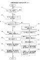
次に、自動撮像装置10での処理フローについて、図6を参照しつつ説明する。
図6に示すように、自動撮像装置10の標本プレート取出部40に設けた検知センサ(図示せず)で標本カセット32が検知されると(ステップS1)、そのカセット32から標本プレート25が取り出される(ステップS2)。
その後、バーコードリーダよりなる読み取り手段42により、標本プレート25のコード表示部29に付されているバーコードの読み取りが行われるが、かかる読み取りが適切に行われたかどうかが判定される(ステップS3)。
[Processing flow of automatic imaging equipment]
Next, a processing flow in the
As shown in FIG. 6, when the
Thereafter, the read-
このバーコードの読み取りが正常に行われた場合には、標本プレート25が撮像部41に搬送されたあと(ステップS4)、その撮像部41において標本形成部27に塗抹された血液標本Sの撮像が行われる(ステップS5)。
その後、読み取り手段42で取得したID番号を含む識別情報と、撮像部41で得られた標本画像である血液の画像データがメモリに記憶され(ステップS6)、それらの各データが血液像分析装置11に送信される(ステップS7)。
When the barcode is read normally, the
Then, reading the identification information including the acquired ID number up means 42 seen, the image data of the blood or the specimen image obtained by the
他方、印字が不明瞭である等の何らかの原因でバーコードの読み取りができなかった場合には、その標本プレート25に対して仮のID番号(例えば、エラーを意味するERRと12桁の番号)が付与される(ステップS8)。
その後、CCDカメラ等よりなる第二撮像手段43でその標本プレート25のテキスト表示部30が撮像されたあと(ステップS9)、標本プレート搬送部39によって標本プレート25が撮像部41に搬送され(ステップS10)、撮像部41において血液標本Sの撮像が行われる(ステップS11)。
続いて、上記した仮のID番号と、テキスト表示部30の画像データと、撮像部41で得られた標本画像である血液の画像データがメモリに記憶され(ステップS12)、それらの各データが血液像分析装置11に送信される(ステップS13)。
On the other hand, if the barcode cannot be read for some reason such as unclear printing, a temporary ID number for the sample plate 25 (for example, ERR and 12-digit number indicating an error) Is given (step S8).
Thereafter, after the
Subsequently, the provisional ID number, the image data of the
〔血液像分析装置の処理フロー〕
次に、血液像分析装置11での処理フローについて、図7を参照しつつ説明する。
図7に示すように、血液像分析装置11側においては、まず、本来の識別情報又は仮のID番号を自動撮像装置10から受信すると(ステップS21)、その受信した情報がメモリに記憶されるとともに(ステップS22)、その受信した情報中のID番号が読み取り手段42で読み取られた正常なID番号であるか、或いは、読み取り手段42での読み取りが失敗した場合に付与される前記仮のID番号(ERR○○)であるかを判定する(ステップS23)。
[Processing flow of blood image analyzer]
Next, a processing flow in the
As shown in FIG. 7, on the
正常なID番号が検出された場合には、血液標本Sの画像データを受信してメモリに保存するとともに(ステップS24)、その血液標本Sの画像データに基づいて血球の分類が行われ(ステップS25)、その分類結果がメモリに記憶される(ステップS26)。その後、血液標本Sの画像データと分類結果が図8に示す表示画面でディスプレイ54に表示され(ステップS27)、それらのデータがホストコンピュータ7に送信される(ステップS32)。
この場合、図8に示す表示画面において、ID番号用の表示ボックス61には正常なID番号が表示され、テキスト表示部30用の表示ボックス62には何も表示されない。
When a normal ID number is detected, image data of the blood sample S is received and stored in the memory (step S24), and blood cells are classified based on the image data of the blood sample S (step S24). S25), the classification result is stored in the memory (step S26). Thereafter, the image data and classification result of the blood sample S are displayed on the
In this case, on the display screen shown in FIG. 8, the normal ID number is displayed in the ID
他方、仮のID番号(ERR○○)が検出された場合には、血液標本Sの画像データとテキスト表示部30の画像データを受信してメモリに保存するとともに(ステップS28)、その血液標本Sの画像データに基づいて血球の分類が行われ(ステップS29)、その分類結果がメモリに記憶される(ステップS30)。その後、血液標本Sの画像データ、テキスト表示部30の画像データ及び分類結果が図8の表示画面でディスプレイ54に表示され(ステップS31)、それらのデータがホストコンピュータ7に送信される(ステップS32)。
この場合、図8に示す表示画面において、ID番号用の表示ボックス61には仮のID番号(ERR○○)が表示され、テキスト表示部30用の表示ボックス62に当該表示部30の画像データが表示される。
On the other hand, when the temporary ID number (ERROO) is detected, the image data of the blood sample S and the image data of the
In this case, on the display screen shown in FIG. 8, a temporary ID number (ERROO) is displayed in the ID
このように、本実施形態の自動分析装置5によれば、読み取り手段42がバーコードを読み取らなかった場合(異常時)でも、第二撮像手段43で撮像したテキスト表示部30の画像データが血液標本Sの画像データや血球の分類結果とともに表示装置54やホストコンピュータ7に出力されるので、そのテキスト表示部30の画像データに基づいて、血液標本Sの画像データや血球の分類結果を有する検査済みの標本プレート25とその提供主体(患者)とを一致させることが可能となる。
このため、検査済みの標本プレート25のデータを廃棄処分として再検査する必要がなくなるとともに、標本プレート25の提供主体を取り違えるのを未然に防止することができる。
Thus, according to the
For this reason, it is not necessary to re-inspect the data of the inspected
また、本実施形態の自動分析装置5では、通常のID情報とは区別可能な仮のID番号(ERR○○)を付与しているので、読み取り手段42での読み取りの失敗を当該仮のID番号の存在によって察知することができる。
そして、そのような仮のID番号が付与された標本プレート25についてのみテキスト表示部30の撮像を行い、読み取り手段42での読み取りが成功している通常の標本プレート25についてはテキスト表示部30の撮像を行わないので、テキスト表示部30の画像データを格納する記憶領域を必要最小限に止めることができる。
Further, in the
Then, captures an image of the
本発明は、上記実施形態に限定されるものではない。
例えば、撮像されたテキスト表示部30をそのまま画像データと出力するだけではなく、テキスト表示部30に手書き文字や印字された文字を撮像し、撮像した画像に基づいて、前もって記憶されたパターンとの照合により文字を特定し、文字データとして出力することができるOCRを採用することもできる。この場合には、テキスト表示部30を画像データではなく文字情報として出力することができる。
The present invention is not limited to the above embodiment.
For example, not only the captured
また、読み取り手段42と第二撮像手段43を一台のカメラで兼用することもできる。この場合の兼用カメラは、通常時はコード表示部29の二次元バーコードを読み取り、その読み取りができない場合に撮像範囲を移動させてテキスト表示部30を撮像するように構成すればよい。
更に、上記実施形態では、血液標本の画像と分析結果の双方を出力できる自動分析装置5に本発明を適用した場合を例示したが、それらのうちの一方のデータだけを出力する装置にも本発明を適用することができる。また、本発明は、骨髄液や尿等の血液以外の生体液を分析対象ないし撮像対象とする装置にも適用することができる。
Further, a read-
Furthermore, in the above-described embodiment, the case where the present invention is applied to the
また、上記実施形態の自動分析装置5では、通常のID情報とは区別可能な仮のID番号(ERR○○)を付与し、仮のID番号が付与された標本プレート25についてのみテキスト表示部30の撮像を行い、読み取り手段42での読み取りが成功している通常の標本プレート25についてはテキスト表示部30の撮像を行わないようにしたが、通常のID情報あるなしにかかわらず、標本プレート25の表示部30を撮像するようにしても良い。
Further, in the
また、上記実施形態の自動分析装置5では、血球の画像データ、血液の識別番号及び血液の分類結果の表示画面において、自動撮像装置10で撮像された血液像と、標本プレート25のID番号または仮の番号、第二撮像手段43によって撮像された標本プレート25のテキスト表示部30、血液像分析装置11で分類されたWBC(白血球)の分類結果を表示するようにしたが、ID番号または仮のID番号、テキスト表示部30(ID番号が読み取れなかった場合に表示される)並びに血液像および分類結果のいずれか一方を表示するようにしても良い。
In the
更に、上記実施形態の自動分析装置5では、血液像分析装置11に設けられた表示装置(表示手段)54に血液像や分析結果とともに識別情報を表示するようにしたが、ホストコンピュータ7やその他のクライアントPCに付属している表示装置(表示手段)に対してそれらの画像データや分析結果等を表示させるようにしても良い。
Further, in the
1 血液像分析システム
2 搬送装置
3 標本作製装置
4 カセット供給ユニット
5 自動分析装置(標本撮像装置、標本分析装置)
10 自動撮像装置
11 血液像分析装置
25 標本プレート(標本)
28 情報表示部
29 コード表示部
30 テキスト表示部
41 撮像部(第一撮像手段)
42 読み取り手段
43 第二撮像手段
44 自動撮像装置の制御部(制御手段)
51 血液像分析装置のCPU(分析手段、制御手段)
54 表示装置(表示手段)
P 試験管
S 血液標本
DESCRIPTION OF SYMBOLS 1 Blood
10
28
42 control unit of the read-
51 CPU of blood image analyzer (analysis means, control means)
54 Display device ( display means)
P Test tube S Blood specimen
Claims (11)
前記第一撮像手段によって撮像された細胞画像を表示するための表示手段と、
前記標本関連情報を読み取るための読み取り手段と、
前記情報表示部を撮像するための第二撮像手段と、
前記読み取り手段によって前記標本関連情報が読み取られた場合には、その標本関連情報を前記細胞画像とともに前記表示手段に表示し、前記読み取り手段によって前記標本関連情報が読み取られなかった場合には、前記第二撮像手段で撮像した情報表示部の画像を前記細胞画像とともに前記表示手段に表示する制御手段と、
を備えている標本撮像装置。 A first imaging means for imaging cells in a specimen having an information display section in which specimen-related information is recorded;
Display means for displaying the cell image captured by the first imaging means,
Reading means for reading the specimen-related information;
Second imaging means for imaging the information display unit;
When the specimen related information is read by the reading means, the specimen related information is displayed on the display means together with the cell image, and when the specimen related information is not read by the reading means, Control means for displaying an image of the information display section imaged by the second imaging means on the display means together with the cell image;
A specimen imaging device comprising:
前記制御手段は、前記読み取り手段によって前記標本関連情報が読み取られた場合には、その標本関連情報を前記細胞画像および/または前記分析手段による分析結果とともに前記表示手段に表示し、前記読み取り手段によって前記標本関連情報が読み取られなかった場合には、第二撮像手段で撮像した情報表示部の画像を前記細胞画像および/または前記分析手段による分析結果とともに前記表示手段に表示する請求項1に記載の標本撮像装置。 Comprising analysis means for analyzing cells contained in the specimen based on the cell image imaged by the first imaging means;
When the specimen-related information is read by the reading means, the control means displays the specimen-related information on the display means together with the cell image and / or the analysis result by the analyzing means, and the reading means 2. The display unit according to claim 1, wherein when the sample-related information is not read, an image of the information display unit captured by the second imaging unit is displayed on the display unit together with the cell image and / or the analysis result by the analysis unit. Specimen imaging device.
前記制御手段は、前記読み取り手段によって前記識別情報が読み取られなかった場合には、当該識別情報とは区別可能な仮の識別番号を前記標本に付与し、その仮の識別番号が付与された標本についてのみ前記標本関連情報の情報表示部の撮像を行うよう前記第二撮像手段を制御する請求項6に記載の標本撮像装置。 The specimen related information includes identification information;
The control means, when the identification information is not read by the reading means, gives a temporary identification number that is distinguishable from the identification information to the specimen, and the specimen to which the temporary identification number is given The sample imaging apparatus according to claim 6, wherein the second imaging unit is controlled so as to perform imaging of the information display unit of the sample related information only for the.
前記読み取りステップにより前記標本関連情報が読み取られなかった場合には、前記情報表示部を撮像するステップと、
前記標本の細胞を撮像するステップと、
前記読み取りステップにより前記標本関連情報が読み取られた場合には、その標本関連情報を撮像された細胞画像とともに表示し、前記読み取りステップにより前記標本関連情報が読み取られなかった場合には、撮像された情報表示部の画像を撮像された細胞画像とともに表示するステップと、
を含む標本撮像方法。 Reading the sample related information of the sample having an information display unit in which the sample related information is recorded;
When the sample-related information is not read by the reading step, imaging the information display unit;
Imaging cells of the specimen;
When the sample related information is read by the reading step, the sample related information is displayed together with the captured cell image, and when the sample related information is not read by the reading step, the sample related information is displayed. Displaying an image of the information display unit together with the captured cell image;
A specimen imaging method including:
前記第一撮像手段によって撮像された細胞画像を表示するための表示手段と、
前記標本関連情報を読み取るための読み取り手段と、
前記標本関連情報の情報表示部を撮像するための第二撮像手段と、
を備えている標本撮像装置を制御するコンピュータのプログラムであって、
前記読み取り手段によって前記標本関連情報が読み取られた場合には、その標本関連情報を前記細胞画像とともに前記表示手段に表示し、前記標本関連情報が読み取られなかった場合には、前記第二撮像手段で撮像した情報表示部の画像を前記細胞画像とともに前記表示手段に表示するステップを、前記コンピュータに実行させるためのプログラム。 A first imaging means for imaging cells in a specimen having an information display section in which specimen-related information is recorded;
Display means for displaying the cell image captured by the first imaging means,
Reading means for reading the specimen-related information;
Second imaging means for imaging the information display section of the specimen related information;
A computer program for controlling a specimen imaging apparatus comprising:
When the specimen-related information is read by the reading means, the specimen-related information is displayed on the display means together with the cell image, and when the specimen-related information is not read, the second imaging means The program for making the said computer perform the step which displays the image of the information display part imaged by 1 with the said cell image on the said display means.
前記第一撮像手段によって撮像された細胞画像を表示するための表示手段と、
前記標本関連情報を読み取るための読み取り手段と、
前記情報表示部を撮像するための第二撮像手段と、
前記読み取り手段によって前記標本関連情報が読み取られた場合には、その標本関連情報を前記細胞画像および前記第二撮像手段によって撮像された情報表示部の画像とともに前記表示手段に表示し、前記読み取り手段によって前記標本関連情報が読み取られなかった場合には、前記第二撮像手段で撮像した情報表示部の画像を前記細胞画像とともに前記表示手段に表示する制御手段と、
を備えている標本撮像装置。 A first imaging means for imaging cells in a specimen having an information display section in which specimen-related information is recorded;
Display means for displaying the cell image captured by the first imaging means,
Reading means for reading the specimen-related information;
Second imaging means for imaging the information display unit;
When the specimen-related information is read by the reading means, the specimen-related information is displayed on the display means together with the cell image and an image of the information display section imaged by the second imaging means, and the reading means If the sample related information is not read by the control means for displaying the image of the information display unit imaged by the second imaging means on the display means together with the cell image,
A specimen imaging device comprising:
前記標本関連情報を読み取るための読み取り手段と、
前記分析手段によって分析された分析結果を表示するための表示手段と、
前記情報表示部を撮像するための撮像手段と、
前記読み取り手段によって前記標本関連情報が読み取られた場合には、その標本関連情報を前記分析結果とともに前記表示手段に表示し、前記読み取り手段によって前記標本関連情報が読み取られなかった場合には、前記撮像手段で撮像した情報表示部の画像を前記分析結果とともに前記表示手段に表示する制御手段と、を備えていることを特徴とする標本分析装置。 An analysis means for analyzing a component contained in a sample having an information display unit in which sample-related information is recorded;
Reading means for reading the specimen-related information;
Display means for displaying the analysis results analyzed by said analyzing means,
Imaging means for imaging the information display unit;
When the sample related information is read by the reading means, the sample related information is displayed on the display means together with the analysis result, and when the sample related information is not read by the reading means, And a control means for displaying an image of the information display section imaged by the imaging means on the display means together with the analysis result.
Priority Applications (2)
| Application Number | Priority Date | Filing Date | Title |
|---|---|---|---|
| JP2005287463A JP5132050B2 (en) | 2005-09-30 | 2005-09-30 | Specimen imaging apparatus, specimen imaging method, program for controlling the apparatus, and specimen analyzer |
| US11/540,156 US7936912B2 (en) | 2005-09-30 | 2006-09-29 | Sample imaging apparatus, sample analyzing apparatus, and sample imaging method |
Applications Claiming Priority (1)
| Application Number | Priority Date | Filing Date | Title |
|---|---|---|---|
| JP2005287463A JP5132050B2 (en) | 2005-09-30 | 2005-09-30 | Specimen imaging apparatus, specimen imaging method, program for controlling the apparatus, and specimen analyzer |
Publications (3)
| Publication Number | Publication Date |
|---|---|
| JP2007101199A JP2007101199A (en) | 2007-04-19 |
| JP2007101199A5 JP2007101199A5 (en) | 2008-11-06 |
| JP5132050B2 true JP5132050B2 (en) | 2013-01-30 |
Family
ID=37902320
Family Applications (1)
| Application Number | Title | Priority Date | Filing Date |
|---|---|---|---|
| JP2005287463A Active JP5132050B2 (en) | 2005-09-30 | 2005-09-30 | Specimen imaging apparatus, specimen imaging method, program for controlling the apparatus, and specimen analyzer |
Country Status (2)
| Country | Link |
|---|---|
| US (1) | US7936912B2 (en) |
| JP (1) | JP5132050B2 (en) |
Families Citing this family (19)
| Publication number | Priority date | Publication date | Assignee | Title |
|---|---|---|---|---|
| JP5466825B2 (en) * | 2008-01-23 | 2014-04-09 | シスメックス株式会社 | Cell image processing system, cell image display system, and cell image display method |
| JP5301232B2 (en) | 2008-09-30 | 2013-09-25 | シスメックス株式会社 | Blood cell image display device, sample analysis system, blood cell image display method, and computer program |
| JP5557994B2 (en) * | 2008-10-28 | 2014-07-23 | シスメックス株式会社 | Sample processing system and blood cell image classification apparatus |
| JP5438962B2 (en) * | 2008-12-25 | 2014-03-12 | シスメックス株式会社 | Cell image display device |
| JPWO2011004568A1 (en) * | 2009-07-08 | 2012-12-20 | 株式会社ニコン | Fertilized egg observation image processing method, image processing program, image processing apparatus, and fertilized egg manufacturing method |
| WO2014045759A1 (en) * | 2012-09-24 | 2014-03-27 | ソニー株式会社 | Image display device, method, program, and microscope system |
| JP6016560B2 (en) | 2012-09-28 | 2016-10-26 | シスメックス株式会社 | Specimen conveying apparatus and specimen imaging system |
| JP5963631B2 (en) | 2012-09-28 | 2016-08-03 | シスメックス株式会社 | Specimen storage device, specimen storage method, and storage tool |
| JP6009890B2 (en) | 2012-09-28 | 2016-10-19 | シスメックス株式会社 | Specimen transport device and specimen inspection system |
| JP5995631B2 (en) | 2012-09-28 | 2016-09-21 | シスメックス株式会社 | Specimen conveying apparatus, specimen inspection system, and specimen conveying method |
| JP6581965B2 (en) | 2013-03-13 | 2019-09-25 | タホ インスティチュート フォー ルーラル ヘルス リサーチ, エルエルシー | Portable blood counting monitor |
| EP3276328B1 (en) * | 2016-07-29 | 2020-12-02 | Sysmex Corporation | Smear transporting apparatus, smear image capture system, and smear analysis system |
| JP6732331B2 (en) * | 2016-10-03 | 2020-07-29 | 溝口 さとし | System for preventing sample mix-up in pathological diagnosis |
| EP3625538A4 (en) | 2017-11-27 | 2021-02-17 | Leica Biosystems Imaging, Inc. | Slide rack determination system |
| EP3773237A4 (en) * | 2018-04-05 | 2022-01-19 | Instapath, Inc. | Disposable biopsy staining kit and related methods and systems |
| US20190331560A1 (en) * | 2018-04-05 | 2019-10-31 | Instapath, Inc. | Disposable Biopsy Staining Kit and Related Methods and Systems |
| JP2022540190A (en) * | 2019-07-09 | 2022-09-14 | ザ リージェンツ オブ ザ ユニバーシティ オブ カリフォルニア | Automatic rapid cytodiagnosis device and staining agent |
| US11183294B2 (en) * | 2019-08-30 | 2021-11-23 | International Business Machines Corporation | Automatic detection and replacement of identifying information in images using machine learning |
| WO2022056054A1 (en) * | 2020-09-10 | 2022-03-17 | Instapath, Inc. | Systems for delivery of a liquid to and removal of a liquid from a sample |
Family Cites Families (8)
| Publication number | Priority date | Publication date | Assignee | Title |
|---|---|---|---|---|
| JPS60162955A (en) * | 1984-02-03 | 1985-08-24 | Hitachi Ltd | Automatic analysis device for blood cell |
| JPH0720124A (en) | 1993-07-07 | 1995-01-24 | Omron Corp | Blood cell analyzer |
| JPH08127419A (en) * | 1994-10-31 | 1996-05-21 | Hitachi Techno Eng Co Ltd | Automatic reader |
| US7068832B1 (en) * | 1999-05-11 | 2006-06-27 | The Chase Manhattan Bank | Lockbox imaging system |
| JP2001095749A (en) * | 1999-09-28 | 2001-04-10 | Olympus Optical Co Ltd | Observation equipment |
| JP4110258B2 (en) * | 2000-07-07 | 2008-07-02 | 日立オムロンターミナルソリューションズ株式会社 | Form handling device |
| US6673315B2 (en) * | 2001-06-29 | 2004-01-06 | Biomachines, Inc. | Method and apparatus for accessing a site on a biological substrate |
| JP2003248176A (en) * | 2001-12-19 | 2003-09-05 | Olympus Optical Co Ltd | Microscopic image photographing device |
-
2005
- 2005-09-30 JP JP2005287463A patent/JP5132050B2/en active Active
-
2006
- 2006-09-29 US US11/540,156 patent/US7936912B2/en active Active
Also Published As
| Publication number | Publication date |
|---|---|
| US7936912B2 (en) | 2011-05-03 |
| JP2007101199A (en) | 2007-04-19 |
| US20070077550A1 (en) | 2007-04-05 |
Similar Documents
| Publication | Publication Date | Title |
|---|---|---|
| JP5132050B2 (en) | Specimen imaging apparatus, specimen imaging method, program for controlling the apparatus, and specimen analyzer | |
| US8977030B2 (en) | Blood cell image display apparatus, specimen analyzing system, blood cell image display method and computer program product | |
| EP3408653B1 (en) | Methods and apparatus adapted to quantify a specimen from multiple lateral views | |
| US10928310B2 (en) | Methods and apparatus for imaging a specimen container and/or specimen using multiple exposures | |
| EP3259578B1 (en) | Model-based methods and testing apparatus for classifying an interferent in specimens | |
| EP3279657B1 (en) | Urinalysis system and urinalysis method | |
| CN101685060B (en) | Sample imaging apparatus | |
| JP5426181B2 (en) | Specimen processing system, cell image classification apparatus, and specimen processing method | |
| AU2008203404B2 (en) | Apparatus and methods for verifying the location of areas of interest within a sample in an imaging system | |
| JP4567767B2 (en) | Automatic marking method for sample container. | |
| EP3408646A1 (en) | Methods and apparatus for characterizing a specimen container and specimen | |
| JP5372734B2 (en) | Sample processing system and sample transport unit | |
| JP4690163B2 (en) | Blood imaging apparatus, blood imaging method, processing apparatus, and imaging main body apparatus | |
| CA2200454A1 (en) | Method and apparatus for detection of unsuitable conditions for automated cytology scoring | |
| JP2007298444A (en) | Analyzer | |
| JP4191533B2 (en) | Sample analysis apparatus and method | |
| JP4690165B2 (en) | Blood imaging apparatus, blood imaging method, processing apparatus, and imaging main body apparatus | |
| JP2000258335A (en) | Urine deposit automatic analyzer and data concentration control method | |
| JP5058320B2 (en) | Blood imaging apparatus and blood imaging method | |
| US20230289962A1 (en) | Method of generating quality control information, apparatus for generating quality control information, and program | |
| CN114615923A (en) | Blood cell detection result processing method, system and storage medium |
Legal Events
| Date | Code | Title | Description |
|---|---|---|---|
| A521 | Request for written amendment filed |
Free format text: JAPANESE INTERMEDIATE CODE: A523 Effective date: 20080918 |
|
| A621 | Written request for application examination |
Free format text: JAPANESE INTERMEDIATE CODE: A621 Effective date: 20080918 |
|
| A977 | Report on retrieval |
Free format text: JAPANESE INTERMEDIATE CODE: A971007 Effective date: 20101001 |
|
| A131 | Notification of reasons for refusal |
Free format text: JAPANESE INTERMEDIATE CODE: A131 Effective date: 20110920 |
|
| A521 | Request for written amendment filed |
Free format text: JAPANESE INTERMEDIATE CODE: A523 Effective date: 20111109 |
|
| A131 | Notification of reasons for refusal |
Free format text: JAPANESE INTERMEDIATE CODE: A131 Effective date: 20120403 |
|
| A521 | Request for written amendment filed |
Free format text: JAPANESE INTERMEDIATE CODE: A523 Effective date: 20120517 |
|
| TRDD | Decision of grant or rejection written | ||
| A01 | Written decision to grant a patent or to grant a registration (utility model) |
Free format text: JAPANESE INTERMEDIATE CODE: A01 Effective date: 20121016 |
|
| A01 | Written decision to grant a patent or to grant a registration (utility model) |
Free format text: JAPANESE INTERMEDIATE CODE: A01 |
|
| A61 | First payment of annual fees (during grant procedure) |
Free format text: JAPANESE INTERMEDIATE CODE: A61 Effective date: 20121106 |
|
| FPAY | Renewal fee payment (event date is renewal date of database) |
Free format text: PAYMENT UNTIL: 20151116 Year of fee payment: 3 |
|
| R150 | Certificate of patent or registration of utility model |
Ref document number: 5132050 Country of ref document: JP Free format text: JAPANESE INTERMEDIATE CODE: R150 Free format text: JAPANESE INTERMEDIATE CODE: R150 |
|
| R250 | Receipt of annual fees |
Free format text: JAPANESE INTERMEDIATE CODE: R250 |
|
| R250 | Receipt of annual fees |
Free format text: JAPANESE INTERMEDIATE CODE: R250 |
|
| R250 | Receipt of annual fees |
Free format text: JAPANESE INTERMEDIATE CODE: R250 |
|
| R250 | Receipt of annual fees |
Free format text: JAPANESE INTERMEDIATE CODE: R250 |
|
| R250 | Receipt of annual fees |
Free format text: JAPANESE INTERMEDIATE CODE: R250 |