JP5125896B2 - Control device for internal combustion engine - Google Patents
Control device for internal combustion engine Download PDFInfo
- Publication number
- JP5125896B2 JP5125896B2 JP2008221847A JP2008221847A JP5125896B2 JP 5125896 B2 JP5125896 B2 JP 5125896B2 JP 2008221847 A JP2008221847 A JP 2008221847A JP 2008221847 A JP2008221847 A JP 2008221847A JP 5125896 B2 JP5125896 B2 JP 5125896B2
- Authority
- JP
- Japan
- Prior art keywords
- guard
- efficiency
- torque
- value
- internal combustion
- Prior art date
- Legal status (The legal status is an assumption and is not a legal conclusion. Google has not performed a legal analysis and makes no representation as to the accuracy of the status listed.)
- Expired - Fee Related
Links
Images


Classifications
-
- Y—GENERAL TAGGING OF NEW TECHNOLOGICAL DEVELOPMENTS; GENERAL TAGGING OF CROSS-SECTIONAL TECHNOLOGIES SPANNING OVER SEVERAL SECTIONS OF THE IPC; TECHNICAL SUBJECTS COVERED BY FORMER USPC CROSS-REFERENCE ART COLLECTIONS [XRACs] AND DIGESTS
- Y02—TECHNOLOGIES OR APPLICATIONS FOR MITIGATION OR ADAPTATION AGAINST CLIMATE CHANGE
- Y02T—CLIMATE CHANGE MITIGATION TECHNOLOGIES RELATED TO TRANSPORTATION
- Y02T10/00—Road transport of goods or passengers
- Y02T10/10—Internal combustion engine [ICE] based vehicles
- Y02T10/40—Engine management systems
Landscapes
- Electrical Control Of Ignition Timing (AREA)
- Control Of Throttle Valves Provided In The Intake System Or In The Exhaust System (AREA)
- Electrical Control Of Air Or Fuel Supplied To Internal-Combustion Engine (AREA)
- Combined Controls Of Internal Combustion Engines (AREA)
Description
本発明は、内燃機関の制御装置に関し、詳しくは、吸入空気量を調整する吸気量調整弁の開度と点火時期とによって動作を制御される内燃機関の制御装置に関する。 The present invention relates to a control device for an internal combustion engine, and more particularly, to a control device for an internal combustion engine whose operation is controlled by an opening degree of an intake air amount adjustment valve for adjusting an intake air amount and an ignition timing.
内燃機関のトルクの制御方法として、要求トルクに基づいてスロットル開度と点火時期とを協調制御するいわゆるトルクデマンド制御が知られている。特開2006−138300号公報に開示されている技術もそのようなトルクデマンド制御に関するものである。この公報に開示された技術では、要求トルクとは別にトルクリザーブのためのトルク余裕値が入力され、要求トルクとトルク余裕値とに基づいてスロットル開度と点火時期とを算出している。詳しくは、要求トルクにトルク余裕値を加算した値からスロットル開度を算出している。また、要求トルクと、要求トルクにトルク余裕値を加算した値との比から点火時期の遅角量を算出している。
特開2006−138300号公報に開示された技術では、要求トルクとトルク余裕値とは個々に独立して設定されているが、要求トルクとトルク余裕値との関係によっては、内燃機関におけるそれらの実現が不可能な場合もある。入力された要求トルクとトルク余裕値とから算出されたスロットル開度及び点火時期によって内燃機関を制御したときに、筒内の燃焼条件が燃焼限界を超えてしまった場合である。筒内の燃焼条件が燃焼限界を超えることで、燃焼変動や失火といった問題が発生してしまう。 In the technique disclosed in Japanese Patent Laid-Open No. 2006-138300, the required torque and the torque margin value are set independently, but depending on the relationship between the required torque and the torque margin value, those in the internal combustion engine In some cases, this is not possible. This is a case where the in-cylinder combustion condition exceeds the combustion limit when the internal combustion engine is controlled by the throttle opening and ignition timing calculated from the input required torque and torque margin value. When the in-cylinder combustion conditions exceed the combustion limit, problems such as combustion fluctuations and misfires occur.
このような問題への対応策としては、独立して設定された各機関要求(要求トルクとトルク余裕値)を相互の関係に基づいて修正することが考えられる。しかし、燃焼限界を超えないための安全代を大きくとりすぎると、要求の修正が大きくなってしまい要求の実現精度は低下してしまう。 As a countermeasure for such a problem, it is conceivable to correct each engine request (requested torque and torque margin value) set independently based on the mutual relationship. However, if the safety allowance for not exceeding the combustion limit is too large, the correction of the requirement becomes large and the accuracy of the requirement will be reduced.
本発明は、上述のような課題を解決するためになされたもので、燃焼限界を超えての運転の防止と要求トルク等の機関要求の実現とを両立させることが可能な内燃機関の制御装置を提供することを目的とする。 The present invention has been made to solve the above-described problems, and is a control device for an internal combustion engine capable of achieving both prevention of operation exceeding the combustion limit and achievement of engine requirements such as required torque. The purpose is to provide.
第1の発明は、上記の目的を達成するため、吸入空気量を調整する吸気量調整弁の開度と点火時期とによって動作を制御される内燃機関の制御装置において、
前記内燃機関の動作を決定する複数の所定物理量に関する要求(以下、機関要求)を取得する要求取得手段と、
取得した各機関要求と前記内燃機関の現在の運転状態とに基づいて、取得した各機関要求が前記内燃機関で実現されるための目標弁開度及び目標点火時期を算出する目標値算出手段と、
目標弁開度及び目標点火時期によって決まる筒内の燃焼条件が燃焼限界内に収まるように、各機関要求から目標弁開度或いは目標点火時期が算出される過程で用いられる所定の中間変数の値に制限を設けるガード手段と、
少なくも1つの機関要求についてその時間変化量を計算し、算出した時間変化量の大きさに応じて前記ガード手段による制限を緩和させるガード緩和手段と、
を備えることを特徴としている。
In order to achieve the above object, a first invention provides a control device for an internal combustion engine, the operation of which is controlled by the opening and ignition timing of an intake air amount adjustment valve that adjusts the intake air amount.
Request acquisition means for acquiring a plurality of predetermined physical quantity requests (hereinafter referred to as engine requests) for determining the operation of the internal combustion engine;
Target value calculating means for calculating a target valve opening and a target ignition timing for realizing each acquired engine request in the internal combustion engine based on each acquired engine request and the current operating state of the internal combustion engine; ,
The value of a predetermined intermediate variable used in the process of calculating the target valve opening or target ignition timing from each engine request so that the in-cylinder combustion conditions determined by the target valve opening and target ignition timing are within the combustion limit. Guard means for limiting the
Guard relaxation means for calculating the time change amount for at least one engine request, and relaxing the restriction by the guard means according to the calculated time change amount;
It is characterized by having.
第2の発明は、第1の発明において、
前記ガード手段は、前記所定中間変数の値を制限するためのガード値として厳しいガード値と緩いガード値とを有しており、
前記ガード緩和手段は、算出した時間変化量が基準量を越えるときには、前記ガード手段に対して厳しいガード値から緩いガード値への切り替えを指示することを特徴としている。
According to a second invention, in the first invention,
The guard means has a strict guard value and a loose guard value as guard values for limiting the value of the predetermined intermediate variable,
The guard relaxation means instructs the guard means to switch from a strict guard value to a loose guard value when the calculated time variation exceeds a reference amount.
第3の発明は、第2の発明において、
前記ガード緩和手段は、緩いガード値への切り替えから所定時間が経過した後は、前記ガード手段に対して再び厳しいガード値への切り替えを指示することを特徴としている。
According to a third invention, in the second invention,
The guard relaxation means is characterized by instructing the guard means to switch to a strict guard value again after a predetermined time has elapsed since switching to a loose guard value.
第4の発明は、第3の発明において、
前記要求取得手段は、機関要求として要求トルクと要求効率とを取得し、
前記目標値算出手段は、取得した要求トルクと要求効率とから目標弁開度を算出するとともに、要求トルクと現在の弁開度から推定されるトルクとの比であるトルク効率に基づいて目標点火時期を算出し、
前記ガード手段は、目標弁開度の算出に使用する要求効率を前記所定中間変数としてその値に制限を設けていて、
前記ガード緩和手段は、前記要求取得手段によって取得された要求トルク或いは要求効率の時間変化量の大きさに応じて前記ガード手段による制限を緩和させることを特徴としている。
According to a fourth invention, in the third invention,
The request acquisition means acquires a required torque and a required efficiency as an engine request,
The target value calculating means calculates a target valve opening from the acquired required torque and required efficiency, and also performs target ignition based on a torque efficiency that is a ratio of the required torque and a torque estimated from the current valve opening. Calculate the time,
The guard means provides a restriction on the value of the required efficiency used to calculate the target valve opening as the predetermined intermediate variable,
The guard relaxation means relaxes the restriction by the guard means according to the magnitude of the time change amount of the required torque or the required efficiency acquired by the request acquisition means.
第5の発明は、第4の発明において、
前記ガード手段は、目標弁開度の算出に使用する要求効率と、目標点火時期の算出に使用するトルク効率とをそれぞれ前記所定中間変数としてそれら各値に制限を設けていて、
前記ガード緩和手段は、要求効率のガード値が緩いガード値から厳しいガード値へ切り替えられてから所定時間が経過した後、前記ガード手段に対してトルク効率のガード値を緩いガード値から厳しいガード値へ切り替えるよう指示することを特徴としている。
A fifth invention is the fourth invention,
The guard means is provided with a restriction on each value as a predetermined intermediate variable, the required efficiency used for calculating the target valve opening and the torque efficiency used for calculating the target ignition timing,
The guard relaxation means changes the guard efficiency value of the torque efficiency from a loose guard value to a severe guard value after a predetermined time has elapsed since the guard value of the required efficiency has been switched from a loose guard value to a severe guard value. It is characterized by instructing to switch to.
第1の発明によれば、目標弁開度或いは目標点火時期の算出過程で用いられる所定中間変数の値に制限を設けることで、各機関要求がどのような値であっても筒内の燃焼条件は燃焼限界内に収めることができる。また、所定中間変数に対する制限は機関要求の時間変化量の大きさに応じて自動的に緩和されるので、内燃機関の動作を決定する所定物理量を速く或いは大きく変化させたいという要求がある場合には、その要求通りの時間変化或いは要求に可能な限り近い時間変化を実現することができる。 According to the first aspect of the present invention, by limiting the value of the predetermined intermediate variable used in the process of calculating the target valve opening or the target ignition timing, the in-cylinder combustion can be performed regardless of the value of each engine request. Conditions can be kept within the combustion limits. Further, the restriction on the predetermined intermediate variable is automatically relaxed according to the magnitude of the time change amount of the engine request, so that there is a request to change the predetermined physical quantity for determining the operation of the internal combustion engine quickly or largely. Can achieve a time change as required or as close as possible to the request.
第2の発明によれば、所定中間変数の制限とのその制限の緩和を簡素なロジックで実現することができる。また、厳しいガード値から緩いガード値への切り替えは、機関要求の時間変化量と基準量との比較に基づいて行なわれるので、外部から切り替えのための指示情報を供給する必要がないという利点もある。 According to the second invention, the restriction of the predetermined intermediate variable and the relaxation of the restriction can be realized with simple logic. In addition, since switching from a strict guard value to a loose guard value is performed based on a comparison between the amount of time change required by the engine and a reference amount, there is an advantage that it is not necessary to supply instruction information for switching from the outside. is there.
第3の発明によれば、緩いガード値への切り替えから所定時間が経過したら再び厳しいガード値への切り替えが行なわれるので、緩いガード値が選択されている間に筒内の燃焼条件が一時的に燃焼限界を超えたとしても、それによって内燃機関に無理が生じることを防止することができる。 According to the third aspect of the invention, the strict guard value is switched again after a predetermined time has elapsed from the switching to the loose guard value, so that the in-cylinder combustion condition is temporarily changed while the loose guard value is selected. Even if the combustion limit is exceeded, it is possible to prevent the internal combustion engine from becoming unreasonable.
第4の発明によれば、目標弁開度の算出に使用する要求効率にのみ制限を設けることで、ガード値の切り替えのための複雑なロジックは必要としない。また、目標点火時期の算出に使用するトルク効率には制限を設けないことで、点火時期の設定可能範囲を広く取ることができ、要求トルクの変化に対する高いトルク応答性を実現することができる。 According to the fourth aspect of the invention, a complicated logic for switching the guard value is not required by limiting only the required efficiency used for calculating the target valve opening. Further, by not limiting the torque efficiency used for calculating the target ignition timing, it is possible to widen the settable range of the ignition timing, and it is possible to realize high torque responsiveness with respect to changes in required torque.
第5の発明によれば、目標点火時期の算出に使用するトルク効率にも制限が設けられ、要求効率のガード値が緩いガード値から厳しいガード値へ切り替えられてから所定時間が経過したら、トルク効率のガード値も緩いガード値から厳しいガード値へ切り替えられる。これにより、トルク効率のガード値が緩められている間に筒内の燃焼条件が一時的に燃焼限界を超えたとしても、それによって内燃機関に無理が生じることを防止することができる。 According to the fifth aspect, the torque efficiency used for calculating the target ignition timing is also limited, and when a predetermined time elapses after the guard value of the required efficiency is switched from the loose guard value to the strict guard value, the torque is The efficiency guard value can also be switched from a loose guard value to a strict guard value. Thus, even if the in-cylinder combustion condition temporarily exceeds the combustion limit while the torque efficiency guard value is relaxed, it is possible to prevent the internal combustion engine from becoming unreasonable.
本発明の実施の形態について図1乃至図3の各図を参照して説明する。 Embodiments of the present invention will be described with reference to FIGS. 1 to 3.
本実施の形態にかかる内燃機関は、火花点火式の内燃機関であって、その動作を制御するためのアクチュエータとしてスロットル弁、点火装置及び燃料噴射装置を備えている。本実施の形態の制御装置は、いわゆるトルクデマンド制御によって内燃機関を制御するものであり、要求トルクを含む種々の機関要求に基づいて各アクチュエータの制御に用いる目標値、すなわち、目標スロットル開度、目標点火時期及び目標A/Fを算出する。なお、ここでいう機関要求とは、内燃機関の動作を決定する物理量の要求値である。内燃機関の動作はトルク、効率及びA/F(空燃比)の3つの物理量によって決定することができることから、機関要求としては要求トルク、要求効率及び要求A/Fが入力される。 The internal combustion engine according to the present embodiment is a spark ignition internal combustion engine, and includes a throttle valve, an ignition device, and a fuel injection device as actuators for controlling the operation thereof. The control device of the present embodiment controls the internal combustion engine by so-called torque demand control, and a target value used for controlling each actuator based on various engine requirements including required torque, that is, a target throttle opening, A target ignition timing and a target A / F are calculated. The engine demand here is a demand value of a physical quantity that determines the operation of the internal combustion engine. Since the operation of the internal combustion engine can be determined by three physical quantities of torque, efficiency, and A / F (air / fuel ratio), the required torque, the required efficiency, and the required A / F are input as the engine request.
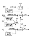
本実施の形態の制御装置は、図1のブロック図にて示すように構成されている。図1では制御装置の各要素をブロックで示し、ブロック間の信号の伝達(主なもの)を矢印で示している。以下、図1を参照して本実施の形態の制御装置の全体の構成と、その特徴について説明する。 The control device of the present embodiment is configured as shown in the block diagram of FIG. In FIG. 1, each element of the control device is indicated by a block, and signal transmission (main) between the blocks is indicated by an arrow. Hereinafter, the overall configuration and characteristics of the control apparatus of the present embodiment will be described with reference to FIG.
本実施の形態の制御装置は、内燃機関に要求されるトルクを取得する要求トルク取得部2と、内燃機関に要求される効率を取得する要求効率取得部4と、内燃機関に要求されるA/Fを取得する要求A/F取得部6とを備えている。各要求は車両の駆動系全体を制御する上位の制御装置から発せられている。
The control apparatus of the present embodiment includes a required
本実施の形態の制御装置は、入力された各機関要求(要求トルク、要求効率及び要求A/F)と、内燃機関の現在の運転状態に関する機関情報とに基づいて目標スロットル開度、目標点火時期及び目標A/Fを算出する。その計算を行うのがトルク実現部10である。トルク実現部10は内燃機関の逆モデルにあたり、マップや関数で表された複数の統計モデルや物理モデルで構成されている。内燃機関の逆モデルの構成は、制御装置による内燃機関の制御特性を特徴付けるが、本実施の形態では要求トルク、要求効率及び要求A/Fのうち、要求トルクを最優先して実現するような構成とされている。
The control device according to the present embodiment is configured so that the target throttle opening degree and the target ignition are based on each input engine request (requested torque, required efficiency and required A / F) and engine information on the current operating state of the internal combustion engine. Time and target A / F are calculated. The
トルク実現部10に入力される要求トルクと要求効率とは、直接には目標スロットル開度の計算に用いられる信号となる。また、トルク実現部10に入力される要求A/Fは、直接には目標A/Fの計算に用いられる信号となる。内燃機関の動作を制御するためには、これらの信号に加えて目標点火時期の計算に用いる信号が必要であり、トルク実現部10にはその信号を生成する機能も備えられている。
The required torque and the required efficiency that are input to the
本実施の形態の制御装置において目標点火時期の計算に用いられる信号はトルク効率である。トルク効率は、内燃機関の推定トルクに対する要求トルクの比として定義される。トルク実現部10は、トルク効率の算出ための要素として、推定トルク算出部112及びトルク効率算出部114を備えている。
The signal used for calculation of the target ignition timing in the control device of the present embodiment is torque efficiency. Torque efficiency is defined as the ratio of the required torque to the estimated torque of the internal combustion engine. The
推定トルク算出部112は、現在のスロットル開度から内燃機関のトルクを推定計算する。より詳しくは、現在のスロットル開度で実現できる吸入空気量を吸気系の物理モデルであるエアモデルを用いて計算する。次に、エアモデルで計算した見込みの吸入空気量をトルクマップに照合してトルクに変換する。トルクマップは、トルクと吸入空気量との関係を示す統計モデルであり、吸入空気量を含む複数のパラメータを軸とする多次元マップになっている。各パラメータには現在の機関情報から得られる値が入力される。ただし、点火時期は最適点火時期(MBTとトレースノック点火時期のうちより遅角側の点火時期)とされている。推定トルク算出部112は、見込みの吸入空気量から変換されたトルクを内燃機関の最適点火時期における推定トルクとして算出する。
The estimated
トルク効率算出部114は、トルク実現部10に入力された要求トルクと、推定トルク算出部112で算出された推定トルクとの比をトルク効率として算出する。後述するが、スロットル開度は要求トルクを要求効率で除算して嵩上げした補正要求トルクを実現するように制御される。これは要求効率の分だけ低下するトルクを吸入空気量の増量によって補うためである。ただし、スロットル開度の変化に対する実際の吸入空気量の応答には遅れがあるため、実際に出力可能なトルク(推定トルク)は要求効率の変化に対して応答遅れを有している。推定トルクと要求トルクとの比であるトルク効率は、要求効率と実際の吸入空気量の変化とを共に目標点火時期の計算に反映させるためのパラメータになっている。少なくとも吸入空気量が一定となった定常状態では、理論的には推定トルクは補正要求トルクに一致し、トルク効率は要求効率に一致するようになる。
The torque
ところで、車両駆動系の上位制御装置から内燃機関に発せられる要求トルク、要求効率及び要求A/Fは、各々が独立して生成されるものであって他機関要求との関係で実現可能な値かどうかは考慮されていない。このため、各機関要求の大きさの関係によっては筒内の燃焼条件が燃焼限界を超えてしまう可能性がある。そこで、トルク実現部10には、内燃機関の適正運転が可能になるように、内燃機関の各制御に用いられる信号の大きさを修正する修正部20が設けられている。修正部20の構成とその機能に関しては追って詳細に説明する。
By the way, the required torque, the required efficiency, and the required A / F issued from the host control system of the vehicle drive system to the internal combustion engine are generated independently of each other and can be realized in relation to other engine requirements. Whether or not is considered. For this reason, there is a possibility that the in-cylinder combustion conditions may exceed the combustion limit depending on the relationship between the magnitudes of the engine requirements. Therefore, the
修正部20による処理の結果、アクチュエータを制御するための各目標値の計算に使用される主信号は、修正後の要求トルク、要求効率、要求A/F及びトルク効率となる。トルク実現部10は、修正後の要求トルク及び要求効率に基づいて目標スロットル開度を算出する。また。トルク実現部10は、修正後のトルク効率に基づいて目標点火時期を算出する。また、トルク実現部10は、修正後の要求A/Fを目標A/Fとして算出する。
As a result of the processing by the
トルク実現部10は、目標スロットル開度の計算のため、要求トルク補正部102、吸入空気量算出部104及びスロットル開度算出部106を備えている。修正後の要求トルクと要求効率とは、要求トルク補正部102に入力される。要求トルク補正部102は要求トルクを要求効率で除算して補正し、効率補正後の要求トルクを目標空気量算出部104に出力する。修正後の要求効率の値が1よりも小さければ、要求効率による除算によって要求トルクは嵩上げされ、嵩上げされた要求トルクが吸入空気量算出部104に供給される。
The
吸入空気量算出部104は、効率補正された要求トルクを吸入空気量に変換する。要求トルクの吸入空気量への変換には空気量マップが用いられる。空気量マップは、トルクと吸入空気量との関係を示す統計モデルであり、トルクを含む複数のパラメータを軸とする多次元マップになっている。各パラメータには現在の機関情報から得られる値が入力される。ただし、点火時期は最適点火時期とされている。吸入空気量算出部104は、効率補正された要求トルクから変換された吸入空気量を目標吸入空気量として算出する。
The intake air
スロットル開度算出部106は、目標吸入空気量を実現するためのスロットル開度を算出する。その計算にはエアモデルの逆モデル(以下、エア逆モデル)が用いられる。エアモデルによる計算には、機関回転数やバルブタイミング等の吸入空気量に影響する各種の運転状態に関する機関情報が用いられる。スロットル開度算出部106は、目標吸入空気量から変換されたスロットル開度を目標スロットル開度として出力する。
The throttle
トルク実現部10は、修正後のトルク効率から目標点火時期を計算するため、点火時期算出部116を備えている。点火時期算出部116は、修正後のトルク効率から最適点火時期に対する遅角量を計算する。遅角量の計算にはマップ等の統計モデルが用いられる。トルク効率が小さいほど点火遅角量は大きい値に設定される。また、点火時期算出部116は、内燃機関の運転状態に基づいて最適点火時期を計算する。点火時期算出部116は、点火遅角量を最適点火時期に加算し、得られた最終的な点火時期を目標点火時期として出力する。
The
以上がトルク実現部10の基本的な構成に関する説明である。次に、本実施の形態の制御装置にとっての要部である修正部20の構成とその機能について説明する。
This completes the description of the basic configuration of the
修正部20は、要求トルク、要求効率、要求A/F及びトルク効率のそれぞれについて、その値を所定範囲に制限するためのガード部202,212,232,214を備えている。要求トルク、要求効率、要求A/F及びトルク効率は、何れもトルク実現部10の内部で使用される中間変数である点で共通している。各ガード部202,212,232,214に設定されているガード値は可変であり、内燃運転状態に応じて適宜の値がセットされる。
The
要求トルクガード部202にセットされるガード値は、トルク限界値マップ204から読み込まれる。トルク限界値マップ204には、燃焼限界に対応するトルクの値が機関回転数等に関連付けて記憶されている。また、要求A/Fガード部232にセットされるガード値は、A/F限界値マップ234から読み込まれる。A/F限界値マップ232には、燃焼限界に対応するA/Fの値が機関回転、要求トルク、要求効率等に関連付けて記憶されている。
The guard value set in the required
要求効率ガード部212とトルク効率ガード部214とには、同一のガード値がセットされる。修正部20は、これらのガード部212,214のために、ガード値の設定に用いる効率限界値マップを2種類用意している。2つの効率限界値マップ218,220は、効率のガード値が機関回転数等に関連付けて記憶されている点では共通するが、2つの効率限界値マップ218,220の間にはガード値の設定に差が設けられている。
The same guard value is set in the required
図2は2つの効率限界値マップ218,220を比較して示す図である。図2では効率のガード値(下限値)と機関回転数との関係について示している。図2において、同一の機関回転数で比較した場合、より高いガード値、すなわち、より厳しいガード値をとるのが第1の効率限界値マップ218である。第1の効率限界値マップ218では、ドラビリ限界に対応する効率の値がガード値として設定されている。ドラビリ限界とは効率の値がそれ以上であれば良好なドライバビリティを維持することが可能であって、長時間使用しても内燃機関の耐久性に影響を与えることがない限界値である。ドラビリ限界は理論上の燃焼限界に対応している。以下、ドラビリ限界を長時間限界という。
FIG. 2 is a diagram showing two efficiency limit value maps 218 and 220 in comparison. FIG. 2 shows the relationship between the efficiency guard value (lower limit value) and the engine speed. In FIG. 2, when compared at the same engine speed, the first efficiency
これに対して、同一の機関回転数で比較した場合、より低いガード値、すなわち、より緩いガード値をとるのが第2の効率限界値マップ220である。この効率限界値マップ220では、理論上の燃焼限界を超えたOT限界に対応する効率の値がガード値として設定されている。OT限界とは、長時間使用すると過熱によって内燃機関の耐久性に支障をきたしてしまうものの、短時間(例えば500msec程度)であるならば使用が可能な限界値である。以下、OT限界を短時間限界という。
On the other hand, when compared at the same engine speed, the second efficiency
修正部20は、使用する効率限界値マップ218,220を選択するための選択部216と、選択部216に対して選択の切り替えを指示する切り替え指示部222とを備えている。選択部216は、切り替え指示部222からの指示に従って2つの効率限界値マップ218,220の何れか一方を選択する。要求効率ガード部212及びトルク効率ガード部214には、選択部216によって選択されたマップから読み込まれたガード値がセットされる。
The
切り替え指示部222は、次のような切り替え規則にしたがって選択の切り替えを指示する。まず、選択部216による基本の選択は、第1の効率限界値マップ218とされている。つまり、基本的には、長時間限界に対応する厳しいガード値によって、要求効率及びトルク効率の各制限が行なわれるようになっている。
The switching
第1の効率限界値マップ218から第2の効率限界値マップ220への選択の切り替えは、次のいずれかの切替条件が成立した場合にのみ行なわれる。
(1)要求トルクの所定時間あたりの変化量が所定の切替基準量を超えていること。
(2)要求効率の所定時間あたりの変化量が所定の切替基準量を超えていること。
つまり、トルクや効率を速く或いは大きく変化させたいという要求がある場合に、長時間限界に対応する厳しいガード値から短時間限界に対応する緩いガード値への切り替えが行なわれる。この場合、切り替えの判定に必要な情報は要求トルクと要求効率のみであるので、トルク実現部10の外部から切り替えのための指示情報を供給する必要はない。
The selection switching from the first efficiency
(1) The amount of change in required torque per predetermined time exceeds a predetermined switching reference amount.
(2) The amount of change in required efficiency per predetermined time exceeds a predetermined switching reference amount.
That is, when there is a request to change torque or efficiency quickly or greatly, switching from a strict guard value corresponding to the long-time limit to a loose guard value corresponding to the short-time limit is performed. In this case, since only the required torque and the required efficiency are necessary for the determination of switching, it is not necessary to supply the instruction information for switching from the outside of the
そして、第2の効率限界値マップ220への切り替え後、所定時間が経過した時点で、再び第1の効率限界値マップ218への切り替えが行なわれる。前記の所定時間は、短時間限界に対応するガード値を連続使用することが可能な時間である。緩いガード値が選択されているときには、その間に筒内の燃焼条件が一時的に燃焼限界を超えてしまう可能性があるが、連続使用可能時間を越える前に再び厳しいガード値に切り替えられることで、内燃機関に無理が生じることを防止することができる。また、この場合も、トルク実現部10の外部から切り替えのための指示情報を供給する必要はない。
Then, when the predetermined time has elapsed after switching to the second efficiency
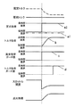
以上のような切り替え規則に従って切り替え指示部222が動作した結果の一例を図3に示す。図3には、その最上段から順に、要求トルク、要求効率、トルク効率、効率ガード値、スロットル開度、点火時期の各時間変化を示している。また、図3には(A)と(B)の二例を示している。
An example of the result of the switching
まず、(A)の例について説明すると、この例では、トルク実現部10に入力される要求トルクが急激に低下したときの動作を示している。要求効率には変化は無い。要求トルクが急低下することで前述の切替条件が成立する。これにより、要求効率ガード部212及びトルク効率ガード部214にセットされる効率ガード値は、長時間限界に対応する厳しいガード値から短時間限界に対応する緩いガード値に切り替えられる。
First, the example of (A) will be described. In this example, the operation when the required torque input to the
また、要求トルクの変化を実現するようにスロットル開度が変化するが、吸入空気量はスロットル開度の変化に遅れて変化する。このため、吸入空気量から算出される推定トルクと要求トルクとの比であるトルク効率は、要求トルクの急低下に合わせて一時的に急低下することになる。 In addition, the throttle opening changes so as to realize a change in the required torque, but the intake air amount changes behind the change in the throttle opening. For this reason, the torque efficiency, which is the ratio between the estimated torque calculated from the intake air amount and the required torque, suddenly decreases as the required torque decreases rapidly.
このとき、もし、トルク効率ガード部214の効率ガード値が長時間限界に対応する厳しいガード値になっていれば、トルク効率の急低下は効率ガード値によって制限されることになる。その場合には、点火時期の遅角量が不十分になって実際のトルクを要求トルクどおりに下げることができなくなる。
At this time, if the efficiency guard value of the torque
この点に関して本実施の形態では、前述のように、トルク効率ガード部214の効率ガード値は、要求トルクの急低下に合わせて短時間限界に対応する緩いガード値に切り替えられている。このため、トルク効率の値が効率ガード値によって制限されることはなく、要求トルクと推定トルクとのトルク差を補償するように点火時期を十分に遅角させることが可能になる。
In this regard, in the present embodiment, as described above, the efficiency guard value of the torque
その後、効率ガード値が短時間限界に対応する緩いガード値に切り替えられてから所定時間(ここでは500msec)が経過した時点で、効率ガード値は再び長時間限界に対応する厳しいガード値に切り替えられる。 Thereafter, when a predetermined time (500 msec in this case) has elapsed since the efficiency guard value was switched to a loose guard value corresponding to the short-time limit, the efficiency guard value is switched again to a strict guard value corresponding to the long-time limit. .
次に、(B)の例について説明すると、この例では、トルク実現部10に入力される要求トルクと要求効率とがともに一時的に急激に低下したときの動作を示している。要求トルクと要求効率とがともに急低下することで前述の切替条件が成立する。これにより、要求効率ガード部212及びトルク効率ガード部214にセットされる効率ガード値は、長時間限界に対応する厳しいガード値から短時間限界に対応する緩いガード値に切り替えられる。
Next, the example of (B) will be described. In this example, the operation when both the required torque and the required efficiency that are input to the
ここでは、要求トルクの低下に合わせて要求効率も低下させることで、目標吸入空気量の算出の基礎となる効率補正後の要求トルクを一定に保っている。その結果、要求トルクの変化の前後において目標吸入空気量は一定となり、スロットル開度は一定に保たれることになる。また、この場合、スロットル開度から算出される推定トルクも一定になることから、推定トルクと要求トルクとの比であるトルク効率は、要求トルクの変化に合わせて変化することになる。 Here, the required efficiency after the efficiency correction, which is the basis for calculating the target intake air amount, is kept constant by reducing the required efficiency as the required torque decreases. As a result, the target intake air amount is constant before and after the change in the required torque, and the throttle opening is kept constant. In this case, since the estimated torque calculated from the throttle opening is also constant, the torque efficiency, which is the ratio between the estimated torque and the required torque, changes in accordance with the change in the required torque.
ここで、もし、要求効率ガード部212の効率ガード値が長時間限界に対応する厳しいガード値のままであると、要求効率の急低下は効率ガード値によって制限されることになる。その場合、要求効率による要求トルクの嵩上げが不十分になって、要求トルクの変化の前後において目標吸入空気量は一時的に減少し、それに応じてスロットル開度も一時的に閉じ側に変化することになる。スロットル開度が一時的に閉じ側に変化することで、それに基づき算出される推定トルクも一時的に減少することになる。その結果、推定トルクと要求トルクとの比であるトルク効率の減少側への変化は小さくなり、トルク効率に応じて算出される点火遅角量は小さくなる。つまり、実際の効率を要求通りに下げることができなくなる。
Here, if the efficiency guard value of the required
一方、トルク効率ガード部214の効率ガード値が長時間限界に対応する厳しいガード値のままであると、トルク効率の減少側への変化は効率ガード値によって制限されることになる。その場合には、点火時期の遅角量が不十分になって実際のトルクを要求トルクどおりに下げることができなくなってしまう。
On the other hand, if the efficiency guard value of the torque
これらの点に関して本実施の形態では、前述のように、要求効率ガード部212及びトルク効率ガード部214の効率ガード値は、要求トルク及び要求効率の一時的な低下に合わせて短時間限界に対応する緩いガード値に一時的に切り替えられる。このため、要求トルクとトルク効率の何れの値も効率ガード値によって制限されることはなく、要求通りのトルクと効率とを内燃機関に実現させることが可能になる。
With regard to these points, in the present embodiment, as described above, the efficiency guard values of the required
この例でも、効率ガード値が短時間限界に対応する緩いガード値に切り替えられてから所定時間が経過した時点で、効率ガード値は再び長時間限界に対応する厳しいガード値に切り替えられる。 Also in this example, the efficiency guard value is switched again to a strict guard value corresponding to the long-time limit when a predetermined time elapses after the efficiency guard value is switched to the loose guard value corresponding to the short-time limit.
上述のような構成及び機能を有する修正部20によれば、要求トルク、要求効率、要求A/F及びトルク効率のそれぞれに対してガード部202,212,232,214が設けられることで、入力される要求トルク、要求効率及び要求A/Fの各値がどのようであっても、筒内の燃焼条件は燃焼限界内に収めることができる。また、要求効率及びトルク効率を制限するガード値は要求トルクや要求効率の時間変化量の大きさに応じて自動的に緩和されるので、トルクや効率を速く或いは大きく変化させたいという要求がある場合には、その要求通りの時間変化或いは要求に可能な限り近い時間変化を実現することができる。
According to the
以上、本発明の実施の形態1について説明した。実施の形態1には、本発明のうち第1、第2及び第3の発明が具現化されている。詳しくは、図1に示す構成において、要求トルク取得部2、要求効率取得部4及び要求A/F取得部6は第1の発明の「要求取得手段」に相当し、要求トルク、要求効率及び要求A/Fは「機関要求」に該当する。トルク実現部10は第1の発明の「目標値算出手段」に相当する。また、要求効率ガード部212及びトルク効率ガード部214と2つの効率限界マップ218,220とにより第1及び第2の発明の「ガード手段」が構成され、要求効率及びトルク効率は「所定の中間変数」に該当する。また、選択部216及び切り替え指示部222により第1,第2及び第3の発明の「ガード緩和手段」が構成されている。
The first embodiment of the present invention has been described above. The first embodiment embodies the first, second and third aspects of the present invention. Specifically, in the configuration shown in FIG. 1, the required
実施の形態2.
次に、本発明の実施の形態2について図1、図4及び図5を用いて説明する。
Next, a second embodiment of the present invention will be described with reference to FIGS.
本実施の形態の制御装置の全体の構成は、実施の形態1と同じく、図1のブロック図にて示される。ただし、本実施の形態の制御装置と実施の形態1の制御装置とは、制御装置を構成する一要素である修正部20の構成に違いが有る。本実施の形態にかかる修正部20の要部の構成を示したのが図4のブロック図である。つまり、本実施の形態の制御装置の構成は、図1に示す構成の一部を図4に示す構成に置き換えたものになっている。以下、図1とともに図4を参照して本実施の形態の特徴である修正部20の構成について説明する。
The overall configuration of the control device of the present embodiment is shown in the block diagram of FIG. However, the control device according to the present embodiment and the control device according to the first embodiment are different in the configuration of the
本実施の形態にかかる修正部20は、トルク効率の値を制限するためのガード部を備えていない。一方、要求効率の値を制限するための要求効率ガード部212は備えられている。切り替え指示部222からの指示に従って2つの効率限界値マップ218,220の何れか一方が選択部216によって選択され、選択されたマップから読み込まれた効率ガード値が要求効率ガード部212にセットされる。
The
図4に示す構成によれば、目標スロットル開度の算出に使用する要求効率にのみガード部212が設けられることで、ガード値の切り替えのための複雑なロジックが不要になるという利点がある。また、目標点火時期の算出に使用するトルク効率には制限を設けないことで、点火時期の設定可能範囲を広く取ることができ、要求トルクの変化に対する高いトルク応答性を実現することができるという利点もある。
According to the configuration shown in FIG. 4, the
図5は、本実施の形態にかかる修正部20において、切り替え指示部222が動作した結果の一例を示した図である。なお、切り替え指示部222が従う切り替え規則は、実施の形態1で説明した通りである。図5には、その最上段から順に、推定トルク及び要求トルク、要求効率、要求効率ガード値、スロットル開度、点火時期の各時間変化を示している。
FIG. 5 is a diagram illustrating an example of a result of the switching
図5に示す例では、要求効率ガード部212の効率ガード値が短時間限界に対応する緩いガード値から長時間限界に対応する厳しいガード値に切り替えられたときの動作を示している。ここでは、要求効率ガード部212に入力される要求効率の値a1は短時間限界に対応する効率ガード値よりも低くなっているとする。この場合、効率ガード値が切り替えられる以前は、短時間限界に対応する効率ガード値が要求効率ガード部212から出力される要求効率の値a2となる。そして、効率ガード値が切り替えられた後は、長時間限界に対応する効率ガード値が要求効率ガード部212から出力される要求効率の値a2となる。つまり、効率ガード値が切り替えられる前後において要求効率の値a2は急変する。要求効率の値a2の急変は、要求効率を用いて算出される目標スロットル開度に反映され、さらには、スロットル開度に基づいて算出される推定トルクの値に反映される。推定トルクが変化することで、推定トルクと要求トルクとの比であるトルク効率も変化することになる。
The example shown in FIG. 5 shows an operation when the efficiency guard value of the required
このとき、もし、要求効率に掛けられているのと同じ効率ガード値がトルク効率にも掛けられているならば、効率ガード値が長時間限界に対応する厳しいガード値に切り替えられた時点で、トルク効率の値は急増することになる。トルク効率が急増すれば点火時期は急に進角されることになり、しかも点火時期はトルク応答性に優れているので、突然のトルクの増大によってトルク段差が発生してしまう。 At this time, if the same efficiency guard value multiplied by the required efficiency is also multiplied by the torque efficiency, when the efficiency guard value is switched to a strict guard value corresponding to the long-time limit, The value of torque efficiency will increase rapidly. If the torque efficiency increases rapidly, the ignition timing is suddenly advanced, and the ignition timing is excellent in torque response, so that a torque step occurs due to a sudden increase in torque.
この点に関して本実施の形態では、前述のように、効率ガード値によるトルク効率の値の制限は行なわれない。したがって、効率ガード値が切り替えられた前後においてトルク効率の値が急変することはない。この場合、トルク効率は推定トルクの低下に伴って増大し、点火時期は推定トルクと要求トルクとの差の縮小に合わせて進角側に戻されていく。 In this regard, in the present embodiment, as described above, the torque efficiency value is not limited by the efficiency guard value. Therefore, the torque efficiency value does not change suddenly before and after the efficiency guard value is switched. In this case, the torque efficiency increases as the estimated torque decreases, and the ignition timing is returned to the advance side as the difference between the estimated torque and the required torque decreases.
以上、本発明の実施の形態2について説明した。実施の形態2には、本発明のうち第1、第2、第3及び第4の発明が具現化されている。詳しくは、図1に示す構成において、要求トルク取得部2及び要求効率取得部4は第4の発明の「要求取得手段」に相当し、トルク実現部10は第4の発明の「目標値算出手段」に相当する。また、図4に示す構成において、要求効率ガード部212と2つの効率限界マップ218,220とにより第4の発明の「ガード手段」が構成されている。また、選択部216及び切り替え指示部222により第4の発明の「ガード緩和手段」が構成されている。なお、実施の形態2の第1、第2及び第3の発明との対応関係については実施の形態1のそれと同じである。
The second embodiment of the present invention has been described above. The second embodiment embodies the first, second, third and fourth aspects of the present invention. Specifically, in the configuration shown in FIG. 1, the required
実施の形態3.
次に、本発明の実施の形態3について図1、図6及び図7を用いて説明する。
Embodiment 3 FIG.
Next, Embodiment 3 of the present invention will be described with reference to FIG. 1, FIG. 6, and FIG.
本実施の形態の制御装置の全体の構成は、実施の形態1と同じく、図1のブロック図にて示される。ただし、本実施の形態の制御装置と実施の形態1の制御装置とは、制御装置を構成する一要素である修正部20の構成に違いが有る。本実施の形態にかかる修正部20の要部の構成を示したのが図6のブロック図である。つまり、本実施の形態の制御装置の構成は、図1に示す構成の一部を図6に示す構成に置き換えたものになっている。以下、図1とともに図6を参照して本実施の形態の特徴である修正部20の構成について説明する。
The overall configuration of the control device of the present embodiment is shown in the block diagram of FIG. However, the control device according to the present embodiment and the control device according to the first embodiment are different in the configuration of the
本実施の形態にかかる修正部20は、要求効率の値を制限するための要求効率ガード部212と、トルク効率の値を制限するためのトルク効率ガード部214とを備えている点では実施の形態1と共通する。ただし、これらのガード部212,214にガード値を設定する選択部216の機能に違いがある。
The
本実施の形態にかかる選択部216は、要求効率ガード部212の効率ガード値を短時間限界に対応する緩いガード値から長時間限界に対応する厳しいガード値に切り替えた後、所定時間が経過してから、トルク効率ガード部214の効率ガード値を短時間限界に対応する緩いガード値から長時間限界に対応する厳しいガード値に切り替える。つまり、要求効率ガード部212とトルク効率ガード部214との間で、緩いガード値から厳しいガード値への切り替えに時間差を設けている。切り替えのための時間差は、要求トルクに対する推定トルクの応答遅れ時間に合わせて設定されている。
The
本実施の形態を実施の形態2と比較した場合、本実施の形態には次のような利点がある。実施の形態2によれば、目標点火時期の算出に使用するトルク効率には効率ガード値による制限を施さないことで、効率ガード値の切り替えにともなうトルク段差の発生を防止することができる。しかし、トルク効率の値が燃焼限界を超えた状態を許容することになるため、場合によっては内燃機関に無理が生じてしまう可能性がある。これに対して本実施の形態によれば、トルク効率にも効率ガード値による制限が施されることで、トルク効率の値が長時間にわたって燃焼限界を超えることは防止される。さらに、トルク効率ガード部214の効率ガード値が切り替えられるのは、要求効率ガード部212の効率ガード値が切り替えられた後であるので、その時間差内においてトルク効率は要求効率に追従して変化する。これにより、効率ガード値が切り替えられた時点においては、トルク効率の値と切り替え後の厳しいガード値との差は縮小されており、切り替えにともなうトルク段差の発生は抑えられる。
When this embodiment is compared with the second embodiment, this embodiment has the following advantages. According to the second embodiment, the torque efficiency used for calculating the target ignition timing is not limited by the efficiency guard value, so that it is possible to prevent the occurrence of a torque step associated with the switching of the efficiency guard value. However, since the torque efficiency value is allowed to exceed the combustion limit, in some cases, the internal combustion engine may become unreasonable. On the other hand, according to the present embodiment, the torque efficiency is also limited by the efficiency guard value, so that the torque efficiency value is prevented from exceeding the combustion limit for a long time. Further, since the efficiency guard value of the torque
図7は、本実施の形態にかかる修正部20において、切り替え指示部222が動作した結果の一例を示した図である。なお、切り替え指示部222が従う切り替え規則は、実施の形態1で説明した通りである。図7には、その最上段から順に、推定トルク及び要求トルク、要求効率、トルク効率、要求効率ガード値、トルク効率ガード値、スロットル開度、点火時期の各時間変化を示している。
FIG. 7 is a diagram illustrating an example of a result of the switching
図7に示す例では、要求効率ガード部212の効率ガード値cが短時間限界に対応する緩いガード値から長時間限界に対応する厳しいガード値に切り替えられたときの動作を示している。ここでは、要求効率ガード部212に入力される要求効率の値a1は短時間限界に対応する効率ガード値cよりも低いとする。この場合、効率ガード値cが切り替えられる以前は、短時間限界に対応する効率ガード値が要求効率ガード部212から出力される要求効率の値a2となる。そして、効率ガード値が切り替えられた後は、長時間限界に対応する効率ガード値が要求効率ガード部212から出力される要求効率の値a2となる。つまり、効率ガード値cが切り替えられる前後において要求効率の値a2は急変する。
The example shown in FIG. 7 shows an operation when the efficiency guard value c of the required
要求効率の値a2の急変は、要求効率を用いて算出される目標スロットル開度に反映され、さらには、スロットル開度に基づいて算出される推定トルクの値に反映される。推定トルクが変化することで、推定トルクと要求トルクとの比であるトルク効率bも変化することになる。トルク効率bは要求効率に追従して変化し、やがて、長時間限界に対応する効率ガード値に収束する。 The sudden change in the required efficiency value a2 is reflected in the target throttle opening calculated using the required efficiency, and further reflected in the estimated torque value calculated based on the throttle opening. As the estimated torque changes, the torque efficiency b, which is the ratio between the estimated torque and the required torque, also changes. The torque efficiency b changes following the required efficiency and eventually converges to an efficiency guard value corresponding to the long-time limit.
要求効率ガード部212の効率ガード値cが切り替えられた後、所定時間が経過した時点で、トルク効率ガード部214の効率ガード値dが短時間限界に対応する緩いガード値から長時間限界に対応する厳しいガード値に切り替えられる。要求トルクに対する推定トルクの応答遅れ時間に合わせて切り替えの時間差が設けられているので、この時点でのトルク効率bは略長時間限界に対応する効率ガード値に収束している。したがって、効率ガード値dの切り替えによって発生するトルク段差は無いか、或いは極めて小さいものに抑えられている。
When a predetermined time elapses after the efficiency guard value c of the required
以上、本発明の実施の形態3について説明した。実施の形態3には、本発明のうち第1、第2、第3、第4及び第5の発明が具現化されている。詳しくは、図6に示す構成において、要求効率ガード部212及びトルク効率ガード部214と2つの効率限界マップ218,220とにより第5の発明の「ガード手段」が構成されている。また、選択部216及び切り替え指示部222により第5の発明の「ガード緩和手段」が構成されている。なお、実施の形態3の第1、第2、第3及び第4の発明との対応関係については実施の形態1のそれと同じである。
The third embodiment of the present invention has been described above. The third embodiment embodies the first, second, third, fourth, and fifth inventions of the present invention. Specifically, in the configuration shown in FIG. 6, the required
その他.
本発明は上述の実施の形態に限定されるものではなく、本発明の趣旨を逸脱しない範囲で種々変形して実施することができる。例えば、上述の実施の形態では、吸入空気量を調整する吸気量調整弁としてスロットル弁を用いているが、可変動弁機構付の吸気弁を用いてもよい。その場合の吸気量調整弁の目標弁開度とは、吸気弁のリフト量或いは作用角の目標値である。
Others.
The present invention is not limited to the above-described embodiment, and various modifications can be made without departing from the spirit of the present invention. For example, in the above-described embodiment, the throttle valve is used as the intake air amount adjustment valve for adjusting the intake air amount, but an intake valve with a variable valve mechanism may be used. In this case, the target valve opening of the intake air amount adjusting valve is a target value of the lift amount or operating angle of the intake valve.
また、上述の実施の形態では効率限界値マップを2種類用意しているが、より多くのマップを用意して要求トルクや要求効率の時間変化量に応じて切り替えるようにしてもよい。或いは、要求トルクや要求効率の時間変化量に応じてガード値を連続的に変化させるようにしてもよい。 In the above-described embodiment, two types of efficiency limit value maps are prepared. However, more maps may be prepared and switched according to the required torque and the amount of change in required efficiency over time. Or you may make it change a guard value continuously according to the amount of time change of request torque or request efficiency.
さらに、上述の実施の形態では要求効率とトルク効率の各ガード値を切り替えているが、それと併せて或いはそれに代えて、要求A/Fのガード値を切り替えるようにしてもよい。また、要求効率やトルク効率或いは要求A/F以外の中間変数にガードを設けて、そのガード値を機関要求値の時間変化量に応じて緩和させるようにしてもよい。 Further, in the above-described embodiment, the guard values for the required efficiency and the torque efficiency are switched, but the guard values for the required A / F may be switched in addition to or instead of the guard values. Further, a guard may be provided in an intermediate variable other than the required efficiency, torque efficiency, or required A / F, and the guard value may be relaxed according to the time change amount of the engine required value.
2 要求トルク取得部
4 要求効率取得部
6 要求A/F取得部
10 トルク実現部
20 修正部
102 要求トルク補正部
104 吸入空気量算出部
106 スロットル開度算出部
112 推定トルク算出部
114 トルク効率算出部
116 点火時期算出部
202 要求トルクガード部
204 トルク限界値マップ
212 要求効率ガード部
214 トルク効率ガード部
216 選択部
218 効率限界値マップ(長時間限界)
220 効率限界値マップ(短時間限界)
222 切り替え指示部
232 要求A/Fガード部
234 A/F限界値マップ
2 required
220 Efficiency limit value map (short time limit)
222
Claims (5)
前記内燃機関の動作を決定する複数の所定物理量に関する要求(以下、機関要求)を取得する要求取得手段と、
取得した各機関要求と前記内燃機関の現在の運転状態とに基づいて、取得した各機関要求が前記内燃機関で実現されるための目標弁開度及び目標点火時期を算出する目標値算出手段と、
目標弁開度及び目標点火時期によって決まる筒内の燃焼条件が燃焼限界内に収まるように、各機関要求から目標弁開度或いは目標点火時期が算出される過程で用いられる所定の中間変数の値に制限を設けるガード手段と、
少なくも1つの機関要求についてその時間変化量を計算し、算出した時間変化量の大きさに応じて前記ガード手段による制限を緩和させるガード緩和手段と、
を備えることを特徴とする内燃機関の制御装置。 In a control device for an internal combustion engine, the operation of which is controlled by the opening and ignition timing of an intake air amount adjustment valve that adjusts the intake air amount.
Request acquisition means for acquiring a plurality of predetermined physical quantity requests (hereinafter referred to as engine requests) for determining the operation of the internal combustion engine;
Target value calculating means for calculating a target valve opening and a target ignition timing for realizing each acquired engine request in the internal combustion engine based on each acquired engine request and the current operating state of the internal combustion engine; ,
The value of a predetermined intermediate variable used in the process of calculating the target valve opening or target ignition timing from each engine request so that the in-cylinder combustion conditions determined by the target valve opening and target ignition timing are within the combustion limit. Guard means for limiting the
Guard relaxation means for calculating the time change amount for at least one engine request, and relaxing the restriction by the guard means according to the calculated time change amount;
A control device for an internal combustion engine, comprising:
前記ガード緩和手段は、算出した時間変化量が基準量を越えるときには、前記ガード手段に対して厳しいガード値から緩いガード値への切り替えを指示することを特徴とする請求項1記載の内燃機関の制御装置。 The guard means has a strict guard value and a loose guard value as guard values for limiting the value of the predetermined intermediate variable,
2. The internal combustion engine according to claim 1, wherein the guard relaxation means instructs the guard means to switch from a strict guard value to a loose guard value when the calculated time change amount exceeds a reference amount. Control device.
前記目標値算出手段は、取得した要求トルクと要求効率とから目標弁開度を算出するとともに、要求トルクと現在の弁開度から推定されるトルクとの比であるトルク効率に基づいて目標点火時期を算出し、
前記ガード手段は、目標弁開度の算出に使用する要求効率を前記所定中間変数としてその値に制限を設けていて、
前記ガード緩和手段は、前記要求取得手段によって取得された要求トルク或いは要求効率の時間変化量の大きさに応じて前記ガード手段による制限を緩和させることを特徴とする請求項3記載の内燃機関の制御装置。 The request acquisition means acquires a required torque and a required efficiency as an engine request,
The target value calculating means calculates a target valve opening from the acquired required torque and required efficiency, and also performs target ignition based on a torque efficiency that is a ratio of the required torque and a torque estimated from the current valve opening. Calculate the time,
The guard means provides a restriction on the value of the required efficiency used to calculate the target valve opening as the predetermined intermediate variable,
4. The internal combustion engine according to claim 3, wherein the guard relaxation means relaxes the restriction by the guard means according to the amount of time change in the required torque or the required efficiency acquired by the request acquisition means. Control device.
前記ガード緩和手段は、要求効率のガード値が緩いガード値から厳しいガード値へ切り替えられてから所定時間が経過した後、前記ガード手段に対してトルク効率のガード値を緩いガード値から厳しいガード値へ切り替えるよう指示することを特徴とする請求項4記載の内燃機関の制御装置。 The guard means is provided with a restriction on each value as a predetermined intermediate variable, the required efficiency used for calculating the target valve opening and the torque efficiency used for calculating the target ignition timing,
The guard relaxation means changes the guard efficiency value of the torque efficiency from a loose guard value to a severe guard value after a predetermined time has elapsed since the guard value of the required efficiency has been switched from a loose guard value to a severe guard value. 5. The control apparatus for an internal combustion engine according to claim 4, wherein an instruction to switch to is issued.
Priority Applications (1)
| Application Number | Priority Date | Filing Date | Title |
|---|---|---|---|
| JP2008221847A JP5125896B2 (en) | 2008-08-29 | 2008-08-29 | Control device for internal combustion engine |
Applications Claiming Priority (1)
| Application Number | Priority Date | Filing Date | Title |
|---|---|---|---|
| JP2008221847A JP5125896B2 (en) | 2008-08-29 | 2008-08-29 | Control device for internal combustion engine |
Publications (2)
| Publication Number | Publication Date |
|---|---|
| JP2010053826A JP2010053826A (en) | 2010-03-11 |
| JP5125896B2 true JP5125896B2 (en) | 2013-01-23 |
Family
ID=42069998
Family Applications (1)
| Application Number | Title | Priority Date | Filing Date |
|---|---|---|---|
| JP2008221847A Expired - Fee Related JP5125896B2 (en) | 2008-08-29 | 2008-08-29 | Control device for internal combustion engine |
Country Status (1)
| Country | Link |
|---|---|
| JP (1) | JP5125896B2 (en) |
Families Citing this family (4)
| Publication number | Priority date | Publication date | Assignee | Title |
|---|---|---|---|---|
| KR101080659B1 (en) * | 2008-10-31 | 2011-11-08 | 도요타 지도샤(주) | Controller for internal-combustion engine |
| JP5108799B2 (en) * | 2009-01-27 | 2012-12-26 | トヨタ自動車株式会社 | Control device for internal combustion engine |
| WO2012049729A1 (en) | 2010-10-12 | 2012-04-19 | トヨタ自動車株式会社 | Control device of internal combustion engine |
| CN102652216B (en) | 2010-10-12 | 2013-03-20 | 丰田自动车株式会社 | Control device of internal combustion engine |
Family Cites Families (8)
| Publication number | Priority date | Publication date | Assignee | Title |
|---|---|---|---|---|
| JP2591327B2 (en) * | 1990-11-02 | 1997-03-19 | 三菱自動車工業株式会社 | Engine output control device |
| JP2003159964A (en) * | 2001-11-22 | 2003-06-03 | Mazda Motor Corp | Vehicle control device |
| JP2003301766A (en) * | 2002-04-09 | 2003-10-24 | Denso Corp | Torque control device of internal combustion engine |
| JP4263466B2 (en) * | 2002-12-05 | 2009-05-13 | 本田技研工業株式会社 | Control device for internal combustion engine |
| JP4111041B2 (en) * | 2003-04-15 | 2008-07-02 | トヨタ自動車株式会社 | Air-fuel ratio control device for internal combustion engine |
| JP2006138300A (en) * | 2004-11-15 | 2006-06-01 | Denso Corp | Torque control device for internal combustion engine |
| JP2006242111A (en) * | 2005-03-04 | 2006-09-14 | Nissan Motor Co Ltd | Drive force control device for vehicle |
| JP4464932B2 (en) * | 2006-04-27 | 2010-05-19 | 日立オートモティブシステムズ株式会社 | Engine control device |
-
2008
- 2008-08-29 JP JP2008221847A patent/JP5125896B2/en not_active Expired - Fee Related
Also Published As
| Publication number | Publication date |
|---|---|
| JP2010053826A (en) | 2010-03-11 |
Similar Documents
| Publication | Publication Date | Title |
|---|---|---|
| JP4442704B2 (en) | Control device for internal combustion engine | |
| JP5195064B2 (en) | Control device for internal combustion engine | |
| JP4941193B2 (en) | Control device for internal combustion engine | |
| JP2010216419A (en) | Control device for internal combustion engine | |
| WO2011135681A1 (en) | Control device for internal combustion engine | |
| JP5125896B2 (en) | Control device for internal combustion engine | |
| JP4816813B2 (en) | Control device for internal combustion engine | |
| JP2009299667A (en) | Control device for internal combustion engine | |
| JP4941413B2 (en) | Control device for internal combustion engine | |
| JP5534098B2 (en) | Control device for internal combustion engine | |
| US8793058B2 (en) | Control device for internal combustion engine | |
| JP5189513B2 (en) | Control device for internal combustion engine | |
| JP5169934B2 (en) | Control device for internal combustion engine | |
| JP2010112214A (en) | Control device of internal combustion engine | |
| JP5108799B2 (en) | Control device for internal combustion engine | |
| JP4911145B2 (en) | Control device for internal combustion engine | |
| JP4968185B2 (en) | Control device for internal combustion engine | |
| JP2010090813A (en) | Internal combustion engine control system | |
| JP2010249018A (en) | Control device for internal combustion engine | |
| JP2010019136A (en) | Control device for internal combustion engine | |
| JP5267291B2 (en) | Control device for internal combustion engine | |
| JP4997208B2 (en) | Control device for internal combustion engine | |
| JP2010038151A (en) | Internal combustion engine control device | |
| JP5120275B2 (en) | Control device for internal combustion engine | |
| JP5540761B2 (en) | Control device for internal combustion engine |
Legal Events
| Date | Code | Title | Description |
|---|---|---|---|
| A621 | Written request for application examination |
Free format text: JAPANESE INTERMEDIATE CODE: A621 Effective date: 20110801 |
|
| A977 | Report on retrieval |
Free format text: JAPANESE INTERMEDIATE CODE: A971007 Effective date: 20120525 |
|
| A131 | Notification of reasons for refusal |
Free format text: JAPANESE INTERMEDIATE CODE: A131 Effective date: 20120605 |
|
| TRDD | Decision of grant or rejection written | ||
| A01 | Written decision to grant a patent or to grant a registration (utility model) |
Free format text: JAPANESE INTERMEDIATE CODE: A01 Effective date: 20121002 |
|
| A01 | Written decision to grant a patent or to grant a registration (utility model) |
Free format text: JAPANESE INTERMEDIATE CODE: A01 |
|
| A61 | First payment of annual fees (during grant procedure) |
Free format text: JAPANESE INTERMEDIATE CODE: A61 Effective date: 20121015 |
|
| R151 | Written notification of patent or utility model registration |
Ref document number: 5125896 Country of ref document: JP Free format text: JAPANESE INTERMEDIATE CODE: R151 |
|
| FPAY | Renewal fee payment (event date is renewal date of database) |
Free format text: PAYMENT UNTIL: 20151109 Year of fee payment: 3 |
|
| LAPS | Cancellation because of no payment of annual fees |