JP5123513B2 - Absorber - Google Patents
Absorber Download PDFInfo
- Publication number
- JP5123513B2 JP5123513B2 JP2006270112A JP2006270112A JP5123513B2 JP 5123513 B2 JP5123513 B2 JP 5123513B2 JP 2006270112 A JP2006270112 A JP 2006270112A JP 2006270112 A JP2006270112 A JP 2006270112A JP 5123513 B2 JP5123513 B2 JP 5123513B2
- Authority
- JP
- Japan
- Prior art keywords
- fiber
- fibers
- absorber
- absorbent body
- basis weight
- Prior art date
- Legal status (The legal status is an assumption and is not a legal conclusion. Google has not performed a legal analysis and makes no representation as to the accuracy of the status listed.)
- Expired - Fee Related
Links
Images


Classifications
-
- A—HUMAN NECESSITIES
- A61—MEDICAL OR VETERINARY SCIENCE; HYGIENE
- A61F—FILTERS IMPLANTABLE INTO BLOOD VESSELS; PROSTHESES; DEVICES PROVIDING PATENCY TO, OR PREVENTING COLLAPSING OF, TUBULAR STRUCTURES OF THE BODY, e.g. STENTS; ORTHOPAEDIC, NURSING OR CONTRACEPTIVE DEVICES; FOMENTATION; TREATMENT OR PROTECTION OF EYES OR EARS; BANDAGES, DRESSINGS OR ABSORBENT PADS; FIRST-AID KITS
- A61F13/00—Bandages or dressings; Absorbent pads
- A61F13/15—Absorbent pads, e.g. sanitary towels, swabs or tampons for external or internal application to the body; Supporting or fastening means therefor; Tampon applicators
- A61F13/15577—Apparatus or processes for manufacturing
- A61F13/15617—Making absorbent pads from fibres or pulverulent material with or without treatment of the fibres
- A61F13/15658—Forming continuous, e.g. composite, fibrous webs, e.g. involving the application of pulverulent material on parts thereof
-
- A—HUMAN NECESSITIES
- A61—MEDICAL OR VETERINARY SCIENCE; HYGIENE
- A61F—FILTERS IMPLANTABLE INTO BLOOD VESSELS; PROSTHESES; DEVICES PROVIDING PATENCY TO, OR PREVENTING COLLAPSING OF, TUBULAR STRUCTURES OF THE BODY, e.g. STENTS; ORTHOPAEDIC, NURSING OR CONTRACEPTIVE DEVICES; FOMENTATION; TREATMENT OR PROTECTION OF EYES OR EARS; BANDAGES, DRESSINGS OR ABSORBENT PADS; FIRST-AID KITS
- A61F13/00—Bandages or dressings; Absorbent pads
- A61F13/15—Absorbent pads, e.g. sanitary towels, swabs or tampons for external or internal application to the body; Supporting or fastening means therefor; Tampon applicators
- A61F13/15577—Apparatus or processes for manufacturing
- A61F13/15617—Making absorbent pads from fibres or pulverulent material with or without treatment of the fibres
- A61F13/15634—Making fibrous pads between sheets or webs
-
- A—HUMAN NECESSITIES
- A61—MEDICAL OR VETERINARY SCIENCE; HYGIENE
- A61F—FILTERS IMPLANTABLE INTO BLOOD VESSELS; PROSTHESES; DEVICES PROVIDING PATENCY TO, OR PREVENTING COLLAPSING OF, TUBULAR STRUCTURES OF THE BODY, e.g. STENTS; ORTHOPAEDIC, NURSING OR CONTRACEPTIVE DEVICES; FOMENTATION; TREATMENT OR PROTECTION OF EYES OR EARS; BANDAGES, DRESSINGS OR ABSORBENT PADS; FIRST-AID KITS
- A61F13/00—Bandages or dressings; Absorbent pads
- A61F13/15—Absorbent pads, e.g. sanitary towels, swabs or tampons for external or internal application to the body; Supporting or fastening means therefor; Tampon applicators
- A61F13/53—Absorbent pads, e.g. sanitary towels, swabs or tampons for external or internal application to the body; Supporting or fastening means therefor; Tampon applicators characterised by the absorbing medium
- A61F13/531—Absorbent pads, e.g. sanitary towels, swabs or tampons for external or internal application to the body; Supporting or fastening means therefor; Tampon applicators characterised by the absorbing medium having a homogeneous composition through the thickness of the pad
- A61F13/532—Absorbent pads, e.g. sanitary towels, swabs or tampons for external or internal application to the body; Supporting or fastening means therefor; Tampon applicators characterised by the absorbing medium having a homogeneous composition through the thickness of the pad inhomogeneous in the plane of the pad
- A61F13/5323—Absorbent pads, e.g. sanitary towels, swabs or tampons for external or internal application to the body; Supporting or fastening means therefor; Tampon applicators characterised by the absorbing medium having a homogeneous composition through the thickness of the pad inhomogeneous in the plane of the pad having absorbent material located in discrete regions, e.g. pockets
-
- A—HUMAN NECESSITIES
- A61—MEDICAL OR VETERINARY SCIENCE; HYGIENE
- A61F—FILTERS IMPLANTABLE INTO BLOOD VESSELS; PROSTHESES; DEVICES PROVIDING PATENCY TO, OR PREVENTING COLLAPSING OF, TUBULAR STRUCTURES OF THE BODY, e.g. STENTS; ORTHOPAEDIC, NURSING OR CONTRACEPTIVE DEVICES; FOMENTATION; TREATMENT OR PROTECTION OF EYES OR EARS; BANDAGES, DRESSINGS OR ABSORBENT PADS; FIRST-AID KITS
- A61F13/00—Bandages or dressings; Absorbent pads
- A61F13/15—Absorbent pads, e.g. sanitary towels, swabs or tampons for external or internal application to the body; Supporting or fastening means therefor; Tampon applicators
- A61F13/53—Absorbent pads, e.g. sanitary towels, swabs or tampons for external or internal application to the body; Supporting or fastening means therefor; Tampon applicators characterised by the absorbing medium
- A61F13/531—Absorbent pads, e.g. sanitary towels, swabs or tampons for external or internal application to the body; Supporting or fastening means therefor; Tampon applicators characterised by the absorbing medium having a homogeneous composition through the thickness of the pad
- A61F13/532—Absorbent pads, e.g. sanitary towels, swabs or tampons for external or internal application to the body; Supporting or fastening means therefor; Tampon applicators characterised by the absorbing medium having a homogeneous composition through the thickness of the pad inhomogeneous in the plane of the pad
- A61F13/533—Absorbent pads, e.g. sanitary towels, swabs or tampons for external or internal application to the body; Supporting or fastening means therefor; Tampon applicators characterised by the absorbing medium having a homogeneous composition through the thickness of the pad inhomogeneous in the plane of the pad having discontinuous areas of compression
-
- A—HUMAN NECESSITIES
- A61—MEDICAL OR VETERINARY SCIENCE; HYGIENE
- A61F—FILTERS IMPLANTABLE INTO BLOOD VESSELS; PROSTHESES; DEVICES PROVIDING PATENCY TO, OR PREVENTING COLLAPSING OF, TUBULAR STRUCTURES OF THE BODY, e.g. STENTS; ORTHOPAEDIC, NURSING OR CONTRACEPTIVE DEVICES; FOMENTATION; TREATMENT OR PROTECTION OF EYES OR EARS; BANDAGES, DRESSINGS OR ABSORBENT PADS; FIRST-AID KITS
- A61F13/00—Bandages or dressings; Absorbent pads
- A61F13/15—Absorbent pads, e.g. sanitary towels, swabs or tampons for external or internal application to the body; Supporting or fastening means therefor; Tampon applicators
- A61F13/53—Absorbent pads, e.g. sanitary towels, swabs or tampons for external or internal application to the body; Supporting or fastening means therefor; Tampon applicators characterised by the absorbing medium
- A61F13/534—Absorbent pads, e.g. sanitary towels, swabs or tampons for external or internal application to the body; Supporting or fastening means therefor; Tampon applicators characterised by the absorbing medium having an inhomogeneous composition through the thickness of the pad
- A61F13/535—Absorbent pads, e.g. sanitary towels, swabs or tampons for external or internal application to the body; Supporting or fastening means therefor; Tampon applicators characterised by the absorbing medium having an inhomogeneous composition through the thickness of the pad inhomogeneous in the plane of the pad, e.g. core absorbent layers being of different sizes
- A61F13/536—Absorbent pads, e.g. sanitary towels, swabs or tampons for external or internal application to the body; Supporting or fastening means therefor; Tampon applicators characterised by the absorbing medium having an inhomogeneous composition through the thickness of the pad inhomogeneous in the plane of the pad, e.g. core absorbent layers being of different sizes having discontinuous areas of compression
-
- A—HUMAN NECESSITIES
- A61—MEDICAL OR VETERINARY SCIENCE; HYGIENE
- A61F—FILTERS IMPLANTABLE INTO BLOOD VESSELS; PROSTHESES; DEVICES PROVIDING PATENCY TO, OR PREVENTING COLLAPSING OF, TUBULAR STRUCTURES OF THE BODY, e.g. STENTS; ORTHOPAEDIC, NURSING OR CONTRACEPTIVE DEVICES; FOMENTATION; TREATMENT OR PROTECTION OF EYES OR EARS; BANDAGES, DRESSINGS OR ABSORBENT PADS; FIRST-AID KITS
- A61F13/00—Bandages or dressings; Absorbent pads
- A61F13/15—Absorbent pads, e.g. sanitary towels, swabs or tampons for external or internal application to the body; Supporting or fastening means therefor; Tampon applicators
- A61F2013/15008—Absorbent pads, e.g. sanitary towels, swabs or tampons for external or internal application to the body; Supporting or fastening means therefor; Tampon applicators characterized by the use
- A61F2013/15016—Absorbent pads, e.g. sanitary towels, swabs or tampons for external or internal application to the body; Supporting or fastening means therefor; Tampon applicators characterized by the use for breast; pads for bras
-
- A—HUMAN NECESSITIES
- A61—MEDICAL OR VETERINARY SCIENCE; HYGIENE
- A61F—FILTERS IMPLANTABLE INTO BLOOD VESSELS; PROSTHESES; DEVICES PROVIDING PATENCY TO, OR PREVENTING COLLAPSING OF, TUBULAR STRUCTURES OF THE BODY, e.g. STENTS; ORTHOPAEDIC, NURSING OR CONTRACEPTIVE DEVICES; FOMENTATION; TREATMENT OR PROTECTION OF EYES OR EARS; BANDAGES, DRESSINGS OR ABSORBENT PADS; FIRST-AID KITS
- A61F13/00—Bandages or dressings; Absorbent pads
- A61F13/15—Absorbent pads, e.g. sanitary towels, swabs or tampons for external or internal application to the body; Supporting or fastening means therefor; Tampon applicators
- A61F13/15203—Properties of the article, e.g. stiffness or absorbency
- A61F2013/15284—Properties of the article, e.g. stiffness or absorbency characterized by quantifiable properties
- A61F2013/15406—Basis weight
-
- A—HUMAN NECESSITIES
- A61—MEDICAL OR VETERINARY SCIENCE; HYGIENE
- A61F—FILTERS IMPLANTABLE INTO BLOOD VESSELS; PROSTHESES; DEVICES PROVIDING PATENCY TO, OR PREVENTING COLLAPSING OF, TUBULAR STRUCTURES OF THE BODY, e.g. STENTS; ORTHOPAEDIC, NURSING OR CONTRACEPTIVE DEVICES; FOMENTATION; TREATMENT OR PROTECTION OF EYES OR EARS; BANDAGES, DRESSINGS OR ABSORBENT PADS; FIRST-AID KITS
- A61F13/00—Bandages or dressings; Absorbent pads
- A61F13/15—Absorbent pads, e.g. sanitary towels, swabs or tampons for external or internal application to the body; Supporting or fastening means therefor; Tampon applicators
- A61F13/15203—Properties of the article, e.g. stiffness or absorbency
- A61F2013/15284—Properties of the article, e.g. stiffness or absorbency characterized by quantifiable properties
- A61F2013/15422—Density
- A61F2013/1543—Density with a density gradient in the horizontal plane
-
- A—HUMAN NECESSITIES
- A61—MEDICAL OR VETERINARY SCIENCE; HYGIENE
- A61F—FILTERS IMPLANTABLE INTO BLOOD VESSELS; PROSTHESES; DEVICES PROVIDING PATENCY TO, OR PREVENTING COLLAPSING OF, TUBULAR STRUCTURES OF THE BODY, e.g. STENTS; ORTHOPAEDIC, NURSING OR CONTRACEPTIVE DEVICES; FOMENTATION; TREATMENT OR PROTECTION OF EYES OR EARS; BANDAGES, DRESSINGS OR ABSORBENT PADS; FIRST-AID KITS
- A61F13/00—Bandages or dressings; Absorbent pads
- A61F13/15—Absorbent pads, e.g. sanitary towels, swabs or tampons for external or internal application to the body; Supporting or fastening means therefor; Tampon applicators
- A61F13/15203—Properties of the article, e.g. stiffness or absorbency
- A61F2013/15284—Properties of the article, e.g. stiffness or absorbency characterized by quantifiable properties
- A61F2013/15487—Capillary properties, e.g. wicking
- A61F2013/15504—Capillary properties, e.g. wicking with a porosity gradient in the vertical or horizontal plane
-
- A—HUMAN NECESSITIES
- A61—MEDICAL OR VETERINARY SCIENCE; HYGIENE
- A61F—FILTERS IMPLANTABLE INTO BLOOD VESSELS; PROSTHESES; DEVICES PROVIDING PATENCY TO, OR PREVENTING COLLAPSING OF, TUBULAR STRUCTURES OF THE BODY, e.g. STENTS; ORTHOPAEDIC, NURSING OR CONTRACEPTIVE DEVICES; FOMENTATION; TREATMENT OR PROTECTION OF EYES OR EARS; BANDAGES, DRESSINGS OR ABSORBENT PADS; FIRST-AID KITS
- A61F13/00—Bandages or dressings; Absorbent pads
- A61F13/15—Absorbent pads, e.g. sanitary towels, swabs or tampons for external or internal application to the body; Supporting or fastening means therefor; Tampon applicators
- A61F13/15203—Properties of the article, e.g. stiffness or absorbency
- A61F2013/15284—Properties of the article, e.g. stiffness or absorbency characterized by quantifiable properties
- A61F2013/15487—Capillary properties, e.g. wicking
- A61F2013/15536—Capillary properties, e.g. wicking with a capillarity gradient in the vertical or horizontal plane
-
- A—HUMAN NECESSITIES
- A61—MEDICAL OR VETERINARY SCIENCE; HYGIENE
- A61F—FILTERS IMPLANTABLE INTO BLOOD VESSELS; PROSTHESES; DEVICES PROVIDING PATENCY TO, OR PREVENTING COLLAPSING OF, TUBULAR STRUCTURES OF THE BODY, e.g. STENTS; ORTHOPAEDIC, NURSING OR CONTRACEPTIVE DEVICES; FOMENTATION; TREATMENT OR PROTECTION OF EYES OR EARS; BANDAGES, DRESSINGS OR ABSORBENT PADS; FIRST-AID KITS
- A61F13/00—Bandages or dressings; Absorbent pads
- A61F13/15—Absorbent pads, e.g. sanitary towels, swabs or tampons for external or internal application to the body; Supporting or fastening means therefor; Tampon applicators
- A61F13/53—Absorbent pads, e.g. sanitary towels, swabs or tampons for external or internal application to the body; Supporting or fastening means therefor; Tampon applicators characterised by the absorbing medium
- A61F2013/530481—Absorbent pads, e.g. sanitary towels, swabs or tampons for external or internal application to the body; Supporting or fastening means therefor; Tampon applicators characterised by the absorbing medium having superabsorbent materials, i.e. highly absorbent polymer gel materials
- A61F2013/53051—Absorbent pads, e.g. sanitary towels, swabs or tampons for external or internal application to the body; Supporting or fastening means therefor; Tampon applicators characterised by the absorbing medium having superabsorbent materials, i.e. highly absorbent polymer gel materials being only in particular parts or specially arranged
- A61F2013/530547—Absorbent pads, e.g. sanitary towels, swabs or tampons for external or internal application to the body; Supporting or fastening means therefor; Tampon applicators characterised by the absorbing medium having superabsorbent materials, i.e. highly absorbent polymer gel materials being only in particular parts or specially arranged positioned in a separate layer or layers
- A61F2013/530562—Absorbent pads, e.g. sanitary towels, swabs or tampons for external or internal application to the body; Supporting or fastening means therefor; Tampon applicators characterised by the absorbing medium having superabsorbent materials, i.e. highly absorbent polymer gel materials being only in particular parts or specially arranged positioned in a separate layer or layers being arranged in discontinuous pattern
-
- A—HUMAN NECESSITIES
- A61—MEDICAL OR VETERINARY SCIENCE; HYGIENE
- A61F—FILTERS IMPLANTABLE INTO BLOOD VESSELS; PROSTHESES; DEVICES PROVIDING PATENCY TO, OR PREVENTING COLLAPSING OF, TUBULAR STRUCTURES OF THE BODY, e.g. STENTS; ORTHOPAEDIC, NURSING OR CONTRACEPTIVE DEVICES; FOMENTATION; TREATMENT OR PROTECTION OF EYES OR EARS; BANDAGES, DRESSINGS OR ABSORBENT PADS; FIRST-AID KITS
- A61F13/00—Bandages or dressings; Absorbent pads
- A61F13/15—Absorbent pads, e.g. sanitary towels, swabs or tampons for external or internal application to the body; Supporting or fastening means therefor; Tampon applicators
- A61F13/53—Absorbent pads, e.g. sanitary towels, swabs or tampons for external or internal application to the body; Supporting or fastening means therefor; Tampon applicators characterised by the absorbing medium
- A61F2013/530868—Absorbent pads, e.g. sanitary towels, swabs or tampons for external or internal application to the body; Supporting or fastening means therefor; Tampon applicators characterised by the absorbing medium characterized by the liquid distribution or transport means other than wicking layer
- A61F2013/530927—Absorbent pads, e.g. sanitary towels, swabs or tampons for external or internal application to the body; Supporting or fastening means therefor; Tampon applicators characterised by the absorbing medium characterized by the liquid distribution or transport means other than wicking layer having longitudinal barriers
- A61F2013/530934—Absorbent pads, e.g. sanitary towels, swabs or tampons for external or internal application to the body; Supporting or fastening means therefor; Tampon applicators characterised by the absorbing medium characterized by the liquid distribution or transport means other than wicking layer having longitudinal barriers having a density gradient
- A61F2013/530941—Absorbent pads, e.g. sanitary towels, swabs or tampons for external or internal application to the body; Supporting or fastening means therefor; Tampon applicators characterised by the absorbing medium characterized by the liquid distribution or transport means other than wicking layer having longitudinal barriers having a density gradient through the thickness
Landscapes
- Health & Medical Sciences (AREA)
- Engineering & Computer Science (AREA)
- Vascular Medicine (AREA)
- Epidemiology (AREA)
- Biomedical Technology (AREA)
- Heart & Thoracic Surgery (AREA)
- Life Sciences & Earth Sciences (AREA)
- Animal Behavior & Ethology (AREA)
- General Health & Medical Sciences (AREA)
- Public Health (AREA)
- Veterinary Medicine (AREA)
- Manufacturing & Machinery (AREA)
- Absorbent Articles And Supports Therefor (AREA)
- Nonwoven Fabrics (AREA)
- Laminated Bodies (AREA)
Description
本発明は、吸水性繊維を含む吸収体に関する。 The present invention relates to absorbent comprising absorbent fibers.
従来、セルロース系繊維等の吸水性繊維を含む吸収体は、紙おむつや生理用ナプキン等の衛生用品、清掃用品、医療用品等の幅広い分野に使用されている。このように、吸収体は異なる様々な分野で使用されるが、実際に各分野の製品に使用される場合には、それぞれの製品の用途に適した性質や構造となるよう製造される必要がある。 Conventionally, absorbent bodies containing water-absorbing fibers such as cellulosic fibers have been used in a wide range of fields such as sanitary products such as disposable diapers and sanitary napkins, cleaning products, and medical products. As described above, the absorber is used in various different fields. However, when actually used in products in each field, it is necessary to manufacture the absorber so as to have properties and structures suitable for the use of each product. is there.
そして、近年、吸収体に吸収体を積層させた多層吸収体等において、所望の機能を奏するように吸収体がそれぞれの製品における用途に適した形状に加工される場合がある。 And in recent years, in the multilayer absorber etc. which laminated | stacked the absorber on the absorber, an absorber may be processed into the shape suitable for the use in each product so that a desired function may be show | played.
例えば、縦長状のオムツであって、排泄された尿等を前後方向へ拡散させるための溝部がエンボス加工により吸収体に形成されたオムツが提案されている(例えば、特許文献1参照)。 For example, a diaper that is a vertically long diaper, in which a groove for diffusing excreted urine or the like in the front-rear direction is formed in an absorbent body by embossing has been proposed (see, for example, Patent Document 1).
また、例えば、パルプ及び高吸水性樹脂からなる吸収体を、針状突起又は円錐状突起を刺入することによって、貫通穴、又は非貫通の窪み穴を形成した吸収体が提案されている(例えば、特許文献2参照)。
しかし、特許文献1で提案されるエンボスが形成された吸収体は、エンボス加工により形成された溝部が高密度となり剛性が高まる場合がある。この吸収体を備えるオムツを身体に装着した場合、身体の形状にフィットできずに隙間が空いてしまう場合がある。これにより、排泄物が漏れる危険性が高まると共に、着用者に異物感を与えてしまう場合がある。
However, the absorbent body in which the embossing proposed in
また、特許文献2で提案される吸収体は、均一に積層した吸収体を針状突起等の2次加工によって形成した開孔部を設けただけであるため、開孔部以外の領域では、繊維はほぼ一定方向を向いている。このように、開孔部以外の領域の繊維がどの領域でもほぼ一定方向を向いていると、開孔部以外の領域で表面シートから移行された経血は、開孔部を避けながら親水性繊維の繊維配向に従ってほぼ同心円状に滲んでしまう。これでは、身体の形状にあわせた縦長の吸収体形状であれば、容易に吸収体の両サイドに経血が達してしまい、横モレが発生する。
Moreover, since the absorber proposed by
本発明は、吸水性繊維を有する吸収体であって、主には繊維の配向、更には目付や形状が調整された吸収体を提供することを課題とする。 An object of the present invention is to provide an absorbent body having a water-absorbing fiber, the absorbent body having mainly adjusted fiber orientation, and further, basis weight and shape.
本発明者らは、所定の通気性支持部材により下面側から支持される吸水性繊維を含む繊維集合体に、上面側から気体を噴きあてて該繊維集合体を構成する繊維を移動させることにより、溝部等を形成可能であると共に、溝部等における目付等を調整可能であることを見出し、本発明を完成させた。 The present inventors move the fibers constituting the fiber assembly by spraying gas from the upper surface side to the fiber assembly including the water-absorbing fibers supported from the lower surface side by a predetermined air-permeable support member. The present inventors have found that a groove portion and the like can be formed and the basis weight of the groove portion and the like can be adjusted.
(1) 縦方向と横方向とを有し、吸水性繊維を含む吸収体であって、前記縦方向に連続的に形成され該吸収体における平均目付よりも低い目付である低目付領域と、前記低目付領域の両側に該低目付領域に沿うように形成される前記平均目付よりも高い目付である高目付領域と、をそれぞれ複数備え、前記複数の高目付領域それぞれは、該高目付領域を構成する繊維における縦配向繊維の含有率が、横配向繊維の含有率よりも高く、前記複数の低目付領域それぞれは、該低目付領域を構成する繊維における前記横配向繊維の含有率が、前記縦配向繊維の含有率よりも高い吸収体。 (1) An absorbent body having a longitudinal direction and a transverse direction and including water-absorbent fibers, wherein the low-weight area is continuously formed in the longitudinal direction and has a lower basis weight than an average basis weight in the absorbent body; A plurality of high basis weight areas each having a higher basis weight than the average basis weight formed on both sides of the low basis weight area, and each of the plurality of high basis weight areas includes the high basis weight area. The content ratio of the longitudinally-oriented fibers in the fibers constituting the fiber is higher than the content ratio of the horizontally-oriented fibers, and each of the plurality of low-weight areas has a content of the horizontally-oriented fibers in the fibers constituting the low-weight areas. An absorber having a higher content of the longitudinally oriented fibers.
(2) 前記複数の高目付領域における全部又は一部は、該吸収体における厚さ方向に突出すると共に前記厚さ方向における長さが長い凸状部であり、前記複数の低目付領域における全部又は一部は、前記厚さ方向に窪むような形状であると共に前記厚さ方向における長さが短い溝部である(1)に記載の吸収体。 (2) All or part of the plurality of high weight areas is a convex portion that protrudes in the thickness direction of the absorber and has a long length in the thickness direction, and is all of the plurality of low weight areas. Alternatively, the absorbent body according to (1), wherein a part thereof is a groove portion that is recessed in the thickness direction and has a short length in the thickness direction.
(3)前記低目付領域には、複数の窪み部又は複数の開口部が形成される(1)又は(2)に記載の吸収体。 (3) The absorbent body according to (1) or (2), wherein a plurality of depressions or a plurality of openings are formed in the low weight area.
(4) 前記高目付領域における前記窪み部又は前記開口部の両側に配置される側方領域の前記厚さ方向への長さは、前記高目付領域における前記側方領域ではない領域の前記厚さ方向への長さよりも短い(3)に記載の吸収体。 (4) The length in the thickness direction of the side area disposed on both sides of the recess or the opening in the high weight area is the thickness of the area that is not the side area in the high weight area. The absorber according to (3), which is shorter than the length in the vertical direction.
(5) 高分子吸収体を更に含む(1)から(4)のいずれかに記載の吸収体。 (5) The absorber according to any one of (1) to (4), further including a polymer absorber.
(6) 前記高分子吸収体は、前記低目付領域及び前記高目付領域が形成される面とは反対の面側に偏って配置される(5)に記載の吸収体。 (6) The absorber according to (5), wherein the polymer absorbent body is arranged so as to be biased toward a surface opposite to a surface on which the low weight area and the high weight area are formed.
(7) 前記高分子吸収体は、前記低目付領域に配置される(5)又は(6)に記載の吸収体。 (7) The absorber according to (5) or (6), wherein the polymer absorber is disposed in the low weight area.
(8) (1)から(7)のいずれかに記載の吸収体である第1吸収体と、(5)から(7)のいずれかに記載の吸収体である第2吸収体と、を互いの前記低目付領域及び前記高目付領域が形成される面が向かい合うようにして積層配置される吸収体。 (8) A first absorber that is the absorber according to any one of (1) to (7), and a second absorber that is the absorber according to any one of (5) to (7). An absorber that is stacked and disposed such that surfaces on which the low weight area and the high weight area are formed face each other.
(9) 縦方向と横方向とを有し、第1繊維層と、前記第1繊維層における一方の面側に積層配置され吸水性繊維を含む吸収体と、を備える多層吸収体であって、前記第1繊維層における他方の面には、該多層吸収体における厚さ方向に窪み前記縦方向に連続的に形成される複数の溝部と、前記厚さ方向に突出し前記複数の溝部それぞれに隣接して前記縦方向に連続的に形成されると共に前記溝部における目付よりも高い目付である複数の凸状部と、が形成され、前記複数の溝部及び前記複数の凸状部は、前記第1繊維層及び前記吸収体がそれぞれ積層配置され、前記凸状部における前記吸収体は、該吸収体における前記第1繊維層側の面が前記第1繊維層における前記他方の面と同じ側に突出する形状である多層吸収体。 (9) A multilayer absorbent body having a longitudinal direction and a transverse direction, comprising a first fiber layer, and an absorbent body that is laminated on one surface side of the first fiber layer and includes water-absorbing fibers. The other surface of the first fiber layer is recessed in the thickness direction of the multilayer absorbent body, and a plurality of groove portions that are continuously formed in the longitudinal direction, and projecting in the thickness direction to each of the plurality of groove portions. A plurality of convex portions that are formed adjacent to each other in the longitudinal direction and have a basis weight higher than the basis weight in the groove portion, and the plurality of groove portions and the plurality of convex portions are 1 fiber layer and the absorbent body are respectively laminated and the absorbent body in the convex portion has a surface on the first fiber layer side in the absorbent body on the same side as the other surface in the first fiber layer. Multi-layer absorber that has a protruding shape.
(10) 前記複数の凸状部それぞれは、該凸状部を構成する繊維における縦配向繊維の含有率が、横配向繊維の含有率よりも高く、前記複数の溝部それぞれは、該複数の溝部を構成する繊維における前記横配向繊維の含有率が、前記縦配向繊維の含有率よりも高い(9)に記載の多層吸収体。 (10) In each of the plurality of convex portions, the content of the longitudinally oriented fibers in the fibers constituting the convex portions is higher than the content of the horizontally oriented fibers, and each of the plurality of groove portions includes the plurality of groove portions. The multilayer absorbent body according to (9), wherein the content of the horizontally oriented fibers in the fibers constituting the fiber is higher than the content of the vertically oriented fibers.
(11) 前記複数の溝部それぞれには、複数の窪み部及び/又は複数の開口部が所定間隔で形成され、前記複数の窪み部及び/又は複数の開口部それぞれは、該複数の窪み部及び/又は複数の開口部それぞれにおける周縁を構成する側壁部における全部又は一部が、前記第1繊維層により覆われる(9)又は(10)に記載の多層吸収体。 (11) In each of the plurality of grooves, a plurality of depressions and / or a plurality of openings are formed at predetermined intervals, and each of the plurality of depressions and / or the plurality of openings includes the plurality of depressions and The multilayer absorbent body according to (9) or (10), wherein all or part of the side wall portion constituting the periphery of each of the plurality of openings is covered with the first fiber layer.
(12) 前記吸収体における前記第1繊維層とは反対側の面に配置される第2繊維層と、を更に備える(9)から(11)のいずれかに記載の多層吸収体。 (12) The multilayer absorbent body according to any one of (9) to (11), further comprising a second fiber layer disposed on a surface of the absorbent body opposite to the first fiber layer.
(13) 前記第1繊維層及び前記第2繊維層は、カード法により積層されることで形成され、前記吸収体は、前記第1繊維層における一方側の面に該吸収体を構成する繊維をエアレイド法により積層させることで形成される(9)から(12)のいずれかに記載の多層吸収体。 (13) The first fiber layer and the second fiber layer are formed by laminating by a card method, and the absorbent body is a fiber constituting the absorbent body on one surface of the first fiber layer. The multilayer absorbent body according to any one of (9) to (12), which is formed by laminating a layer by an airlaid method.
(14) 縦方向と横方向とを有し、第1繊維層と、前記第1繊維層における一方の面側に積層配置され吸水性繊維を含む吸収体と、前記吸収体における前記第1繊維層とは反対側に配置される液不透過性シートと、を備える吸収性物品であって、前記第1繊維層における他方の面には、該多層吸収体における厚さ方向に窪み前記縦方向に連続的に形成される複数の溝部と、前記厚さ方向に突出し前記複数の溝部それぞれに隣接して前記縦方向に連続的に形成されると共に前記溝部における目付よりも高い目付である複数の凸状部と、が形成され、前記複数の溝部及び前記複数の凸状部は、前記第1繊維層及び前記吸収体がそれぞれ積層配置され、前記凸状部における前記吸収体は、該吸収体における前記第1繊維層側の面が前記第1繊維層における前記他方の面と同じ側に突出する形状である吸収性物品。 (14) A first fiber layer having a longitudinal direction and a lateral direction, an absorbent body including a water-absorbing fiber laminated on one surface side of the first fiber layer, and the first fiber in the absorbent body A liquid-impermeable sheet disposed on the opposite side of the layer, wherein the other surface of the first fiber layer is recessed in the thickness direction of the multilayer absorbent body and the longitudinal direction A plurality of groove portions that are continuously formed, and a plurality of protrusions that protrude in the thickness direction and that are continuously formed in the longitudinal direction adjacent to the plurality of groove portions and that have a higher basis weight than the basis weight in the groove portions. A plurality of groove portions and the plurality of convex portions, the first fiber layer and the absorbent body are laminated, and the absorbent body in the convex portion is the absorbent body. The surface on the first fiber layer side in the first fiber layer The absorbent article is a shape protruding on the same side as definitive the other surface.
(15) 前記複数の凸状部それぞれは、該凸状部を構成する繊維における縦配向繊維の含有率が、横配向繊維の含有率よりも高く、前記複数の溝部それぞれは、該複数の溝部を構成する繊維における前記横配向繊維の含有率が、前記縦配向繊維の含有率よりも高い(14)に記載の吸収性物品。 (15) In each of the plurality of convex portions, the content of the longitudinally-oriented fibers in the fibers constituting the convex-shaped portions is higher than the content of the horizontally-oriented fibers, and each of the plurality of groove portions includes the plurality of groove portions. The absorbent article according to (14), wherein the content of the horizontally oriented fibers in the fibers constituting the fiber is higher than the content of the vertically oriented fibers.
(16) 前記複数の溝部それぞれには、複数の窪み部及び/又は複数の開口部が所定間隔で形成され、前記複数の窪み部及び/又は複数の開口部それぞれは、該複数の窪み部及び/又は複数の開口部それぞれにおける周縁を構成する側壁部における全部又は一部が、前記第1繊維層により覆われる(14)又は(15)に記載の吸収性物品。 (16) In each of the plurality of grooves, a plurality of depressions and / or a plurality of openings are formed at a predetermined interval, and each of the plurality of depressions and / or the plurality of openings includes the plurality of depressions and The absorbent article according to (14) or (15), wherein all or part of the side wall portion constituting the periphery of each of the plurality of openings is covered with the first fiber layer.
(17) 前記吸収体と前記液不透過性シートとの間に配置される第2繊維層と、を更に備える(14)から(16)のいずれかに記載の吸収性物品。 (17) The absorbent article according to any one of (14) to (16), further including a second fiber layer disposed between the absorbent body and the liquid-impermeable sheet.
(18) 略シート状に形成された吸水性繊維を含む繊維集合体であって該繊維集合体を構成する繊維が自由度を有する状態である吸収体用繊維集合体を、通気性支持部材の所定面に配置し、又は吸水性繊維を含む繊維を前記所定面に積層配置することで、前記通気性支持部材に前記吸収体用繊維集合体における一方の面側から支持させる支持工程と、所定の移動手段により、前記通気性支持部材により支持される前記吸収体用繊維集合体を所定方向に移動させる移動工程と、所定の噴きあて手段により、前記移動工程において前記所定方向に移動される前記吸収体用繊維集合体における他の面側から主に気体からなる流体を噴きあてる噴きあて工程と、を含む吸収体の製造方法。
(18) A fiber assembly including a water-absorbing fiber formed in a substantially sheet shape, in which the fibers constituting the fiber assembly have a degree of freedom. A supporting step in which the breathable support member is supported from one surface side of the absorbent fiber assembly by arranging the fibers on a predetermined surface or by laminating and arranging fibers containing water-absorbing fibers on the predetermined surface; The moving means for moving the absorbent fiber assembly supported by the breathable support member in a predetermined direction by the moving means, and the moving means in the predetermined direction by the predetermined spraying means. And a spraying step of spraying a fluid mainly composed of gas from the other surface side of the fiber assembly for the absorber.
(19) 略シート状に形成された繊維集合体であって該繊維集合体を構成する繊維が自由度を有する状態である第1繊維集合体と、前記第1繊維集合体における一方の面側に積層配置される略シート状に形成された吸水性繊維を含む繊維集合体であって該繊維集合体を構成する繊維が自由度を有する状態である吸収体用繊維集合体とを有する多層繊維集合体を、通気性支持部材の所定面に配置し、又は吸水性繊維を含む繊維を前記所定面に該吸収体用繊維集合体を形成するよう積層させると共に前記第1繊維層を積層配置して前記多層繊維集合体を形成することで、前記通気性支持部材に前記多層繊維集合体における一方の面側から支持させる支持工程と、所定の移動手段により、前記通気性支持部材により支持される前記多層繊維集合体を所定方向に移動させる移動工程と、所定の噴きあて手段により、前記移動工程において前記所定方向に移動される前記多層繊維集合体における他の面側から主に気体からなる流体を噴きあてる噴きあて工程と、を含む多層吸収体の製造方法。 (19) A first fiber aggregate which is a fiber aggregate formed in a substantially sheet shape and in which the fibers constituting the fiber aggregate have a degree of freedom, and one surface side of the first fiber aggregate A multilayer fiber comprising a fiber aggregate including water-absorbing fibers formed in a substantially sheet shape and laminated on the absorbent body, and the fiber aggregate constituting the fiber aggregate has a degree of freedom. The aggregate is disposed on a predetermined surface of the air-permeable support member, or fibers including water-absorbing fibers are stacked on the predetermined surface so as to form the absorbent fiber aggregate, and the first fiber layer is stacked and disposed. By forming the multilayer fiber assembly, the breathable support member is supported by the breathable support member by a supporting step of supporting the breathable support member from one side of the multilayer fiber assembly and a predetermined moving means. The multilayer fiber assembly A moving step of moving in a predetermined direction and a spraying step of spraying a fluid mainly composed of gas from the other surface side of the multilayer fiber assembly moved in the predetermined direction in the moving step by a predetermined spraying means. And a method for producing a multilayer absorbent body.
(20) 略シート状に形成された繊維集合体であって該繊維集合体を構成する繊維が自由度を有する状態である第1繊維集合体と、前記第1繊維集合体における一方の面側に積層配置される略シート状に形成された吸水性繊維を含む繊維集合体であって該繊維集合体を構成する繊維が自由度を有する状態である吸収体用繊維集合体と、前記吸収体用繊維集合体における前記第1繊維層とは反対側に配置される略シート状に形成された繊維集合体であって該繊維集合体を構成する繊維が自由度を有する状態である第2繊維集合体と、を有する多層繊維集合体を、通気性支持部材の所定面に配置することで、前記通気性支持部材に前記多層繊維集合体における一方の面側から支持させる支持工程と、所定の移動手段により、前記通気性支持部材により支持される前記多層繊維集合体を所定方向に移動させる移動工程と、所定の噴きあて手段により、前記移動工程において前記所定方向に移動される前記多層繊維集合体における他の面側から主に気体からなる流体を噴きあてる噴きあて工程と、を含む多層吸収体の製造方法。 (20) A first fiber assembly that is a fiber assembly formed in a substantially sheet shape, and in which the fibers constituting the fiber assembly have a degree of freedom, and one surface side of the first fiber assembly A fiber assembly including a water-absorbing fiber formed in a substantially sheet shape laminated and disposed on the fiber assembly, wherein the fibers constituting the fiber assembly have a degree of freedom, and the absorber A second fiber in a fiber assembly formed in a substantially sheet shape disposed on the opposite side of the first fiber layer in the fiber assembly for use, wherein the fibers constituting the fiber assembly have a degree of freedom. A supporting step of supporting the breathable support member from one side of the multilayer fiber assembly by disposing a multilayer fiber assembly having an aggregate on a predetermined surface of the breathable support member; The breathable support member is moved by the moving means. The movement step of moving the multilayer fiber assembly supported more in a predetermined direction, and a predetermined spraying means, mainly from the other surface side of the multilayer fiber assembly moved in the predetermined direction in the movement step. A method for producing a multilayer absorbent body, comprising: a step of spraying a fluid made of gas.
(21)前記支持工程において、前記通気性支持部材の前記所定面に前記第2繊維集合体を配置し、前記第2繊維集合体の前記通気性支持部材側とは反対側の面に、前記吸収体用繊維集合体を構成する前記吸水性繊維を含有する繊維を積層させることにより前記吸収体用繊維集合体を形成し、前記形成された前記吸収体用繊維集合体における前記第2繊維集合体側とは反対側に前記第1繊維集合体を積層配置して前記多層繊維集合体を形成する工程を含む(20)に記載の多層吸収体の製造方法。 (21) In the supporting step, the second fiber assembly is disposed on the predetermined surface of the breathable support member, and the second fiber assembly is disposed on the surface opposite to the breathable support member side. The absorbent fiber assembly is formed by laminating fibers containing the water-absorbing fibers constituting the absorbent fiber assembly, and the second fiber assembly in the formed absorbent fiber assembly. The method for producing a multilayer absorbent body according to (20), including a step of forming the multilayer fiber assembly by laminating and arranging the first fiber assembly on the side opposite to the body side.
(22) 前記吸収体用繊維集合体は、エアレイド法により形成される(21)に記載の多層吸収体の製造方法。 (22) The method for producing a multilayer absorbent body according to (21), wherein the absorbent fiber assembly is formed by an airlaid method.
本発明は、吸水性繊維を有する吸収体であって、主には繊維の配向、更には目付や形状が調整された吸収体を提供することができる。 The present invention can provide an absorbent body having water-absorbing fibers, which is mainly adjusted in fiber orientation, and in addition, basis weight and shape.
以下、図面を参照して本発明を実施するための最良の形態を説明する。 The best mode for carrying out the present invention will be described below with reference to the drawings.
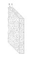
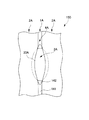
図1は、繊維ウェブの斜視図である。図2は、第1実施形態の吸収体における斜視断面図である。図3は、(A)第1実施形態の吸収体における平面図及び(B)第1実施形態の吸収体における底面図である。図4は、(A)網状支持部材の平面図及び(B)網状支持部材の斜視図である。図5は、図1の繊維ウェブが下面側を図4の網状支持部材に支持された状態で上面側に気体を噴きあてられて図2の第1実施形態の吸収体が製造された状態を示す図である。図6は、吸収体製造装置を説明する側面図である。図7は、吸収体製造装置を説明する平面図である。図8は、図6における領域Zの拡大斜視図である。図9は、図6における噴き出し部の底面図である。図10は、第2実施形態の吸収体における斜視断面図である。図11は、第2実施形態の吸収体における平面図である。図12は、図11における(A)A―A´断面図及び(B)B―B´断面図である。図13は、(A)第2実施形態の吸収体における平面図及び(B)第2実施形態の吸収体における底面図である。図14は、(A)網状支持部材に細長状部材を等間隔で並列配置した支持部材の平面図及び(B)網状支持部材に細長状部材を等間隔で並列配置した支持部材の斜視図である。図15は、図1の繊維ウェブが下面側を図14の支持部材に支持された状態で上面側に気体を噴きあてられて図10の第2実施形態の吸収体が製造された状態を示す図である。図16は、第3実施形態の多層吸収体における斜視断面図である。図17は、第4実施形態の多層吸収体における斜視断面図である。図18は、第4実施形態の多層吸収体における開口部近傍の構造を説明する図である。図19は、第5実施形態の多層吸収体における斜視断面図である。図20は、第6実施形態の吸収体における斜視断面図である。図21は、第7実施形態の吸収体における斜視断面図である。図22は、第8実施形態の吸収体における斜視断面図である。図23は、本発明の吸収性物品における斜視断面図である。図24は、(A)楕円状の開口部が複数開口された板状支持部材の平面図及び(B)楕円状の開口部が複数開口された板状支持部材の斜視図である。 FIG. 1 is a perspective view of a fibrous web. FIG. 2 is a perspective sectional view of the absorbent body according to the first embodiment. 3A is a plan view of the absorbent body according to the first embodiment, and FIG. 3B is a bottom view of the absorbent body according to the first embodiment. FIG. 4A is a plan view of the mesh support member, and FIG. 4B is a perspective view of the mesh support member. FIG. 5 shows a state in which the absorbent body of the first embodiment of FIG. 2 is manufactured by spraying gas on the upper surface side with the fiber web of FIG. 1 supported on the lower surface side by the mesh-like support member of FIG. FIG. FIG. 6 is a side view illustrating the absorbent body manufacturing apparatus. FIG. 7 is a plan view illustrating the absorbent body manufacturing apparatus. FIG. 8 is an enlarged perspective view of a region Z in FIG. FIG. 9 is a bottom view of the ejection portion in FIG. FIG. 10 is a perspective cross-sectional view of the absorber according to the second embodiment. FIG. 11 is a plan view of the absorber according to the second embodiment. 12A and 12B are a cross-sectional view taken along line AA ′ and a cross-sectional view taken along line B-B ′ in FIG. 13A is a plan view of the absorber of the second embodiment, and FIG. 13B is a bottom view of the absorber of the second embodiment. 14A is a plan view of a support member in which elongated members are arranged in parallel at equal intervals on the mesh support member, and FIG. 14B is a perspective view of the support member in which elongated members are arranged in parallel at equal intervals on the mesh support member. is there. FIG. 15 shows a state in which the absorbent body of the second embodiment of FIG. 10 is manufactured by spraying gas onto the upper surface side of the fiber web of FIG. 1 with the lower surface side supported by the support member of FIG. FIG. FIG. 16 is a perspective sectional view of the multilayer absorbent body according to the third embodiment. FIG. 17 is a perspective sectional view of the multilayer absorbent body according to the fourth embodiment. FIG. 18 is a diagram illustrating a structure in the vicinity of the opening in the multilayer absorber according to the fourth embodiment. FIG. 19 is a perspective sectional view of the multilayer absorbent body according to the fifth embodiment. FIG. 20 is a perspective cross-sectional view of the absorber according to the sixth embodiment. FIG. 21 is a perspective cross-sectional view of the absorbent body according to the seventh embodiment. FIG. 22 is a perspective sectional view of the absorber according to the eighth embodiment. FIG. 23 is a perspective sectional view of the absorbent article of the present invention. 24A is a plan view of a plate-like support member having a plurality of elliptical openings, and FIG. 24B is a perspective view of the plate-like support member having a plurality of elliptical openings.
[1]吸収体
図1から図22により、本発明の吸収体における実施形態について説明する。
[1] Absorber An embodiment of the absorber of the present invention will be described with reference to FIGS.
[1.1]第1実施形態
図1から9により、第1実施形態における吸収体について説明する。
[1.1] First Embodiment An absorbent body according to the first embodiment will be described with reference to FIGS.
[1.1.1]吸収体
図2、図3(A)及び図3(B)に示すように、本実施形態における吸収体110は、吸水性繊維を含む吸収体であり、該吸収体110の一面側に複数の溝部1が略等間隔で並列的に形成された吸収体である。そして、略等間隔で形成された複数の溝部1それぞれの間に、複数の凸状部2それぞれが形成されている。この凸状部2は、溝部1と同様に略等間隔で並列的に形成されている。ここで、本実施形態において、溝部1は略等間隔で並列的に形成されているがこれに限定されず、例えば、異なる間隔ごとに形成されても良く、また、並列的でなく溝部1同士の間隔が変化するように形成されていてもよい。
[1.1.1] Absorber As shown in FIG. 2, FIG. 3 (A) and FIG. 3 (B), the
また、本実施形態における吸収体110の凸状部2の高さ(厚さ方向)は略均一であるが、例えば、互いに隣接する凸状部2の高さが異なるように形成されていてもよい。例えば、後述する製造装置90における、主に気体からなる流体が噴き出される噴き出し口913の間隔を調整することで、凸状部2の高さを調整することができる。例えば、噴き出し口913の間隔を狭くすることで凸状部2の高さを低くすることができ、逆に、噴き出し口913の間隔を広くすることで凸状部2の高さを高くすることができる。更には、噴き出し口913の間隔を狭い間隔と広い間隔とが交互になるよう形成することで、高さの異なる凸状部2が交互に形成されるようにすることもできる。また、このように、凸状部2の高さが部分的に変化していれば、肌との接触面積が下がるために肌への負担を減らすことができるというメリットも生じる。
Moreover, although the height (thickness direction) of the
本実施形態において、凸状部2は高目付領域であり、溝部1は低目付領域である。つまり、本実施形態における吸収体110は、所定方向に連続的に形成され該吸収体における平均目付よりも低い目付である低目付領域と、低目付領域の両側に該低目付領域に沿うように形成される平均目付よりも高い目付である高目付領域と、をそれぞれ複数備える。複数の高目付領域それぞれは、高目付領域を構成する繊維における所定(縦)方向に対して−45℃から+45℃に配向される繊維である縦配向繊維の含有率が、縦配向繊維ではない横配向繊維の含有率よりも高い。そして、複数の低目付領域それぞれは、低目付領域を構成する繊維における横配向繊維の含有率が、縦配向繊維の含有率よりも高い。
In the present embodiment, the
繊維配向の測定は、株式会社キーエンス製のデジタルマイクロスコープVHX−100を用いて行い、以下の測定方法で行った。(1)サンプルを観察台上に長手方向が縦方向になるようにセットし、(2)イレギュラーに手前に飛び出した繊維を除いてサンプルの最も手前の繊維にレンズのピントを合わせ、(3)撮影深度(奥行き)を設定してサンプルの3D画像をPC画面上に作成する。次に(4)3D画像を2D画像に変換し、(5)測定範囲において長手方向を適時等分する平行線を画面上に複数引く。(6)平行線を引いて細分化した各セルにおいて、繊維配向が長手方向であるか、幅方向であるかを観察し、それぞれの方向に向いている繊維本数を測定する。そして(7)設定範囲内における全繊維本数に対し、長手方向に向かう繊維配向の繊維本数の割合と、幅方向に向かう繊維配向の繊維本数の割合とを計算することにより、算出・測定することができる。 The fiber orientation was measured using a digital microscope VHX-100 manufactured by Keyence Corporation, and the following measurement method was used. (1) Set the sample on the observation table so that the longitudinal direction is the vertical direction. (2) Focus the lens on the foremost fiber of the sample except for the irregularly protruding fiber. (3 ) Set the shooting depth (depth) and create a sample 3D image on the PC screen. Next, (4) the 3D image is converted into a 2D image, and (5) a plurality of parallel lines that equally divide the longitudinal direction in the measurement range are drawn on the screen. (6) In each cell subdivided by drawing parallel lines, it is observed whether the fiber orientation is the longitudinal direction or the width direction, and the number of fibers oriented in each direction is measured. (7) Calculate / measure by calculating the ratio of the number of fibers oriented in the longitudinal direction and the ratio of the number of fibers oriented in the width direction relative to the total number of fibers in the set range. Can do.
ここで、本実施形態における吸収体110を生理用ナプキン等の吸収性物品に用いた場合、例えば、高目付領域である凸状部2を構成する繊維101は、凸状部2が連続して形成される方向(例えば、ライン流れ方向)に配向しているため、表面シートから移行された経血等の液体は、繊維配向である凸状部2が連続する方向に沿って滲むこととなる。また、高目付領域である凸状部2と隣り合う低目付領域である溝部1は、単位面積当たりの構成繊維本数が少ないことから毛細管力が低下しているため、経血等の液体は、より凸状部2が連続する方向と交差する方向である幅方向へ滲みにくくなる。
Here, when the
また、吸収体110には低目付領域である溝部1が形成されているため、屈曲しやすくなる。このため、吸収性物品は身体の形状に対応して変形しやすく、より身体にフィットしやすくなる。更に、溝部1は低目付であっても、該溝部1を構成する繊維が該溝部1における幅方向に配向しているため、該吸収体110における幅方向(溝部1における幅方向)への強度が高い。これにより、例えば、吸収性物品を身体に装着した状態における動作変化により、ヨレたり破損してしまうことが抑制できる。
Moreover, since the groove |
また、吸収体110の肌面に設けられる表面シートとは、主に高目付領域である凸状部2と接触する。言い換えると、表面シートは、低目付領域である溝部1と実質的に接触しないため、外圧等による経血の逆戻り(リウェット)を抑制できる。
Moreover, the surface sheet provided in the skin surface of the
[1.1.2]製造方法
図1、図6から図9により、吸収体110の製造方法を説明する。まず、図1に示す吸水性繊維を含む繊維ウェブ100を通気性支持部材である図4に示す網状支持部材210の上面側に載置する。言い換えると、繊維ウェブ100を網状支持部材210により下側から支持する。繊維ウェブ110を網状支持部材210に載置する方法として、シート状に形成された繊維ウェブ100を網状支持部材210の上面側に載置するほか、例えば、吸水性繊維を含む繊維を、網状支持部材210における上面に、エアレイド法により積層させる方法も例示できる。
[1.1.2] Manufacturing Method A manufacturing method of the
そして、この繊維ウェブ100を支持した状態における網状支持部材210を所定方向に移動させ、該移動されている繊維ウェブ100の上面側から連続的に気体を噴きあてることで、本実施形態における吸収体110を製造することができる。
Then, the
網状支持部材210は、図4に示すように、不通気部である所定太さの複数のワイヤ211が、織り込まれるようにして形成される。複数のワイヤ211が所定間隔を開けて織り込まれることで、通気部である孔部233が複数形成された網状支持部材210が得られる。
As shown in FIG. 4, the net-
網状支持部材210は、上述の通り、孔径が小さな孔部233が複数形成されているものであり、繊維ウェブ100の上面側から噴きあてられた気体は、該網状支持部材210に妨げられることなく下方に通気する。この網状支持部材210は、噴きあてられる気体の流れを大きく変えることがなく、また、繊維101を該網状支持部材の下方向に移動させない。
As described above, the mesh-
このため、繊維ウェブ100における繊維101は、主に上面側から噴きあてられた気体により所定方向に移動される。具体的には、網状支持部材210の下方側への移動が規制されているため、繊維101は、該網状支持部材210の表面に沿うような方向に移動する。
For this reason, the
例えば、気体が噴きあてられた領域における繊維101は、該領域に隣接する領域に移動される。そして、気体が噴きあてられる領域が所定方向に移動するため、結果として、気体が噴きあてられた所定方向に連続する領域における側方の領域に移動される。
For example, the
これにより、溝部1が形成されると共に、溝部1と隣接する溝部1との間に凸状部2が形成される。溝部1における底部の繊維101は幅(横)方向に配向し、該凸状部2における側方部の繊維密度が高くなると共に長手(縦)方向に配向等される。
Thereby, the
ここで、繊維ウェブ100は、吸水性繊維のみで構成しても良く、また、吸水性繊維と熱融着性繊維とを混合して構成してもよい。具体的には、パルプを80から100質量%、ポリエチレンとポリプロピレンの芯鞘構造からなる繊維を20から0質量%で混合し、目付を10から1000g/m2に調整したものを用いることができる。繊維ウェブ100を構成する繊維の平均繊維長は、1から20mm、好ましくは2から10mmである。
Here, the
この吸水性繊維とは、吸水性を有する繊維及び吸水性が付与された繊維をいう。吸収性を有する繊維として、例えば、セルロース系繊維を例示できる。また、吸水性が付与された繊維として、例えば、親水処理した合成繊維や収縮繊維を例示できる。詳細には後述の通りである。 This water-absorbing fiber refers to a fiber having water absorption and a fiber to which water absorption is imparted. As a fiber which has absorptivity, a cellulose fiber can be illustrated, for example. Moreover, as a fiber to which water absorption was given, the synthetic fiber and shrinkable fiber which carried out the hydrophilic process can be illustrated, for example. Details will be described later.
また、繊維長が短い繊維からなる繊維ウェブ100の所定面に、主に気体からなる流体を噴きあてることで、複数の溝部1及び複数の凸状部2を形成するため、この場合において、網状支持部材210における繊維ウェブ100とは反対側から吸引(吸気)することが好ましい。例えば、繊維ウェブ100における所定面に主に気体からなる流体が噴きあてられる直前に、吸引(吸気)を開始することができる。
Moreover, in order to form the some
このように、網状支持部材210における反対側から吸引(吸気)することで、繊維ウェブ100を網状支持部材210に密着させ、主に気体からなる流体が噴きあてられることによる繊維の飛散を抑制できる。これにより、繊維ウェブ100における所定面において複数の溝部1及び複数の凸状部2の形状が好適に形成される。
Thus, by sucking (inhaling) from the opposite side of the mesh-
[1.1.3]吸収体製造装置
図6から図9により、吸収体110を製造する吸収体製造装置90について説明する。
[1.1.3] Absorber Manufacturing Device An
吸収体製造装置90は、繊維集合体である繊維ウェブ100を一方の面側から支持する通気性支持部材と、通気性支持部材により前記一方の面側から支持される繊維ウェブ100に、繊維ウェブ100における他方の面側から主に気体からなる流体を噴きあてる噴きあて手段である噴き出し部910及び不図示の送気部と、繊維ウェブ100を所定方向Fに移動させる移動手段であるコンベア930と、を備える。
The absorbent
そして、前記移動手段であるコンベア930は、通気性支持部材により一方の面側から支持された状態における繊維ウェブ100を所定方向Fに移動させ、噴きあて手段である噴き出し部910及び不図示の送気部は、移動手段であるコンベア930により所定方向Fに移動される通気性支持部材により一方の面側から支持される繊維ウェブ100における他の面側に、主に気体からなる流体を噴きあてる。
The
これにより、繊維ウェブ100を構成する繊維101は、噴き出し部910から噴き出される(噴きあてられる)主に気体からなる流体、及び/又は、この噴き出し部910から噴き出される(噴きあてられる)主に気体からなる流体であって、繊維ウェブ100を通気すると共に後述する通気性支持部材に形成される不通気部によって流れの方向が変えられた主に気体からなる流体により、繊維ウェブ100を構成する繊維101移動させる。この繊維101の移動を調整することで、繊維ウェブ100における繊維配向、繊維疎密又は繊維目付を調整し、所定の溝部1(及び凸状部2)や後述する開口部3を形成することができる。
As a result, the
ここで、主に気体からなる流体の噴きあて条件を変更することで、繊維ウェブ100を構成する繊維101の移動を調整することができる。つまり、通気性支持部材における通気部及び吸収体通気部の形状及び配置に加えて、主に気体からなる流体の噴きあて条件を調整することで、吸収体3の繊維配向、繊維疎密又は繊維目付、所定の溝部1(及び凸状部2)や後述する開口部3形状等を調整することができる。
Here, the movement of the
[1.2]第2実施形態
図11から図15により、第2実施形態における吸収体について説明する。第2実施形態における吸収体120は、第1実施形態における吸収体110の低目付領域である溝部1に、所定間隔で複数の開口部3が形成された吸収体である。ここで、本実施形態において、溝部1は略等間隔で並列的に形成されているがこれに限定されず、例えば、異なる間隔ごとに形成されても良く、また、並列的でなく溝部1同士の間隔が変化するように形成されていてもよい。また、凸状部2における高さも、均一でなく互いに異なる高さになるように形成することができる。また、本実施形態において、複数の開口部3が形成されているが、複数の窪み部(不図示)が形成されていてもよい。
[1.2] Second Embodiment An absorbent body according to the second embodiment will be described with reference to FIGS. 11 to 15. The
[1.2.1]吸収体
図14に示すように、本実施形態の吸収体120における溝部1は、開口部3が形成されている領域においては幅広で、開口部3が形成されていない領域では幅狭になるよう形成される。逆に、凸状部2は、開口部3が形成されている領域においては幅狭で、開口部3が形成されていない領域では幅広になるように形成される。
[1.2.1] Absorber As shown in FIG. 14, the
また、凸状部2の高さ(厚さ方向における長さ)は、凸状部2が延びる方向において均一でない場合がある。つまり、図11、図12(A)及び図12(B)に示すように、溝部1において開口部3が形成される領域に隣接する凸状部2の高さHaは、開口部3が形成されていない領域に隣接する凸状部2の高さHbよりも低い。詳細には、高目付領域である凸状部2における窪み部(不図示)又は開口部3の両側に配置される側方領域の厚さ方向への長さは、高目付領域における側方領域ではない領域の厚さ方向への長さよりも短い。
Further, the height (length in the thickness direction) of the
凸状部2が連続して延びる方向において、凸状部2における頂部は、緩やかな波状の起伏を形成する。また、凸状部2は、凸状部2が延びる方向において、厚さ方向への高さが低い第1凸状部2Lと、厚さ方向への高さが高い第2凸状部2Hとが交互に連続して形成されるといえる。
In the direction in which the
開口部3の周囲の繊維101は、該開口部3の周囲(周縁)に沿うように配向している。言い換えると、開口部3における溝部1の長手方向端部は、該長手方向に対して交差する方向に配向している。また、開口部3における溝部1の長手方向側部は、該長手方向に沿う方向に配向している。
The
開口部3とこれに隣接する開口部3との間には、凸状部2とこれに隣接する凸状部2とを繋ぐように形成される連結部4が形成される。言い換えると、所定間隔で形成される複数の連結部4が、凸状部2とこれに隣接する凸状部2とを連結しているともいえる。
A connecting
凸状部2は、上述の通り、溝部1に比べて繊維101の目付が高くなるよう調整されている。また、溝部1の目付は、溝部1と凸状部2とを含む全体における目付の平均に比べて低くなるよう調整される。
As described above, the
ここで、本実施形態における吸収体120を生理用ナプキン等の吸収性物品に用いた場合、吸収体120には、低目付領域である溝部1に開口部3が形成されているので、例えば、高粘度経血が排泄されたとしても開口部3に落とし込むことが可能であり、高粘度経血等が吸収体における表面全面を覆うことを抑制できる。これにより、例えば、吸収性物品における吸収性の悪化を抑制することができる。
Here, when the
また、凸状部2における厚さ方向への高さが、該凸状部2が連続して形成される方向(ライン流れ方向、長手方向)において高い部分と低い部分とを有するので、例えば、凸状部2が連続して形成される方向(ライン流れ方向、長手方向)においても屈曲しやすくなる。これにより、例えば、吸収性物品を身体に装着した状態において、より一層身体の形状に沿って変形し、身体にフィットする。
Moreover, since the height in the thickness direction of the
[1.2.2]製造方法
以下に、本実施形態における吸収体120を製造する方法について説明する。まず、吸水性繊維を含む繊維ウェブ100を、通気性支持部材である図14に示す支持部材220の上面側に載置する。言い換えると、繊維ウェブ100を支持部材220により下側から支持する。
[1.2.2] Manufacturing Method A method for manufacturing the
そして、この繊維ウェブ100を支持した状態における支持部材220を所定方向に移動させ、該移動されている繊維ウェブ100の上面側から連続的に気体を噴きあてることで、本実施形態における吸収体120を製造することができる。
And the
繊維ウェブ100を上面側に載置した支持部材220は、細長状部材225の長手方向に略直交する方向に移動する。これにより、繊維ウェブ100の上面側に、細長状部材225に略直交する方向に気体が連続的に噴きあてられることになる。つまり、溝部1は、細長状部材225と略直交する方向に形成される。そして、後述する開口部3は、細長状部材225と溝部1とが交差する位置に形成される。
The
上述の通り、支持部材220は、網状支持部材210の上面に、複数の細長状部材225を所定間隔で略平行に配置した支持部材である。細長状部材225は、不通気性の部材であり、例えば、上方側から噴きあてられた気体を下方側に通気させない。言い換えると、細長状部材225に噴きあてられた気体は、その流れ方向が変更される。
As described above, the
また、細長状部材225は、繊維ウェブ100における繊維101を、支持部材220の下方側に移動させない。
Further, the
このため、繊維ウェブ100を構成する繊維101の移動は、繊維ウェブ100の上面側から噴きあてられる気体及び/又は、噴きあてられた気体であって繊維ウェブ100を通気すると共に細長状部材225によって流れの方向が変えられた気体により移動される。
For this reason, the movement of the
例えば、気体が噴きあてられた領域における繊維101は、該領域に隣接する領域に移動される。そして、気体が噴きあてられる領域が所定方向に移動するため、結果として、気体が噴きあてられた所定方向に連続する領域における側方の領域に移動される。
For example, the
これにより、溝部1が形成されると共に、溝部1における底部の繊維101は幅(横)方向に配向するよう移動される。また、溝部1と溝部1との間に凸状部2が形成され、該凸状部2における側方部の繊維密度が高くなり、繊維101が長手方向に配向等される。
Thereby, the
更に、噴きあてられた気体であって繊維ウェブ100を通気すると共に細長状部材225によって流れの方向が変えられた気体は、繊維ウェブ100を構成する繊維101を上記とは異なる方向に移動させる。
Further, the gas that has been blown and has passed through the
支持部材220を構成する網状支持部材210及び細長状部材225は、支持部材220の下面側への繊維101の移動を規制するので、繊維101は、支持部材220の上面に沿うような方向に移動される。
Since the net-
詳細には、細長状部材225に噴きあてられた気体は、該細長状部材225に沿うような方向に流れを変える。このように流れを変えた気体は、細長状部材225の上面に配置されている繊維101を、細長状部材225の上面から周囲の領域に移動させる。これにより、所定形状の開口部3が形成される。また、繊維101の配向、疎密又は目付の1又は2以上が調整される。
Specifically, the gas blown to the
更には、繊維ウェブ100に噴きあてる主に気体からなる流体の温度、量又は強さを調整し、また、移動手段における繊維ウェブ100の移動速度を調整しテンション等を調整することで、図24に示される板状支持部材230を用いても、本実施形態における吸収体120を得ることができる。
Further, the temperature, amount or strength of a fluid mainly composed of gas sprayed on the
ここで、第2実施形態における吸収体120は、上述した製造装置90により、製造することができる。この場合における製造装置90の動作は、上述の通りである。
Here, the
[1.3]第3実施形態
図16により、第3実施形態における多層吸収体140について説明する。第3実施形態における多層吸収体140は、第1繊維層141と、第1繊維層141における一方の面側に積層配置される吸収体142とを備える多層吸収体である。第1繊維層141における他方の面には、多層吸収体140における厚さ方向に窪む複数の溝部1Aと、厚さ方向に突出し複数の溝部1Aそれぞれに隣接すると共に溝部1Aにおける目付よりも高い目付である複数の凸状部2Aとが形成される。これら複数の溝部1A及び複数の凸状部2Aには、第1繊維層141及び吸収体142がそれぞれ積層配置される。そして、凸状部2Aにおける吸収体142は、該吸収体142における第1繊維層141側の面が第1繊維層141における他方の面と同じ側に突出する形状である。また、溝部1Aにおける吸収体142は、吸収体142における第1繊維層141側の面が第1繊維層141における他方の面と同じ側に窪んだ形状である。
[1.3] Third Embodiment
ここで、多層吸収体140において、溝部1Aは略等間隔で並列的に形成されているがこれに限定されず、例えば、異なる間隔ごとに形成されていても良く、また、並列的でなく溝部1A同士の間隔が変化するように形成されていてもよい。また、凸状部2Aにおける高さも、均一でなく互いに異なる高さになるように形成することができる。
Here, in the multilayer
そして、複数の凸状部2Aそれぞれは、該凸状部2Aを構成する繊維における縦配向繊維の含有率が、横配向繊維の含有率よりも高い。また、複数の溝部1Aそれぞれは、該複数の溝部1Aを構成する繊維における横配向繊維の含有率が、縦配向繊維の含有率よりも高い。
In each of the plurality of
[1.3.1]形状
図16に示すように、本実施形態における多層吸収体140は、上述の通り、第1繊維層141と吸収体142とが積層配置される。多層吸収体140は、多層吸収体140の一方の面側、具体的には第1繊維層141側に複数の溝部1Aが略等間隔で並列的に形成された吸収体である。そして、略等間隔で形成された複数の溝部1Aそれぞれの間に、複数の凸状部2Aそれぞれが形成されている。この凸状部2Aは、溝部1Aと同様に略等間隔で並列的に形成されている。ここで、本実施形態において、溝部1Aは略等間隔で並列的に形成されているがこれに限定されず、例えば、異なる間隔ごとに形成されても良く、また、並列的でなく溝部1A同士の間隔が変化するように形成されていてもよいことは上述の通りである。
[1.3.1] Shape As shown in FIG. 16, in the multilayer
これら複数の溝部1A及び複数の凸状部2Aは、第1繊維層141及び吸収体142がそれぞれ積層配置される。ここで、多層吸収体140における吸収体142は、単に厚さが均一なシート状ではなく、第1繊維層141側に形成される複数の溝部1A等の形状に応じた所定の形状である。
In the plurality of
凸状部2Aにおいて、第1繊維層141における吸収体142が配置される側とは反対側の面は、凸状部2Aの表面を構成する。この面は、多層吸収体140における厚さ方向の外側にU字状に突出する。そして、第1繊維層141における吸収体142側の面は、上記凸状部2Aの表面を構成する面と同じ側にU字状に突出する形状である。
In the
吸収体142における第1繊維層141側とは反対側の面であって多層吸収体140における他の表面を構成する面は、平面状に形成される。吸収体142における第1繊維層141側の面は、第1繊維層141における吸収体142側の面に沿うように凸状に変形している。つまり、吸収体142における第1繊維層141側の面は、第1繊維層141における表面側の面がU字状に突出する側と同じ側に突出する。
A surface of the
また、該溝部1Aにおける第1繊維層141の厚さは、凸状部2Aにおける吸収体142の厚さよりも薄い。更に、溝部1Aにおける第1繊維層141の厚さは、凸状部2Aにおける吸収体142の厚さよりも薄い。
In addition, the thickness of the
溝部1Aにおける第1繊維層141の表面側の面は、厚さ方向に薄くなるように窪んだ形状である。また、吸収体142における第1繊維層141側の面は、第1繊維層141における表面側の面と同じ側に窪んだ形状である。
The surface on the surface side of the
また、多層吸収体140の凸状部2Aにおける高さ(厚さ方向)は略均一であるが、例えば、互いに隣接する凸状部2Aの高さが異なるように形成されていてもよい。例えば、主に気体からなる流体が噴き出される噴き出し口913の間隔を調整することで、凸状部2Aの高さを調整することができる。例えば、吸収体製造装置90における噴き出し口913の間隔を狭くすることで凸状部2Aの高さを低くすることができ、逆に、噴き出し口913の間隔を広くすることで凸状部2Aの高さを高くすることができる。更には、噴き出し口913の間隔を狭い間隔と広い間隔とが交互になるよう形成することで、高さの異なる凸状部2Aが交互に形成されるようにすることもできる。また、このように、凸状部2Aの高さが部分的に変化していれば、肌との接触面積が下がるために肌への負担を減らすことができるというメリットも生じる。
Moreover, although the height (thickness direction) in the
ここで、凸状部2Aの高さは、0.3から15mm、特に0.5から5mmであることが好ましい。また、凸状部2Aの幅は、0.5から30mm、特に1.0から10mmであることが好ましい。互いに隣接する凸状部2Aの頂点同士間のピッチは0.5から30mm、特に3から10mmであることが好ましい。
Here, the height of the
凸状部2Aにおける吸収体142の高さ(厚さ方向における長さ)は、凸状部2Aにおける高さの95%以下、特には20から90%、更には40から70%が好ましい。ここで、吸収体142において、凸状部2Aにおける部分における高さ(厚さ方向における長さ)が、溝部1Aにおける部分における高さよりも高くなるように形成される。
The height (length in the thickness direction) of the
また、溝部1Aの高さは、凸状部2Aの高さにおける90%以下、特には1から50%、更には5から20%が好ましい。溝部1Aの幅は、0.1から30mm、特に0.5から10mmであることが好ましい。互いに隣接する溝部1A同士の距離は0.5から20mm、特には3から10mmであることが好ましい。溝部1Aにおける吸収体(内部層)142の高さは、溝部1Aにおける高さ(厚さ方向における長さ)の95%以下、特には20から90%、更には40から70%が好ましい。
Further, the height of the
ここで、凸状部2Aや溝部1Aにおける高さ、ピッチ、幅等の測定方向を以下に例示する。例えば、多層吸収体140をテーブル上に無加圧の状態で設置し、マイクロスコープにて多層吸収体140の断面写真又は断面映像から測定する。測定対象の多層吸収体140は、凸状部2Aの頂点及び溝部1Aを通るように切断する。
Here, the measurement directions such as the height, pitch, and width in the
そして、高さ(厚さ方向における長さ)を測定する際は、多層吸収体140の最下位置(つまりテーブル表面)から上方に向かう凸状部2A及び溝部1Aそれぞれの最高位置を高さとして測定する。
When measuring the height (length in the thickness direction), the highest positions of the
ピッチを測定する際は、隣接する凸状部2Aの最高位置となる頂点間を測定し、隣接する溝部1Aの中心位置となる中心間を測定する。
When measuring the pitch, the distance between the vertices that are the highest positions of the adjacent
幅を測定する際は、多層吸収体140の最下位置(つまりテーブル表面)から上方に向かう凸状部2A底面の最大幅を測定し、溝部1Aも同様に溝部1Aにおける底面の最大幅を測定する。
When measuring the width, the maximum width of the bottom surface of the
ここで、凸状部2Aの断面形状は、例えば、ドーム状、台形状、三角状、Ω状、四角状等を例示することができ、その形状は特に限定されない。例えば、吸収性物品等の表面シートとして用いた場合、着用者への肌触りを考慮すると凸状部2Aにおける頂面及び側面は曲線(曲面)であることが好ましい。また、着圧等で凸状部2Aが潰されたり、溝部1による空間が潰されたりすることを抑制するためには、溝部1Aにおける底面から頂面に向けて幅が狭くなるような形状であることが好ましく、例えば、断面形状がドーム状である場合を好ましい形状として例示できる。
Here, examples of the cross-sectional shape of the
また、凸状部2Aにおける吸収体(内部層)142の断面形状は、上述の形状についての説明の通り所定形状に形成することができ、特に限定されないが、例えば、吸収体142の剛直感が着用者へ伝わりにくくするにはドーム状等の曲線(曲面)状であることが好ましい。
Further, the cross-sectional shape of the absorber (inner layer) 142 in the
更に、例えば、吸収体142を硬い繊維層(潰れにくい繊維)で構成することで、凸状部2Aを厚さ方向に潰れにくくすることができる。
Furthermore, for example, by forming the
例えば、第1繊維層141を構成する繊維102は、多層吸収体140を構成する繊維101、102における平均自由度よりも自由度が高い状態にし、吸収体142を構成する繊維101における平均自由度よりも自由度が低い状態にすることができる。例えば、吸収体142を構成する繊維101における自由度は、第1繊維層141を構成する繊維101における自由度よりも低くなるように調整できる。ここで、繊維の平均自由度とは、例えば、第1繊維層141を構成する繊維102及び吸収体142を構成する繊維101における自由度の平均である。
For example, the
第1繊維層141を構成する繊維102の自由度を高い状態にするために、例えば繊維101同士の交点強度が部分的に異なるように構成することができる。具体的には、第1繊維層141は、該第1繊維層141を構成する繊維同士の交点における全部又は一部が、接合強度が弱くなるように、又は接合しないように調整することができる。
In order to make the freedom degree of the
第1繊維層141は、該第1繊維層141を構成する繊維同士の交点における全部又は一部が、接合強度が弱くなるように、又は接合しないように調整するためには、例えば、繊維102の表面における樹脂成分の融点が異なる複数の繊維を配合する場合を例示できる。例えば、低密度ポリエチレン(融点110℃)とポリエチレンテレフタレートの芯鞘構造である繊維Aと、高密度ポリエチレン(融点135℃)とポリエチレンテレフタレートの芯鞘構造である繊維Bとを、繊維A:繊維B=70:30の混合比で繊維ウェブ100を構成し、この繊維ウェブ100をオーブン等により120℃で加熱処理する。これにより、繊維ウェブ100における繊維A同士の交点、及び繊維Aと繊維Bとの交点では低密度ポリエチレンが溶融するため繊維同士は熱融着する。ここで、繊維A同士の交点強度の方が溶融する低密度ポリエチレンの量が多いため交点強度は高くなる。また、繊維B同士の交点においては、高密度ポリエチレンが溶融しないため熱融着しない。つまり、繊維A同士の交点強度>繊維Aと繊維Bとの交点強度>繊維B同士の交点強度という関係で熱融着等された状態となる。この場合において、例えば、吸収体142を融点が120℃以下の繊維で構成することで、吸収体142における繊維同士の交点強度を、第1繊維層141における繊維交点強度よりも高くすることができる。
In order to adjust the
第1繊維層141を構成する繊維102として、多層吸収体140における平均繊維長よりも長い繊維を用いることができる。また、第1繊維層141を構成する繊維102として、該繊維102の長さが吸収体142を構成する繊維101の長さよりも長い繊維を用いることができる。繊維長が長いほど繊維間距離を広くすることができ、繊維同士がぶつかりにくくなるため繊維同士の自由度が高い。
As the
吸収体142を構成する繊維101として、多層吸収体140における平均繊維長さよりも短い繊維を用いることができる。また、吸収体142を構成する繊維101として、該繊維101の長さが第1繊維層141を構成する繊維102の長さよりも短い繊維を用いることができる。繊維長が短いほど繊維間距離を狭くすることができ、繊維密度を高めることができる。これにより、凸状部2Aにおいて密度勾配を設けることができるため、凸状部2Aの頂部に少量の経血や汗が付着しても、吸収体142へ経血等の液体を好適に移行させることができる。例えば、繊維長が短いパルプを多く含む繊維を用いることができる。
As the
吸収体142を構成する繊維101の自由度を低くするために、例えば、吸収体142に3次元捲縮形状の繊維を含有させることができる。3次元捲縮形状とは、例えば、スパイラル状、ジグザグ状、Ω状等を例示できる。例えば、全体的な繊維配向が平面方向を向き、部分的には厚み方向へ向くように配合された場合、繊維自体の挫屈強度が厚み方向へ働くため、外圧が加わっても吸収体が潰れにくくなる。
In order to reduce the degree of freedom of the
更に、3次元捲縮形状がスパイラル状であれば、例えば、外圧が解放されたときに形状が元に戻ろうとするため、過剰な外圧で吸収体142が若干潰れても外圧解放後には元の厚みに戻りやすくなるため好ましい。
Furthermore, if the three-dimensional crimped shape is a spiral shape, for example, when the external pressure is released, the shape tends to return to the original shape. Therefore, even if the
3次元捲縮形状の設け方は、機械捲縮による形状付与と熱収縮による形状付与がある。機械捲縮とは、紡糸後の連続で直線状の繊維に対し、ライン速度の周速差・熱・加圧によって制御でき、単位長さ当たりの捲縮個数が多いほど、外圧下に対する挫屈強度を高めることができる。具体的には、捲縮個数は10から35個/inch、更には15から30個/inchの範囲から選ばれる。 There are two ways of providing a three-dimensional crimped shape: shape imparting by mechanical crimping and shape imparting by heat shrinkage. Mechanical crimping can be controlled by the difference in peripheral speed of the line speed, heat, and pressurization for continuous and linear fibers after spinning. The larger the number of crimps per unit length, the greater the buckling against external pressure. Strength can be increased. Specifically, the number of crimps is selected from the range of 10 to 35 / inch, and further 15 to 30 / inch.
熱収縮による形状付与とは、例えば、融点の異なる2つ以上の樹脂からなり、熱を加えると融点差により熱収縮率が異なることにより3次元捲縮させることである。繊維断面の樹脂構成は、芯鞘構造の偏芯タイプ、左右成分の融点が異なるサイドバイサイドタイプが挙げられる。このような繊維の熱収縮率は、5から90%、更に10から80%の範囲が好ましい。 The shape imparting by heat shrinkage is, for example, made of two or more resins having different melting points, and when heat is applied, the heat shrinkage varies depending on the melting point difference, thereby causing three-dimensional crimping. Examples of the resin configuration of the fiber cross section include an eccentric type with a core-sheath structure and a side-by-side type in which the melting points of the left and right components are different. The heat shrinkage rate of such fibers is preferably 5 to 90%, more preferably 10 to 80%.
ここで、熱収縮率の測定方法は、(1)測定する繊維100%で200g/m2の繊維ウェブを作成し、(2)250×250mmの大きさにカットし、(3)145℃のオーブン内に5分間放置し、(4)熱収縮後の長さ寸法を測定し、(5)熱収縮前後の長さ寸法差から熱収縮率を算出する。 Here, the method for measuring the heat shrinkage rate is as follows: (1) Create a fiber web of 200 g / m 2 with 100% of the fiber to be measured, (2) cut into a size of 250 × 250 mm, and (3) 145 ° C. It is left in the oven for 5 minutes, (4) the length dimension after heat shrinkage is measured, and (5) the heat shrinkage rate is calculated from the length dimension difference before and after heat shrinkage.
吸収体142における3次元捲縮形状の繊維の含有率は、例えば、30質量%以上、特には50質量%以上であることが好ましい。3次元捲縮形状の繊維の含有率が30質量%以上である場合には、吸収体142において圧縮維持性及び圧縮回復性を得やすいため好ましい。
The content of the three-dimensional crimped fiber in the
ここで、第1繊維層141においても同様に3次元捲縮形状の繊維を含有させることができる。第1繊維層141における3次元捲縮形状の繊維の含有率は、例えば、70質量%以下、特には50質量%以下が好ましい。第1繊維層141を構成する繊維101として3次元捲縮形状の繊維が含まれることで、第1繊維層141における繊維密度を低くすることができる。この場合、第1繊維層141から吸収体142への液体の移行性が良好となるため好ましい。また、第1繊維層141における3次元捲縮形状の繊維の含有率を70質量%以下とすることで、3次元捲縮形状の繊維端面(切り口)が肌にあたることによる異物感を抑制することができる。
Here, the
また、吸収体142を構成する繊維101として、第1繊維層141を構成する繊維101よりもヤング率が高い繊維を用いることができる。
Further, as the
ここで、吸収体142を構成する繊維101として用いられるヤング率の高い繊維として、繊維度が大きな繊維を用いることができる。例えば、第1繊維層141を構成する繊維102における繊維度よりも大きな繊維度である繊維を用いることができる。
Here, as the fiber having a high Young's modulus used as the
また、吸収体142を構成する繊維101として、例えば、無機物の平均含有量が少ない繊維101を用いることができる。例えば、第1繊維層141を構成する繊維よりも無機物の平均含有量が少ない繊維102を用いることができる。無機物として、例えば、酸化チタン等の無機フィラーを例示できる。
Moreover, as the
前記吸収体142は、第1繊維層141を構成する繊維よりも繊維長が短い繊維を用いてエアレイド法により形成することができる。繊維長の短い繊維101を所定厚さに積層させて吸収体142を形成する場合、エアレイド法により好適に行うことができる。
The
繊維長が短い繊維をエアレイド法で積層する場合、繊維における繊維配向が繊維層の厚み方向へ向きやすい。経血等の液体は、繊維配向に沿って移行しやいので、例えば、吸収体(内部層)142をエアレイド法で積層することで繊維配向が厚さ方向に向くように調整した場合、吸収体(内部層)142へ移行した経血等の液体が、多層吸収体140の表面における平面方向に拡散することを抑制することが可能である。また、吸収体(内部層)142の繊維配向が厚み方向へ向いているため、挫屈強度が向上し、外圧が加わった場合でも凸状部が潰れにくくなるため好ましい。
When fibers having a short fiber length are laminated by the airlaid method, the fiber orientation in the fibers tends to be oriented in the thickness direction of the fiber layer. Since liquid such as menstrual blood easily moves along the fiber orientation, for example, if the fiber orientation is adjusted to be in the thickness direction by laminating the absorber (inner layer) 142 by the airlaid method, absorption It is possible to prevent liquid such as menstrual blood that has migrated to the body (inner layer) 142 from diffusing in the planar direction on the surface of the multilayer
[1.3.2]繊維配向、繊維疎密又は繊維目付
[1.3.2.1]繊維配向
図16に示すように、溝部1Aの底部における繊維101、102は、略幅方向(横方向)に配向している。第1繊維層141及び吸収体142における繊維101、102が、全体的に幅方向(横方向)に配向している。ここで、第1繊維層141及び吸収体142を構成する繊維101、102の自由度や性質等を調整することや、噴きあてる気体の強さを調整することで、第1繊維層141における繊維102の配向と、吸収体142における繊維101の配向とをそれぞれ調整することができる。例えば、第1繊維層141における幅方向に配向する繊維102の割合と、吸収体142における幅方向に配向する繊維101の割合とが異なるように調整することも可能である。
[1.3.2] Fiber Orientation, Fiber Density or Fiber Weight [1.3.2.1] Fiber Orientation As shown in FIG. 16, the
また、凸状部2における側部の繊維101、102は、該凸状部2の長手方向に沿う方向に配向している。例えば、該凸状部2の中央部(両側部の間の領域)における繊維101、102の配向と比べて長手方向に配向している。
Further, the
また、溝部1Aには、単位面積当たりの横配向繊維の含有率が中央部9よりも高く、側部8には、単位面積当たりの縦配向繊維の含有率が中央部9よりも高い。そして、中央部9には、厚さ方向に配向する繊維101、102が溝部1Aや側部8よりも多く含まれる。これにより、中央部9に例えば荷重がかかることにより凸状部2Aの厚みが減少したとしても、荷重を開放した場合には、その厚さ方向に配向する繊維101、102の剛性により元の高さに戻りやすくなる。すなわち、圧縮回復性の高い不織布を形成することができる。
The
[1.3.2.2]繊維疎密
図16に示すように、溝部1Aは、凸状部2Aに比べて繊維101、102の密度が低くなるように調整されている。また、溝部1Aの繊維密度は、主に気体からなる流体(例えば、熱風)の量やテンション等の諸条件によって任意に調整できる。
[1.3.2.2] Fiber Density As shown in FIG. 16, the
凸状部2Aは、上述の通り、溝部1Aに比べて繊維101、102の密度が高くなるように調整されている。また、凸状部2Aの繊維密度は、主に気体からなる流体(例えば、熱風)の量やテンション等の諸条件によって任意に調整できる。
As described above, the
[1.3.2.3]繊維目付
図16に示すように、溝部1Aは、凸状部2Aに比べて繊維101、102の目付が少なくなるよう調整されている。また、溝部1Aの目付は、溝部1Aと凸状部2Aとを含む全体における目付の平均に比べて低くなるよう調整される。
[1.3.2.3] Fiber basis weight As shown in FIG. 16, the
凸状部2Aは、上述の通り、溝部1Aに比べて繊維101、102の目付が多くなるよう調整されている。また、溝部1Aの目付は、溝部1Aと凸状部2Aとを含む全体における目付の平均に比べて低くなるよう調整される。
As described above, the
多層吸収体140全体の目付は、10から200g/m2、特には20から100g/m2である場合が好ましい。例えば、多層吸収体140を吸収性物品における表面シート兼吸収体として用いられる場合、多層吸収体140全体の目付が10g/m2より少ない場合には、例えば、使用中に容易に破損してしまう危険性があり、200g/m2より多い場合には、更に下方に他の吸収体が配置されていると、下方への液体の移行が円滑に行われにくくなる場合がある。
The basis weight of the entire multilayer
ここで、溝部1Aにおける目付は、凸状部2Aにおける目付に対して90%以下、特には3から90%、更には30から70%であることが好ましい。溝部1Aの目付が凸状部2Aの目付に対して90%より大きい場合、溝部1Aに落とし込んだ経血等の液体が下方側(他方側)へ移行する際の抵抗が高くなり、溝部1Aから経血が溢れだす場合がある。一方、溝部1Aにおける目付が凸状部2Aの目付に対して3%より小さい場合、多層吸収体140における強度が弱くなり、所定の用途に適さない場合がある。例えば、多層吸収体140を吸収性物品における表面シートとして用いた場合、該吸収性物品を使用している状態において破損する場合がある。
Here, the basis weight in the
凸状部2Aにおける目付は、例えば、15から250g/m2、特には25から120g/m2が好ましい。また、凸状部2Aにおける密度は0.20g/cm3以下、特には0.005から0.20g/cm3、更には0.007から0.07g/cm3が好ましい。
The basis weight in the
凸状部2Aにおける目付が15g/m2より少ない場合や、密度が0.005g/cm3より低い場合には、経血等の液体の重さや外圧によって凸状部2Aが潰れやすくなる場合がある。更には、一度吸収した経血が加圧下において逆戻りしやすくなる場合がある。
When the basis weight of the
凸状部2Aの目付が250g/m2より多い場合や、密度が0.20g/cm3より高い場合には、凸状部2Aに排泄された経血が下方へ移行しにくくなり凸状部2Aに滞留する場合がある。
When the basis weight of the
溝部1Aにおける目付は、例えば、3から150g/m2、特には5から80g/m2が好ましい。また、溝部1Aにおける密度は、0.18g/cm3以下、特には0.002から0.18g/cm3、更には0.005から0.05g/cm3が好ましい。
The basis weight in the
溝部1Aにおける目付が3g/m2より少ない場合や、密度が0.002g/cm3より低い場合、表面シート兼吸収体として用いられる場合には、例えば、上述のように多層吸収体140が表面シートとして配置された吸収性物品において、その使用中に容易に破損してしまう場合がある。
When the basis weight in the
一方で、溝部1Aにおける目付が150g/m2より多い場合や、密度が0.18g/cm3より高い場合には、溝部1Aに落とし込んだ経血等の液体が溝部1Aに溜まる場合がある。この場合には、液体が溝部1Aから溢れ出す場合がある。
On the other hand, when the basis weight in the
ここで、第1繊維層141と吸収体142との目付比は、10:90から90:10の範囲、特には20:80から50:50の範囲が好ましい。多層吸収体140を吸収性物品の表面シートとして用いる場合、表面シート兼吸収体として用いられる場合には、第1繊維層141における目付が、多層吸収体140の目付に対して10%より少ないと、第1繊維層が破損して吸収体が飛び出す危険性がある。逆に、第1繊維層141における目付が、多層吸収体140の目付に対して90%より多いと、吸収容量が少なく少量の排泄物等でも漏れてしまう場合がある。
Here, the basis weight ratio between the
溝部1Aや凸状部2Aが上述の条件を満たす場合、例えば、多層吸収体140に多量の経血が排泄された場合や高粘度の経血が排泄された場合でも、表面拡散を抑制することが可能である。例えば、多層吸収体140に外圧が加えられ凸状部2Aが若干潰されたとしても、溝部1(谷間)1Aにおける空間は保持されやすいため、この状態において経血等が排泄された場合でも表面に広く拡散することを抑制できる場合がある。更には、一度吸収した経血等が外圧下において逆戻りしても、肌との接触面積が少ないため肌に広く再付着しにくい場合がある。
When the
凸状部2Aの繊維目付が高くなるよう調整されることで、繊維本数が増大するため融着点数が増え、ポーラス構造が維持される。
By adjusting the fiber basis weight of the
ここで、本実施形態における多層吸収体140を生理用ナプキン等の吸収性物品に用いた場合、表面シートである第1繊維層141と吸収体142とを同時に成形しているため、表面シートである第1繊維層141と吸収体142との間に実質的な隙間がない。このため、吸収性物品における表面層から吸収体へ経血等の移送を好適に行うことができる。これは、後述する第4実施形態、第5実施形態及び吸収性物品においても同様である。
[1.3.3]製造方法
以下に、本実施形態における多層吸収体140を製造する方法について説明する。まず、略シート状に形成された繊維集合体であって該繊維集合体を構成する繊維が自由度を有する状態である不図示の第1繊維集合体と、第1繊維集合体における一方の面側に積層配置される略シート状に形成された吸水性繊維を含む繊維集合体であって該繊維集合体を構成する繊維が自由度を有する状態である不図示の吸収体用繊維集合体とを有する多層繊維集合体である繊維ウェブ100を、通気性支持部材である網状支持部材210の上面側に載置する。言い換えると、繊維ウェブ100を網状支持部材210により下側から支持する。ここで、所定の繊維を網状支持部材210における所定面に、上述の多層繊維集合体を形成するよう積層配置してもよい。
Here, when the multilayer
[1.3.3] Manufacturing Method A method for manufacturing the multilayer
そして、この繊維ウェブ100を支持した状態における網状支持部材210を所定方向に移動させ、該移動されている繊維ウェブ100の上面側から連続的に気体を噴きあてることで、本実施形態における多層吸収体140を製造することができる。
Then, the multi-layer absorption in the present embodiment is performed by moving the net-
本実施形態における多層吸収体140は、上述の吸収体製造装置90により製造することができる。この吸収体製造装置90における吸収体の製造方法等は、上述の記載を参考にすることができる。
The multilayer
[1.4]第4実施形態
図17により、第4実施形態における多層吸収体150について説明する。多層吸収体150は、第3実施形態の多層吸収体140における低目付領域である溝部1Aの底面に、所定間隔で開口部3Aが複数形成される多層吸収体である。
[1.4] Fourth Embodiment
ここで、多層吸収体150において溝部1Aの底面に低目付部である複数の開口部3Aが形成されているが、例えば、溝部1Aにおける多層吸収体150の厚さが薄くなるように形成された窪み部であってもよい。また、開口部3Aは、厚さ方向に完全に開口が形成されていないものも含む。
Here, in the multilayer
多層吸収体150の溝部1Aにおける底面は、該溝部1Aが形成される方向に沿って高低差を有する形状である。溝部1Aが形成される方向に複数の溝部1A等の低目付部が所定間隔で連続的に形成されると共に、溝部1Aが形成される方向に沿って高低差が形成されていることで、溝部1Aに沿って経血等の液体の流れを抑制できるため好ましい。
The bottom surface of the
図17又は図18に示すように、複数の開口部3Aそれぞれは、該開口部3Aそれぞれにおける周縁を構成する側壁部33Aにおける全部又は一部が、第1繊維層141の一部に覆われる。
As shown in FIG. 17 or FIG. 18, each of the plurality of
例えば、開口部3Aの溝部1Aが延びる方向における両側の側壁部33Aは、第1繊維層141に覆われ、開口部3Aの溝部1Aが延びる方向における側壁部33Aは、第1繊維層141に覆われていない。そして、この側壁部33Aにおける第1繊維層141に覆われていない領域においては、下層に配置される吸収体142が露出する。
For example, the
また、図18に示すように、溝部1Aにおける開口部3Aが形成されない領域において、溝部1Aの底部が、第1繊維層141で構成される領域と、吸収体142で構成される領域が存在する。具体的には、溝部1Aにおける開口部3Aの該溝部1Aが延びる方向における周縁近傍に、第1繊維層141によって覆われていない領域を有する。該領域において、吸収体142が露出される。
In addition, as shown in FIG. 18, in the region where the
また、第1繊維層141には、複数の溝部が形成されると共に、該溝部に沿うように多層吸収体150における開口部3Aに相当する位置に複数の開口部が形成される。該開口部は、多層吸収体150における開口部3Aよりも、溝部1Aが延びる方向に縦長の楕円形状に形成される。
The
ここで、本実施形態における多層吸収体150を生理用ナプキン等の吸収性物品に用いた場合、上述の第2実施形態における吸収体120を用いた場合と同様に、吸収性の悪化抑制や身体へのフィット性の向上等を達成することができる。
Here, when the multilayer
更に、第1繊維層141を主に合成繊維からなる繊維で構成し、吸収体142を主に吸水性繊維を主体とした繊維で構成した場合において、窪み部(不図示)及び/又は開口部3Aに落とし込まれた経血等の液体は、該窪み部及び/又は開口部3Aの幅方向における側壁部33Aから吸収されにくい。つまり、第1繊維層141により、低目付領域である溝部1Aに形成される窪み部(不図示)及び/又は開口部3Aの周縁を構成する側壁部33Aの全部又は一部が覆われているため、窪み部及び/又は開口部3Aに落とし込まれた経血等の液体は、幅方向における側壁部33Aから吸収体142の吸水性繊維へ移行しにくい。そして、溝部1Aが連続して形成される方向(例えば、ライン流れ方向)における側壁部33Aから吸収体142の吸水性繊維へ移行する。これにより、より一層、経血等の液体における幅方向への滲みを抑制することができる。
Further, in the case where the
[1.5]第5実施形態
図19により、第5実施形態における多層吸収体160について説明する。多層吸収体160は、第3実施形態の多層吸収体140に、第2繊維層が更に配置される多層吸収体である。つまり、第3実施形態の多層吸収体140における吸収体142の第1繊維層141側とは反対側の面に、第2繊維層143が更に配置された多層吸収体である。
[1.5] Fifth Embodiment A multilayer
第1繊維層141は、好ましくはカード法により積層されることで形成される。吸収体142は、好ましくは第1繊維層141における一方側の面に該吸収体142を構成する繊維をエアレイド法により積層させることで形成される。
The
第2繊維層143は、好ましくはカード法により積層されることで形成される。第2繊維層143を更に配置することで、所定機能や強度等を付与することが可能である。例えば、第2繊維層143を配置することで、形状維持性やクッション性等を向上させることができる。
The
本実施形態の多層吸収体160における製造方法について説明する。まず、略シート状に形成された繊維ウェブであって該繊維集合体を構成する繊維が自由度を有する状態である第1繊維ウェブと、第1繊維ウェブにおける一方の面側に積層配置される略シート状に形成された吸水性繊維を含む繊維ウェブであって該繊維集合体を構成する繊維が自由度を有する状態である吸収体用繊維ウェブと、吸収体用繊維ウェブにおける第1繊維層とは反対側に配置される略シート状に形成された繊維ウェブであって該繊維ウェブを構成する繊維が自由度を有する状態である第2繊維ウェブと、を有する多層繊維ウェブを、図4に示す網状支持部材210の所定面に配置することで、網状支持部材210に多層繊維集合体における一方の面側から支持させる。
The manufacturing method in the
次いで、所定の移動手段により、網状支持部材210により支持される多層繊維集合体を所定方向に移動させる。そして、例えば、噴きあて手段により、前記所定方向に移動される多層繊維集合体における他の面側から主に気体からなる流体を噴きあてる。
Next, the multilayer fiber assembly supported by the
ここで、網状支持部材210の所定面に第2繊維ウェブを配置し、第2繊維ウェブの網状支持部材210側とは反対側の面に、吸収体用繊維ウェブを構成する吸水性繊維を含有する繊維を積層させることにより吸収体用繊維ウェブを形成し、この形成された吸収体用繊維ウェブにおける第2繊維ウェブ側とは反対側に第1繊維ウェブを積層配置して多層繊維ウェブを形成することができる。ここで、吸収体用繊維ウェブは、例えば、第2繊維集合体における所定面にエアレイド法により形成される。
Here, the second fiber web is arranged on a predetermined surface of the net-
[1.6]第6実施形態
図20により、第6実施形態における吸収体111について説明する。吸収体111は、第1実施形態の吸収体110において、高分子吸収体103を更に含む吸収体である。
[1.6] Sixth Embodiment With reference to FIG. 20, an
図20に示すように、本実施形態の吸収体111において、高分子吸収体103は、低目付領域である溝部1及び高目付領域である凸状部2が形成される面とは反対の面側に偏って配置される。高分子吸収体103は、吸収体111を構成する繊維101と共に混合された状態で含まれる。この高分子吸収体103の形状は、粉状、粒状、繊維状と特にその形状は限定されない。
As shown in FIG. 20, in the
本実施形態の吸収体111は、吸水性繊維を含む繊維101と高分子吸収体103を混合して形成した繊維ウェブ100に、該繊維ウェブ100の一方の面側に主に気体からなる流体を噴きあてることで得ることができる。繊維ウェブ100の一方の面側に主に気体からなる流体を噴きあてることで溝部1及び凸状部2を形成すると共に、高分子吸収体103を他方の面側に移動させることができる。
The
吸収体111を上述の方法により製造する場合、主に気体からなる流体により吸収体111の外部に噴出されないよう、高分子吸収体103は、例えば、繊維状であることが好ましい。
When manufacturing the
本実施形態における吸収体111の溝部1及び凸状部2が形成される面側に、液体(例えば、経血)が連続的又は断続的に滴下された場合、該液体は、まず、吸水性繊維に吸収される。そして、吸水性繊維で吸収されなかった液体等は、高分子吸収体103に吸収される。ここで、高分子吸収体103は、溝部1及び凸状部2が形成される面とは反対の面側に偏って配置されるので、液体を吸収して膨張した場合でも、溝部1及び凸状部2の形状を崩しにくい。
When a liquid (for example, menstrual blood) is continuously or intermittently dropped on the surface of the
[1.7]第7実施形態
図21により、第7実施形態における吸収体112について説明する。吸収体112は、第1実施形態の吸収体110における溝部1に高分子吸収体103が配置された吸収体である。
[1.7] Seventh Embodiment With reference to FIG. 21, an
図21に示すように、本実施形態の吸収体112において、高分子吸収体103は、低目付領域である溝部1に配置される。具体的には、溝部1の窪みに高分子吸収体を収容するようにして配置される。これにより、吸収体112の上面側において、凸状部2の頭頂域と、高分子吸収体103とが表出する。本実施形態の吸収体112は、第1実施形態の吸収体110における溝部1の窪みに高分子吸収体103を収容させることで得ることができる。
As shown in FIG. 21, in the
本実施形態における吸収体112の溝部1及び凸状部2が形成される面側に、液体(例えば、経血)が連続的又は断続的に滴下された場合、凸状部2に滴下された液体は吸水性繊維に吸収され、高分子吸収体103に滴下された液体は直接高分子吸収体103に吸収される。
In the present embodiment, when liquid (for example, menstrual blood) is continuously or intermittently dropped on the surface side where the
[1.8]第8実施形態
図22により、第8実施形態における吸収体113について説明する。吸収体113は、第7実施形態における吸収体112の上面側に、第1実施形態の吸収体110を溝部1等が吸収体112側に向くように積層配置した吸収体である。
[1.8] Eighth Embodiment With reference to FIG. 22, an
図22に示すように、本実施形態の吸収体113において、高分子吸収体103は、積層された吸収体112と吸収体110との間に生じる空間に収容されるよう配置される。具体的には、吸収体113は、吸収体112における溝部1及び凸状部2が形成された面と、吸収体110における溝部1及び凸状部2が形成された面とを、互いの凸状部2の頭頂部が当接するように向き合わせて積層配置することで得ることができる。そして、吸収体113における吸収体112の溝部1と吸収体110の溝部1とが向き合う領域に、高分子吸収体103が配置される。
As shown in FIG. 22, in the
本実施形態における吸収体113の一方の面側に、液体(例えば、経血)が連続的又は断続的に滴下された場合、液体は、まず、吸水性繊維に吸収され、吸収性繊維で吸収されなかった液体等が高分子吸収体103に吸収される。高分子吸収体103は、吸収体113の内部側に膨張可能な空間を持って収容されるので、液体を吸収して膨張しても外部に漏れ出ることがなく、また、吸収体113全体としての形状を大きく変形させることもない。
When a liquid (for example, menstrual blood) is continuously or intermittently dropped on one surface side of the
[1.9]繊維構成
上述の実施形態における第1繊維層、第2繊維層及び吸収体における繊維構成について以下に例示する。
第1繊維層は、低密度ポリエチレン(融点110℃)とポリエチレンテレフタレートの芯鞘構造で、平均繊度3.3dtex、平均繊維長51mm、親水油剤がコーティングされた繊維Aと、高密度ポリエチレン(融点135℃)とポリエチレンテレフタレートの芯鞘構造で、平均繊度3.3dtex、平均繊維長51mm、撥水油剤がコーティングされた繊維Bとが混合された繊維層を例示できる。繊維Aと繊維Bは70:30の混合比で含有され、目付は15g/m2に調整される。吸収体は、粉砕パルプ100%で目付が100g/m2である。第1繊維層はカード法で開繊し、吸収体はエアレイド法で開繊した。第2繊維層は、高密度ポリエチレンとポリエチレンテレフタレートの芯鞘構造で、平均繊度4.4dtex、平均繊維長38mm、親水油剤がコーティングされた繊維100%の繊維層を例示できる。この繊維層における目付は25g/m2である。
[1.9] Fiber Configuration The fiber configurations in the first fiber layer, the second fiber layer, and the absorbent body in the above-described embodiment will be exemplified below.
The first fiber layer has a core-sheath structure of low density polyethylene (
また、第1繊維層は、高密度ポリエチレン(融点135℃)とポリエチレンテレフタレートの芯鞘構造で、平均繊度2.2dtex、平均繊維長51mm、酸化チタンを芯鞘それぞれの重量に対して芯に2質量%/鞘に3質量%を混入、親水油剤がコーティングされた繊維100%の繊維層を例示できる。この繊維層における目付は20g/m2である。吸収体は、高密度ポリエチレンとポリエチレンテレフタレートの偏芯タイプの芯鞘構造で、平均繊度5.6dtex、平均繊維長51mm、酸化チタンを芯の重量に対して1質量%を混入、親水油剤がコーティングされた繊維Cと、レーヨンで、平均繊度3.3dtex、平均繊維長45mmの繊維Dを含有する繊維層を例示できる。この繊維層における繊維Cと繊維Dは50:50の混合比で、目付は100g/m2である。第2繊維層は、高密度ポリエチレンとポリエチレンテレフタレートの芯鞘構造で、平均繊度2.2dtex、平均繊維長38mm、親水油剤がコーティングされた繊維100%、目付20gsmである。第1繊維層、第2繊維層共にカード法で開繊した。 The first fiber layer has a core-sheath structure of high-density polyethylene (melting point: 135 ° C.) and polyethylene terephthalate, and has an average fineness of 2.2 dtex, an average fiber length of 51 mm, and a titanium oxide core with respect to the weight of each core-sheath. An example is a fiber layer of 100% fiber mixed with 3% by mass in a mass% / sheath and coated with a hydrophilic oil agent. The basis weight in this fiber layer is 20 g / m 2 . Absorbent body is an eccentric core-sheath structure of high-density polyethylene and polyethylene terephthalate, with an average fineness of 5.6 dtex, an average fiber length of 51 mm, and 1% by mass of titanium oxide based on the weight of the core. A fiber layer containing the fibers C and the rayon and containing fibers D having an average fineness of 3.3 dtex and an average fiber length of 45 mm can be exemplified. Fiber C and fiber D in this fiber layer have a mixing ratio of 50:50 and a basis weight of 100 g / m 2 . The second fiber layer has a core-sheath structure of high-density polyethylene and polyethylene terephthalate, has an average fineness of 2.2 dtex, an average fiber length of 38 mm, 100% of fibers coated with a hydrophilic oil agent, and a basis weight of 20 gsm. Both the first fiber layer and the second fiber layer were opened by the card method.
第1繊維層をカード法による繊維集合体、吸収体をエアレイド法による繊維集合体、第2繊維層をカード法による繊維集合体で構成した多層吸収体における各繊維層の繊維構成等について以下に例示する。 The fiber configuration of each fiber layer in the multilayer absorbent body in which the first fiber layer is a fiber assembly by the card method, the absorber is a fiber assembly by the airlaid method, and the second fiber layer is a fiber assembly by the card method, etc. Illustrate.
第1繊維層として、高密度ポリエチレンとポリエチレンテレフタレートポリプロピレンの芯鞘構造で、平均繊度3.3dtex、平均繊維長51mm、酸化チタンを芯鞘それぞれの重量に対して芯に1質量%/鞘に2質量%を混入、親水油剤がコーティングされた繊維100%で、目付が15g/m2になるようカード法により形成された繊維層を例示できる。 The first fiber layer has a core-sheath structure of high-density polyethylene and polyethylene terephthalate polypropylene, with an average fineness of 3.3 dtex, an average fiber length of 51 mm, and 1% by mass of titanium oxide based on the weight of each core-sheath / 2 in the sheath. An example is a fiber layer formed by the card method so that the mass per unit mass is 100% of fibers coated with a hydrophilic oil agent and the basis weight is 15 g / m 2 .
吸収体として、粉砕パルプと粒子状の高分子吸収体とを混合し、高分子吸収体を粉砕パルプの10質量%の割合で混合し、目付は110g/m2となるようにエアレイド法により積層形成した繊維層を例示できる。 As the absorber, pulverized pulp and particulate polymer absorber are mixed, and the polymer absorber is mixed at a ratio of 10% by mass of the pulverized pulp, and laminated by the airlaid method so that the basis weight becomes 110 g / m 2. The formed fiber layer can be illustrated.
第2繊維層は、繊維Cと、レーヨンで、平均繊度3.3dtex、繊維長45mmの繊維Dを含有する繊維層を例示できる。この繊維層における繊維Cと繊維Dは50:50の混合比で、目付は20g/m2となるようにカード法により積層形成した繊維層を例示できる。 The second fiber layer can be exemplified by a fiber layer containing fibers C and rayon, and fibers D having an average fineness of 3.3 dtex and a fiber length of 45 mm. The fiber layer and fiber D in this fiber layer can be exemplified by a fiber layer formed by lamination by the card method so that the mixing ratio is 50:50 and the basis weight is 20 g / m 2 .
[2]吸収性物品
図23により、吸収性物品170について説明する。吸収性物品170は、第1繊維層141と、第1繊維層141における一方の面側に積層配置される吸収体142と、吸収体142における第1繊維層141とは反対側に配置される液不透過性シート144と、を備える。更に、吸収体142と液不透過性シート144との間には、第2繊維層143が配置される。
[2] Absorbent article The
第1繊維層141における他方の面には、該吸収性物品170における厚さ方向に窪む複数の溝部1Aと、厚さ方向に突出し複数の溝部1Aそれぞれに隣接すると共に溝部1Aにおける目付よりも高い目付である複数の凸状部2Aと、が形成される。
The other surface of the
複数の溝部1A及び複数の凸状部2Aは、第1繊維層141及び吸収体142がそれぞれ積層配置される。凸状部2Aにおける吸収体142は、該吸収性物品170における第1繊維層141側の面が第1繊維層141における他方の面と同じ側に突出する形状である。
In the plurality of
そして、複数の凸状部2A(特に側部)それぞれは、縦配向繊維の含有率が、横配向繊維の含有率よりも高い。複数の溝部1Aそれぞれは、該複数の溝部1Aを構成する繊維における横配向繊維の含有率が、縦配向繊維の含有率よりも高い。
And each of several convex-shaped
また、複数の溝部1Aそれぞれには、複数の窪み部(不図示)及び/又は複数の開口部が所定間隔で形成されてもよい。複数の窪み部及び/又は複数の開口部それぞれは、該複数の窪み部及び/又は複数の開口部それぞれにおける周縁を構成する側壁部における全部又は一部が、第1繊維層141により覆われる。
Further, a plurality of depressions (not shown) and / or a plurality of openings may be formed at predetermined intervals in each of the plurality of
また、本発明における吸収性物品として、例えば、上述した各実施形態における吸収性物品又は多層吸収体における所定面に、液不透過性シートを配置することで得ることができる。特には、上述の第3実施形態から第5実施形態における多層吸収体における所定面に液不透過性シートを配置することで、本発明における吸収性物品を簡易に得ることができるので好ましい。 Moreover, as an absorbent article in this invention, it can obtain by arrange | positioning a liquid-impermeable sheet | seat on the predetermined surface in the absorbent article or multilayer absorber in each embodiment mentioned above, for example. In particular, it is preferable to dispose a liquid-impermeable sheet on a predetermined surface of the multilayer absorbent body in the third to fifth embodiments described above, because the absorbent article in the present invention can be easily obtained.
[3]実施例
[3.1]第1実施例
<繊維構成>
第1繊維層として、低密度ポリエチレン(融点110℃)とポリエチレンテレフタレートの芯鞘構造で、平均繊度3.3dtex、平均繊維長51mm、親水油剤がコーティングされた繊維Aと、高密度ポリエチレン(融点135℃)とポリエチレンテレフタレートの芯鞘構造で、平均繊度3.3dtex、平均繊維長51mm、撥水油剤がコーティングされた繊維Bとが混合された繊維層を使用する。繊維Aと繊維Bは70:30の混合比で含有され、目付は15g/m2に調整される。
[3] Example [3.1] First Example <Fiber Configuration>
As the first fiber layer, a low-density polyethylene (
吸収体として、高密度ポリエチレンとポリエチレンテレフタレートの偏芯タイプの芯鞘構造で、平均繊度5.6dtex、平均繊維長51mm、酸化チタンを芯の重量に対して1質量%を混入、親水油剤がコーティングされた繊維Cと、レーヨンで、平均繊度3.3dtex、繊維長45mmの繊維Dを混合し、繊維Cと繊維Dは50:50の混合比で、目付は100g/m2である。 Absorbent core-sheath structure of high-density polyethylene and polyethylene terephthalate with an average fineness of 5.6 dtex, average fiber length of 51 mm, 1% by mass of titanium oxide based on the weight of the core, and a hydrophilic oil coating The fibers C and the fibers D having an average fineness of 3.3 dtex and a fiber length of 45 mm are mixed with the ray C, and the fibers C and D have a mixing ratio of 50:50 and a basis weight of 100 g / m 2 .
<製造条件>
噴き出し口913が、直径が1.0mm、ピッチが6.0mmで複数形成される。噴き出し口913の形状は真円、孔の断面形状は円筒型である。噴き出し部910の幅は500mmである。温度が105℃、風量が1200l/分の条件で熱風を吹きあてる。
<Production conditions>
A plurality of
先に示した繊維構成を速度20m/分のカード機によって開繊し繊維ウェブを作成し、幅が450mmとなるように繊維ウェブをカットする。速度3m/分で所定方向に移動される20メッシュの通気性ネット上に繊維ウェブを配置して搬送する。先に示した噴き出し部910により繊維ウェブに上記熱風を吹きつける一方で、通気性ネットの下方から熱風量より少ない吸収量で吸引(吸気)する。凹凸成形後、前記通気性ネットで搬送した状態で温度125℃、熱風風量10Hzで設定したオーブン内を約30秒で搬送させる。
The fiber configuration shown above is opened by a card machine at a speed of 20 m / min to create a fiber web, and the fiber web is cut so that the width is 450 mm. A fiber web is arranged and conveyed on a 20-mesh breathable net moved in a predetermined direction at a speed of 3 m / min. While the hot air is blown onto the fiber web by the
<結果>
・凸状部:目付は131g/m2、厚みは3.4mm(頂部厚み2.3mm)、密度は0.06g/cm3、凸状部1つの幅は4.6mm、ピッチは5.9mmである。
・凸状部における吸収体:厚みは2.9mm(頂部厚み1.3mm)である。
・溝部:目付は58g/m2、厚みは1.7mm、密度は0.03g/cm3、溝部1つの幅1.2mm、ピッチ5.8mmである。
・形状:溝部の裏面は吸収体の最裏面に位置され、凸状部の裏面形状は上方に隆起し該吸収体の最裏面を形成しない位置に配される。凸状部はドーム状であり、凸状部と溝部は長手方向に連続的に延びるように形成され、幅方向において互いに繰り返すように形成される。凸状部の最表面では、繊維同士の交点強度が部分的に異なるように構成されているばかりでなく、密度が最も低くなるよう形成された。
<Result>
Convex part: basis weight 131 g / m 2 , thickness 3.4 mm (top thickness 2.3 mm), density 0.06 g / cm 3 , one convex part width 4.6 mm, pitch 5.9 mm It is.
-Absorber in convex part: Thickness is 2.9 mm (top part thickness 1.3 mm).
Groove part: The weight per unit area is 58 g / m 2 , the thickness is 1.7 mm, the density is 0.03 g / cm 3 , the width of one groove part is 1.2 mm, and the pitch is 5.8 mm.
Shape: The back surface of the groove is positioned on the outermost back surface of the absorber, and the back surface shape of the convex portion is arranged so as to protrude upward and not form the outermost back surface of the absorber. The convex portion has a dome shape, and the convex portion and the groove portion are formed so as to extend continuously in the longitudinal direction, and are formed so as to repeat each other in the width direction. On the outermost surface of the convex portion, not only is the structure in which the crossing strengths of the fibers are partially different, but the density is the lowest.
[3.2]第2実施例
<繊維構成>
第1実施例における繊維構成と同じ繊維構成である。
[3.2] Second Example <Fiber Configuration>
The fiber configuration is the same as the fiber configuration in the first embodiment.
<製造条件>
先に示したノズル設計で温度が105℃、風量が1000l/分の条件で熱風を吹き付けると共に、通気性ネットの下方から熱風量とほぼ同等又は若干強い吸収量で吸引(吸気)する。
<Production conditions>
With the nozzle design shown above, hot air is blown at a temperature of 105 ° C. and an air volume of 1000 l / min, and suction (intake) is carried out from the lower side of the air-permeable net with an absorption amount substantially equal to or slightly stronger than the hot air volume.
<結果>
・凸状部:目付は129g/m2、厚みは2.5mm、密度は0.05g/cm3、凸状部1つの幅は4.7mm、ピッチは6.1mmである。
・凸状部における吸収体:厚みは2.9mmである。
・溝部:目付は33g/m2、厚みは1.8mm、密度は0.02g/cm3、溝部1つの幅は1.4mm、ピッチは6.1mmである。
・形状:凸状部の裏面形状は平坦形状となるように形成された。
<Result>
Convex part: basis weight is 129 g / m 2 , thickness is 2.5 mm, density is 0.05 g / cm 3 , the width of one convex part is 4.7 mm, and the pitch is 6.1 mm.
-Absorber in convex part: Thickness is 2.9 mm.
Groove part: basis weight is 33 g / m 2 , thickness is 1.8 mm, density is 0.02 g / cm 3 , width of one groove part is 1.4 mm, and pitch is 6.1 mm.
-Shape: The back surface shape of the convex portion was formed to be a flat shape.
[3.3]第3実施例
<繊維構成>
第1繊維層として、高密度ポリエチレンとポリエチレンテレフタレートポリプロピレンの芯鞘構造で、平均繊度3.3dtex、平均繊維長51mm、酸化チタンを芯鞘それぞれの重量に対して芯に1質量%/鞘に2質量%を混入、親水油剤がコーティングされた繊維100%で、目付が15g/m2になるようカード法により形成された繊維層を使用する。
[3.3] Third Example <Fiber Configuration>
The first fiber layer has a core-sheath structure of high-density polyethylene and polyethylene terephthalate polypropylene, with an average fineness of 3.3 dtex, an average fiber length of 51 mm, and 1% by mass of titanium oxide based on the weight of each core-sheath / 2 in the sheath. A fiber layer formed by a card method is used so that 100% of fibers mixed with mass% and coated with a hydrophilic oil agent have a basis weight of 15 g / m 2 .
吸収体として、粉砕パルプ100%で目付は100g/m2である。 As an absorbent body, the ground pulp is 100% and the basis weight is 100 g / m2.
高密度ポリエチレンとポリエチレンテレフタレートの偏芯タイプの芯鞘構造で、平均繊度5.6dtex、平均繊維長51mm、酸化チタンを芯の重量に対して1質量%を混入、親水油剤がコーティングされた繊維Cと、レーヨンで、平均繊度3.3dtex、繊維長45mmの繊維Dを含有する繊維層を例示できる。この繊維層における繊維Cと繊維Dは50:50の混合比で、目付は20g/m2となるようにカード法により積層形成した繊維層を例示できる。 High-density polyethylene and polyethylene terephthalate eccentric core-sheath structure with an average fineness of 5.6 dtex, an average fiber length of 51 mm, 1% by weight of titanium oxide mixed with the weight of the core, and a fiber C coated with a hydrophilic oil And a fiber layer containing fibers D having an average fineness of 3.3 dtex and a fiber length of 45 mm can be exemplified by rayon. The fiber layer and fiber D in this fiber layer can be exemplified by a fiber layer formed by lamination by the card method so that the mixing ratio is 50:50 and the basis weight is 20 g / m 2 .
<製造条件>
第1実施例と同じ製造条件である。
<Production conditions>
The manufacturing conditions are the same as in the first embodiment.
<結果>
・凸状部:目付は162g/m2、厚みは2.9mm、密度は0.06g/cm3、凸状部1つの幅は4.7mm、ピッチは6.1mmである。
・凸状部における第1繊維層/吸収体/第繊維層:厚みは1.0mm/1.3mm/0.6mmである。
・溝部:目付は88g/m2、厚みは1.8mm、密度は0.05g/cm3、溝部1つの幅は1.4mm、ピッチは6.1mmである。
<Result>
Convex part: the basis weight is 162 g / m 2 , the thickness is 2.9 mm, the density is 0.06 g / cm 3 , the width of one convex part is 4.7 mm, and the pitch is 6.1 mm.
First fiber layer / absorber / first fiber layer in the convex portion: the thickness is 1.0 mm / 1.3 mm / 0.6 mm.
Groove part: basis weight is 88 g / m 2 , thickness is 1.8 mm, density is 0.05 g / cm 3 , width of one groove part is 1.4 mm, and pitch is 6.1 mm.
[3.4]第4実施例
<繊維構成>
第1実施例における繊維構成と同じである。
[3.4] Fourth Example <Fiber Configuration>
This is the same as the fiber configuration in the first embodiment.
<製造条件>
通気性ネットの代わりに以下の支持体を用いるほかは、第1実施例と同じである。
<Production conditions>
This embodiment is the same as the first embodiment except that the following support is used instead of the breathable net.
<支持体>
図24に示す板状支持部材230で、孔部233が長さ2mm×幅70mmで隣接する孔部233と3mmの間隔をあけて形成された板状支持部材を用いる。板状支持部材230の厚みは0.5mmである。材質は、ステンレス製である。
<Support>
In the plate-
<製造条件>
実施例1と同じである。
<Production conditions>
Same as Example 1.
<結果>
・凸状部:目付は155g/m2、厚みは2.8mm、密度は0.06g/cm3、凸状部1つの幅は4.7mm、ピッチは6.5mmである。
・凸状部における吸収体:厚み1.5mmである。
・溝部:目付は77g/m2、厚みは1.2mm、密度は0.06g/cm3、溝部1つの幅は1.8mm、ピッチ6.5mmである。
・溝部における微隆起部:目付は93g/m2、厚みは1.9mm、密度は0.05g/cm3、微隆起部1つの幅は1.8mm、微隆起部1つの長さは1.5mm、CDピッチは6.5mm、MDピッチは5.0mmである。
・溝部における微陥没部(開口部):目付は0g/m2、厚みは0mm、密度は0g/cm3、微陥没部1つの幅は1.8mm、微陥没部1つの長さは3.2mm、CDピッチは6.5mm、MDピッチは5.0mm、微陥没部1つの開孔面積は4.2mm2の縦長長方形で角が丸い開孔状である。
・形状:溝部1に微隆起部と微陥没部(開孔)が形成された。
<Result>
Convex part: basis weight is 155 g / m 2 , thickness is 2.8 mm, density is 0.06 g / cm 3 , the width of one convex part is 4.7 mm, and the pitch is 6.5 mm.
-Absorber in convex part: It is 1.5 mm in thickness.
Groove part: basis weight is 77 g / m 2 , thickness is 1.2 mm, density is 0.06 g / cm 3 , width of one groove part is 1.8 mm, and pitch is 6.5 mm.
-Micro-bulges in the groove: 93 g / m 2 per unit area, 1.9 mm in thickness, 0.05 g / cm 3 in density, 1.8 mm in width of one micro-protrusion, and 1. 5 mm, the CD pitch is 6.5 mm, and the MD pitch is 5.0 mm.
-Micro-recessed part (opening) in the groove part: the basis weight is 0 g / m 2 , the thickness is 0 mm, the density is 0 g / cm 3 , the width of one micro-recessed part is 1.8 mm, and the length of one micro-recessed part is 3. 2 mm, CD pitch is 6.5 mm, MD pitch is 5.0 mm, and the opening area of one fine recess is a 4.2 mm 2 vertically long rectangle with rounded corners.
Shape: A fine bulge and a fine depression (opening) were formed in the
[4]用途例
本発明における吸収体の用途として、例えば、生理用ナプキン、ライナー、おむつ等の吸収性物品を例示できる。これらの吸収体として、又は表面シート兼吸収体として用いることができる。この場合、凸状部は肌面側、裏面側のどちらであってもよいが、肌面側にすることによって、肌との接触面積が低下するため体液による湿り感を与えにくい部分がある。また、床や身体に付着したゴミや垢等を除去するワイパーや、予め薬剤等を含有させておくウェットティッシュやウェットワイパー、マスク母乳パッド等多方面に使用することができる。
[4] Application Examples As applications of the absorbent body in the present invention, for example, absorbent articles such as sanitary napkins, liners, and diapers can be exemplified. It can use as these absorbers or as a surface sheet and absorber. In this case, the convex portion may be on the skin surface side or the back surface side, but there are portions where it is difficult to give a moist feeling due to body fluid because the contact area with the skin is reduced by making it on the skin surface side. Further, it can be used in various fields such as a wiper that removes dust and dirt adhering to the floor and body, a wet tissue and a wet wiper that contain a drug or the like in advance, and a mask breast milk pad.
ここで、本件の1つの実施例である、吸水性繊維を含み、一方の面側に凹凸を有し該凹部は相対的に目付が低く、凹部における大部分の繊維が幅(横)方向へ配向している吸収体を、凸部を表面シート側に配置した吸収性物品に用いた場合について示す。 Here, one embodiment of the present case, which includes water-absorbing fibers, has irregularities on one surface side, the concave portions have a relatively low basis weight, and most of the fibers in the concave portions are in the width (lateral) direction. The case where the oriented absorbent body is used for an absorbent article in which the convex portions are arranged on the surface sheet side will be described.
溝部1は相対的に目付が低いが、これは溝部1を形成する際に繊維が移動したためである。また、この主に移動した繊維によって凸状部2の側部8が形成されているため側部8には、長手(縦)方向に配向する縦配向繊維が多い。これによって、側部8に滴下又は移行した液体は長手(縦)方向へ誘導されるため、幅方向へ液体が拡散してモレを誘発することを抑制し、吸収体による液体の吸収効率を高めることができる。更には、吸収性物品は、溝部1を起点に容易に変形できるため身体へのフィット性が高くなると共に異物感を与えにくくなる。また、凸状部2の側部6は繊維同士が密集しているため剛性が高く、更には凸状部2の中央部9は厚さ方向に配向する繊維が多く含まれているため、荷重が凸状部2に加わっても容易に潰されにくい。更に荷重が加わり凸状部が潰されたとしても圧縮回復性が高いため、元の嵩高に戻りやすい。これによって、一旦吸収体で吸収した液体が逆戻りしにくくなり、肌に広く再付着しにくくなる。
The
[5]「各構成物」 [5] "Each component"
[5.1]繊維集合体
繊維集合体(繊維ウェブ)は、略シート状に形成された吸水性繊維を含む繊維集合体であって該繊維集合体を構成する繊維が自由度を有する状態であるものである。言い換えると、繊維同士の自由度を有する繊維集合体である。この繊維集合体は、例えば、複数の繊維を混合した混合繊維を所定厚さの繊維層を形成するように噴き出すことで形成することができる。また、例えば、複数の異なる繊維それぞれを、複数回に分けて積層させて繊維層を形成するように噴出すことで形成することができる。
[5.1] Fiber assembly A fiber assembly (fiber web) is a fiber assembly including water-absorbing fibers formed in a substantially sheet shape, and the fibers constituting the fiber assembly have a degree of freedom. There is something. In other words, the fiber assembly has a degree of freedom between fibers. This fiber assembly can be formed, for example, by ejecting mixed fibers obtained by mixing a plurality of fibers so as to form a fiber layer having a predetermined thickness. Further, for example, each of a plurality of different fibers can be formed by being ejected so as to form a fiber layer by laminating them in a plurality of times.
本発明における繊維集合体として、例えば、カード法により形成される繊維ウェブ、もしくは熱融着されて繊維同士の熱融着が固化する以前の繊維ウェブを例示できる。また、エアレイド法により形成されたウェブ、もしくは熱融着されて繊維同士の熱融着が固化する以前の繊維ウェブを例示できる。また、ポイントボンド法でエンボスされた熱融着が固化する以前の繊維ウェブを例示できる。また、スパンボンド法により紡糸されエンボスされる以前の繊維集合体、もしくはエンボスされた熱融着が固化する以前の繊維集合体を例示できる。また、ニードルパンチ法により形成され半交絡された繊維ウェブを例示できる。また、スパンレース法により形成され半交絡された繊維ウェブを例示できる。また、メルトブローン法により紡糸され繊維同士の熱融着が固化する以前の繊維集合体を例示できる。また、溶剤接着法によって形成された溶剤により繊維同士が固化する以前の繊維集合体を例示できる。また、これらを重ね合わせて多層化することも可能である。 As the fiber assembly in the present invention, for example, a fiber web formed by a card method or a fiber web before heat fusion and solidification of heat fusion between fibers can be exemplified. Moreover, the web formed by the airlaid method, or the fiber web before heat-bonding and heat-bonding of fibers are solidified can be exemplified. Moreover, the fiber web before heat fusion embossed by the point bond method solidifies can be illustrated. Moreover, a fiber aggregate before being spun and embossed by the spunbond method, or a fiber aggregate before the embossed heat fusion is solidified can be exemplified. Moreover, the fiber web formed by the needle punch method and semi-entangled can be illustrated. Moreover, the fiber web formed by the spunlace method and semi-entangled can be illustrated. Moreover, the fiber aggregate before spinning | fiber-formation by the meltblown method and heat-bonding of fibers solidifying can be illustrated. Moreover, the fiber assembly before fiber solidifies with the solvent formed by the solvent adhesion method can be illustrated. It is also possible to superimpose them to make a multilayer.
繊維集合体が、繊維長が短い繊維からなる場合や、繊維長が短い繊維を多く含む場合には、エアレイド法により吸収体用繊維集合体を形成するが好ましい。また、繊維集合体が、繊維長が長い繊維からなる場合や、繊維長が長い繊維を多く含む場合には、カード法により吸収体用繊維集合体を形成するのが好ましい。 When the fiber assembly is made of fibers having a short fiber length or contains many fibers having a short fiber length, it is preferable to form the fiber assembly for an absorber by the airlaid method. In addition, when the fiber assembly is made of fibers having a long fiber length or contains many fibers having a long fiber length, it is preferable to form the fiber assembly for an absorber by the card method.
また、好ましくは空気(気体)流によって繊維を再配列しやすいのは、繊維同士の自由度が高く交絡のみで形成される熱融着以前のウェブを例示できる。また、後述する複数の空気(気体)流により溝部(凹凸)等を形成した後に、その形状を保持したまま吸収体化させるには、所定の加熱装置等によりオーブン処理(加熱処理)することで繊維集合体に含まれる熱可塑性繊維を熱融着させるスルーエアー法が好ましい。 In addition, it is preferable that the fibers are easily rearranged by an air (gas) flow, which can be exemplified by a web before heat-sealing that is formed only by entanglement with a high degree of freedom between the fibers. In addition, after forming a groove (unevenness) or the like by a plurality of air (gas) flows, which will be described later, in order to make an absorbent body while maintaining its shape, an oven treatment (heating treatment) is performed with a predetermined heating device or the like. A through-air method in which thermoplastic fibers contained in the fiber assembly are thermally fused is preferable.
[5.2]繊維
本発明における吸収体及び吸収性物品は、少なくとも吸水性繊維を含む。吸水性繊維とは、吸水性を備える繊維及び吸水性が付与された繊維である。吸水性を備える繊維として、例えば、セルロース系繊維を例示できる、このセルロース系繊維として、例えば、粉砕パルプやトリアセテート等の半合成セルロース等を例示できる。これらは、単独で又は混合して用いることができる。
[5.2] Fiber The absorbent body and absorbent article in the present invention include at least water-absorbing fibers. The water-absorbing fiber is a fiber having water absorption and a fiber to which water absorption is imparted. Examples of fibers having water absorption include cellulose fibers. Examples of cellulose fibers include semi-synthetic cellulose such as pulverized pulp and triacetate. These can be used alone or in combination.
吸水性を付与した繊維としては、例えば、低密度ポリエチレンやポリアミド等の熱可塑性樹脂を例示できる。また、吸水性を付与するために、親水剤を練りこんだり、コーティング等の処理、又はコロナ処理やプラズマ処理によって吸水性を付与した繊維を例示できる。これらの繊維として、各種樹脂を単独で用いた繊維や複数の樹脂を構造的に複合して形成した複合繊維を例示することができる。 Examples of fibers imparted with water absorption include thermoplastic resins such as low density polyethylene and polyamide. Moreover, in order to provide water absorption, the fiber which kneaded a hydrophilic agent, provided the water absorption by the process of coating etc., or the corona treatment or the plasma processing can be illustrated. Examples of these fibers include fibers using various resins alone and composite fibers formed by structurally combining a plurality of resins.
複合繊維は、芯成分の融点が鞘成分より高い芯鞘タイプ、芯鞘の偏芯タイプ、左右成分の融点が異なるサイドバイサイドタイプ等を例示できる。また、中空タイプや、扁平やY型やC型等の異型や、潜在捲縮や顕在捲縮の立体捲縮繊維、水流や熱やエンボス等の物理的負荷により分割する分割繊維等も用いることができる。 Examples of the composite fiber include a core-sheath type in which the melting point of the core component is higher than that of the sheath component, an eccentric type of the core-sheath, a side-by-side type in which the melting points of the left and right components are different. Also, hollow type, flat type, Y type, C type, etc., three-dimensional crimped fiber with latent crimp or actual crimp, split fiber divided by physical load such as water flow, heat, emboss, etc. should be used Can do.
先に示した吸水性を付与した繊維や吸水性を備える繊維における繊度は、吸収体として用いる場合は液体の入り込みや保持を考慮して2.2〜8.8dtexの範囲であり、第1繊維層のように肌と直接接触する場合は液体の入り込みや肌触りを考慮して1.1〜8.8dtexの範囲が好ましい。 The fineness of the fiber provided with water absorption or the fiber provided with water absorption described above is in the range of 2.2 to 8.8 dtex in consideration of liquid penetration and retention when used as an absorbent body. In the case of direct contact with the skin as in a layer, the range of 1.1 to 8.8 dtex is preferable in consideration of liquid penetration and touch.
また、白化性を高めるために、例えば、酸化チタン、硫酸バリウム、炭酸カルシウム等の無機フィラーが含有されていてもよい。芯鞘タイプの複合繊維である場合は、芯にのみ含有していてもよいし、鞘にも含有してあってもよい。 Moreover, in order to improve whitening property, inorganic fillers, such as a titanium oxide, barium sulfate, a calcium carbonate, may contain, for example. In the case of a core-sheath type composite fiber, it may be contained only in the core or in the sheath.
また、複合繊維が3次元捲縮形状を形成するために、所定の顕在捲縮繊維や潜在捲縮繊維を配合することができる。ここで、3次元捲縮形状とはスパイラル状・ジグザグ状・Ω状等であり、繊維配向は主体的に平面方向へ向いていても部分的には繊維配向が厚み方向へ向くことになる。これにより、繊維自体の挫屈強度が厚み方向へ働くため、外圧が加わっても嵩が潰れにくくなる。更には、これらの中でも、スパイラル状の形状であれば、外圧が解放されたときに形状が元に戻ろうとするため、過剰な外圧で嵩が若干潰れても外圧解放後には元の厚みに戻りやすくなる。 Moreover, in order for the composite fiber to form a three-dimensional crimped shape, a predetermined actual crimp fiber or a latent crimp fiber can be blended. Here, the three-dimensional crimped shape is a spiral shape, zigzag shape, Ω shape, or the like, and even if the fiber orientation is mainly oriented in the plane direction, the fiber orientation is partially oriented in the thickness direction. Thereby, since the buckling strength of the fiber itself works in the thickness direction, the bulk is not easily crushed even when an external pressure is applied. Furthermore, among these, the spiral shape is likely to return to its original shape when the external pressure is released. Therefore, even if the bulk is slightly crushed by the excessive external pressure, it returns to its original thickness after the external pressure is released. It becomes easy.
顕在捲縮繊維は、機械捲縮による形状付与や、芯鞘構造が偏芯タイプ、サイドバイサイド等で予め捲縮されている繊維の総称である。潜在捲縮繊維は、熱を加えることで捲縮が発現するものである。 The manifested crimped fiber is a generic term for fibers that have been crimped in advance by shape imparting by mechanical crimping or a core-sheath structure of an eccentric type, side-by-side, or the like. Latent crimped fibers are those that are crimped by applying heat.
機械捲縮とは、紡糸後の連続で直線状の繊維に対し、ライン速度の周速差・熱・加圧によって制御でき、単位長さ当たりの捲縮個数が多いほど、外圧下に対する挫屈強度を高めることができる。例えば、捲縮個数は10から35個/inch、更には15から30個/inchの範囲であることが好ましい。 Mechanical crimping can be controlled by the difference in peripheral speed of the line speed, heat, and pressurization for continuous and linear fibers after spinning. The larger the number of crimps per unit length, the greater the buckling against external pressure. Strength can be increased. For example, the number of crimps is preferably in the range of 10 to 35 / inch, more preferably 15 to 30 / inch.
熱収縮による形状付与とは、融点の異なる2つ以上の樹脂からなり、熱を加えると融点差により熱収縮率が変化しているため、3次元捲縮する繊維のことである。繊維断面の樹脂構成は、芯鞘構造の偏芯タイプ、左右成分の融点が異なるサイドバイサイドタイプが挙げられる。このような繊維の熱収縮率は、例えば、5から90%、更には10から80%の範囲を好ましい値として例示できる。 Shape imparting by heat shrinkage is a fiber that is three-dimensionally crimped because it is made of two or more resins having different melting points, and when heat is applied, the heat shrinkage rate changes due to the difference in melting point. Examples of the resin configuration of the fiber cross section include an eccentric type with a core-sheath structure and a side-by-side type in which the melting points of the left and right components are different. For example, a preferable value of the heat shrinkage rate of such a fiber is in the range of 5 to 90%, and further 10 to 80%.
熱収縮率の測定方法は、(1)測定する繊維100%で200g/m2のウェブを作成し、(2)250×250mmの大きさにカットしたサンプルをつくり、(3)このサンプルを145℃(418.15K)のオーブン内に5分間放置し、(4)収縮後の長さ寸法を測定し、(5)熱収縮前後の長さ寸法差から算出することができる。 The method for measuring the heat shrinkage rate is as follows: (1) A 200 g / m 2 web is made with 100% of the fiber to be measured, (2) a sample cut to a size of 250 × 250 mm is made, and (3) this sample is 145 It can be left in an oven at 418.15K for 5 minutes, (4) the length dimension after shrinkage is measured, and (5) it can be calculated from the length dimension difference before and after heat shrinkage.
また、先に示した通り、空気流によって繊維を再配列しやすいのは、繊維同士の自由度が高く交絡のみで形成される熱融着以前のウェブであり、複数の空気流により溝部(凹凸化)等を形成した後にその形状を保持したまま吸収体化させるには、オーブン処理(加熱処理)で熱可塑性繊維を熱融着させるスルーエアー法が好ましい。この製法に適した繊維としては、繊維同士の交点が熱融着するために芯鞘構造、サイドバイサイド構造の繊維を使用することが好ましく、更には鞘同士が確実に熱融着しやすい芯鞘構造の繊維が含まれていることが好ましい。特に、ポリエチレンテレフタレートとポリエチレンとからなる芯鞘複合繊維や、ポリプロピレンとポリエチレンとからなる芯鞘複合繊維を用いることが好ましい。これらの繊維は、単独で、或いは2種以上を組み合わせて用いることができる。また、繊維長は20から100mm、特には35から65mmが好ましい。 In addition, as described above, the fibers are easily rearranged by the air flow in the web before heat-sealing, which is formed by only entanglement with a high degree of freedom between the fibers. For example, a through-air method in which thermoplastic fibers are heat-sealed by oven treatment (heat treatment) is preferable in order to form an absorbent body while maintaining its shape after forming the film. As a fiber suitable for this production method, it is preferable to use a fiber having a core-sheath structure or a side-by-side structure in order to heat-bond the intersections of the fibers. It is preferable that the fiber is contained. In particular, it is preferable to use a core-sheath composite fiber made of polyethylene terephthalate and polyethylene or a core-sheath composite fiber made of polypropylene and polyethylene. These fibers can be used alone or in combination of two or more. The fiber length is preferably 20 to 100 mm, particularly 35 to 65 mm.
「5.3」高分子吸収体
繊維集合体に混合した状態で、また、溝部等に配置された状態で含まれる高分子吸収体として、例えば、デンプン系、カルボキシメチルセルロース系、ポリアクリル酸系、ポバール系の高分子吸収体を例示できる。これらの中でもポリアクリル酸ナトリウムが好ましい。
“5.3” Polymer Absorber As a polymer absorber contained in a state of being mixed in a fiber assembly and arranged in a groove or the like, for example, starch-based, carboxymethylcellulose-based, polyacrylic acid-based, An example is a Poval polymer absorber. Among these, sodium polyacrylate is preferable.
[5.4]主に気体からなる流体
本発明にける主に気体からなる流体は、例えば、常温もしくは所定温度に調整された気体、又は、該気体に固体もしくは液体の微粒子が含まれるエーロゾルを例示できる。
[5.4] Fluid mainly composed of gas The fluid mainly composed of gas in the present invention is, for example, a gas adjusted to room temperature or a predetermined temperature, or an aerosol containing solid or liquid fine particles in the gas. It can be illustrated.
気体として、例えば、空気、窒素等を例示できる。また、気体は、水蒸気等の液体の蒸気を含むものである。 Examples of the gas include air and nitrogen. The gas includes liquid vapor such as water vapor.
エーロゾルとは、気体中に液体又は固体が分散したものであり、以下にその例を挙げる。例えば、着色のためのインクや、柔軟性を高めるためのシリコン等の柔軟剤や、帯電防止及びヌレ性を制御するための親水性もしくは撥水性の活性剤や、流体のエネルギーを高めるための酸化チタン、硫酸バリウム等の無機フィラーや、流体のエネルギーを高めると共に加熱処理において凹凸成形維持性を高めるためのポリエチレン等のパウダーボンドや、かゆみ防止のための塩酸ジフェンヒドラミン、イソプロピルメチルフェノール等の抗ヒスタミン剤や、保湿剤や、殺菌剤等を分散させたものを例示できる。ここで、固体は、ゲル状のものを含む。 An aerosol is a substance in which a liquid or solid is dispersed in a gas, and examples thereof are given below. For example, ink for coloring, softening agent such as silicon for enhancing flexibility, hydrophilic or water repellent activator for controlling antistatic property and wettability, and oxidation for enhancing fluid energy Inorganic fillers such as titanium and barium sulfate, powder bonds such as polyethylene for increasing the energy of fluids and enhancing unevenness molding maintenance in heat treatment, antihistamines such as diphenhydramine hydrochloride and isopropylmethylphenol for preventing itching, The thing which disperse | distributed the moisturizer, the disinfectant, etc. can be illustrated. Here, the solid includes a gel.
主に気体からなる流体の温度は適宜調整することができる。繊維集合体を構成する繊維の性質や、製造すべき吸収体の繊維配向、繊維疎密又は繊維目付や、所定の溝部及び開口部の形状に応じて適宜調整することができる。 The temperature of the fluid mainly composed of gas can be adjusted as appropriate. It can be suitably adjusted according to the properties of the fibers constituting the fiber assembly, the fiber orientation of the absorbent body to be manufactured, the fiber density or the fiber basis weight, and the shapes of the predetermined groove and opening.
ここで、例えば、繊維集合体を構成する繊維を好適に移動させるには、主に気体からなる流体の温度は、ある程度高い温度である方が繊維集合体を構成する繊維の自由度が増すため好ましい。また、繊維集合体に熱可塑性繊維が含まれる場合には、主に気体からなる流体の温度を該熱可塑性繊維が軟化可能な温度にすることで、主に気体からなる流体が噴きあてられた領域等に配置される熱可塑性繊維を軟化もしくは溶融させると共に、再度硬化させるよう構成することができる。 Here, for example, in order to favorably move the fibers constituting the fiber assembly, the degree of freedom of the fibers constituting the fiber assembly increases when the temperature of the fluid mainly composed of gas is somewhat higher. preferable. In addition, when the fiber assembly includes thermoplastic fibers, the fluid mainly composed of gas was sprayed by setting the temperature of the fluid composed mainly of gas to a temperature at which the thermoplastic fiber can be softened. The thermoplastic fiber disposed in the region or the like can be configured to be softened or melted and cured again.
これにより、例えば、主に気体からなる流体が噴きあてられることで繊維配向、繊維疎密又は繊維目付等や、溝部及び開口部における形状が維持される。また、例えば、繊維集合体が所定の移動手段により移動される際に該繊維集合体(吸収体)が散けない程度の強度が与される。 Thereby, for example, a fluid mainly composed of a gas is sprayed to maintain the fiber orientation, the fiber density, the fiber basis weight, and the shapes of the groove and the opening. Further, for example, when the fiber assembly is moved by a predetermined moving means, a strength is given so that the fiber assembly (absorber) is not scattered.
主に気体からなる流体の流量は、調整される繊維配向、繊維疎密又は繊維目付や、形成される所定の溝部及び開口部に応じて適宜調整することができる。繊維同士が自由度を有する繊維集合体の具体例として、例えば、鞘に高密度ポリエチレン、芯にポリエチレンテレフタレートからなり、繊維長が20から100mm、好ましくは35から65mm、繊度が1.1から8.8dtex、好ましくは2.2から5.6dtexの芯鞘繊維と、レーヨンからなり、同様の繊維長と繊度から選ばれるレーヨン繊維を混合し、カード法による開繊であれば繊維長が20から100mm、好ましくは35から65mm、エアレイド法による開繊であれば繊維長が1から50mm、好ましくは3から20mmの繊維を用い、10から1000g/m2、好ましくは15から100g/m2で調整した繊維ウェブ100を例示できる。主に気体からなる流体の条件として、例えば、複数の噴き出し口913が形成された噴き出し部910(噴き出し口913:直径が0.1から30mm、好ましくは0.5から5mm:ピッチが0.5から30mm、好ましくは0.1から10mm:形状が真円、楕円や長方形)において、温度が15から300℃(288.15Kから573.15K)、好ましくは100から200℃(373.15Kから473.15K)の熱風を、風量3から50[L/(分・孔)]、好まししくは5から20[L/(分・孔)]の条件で繊維ウェブ100噴きあてる場合を例示できる。例えば、主に気体からなる流体が上記条件で噴きあてられた場合に、構成する繊維がその位置や向きを変更可能である繊維集合体が、本発明における繊維集合体における好適なものの1つである。このような繊維、製造条件で作成することにより、上述の吸収体を成形できる。溝部1や凸状部2の寸法や目付は以下の範囲で得ることができる。溝部1では、厚み0.05から10mm、好ましくは0.1から5mmの範囲、幅は0.1から30mm、好ましくは0.5から5mmの範囲、目付は2から900g/m2、好ましくは10から90g/m2の範囲である。凸状部2では、厚み0.1から15mm、好ましくは0.5から10mmの範囲、幅は0.5から30mm、好ましくは1.0から10mmの範囲、目付は5から1000g/m2、好ましくは10から100g/m2の範囲である。また、おおよそ上記数値範囲で吸収体を作成できるが、この範囲に限定されるものではない。
The flow rate of the fluid mainly composed of gas can be appropriately adjusted according to the fiber orientation, fiber density or fiber basis weight to be adjusted, and the predetermined groove and opening to be formed. As a specific example of a fiber aggregate having a degree of freedom between fibers, for example, the sheath is made of high-density polyethylene and the core is made of polyethylene terephthalate, and the fiber length is 20 to 100 mm, preferably 35 to 65 mm, and the fineness is 1.1 to 8 .8 dtex, preferably 2.2 to 5.6 dtex core-sheath fiber and rayon, mixed with rayon fibers selected from the same fiber length and fineness. 100 mm, preferably 35 to 65 mm, fiber length of 1 to 50 mm, preferably 3 to 20 mm for fiber opening by airlaid method, adjusted to 10 to 1000 g / m 2 , preferably 15 to 100 g / m 2 An example of the
[5.5]製造装置関連
[5.5.1]通気性支持部材
通気性支持部材は、例えば、噴き出し部910から噴き出された主に気体からなる流体であって繊維ウェブ100を通気した主に気体からなる流体が、該繊維ウェブ100が載置された側とは反対側に通気可能な支持部材である。
[5.5] Manufacturing apparatus-related [5.5. 1] Breathable support member The breathable support member is, for example, a fluid mainly composed of gas ejected from the
主に気体からなる流体が全体的に通気可能な支持部材として、例えば、網状支持部材210を例示することができる。該網状支持部材210は、例えば、細いワイヤーが編み込まれるようにして形成される目の細かい網状部材により形成することができる。また、網状支持部材210は、後述する第1通気部である網状が全体的に配置された通気性支持部材である。
As a support member through which a fluid mainly composed of a gas can be entirely ventilated, for example, a net-
また、通気性支持部材は、繊維ウェブ100における上面側から噴きあてられた主に気体からなる流体が、通気性支持部材における繊維ウェブ100が配置された側とは反対側である下側に通気できる通気部と、繊維ウェブ100における上面側から噴きあてられた主に気体からなる流体が、通気性支持部材における下側に通気できず、かつ、繊維ウェブ100を構成する繊維101が通気性支持部材における反対側に移動できない不通気部と、を備えることができる。
In addition, the air-permeable support member is configured such that a fluid mainly composed of gas blown from the upper surface side of the
このような通気性支持部材として、例えば、所定の網状部材に不通気部が所定のパターンニングで配置された部材や、不通気性の板状部材に所定の孔部が複数形成された部材を例示することができる。 As such a breathable support member, for example, a member in which a non-venting portion is arranged in a predetermined patterning on a predetermined mesh member, or a member in which a plurality of predetermined holes are formed in a non-breathable plate member is used. It can be illustrated.
該所定の網状部材に不通気部が所定のパターンニングで配置された部材としては、例えば、網状支持部材210の一面に不通気部である細長状部材225が等間隔で並列配置された支持部材220を例示できる。ここで、不通気部である細長状部材225の形状や配置を適宜変更したものを他の実施形態として例示することができる。不通気部は、細長状部材225を網状支持部材210の一面に配置する場合のほか、通気部である網状の目を埋める(例えば、ハンダ、樹脂等により)ことでも形成することもできる。
Examples of the member in which the air-impermeable portion is arranged in the predetermined patterning on the predetermined mesh member include, for example, a support member in which the
該不通気性の板状部材に所定の孔部が複数形成された部材としては、例えば、通気部である楕円状の孔部233が複数形成された板状支持部材230を例示できる。ここで、孔部233の形状、大きさ及び配置を適宜調整したものを他の実施形態として例示することができる。言い換えると、不通気部であるプレート部235の形状等を適宜調整したものを他の実施形態として例示することができる。
Examples of the member in which a plurality of predetermined holes are formed in the air-impermeable plate-like member include a plate-
ここで、通気性支持部材における通気部は、繊維ウェブ100を構成する繊維101が通気性支持部材における繊維ウェブ100が載置される側とは反対側(下側)に実質的に移動できない第1通気部と、前記繊維集合体を構成する繊維が前記通気性支持部材における前記反対側に移動できる第2通気部と、を含む。
Here, the ventilation part in the air-permeable support member is the first in which the
第1通気部として、例えば、網状支持部材210における網状の領域を例示することができる。また、第2通気部として、例えば、板状支持部材230における孔部233を例示することができる。
As the first ventilation portion, for example, a net-like region in the net-
第1通気部を有する通気性支持部材として、例えば、網状支持部材210を例示できる。不通気部及び第1通気部を有する通気性支持部材として、例えば、支持部材220と例示することができる。不通気部及び第2通気部を有する支持部材として、例えば、板状支持部材230を例示することができる。
As the breathable support member having the first ventilation portion, for example, a net-
その他、第1通気部と第2通気部とからなる通気性支持部材や、不通気性支持部材と第1通気部及び第2通気部とを備える通気性支持部材を例示できる。第1通気部と第2通気部とからなる通気性支持部材として、例えば、網状支持部材210に複数の開口が形成された通気性支持体を例示することができる。また、不通気性支持部材と第1通気部及び第2通気部とを備える通気性支持部材として、例えば、支持部材220における網状領域に複数の開口が形成された通気性支持部材を例示することができる。
In addition, a breathable support member including a first vent portion and a second vent portion, and a breathable support member including a non-breathable support member, a first vent portion, and a second vent portion can be exemplified. Examples of the breathable support member composed of the first ventilation portion and the second ventilation portion include a breathable support body in which a plurality of openings are formed in the mesh-
また、通気性支持部材として、繊維ウェブ100支持する側が略平面状又は略曲面状であると共に、略平面状又は略曲面状における表面は略平坦である支持部材を例示できる。略平面状又は略曲面状として、例えば、板状や円筒状を例示できる。また、略平坦状とは、例えば、支持部材における繊維ウェブ100を載置する面自体が凹凸状等に形成されていないことをいう。具体的には、網状支持部材210における網が凹凸状等に形成されていない支持部材を例示することができる。
Further, examples of the breathable support member include a support member in which the
この通気性支持部材として、例えば、板状の支持部材や円筒状の支持部材を例示することができる。具体的には、上述した網状支持部材210、支持部材220及び板状支持部材230や、通気性支持ドラム等を例示することができる。
Examples of the breathable support member include a plate-like support member and a cylindrical support member. Specifically, the net-
ここで、通気性支持部材は、吸収体製造装置90に着脱可能に配置することがきる。これにより、所望の吸収体における繊維配向、繊維疎密又は繊維目付や、所定の溝部又は開口部に応じた通気性支持部材を適宜配置することができる。言い換えると、吸収体製造装置90において、通気性支持部材は、異なる複数の通気性支持部材から選択される他の通気性支持部材と交換可能である。また、本発明は、例えば、吸収体製造装置90と、異なる複数の通気性支持部材と、を備える吸収体製造システムを含むといえる。
Here, the breathable support member can be detachably disposed on the absorbent
網状支持部材210又は支持部材220における網状部分について以下に説明する。この通気性の網状部分として、例えば、ポリエステル・ポリフェニレンサルファイド・ナイロン・導電性モノフィラメント等の樹脂による糸、もしくはステンレス・銅・アルミ等の金属による糸等で、平織・綾織・朱子織・二重織・スパイラル織等で織り込まれた通気性ネットを例示できる。
The mesh portion in the
この通気性ネットにおける通気度は、例えば、織り込み方や糸の太さ、糸形状を部分的に変化させることで、部分的に通気度を変化させることができる。具体的には、ポリエステルによるスパイラル織の通気性メッシュ、ステンレスによる平形糸と円形糸によるスパイラル織の通気性メッシュを例示できる。 The air permeability of the air-permeable net can be partially changed by, for example, partially changing the weaving method, the thread thickness, and the thread shape. Specifically, a spiral woven breathable mesh made of polyester and a spiral woven breathable mesh made of stainless steel flat and circular yarns can be exemplified.
また、支持部材220の一面に配置される細長状部材225に代えて、例えば、通気性ネットへシリコン樹脂等をパターンニングして塗工したり、非通気材料を部分的に接合したりしてもよい。例えば、ポリエステルによる平織された20メッシュの通気性ネットに、幅方向に延びライン流れ方向で互いに繰り返すようシリコン樹脂を塗工することができる。この場合、シリコン樹脂や非通気材料が接合された不通気部となり、他の箇所は第1通気部となる。不通気部においては、表面のすべり性を高めるためにその表面は平滑であることが好ましい。
Further, instead of the
板状支持部材230として、例えば、ステンレス・銅・アルミ等の金属で作成されたスリーブを例示できる。スリーブは、上記金属の板を所定パターンで部分的に抜いたものを例示できる。この金属がくり抜かれた箇所は第2通気部となり、金属がくり抜かれていない箇所は不通気部となる。また、上記と同様に不通気部においては、表面のすべり性を高めるためにその表面は平滑であることが好ましい。
Examples of the plate-
スリーブとして、例えば、長さが3mmで幅40mmの各角を丸くした横長方形で金属がくり抜かれた孔部が、ライン流れ方向(移動方向)においては2mmの間隔を空け、幅方向では3mmの間隔を空けて格子状に配置される、厚みが0.3mmのステンレス製のスリーブを例示することができる。 As a sleeve, for example, a hole in which a metal is hollowed out in a horizontal rectangle having a length of 3 mm and a width of 40 mm rounded with a space of 2 mm in the line flow direction (moving direction) and 3 mm in the width direction. A stainless steel sleeve having a thickness of 0.3 mm, which is arranged in a lattice pattern with an interval, can be exemplified.
また、孔部が千鳥状に配置されたスリーブを例示できる。例えば、直径4mmの円形で金属がくり抜かれた孔部が、ライン流れ方向(移動方向)においてピッチ12mm、幅方向ではピッチ6mmの千鳥状に配置される、厚みが0.3mmのステンレス製のスリーブを例示できる。このように、くり抜かれるパターン(形成される孔部)や配置は適時設定できる。 Moreover, the sleeve by which the hole part is arrange | positioned in zigzag form can be illustrated. For example, a stainless steel sleeve having a thickness of 0.3 mm, in which circular holes with a diameter of 4 mm are formed by punching out a metal and arranged in a staggered pattern with a pitch of 12 mm in the line flow direction (moving direction) and a pitch of 6 mm in the width direction. Can be illustrated. In this way, the pattern (hole formed) and the arrangement to be cut out can be set as appropriate.
更に、所定の起伏が設けられた通気性支持部材を例示できる。例えば、主に気体からなる流体が直接噴きあてられない箇所がライン流れ方向(移動方向)へ交互に起伏(例えば、波状)を有する通気性支持体を例示できる。このような形状の通気性支持部材を用いることで、例えば、繊維配向、繊維疎密又は繊維目付が調整され、また、所定の溝部又は開口部が形成されると共に、全体的に通気性支持部材における交互に起伏(例えば、波状)した形状に形成された吸収体を得ることができる。 Furthermore, a breathable support member provided with a predetermined undulation can be exemplified. For example, a breathable support that has undulations (for example, undulations) alternately in the line flow direction (moving direction) where the fluid mainly composed of gas is not directly sprayed can be exemplified. By using the breathable support member having such a shape, for example, fiber orientation, fiber density or fiber basis weight is adjusted, and a predetermined groove or opening is formed. It is possible to obtain an absorber formed in an alternately undulating (for example, wavy) shape.
ここで、通気性支持部材の構造が異なる場合には、例えば、噴き出し部910から同じ条件で気体を噴きあてたとしても、繊維ウェブ100における繊維101の繊維配向、繊維疎密又は繊維目付や、形成される溝部又は開口部の形状や大きさは、全く異なったものとなる。言い換えると、通気性支持部材部を適宜選択することで、所望の繊維配向、繊維疎密又は繊維目付に調整された吸収体や、所望の形状の溝部又は開口部が形成された吸収体を得ることができる。
Here, when the structure of the air-permeable support member is different, for example, even if gas is blown from the
また、本実施形態における吸収体製造装置90は、噴き出し手段から連続的に主に気体からなる流体を繊維集合体である繊維ウェブ100に噴きあてることで、繊維配向、繊維疎密又は繊維目付や、所定の溝部又は開口部が形成された吸収体を製造することができることを特徴の1つとする。
Further, the absorbent
[5.5.2]移動手段
移動手段は、上述した通気性支持部材により一方の面側から支持された状態における繊維集合体である繊維ウェブ100を所定方向に移動させる。具体的には、主に気体からなる流体が噴きあてられた状態における繊維ウェブ100を所定方向Fに移動させる。移動手段として、例えば、コンベア930を例示できる。コンベア930は、通気性支持部材を載置する横長のリング状に形成される通気性の通気性ベルト部939と、横長のリング状に形成された通気性ベルト部939の内側であって長手方向の両端に配置され、該リング状の通気性ベルト部939を所定方向に回転させる回転部931、933と、を備える。ここで、通気性支持部材が、網状支持部材210や支持部材220である場合には、上述の通気性ベルト部939を配置しない場合がある。通気性支持部材が、板状支持部材230のように大きな孔が形成されている支持体である場合には、例えば、繊維ウェブ100を構成する繊維が孔から落ちて、工程で使用される機械に入り込むことを抑制するため、通気性ベルト部939を配置することが好ましい。この通気性ベルト部939として、例えば、網状のベルト部が好ましい。
[5.5.2] Moving means The moving means moves the
コンベア930は、上述の通り、繊維ウェブ100を下面側から支持した状態の通気性支持部材を所定方向Fに移動させる。具体的には、繊維ウェブ100が、噴き出し部910の下側を通過するように移動させる。更には、繊維ウェブ100が、加熱手段である両側面が開口したヒータ部950の内部を通過するように移動させる。
As described above, the
また、例えば、移動手段として複数のコンベアを組み合わせたものを例示することができる。このように構成することで、噴き出し部910に近づくように移動する速度と、噴き出し部910から遠ざかるように移動する移動速度を適宜調整することで、吸収体115における繊維配向、繊維疎密又は繊維目付や、溝部又は開口部の形状等を調整することができる。
Moreover, what combined the some conveyor as a moving means can be illustrated, for example. By comprising in this way, the fiber orientation in the absorber 115, fiber density, or fiber weight is adjusted suitably by adjusting the speed which moves so that it may approach the
また、ヒータ部950により加熱されて製造された吸収体115は、コンベア930と所定方向Fにおいて連続するコンベア940により、例えば、吸収体115を所定形状に切断する工程や巻き取る工程に移動される。コンベア940は、コンベア930と同様に、ベルト部949と、回転部941等を備える。
In addition, the absorber 115 manufactured by being heated by the
[5.5.3]噴きあて手段
噴きあて手段は、不図示の送気部及び、噴き出し部910を備える。不図示の送気部は、送気管920を介して噴き出し部910に連結される。送気管920は、噴き出し部910の上側に通気可能に接続される。噴き出し部910には、噴き出し口913が所定間隔で複数形成されている。
[5.5.3] Spraying means The spraying means includes an air supply section (not shown) and a
不図示の送気部から送気管920を介して噴き出し部910に送気された気体は、噴き出し部910に形成された複数の噴き出し口913から噴出される。複数の噴き出し口913から噴出された気体は、通気性支持部材に下面側から支持された繊維ウェブ100の上面側に連続的に噴きあてられる。具体的には、複数の噴き出し口913から噴出された気体は、コンベア930により所定方向Fに移動された状態における繊維ウェブ100の上面側に連続的に噴きあてられる。
The gas supplied from the air supply unit (not shown) to the
噴き出し部910下方であって通気性支持部材の下側に配置される吸気部915は、噴き出し部910から噴出され通気性支持部材を通気した気体等を吸気する。ここで、この吸気部915による吸気により、繊維ウェブ100を通気性支持部材に張り付かせるよう位置決めさせることも可能である。更には、吸気によって、空気流により成形した溝部(凹凸)等の形状をより保った状態でヒータ部950内に搬送することができる。この場合、空気流による成形と同時にヒータ部950まで、吸気しながら搬送することが好ましい。
An
例えば、繊維ウェブ100の幅方向に所定間隔で形成された噴き出し口913から噴出された主に気体からなる流体により、繊維ウェブ100の上面側に溝部1が所定間隔で形成された吸収体110が製造される。
For example, the
噴き出し部910として、例えば、噴き出し口913の直径が0.1から30mm、好ましくは0.3から10mmであり、噴き出し口913同士のピッチが0.5から20mm、好ましくは3から10mmが形成されたものを例示できる。
As the
噴き出し口913の形状は、例えば、真円、楕円、正方形、長方形等を例示できるがこれに限定されない。また、噴き出し口913の断面形状は円筒型、台形型、逆台形型を例示できるがこれらに限定されない。空気が効率良く繊維ウェブ100に噴きあてられることを考慮すると、形状は真円で断面形状は円筒型が好ましい。
Examples of the shape of the
この噴き出し口913は、吸収体における所望の繊維配向、繊維疎密又は繊維目付や、所定の溝部又は開口部に応じて設計等することができる。また、複数の噴き出し口913それぞれにおける孔径や形状はそれぞれ異なっていても良く、また、噴き出し部910において噴き出し口913が複数列になるよう形成されてもよい。
This
噴き出し口913それぞれから噴き出される主に気体からなる流体の温度は、上述の通り常温であってもよいが、例えば、溝部(凹凸)又は開口部の成形性を良好にするには、繊維集合体を構成する少なくとも熱可塑性繊維の軟化点以上、好ましくは軟化点以上であり融点+50℃以下の温度に調整することができる。繊維が軟化すると繊維自体の反発力が低下するため、空気流等で繊維が再配列された形状を保ちやすく、温度を更に高めると繊維同士の熱融着が開始されるためより一層、溝部(凹凸)等の形状を保ちやすくなる。これにより、溝部(凹凸)等の形状を保った状態でヒータ部950内に搬送しやすくなる。
The temperature of the fluid mainly composed of gas ejected from each of the
また、空気流等により成形した溝部(凹凸)等の形状をより保った状態でヒータ部950に搬送するには、空気流等による溝部(凹凸)等の成形直後もしくは同時にヒータ部950内に搬送するか、熱風(所定温度の空気流)による溝部(凹凸)等の成形直後に冷風等により冷却させ、その後、ヒータ部950に搬送することができる。
In addition, in order to convey to the
ここで、上述した通気性支持部材の構造のほか、繊維ウェブ100における繊維101を移動させて、繊維101の繊維配向、繊維疎密又は繊維目付や、形成される溝部又は開口部の形状や大きさ等を調整する要素として、例えば、噴き出し部910から噴き出される気体の流速や流量等を例示することができる。この噴き出される気体の流速や流量は、例えば、不図示の送気部における送気量等や、噴き出し部910に形成される噴き出し口913の数や口径により調整することができる。
Here, in addition to the structure of the air-permeable support member described above, the
その他、噴き出し部910を、主に気体からなる流体の向きを変更可能にすることで、例えば、形成される凹凸における溝部1(溝部)の間隔や、凸状部の高さ等を適宜調整することができる。また、例えば、上記流体の向きを自動的に変更可能に構成することで、例えば、溝部等を蛇行状(波状、ジグザグ状)や他の形状となるよう適宜調整することができる。また、主に気体からなる流体の噴き出し量や噴き出し時間を調整することで、溝部や開口部の形状や形成パターンを適宜調整することができる。主に気体からなる流体の繊維ウェブ100に対する噴きあて角度は、垂直であっても良く、また、繊維ウェブ100の移動方向Fにおいて、該移動方向Fであるライン流れ方向へ所定角度だけ向いていても、ライン流れ方向とは逆へ所定角度だけ向いていてもよい。
In addition, by making the
[5.5.4]加熱手段
加熱手段であるヒータ部950は、所定方向Fにおける両端が開口されている。これにより、コンベア930により移動される通気性支持部材に載置された繊維ウェブ100(吸収体110)が、ヒータ部950の内部に形成される加熱空間を所定時間の滞留をもって連続的に移動される。例えば、繊維ウェブ100(吸収体110)を構成する繊維101に熱可塑性繊維を含ませた場合には、このヒータ部950における加熱により繊維101同士が結合された吸収体115を得ることができる。
[5.5.4] Heating means The
繊維配向、繊維疎密又は繊維目付が調整され及び/又は所定の溝部、開口部又は突部の1又は2以上が形成された吸収体110における繊維101を接着させる方法として、例えば、ニードルパンチ法、スパンレース法、溶剤接着法による接着や、ポイントボンド法やエアースルー法による熱接着が例示できるが、調整された繊維配向、繊維疎密又は繊維目付や、形成された所定の溝部、開口部又は突部の形状を維持するためは、エアースルー法が好ましい。そして、例えば、ヒータ部950によるエアースルー法における熱処理が好ましい。
As a method of bonding the
1 溝部
2 凸状部
101 繊維
110 吸収体
1
Claims (4)
前記縦方向に連続的に形成され該吸収体における平均目付よりも低い目付である低目付領域と、
前記低目付領域の両側に該低目付領域に沿うように形成される前記平均目付よりも高い目付である高目付領域と、をそれぞれ複数備え、
前記複数の高目付領域それぞれは、該高目付領域を構成する繊維における縦配向繊維の含有率が、横配向繊維の含有率よりも高く、
前記複数の低目付領域それぞれは、該低目付領域を構成する繊維における前記横配向繊維の含有率が、前記縦配向繊維の含有率よりも高く、
前記低目付領域には複数の窪み部が形成され、高分子吸収体が前記低目付領域に配置される吸収体。 An absorbent body having a longitudinal direction and a transverse direction and comprising water-absorbing fibers,
A low basis weight region that is continuously formed in the longitudinal direction and has a basis weight lower than an average basis weight in the absorber;
A plurality of high basis weight areas each having a basis weight higher than the average basis weight formed so as to be along the low basis weight areas on both sides of the low basis weight area,
Each of the plurality of high-weight areas has a higher content of longitudinally-oriented fibers in the fibers constituting the higher-weight areas than the content of horizontally-oriented fibers,
Each of the plurality of low-weight areas has a content rate of the laterally-oriented fibers in the fibers constituting the low-weight area, higher than the content ratio of the longitudinally-oriented fibers,
An absorber in which a plurality of hollow parts are formed in the low weight area, and a polymer absorber is arranged in the low weight area .
前記複数の低目付領域における全部又は一部は、前記厚さ方向に窪むような形状であると共に前記厚さ方向における長さが短い溝部である請求項1に記載の吸収体。 All or some of the plurality of high weight areas are convex portions that protrude in the thickness direction of the absorber and have a long length in the thickness direction,
2. The absorbent body according to claim 1, wherein all or a part of the plurality of low-weight areas are grooves that are recessed in the thickness direction and have a short length in the thickness direction.
前記高目付領域における前記側方領域ではない領域の前記厚さ方向への長さよりも短い請求項2に記載の吸収体。 The length in the thickness direction of the side area disposed on both sides of the recess or the opening in the high weight area is,
The absorber according to claim 2 , wherein an area that is not the side area in the high weight area is shorter than a length in the thickness direction.
縦方向と横方向とを有し、吸水性繊維を含む吸収体であって、
前記縦方向に連続的に形成され該吸収体における平均目付よりも低い目付である低目付領域と、
前記低目付領域の両側に該低目付領域に沿うように形成される前記平均目付よりも高い目付である高目付領域と、をそれぞれ複数備え、
前記複数の高目付領域それぞれは、該高目付領域を構成する繊維における縦配向繊維の含有率が、横配向繊維の含有率よりも高く、
前記複数の低目付領域それぞれは、該低目付領域を構成する繊維における前記横配向繊維の含有率が、前記縦配向繊維の含有率よりも高く、
前記低目付領域には、複数の窪み部開口部が形成されている第2吸収体と、を互いの前記低目付領域及び前記高目付領域が形成される面が向かい合うようにして積層配置される吸収体。 A first absorber which is the absorber according to any one of claims 1 to 3 ,
An absorbent body having a longitudinal direction and a transverse direction and comprising water-absorbing fibers,
A low basis weight region that is continuously formed in the longitudinal direction and has a basis weight lower than an average basis weight in the absorber;
A plurality of high basis weight areas each having a basis weight higher than the average basis weight formed so as to be along the low basis weight areas on both sides of the low basis weight area,
Each of the plurality of high-weight areas has a higher content of longitudinally-oriented fibers in the fibers constituting the higher-weight areas than the content of horizontally-oriented fibers,
Each of the plurality of low-weight areas has a content rate of the laterally-oriented fibers in the fibers constituting the low-weight area, higher than the content ratio of the longitudinally-oriented fibers,
In the low-weight area, the second absorbent body in which a plurality of depression openings are formed is laminated so that the surfaces on which the low-weight area and the high-weight area are formed face each other. Absorber.
Priority Applications (8)
| Application Number | Priority Date | Filing Date | Title |
|---|---|---|---|
| JP2006270112A JP5123513B2 (en) | 2006-06-23 | 2006-09-29 | Absorber |
| CN2007800183424A CN101448992B (en) | 2006-06-23 | 2007-06-06 | Absorbent, multilayered absorbent, and absorbent article |
| EP12194945.7A EP2599907B1 (en) | 2006-06-23 | 2007-06-06 | Absorbent, multilayered absorbent and absorbent article |
| EP07744788.6A EP2039817B1 (en) | 2006-06-23 | 2007-06-06 | Absorbent, multilayered absorbent, and absorbent article |
| CN201110238365.4A CN102337635B (en) | 2006-06-23 | 2007-06-06 | Process for producing an absorbent body and process for producing a multilayer absorbent body |
| PCT/JP2007/061445 WO2007148534A1 (en) | 2006-06-23 | 2007-06-06 | Absorbent, multilayered absorbent, and absorbent article |
| US11/762,349 US8183431B2 (en) | 2006-06-23 | 2007-06-13 | Absorbent body, multilayer absorbent body and absorbent article |
| TW096122576A TW200817548A (en) | 2006-06-23 | 2007-06-22 | Absorbent body, multilayer absorbent body and absorbent article |
Applications Claiming Priority (3)
| Application Number | Priority Date | Filing Date | Title |
|---|---|---|---|
| JP2006174505 | 2006-06-23 | ||
| JP2006174505 | 2006-06-23 | ||
| JP2006270112A JP5123513B2 (en) | 2006-06-23 | 2006-09-29 | Absorber |
Publications (2)
| Publication Number | Publication Date |
|---|---|
| JP2008023311A JP2008023311A (en) | 2008-02-07 |
| JP5123513B2 true JP5123513B2 (en) | 2013-01-23 |
Family
ID=38833276
Family Applications (1)
| Application Number | Title | Priority Date | Filing Date |
|---|---|---|---|
| JP2006270112A Expired - Fee Related JP5123513B2 (en) | 2006-06-23 | 2006-09-29 | Absorber |
Country Status (6)
| Country | Link |
|---|---|
| US (1) | US8183431B2 (en) |
| EP (2) | EP2599907B1 (en) |
| JP (1) | JP5123513B2 (en) |
| CN (1) | CN102337635B (en) |
| TW (1) | TW200817548A (en) |
| WO (1) | WO2007148534A1 (en) |
Families Citing this family (66)
| Publication number | Priority date | Publication date | Assignee | Title |
|---|---|---|---|---|
| JP5328089B2 (en) * | 2006-06-23 | 2013-10-30 | ユニ・チャーム株式会社 | Multilayer nonwoven fabric and method for producing multilayer nonwoven fabric |
| JP5154048B2 (en) * | 2006-06-23 | 2013-02-27 | ユニ・チャーム株式会社 | Non-woven |
| JP5123505B2 (en) * | 2006-06-23 | 2013-01-23 | ユニ・チャーム株式会社 | Non-woven |
| US8502013B2 (en) | 2007-03-05 | 2013-08-06 | The Procter And Gamble Company | Disposable absorbent article |
| JP5180617B2 (en) * | 2008-02-29 | 2013-04-10 | 花王株式会社 | Functional sheet |
| JP5184966B2 (en) * | 2008-05-20 | 2013-04-17 | 花王株式会社 | Absorbent articles |
| JP5255323B2 (en) * | 2008-05-20 | 2013-08-07 | 花王株式会社 | Absorbent articles |
| JP5385200B2 (en) | 2010-03-31 | 2014-01-08 | ユニ・チャーム株式会社 | Absorber |
| JP5631124B2 (en) * | 2010-08-31 | 2014-11-26 | ユニ・チャーム株式会社 | Incontinence liner |
| BR112013017815B1 (en) | 2011-01-12 | 2020-05-12 | Compagnie Chomarat | STRUCTURES OF LAMINATED COMPOSITE AND METHODS FOR MANUFACTURING AND USING THE SAME |
| JP5665610B2 (en) * | 2011-03-04 | 2015-02-04 | ユニ・チャーム株式会社 | Nonwoven fabric and method for producing the nonwoven fabric |
| TWI448277B (en) | 2011-03-31 | 2014-08-11 | Uni Charm Corp | Absorbent items |
| JP5361965B2 (en) | 2011-04-28 | 2013-12-04 | ユニ・チャーム株式会社 | Absorbent articles |
| JP6092508B2 (en) | 2011-09-30 | 2017-03-08 | ユニ・チャーム株式会社 | Absorbent articles |
| JP6057664B2 (en) | 2011-12-28 | 2017-01-11 | ユニ・チャーム株式会社 | Absorbent article and manufacturing method thereof |
| JP5847055B2 (en) | 2012-02-29 | 2016-01-20 | ユニ・チャーム株式会社 | Absorbent articles |
| JP5843740B2 (en) | 2012-02-29 | 2016-01-13 | ユニ・チャーム株式会社 | Absorbent articles |
| JP5717672B2 (en) | 2012-02-29 | 2015-05-13 | ユニ・チャーム株式会社 | Absorbent articles |
| JP5963639B2 (en) | 2012-02-29 | 2016-08-03 | ユニ・チャーム株式会社 | Absorbent articles |
| EP2821040B1 (en) | 2012-02-29 | 2017-07-12 | Unicharm Corporation | Absorbent article |
| CN104334135A (en) * | 2012-03-30 | 2015-02-04 | 尤妮佳股份有限公司 | Absorbent and absorbent article provided therewith |
| JP5726120B2 (en) | 2012-03-30 | 2015-05-27 | ユニ・チャーム株式会社 | Absorbent articles |
| JP5726121B2 (en) | 2012-03-30 | 2015-05-27 | ユニ・チャーム株式会社 | Absorbent articles |
| JP5713951B2 (en) | 2012-04-02 | 2015-05-07 | ユニ・チャーム株式会社 | Absorbent articles |
| JP5717685B2 (en) | 2012-04-02 | 2015-05-13 | ユニ・チャーム株式会社 | Absorbent articles |
| JP6116178B2 (en) | 2012-04-02 | 2017-04-19 | ユニ・チャーム株式会社 | Absorbent articles |
| JP5717686B2 (en) | 2012-04-02 | 2015-05-13 | ユニ・チャーム株式会社 | Absorbent articles |
| JP5998000B2 (en) | 2012-09-30 | 2016-09-28 | ユニ・チャーム株式会社 | Nonwoven fabric and absorbent article |
| US9327473B2 (en) | 2012-10-31 | 2016-05-03 | Kimberly-Clark Worldwide, Inc. | Fluid-entangled laminate webs having hollow projections and a process and apparatus for making the same |
| US9474660B2 (en) | 2012-10-31 | 2016-10-25 | Kimberly-Clark Worldwide, Inc. | Absorbent article with a fluid-entangled body facing material including a plurality of hollow projections |
| US9480608B2 (en) | 2012-10-31 | 2016-11-01 | Kimberly-Clark Worldwide, Inc. | Absorbent article with a fluid-entangled body facing material including a plurality of hollow projections |
| US10070999B2 (en) | 2012-10-31 | 2018-09-11 | Kimberly-Clark Worldwide, Inc. | Absorbent article |
| US9480609B2 (en) | 2012-10-31 | 2016-11-01 | Kimberly-Clark Worldwide, Inc. | Absorbent article with a fluid-entangled body facing material including a plurality of hollow projections |
| US9394637B2 (en) | 2012-12-13 | 2016-07-19 | Jacob Holm & Sons Ag | Method for production of a hydroentangled airlaid web and products obtained therefrom |
| AU2015277882B2 (en) * | 2014-06-17 | 2020-02-20 | Kuraray Co., Ltd. | Water absorbent laminate and method for producing same |
| JP5683742B1 (en) | 2014-06-30 | 2015-03-11 | ユニ・チャーム株式会社 | Absorbent article and wearing article comprising the absorbent article |
| US9873105B2 (en) * | 2014-10-24 | 2018-01-23 | City University Of Hong Kong | Sorbent material and a method for enhancing sorption performance thereof |
| MX367745B (en) * | 2015-01-23 | 2019-09-03 | Kimberly Clark Co | Bridged absorbent structure. |
| US10858768B2 (en) | 2015-07-31 | 2020-12-08 | The Procter & Gamble Company | Shaped nonwoven |
| EP3329044B1 (en) | 2015-07-31 | 2020-09-09 | The Procter and Gamble Company | Forming belt for shaped nonwoven |
| JP2018523556A (en) | 2015-07-31 | 2018-08-23 | ザ プロクター アンド ギャンブル カンパニー | Absorbent article package using molded non-woven fabric |
| MX2018004821A (en) * | 2015-10-20 | 2018-08-01 | Essity Hygiene & Health Ab | Absorbent article, absorbent core and method for manufacturing said absorbent article. |
| RU2697108C1 (en) * | 2015-10-20 | 2019-08-12 | Эссити Хайджин Энд Хелт Актиеболаг | Absorbent article, absorbent core and method for making said absorbent article |
| PL3239378T3 (en) | 2016-04-29 | 2019-07-31 | Reifenhäuser GmbH & Co. KG Maschinenfabrik | Device and method for the manufacture of material from continuous filaments |
| US10888471B2 (en) | 2016-12-15 | 2021-01-12 | The Procter & Gamble Company | Shaped nonwoven |
| CN110248628A (en) * | 2017-01-31 | 2019-09-17 | 宝洁公司 | Molding supatex fabric and product including the fabric |
| DE112018000615T5 (en) | 2017-01-31 | 2019-12-12 | The Procter & Gamble Company | Molded fleece |
| JP7477295B2 (en) | 2017-01-31 | 2024-05-01 | ザ プロクター アンド ギャンブル カンパニー | Molded nonwoven fabric |
| WO2018160161A1 (en) | 2017-02-28 | 2018-09-07 | Kimberly-Clark Worldwide, Inc. | Process for making fluid-entangled laminate webs with hollow projections and apertures |
| CN110366616B (en) * | 2017-02-28 | 2022-01-04 | 东丽株式会社 | Laminated nonwoven fabric and face pack |
| KR102109477B1 (en) | 2017-03-30 | 2020-05-12 | 킴벌리-클라크 월드와이드, 인크. | Integration of perforated zones into absorbent articles |
| JP2018201891A (en) * | 2017-06-06 | 2018-12-27 | 王子ホールディングス株式会社 | Absorbent article |
| WO2019005910A1 (en) | 2017-06-30 | 2019-01-03 | The Procter & Gamble Company | Method for making a shaped nonwoven |
| WO2019005906A1 (en) | 2017-06-30 | 2019-01-03 | The Procter & Gamble Company | Shaped nonwoven |
| US11547613B2 (en) | 2017-12-05 | 2023-01-10 | The Procter & Gamble Company | Stretch laminate with beamed elastics and formed nonwoven layer |
| WO2019130591A1 (en) * | 2017-12-29 | 2019-07-04 | 花王株式会社 | Absorber and absorbent article |
| IT201800002181A1 (en) * | 2018-01-30 | 2019-07-30 | Gdm Spa | APPARATUS AND METHOD OF FORMING AN ABSORBENT PADDING |
| EP3806798B1 (en) | 2018-06-12 | 2024-01-10 | The Procter & Gamble Company | Nonwoven fabrics and absorbent articles having shaped, soft and textured nonwoven fabrics |
| CN112243370A (en) | 2018-06-19 | 2021-01-19 | 宝洁公司 | Absorbent article with functionally shaped topsheet and method of manufacture |
| EP3856108A1 (en) | 2018-09-27 | 2021-08-04 | The Procter & Gamble Company | Nonwoven webs with visually discernible patterns |
| JP6824948B2 (en) * | 2018-12-13 | 2021-02-03 | 花王株式会社 | Absorbents and absorbent articles |
| DE112020001304T5 (en) | 2019-03-18 | 2021-12-16 | The Procter & Gamble Company | SHAPED FLEECE WITH HIGH VISUAL RESOLUTION |
| US11819393B2 (en) | 2019-06-19 | 2023-11-21 | The Procter & Gamble Company | Absorbent article with function-formed topsheet, and method for manufacturing |
| CN110341243B (en) * | 2019-06-21 | 2021-08-03 | 爹地宝贝股份有限公司 | Paper diaper with high air permeability |
| CN111139597A (en) * | 2019-11-28 | 2020-05-12 | 徐州顺天工业用布有限公司 | Polyester laying cloth and preparation method and application thereof |
| WO2024075197A1 (en) * | 2022-10-05 | 2024-04-11 | ユニ・チャーム株式会社 | Absorbent article and production method for absorbent article |
Family Cites Families (63)
| Publication number | Priority date | Publication date | Assignee | Title |
|---|---|---|---|---|
| US3458905A (en) * | 1966-07-05 | 1969-08-05 | Du Pont | Apparatus for entangling fibers |
| US3486168A (en) * | 1966-12-01 | 1969-12-23 | Du Pont | Tanglelaced non-woven fabric and method of producing same |
| US3485706A (en) * | 1968-01-18 | 1969-12-23 | Du Pont | Textile-like patterned nonwoven fabrics and their production |
| US3766922A (en) * | 1970-08-28 | 1973-10-23 | Scott Paper Co | Throw-away boy and girl diapers |
| US4016317A (en) * | 1972-11-13 | 1977-04-05 | Johnson & Johnson | Nonwoven fabric |
| US4186463A (en) * | 1974-09-17 | 1980-02-05 | The Kendall Company | Apparatus for making biaxially oriented nonwoven fabrics and method of making same |
| US4016319A (en) * | 1974-09-17 | 1977-04-05 | The Kendall Company | Biaxially oriented nonwoven fabric having long and short fibers |
| GB1500778A (en) * | 1975-05-07 | 1978-02-08 | Asahi Chemical Ind | Bulky non-woven fabric |
| US4190695A (en) * | 1978-11-30 | 1980-02-26 | E. I. Du Pont De Nemours And Company | Hydraulically needling fabric of continuous filament textile and staple fibers |
| JPS56119249A (en) | 1980-02-27 | 1981-09-18 | Uni Charm Corp | Sanitary article |
| US4379799A (en) * | 1981-02-20 | 1983-04-12 | Chicopee | Nonwoven fabric having the appearance of apertured, ribbed terry cloth |
| ZA82846B (en) * | 1981-02-27 | 1983-01-26 | Dexter Ltd C H | Method and apparatus for making a patterned non-woven fabric |
| US4612226A (en) * | 1982-01-22 | 1986-09-16 | Chicopee | Fabric having excellent wiping properties |
| US4787947A (en) * | 1982-09-30 | 1988-11-29 | Chicopee | Method and apparatus for making patterned belt bonded material |
| US4714466A (en) * | 1985-01-25 | 1987-12-22 | Kao Corporation | Absorbent member for tampon |
| US4735842A (en) * | 1985-09-26 | 1988-04-05 | Chicopee | Light weight entangled non-woven fabric and process for making the same |
| US4695500A (en) * | 1986-07-10 | 1987-09-22 | Johnson & Johnson Products, Inc. | Stabilized fabric |
| JPH0737702B2 (en) * | 1986-12-31 | 1995-04-26 | ユニ・チヤ−ム株式会社 | Non-woven fabric with perforated pattern |
| JPH02169718A (en) | 1988-12-15 | 1990-06-29 | Mitsubishi Rayon Co Ltd | Polyolefinic heat fusible fiber and nonwoven fabric thereof |
| JP2728921B2 (en) | 1989-03-01 | 1998-03-18 | 花王株式会社 | Method for producing nonwoven fabric having irregularities |
| EP0418493A1 (en) | 1989-07-28 | 1991-03-27 | Fiberweb North America, Inc. | A nonwoven composite fabric combined by hydroentangling and a method of manufacturing the same |
| JPH04100958A (en) | 1990-08-10 | 1992-04-02 | Uni Charm Corp | Stretchable nonwoven fabric having water-absorptivity and its production |
| JP3032304B2 (en) | 1990-12-21 | 2000-04-17 | 花王株式会社 | Surface material for absorbent articles |
| CA2090795A1 (en) * | 1992-11-19 | 1994-05-20 | Donald Joseph Sanders | Method and apparatus for sealing absorbent materials in an absorbent product |
| EP0636727A1 (en) * | 1993-07-27 | 1995-02-01 | Japan Vilene Company, Ltd. | A non-woven fabric and method for producing the same |
| WO1995010996A1 (en) * | 1993-10-21 | 1995-04-27 | The Procter & Gamble Company | Catamenial absorbent structures |
| JP2986689B2 (en) * | 1994-08-29 | 1999-12-06 | ユニ・チャーム株式会社 | Manufacturing method of nonwoven wiper |
| US5674587A (en) * | 1994-09-16 | 1997-10-07 | James; William A. | Apparatus for making nonwoven fabrics having raised portions |
| DE4437165A1 (en) | 1994-10-18 | 1996-04-25 | Hpp & C Marketing Consultants | Material for unidirectional liq. transmission e.g. for nappies |
| JP3058572B2 (en) * | 1994-12-13 | 2000-07-04 | ユニ・チャーム株式会社 | Body fluid absorbent articles |
| US5897547A (en) * | 1995-02-16 | 1999-04-27 | The Procter & Gamble Company | Absorbent article with elastically extensible landing member |
| JPH08216310A (en) * | 1995-02-17 | 1996-08-27 | Nippon Kyushutai Gijutsu Kenkyusho:Kk | Porous welded composite material sheet and its production |
| JP2875504B2 (en) | 1995-03-03 | 1999-03-31 | 花王株式会社 | Surface sheet for absorbent articles |
| MY117643A (en) * | 1996-02-29 | 2004-07-31 | Uni Charm Corp | Liquid-permeable topsheet for body exudates absorbent article, apparatus and method for manufacturing same |
| AU6464698A (en) * | 1997-03-21 | 1998-10-20 | Kimberly-Clark Worldwide, Inc. | Dual-zoned absorbent webs |
| JP3510089B2 (en) | 1997-09-22 | 2004-03-22 | ユニ・チャーム株式会社 | Liquid permeable surface sheet for body fluid absorbing article and method for producing the sheet |
| JP3366849B2 (en) | 1997-12-26 | 2003-01-14 | ユニ・チャーム株式会社 | Manufacturing method of perforated nonwoven fabric |
| SG83698A1 (en) * | 1998-01-16 | 2001-10-16 | Uni Charm Corp | Method of manufacturing a water disintegratable non-woven fabric and the water disintegratable non-woven fabric |
| JPH11342154A (en) * | 1998-06-03 | 1999-12-14 | Uni Charm Corp | Humor absorption article |
| US6855424B1 (en) * | 1998-12-28 | 2005-02-15 | Kinberly-Clark Worldwide, Inc. | Breathable composite elastic material having a cellular elastomeric film layer and method of making same |
| JP3623392B2 (en) * | 1999-03-18 | 2005-02-23 | ユニ・チャーム株式会社 | Nonwoven manufacturing method |
| US6867156B1 (en) * | 1999-04-30 | 2005-03-15 | Kimberly-Clark Worldwide, Inc. | Materials having z-direction fibers and folds and method for producing same |
| JP3748743B2 (en) | 1999-10-04 | 2006-02-22 | ユニ・チャーム株式会社 | Absorbent article and manufacturing method thereof |
| AU778886B2 (en) * | 2000-03-24 | 2004-12-23 | Kao Corporation | Bulky sheet and process for producing the same |
| JP3559533B2 (en) * | 2000-04-25 | 2004-09-02 | 大和紡績株式会社 | Entangled nonwoven fabric and wiping sheet and wettable sheet using the same |
| JP3556581B2 (en) | 2000-07-28 | 2004-08-18 | 大王製紙株式会社 | Absorber, absorbent article using the same, and method of manufacturing absorber |
| JP3877953B2 (en) | 2000-10-31 | 2007-02-07 | ユニ・チャーム株式会社 | Non-woven surface sheet for disposable wearing articles |
| US6610173B1 (en) * | 2000-11-03 | 2003-08-26 | Kimberly-Clark Worldwide, Inc. | Three-dimensional tissue and methods for making the same |
| JP3845260B2 (en) | 2001-02-16 | 2006-11-15 | 古河電気工業株式会社 | Optical fiber and optical transmission line |
| JP4548814B2 (en) * | 2001-02-23 | 2010-09-22 | 株式会社クラレ | Non-woven |
| US6582798B2 (en) * | 2001-06-06 | 2003-06-24 | Tredegar Film Products Corporation | Vacuum formed film topsheets having a silky tactile impression |
| SG114551A1 (en) | 2001-06-08 | 2005-09-28 | Uni Charm Corp | Absorbent article and methods of manufacturing the same |
| JP3587831B2 (en) | 2001-08-10 | 2004-11-10 | 花王株式会社 | Surface sheet for absorbent articles |
| US20040204697A1 (en) * | 2003-04-11 | 2004-10-14 | Litvay John D. | Absorbent articles containing absorbent cores having at least one outer layer containing microwells |
| WO2003076706A1 (en) * | 2002-03-06 | 2003-09-18 | Polymer Group, Inc. | Method for improvemed aperture clarity in three-dimensional nonwoven fabrics and the products thereof |
| JP3993452B2 (en) | 2002-03-29 | 2007-10-17 | ユニ・チャーム株式会社 | Thin absorbent article and method for manufacturing the same |
| JP4244128B2 (en) * | 2002-10-03 | 2009-03-25 | ユニ・チャーム株式会社 | Surface sheet for interlabial pad construction and interlabial pad |
| JP4008868B2 (en) | 2003-08-29 | 2007-11-14 | 大王製紙株式会社 | Absorbent articles |
| EP1764009B1 (en) | 2004-06-17 | 2010-12-15 | Kuraray Fastening Co., Ltd. | Hook-and-loop fastener made of fabric |
| DE102005036759A1 (en) | 2005-02-28 | 2006-08-31 | Fleissner Gmbh | Device for patterning and strengthening nonwoven or knitted material by water jet treatment comprises a form with openings for patterning the material and punches for making holes in the material |
| JP5069891B2 (en) * | 2006-06-23 | 2012-11-07 | ユニ・チャーム株式会社 | Non-woven |
| JP5123511B2 (en) * | 2006-06-23 | 2013-01-23 | ユニ・チャーム株式会社 | Non-woven |
| JP5069890B2 (en) * | 2006-06-23 | 2012-11-07 | ユニ・チャーム株式会社 | Non-woven |
-
2006
- 2006-09-29 JP JP2006270112A patent/JP5123513B2/en not_active Expired - Fee Related
-
2007
- 2007-06-06 WO PCT/JP2007/061445 patent/WO2007148534A1/en active Application Filing
- 2007-06-06 EP EP12194945.7A patent/EP2599907B1/en not_active Not-in-force
- 2007-06-06 EP EP07744788.6A patent/EP2039817B1/en not_active Not-in-force
- 2007-06-06 CN CN201110238365.4A patent/CN102337635B/en not_active Expired - Fee Related
- 2007-06-13 US US11/762,349 patent/US8183431B2/en not_active Expired - Fee Related
- 2007-06-22 TW TW096122576A patent/TW200817548A/en not_active IP Right Cessation
Also Published As
| Publication number | Publication date |
|---|---|
| EP2599907B1 (en) | 2014-09-10 |
| TW200817548A (en) | 2008-04-16 |
| WO2007148534A1 (en) | 2007-12-27 |
| EP2599907A1 (en) | 2013-06-05 |
| EP2039817A4 (en) | 2011-05-25 |
| US20070299416A1 (en) | 2007-12-27 |
| TWI336359B (en) | 2011-01-21 |
| US8183431B2 (en) | 2012-05-22 |
| JP2008023311A (en) | 2008-02-07 |
| CN102337635B (en) | 2014-12-10 |
| EP2039817B1 (en) | 2013-09-25 |
| CN102337635A (en) | 2012-02-01 |
| EP2039817A1 (en) | 2009-03-25 |
Similar Documents
| Publication | Publication Date | Title |
|---|---|---|
| JP5123513B2 (en) | Absorber | |
| JP5328089B2 (en) | Multilayer nonwoven fabric and method for producing multilayer nonwoven fabric | |
| JP5123505B2 (en) | Non-woven | |
| JP5069890B2 (en) | Non-woven | |
| JP5123511B2 (en) | Non-woven | |
| JP5328088B2 (en) | Non-woven | |
| JP5123512B2 (en) | Non-woven | |
| JP5069891B2 (en) | Non-woven | |
| JP5154048B2 (en) | Non-woven | |
| JP5123497B2 (en) | Nonwoven fabric, nonwoven fabric manufacturing method and nonwoven fabric manufacturing apparatus |
Legal Events
| Date | Code | Title | Description |
|---|---|---|---|
| A621 | Written request for application examination |
Free format text: JAPANESE INTERMEDIATE CODE: A621 Effective date: 20090904 |
|
| A131 | Notification of reasons for refusal |
Free format text: JAPANESE INTERMEDIATE CODE: A131 Effective date: 20111108 |
|
| A521 | Request for written amendment filed |
Free format text: JAPANESE INTERMEDIATE CODE: A523 Effective date: 20111227 |
|
| TRDD | Decision of grant or rejection written | ||
| A01 | Written decision to grant a patent or to grant a registration (utility model) |
Free format text: JAPANESE INTERMEDIATE CODE: A01 Effective date: 20121002 |
|
| A01 | Written decision to grant a patent or to grant a registration (utility model) |
Free format text: JAPANESE INTERMEDIATE CODE: A01 |
|
| A61 | First payment of annual fees (during grant procedure) |
Free format text: JAPANESE INTERMEDIATE CODE: A61 Effective date: 20121026 |
|
| FPAY | Renewal fee payment (event date is renewal date of database) |
Free format text: PAYMENT UNTIL: 20151102 Year of fee payment: 3 |
|
| R150 | Certificate of patent or registration of utility model |
Free format text: JAPANESE INTERMEDIATE CODE: R150 Ref document number: 5123513 Country of ref document: JP Free format text: JAPANESE INTERMEDIATE CODE: R150 |
|
| R250 | Receipt of annual fees |
Free format text: JAPANESE INTERMEDIATE CODE: R250 |
|
| R250 | Receipt of annual fees |
Free format text: JAPANESE INTERMEDIATE CODE: R250 |
|
| R250 | Receipt of annual fees |
Free format text: JAPANESE INTERMEDIATE CODE: R250 |
|
| R250 | Receipt of annual fees |
Free format text: JAPANESE INTERMEDIATE CODE: R250 |
|
| R250 | Receipt of annual fees |
Free format text: JAPANESE INTERMEDIATE CODE: R250 |
|
| LAPS | Cancellation because of no payment of annual fees |