JP5123301B2 - Encoding and decoding method and apparatus for use in a wireless communication system - Google Patents
Encoding and decoding method and apparatus for use in a wireless communication system Download PDFInfo
- Publication number
- JP5123301B2 JP5123301B2 JP2009520938A JP2009520938A JP5123301B2 JP 5123301 B2 JP5123301 B2 JP 5123301B2 JP 2009520938 A JP2009520938 A JP 2009520938A JP 2009520938 A JP2009520938 A JP 2009520938A JP 5123301 B2 JP5123301 B2 JP 5123301B2
- Authority
- JP
- Japan
- Prior art keywords
- symbols
- tones
- strip
- symbol
- matrix
- Prior art date
- Legal status (The legal status is an assumption and is not a legal conclusion. Google has not performed a legal analysis and makes no representation as to the accuracy of the status listed.)
- Expired - Fee Related
Links
- 238000000034 method Methods 0.000 title claims description 83
- 238000004891 communication Methods 0.000 title claims description 39
- 239000011159 matrix material Substances 0.000 claims description 154
- 230000005540 biological transmission Effects 0.000 claims description 43
- 238000013507 mapping Methods 0.000 claims description 25
- 230000001427 coherent effect Effects 0.000 description 40
- 238000001514 detection method Methods 0.000 description 14
- 238000012549 training Methods 0.000 description 13
- 238000004364 calculation method Methods 0.000 description 9
- 238000001228 spectrum Methods 0.000 description 7
- 230000006870 function Effects 0.000 description 6
- 230000008569 process Effects 0.000 description 6
- 238000004422 calculation algorithm Methods 0.000 description 5
- 230000008878 coupling Effects 0.000 description 4
- 238000010168 coupling process Methods 0.000 description 4
- 238000005859 coupling reaction Methods 0.000 description 4
- 238000012545 processing Methods 0.000 description 4
- 230000004044 response Effects 0.000 description 4
- URWAJWIAIPFPJE-YFMIWBNJSA-N sisomycin Chemical compound O1C[C@@](O)(C)[C@H](NC)[C@@H](O)[C@H]1O[C@@H]1[C@@H](O)[C@H](O[C@@H]2[C@@H](CC=C(CN)O2)N)[C@@H](N)C[C@H]1N URWAJWIAIPFPJE-YFMIWBNJSA-N 0.000 description 4
- 238000010586 diagram Methods 0.000 description 3
- 238000004458 analytical method Methods 0.000 description 2
- 230000008901 benefit Effects 0.000 description 2
- 238000012986 modification Methods 0.000 description 2
- 230000004048 modification Effects 0.000 description 2
- 238000007476 Maximum Likelihood Methods 0.000 description 1
- 230000004075 alteration Effects 0.000 description 1
- 238000013459 approach Methods 0.000 description 1
- 230000001413 cellular effect Effects 0.000 description 1
- 239000003795 chemical substances by application Substances 0.000 description 1
- 230000000295 complement effect Effects 0.000 description 1
- 239000002131 composite material Substances 0.000 description 1
- 150000001875 compounds Chemical class 0.000 description 1
- 238000004590 computer program Methods 0.000 description 1
- 230000001143 conditioned effect Effects 0.000 description 1
- 230000001419 dependent effect Effects 0.000 description 1
- 238000013461 design Methods 0.000 description 1
- 230000007274 generation of a signal involved in cell-cell signaling Effects 0.000 description 1
- 230000000977 initiatory effect Effects 0.000 description 1
- 238000004519 manufacturing process Methods 0.000 description 1
- 238000010295 mobile communication Methods 0.000 description 1
- 230000006855 networking Effects 0.000 description 1
- 230000003287 optical effect Effects 0.000 description 1
- 239000013307 optical fiber Substances 0.000 description 1
- 230000009467 reduction Effects 0.000 description 1
- 238000004904 shortening Methods 0.000 description 1
- 230000008054 signal transmission Effects 0.000 description 1
- 238000000638 solvent extraction Methods 0.000 description 1
- 230000007480 spreading Effects 0.000 description 1
- 238000003892 spreading Methods 0.000 description 1
- 238000003860 storage Methods 0.000 description 1
- 230000001360 synchronised effect Effects 0.000 description 1
Images


Classifications
-
- H—ELECTRICITY
- H04—ELECTRIC COMMUNICATION TECHNIQUE
- H04L—TRANSMISSION OF DIGITAL INFORMATION, e.g. TELEGRAPHIC COMMUNICATION
- H04L1/00—Arrangements for detecting or preventing errors in the information received
- H04L1/004—Arrangements for detecting or preventing errors in the information received by using forward error control
- H04L1/0045—Arrangements at the receiver end
- H04L1/0047—Decoding adapted to other signal detection operation
- H04L1/005—Iterative decoding, including iteration between signal detection and decoding operation
-
- H—ELECTRICITY
- H03—ELECTRONIC CIRCUITRY
- H03M—CODING; DECODING; CODE CONVERSION IN GENERAL
- H03M13/00—Coding, decoding or code conversion, for error detection or error correction; Coding theory basic assumptions; Coding bounds; Error probability evaluation methods; Channel models; Simulation or testing of codes
- H03M13/25—Error detection or forward error correction by signal space coding, i.e. adding redundancy in the signal constellation, e.g. Trellis Coded Modulation [TCM]
- H03M13/253—Error detection or forward error correction by signal space coding, i.e. adding redundancy in the signal constellation, e.g. Trellis Coded Modulation [TCM] with concatenated codes
-
- H—ELECTRICITY
- H04—ELECTRIC COMMUNICATION TECHNIQUE
- H04B—TRANSMISSION
- H04B7/00—Radio transmission systems, i.e. using radiation field
- H04B7/02—Diversity systems; Multi-antenna system, i.e. transmission or reception using multiple antennas
- H04B7/04—Diversity systems; Multi-antenna system, i.e. transmission or reception using multiple antennas using two or more spaced independent antennas
- H04B7/08—Diversity systems; Multi-antenna system, i.e. transmission or reception using multiple antennas using two or more spaced independent antennas at the receiving station
- H04B7/0868—Hybrid systems, i.e. switching and combining
- H04B7/0874—Hybrid systems, i.e. switching and combining using subgroups of receive antennas
-
- H—ELECTRICITY
- H04—ELECTRIC COMMUNICATION TECHNIQUE
- H04L—TRANSMISSION OF DIGITAL INFORMATION, e.g. TELEGRAPHIC COMMUNICATION
- H04L1/00—Arrangements for detecting or preventing errors in the information received
- H04L1/004—Arrangements for detecting or preventing errors in the information received by using forward error control
- H04L1/0056—Systems characterized by the type of code used
- H04L1/0057—Block codes
-
- H—ELECTRICITY
- H04—ELECTRIC COMMUNICATION TECHNIQUE
- H04L—TRANSMISSION OF DIGITAL INFORMATION, e.g. TELEGRAPHIC COMMUNICATION
- H04L1/00—Arrangements for detecting or preventing errors in the information received
- H04L1/004—Arrangements for detecting or preventing errors in the information received by using forward error control
- H04L1/0056—Systems characterized by the type of code used
- H04L1/0064—Concatenated codes
- H04L1/0065—Serial concatenated codes
-
- H—ELECTRICITY
- H04—ELECTRIC COMMUNICATION TECHNIQUE
- H04L—TRANSMISSION OF DIGITAL INFORMATION, e.g. TELEGRAPHIC COMMUNICATION
- H04L1/00—Arrangements for detecting or preventing errors in the information received
- H04L1/02—Arrangements for detecting or preventing errors in the information received by diversity reception
- H04L1/04—Arrangements for detecting or preventing errors in the information received by diversity reception using frequency diversity
-
- H—ELECTRICITY
- H04—ELECTRIC COMMUNICATION TECHNIQUE
- H04L—TRANSMISSION OF DIGITAL INFORMATION, e.g. TELEGRAPHIC COMMUNICATION
- H04L1/00—Arrangements for detecting or preventing errors in the information received
- H04L1/08—Arrangements for detecting or preventing errors in the information received by repeating transmission, e.g. Verdan system
-
- H—ELECTRICITY
- H04—ELECTRIC COMMUNICATION TECHNIQUE
- H04L—TRANSMISSION OF DIGITAL INFORMATION, e.g. TELEGRAPHIC COMMUNICATION
- H04L1/00—Arrangements for detecting or preventing errors in the information received
- H04L2001/0092—Error control systems characterised by the topology of the transmission link
- H04L2001/0093—Point-to-multipoint
-
- H—ELECTRICITY
- H04—ELECTRIC COMMUNICATION TECHNIQUE
- H04L—TRANSMISSION OF DIGITAL INFORMATION, e.g. TELEGRAPHIC COMMUNICATION
- H04L25/00—Baseband systems
- H04L25/02—Details ; arrangements for supplying electrical power along data transmission lines
- H04L25/0202—Channel estimation
Description
以下の記述は、一般に通信システムに関し、特に、無線通信システムにおけるデータの符号化および復号に関する。 The following description relates generally to communication systems, and more particularly to data encoding and decoding in wireless communication systems.
世界中の他者と通信する手段として、無線ネットワーキングシステムが普及してきた。消費者のニーズに応えるために、また、可搬性および利便性を高めるために、携帯電話、携帯情報端末などの無線通信装置がより小型になり、かつ、より強力になってきた。消費者はこれらの装置に依存するようになり、信頼性の高いサービス、カバレージエリアの拡大、付加サービス(たとえば、Webブラウジング機能)、およびそのような装置のサイズおよびコストの継続的な低減を求めている。 Wireless networking systems have become popular as a means of communicating with others around the world. In order to meet consumer needs and to improve portability and convenience, wireless communication devices such as mobile phones and personal digital assistants have become smaller and more powerful. Consumers are becoming dependent on these devices, seeking reliable services, coverage area expansion, additional services (eg, web browsing capabilities), and the continued reduction in the size and cost of such devices. ing.
(たとえば、周波数分割、時分割、符号分割などの技術を用いる)典型的な無線通信ネットワークは、加入者にカバレージエリアを提供する1つまたは複数の基地局と、このカバレージエリアにおいてデータの送受信を行うことが可能な移動(たとえば、無線)装置とを含む。典型的な基地局は、ブロードキャストサービス、マルチキャストサービス、および/またはユニキャストサービスとして、複数のデータストリームを複数の装置へ同時に送信することが可能である(ここでのデータストリームとは、ユーザ装置にとって個別受信の関心対象になりうるデータのストリームである)。この基地局のカバレージエリア内にあるユーザ装置が、複合ストリームによって搬送される1つ、複数、またはすべてのデータストリームを受信することに関心を持つことが可能である。同様に、ユーザ装置が、基地局または別のユーザ装置へデータを送信することが可能である。 A typical wireless communication network (eg, using techniques such as frequency division, time division, code division, etc.) transmits and receives data to and from one or more base stations that provide a coverage area to subscribers. Mobile (eg, wireless) devices that can be performed. A typical base station can simultaneously transmit multiple data streams to multiple devices as a broadcast service, a multicast service, and / or a unicast service (where a data stream refers to a user device). A stream of data that can be of interest for individual reception). User equipment within the coverage area of this base station may be interested in receiving one, multiple, or all data streams carried by the composite stream. Similarly, a user equipment can transmit data to the base station or another user equipment.
従来の複数入力複数出力(MIMO:Multiple-Input Multiple-Output)受信機では、受信アンテナごとに別々の受信チェーン(receive chain)が必要である。基地局がブロードキャストのために利用できる専用リソースとして、ストリップチャネルがある。たとえば、情報ビットを1つまたは複数のストリップチャネルにわたって符号化することが可能であれば、基地局は、非ビーコンストリップチャネルを用いて、情報を所定のフォーマットでブロードキャストすることが可能である。しかしながら、従来のストリップチャネルは、チャネル周波数選択性、信頼性の低いチャネル推定などに直面した場合には、ロバスト性に欠ける。当該技術分野においては、前述の欠点を克服するために、干渉を軽減し、周波数ダイバーシティを高めるシステムおよび/または方法に対する、満たされていないニーズが存在する。 A conventional multiple-input multiple-output (MIMO) receiver requires a separate receive chain for each receive antenna. A dedicated resource that a base station can use for broadcasting is a strip channel. For example, if information bits can be encoded across one or more strip channels, the base station can broadcast information in a predetermined format using a non-beacon strip channel. However, conventional strip channels lack robustness when faced with channel frequency selectivity, unreliable channel estimation, and the like. There is an unmet need in the art for systems and / or methods that mitigate interference and increase frequency diversity to overcome the aforementioned shortcomings.
以下では、特許請求対象のいくつかの態様の基本的理解を与えるための簡略化された概要を示す。この概要は、包括的な概要ではなく、重要不可欠な要素を識別すること、または特許請求対象の範囲を線引きすることを意図するものではない。この概要の唯一の目的は、後述される、より詳細な説明の前置きとして、いくつかの概念を、簡略化された形式で提示することである。 The following presents a simplified summary in order to provide a basic understanding of some aspects of the claimed subject matter. This summary is not an extensive overview and is not intended to identify key elements or to delineate the scope of the claimed subject matter. Its sole purpose is to present some concepts in a simplified form as a prelude to the more detailed description that is discussed later.
種々の態様によれば、通信信号を復号する方法は、複数の情報ビットを含むシンボルのセットを受信することと、受信されたシンボルのセットを、各サブセットが内符号復調(inner code demodulation)の入力に対応する、複数の、シンボルのサブセットに分割することと、シンボルの各サブセットの内符号復調の初期アプリオリ値(initial a priori values)のセットを選択することと、シンボルのサブセットの初期アプリオリ値と内符号生成行列(inner code generator matrix)とを用いてシンボルの各サブセットを復調して、複数の第1の軟情報値(soft information values)を、内符号復調の出力として生成することとを備える。この方法はさらに、外符号生成行列(outer code generator matrix)を用いて、第1の軟情報値のそれぞれを、複数の情報ビットのうちの1つに関連付けることと、複数の第2の軟情報値を、外符号復調の出力として計算することであって、各第2の軟情報値が、情報ビットのうちの1つに対応し、この情報ビットに関連付けられた第1の軟情報値のうちの少なくとも2つを用いて計算されるように、複数の第2の軟情報値を計算することと、第2の軟情報値と外符号生成行列とを用いて、シンボルの各サブセットの内符号復調のアプリオリ値の新しいセットを決定し、初期アプリオリ値を新しいアプリオリ値に置き換えることと、これらの復調、関連付け、計算、および決定の各動作を少なくとも1回繰り返すこととを備える。 According to various aspects, a method for decoding a communication signal includes receiving a set of symbols including a plurality of information bits, and each received subset of symbols being subjected to inner code demodulation. Split into multiple subsets of symbols corresponding to the input, select a set of initial a priori values for inner code demodulation of each subset of symbols, and initial a priori values for the subset of symbols And demodulating each subset of symbols using an inner code generator matrix and generating a plurality of first soft information values as outputs of the inner code demodulation Prepare. The method further includes associating each of the first soft information values with one of the plurality of information bits using an outer code generator matrix, and a plurality of second soft information. Calculating a value as an output of the outer code demodulation, wherein each second soft information value corresponds to one of the information bits and the first soft information value associated with the information bit Calculating a plurality of second soft information values, as calculated using at least two of them, and using the second soft information values and the outer code generator matrix, Determining a new set of code demodulation a priori values, replacing the initial a priori value with a new a priori value, and repeating these demodulation, association, calculation, and determination operations at least once.
別の態様によれば、通信信号を復号することを容易にする装置は、複数の情報ビットを含むシンボルのセットを受信し、受信されたシンボルのセットを、複数の、シンボルのサブセットに分割する受信機と、シンボルの各サブセットの内符号復調の初期アプリオリ値のセットを選択する復号器と、シンボルのサブセットの初期アプリオリ値と内符号生成行列とを用いて、シンボルの各サブセットを復調して、複数の第1の軟情報値を生成する内符号復調器とを備える。この装置はさらに、外符号生成行列を用いて第1の軟情報値のそれぞれを複数の情報ビットのうちの1つに関連付けるインタリーバと、複数の第2の軟情報値を計算する外符号復調器であって、各第2の軟情報値が情報ビットのうちの1つに対応し、この情報ビットに関連付けられた第1の軟情報値のうちの少なくとも2つを用いて計算されるように、複数の第2の軟情報値を計算する外符号復調器と、第2の軟情報値と外符号生成行列とを用いて、シンボルの各サブセットの内符号復調のアプリオリ値の新しいセットを決定し、シンボルのサブセットの復調の次の反復のために、初期アプリオリ値を新しいアプリオリ値に置き換えるデインタリーバを備える。 According to another aspect, an apparatus that facilitates decoding a communication signal receives a set of symbols that includes a plurality of information bits and divides the received set of symbols into a plurality of subsets of symbols. Demodulate each subset of symbols using a receiver, a decoder that selects a set of initial a priori values for inner code demodulation of each subset of symbols, and an initial a priori value of the subset of symbols and an inner code generator matrix And an inner code demodulator for generating a plurality of first soft information values. The apparatus further includes an interleaver that associates each of the first soft information values with one of the plurality of information bits using an outer code generator matrix, and an outer code demodulator that calculates a plurality of second soft information values. Such that each second soft information value corresponds to one of the information bits and is calculated using at least two of the first soft information values associated with the information bit. Determining a new set of a priori values for inner code demodulation of each subset of symbols using an outer code demodulator that calculates a plurality of second soft information values, a second soft information value and an outer code generator matrix And a deinterleaver that replaces the initial a priori value with a new a priori value for the next iteration of demodulation of the subset of symbols.
別の態様は、無線端末でのアンテナ切り替えを可能にする信号を復号することを容易にする装置に関し、この装置は、複数の情報ビットを含むシンボルのセットを受信する手段と、受信されたシンボルのセットを、各サブセットが内符号復調の入力に対応する、複数の、シンボルのサブセットに分割する手段と、シンボルの各サブセットの内符号復調の初期アプリオリ値のセットを選択する手段と、シンボルのサブセットの初期アプリオリ値と内符号生成行列とを用いて、シンボルの各サブセットを復調して、複数の第1の軟情報値を内符号復調の出力として生成する手段とを備える。この装置はさらに、外符号生成行列を用いて、第1の軟情報値のそれぞれを複数の情報ビットのうちの1つに関連付ける手段と、複数の第2の軟情報値を外符号復調の出力として計算する手段であって、各第2の軟情報値が情報ビットのうちの1つに対応し、この情報ビットに関連付けられた第1の軟情報値のうちの少なくとも2つを用いて計算されるように、複数の第2の軟情報値を計算する手段と、第2の軟情報値と外符号生成行列とを用いてシンボルの各サブセットの内符号復調のアプリオリ値の新しいセットを決定し、初期アプリオリ値を新しいアプリオリ値に置き換える手段と、これらの復調、関連付け、計算、および決定の各動作を少なくとも1回繰り返す手段とを備える。 Another aspect relates to an apparatus that facilitates decoding a signal that enables antenna switching at a wireless terminal, the apparatus comprising: means for receiving a set of symbols including a plurality of information bits; and received symbols Means for dividing each set into a plurality of subsets of symbols, each subset corresponding to an input for inner code demodulation, means for selecting a set of initial a priori values for inner code demodulation for each subset of symbols, Means for demodulating each subset of symbols using the initial a priori value of the subset and the inner code generation matrix, and generating a plurality of first soft information values as outputs of the inner code demodulation. The apparatus further includes means for associating each of the first soft information values with one of the plurality of information bits using the outer code generator matrix, and outputting the plurality of second soft information values to the outer code demodulation. Each second soft information value corresponds to one of the information bits and is calculated using at least two of the first soft information values associated with the information bit. Determining a new set of a priori values for inner code demodulation of each subset of symbols using means for calculating a plurality of second soft information values and the second soft information values and outer code generator matrix And means for replacing the initial a priori value with a new a priori value, and means for repeating these demodulation, association, calculation, and determination operations at least once.
さらに別の態様は、コンピュータで実行可能な命令を記憶するコンピュータ可読媒体に関し、これらの命令は、複数の情報ビットを含むシンボルのセットを受信することと、受信されたシンボルのセットを、複数の、シンボルのサブセットに分割することと、シンボルの各サブセットの内符号復調の初期アプリオリ値のセットを選択することと、シンボルのサブセットの初期アプリオリ値と内符号生成行列とを用いてシンボルの各サブセットを復調して、複数の第1の軟情報値を生成することとを行う各命令である。これらの命令はさらに、外符号生成行列を用いて、第1の軟情報値のそれぞれを複数の情報ビットのうちの1つに関連付けることと、複数の第2の軟情報値を計算することであって、各第2の軟情報値が、情報ビットのうちの1つに対応し、この情報ビットに関連付けられた第1の軟情報値のうちの少なくとも2つを用いて計算されるように、複数の第2の軟情報値を計算することと、第2の軟情報値と外符号生成行列とを用いて、シンボルの各サブセットの内符号復調のアプリオリ値の新しいセットを決定し、初期アプリオリ値を新しいアプリオリ値に置き換えることと、これらの復調、関連付け、計算、および決定の各動作を少なくとも1回繰り返すこととを備える。 Yet another aspect relates to a computer-readable medium that stores computer-executable instructions, the instructions receiving a set of symbols including a plurality of information bits, and receiving a set of received symbols. Partitioning into subsets of symbols, selecting a set of initial a priori values for inner code demodulation of each subset of symbols, and using the initial a priori values of the subset of symbols and an inner code generator matrix for each subset of symbols And a plurality of first soft information values are demodulated. The instructions further use an outer code generator matrix to associate each of the first soft information values with one of the plurality of information bits and to calculate a plurality of second soft information values. Such that each second soft information value corresponds to one of the information bits and is calculated using at least two of the first soft information values associated with the information bit. Calculating a plurality of second soft information values and determining a new set of apriori values for inner code demodulation of each subset of symbols using the second soft information values and the outer code generator matrix; Replacing the a priori value with a new a priori value and repeating these demodulation, association, calculation, and decision operations at least once.
さらに別の態様は、無線端末でのアンテナ切り替えを可能にする信号を復号する、コンピュータで実行可能な命令を実行するプロセッサに関し、これらの命令は、複数の情報ビットを含むシンボルのセットを受信することと、受信されたシンボルのセットを、複数の、シンボルのサブセットに分割することと、シンボルの各サブセットの内符号復調の初期アプリオリ値のセットを選択することと、シンボルのサブセットの初期アプリオリ値と内符号生成行列とを用いてシンボルの各サブセットを復調して、複数の第1の軟情報値を生成することとを備える。これらの命令はさらに、外符号生成行列を用いて、第1の軟情報値のそれぞれを、複数の情報ビットのうちの1つに関連付けることと、複数の第2の軟情報値を計算することであって、各第2の軟情報値が、情報ビットのうちの1つに対応し、この情報ビットに関連付けられた第1の軟情報値のうちの少なくとも2つを用いて計算されるように、複数の第2の軟情報値を計算することと、第2の軟情報値と外符号生成行列とを用いて、シンボルの各サブセットの内符号復調のアプリオリ値の新しいセットを決定し、初期アプリオリ値を新しいアプリオリ値に置き換えることと、これらの復調、関連付け、計算、および決定の各動作を少なくとも1回繰り返すこととを備える。 Yet another aspect relates to a processor that executes computer-executable instructions for decoding signals that enable antenna switching at a wireless terminal, the instructions receiving a set of symbols that include a plurality of information bits. Dividing the received set of symbols into a plurality of symbol subsets; selecting a set of initial a priori values for inner code demodulation of each subset of symbols; and initial a priori values for the subset of symbols And demodulating each subset of symbols using the inner code generator matrix and generating a plurality of first soft information values. The instructions further use an outer code generator matrix to associate each of the first soft information values with one of the plurality of information bits and to calculate a plurality of second soft information values. Each second soft information value corresponds to one of the information bits and is calculated using at least two of the first soft information values associated with the information bit. Using the second soft information value and the outer code generator matrix to determine a new set of inner code demodulated a priori values for each subset of symbols; Replacing the initial a priori value with a new a priori value and repeating these demodulation, association, calculation, and decision operations at least once.
他の態様によれば、無線通信環境において、無線端末への送信のためにストリップシンボルを符号化する方法は、外符号生成行列を用いて情報ビットベクトルを外符号で符号化してビット行列を生成することと、内符号生成行列を用いてビット行列の各行に対して符号語を生成することと、生成された符号語を連結(concatenating)して単一の符号語にすることとを備える。この方法はさらに、連結された符号語(concatenated codeword)を、いくつかの変調シンボルにマッピングすることと、変調シンボルをストリップシンボル内のトーンのサブセットにマッピングすることとを備える。 According to another aspect, a method of encoding strip symbols for transmission to a wireless terminal in a wireless communication environment generates a bit matrix by encoding an information bit vector with an outer code using an outer code generation matrix And generating a codeword for each row of the bit matrix using an inner code generation matrix, and concatenating the generated codewords into a single codeword. The method further comprises mapping the concatenated codeword to a number of modulation symbols and mapping the modulation symbols to a subset of tones in the strip symbols.
別の態様によれば、無線通信環境において、無線端末への送信のためにストリップシンボルを符号化することを容易にする装置は、外符号生成行列を用いて、情報ビットベクトルを外符号で符号化して、ビット行列を生成することと、内符号生成行列を用いて、ビット行列の各行に対して符号語を生成することと、生成された符号語を連結して単一の符号語にすることとを行う符号化器を備える。この装置はさらに、連結符号語をいくつかの変調シンボルにマッピングし、変調シンボルをストリップシンボル内のトーンのサブセットにマッピングするプロセッサと、ストリップシンボルを送信する送信機とを備える。 According to another aspect, an apparatus that facilitates encoding strip symbols for transmission to a wireless terminal in a wireless communication environment encodes an information bit vector with an outer code using an outer code generator matrix. To generate a bit matrix, to generate a codeword for each row of the bit matrix using an inner code generator matrix, and to concatenate the generated codewords into a single codeword A coder that performs the above. The apparatus further comprises a processor that maps the concatenated codeword to a number of modulation symbols, maps the modulation symbols to a subset of tones in the strip symbols, and a transmitter that transmits the strip symbols.
さらに別の態様は、無線端末への送信のためにストリップシンボルを符号化することを容易にする装置に関し、この装置は、外符号生成行列を用いて、情報ビットベクトルを外符号で符号化して、ビット行列を生成する手段と、内符号生成行列を用いて、ビット行列の各行に対して符号語を生成する手段と、生成された符号語を連結して単一の符号語にする手段とを備える。この装置はさらに、連結された符号語を、いくつかの変調シンボルにマッピングする手段と、変調シンボルをストリップシンボル内のトーンのサブセットにマッピングする手段とを備える。 Yet another aspect relates to an apparatus that facilitates encoding strip symbols for transmission to a wireless terminal, the apparatus encoding an information bit vector with an outer code using an outer code generator matrix. Means for generating a bit matrix; means for generating a code word for each row of the bit matrix using an inner code generation matrix; means for concatenating the generated code words into a single code word; Is provided. The apparatus further comprises means for mapping the concatenated codeword to a number of modulation symbols and means for mapping the modulation symbols to a subset of tones in the strip symbols.
さらなる態様は、コンピュータで実行可能な命令を記憶するコンピュータ可読媒体に関し、これらの命令は、外符号生成行列を用いて、情報ビットベクトルを外符号で符号化して、ビット行列を生成することと、内符号生成行列を用いて、ビット行列の各行に対して符号語を生成することとを行う各命令である。これらの命令はさらに、生成された符号語を連結して単一の符号語にすることと、連結された符号語を、いくつかの変調シンボルにマッピングすることと、変調シンボルをストリップシンボル内のトーンのサブセットにマッピングすることとを備える。 A further aspect relates to a computer-readable medium that stores computer-executable instructions, the instructions encoding an information bit vector with an outer code using an outer code generator matrix to generate a bit matrix; Each command is for generating a code word for each row of a bit matrix using an inner code generation matrix. These instructions further concatenate the generated codewords into a single codeword, map the concatenated codewords into several modulation symbols, and convert the modulation symbols into strip symbols. Mapping to a subset of tones.
なおさらなる態様によれば、無線装置への送信のためにストリップシンボルを符号化する、コンピュータで実行可能な命令を実行するプロセッサは、外符号生成行列を用いて、情報ビットベクトルを外符号で符号化して、ビット行列を生成することと、内符号生成行列を用いて、ビット行列の各行に対して符号語を生成することと、生成された符号語を連結して単一の符号語にすることとを備える各命令を実行する。このプロセッサはさらに、連結された符号語を、いくつかの変調シンボルにマッピングすることと、変調シンボルをストリップシンボル内のトーンのサブセットにマッピングすることとを行う各命令を実行する。 According to yet a further aspect, a processor that executes computer-executable instructions that encode strip symbols for transmission to a wireless device encodes an information bit vector with an outer code using an outer code generator matrix. To generate a bit matrix, to generate a codeword for each row of the bit matrix using an inner code generator matrix, and to concatenate the generated codewords into a single codeword Each instruction comprising: The processor further executes instructions for mapping the concatenated codeword to a number of modulation symbols and mapping the modulation symbols to a subset of tones in the strip symbols.
さらに他の態様によれば、無線通信環境において無線端末でのアンテナ切り替えを可能にする方法は、第1のスーパースロット(superslot)の第2の送信時間期間にコヒーレント復調プロトコルを実行し、第1のアンテナのSNRを推定することと、第1のスーパースロットの最後に、少なくとも第2のアンテナに切り替えることと、1つまたは複数のストリップシンボルの周波数スペクトル全体に拡散された情報ビットを有するビットインタリーブ信号を受信することとを備える。この方法はさらに、次のスーパースロットの第1の送信時間期間に、少なくとも第2のアンテナのSNRを推定することと、少なくとも第2のアンテナのSNR推定時に非コヒーレント検出プロトコルを実行することと、各アンテナのSNRを比較することと、推定されたSNRに応じて、次のスーパースロットのためのアンテナを選択することとを備える。 According to yet another aspect, a method for enabling antenna switching at a wireless terminal in a wireless communication environment includes performing a coherent demodulation protocol during a second transmission time period of a first superslot, A bit interleaving with information bits spread across the frequency spectrum of one or more strip symbols, at the end of the first superslot, switching to at least a second antenna Receiving a signal. The method further includes estimating an SNR of at least a second antenna during a first transmission time period of a next superslot, and performing a non-coherent detection protocol at least during the SNR estimation of the second antenna; Comparing the SNR of each antenna and selecting the antenna for the next superslot according to the estimated SNR.
別の態様によれば、無線端末でのアンテナ切り替えを容易にする装置は、第1のスーパースロットの第2の送信時間期間の間に受信された信号を復調するコヒーレント復調器と、1つまたは複数のストリップシンボルの周波数スペクトル全体に拡散された情報ビットを有するビットインタリーブ信号を受信する受信機と、第1のスーパースロットの間に第1のアンテナのSNRを推定し、第1のスーパースロットの最後に、少なくとも第2のアンテナに切り替え、第2のスーパースロットの第1の送信時間期間の間に、少なくとも第2のアンテナのSNRを推定するプロセッサを備える。この装置はさらに、少なくとも第2のアンテナのSNR推定時にストリップチャネルを復調する非コヒーレント復調器を備え、プロセッサが、各アンテナのSNRを比較し、推定されたSNRに応じて第2のスーパースロットのためのアンテナを選択する。 According to another aspect, an apparatus that facilitates antenna switching at a wireless terminal includes a coherent demodulator that demodulates a signal received during a second transmission time period of a first superslot, and one or Estimating the SNR of the first antenna between a receiver that receives a bit interleaved signal having information bits spread across the frequency spectrum of a plurality of strip symbols, and the first superslot, Finally, a processor is provided that switches to at least the second antenna and estimates the SNR of at least the second antenna during the first transmission time period of the second superslot. The apparatus further comprises a non-coherent demodulator that demodulates the strip channel at least upon estimation of the SNR of the second antenna, wherein the processor compares the SNR of each antenna and determines the second superslot according to the estimated SNR. Select an antenna for.
別の態様は、無線通信環境において無線端末でのアンテナ切り替えを容易にする装置に関し、この装置は、第1のスーパースロットの第2の送信時間期間にコヒーレント復調プロトコルを実行し、第1のアンテナのSNRを推定する手段と、第1のスーパースロットの最後に、少なくとも第2のアンテナに切り替える手段と、1つまたは複数のストリップシンボルの周波数スペクトル全体に拡散された情報ビットを有するビットインタリーブ信号を受信する手段とを備える。この装置はさらに、次のスーパースロットの第1の送信時間期間に、少なくとも第2のアンテナのSNRを推定する手段と、少なくとも第2のアンテナのSNR推定時に非コヒーレント検出プロトコルを実行する手段と、各アンテナのSNRを比較する手段と、推定されたSNRに応じて、第2のスーパースロットのためのアンテナを選択する手段と、を備えることが可能である。 Another aspect relates to an apparatus that facilitates antenna switching at a wireless terminal in a wireless communication environment, wherein the apparatus performs a coherent demodulation protocol during a second transmission time period of a first superslot and the first antenna. Means at the end of the first superslot, means for switching to at least a second antenna, and a bit interleaved signal having information bits spread across the frequency spectrum of one or more strip symbols. Means for receiving. The apparatus further includes means for estimating at least a second antenna SNR during a first transmission time period of a next superslot, and means for performing a non-coherent detection protocol at least upon estimation of the SNR of the second antenna; Means for comparing the SNR of each antenna and means for selecting an antenna for the second superslot according to the estimated SNR can be provided.
さらに別の態様は、コンピュータ可読命令を記憶しているコンピュータ可読媒体に関し、これらの命令は、第1のスーパースロットの間にコヒーレント復調プロトコルを実行し、第1のアンテナのSNRを推定することと、第1のスーパースロットの最後に、第2のアンテナに切り替えることと、1つまたは複数のストリップシンボルの周波数スペクトル全体に拡散された情報ビットを有するビットインタリーブ信号を受信することとを行う各命令である。これらの命令はさらに、次のスーパースロットの第1の送信時間期間に、少なくとも第2のアンテナのSNRを推定することと、少なくとも第2のアンテナのSNR推定時に非コヒーレント検出プロトコルを実行することと、各アンテナのSNRを比較することと、推定されたSNRに応じて、次のスーパースロットの第2の送信時間期間のためのアンテナを選択することとを備える。 Yet another aspect relates to a computer readable medium having stored thereon computer readable instructions that perform a coherent demodulation protocol during a first superslot to estimate an SNR of a first antenna. Each instruction to switch to the second antenna at the end of the first superslot and to receive a bit interleaved signal having information bits spread across the frequency spectrum of one or more strip symbols It is. The instructions further estimate an SNR of at least a second antenna during a first transmission time period of the next superslot and perform a non-coherent detection protocol at least during the SNR estimation of the second antenna. Comparing the SNR of each antenna and selecting the antenna for the second transmission time period of the next superslot according to the estimated SNR.
さらなる態様によれば、無線端末において複数の受信アンテナを切り替える命令を実行するプロセッサは、第1のスーパースロットの第2の送信時間期間にコヒーレント復調プロトコルを実行し、第1のアンテナのSNRを推定することと、次のスーパースロットの第1の送信時間期間の最初に、少なくとも第2のアンテナに切り替えることと、1つまたは複数のストリップシンボルの周波数スペクトル全体に拡散された情報ビットを有するビットインタリーブ信号を受信することと、次のスーパースロットの第1の送信時間期間に、少なくとも第2のアンテナのSNRを推定することを行う各命令を実行する。このプロセッサはさらに、少なくとも第2のアンテナのSNR推定時に非コヒーレント検出プロトコルを実行することと、各アンテナのSNRを比較することと、推定されたSNRに応じて、次のスーパースロットの第2の送信時間期間のためのアンテナを選択することとを行う各命令を実行する。 According to a further aspect, a processor executing an instruction to switch multiple receive antennas at a wireless terminal performs a coherent demodulation protocol during a second transmission time period of a first superslot and estimates an SNR of the first antenna. And switching to at least a second antenna at the beginning of the first transmission time period of the next superslot and bit interleaving with information bits spread across the frequency spectrum of one or more strip symbols Each instruction is executed to receive a signal and to estimate the SNR of at least the second antenna during the first transmission time period of the next superslot. The processor further performs a non-coherent detection protocol at least when estimating the SNR of the second antenna, compares the SNR of each antenna, and, depending on the estimated SNR, the second superslot second Each instruction is executed to select an antenna for a transmission time period.
先述の目的および関連する目的の達成に向けて、本明細書では、特定の例示的諸態様が、以下の説明および添付図面と関連して示されている。しかしながら、これらの態様は、特許請求対象の本質が用いられることが可能な種々のやりかたのうちのほんの数例を示しているに過ぎず、特許請求対象は、そのようなすべての態様およびこれらの等価物を包含するものとする。以下の詳細説明を図面と併せて検討すれば、他の利点および新規な特徴が明らかになるであろう。 To the accomplishment of the foregoing and related ends, certain illustrative aspects are set forth herein in connection with the following description and the annexed drawings. However, these aspects are only a few examples of the various ways in which the nature of the claimed subject matter can be used, and the claimed subject matter covers all such aspects and these Equivalents are intended to be included. Other advantages and novel features will become apparent from the following detailed description when considered in conjunction with the drawings.
以下では、図面を参照しながら、特許請求対象について説明する。図面では、全体を通して、同様の参照符号は同様の要素を指している。以下の記述では、特許請求対象が十分に理解されるように、説明を目的として多くの具体的な細部が示されている。しかしながら、これらの具体的な細部がなくても、特許請求対象を実施することが可能であることは明らかであろう。別の具体例では、特許請求対象の説明を容易にするために周知の構造および装置がブロック図形式で示されている。 Hereinafter, the claimed subject matter will be described with reference to the drawings. In the drawings, like reference numerals refer to like elements throughout. In the following description, for the purposes of explanation, numerous specific details are set forth in order to provide a thorough understanding of the claimed subject matter. It may be evident, however, that the claimed subject matter may be practiced without these specific details. In other instances, well-known structures and devices are shown in block diagram form in order to facilitate describing the claimed subject matter.
さらに、本明細書では、ユーザ装置に関連して様々な態様が記載されている。ユーザ装置は、システム、加入者装置、加入者局、移動局、移動装置、遠隔局、遠隔端末、アクセス端末、ユーザ端末、端末、ユーザエージェント、またはユーザ機器と呼ばれることもある。ユーザ装置は、携帯電話、コードレス電話、セッションイニシエーションプロトコル(SIP)電話、無線ローカルループ(WLL:Wireless Local Loop)局、PDA、無線接続機能を有するハンドヘルド装置、または他の、無線モデムに接続された処理装置であってよい。 Furthermore, various aspects are described herein in connection with a user device. A user equipment may also be referred to as a system, subscriber equipment, subscriber station, mobile station, mobile equipment, remote station, remote terminal, access terminal, user terminal, terminal, user agent, or user equipment. User equipment connected to a mobile phone, cordless phone, session initiation protocol (SIP) phone, wireless local loop (WLL) station, PDA, handheld device with wireless connectivity, or other wireless modem It may be a processing device.
さらに、特許請求対象の諸態様は、標準的なプログラミングおよび/または設計手法を用いて、特許請求対象の種々の態様を実施するようにコンピュータまたはコンピューティングコンポーネントを制御するソフトウェア、ファームウェア、ハードウェア、またはこれらの任意の組み合わせを生成する方法、装置、または製品(article of manufacture)として実施されることが可能である。本明細書で用いられる「製品」という用語は、任意のコンピュータ可読な装置、キャリア、または媒体からのアクセスが可能なコンピュータプログラムを包含するものとする。たとえば、コンピュータ可読媒体としては、磁気記憶装置(たとえば、ハードディスク、フロッピー(登録商標)ディスク、磁気ストリップなど)、光ディスク(たとえば、コンパクトディスク(CD)、デジタル多用途ディスク(DVD)など)、スマートカード、フラッシュメモリ装置(たとえば、カード、スティック、キードライブなど)が挙げられるが、これらに限定されない。さらに、搬送波を用いて、ボイスメールの送受信や、携帯電話ネットワークのようなネットワークへのアクセスに用いられるような、コンピュータ可読な電子データを搬送することが可能であることを理解されたい。もちろん、当業者であれば理解されるように、本明細書に記載の内容の範囲または趣旨から逸脱することなく、この構成に対して様々な修正がなされることが可能である。 Further, the claimed aspects include software, firmware, hardware, which controls a computer or computing component to implement the various claimed aspects using standard programming and / or design techniques. Or it can be implemented as a method, apparatus, or article of manufacture that produces any combination thereof. As used herein, the term “product” is intended to encompass a computer program accessible from any computer-readable device, carrier, or media. For example, computer-readable media include magnetic storage devices (eg, hard disks, floppy disks, magnetic strips, etc.), optical disks (eg, compact disks (CD), digital versatile disks (DVD), etc.), smart cards, etc. Flash memory devices (eg, cards, sticks, key drives, etc.), but are not limited to these. Further, it should be understood that carrier waves can be used to carry computer readable electronic data, such as those used for sending and receiving voicemail and accessing networks such as cellular telephone networks. Of course, it will be understood by those skilled in the art that various modifications can be made to this configuration without departing from the scope or spirit of the contents described herein.
ここに記載の種々の態様は、無線通信環境(たとえば、直交周波数分割多重通信環境)において周波数ダイバーシティを高めるための符号化および変調に関する。たとえば、ビットインタリーブプロトコルにより、情報ビットを帯域幅スペクトル全体に拡散させることが可能であり、受信機側での非コヒーレント復調プロトコルの実行を容易にしてチャネル状態情報の必要性を下げるために、符号化および変調を実行することが可能である。軟復調技術を連結符号(concatenated code)とともに利用して、ストリップチャネルが複数のアンテナで受信された場合に、無線端末がアンテナを切り替えることを可能にする。 Various aspects described herein relate to coding and modulation for increasing frequency diversity in a wireless communication environment (eg, an orthogonal frequency division multiplex communication environment). For example, a bit interleaving protocol can spread information bits across the bandwidth spectrum, to facilitate the implementation of a non-coherent demodulation protocol at the receiver side and reduce the need for channel state information. And modulation can be performed. A soft demodulation technique is used with a concatenated code to allow a wireless terminal to switch antennas when a strip channel is received by multiple antennas.
図1は、ここに記載の1つまたは複数の態様による、ストリップシンボル構造および無線端末アンテナ解析の理解を容易にする、時間に対する送信チャネルの概要100を示す。送信チャネル100は、ストリップシンボル102を備え、ストリップシンボル102は、たとえば、113個のトーンを備え、このうちの56個がデータ、トレーニング情報などの送信に利用され、かつ、これらに関連付けられた非ゼロエネルギー(non-zero energy)を有するのに対し、残りのトーンは、ヌルトーン(null tone)と呼ばれる、信号送信エネルギーをまったく搬送しないゼロエネルギートーン(zero energy tone)である。実施形態によっては、これらのトーンは、複数の(たとえば、8個の)トーンサブセット(たとえば、トーンセット104)に分割される。各トーンセットは、7個の非ゼロエネルギートーンと、場合によりヌルトーンとを含む。各トーンサブセットにおいて、この7個の非ゼロエネルギートーンの所々にヌルトーンが点在する。図示されているように、ストリップシンボル102は113個のトーンを備え、トーンサブセット104は1〜7の番号が付けられた非ゼロエネルギートーンを含み、これらの所々に(「X」というラベルが付けられた)ヌルトーンが点在している。実施形態によっては、各トーンサブセット104はトレーニングトーン106を備え、トレーニングトーン106では、チャネル推定を容易にするために既知のシンボルが送信される。トレーニングトーン106は、トーンサブセット104内の他の非ゼロエネルギートーンと異なる非ゼロエネルギーレベルを有するトーンであり、複数のトーンセットおよび/またはストリップシンボルの間で一貫しており(たとえば、常にトーン3、常にトーン5など)、あるいは、複数のトーンセットおよび/またはストリップシンボルの間でまちまちであってもよい。一例によれば、トーン4が、すべてのストリップチャネルにおけるすべてのトーンサブセットにおいて、トレーニングトーンである。別の例によれば、トーン3が第1のストリップシンボルのすべてのトーンセットにおいてトレーニングトーンであり、トーン4が第2のストリップシンボルのすべてのトーンサブセットにおいてトレーニングトーンであり、さらに別のトーン(たとえば、トーン1〜7のいずれか)が第3のストリップシンボルにおいてトレーニングトーンである(以降も同様)。さらに別の例によれば、サブセットごとにトレーニングトーンがランダムに割り当ておよび/または選択されてもよい。さらに、各トーンセットがトレーニングシンボルを有してさえいれば、トレーニングトーン、トーンセット、およびストリップシンボルが任意の順列で実装されてよい。いくつかの態様によれば、トレーニングトーン106は、トーンサブセット104の7個の非ゼロエネルギートーンのうちの真ん中のトーンである。ストリップシンボル108が、ストリップシンボル102の後に続く。実施形態によっては、ストリップシンボル102内の非ゼロエネルギートーンのセットは、ストリップシンボル108内の非ゼロエネルギートーンのセットとは異なる。
FIG. 1 illustrates a
ストリップシンボル102および108は、(たとえば、約11.4ミリ秒の長さの)スーパースロットの先頭部分において送信されることが可能である。複数のアンテナが備えられた無線端末を考える。図1では、スーパースロットが、ストリップシンボルが送信される第1の時間期間(time period)と、非ストリップシンボルが送信される第2の時間期間とを含む。たとえば、図1の第1のスーパースロットは、ストリップシンボル102および108を第1の時間期間として含み、残りの時間期間における非ストリップシンボルを第2の時間期間として含む。
第1のスーパースロットの第2の時間期間が、第1のチャネルH1で第1のアンテナ(アンテナ1)を介して無線端末によって受信されると仮定すると、1つまたは複数の実施形態では、第1のスーパースロットの第2の時間期間にパイロット信号が送信される。したがって、無線端末は、チャネルH1を推定し、F1で表されるコヒーレント復調プロトコル(coherent demodulation protocol)を用いて受信信号を復号することが可能である。無線端末はさらに、アンテナ1のSNRの値を評価する。
When the second time period of the first superslot, is assumed to be received by the wireless terminal via the first antenna in the first channel H 1 (antenna 1), in one or more embodiments, A pilot signal is transmitted in the second time period of the first superslot. Therefore, the wireless terminal can estimate the channel H 1 and decode the received signal using a coherent demodulation protocol represented by F 1 . The wireless terminal further evaluates the SNR value of the
次に、第2のスーパースロットの第1の時間期間において、無線端末は、別のアンテナ(たとえば、第2のスーパースロットの第1のストリップシンボルのアンテナ2と、第2のスーパースロットの第2のストリップシンボルのアンテナ3)を使用することに切り替えて信号を受信する。その結果として、チャネルは、図1に示されるように、第1のストリップシンボルにおけるH2と、第2のストリップシンボルにおけるH3とに変更される。チャネルH2またはH3は、受信アンテナが変更されていることから、チャネルH1とは異なることに注意されたい。したがって、第1のスーパースロットで取得されたH1のチャネル推定は、チャネルH2またはH3に適用可能ではない。したがって、無線端末は、ストリップシンボル内の受信信号を復号するために、非コヒーレント復調プロトコル(non-coherent demodulation protocol)F2を用いる。「非コヒーレント」という用語は、ストリップシンボル内で受信された信号の変調が、先行する時間期間(たとえば、第1のスーパースロットの第2の時間期間)に受信された信号に依存しないことを意味する。無線端末はさらに、1つまたは複数の他のアンテナのSNR、および/または、これらのアンテナで受信されたチャネル(たとえば、H2、H3など)のSNRを評価する。SNRは、たとえば、各ストリップシンボルのゼロエネルギートーン(zero-energy tones)の間(たとえば、干渉が定量化される)およびヌルトーンの間に測定されることが可能である。この1つまたは複数の他のアンテナのSNRは、前のスーパースロットの間に決定された第1のアンテナのSNRと比較され、無線端末は、測定されたSNRの比較結果に応じて、このアンテナ(図1に示されたアンテナX)に切り替えられる。たとえば、無線端末は、測定されたSNRが最も高いアンテナを、第2のスーパースロットの第2の時間期間で使用するために選択する。上記手順はその後のスーパースロットにおいて繰り返えして、反復される方法を提供し、それによって、複数のアンテナを有する無線端末が単一の受信機チェーンを利用しながらアンテナを切り替えることを可能にするために、アンテナ受信能力が連続的に監視および評価される。
Next, in a first time period of the second superslot, the wireless terminal transmits another antenna (eg,
いくつかの態様によれば、3アンテナ無線端末が、各スーパースロットの先頭において2つのストリップシンボル102および108を有する信号を受信して、各スーパースロットにおいて2つの使用されていないアンテナの非コヒーレント復調を可能にする。この例によれば、無線端末は、1つのアンテナを使用してスーパースロット内の非ストリップシンボルを受信し、コヒーレント変調を用いて非ストリップシンボルを復号し、SNRを測定する。無線端末は、その後のスーパースロットのストリップシンボルの間に、他の2つの使用されていないアンテナに切り替え、各ストリップシンボルに対して非コヒーレント復調プロトコルを実行して信号を復号する。無線端末はさらに、ストリップシンボルを用いて、個々のアンテナのSNRを決定する。その後、無線端末は、3つのアンテナからその後のスーパースロットの非ストリップシンボルにおいて使用する1つのアンテナを、測定されたSNRに基づいて選択する。図1および先述の例は、3つの受信アンテナを有する無線端末に関するが、アンテナ切り替えを容易にするために、利用可能な受信アンテナの数が3つより多くても少なくともよいことと、対応する数のストリップシンボルが基地局によって符号化および送信され、無線端末によって受信されることを理解されたい。
According to some aspects, a three-antenna wireless terminal receives a signal having two
ストリップシンボルの符号化および/または変調は、1つまたは複数の態様と併せて、様々な様式で行われる。ストリップシンボルの復号は、先行するシンボルの使用に頼る必要はない。実施形態によっては、ストリップシンボルは、ベクトル低密度パリティチェック(LDPC:Low-Density Parity Check)符号化方式で符号化される。具体的には、入力はいくつかの情報ビット(たとえば、60ビット)であり、出力はいくつかの符号化ビット(たとえば、288ビット)である。この60ビットのベクトルは、u=[u59,u58,...,u0](u59は最上位ビット(MSB)、u0は最下位ビット(LSB))として表される情報ベクトルの末尾に4個のゼロを追加することによって、64ビットのベクトルに拡張される。拡張された情報ベクトルは、u=[u59,u58,...,u0,0,0,0,0]として表される。特定のパリティチェック行列を有するベクトルLDPC符号から、304ビットの符号語ベクトルx=[x303,x302,...,x0](x303は最上位ビット(MSB)、x0は最下位ビット(LSB))が形成される。この符号語ベクトルxを短縮することにより、288ビットの出力ベクトルを得る。たとえば、符号語の上位12ビットをパンクチャ(puncture)して、符号語内の次の288ビットを出力ベクトルとし、残り4個の下位ビットも同様にパンクチャされる。出力ベクトルは、y=[x291,X290,...,x4]として与えられ、BPSK変調方式により、288個の変調シンボルにマッピングされる。 The coding and / or modulation of strip symbols can be done in various ways in conjunction with one or more aspects. Strip symbol decoding need not rely on the use of preceding symbols. In some embodiments, the strip symbol is encoded with a vector low-density parity check (LDPC) encoding scheme. Specifically, the input is a number of information bits (eg, 60 bits) and the output is a number of encoded bits (eg, 288 bits). This 60-bit vector is u = [u 59 , u 58 ,. . . , U 0 ] (u 59 is the most significant bit (MSB), u 0 is the least significant bit (LSB)) and is expanded to a 64-bit vector by adding four zeros to the end of the information vector Is done. The extended information vector is u = [u 59 , u 58 ,. . . , U 0 , 0, 0 , 0, 0]. From a vector LDPC code with a particular parity check matrix, a 304 bit codeword vector x = [x 303 , x 302,. . . , X 0 ] (x 303 is the most significant bit (MSB) and x 0 is the least significant bit (LSB)). By shortening the codeword vector x, an output vector of 288 bits is obtained. For example, the upper 12 bits of a code word are punctured, the next 288 bits in the code word are used as an output vector, and the remaining 4 lower bits are similarly punctured. The output vector is y = [x 291 , X 290,. . . , X 4 ] and is mapped to 288 modulation symbols by the BPSK modulation method.
この288個の変調シンボルは、6個のストリップシンボル(48個の変調シンボルに対して1個のストリップシンボル)で送信される。すなわち、各ストリップシンボルにおいて使用可能な56個の非ゼロエネルギートーンシンボルのうち、8個がトレーニングトーンシンボル(トーンセット当たり1個)であり、したがって、48個のトーンシンボルに変調シンボルがマッピングされる。図1に示された態様では、ストリップシンボルが56個の非ゼロエネルギートーンを備え、これが8個のトーンサブセットに分割され、各サブセットが7個の非ゼロエネルギートーンを備える。所与のストリップシンボルに対する48個の変調シンボルのセットにおいては、最初の6個の変調シンボルが最初のトーンサブセットで次のように送信される。すなわち、最初の3個の変調シンボルがトーンサブセットの最初の3個のトーンで送信され、他の3個の変調シンボルがトーンサブセットの最後の3個のトーンで送信され、既知の変調シンボルがトーンサブセットの中間のトーンで送信され、この既知の変調シンボルは、無線端末によって、このチャネルを学習するためのトレーニングシンボルとして使用される。この既知のシンボルは、残りの6個の変調シンボルと同じ電力で送信され、あるいは、より高い電力で送信される。次の6個の変調シンボルも同様に第2のトーンサブセットで送信され、以降も同様である。 The 288 modulation symbols are transmitted in 6 strip symbols (1 strip symbol for 48 modulation symbols). That is, of the 56 non-zero energy tone symbols available in each strip symbol, 8 are training tone symbols (one per tone set) and thus modulation symbols are mapped to 48 tone symbols. . In the aspect shown in FIG. 1, the strip symbol comprises 56 non-zero energy tones, which are divided into 8 tone subsets, each subset comprising 7 non-zero energy tones. In a set of 48 modulation symbols for a given strip symbol, the first 6 modulation symbols are transmitted in the first tone subset as follows. That is, the first three modulation symbols are transmitted on the first three tones of the tone subset, the other three modulation symbols are transmitted on the last three tones of the tone subset, and the known modulation symbols are Transmitted on a subset of the intermediate tones, this known modulation symbol is used by the wireless terminal as a training symbol to learn this channel. This known symbol is transmitted with the same power as the remaining six modulation symbols or with higher power. The next six modulation symbols are similarly transmitted on the second tone subset, and so on.
別の態様では、ストリップシンボルは、連結符号で符号化されることが可能である。具体的には、1つのストリップシンボルが、情報ビットベクトルu=[u0,u1,u2,u3,u4]を符号化する。まず、外符号を用いて21ビットのベクトルが形成される。たとえば、外符号は、次のように、7×3行列を用いて記述される。

各行は、3ビットを備える。この行列の各行に対して、内符号生成行列G3,8(たとえば、11110000,11001100,10101010)を用いて、8ビットの符号語が生成される。たとえば、この7×3行列の第1行は、[u0,u2,u4]であり、したがって、この8ビット符号語は、[u0,u2,u4]G3,8に等しい。全部で7個の8ビット符号語が連結されて56ビットの符号語が形成され、このうち、8個のMSBは7×3行列の第1行から生成され、次の8個のMSBは第2行から生成される(以降も同様)。次に、この56ビットの連結符号語が(たとえば、BPSK変調方式を用いて)56個の変調シンボルにマッピングされる。この56個の変調シンボルは、ストリップシンボルの非ゼロエネルギートーンでそれぞれ送信される。周波数ダイバーシティを達成するために、外符号は、任意の情報ビット(u0,u1,u2,u3,u4)が複数の行に現れ、これらが複数の内符号語によって符号化されることを保証していることに注意されたい。たとえば、u0は、第1、第3、第5、および第7の各行に現れる。これらの符号語は、ストリップシンボルにおいて、広い周波数レンジにまたがるトーンにマッピングされる。 Each row comprises 3 bits. For each row of this matrix, an 8-bit code word is generated using an inner code generation matrix G 3,8 (for example, 11110000, 11001100, 10101010). For example, the first row of this 7 × 3 matrix is [u 0 , u 2 , u 4 ], so this 8-bit codeword is [u 0 , u 2 , u 4 ] G 3,8 equal. A total of 7 8-bit codewords are concatenated to form a 56-bit codeword, of which 8 MSBs are generated from the first row of the 7 × 3 matrix and the next 8 MSBs are It is generated from two lines (and so on). The 56-bit concatenated codeword is then mapped to 56 modulation symbols (eg, using a BPSK modulation scheme). The 56 modulation symbols are each transmitted in a non-zero energy tone of strip symbols. In order to achieve frequency diversity, the outer code has arbitrary information bits (u 0 , u 1 , u 2 , u 3 , u 4 ) appearing in multiple lines, which are encoded by multiple inner codewords. Note that this guarantees. For example, u 0 appears in the first, third, fifth, and seventh rows. These codewords are mapped to tones that span a wide frequency range in strip symbols.
別の例では、情報ベクトルは、u=[u0,u1,...,u13]として表される。まず、外符号を用いて21ビットのベクトルが形成される。たとえば、外符号は、次のように7×3行列を用いて記述される。
各行は、3ビットを備える。この行列の各行に対して、内符号生成行列G3,8(たとえば、11110000,11001100,10101010)を用いて、8ビットの符号語が生成される。たとえば、この14×3行列の第1行は[u5,u1,u12]であり、したがって、この8ビット符号語は[u5,u1,u12]G3,8に等しい。全部で14個の8ビット符号語が連結されて112ビットの符号語が形成され、このうち、8個のMSBは14×3行列の第1行から生成され、次の8個のMSBは第2行から生成される(以降も同様)。次に、この112ビットの連結符号語が、(たとえば、BPSK変調方式を用いて)112個の変調シンボルにマッピングされる。この112個の変調シンボルは、2つのストリップシンボルの非ゼロエネルギートーンでそれぞれ送信される。 Each row comprises 3 bits. For each row of this matrix, an 8-bit code word is generated using an inner code generation matrix G 3,8 (for example, 11110000, 11001100, 10101010). For example, the first row of this 14 × 3 matrix is [u 5 , u 1 , u 12 ], so this 8-bit codeword is equal to [u 5 , u 1 , u 12 ] G 3,8 . A total of 14 8-bit codewords are concatenated to form a 112-bit codeword, of which 8 MSBs are generated from the first row of the 14 × 3 matrix, and the next 8 MSBs are It is generated from two lines (and so on). This 112-bit concatenated codeword is then mapped to 112 modulation symbols (eg, using a BPSK modulation scheme). The 112 modulation symbols are each transmitted on non-zero energy tones of two strip symbols.
図2は、ここに記載の種々の態様に従って、受信機RFチェーンを有する例示的な無線端末におけるコンポーネントを備えたシステム200を示す。システム200は、切替器208を利用して、複数(N個)のアンテナ素子(202、204、206)から1つを選択する。受信信号は、選択されたアンテナからRF受信機チェーンに転送され、他の選択されていないアンテナの受信信号は転送されない。切替器208は、図では、第1のアンテナ202と結合されている。切替器は、時間期間境界(time period boundaries)を含む種々の情報に基づいてアンテナを切り替えるように制御される。この態様は、機能的等価の観点からは、切替器208が制御可能利得素子のセット(図示せず)を備えており、この利得素子セットにおいて、選択されたアンテナに対応する1つの利得素子の利得値が1に設定され、他のアンテナに対応する他の利得素子の利得値がゼロに設定される、と見ることができる。
FIG. 2 illustrates a
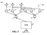
図3は、ここに記載の種々の態様に従って、受信機RFチェーンを備える無線端末における種々のコンポーネントを有するシステム300を示す。いくつかの態様によれば、複数の「合成(compound)」アンテナパターンが可能である。たとえば、システム300は、利得値(G1,1、G2,1、GN,1)をそれぞれ有する利得素子(308、310、312)の第1のセットとそれぞれ結合された複数のアンテナ素子(302、304、306)を含んでいる。利得素子(308、310、312)の第1のセットの出力は、第1の結合回路314に入力される。アンテナ素子(302、304、306)は、利得値(G1,2、G2,2、GN,2)をそれぞれ有する利得素子(308’、310’、312’)の第2のセットともそれぞれ結合されている。利得素子(308’、310’、312’)の第2のセットの出力は、第2の結合回路314’に入力される。それぞれが対応する結合回路を有する利得素子のセットを追加して実装することが可能である。システム300はさらに、切替器316を含み、切替器316は、結合回路(314、314’)のうちの一方の出力のうちの1つを自身と結合し、また、受信機RFチェーンの入力と結合されている。
FIG. 3 illustrates a
各アンテナパターンは、実際的には、N個のアンテナ素子の加重和(weighted sum)によって作成される。異なるアンテナパターンは、それぞれの重み係数、利得素子のセットの利得値(たとえば、(G1,1、G2,1、…、GN,1)、(GN,1、G1,2、…、GN,2))が異なる。重み係数は利得値を指す場合もあり、複素数値であっても実数値であってもよい。利得値は固定であっても、あらかじめ決定されているかプログラム可能であっても、調節可能であってもよい。 Each antenna pattern is actually created by a weighted sum of N antenna elements. Different antenna patterns have different weighting factors, gain values of a set of gain elements (eg, (G 1,1 , G 2,1 ,..., G N, 1 ), (G N, 1 , G 1,2 , ..., GN, 2 )) is different. The weighting factor may indicate a gain value, and may be a complex value or a real value. The gain value may be fixed, predetermined or programmable, or adjustable.
図4は、1つまたは複数の態様による、受信信号を非コヒーレントな様式で復号するための、軟復調/インタリーブプロトコル(soft demodulation and interleaving protocol)の複数回の反復の実行を容易にするシステム400を示す。信号は、表1および表2の実施形態で示されたような連結符号で符号化される。
FIG. 4 is a
連結符号の場合は、生成行列全体を公式化することと、最適な(たとえば、最尤(maximal likelihood))復号アルゴリズムを導出することが可能である。しかしながら、最適復号
アルゴリズムは計算が複雑である。反復復号器402は、連結符号化構造の利点を使って
数回の反復で最適復号器の性能に近づくことができる。有利なことに、複雑さは大幅に軽
減される。
In the case of concatenated codes, it is possible to formulate the entire generator matrix and derive an optimal (eg, maximum likelihood) decoding algorithm. However, the optimal decoding algorithm is computationally complex. The iterative decoder 402 can approach the performance of the optimal decoder in a few iterations using the advantages of the concatenated coding structure. Advantageously, the complexity is greatly reduced.
復号器402は、連結符号入力信号(たとえば、図1で、表1または2に関して説明されたスーパースロットで受信されたストリップシンボル)を受信し、内符号復調器(inner code demodulator)404、インタリーバ406、外符号復調器(outer code demodulator)408、およびデインタリーバ410を利用する軟入力軟出力復調プロトコル(soft-input soft-output demodulation protocol)を起動する。たとえば、複数の情報ビットを含むシンボルのセットが内符号復調器404によって受信され、内符号復調器404はその受信シンボルセットを複数のシンボルサブセットに分割する。復号器402はシンボルサブセットの内符号復調のために複数のアプリオリ値を選択し、内符号復調器404はこのアプリオリ値と内符号生成行列とを用いてシンボルサブセットを復調して、複数の軟情報出力値を生成する。軟情報出力値はインタリーバ406によってインタリーブされ、外符号復調器408によって(たとえば、外符号生成行列を用いて)複数の情報ビットのうちの1つに関連付けられる。デインタリーバ410は、複数の第2の軟情報値を外符号復調器408の出力として計算し、各第2の軟情報値は、情報ビットのうちの1つに対応し、この情報ビットに関連付けられた第1の軟情報値のうちの少なくとも2つを用いて計算される。次に、第2の軟情報値は、受信された入力シンボルの内符号復調の次の反復に用いられるアプリオリ値の新しいセットの決定に利用され、これ以降も同様の過程が図4の環状矢印で示されるように反復される。
The decoder 402 receives a concatenated code input signal (eg, strip symbols received in the superslot described in FIG. 1 with respect to Table 1 or 2), an
一例として表1を考える。まず、受信信号は生成行列がG3,8で与えられる内符号に関して復調され、表1の各行の軟復号値(具体的には、第1行の[u0,u2,u4]の軟値X01、X21、X41、第2行の[u1,u3,u4]の軟値X12、X32、X42、以降も同様)が生成される。これらの軟値は、内符号(たとえば、内符号復調器404)の出力軟値(output soft value)と呼ばれる。 As an example, consider Table 1. First, the received signal is demodulated with respect to the inner code whose generation matrix is given by G 3 and 8 , and the soft decoded values (specifically, [u 0 , u 2 , u 4 ] of the first row) Soft values X01, X21, and X41, soft values X12, X32, and X42 of [u 1 , u 3 , u 4 ] in the second row, and so on) are generated. These soft values are called the output soft values of the inner code (eg, inner code demodulator 404).
外符号復調器408は、任意の所与の情報ビットにさらなる符号化保護を与える。たとえば、ビットu0に関しては、第1、第3、第5、および第7のすべての行が軟値を与えることに注意されたい。これらの軟値は、同一であることが理想的である。しかしながら、受信信号における干渉および雑音により、これらの軟値は、第1の反復ラウンドでは同一にならない可能性がある。インタリーバ406、外符号復調器408、およびデインタリーバ410は、内符号の出力軟値を取得し、外符号の出力軟値を計算する。たとえば、ビットu0に関して、第1、第3、第5、および第7行にある内符号の出力軟値を、それぞれX01、X03、X05、およびX07とする。次に、ビットu0に関して、第1行に対する外符号の出力軟値(Y01とする)が、X01、X03、X05、およびX07から計算される(たとえば、Y01=average(X03,X05,X07))。同様に、ビットu0に関して、第3行に対する外符号の出力軟値(Y03とする)が、X01、X03、X05、およびX07から計算される(たとえば、Y03=average(X01,X05,X07))。別の例では、Y01とY03とを同じに設定することが可能である(たとえば、Y01=Y03=average(X01,X03,X05,X07))。
次に、外符号復調器の出力軟値が、デインタリーブされて内符号復調器404に戻され、これによって内符号復調が改善される。具体的には、この時点で内符号復調器404はオリジナルの受信信号と外符号のデインタリーブされた出力軟値とを考慮に入れて、各行の改善された軟復号値を生成することができる。たとえば、第1行では、内符号復調器404は、オリジナルの受信信号とY01、Y21、Y41とを用い、X01、X21、およびX41の新しいセットを生成する。ここで、Y01、Y21、Y41は、それぞれ、第1行のビットu0、u2、u4に対する外符号の出力軟値であり、X01、X21、およびX41は、それぞれ、第1行のビットu0、u2、u4に対する内符号の出力軟値である。前述の手順が他のすべての行について繰り返されて、内符号の出力軟値の新しいセットが生成される。この内符号の新しい出力軟値によって、インタリーバ406、外符号復調器408、およびデインタリーバ410は、外符号の出力軟値の新しいセットを生成することができる。前述の反復される手順は、特定の終了基準が満たされるまで繰り返される。
Next, the output soft value of the outer code demodulator is deinterleaved back to the
図5〜7を参照して、無線端末でのアンテナ切り替えを容易にするために、受信された連結符号信号に対して反復SISO非コヒーレント復調プロトコルを実行することに関する方法論を説明する。説明を簡単にするために本方法論は一続きの動作として図示および記述されているが、1つまたは複数の実施形態によれば、いくつかの動作はここで図示および記述されている順序と異なる順序で、および/または、他の動作と同時に行われることが可能であり、本方法論は図示および記述されている動作順序に限定されないことを理解されたい。たとえば、当業者であれば理解されるように、代替として方法論は一続きの相互に関連する状態またはイベントとして(たとえば、状態図で)表されることが可能である。さらに、特許請求対象による方法論を実施するためには必ずしも例示されたすべての動作が用いられるわけではない。 With reference to FIGS. 5-7, methodologies relating to performing an iterative SISO non-coherent demodulation protocol on a received concatenated code signal to facilitate antenna switching at a wireless terminal will be described. For simplicity, the methodology is illustrated and described as a sequence of operations, but according to one or more embodiments, some operations differ from the order illustrated and described herein. It should be understood that the methodologies can be performed in sequence and / or concurrently with other operations, and the methodology is not limited to the sequence of operations illustrated and described. For example, as will be appreciated by those skilled in the art, a methodology may alternatively be represented as a series of interrelated states or events (eg, in a state diagram). Moreover, not all illustrated acts may be employed to implement a claimed methodology.
図5は、1つまたは複数の態様による、複数の受信アンテナと単一の受信機チェーンとを有する無線装置でのアンテナ切り替えを実行する方法論500を示す。たとえば、方法500は、図1に関して説明されたアンテナ切り替えを達成するために、図1に関して説明された種々の動作を実行することを容易にする。502では、第1のスーパースロットの第2の送信時間期間にコヒーレント復調プロトコルが実行され、第1のアンテナのSNRが推定される。たとえば、スーパースロットは、ストリップシンボルが送信される第1の時間期間と、非ストリップシンボルが送信される第2の時間期間とを含む。たとえば、図1に関して前述された第1のスーパースロットは、ストリップシンボルを第1の時間期間として含み、残りの時間期間における非ストリップシンボルを第2の時間期間として含む。一態様によれば、第1のスーパースロットの第2の時間期間にパイロット信号が送信される。したがって、無線端末は、受信信号を復号するために、第1のアンテナに対応するチャネルH1を推定し、コヒーレント復調プロトコルを使用する。たとえば、無線装置はパイロットのセットを受信してチャネル推定を導出し、これによって、無線装置は第1のスーパースロットの第2の時間期間に受信された信号のコヒーレント復調を実行する。
FIG. 5 illustrates a
504では、第1のスーパースロットが終了しているかどうか、および/または、第2のスーパースロットの第1の送信時間期間が差し迫っているかどうかの決定が行われる。第1のスーパースロットが終了している場合は、506で、第1のアンテナから第2のアンテナへの切り替えが行われ、それによって、その場合のSNRの評価が行われる。第2のスーパースロットの第1の時間期間において、無線端末は、別のアンテナ(たとえば、第2のスーパースロットの第1のストリップシンボルのアンテナ2と、第2のスーパースロットの第2のストリップシンボルのアンテナ3)に切り替えて信号を受信する。その結果として、チャネルは、先に図1に示されたように、H1から第1のストリップシンボルにおけるH2と第2のストリップシンボルにおけるH3とに変更される。チャネルH2またはH3は、受信アンテナが変更されていることから、チャネルH1と異なることに注意されたい。したがって、第1のスーパースロットで取得されたH1のチャネル推定はチャネルH2またはH3に適用できない。それゆえに、無線端末は、ストリップシンボル内の受信信号を復号するために非コヒーレント復調プロトコルを用いる。かくして、508では、たとえば、非コヒーレント変調方式で変調され、1つまたは複数のストリップシンボルの周波数スペクトル全体に拡散された情報ビットを有する信号が受信される。一例によれば、この1つまたは複数のストリップシンボルは、連結符号を備えるが、これに限定されない。
At 504, a determination is made whether the first superslot has expired and / or whether the first transmission time period of the second superslot is imminent. If the first superslot has been completed, a switch from the first antenna to the second antenna is performed at 506, thereby evaluating the SNR in that case. In the first time period of the second superslot, the wireless terminal transmits another antenna (eg,
510では、第2のスーパースロットの第1の送信時間期間に、少なくとも第2のアンテナのSNRが推定される。第2のスーパースロットの第1の送信時間期間は、たとえば、図1の第2のスーパースロットの先頭に示されたストリップシンボルのような、1つまたは複数のストリップシンボルの継続時間に対応する。512では、第2のスーパースロットの第1の送信時間期間に、非コヒーレント検出プロトコルが実行される。この非コヒーレント検出プロトコルは、第2のスーパースロットの第1の送信時間期間に受信された信号のみを用い、先行する時間期間に受信された信号をまったく用いない。SNRはさらに、少なくとも第2のアンテナの場合に推定される。この非コヒーレント検出プロトコルは、図4に関して前述されたインタリーブ/デインタリーブされた情報ビットを有するプロトコルである。514では、コヒーレント検出時間期間に第1のアンテナに関して推定されたSNRと、非コヒーレントSIS検出時間期間に少なくとも第2のアンテナに関して検出されたSNRとの間で比較が行われる。最後に、516では、無線端末が、514での比較結果に基づいて、最高のSNRを有するアンテナに切り替える。このようにして、無線端末は、スーパースロット(たとえば、11.4ミリ秒)ごとのような頻度で複数の受信アンテナを切り替えることを許可される。 At 510, the SNR of at least the second antenna is estimated during the first transmission time period of the second superslot. The first transmission time period of the second superslot corresponds to the duration of one or more strip symbols, such as the strip symbol shown at the beginning of the second superslot in FIG. At 512, a non-coherent detection protocol is performed during the first transmission time period of the second superslot. This non-coherent detection protocol uses only the signal received during the first transmission time period of the second superslot and does not use any signal received during the preceding time period. The SNR is further estimated at least for the second antenna. This non-coherent detection protocol is a protocol with interleaved / deinterleaved information bits described above with respect to FIG. At 514, a comparison is made between the SNR estimated for the first antenna during the coherent detection time period and the SNR detected for at least the second antenna during the non-coherent SIS detection time period. Finally, at 516, the wireless terminal switches to the antenna with the highest SNR based on the comparison result at 514. In this way, the wireless terminal is allowed to switch between multiple receiving antennas at a frequency such as every superslot (eg, 11.4 milliseconds).
関連する態様によれば、アンテナ切り替えは、複数のアンテナSNRの間の所定のしきい値差の関数である。たとえば、アンテナの切り替えが妥当であるためには、514でのSNRの差が、ある所定のしきい値(たとえば、0.25dB、0.5dB、1dBなど)を超えることが必要とされる。一例によれば、所定のしきい値が0.5dBであって、第1のアンテナのSNRが502でXdBと推定された場合、第1の受信アンテナから第2の受信アンテナへの切り替えを許可するためには、510で推定される第2のアンテナのSNRが、X+0.5dB以上でなければならない。 According to related aspects, antenna switching is a function of a predetermined threshold difference between multiple antenna SNRs. For example, in order for antenna switching to be valid, the SNR difference at 514 needs to exceed a certain predetermined threshold (eg, 0.25 dB, 0.5 dB, 1 dB, etc.). According to one example, if the predetermined threshold is 0.5 dB and the SNR of the first antenna is estimated to be X dB at 502, switching from the first receiving antenna to the second receiving antenna is permitted. In order to do so, the SNR of the second antenna estimated at 510 must be greater than or equal to X + 0.5 dB.
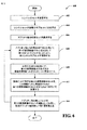
図6は、1つまたは複数の態様による、反復SISO非コヒーレント復調プロトコルを用いて連結符号を復調およびインタリーブすることにより、通信信号を復号する方法論600を示す。たとえば、方法600は、図4に関して前述されたような、受信連結信号の、反復される復調およびインタリーブを容易にする。本方法では、まず602で、複数の情報ビットを含むシンボルのセットが受信される。受信されたシンボルセットは、複数の情報ビットを含み、604で、複数のシンボルサブセットに分割される(各サブセットは、内符号復調プロトコルの入力に対応する)。606では、シンボルサブセットの内符号復調のための、複数の初期アプリオリ値が選択される。608では、初期アプリオリ値と内符号生成行列とを用いて複数の第1の軟情報値を生成することにより、シンボルサブセットが復調される。610では、外符号生成行列を用いることにより、第1の軟情報値のそれぞれが、複数の情報ビットのうちの1つに関連付けられる。612では、複数の第2の軟情報値が外符号復調の出力として計算され、各第2の軟情報値は情報ビットのうちの1つに対応し、この情報ビットに関連付けられた第1の軟情報値のうちの少なくとも2つを用いて計算される。次に、614では、第2の軟情報値を利用して、受信された入力シンボルの内符号復調の次の反復に用いられるアプリオリ値の新しいセットが決定され、初期アプリオリ値は、方法600の608での復調から始まる次の反復のために、この新しいアプリオリ値に置き換えられる。このようにして、方法600は、複雑でなく、効率が高い非コヒーレントSISOプロトコルを用いてストリップシンボルを効果的に復号するために、受信されたストリップシンボル(またはチャネル)に対して実行される、反復される一連の動作を提供する。
FIG. 6 illustrates a
関連する態様によれば、無線端末は、リードマラー符号化(Reed-Muller encoding)手法
を用いて符号化されている信号を受信し、この受信された信号に対して方法600を実行する。さらに、無線端末によって受信された連結符号は、そのような符号化手法に関連付けられた特定の特性を示す。たとえば、受信信号は、無線端末によって受信される前に、外符号と、少なくとも2つのサブブロックを含む内符号との組み合わせを用いて符号化される。したがって、方法600は、図4の復号器402によって実行されるものと同等の復号アルゴリズムの実行を容易にすることが理解されるであろう。
According to related aspects, a wireless terminal receives a signal that has been encoded using a Reed-Muller encoding technique and performs the
他の態様によれば、602で受信されるシンボルセットは、604で、少なくとも2つのサブセットに分割される。さらに、各サブセットに用いられる内符号生成行列は、同じであってよく、あるいは、サブセットごとに異なってもよい。所与の情報ビットに対する第2の軟情報値は、このビットに関連付けられた2つ以上の第1の軟情報値の平均であってよい。 According to another aspect, the symbol set received at 602 is divided at 604 into at least two subsets. Further, the inner code generation matrix used for each subset may be the same or may be different for each subset. The second soft information value for a given information bit may be an average of two or more first soft information values associated with this bit.
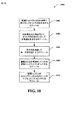
図7は、種々の態様による、無線通信環境において移動アンテナ切り替えを可能にするためにストリップシンボルを符号化する方法論700を示す。702では、外符号生成行列を用いて、ビット情報ベクトルが符号化されてビット行列が生成され、このビット行列は、少なくとも2つの行と、任意の好適な数の列とを備える。704では、内符号生成行列を実装することにより、ビット行列内の各行に対して符号語が生成され、符号語はリードマラー符号を備えるが、これに限定されない。内符号生成行列はビット行列内のすべての行に対して同じであってよく、あるいは、行ごとに異なってもよい。706では、704で生成された符号語が連結されて単一の符号語になる。708では、連結された符号語がいくつかの変調シンボルにマッピングされる。710では、変調シンボルがストリップチャネル内のトーンのサブセットにマッピングされる。変調シンボルがマッピングされるトーンのサブセットは、あらかじめ決められていてよい。さらに、変調シンボルがマッピングされないストリップシンボルトーンが、ストリップシンボルの送信時にゼロエネルギーレベルで送信される。一例によれば、ストリップシンボル内のトーンのうちの約20%以上がゼロエネルギーレベルで送信される。このようにして、方法700は、図1に関して前述された動作のような、種々の符号化動作の実行を容易にするために利用され、そのような動作のいずれかまたはすべてが、方法700と併せて実行される。
FIG. 7 illustrates a
図8は、ここで記載された1つまたは複数の態様による、通信環境において受信チェーンあたり複数の受信アンテナを有する無線端末でのアンテナ切り替えを容易にするシステム800を示す。システム800は一連の相互に関連する機能ブロックとして表され、各機能ブロックは、プロセッサ、ソフトウェア、またはこれらの組み合わせ(たとえば、ファームウェア)によって実装される機能を表す。たとえば、システム800は、図1に関して前述されたような種々の動作を実行するモジュールを提供する。システム800は、第1のスーパースロットの間にコヒーレント復調を実行し、第1のアンテナのSNRを推定するモジュール802を備える。システム800はさらに、第1のスーパースロットが終了しているかどうかを決定するモジュール804と、次の(たとえば、少なくとも第2の)アンテナに切り替えるモジュール806と備える。システム800はさらに、1つまたは複数のビットインタリーブされた連結ストリップシンボルを受信するモジュール808と、少なくとも第2のアンテナのSNRを推定するモジュール810と、少なくとも第2のアンテナについて非コヒーレント復調を実行するモジュール812を備える。システム800はさらに、SNRが推定された各アンテナのSNRを比較するモジュール814と、SNRの比較結果に応じて次のスーパースロットの間に1つまたは複数の信号を受信するアンテナを選択するモジュール816を備える。システム800およびシステム800が備える種々のモジュールは、前述された方法を実施することが可能であること、および/または、ここに記載の種々のシステムに任意の必要な機能性を付与することが可能であることを理解されたい。
FIG. 8 illustrates a
図9は、種々の態様による、反復される軟復調およびインタリーブのアルゴリズムを実行することにより、無線端末で受信された連結符号信号を復号することを容易にするシステム900を示す。システム900は、一連の相互に関連する機能ブロックとして表され、各機能ブロックは、プロセッサ、ソフトウェア、またはこれらの組み合わせ(たとえば、ファームウェア)によって実装される機能を表す。たとえば、システム900は、図4に関して前述されたような種々の動作を実行するモジュールを提供する。システム900は、連結符号を用いて符号化されているシンボルのセットを受信するモジュール902と、受信されたシンボルのセットを複数のサブセットに分割するモジュール904を備える。システム900はさらにアプリオリ値の初期セットを選択するモジュール906を備え、アプリオリ値の初期セットは、内符号生成行列とともに復調するモジュール908によって利用され、これによって、第1の軟情報値のセットが生成される。システム900はさらに、外符号生成行列を用いて第1の軟情報値のそれぞれを受信されたシンボルのセットに含まれる複数の情報ビットのうちの1つに関連付けるモジュール910を備える。計算するモジュール912は、情報ビットに対する第2の軟情報値のセットを、このビットに関連付けられた第1の軟情報値のうちの少なくとも2つを使用して計算する。次に、決定するモジュール914は、第2の軟情報値のセットに応じてアプリオリ値の新しいセットを決定し、モジュール908、910、912、および914によってそれぞれ行われる復調、関連付け、計算、および決定の次の反復のために、アプリオリ値の初期セットを置き換える。システム900およびそれが備える種々のモジュールは前述された方法を実施し、および/または、ここに記載の種々のシステムに任意の必要な機能性を付与することを理解されたい。
FIG. 9 illustrates a
図10は、1つまたは複数の態様による、無線通信環境において無線端末によるアンテナ切り替えを可能にする連結符号ストリップシンボルを符号化することを容易にするシステムを示す。システム1000は一連の相互に関連する機能ブロックとして表され、各機能ブロックは、プロセッサ、ソフトウェア、またはこれらの組み合わせ(たとえば、ファームウェア)によって実装される機能を表す。たとえば、システム1000は、図7に関して前述されたような種々の動作を実行するモジュールを提供する。システム1000は、情報ビットベクトルを外符号で符号化してビット行列を生成するモジュール1002を備える。システム1000はさらに、内符号生成行列を用いてビット行列の各行に対して符号語を生成するモジュール1004を備える。さらに、システム1000は、符号語を連結して単一の符号語にするモジュール1006を備える。連結された符号語をマッピングするモジュール1008によって、連結された符号語がいくつかの変調シンボルにマッピングされる。さらに、変調シンボルをマッピングするモジュール1010は、変調シンボルをストリップシンボル内のトーンのサブセットにマッピングする。システム1000およびシステム1000が備える種々のモジュールは前述された方法を実施し、および/または、ここに記載の種々のシステムに任意の必要な機能性を付与することを理解されたい。
FIG. 10 illustrates a system that facilitates encoding concatenated code strip symbols that enable antenna switching by a wireless terminal in a wireless communication environment, in accordance with one or more aspects.
図11は、本発明に従って実装された、複数のセル(セル1 1102、セルM 1104)を含む例示的通信システム1100を示す。隣接するセル1102、1104は、セル境界領域1168で示されるように、わずかに重なり合っており、これによって、隣接するセルの基地局から送信されている信号の間に信号干渉の可能性がもたらされることに注目されたい。例示的システム1100の各セル1102、1104は、3つのセクタを含む。本発明によれば、複数のセクタに細分されていないセル(N=1)、2つのセクタを有するセル(N=2)、および3つよりも多いセクタを有するセル(N>3)も可能である。セル1102は、第1のセクタ(セクタ1 1110)、第2のセクタ(セクタ2 1112)、および第3のセクタ(セクタ3 1114)を含む。各セクタ1110、1112、1114は、2つのセクタ境界領域を有しており、各境界領域は隣接する2つのセクタの間で共有されている。セクタ境界領域は、隣接するセクタの基地局から送信されている信号の間に信号干渉の可能性をもたらす。線1116は、セクタ1 1110とセクタ2 1112との間のセクタ境界領域を表し、線1118は、セクタ2 1112とセクタ3 1114との間のセクタ境界領域を表し、線1120は、セクタ3 1114とセクタ1 1110との間のセクタ境界領域を表す。同様に、セルM1104は、第1のセクタ(セクタ1 1122)、第2のセクタ(セクタ2 1124)、および第3のセクタ(セクタ3 1126)を含む。線1128は、セクタ1 1122とセクタ2 1124との間のセクタ境界領域を表し、線1130は、セクタ2 1124とセクタ3 1126との間のセクタ境界領域を表し、線1132は、セクタ3 1126とセクタ1 1122との間のセクタ境界領域を表す。セル1 1102は、基地局(BS)(基地局1 1106)と、各セクタ1110、1112、1114内に複数のエンドノード(EN)とを含む。セクタ1 1110は、無線リンク1140、1142を介してBS 1106とそれぞれ結合されたEN(1)1136およびEN(X)1138を含み、セクタ2 1112は、無線リンク1148、1150を介してBS 1106とそれぞれ結合されたEN(1’)1144およびEN(X’)1146を含み、セクタ3 1126は、無線リンク1156、1158を介してBS 1106とそれぞれ結合されたEN(1”)1152およびEN(X”)1154を含む。同様に、セルM 1104は、基地局M 1108と、各セクタ1122、1124、1126内に複数のエンドノード(EN)とを含む。セクタ1 1122は、無線リンク1140’、1142’を介してBS M 1108とそれぞれ結合されたEN(1)1136’およびEN(X)1138’を含み、セクタ2 1124は、無線リンク1148’、1150’を介してBS M 1108とそれぞれ結合されたEN(1’)1144’およびEN(X’)1146’を含み、セクタ3 1126は、無線リンク1156’、1158’を介してBS M 1108とそれぞれ結合されたEN(1”)1152’およびEN(X”)1154’を含む。システム1100はさらに、BS1 1106およびBS M 1108と、それぞれネットワークリンク1162、1164を介して結合されたネットワークノード1160を含む。ネットワークノード1160はまた、ネットワークリンク1166を介して他のネットワークノード(たとえば、他の基地局、AAAサーバノード、中間ノード、ルータなど)およびインターネットとも結合されている。ネットワークリンク1162、1164、1166は、たとえば、光ファイバケーブルである。各エンドノード(たとえば、EN(1)1136)は、たとえば、送信機ならびに受信機を含む無線端末である。無線端末(たとえば、EN(1)1136)は、システム1100内を移動することが可能で、このENが現在位置しているセルにある基地局と無線リンクを介して通信する。無線端末(WT)(たとえば、EN(1)1136)は、基地局(たとえば、BS 1106)および/またはネットワークノード1160を介して、ピアノード(たとえば、システム1100内またはシステム1100の外の、他のWT)と通信する。WT(たとえば、EN(1)1136)は、携帯電話、無線モデム付き携帯情報端末などのような移動通信装置である。本発明によれば、各基地局は、ストリップシンボル期間に、それ以外のシンボル期間(たとえば、非ストリップシンボル期間)でトーンの割り当ておよびトーンホッピングの決定に用いられる方法とは異なる方法を用いて、トーンサブセット割り当てを実行する。無線端末は、本発明のトーンサブセット割り当て方法を、基地局から受信された情報(たとえば、基地局のスロープID、セクタIDの情報)とともに用いて、特定のストリップシンボル期間にデータおよび情報を受信するために用いることができるトーンを決定する。本発明によれば、セクタ間干渉およびセル間干渉を各トーンの全体に拡散させるためのトーンサブセット割り当てシーケンスが構築される。
FIG. 11 shows an
図12は、本発明による例示的な基地局1200を示す。例示的な基地局1200は、セルの各異なるセクタタイプに対して生成される様々なトーンサブセット割り当てシーケンスによって、本発明のトーンサブセット割り当てシーケンスを実行する。基地局1200は、図11のシステム1120の基地局1126、1128のうちの任意の1つとして使用される。基地局1200は、バス1209によって1つに結合されている受信機1202、送信機1204、プロセッサ1206(たとえば、CPU)、入出力インタフェース1208、およびメモリ1210を含み、バス1209を介して各種要素1202、1204、1206、1208、および1210がデータおよび情報を交換する。
FIG. 12 shows an
基地局のセル内の各セクタからの無線端末送信からデータおよび他の信号(たとえば、チャネルレポート)を受信するために、受信機1202と結合されたセクタ化アンテナ(sectorized antenna)1203が用いられる。データおよび他の信号(たとえば、制御信号、パイロット信号、ビーコン信号、スーパースロットの第1の送信時間期間におけるストリップシンボルなど)を基地局のセルの各セクタ内の無線端末1300(図13を参照)に送信するために、送信機1204と結合されたセクタ化アンテナ1205が用いられる。本発明の種々の実施形態では、基地局1200は複数の受信機1202と複数の送信機1204とを用い、たとえば、セクタごとに個別の受信機1202を用い、セクタごとに個別の送信機1204を用いる。プロセッサ1206は、たとえば、汎用中央処理装置(CPU)である。プロセッサ1206は、メモリ1210に記憶された1つまたは複数のルーチン1218からの命令によって基地局1200の動作を制御し、本発明の方法を実施する。入出力インタフェース1208は、(BS 1200を他の基地局、アクセスルータ、AAAサーバノードなどと結合する)他のネットワークノード、他のネットワーク、およびインターネットとの接続を提供する。メモリ1210はルーチン1218およびデータ/情報1220を含む。
A
データ/情報1220は、データ1236、連結符号化情報1238、および無線端末(WT)データ/情報1244を含み、連結符号化情報1238は、ダウンリンクストリップシンボル時間情報1240とダウンリンクトーン情報1242とを含み、無線端末(WT)データ/情報1244は、WT情報の複数のセット(WT 1 情報1246およびWT N 情報1260)を含む。WT情報の各セット(たとえば、WT 1 情報1246)は、データ1248、端末ID 1250、セクタID 1252、アップリンクチャネル情報1254、ダウンリンクチャネル情報1256、およびモード情報1258を含む。
Data /
ルーチン1218は、通信ルーチン1222および基地局制御ルーチン1224を含む。基地局制御ルーチン1224は、ストリップチャネル符号化ルーチンを含み、ストリップチャネル符号化ルーチンは、符号化器1214によって実施される連結符号化ルーチン1228を備える。連結符号化ルーチン1228は、図1に関して前述された動作と同等の符号化動作を実行することを容易にする。
データ1236は、WTへの送信に先立つ符号化のために送信機1204の符号化器1214に送られる送信予定データと、受信後に受信機1202の復号器1212で処理された、WTからの受信データとを含む。ダウンリンクストリップシンボル時間情報1240は、フレーム同期構造情報(たとえば、スーパースロット、ビーコンスロット、およびウルトラスロットの構造情報)と、所与のシンボル期間がストリップシンボル期間かどうかを指定する情報と、ストリップシンボル期間である場合にはストリップシンボル期間のインデックスを指定する情報と、このストリップシンボルが基地局によって使用されるトーンサブセット割り当てシーケンスを切り詰めるためのリセットポイントかどうかを指定する情報とを含む。ダウンリンクトーン情報1242は、基地局1200に割り当てられたキャリア周波数、トーンの数および周波数、ならびにストリップシンボル期間に割り当てられるべきトーンサブセットのセットを含む情報と、他のセル固有およびセクタ固有の値(たとえば、スロープ、スロープインデックス、およびセクタタイプ)とを含む。
Data 1236 includes transmission-scheduled data sent to the
データ1248は、WT 1 1300がピアノードから受信したデータと、ピアノードに送信されることをWT 1 1300が必要とするデータと、ダウンリンクチャネル品質レポートフィードバック情報とを含む。端末ID 1250は、基地局1200が割り当てた、WT 1 1300を識別するIDである。セクタID 1252は、WT 1 1300が動作しているセクタを識別する情報を含む。セクタID 1252は、たとえば、セクタタイプの決定に用いられる。アップリンクチャネル情報1254は、WT 1 1300が使用するチャネルセグメントを識別する情報(たとえば、データ用、要求専用アップリンク制御チャネル用、電力制御用、タイミング制御用などのアップリンクトラヒックチャネルセグメント)を含む。WT 1 1300に割り当てられた各アップリンクチャネルは、1つまたは複数の論理トーンを含み、各論理トーンは、本発明によるアップリンクホッピングシーケンスに従う。ダウンリンクチャネル情報1256は、データおよび/または情報をWT 1 1300へ搬送するチャネルセグメント(たとえば、ユーザデータ用ダウンリンクトラヒックチャネルセグメント)を識別する情報を含む。WT 1 1300に割り当てられた各ダウンリンクチャネルは、1つまたは複数の論理トーンを含み、各論理トーンは、ダウンリンクホッピングシーケンスに従う。モード情報1258は、WT 1 1300の動作状態(たとえば、スリープ、ホールド、オン)を識別する情報を含む。通信ルーチン1222は、基地局1200が種々の通信動作を実行し、種々の通信プロトコルを実施することを制御する。基地局制御ルーチン1224は、基地局の基本機能タスク(たとえば、信号の生成および受信、スケジューリングなど)を実行することと、(ストリップシンボル期間に本発明のトーンサブセット割り当てシーケンスを用いて信号を無線端末へ送信することを含む)本発明の方法の各ステップを実施することと、を行うように基地局1200を制御するために用いられる。
図13は、図11に示されたシステム1100の無線端末(エンドノード)のうちの任意の1つ(たとえば、EN(1)1136)として用いられる例示的な無線端末(エンドノード)1300を示す。無線端末1300は、本発明によるトーンサブセット割り当てシーケンスを実施する。無線端末1300はバス1310によって1つに結合されている(たとえば、図4の復号器402と同等であってよい)復号器1312を含む受信機1302と、符号化器1314を含む送信機1304と、プロセッサ1306と、メモリ1308とを含み、バス1310を介して各種要素1302、1304、1306、1308がデータおよび情報を交換する。基地局1200からの信号を受信するアンテナ1303が受信機1302と結合されている。信号を(たとえば、基地局1200へ)送信するアンテナ1305が送信機1304と結合されている。
FIG. 13 shows an exemplary wireless terminal (end node) 1300 that may be used as any one of the wireless terminals (end nodes) of
プロセッサ1306(たとえば、CPU)は、メモリ1308内のルーチン1320を実行し、データ/情報1322を用いることにより無線端末1300の動作を制御し、本発明の方法を実施する。データ/情報1322は、ユーザデータ1334、ユーザ情報1336、および復調/インタリーブ情報1350を含む。ユーザデータ1334は、送信機1304から基地局1200への送信に先立つ符号化のために符号化器1314に転送されるピアノード宛てデータと、基地局1200から受信され、受信機1302の復号器1312で処理されたデータとを含む。ユーザ情報1336は、アップリンクチャネル情報1338、ダウンリンクチャネル情報1340、端末ID情報1342、基地局ID情報1344、セクタID情報1346、およびモード情報1348を含む。アップリンクチャネル情報1338は、基地局1200への送信時に無線端末1300が使用する、基地局1200によって割り当てられたアップリンクチャネルセグメントを識別する情報を含む。アップリンクチャネルは、アップリンクトラヒックチャネル、専用アップリンク制御チャネル(たとえば、要求チャネル)、電力制御チャネル、およびタイミング制御チャネルを含む。各アップリンクチャネルは、1つまたは複数の論理トーンを含み、各論理トーンは、本発明によるアップリンクトーンホッピングシーケンスに従う。アップリンクホッピングシーケンスは、セルのセクタタイプによって異なり、かつ、隣接セル間で異なる。ダウンリンクチャネル情報1340は、BS 1200がWT 1300へデータ/情報を送信する際に使用されるように、基地局1200によってWT 1300に割り当てられたダウンリンクチャネルセグメントを識別する情報を含む。ダウンリンクチャネルは、ダウンリンクトラヒックチャネルおよび割り当てチャネルを含み、各ダウンリンクチャネルは、1つまたは複数の論理トーンを含み、各論理トーンは、ダウンリンクホッピングシーケンスに従い、ダウンリンクホッピングシーケンスは、セルの各セクタ間で同期される。
The processor 1306 (eg, CPU) executes a routine 1320 in the
ユーザ情報1336はさらに、基地局1200によって割り当てられた識別情報である端末ID情報1342と、WTが通信を確立した特定の基地局1200を識別する基地局ID情報1344と、セルの、WT 1300が現在位置している特定のセクタを識別するセクタID情報1346とを含む。基地局ID情報 1344は、セルスロープ値を与え、セクタID情報1346は、セクタインデックスタイプを与え、セルスロープ値およびセクタインデックスタイプは、本発明によるアップリンクトーンホッピングシーケンスを導出するために使用される。ユーザ情報1336はさらに、WT 1300がスリープモードにあるか、ホールドモードにあるか、オンモードにあるかを識別するモード情報1348を含む。
The
復調/インタリーブ情報1350は、ダウンリンクストリップシンボル時間情報1352およびダウンリンクトーン情報1354を含む。ダウンリンクストリップシンボル時間情報1352は、フレーム同期構造情報(たとえば、スーパースロット、ビーコンスロット、およびウルトラスロットの構造情報)と、所与のシンボル期間がストリップシンボル期間かどうかを指定する情報と、ストリップシンボル期間である場合にはストリップシンボル期間のインデックスを指定する情報と、このストリップシンボルが基地局によって使用されるトーンサブセット割り当てシーケンスを切り詰めるためのリセットポイントかどうかを指定する情報とを含む。ダウンリンクトーン情報1354は、基地局1000に割り当てられたキャリア周波数、トーンの数および周波数、ならびにストリップシンボル期間に割り当てられるべきトーンサブセットのセットを含む情報と、他のセル固有およびセクタ固有の値(たとえば、スロープ、スロープインデックス、およびセクタタイプ)とを含む。
Demodulation / interleave information 1350 includes downlink strip symbol time information 1352 and
ルーチン1320は、通信ルーチン1324および無線端末制御ルーチン1326を含む。通信ルーチン1324は、WT 1300によって使用される種々の通信プロトコルを制御する。無線端末制御ルーチン1326は、受信機1302および送信機1304の制御を含む、無線端末1300の基本機能性を制御する。無線端末制御ルーチン1326は、反復復号ルーチン1328を含む。反復復号ルーチン1328は、ストリップシンボル期間のための非コヒーレント復調ルーチン1330と、連結符号化手法を用いて符号化されている受信ストリップシンボルを復号することを容易にするインタリーブ/デインタリーブルーチン1332とを含む。
The routine 1320 includes a
図14は、例示的な無線通信システム1400を示す。無線通信システム1400は簡単のために、1つの基地局および1つのユーザ装置として描かれている。しかしながら、このシステムは複数の基地局および/または複数のユーザ装置を含むことが可能であり、2つ目以降の基地局および/またはユーザ装置は、以下で説明される例示的基地局およびユーザ装置とほぼ同等であってもよく、あるいは異なっていてもよいことを理解されたい。さらに、この基地局および/またはユーザ装置は、本明細書に記載のシステムおよび/または方法を用いることが可能であることを理解されたい。
FIG. 14 shows an exemplary
図14を参照すると、ダウンリンクでは、アクセスポイント1405において、送信(TX)データプロセッサ1410は、トラヒックデータを受け取り、フォーマット、符号化、インタリーブ、および変調(またはシンボルマッピング)して、変調シンボル(「データシンボル」)を出力する。シンボル変調器1415は、データシンボルおよびパイロットシンボルを受け取って処理し、シンボルのストリームを出力する。シンボル変調器1415は、データシンボルとパイロットシンボルとを多重化し、それらを送信機(TMTR)1420へ出力する。各送信シンボルは、データシンボル、パイロットシンボル、またはゼロの信号値であってよい。パイロットシンボルは、各シンボル期間内に連続的に送信される。パイロットシンボルは、周波数分割多重化(FDM)、直交周波数分割多重化(OFDM)、時分割多重化(TDM)、周波数分割多重化(FDM)、または符号分割多重化(CDM)がなされうる。
Referring to FIG. 14, in the downlink, at an
TMTR1420は、シンボルのストリームを受け取って、1つまたは複数のアナログ信号に変換し、このアナログ信号をさらに調整(たとえば、増幅、フィルタリング、および周波数アップコンバート)して、無線チャネルへの送信に適したダウンリンク信号を生成する。このダウンリンク信号は、アンテナ1425からユーザ装置へ送信される。ユーザ装置1430では、アンテナ1435がダウンリンク信号を受信し、受信信号を受信機(RCVR)1440へ出力する。受信機1440は、受信信号を調整(たとえば、フィルタリング、増幅、および周波数ダウンコンバート)し、調整された信号をデジタイズしてサンプルを取得する。シンボル復調器1445が、受信パイロットシンボルを復調して、チャネル推定のためにプロセッサ1450へ出力する。シンボル復調器1445はさらに、ダウンリンクに対する周波数応答推定をプロセッサ1450から受け取り、受信されたデータシンボルのデータ復調を実行して(送信されたデータシンボルの推定である)データシンボル推定を取得し、このデータシンボル推定をRXデータプロセッサ1455へ出力する。RXデータプロセッサ1455は、データシンボル推定を復調(たとえば、シンボルデマッピング)、デインタリーブ、および復号して、送信されたトラヒックデータを復元する。シンボル復調器1445およびRXデータプロセッサ1455による処理は、それぞれ、アクセスポイント1405におけるシンボル変調器1415およびTXデータプロセッサ1410による処理と相補的である。
アップリンクでは、TXデータプロセッサ1460はトラヒックデータを処理し、データシンボルを出力する。シンボル変調器1465はデータシンボルとパイロットシンボルとを受け取って多重化し、変調を実行し、シンボルのストリームを出力する。送信機1470はシンボルのストリームを受け取って処理し、アップリンク信号を生成する。このアップリンク信号はアンテナ1435からアクセスポイント1405へ送信される。
On the uplink, a
アクセスポイント1405では、ユーザ装置1430からのアップリンク信号はアンテナ1425で受信され、受信機1475で処理されてサンプルが取得される。シンボル復調器1480はこのサンプルを処理し、受信されたパイロットシンボルとアップリンクに対するデータシンボル推定とを出力する。RXデータプロセッサ1485はデータシンボル推定を処理して、ユーザ装置1430から送信されたトラヒックデータを復元する。プロセッサ1490はアップリンク送信を行っているアクティブなユーザ装置のそれぞれについてチャネル推定を実行する。複数のユーザ装置は、アップリンクの各自に割り当てられたパイロットサブキャリアのセットにおいてパイロットを同時に送信し、このパイロットサブキャリアのセットはインタレースされる。
At
プロセッサ1490および1450は、それぞれ、アクセスポイント1405およびユーザ装置1430における動作を指示(たとえば、制御、調整、管理、その他)する。プロセッサ1490および1450は、それぞれ、プログラムコードおよびデータを記憶するメモリ装置(図示せず)に関連付けられる。プロセッサ1490および1450は、ここに記載の方法論のどれでも利用することができる。プロセッサ1490および1450はさらに、それぞれ、アップリンクおよびダウンリンクに対する周波数応答推定およびインパルス応答推定を導出する計算を実行することもできる。
ソフトウェア実装の場合、ここに記載の手法は、ここに記載の各機能を実行するモジュール(たとえば、プロシージャ、関数、その他)を用いて実装されることが可能である。これらのソフトウェアコードは、メモリ装置に記憶され、プロセッサによって実行されることが可能である。メモリ装置は、プロセッサ内に実装されてもよく、プロセッサの外部に実装されてもよい。プロセッサの外部に実装される場合、メモリ装置は、当該技術分野において周知の種々の手段により、プロセッサと通信可能に結合されることが可能である。 For software implementations, the techniques described herein can be implemented using modules (eg, procedures, functions, etc.) that perform the functions described herein. These software codes can be stored in a memory device and executed by a processor. The memory device may be implemented in the processor or may be implemented outside the processor. When implemented external to the processor, the memory device can be communicatively coupled to the processor by various means well known in the art.
以上の記載内容は、1つまたは複数の実施形態の例を含む。前述の諸実施形態を記述する目的のために、構成要素または方法論の考えられるあらゆる組み合わせを記述することはもちろん不可能であるが、当業者であれば理解されるように、種々の実施形態のさらなる多数の組み合わせおよび順列が可能である。したがって、記述された諸実施形態は、添付の特許請求項の趣旨および範囲から逸脱しない、そのようなすべての変更、修正、および変形形態を包含するものとする。さらに、詳細説明または特許請求の範囲のいずれかで用語「含む(includes)」が使用されている限り、そのような用語は、用語「備える(comprising)」と同様に包含的であるものとする。これは、「備える(comprising)」が、特許請求の範囲において移行句として用いられた場合になされる解釈のとおりである。
以下に、本願発明の当初の特許請求の範囲に記載された発明を付記する。
[1]
通信信号を復号する方法であって、
複数の情報ビットを含むシンボルのセットを受信することと;
前記受信されたシンボルのセットを、各サブセットが内符号復調の入力に対応する複数のシンボルサブセットに分割することと;
シンボルの前記各サブセットの前記内符号復調の初期アプリオリ値のセットを選択することと;
シンボルの前記サブセットの前記初期アプリオリ値と内符号生成行列とを用いてシンボルの前記各サブセットを復調して、複数の第1の軟情報値を前記内符号復調の出力として生成することと、
外符号生成行列を用いて、前記第1の軟情報値のそれぞれを前記複数の情報ビットのうちの1つに関連付けることと;
複数の第2の軟情報値を前記外符号復調の出力として計算することと、なお、前記第2の軟情報値の各々は、前記情報ビットのうちの1つに対応し、かつ、前記情報ビットに関連付けられた前記第1の軟情報値のうちの少なくとも2つを用いて計算される;
前記第2の軟情報値と前記外符号生成行列とを用いて、シンボルの前記各サブセットの前記内符号復調のアプリオリ値の新しいセットを決定し、前記初期アプリオリ値を前記新しいアプリオリ値に置き換えることと;
復調、関連付け、計算、および決定の前記各動作を少なくとも1回繰り返すことと;
を備える方法。
[2]
前記復調することは、非コヒーレント検出を利用して前記第1の軟情報値を復調する、[1]に記載の方法。
[3]
所与の情報ビットに対する前記第2の軟情報値は、前記情報ビットに関連付けられた前記少なくとも2つの第1の軟情報値の平均である、[1]に記載の方法。
[4]
前記受信されたシンボルのセットは、少なくとも2つのシンボルサブセットに分割され、前記少なくとも2つのシンボルサブセットの内符号生成行列は同じである、[1]に記載の方法。
[5]
前記内符号は、リードマラー符号を備える、[4]に記載の方法。
[6]
通信信号を復号することを容易にする装置であって、
複数の情報ビットを含むシンボルのセットを受信し、前記受信されたシンボルのセットを複数のシンボルサブセットに分割する受信機と;
前記シンボルの各サブセットの前記内符号復調の初期アプリオリ値のセットを選択する復号器と;
シンボルの前記サブセットの前記初期アプリオリ値と内符号生成行列とを用いてシンボルの前記各サブセットを復調して、複数の第1の軟情報値を生成する内符号復調器と;
外符号生成行列を用いて、前記第1の軟情報値のそれぞれを前記複数の情報ビットのうちの1つに関連付けるインタリーバと;
複数の第2の軟情報値を計算する外符号復調器と、なお、前記第2の軟情報値の各々は、前記情報ビットのうちの1つに対応し、かつ、前記情報ビットに関連付けられた前記第1の軟情報値のうちの少なくとも2つを用いて計算される;
前記第2の軟情報値と前記外符号生成行列とを用いて、シンボルの前記各サブセットの前記内符号復調のアプリオリ値の新しいセットを決定し、シンボルの前記サブセットの復調の次の反復のために、前記初期アプリオリ値を前記新しいアプリオリ値に置き換えるデインタリーバと;
を備える装置。
[7]
前記内符号復調器は、非コヒーレント検出を利用して前記第1の軟情報値を復調する、[6]に記載の装置。
[8]
所与の情報ビットに対する前記第2の軟情報値は、前記情報ビットに関連付けられた前記少なくとも2つの第1の軟情報値の平均である、[6]に記載の装置。
[9]
前記受信されたシンボルのセットは、少なくとも2つのシンボルサブセットに分割され、前記少なくとも2つのシンボルサブセットの内符号生成行列は同じである、[6]に記載の装置。
[10]
前記内符号は、リードマラー符号を備える、[9]に記載の装置。
[11]
無線端末でのアンテナ切り替えを可能にする信号を復号することを容易にする装置であって、
複数の情報ビットを含むシンボルのセットを受信する手段と;
前記受信されたシンボルのセットを、各サブセットが内符号復調の入力に対応する複数のシンボルサブセットに分割する手段と;
シンボルの前記各サブセットの前記内符号復調の初期アプリオリ値のセットを選択する手段と;
シンボルの前記サブセットの前記初期アプリオリ値と内符号生成行列とを用いてシンボルの前記各サブセットを復調して、複数の第1の軟情報値を前記内符号復調の出力として生成する手段と;
外符号生成行列を用いて、前記第1の軟情報値のそれぞれを前記複数の情報ビットのうちの1つに関連付ける手段と;
複数の第2の軟情報値を前記外符号復調の出力として計算する手段と、なお、前記第2の軟情報値の各々は、前記情報ビットのうちの1つに対応し、かつ、前記情報ビットに関連付けられた前記第1の軟情報値のうちの少なくとも2つを用いて計算される;
前記第2の軟情報値と前記外符号生成行列とを用いて、シンボルの前記各サブセットの前記内符号復調のアプリオリ値の新しいセットを決定し、前記初期アプリオリ値を前記新しいアプリオリ値に置き換える手段と;
復調、関連付け、計算、および決定の前記各動作を少なくとも1回繰り返す手段と;
を備える装置。
[12]
前記復調する手段は、非コヒーレント検出を利用して前記第1の軟情報値を復調する、[11]に記載の装置。
[13]
所与の情報ビットに対する前記第2の軟情報値は、前記情報ビットに関連付けられた前記少なくとも2つの第1の軟情報値の平均である、[11]に記載の装置。
[14]
前記受信されたシンボルのセットは、少なくとも2つのシンボルサブセットに分割され、前記少なくとも2つのシンボルサブセットの内符号生成行列は同じである、[11]に記載の装置。
[15]
前記内符号は、リードマラー符号を備える、[14]に記載の装置。
[16]
複数の情報ビットを含むシンボルのセットを受信することと;
前記受信されたシンボルのセットを複数のシンボルサブセットに分割することと;
シンボルの前記各サブセットの前記内符号復調の初期アプリオリ値のセットを選択することと;
シンボルの前記サブセットの前記初期アプリオリ値と内符号生成行列とを用いてシンボルの前記各サブセットを復調して、複数の第1の軟情報値を生成することと;
外符号生成行列を用いて、前記第1の軟情報値のそれぞれを前記複数の情報ビットのうちの1つに関連付けることと;
複数の第2の軟情報値を計算することと、なお、前記第2の軟情報値の各々は、前記情報ビットのうちの1つに対応し、前記情報ビットに関連付けられた前記第1の軟情報値のうちの少なくとも2つを用いて計算される;
前記第2の軟情報値と前記外符号生成行列とを用いて、シンボルの前記各サブセットの前記内符号復調のアプリオリ値の新しいセットを決定し、前記初期アプリオリ値を前記新しいアプリオリ値に置き換えることと;
復調、関連付け、計算、および決定の前記各動作を少なくとも1回繰り返すことと;
を実行するための外実行可能命令(outer-executable instructions)を記憶するコンピュータ可読媒体。
[17]
非コヒーレント検出を利用して前記第1の軟情報値を復調する命令をさらに備える、[16]に記載のコンピュータ可読媒体。
[18]
所与の情報ビットに対する前記第2の軟情報値は、前記情報ビットに関連付けられた前記少なくとも2つの第1の軟情報値の平均である、[16]に記載のコンピュータ可読媒体。
[19]
前記受信されたシンボルのセットは、少なくとも2つのシンボルサブセットに分割され、前記少なくとも2つのシンボルサブセットの内符号生成行列は同じである、[16]に記載のコンピュータ可読媒体。
[20]
前記内符号は、リードマラー符号を備える、[19]に記載のコンピュータ可読媒体。
[21]
無線端末でのアンテナ切り替えを可能にする信号を復号する、コンピュータで実行可能な命令を実行するプロセッサであって、
前記命令は、
複数の情報ビットを含むシンボルのセットを受信することと;
前記受信されたシンボルのセットを複数のシンボルサブセットに分割することと;
シンボルの前記各サブセットの前記内符号復調の初期アプリオリ値のセットを選択することと;
シンボルの前記サブセットの前記初期アプリオリ値と内符号生成行列とを用いてシンボルの前記各サブセットを復調して、複数の第1の軟情報値を生成することと;
外符号生成行列を用いて、前記第1の軟情報値のそれぞれを前記複数の情報ビットのうちの1つに関連付けることと;
複数の第2の軟情報値を計算することと、なお、前記第2の軟情報値の各々は、前記情報ビットのうちの1つに対応し、前記情報ビットに関連付けられた前記第1の軟情報値のうちの少なくとも2つを用いて計算される;
前記第2の軟情報値と前記外符号生成行列とを用いて、シンボルの前記各サブセットの前記内符号復調のアプリオリ値の新しいセットを決定し、前記初期アプリオリ値を前記新しいアプリオリ値に置き換えることと;
復調、関連付け、計算、および決定の前記各動作を少なくとも1回繰り返すことと;
を備える、プロセッサ。
[22]
前記命令は、非コヒーレント検出を利用して前記第1の軟情報値を復調することをさらに備える、[21]に記載のプロセッサ。
[23]
所与の情報ビットに対する前記第2の軟情報値は、前記情報ビットに関連付けられた前記少なくとも2つの第1の軟情報値の平均である、[21]に記載のプロセッサ。
[24]
前記受信されたシンボルのセットは、少なくとも2つのシンボルサブセットに分割され、前記少なくとも2つのシンボルサブセットの内符号生成行列は同じである、[21]に記載のプロセッサ。
[25]
前記内符号は、リードマラー符号を備える、[24]に記載のプロセッサ。
[26]
無線通信環境において、無線端末への送信のためにストリップシンボルを符号化する方法であって、
外符号生成行列を用いて、情報ビットベクトルを外符号で符号化して、ビット行列を生成することと;
内符号生成行列を用いて、前記ビット行列の各行に対して符号語を生成することと;
前記生成された符号語を連結して単一の符号語にすることと;
前記連結された符号語を、いくつかの変調シンボルにマッピングすることと;
前記変調シンボルを前記ストリップシンボル内のトーンのサブセットにマッピングすることと;
を備える方法。
[27]
トーンの前記サブセットは、前記ストリップシンボル内のトーンの所定のセットを備える、[26]に記載の方法。
[28]
変調シンボルがマッピングされない前記ストリップシンボル内のトーンを、ゼロエネルギーレベルで送信することをさらに備える、[26]に記載の方法。
[29]
各行に対する符号語を生成するために用いられる前記内符号生成行列は、各行に対して同じである、[26]に記載の方法。
[30]
前記ビット行列は、少なくとも2つの行を備える、[26]に記載の方法。
[31]
前記内符号生成行列は、リードマラー符号を備える、[26]に記載の方法。
[32]
前記ストリップシンボル内の前記トーンの少なくとも約20%がゼロエネルギーレベルで送信される、[26]に記載の方法。
[33]
無線通信環境において、無線端末への送信のためにストリップシンボルを符号化することを容易にする装置であって、
外符号生成行列を用いて、情報ビットベクトルを外符号で符号化してビット行列を生成し、内符号生成行列を用いて、前記ビット行列の各行に対して符号語を生成し、前記生成された符号語を連結して単一の符号語にする符号化器と;
前記連結された符号語をいくつかの変調シンボルにマッピングし、前記変調シンボルを前記ストリップシンボル内のトーンのサブセットにマッピングするプロセッサと;
前記ストリップシンボルを送信する送信機と;
を備える装置。
[34]
トーンの前記サブセットは、前記ストリップシンボル内のトーンの所定のセットを備える、[33]に記載の装置。
[35]
前記送信機は、変調シンボルがマッピングされない前記ストリップシンボル内のトーンを、ゼロエネルギーレベルで送信する、[33]に記載の装置。
[36]
各行に対する符号語を生成するために用いられる前記内符号生成行列は、各行に対して同じである、[33]に記載の装置。
[37]
前記ビット行列は、少なくとも2つの行を備える、[33]に記載の装置。
[38]
前記内符号生成行列は、リードマラー符号を備える、[33]に記載の装置。
[39]
前記ストリップシンボル内の前記トーンの少なくとも約20%がゼロエネルギーレベルで送信される、[33]に記載の装置。
[40]
無線端末への送信のためにストリップシンボルを符号化することを容易にする装置であって、
外符号生成行列を用いて、情報ビットベクトルを外符号で符号化して、ビット行列を生成する手段と;
内符号生成行列を用いて、前記ビット行列の各行に対して符号語を生成する手段と;
前記生成された符号語を連結して単一の符号語にする手段と;
前記連結された符号語を、いくつかの変調シンボルにマッピングする手段と;
前記変調シンボルを前記ストリップシンボル内のトーンのサブセットにマッピングする手段と;
を備える装置。
[41]
トーンの前記サブセットは、前記ストリップシンボル内のトーンの所定のセットを備える、[40]に記載の装置。
[42]
変調シンボルがマッピングされない前記ストリップシンボル内のトーンを、ゼロエネルギーレベルで送信する手段をさらに備える、[40]に記載の装置。
[43]
各行に対する符号語を生成するために用いられる前記内符号生成行列は、各行に対して同じである、[40]に記載の装置。
[44]
前記ビット行列は、少なくとも2つの行を備える、[40]に記載の装置。
[45]
前記内符号生成行列は、リードマラー符号を備える、[40]に記載の装置。
[46]
前記ストリップシンボル内の前記トーンの少なくとも約20%がゼロエネルギーレベルで送信される、[40]に記載の装置。
[47]
外符号生成行列を用いて、情報ビットベクトルを外符号で符号化して、ビット行列を生成することと;
内符号生成行列を用いて、前記ビット行列の各行に対して符号語を生成することと;
前記生成された符号語を連結して単一の符号語にすることと;
前記連結された符号語を、いくつかの変調シンボルにマッピングすることと;
前記変調シンボルを前記ストリップシンボル内のトーンのサブセットにマッピングすることと;
を実行するための、コンピュータで実行可能な各命令を記憶する、コンピュータ可読媒体。
[48]
トーンの前記サブセットは、前記ストリップシンボル内のトーンの所定のセットを備える、[47]に記載のコンピュータ可読媒体。
[49]
変調シンボルがマッピングされない前記ストリップシンボル内のトーンを、ゼロエネルギーレベルで送信する命令をさらに備える、[47]に記載のコンピュータ可読媒体。
[50]
各行に対する符号語を生成するために用いられる前記内符号生成行列は、各行に対して同じである、[47]に記載のコンピュータ可読媒体。
[51]
前記ビット行列は、少なくとも2つの行を備える、[47]に記載のコンピュータ可読媒体。
[52]
前記内符号生成行列は、リードマラー符号を備える、[47]に記載のコンピュータ可読媒体。
[53]
前記ストリップシンボル内の前記トーンの少なくとも約20%がゼロエネルギーレベルで送信される、[47]に記載のコンピュータ可読媒体。
[54]
無線装置への送信のためにストリップシンボルを符号化する、コンピュータで実行可能な命令を実行するプロセッサであって、
前記命令は、
外符号生成行列を用いて、情報ビットベクトルを外符号で符号化して、ビット行列を生成することと;
内符号生成行列を用いて、前記ビット行列の各行に対して符号語を生成することと;
前記生成された符号語を連結して単一の符号語にすることと;
前記連結された符号語を、いくつかの変調シンボルにマッピングすることと;
前記変調シンボルを前記ストリップシンボル内のトーンのサブセットにマッピングすることと;
を備える、プロセッサ。
[55]
トーンの前記サブセットは、前記ストリップシンボル内のトーンの所定のセットを備える、[54]に記載のプロセッサ。
[56]
前記命令は、変調シンボルがマッピングされない前記ストリップシンボル内のトーンをゼロエネルギーレベルで送信することをさらに備える、[54]に記載のプロセッサ。
[57]
各行に対する符号語を生成するために用いられる前記内符号生成行列は、各行に対して同じである、[47]に記載のコンピュータ可読媒体。
[58]
前記ビット行列は、少なくとも2つの行を備える、[54]に記載のプロセッサ。
[59]
前記内符号生成行列は、リードマラー符号を備える、[54]に記載のプロセッサ。
[60]
前記ストリップシンボル内の前記トーンの約20%以上がゼロエネルギーレベルで送信される、[54]に記載のプロセッサ。
What has been described above includes examples of one or more embodiments. For the purpose of describing the foregoing embodiments, it is of course not possible to describe every conceivable combination of components or methodologies, but as those skilled in the art will appreciate, the various embodiments Many additional combinations and permutations are possible. Accordingly, the described embodiments are intended to embrace all such alterations, modifications and variations that do not depart from the spirit and scope of the appended claims. Further, so long as the term “includes” is used in either the detailed description or in the claims, such term is intended to be inclusive, as well as the term “comprising”. . This is the interpretation that is made when “comprising” is used as a transitional phrase in the claims.
The invention described in the scope of the claims of the present invention is appended below.
[1]
A method for decoding a communication signal, comprising:
Receiving a set of symbols including a plurality of information bits;
Dividing the set of received symbols into a plurality of symbol subsets, each subset corresponding to an input of inner code demodulation;
Selecting a set of initial a priori values for the inner code demodulation of each subset of symbols;
Demodulating each subset of symbols using the initial a priori value of the subset of symbols and an inner code generator matrix to generate a plurality of first soft information values as outputs of the inner code demodulation;
Associating each of the first soft information values with one of the plurality of information bits using an outer code generator matrix;
Calculating a plurality of second soft information values as outputs of the outer code demodulation, wherein each of the second soft information values corresponds to one of the information bits and the information Calculated using at least two of the first soft information values associated with a bit;
Using the second soft information value and the outer code generator matrix to determine a new set of a priori values for the inner code demodulation of each subset of symbols and replacing the initial a priori value with the new a priori value When;
Repeating said operations of demodulation, association, calculation and determination at least once;
A method comprising:
[2]
The method of [1], wherein the demodulating demodulates the first soft information value using non-coherent detection.
[3]
The method of [1], wherein the second soft information value for a given information bit is an average of the at least two first soft information values associated with the information bit.
[4]
The method of [1], wherein the set of received symbols is divided into at least two symbol subsets, and the inner code generation matrix of the at least two symbol subsets is the same.
[5]
The method according to [4], wherein the inner code comprises a Reed-Muller code.
[6]
An apparatus that facilitates decoding a communication signal,
A receiver for receiving a set of symbols including a plurality of information bits and dividing the received set of symbols into a plurality of symbol subsets;
A decoder that selects a set of initial a priori values for the inner code demodulation of each subset of the symbols;
An inner code demodulator that demodulates each subset of symbols using the initial a priori value of the subset of symbols and an inner code generator matrix to generate a plurality of first soft information values;
An interleaver that associates each of the first soft information values with one of the plurality of information bits using an outer code generator matrix;
An outer code demodulator for calculating a plurality of second soft information values, wherein each of the second soft information values corresponds to one of the information bits and is associated with the information bits. Calculated using at least two of the first soft information values;
The second soft information value and the outer code generator matrix are used to determine a new set of a priori values for the inner code demodulation of each subset of symbols, for the next iteration of demodulation of the subset of symbols And a deinterleaver that replaces the initial a priori value with the new a priori value;
A device comprising:
[7]
The apparatus according to [6], wherein the inner code demodulator demodulates the first soft information value using non-coherent detection.
[8]
The apparatus of [6], wherein the second soft information value for a given information bit is an average of the at least two first soft information values associated with the information bit.
[9]
The apparatus of [6], wherein the received set of symbols is divided into at least two symbol subsets, and an inner code generation matrix of the at least two symbol subsets is the same.
[10]
The apparatus according to [9], wherein the inner code includes a Reed-Muller code.
[11]
An apparatus that facilitates decoding a signal that enables antenna switching at a wireless terminal,
Means for receiving a set of symbols including a plurality of information bits;
Means for dividing said received set of symbols into a plurality of symbol subsets, each subset corresponding to an input of inner code demodulation;
Means for selecting a set of initial a priori values for the inner code demodulation of each subset of symbols;
Means for demodulating each subset of symbols using the initial a priori value of the subset of symbols and an inner code generation matrix to generate a plurality of first soft information values as outputs of the inner code demodulation;
Means for associating each of the first soft information values with one of the plurality of information bits using an outer code generator matrix;
Means for calculating a plurality of second soft information values as outputs of the outer code demodulation, wherein each of the second soft information values corresponds to one of the information bits and the information Calculated using at least two of the first soft information values associated with a bit;
Means for determining a new set of a priori values for the inner code demodulation of each subset of symbols using the second soft information value and the outer code generator matrix and replacing the initial a priori value with the new a priori value When;
Means for repeating said operations of demodulation, association, calculation and determination at least once;
A device comprising:
[12]
The apparatus according to [11], wherein the means for demodulating demodulates the first soft information value using non-coherent detection.
[13]
The apparatus of [11], wherein the second soft information value for a given information bit is an average of the at least two first soft information values associated with the information bit.
[14]
The apparatus of [11], wherein the received set of symbols is divided into at least two symbol subsets, and an inner code generation matrix of the at least two symbol subsets is the same.
[15]
The apparatus according to [14], wherein the inner code includes a Reed-Muller code.
[16]
Receiving a set of symbols including a plurality of information bits;
Dividing the set of received symbols into a plurality of symbol subsets;
Selecting a set of initial a priori values for the inner code demodulation of each subset of symbols;
Demodulating each subset of symbols using the initial a priori value of the subset of symbols and an inner code generator matrix to generate a plurality of first soft information values;
Associating each of the first soft information values with one of the plurality of information bits using an outer code generator matrix;
Calculating a plurality of second soft information values, wherein each of the second soft information values corresponds to one of the information bits and the first soft information value associated with the information bits. Calculated using at least two of the soft information values;
Using the second soft information value and the outer code generator matrix to determine a new set of a priori values for the inner code demodulation of each subset of symbols and replacing the initial a priori value with the new a priori value When;
Repeating said operations of demodulation, association, calculation and determination at least once;
A computer-readable medium that stores outer-executable instructions for executing the.
[17]
The computer-readable medium of [16], further comprising instructions for demodulating the first soft information value using non-coherent detection.
[18]
The computer-readable medium of [16], wherein the second soft information value for a given information bit is an average of the at least two first soft information values associated with the information bit.
[19]
The computer-readable medium of [16], wherein the received set of symbols is divided into at least two symbol subsets, and the inner code generation matrix of the at least two symbol subsets is the same.
[20]
The computer-readable medium according to [19], wherein the inner code includes a Reed-Muller code.
[21]
A processor for executing computer-executable instructions for decoding signals enabling antenna switching at a wireless terminal,
The instructions are
Receiving a set of symbols including a plurality of information bits;
Dividing the set of received symbols into a plurality of symbol subsets;
Selecting a set of initial a priori values for the inner code demodulation of each subset of symbols;
Demodulating each subset of symbols using the initial a priori value of the subset of symbols and an inner code generator matrix to generate a plurality of first soft information values;
Associating each of the first soft information values with one of the plurality of information bits using an outer code generator matrix;
Calculating a plurality of second soft information values, wherein each of the second soft information values corresponds to one of the information bits and the first soft information value associated with the information bits. Calculated using at least two of the soft information values;
Using the second soft information value and the outer code generator matrix to determine a new set of a priori values for the inner code demodulation of each subset of symbols and replacing the initial a priori value with the new a priori value When;
Repeating said operations of demodulation, association, calculation and determination at least once;
Comprising a processor.
[22]
The processor of [21], wherein the instructions further comprise demodulating the first soft information value utilizing non-coherent detection.
[23]
The processor of [21], wherein the second soft information value for a given information bit is an average of the at least two first soft information values associated with the information bit.
[24]
The processor of [21], wherein the received set of symbols is divided into at least two symbol subsets, and the inner code generation matrices of the at least two symbol subsets are the same.
[25]
The processor according to [24], wherein the inner code includes a Reed-Muller code.
[26]
A method of encoding strip symbols for transmission to a wireless terminal in a wireless communication environment, comprising:
Encoding an information bit vector with an outer code using an outer code generator matrix to generate a bit matrix;
Generating a codeword for each row of the bit matrix using an inner code generator matrix;
Concatenating the generated codewords into a single codeword;
Mapping the concatenated codeword to a number of modulation symbols;
Mapping the modulation symbols to a subset of tones in the strip symbols;
A method comprising:
[27]
The method of [26], wherein the subset of tones comprises a predetermined set of tones in the strip symbol.
[28]
The method of [26], further comprising transmitting tones in the strip symbol to which no modulation symbol is mapped at a zero energy level.
[29]
The method of [26], wherein the inner code generator matrix used to generate a codeword for each row is the same for each row.
[30]
The method of [26], wherein the bit matrix comprises at least two rows.
[31]
The method according to [26], wherein the inner code generation matrix includes a Reed-Muller code.
[32]
The method of [26], wherein at least about 20% of the tones in the strip symbol are transmitted at a zero energy level.
[33]
An apparatus that facilitates encoding strip symbols for transmission to a wireless terminal in a wireless communication environment, comprising:
A bit matrix is generated by encoding an information bit vector with an outer code using an outer code generation matrix, and a code word is generated for each row of the bit matrix using an inner code generation matrix, and the generated An encoder that concatenates codewords into a single codeword;
A processor that maps the concatenated codeword to a number of modulation symbols and maps the modulation symbols to a subset of tones in the strip symbols;
A transmitter for transmitting the strip symbol;
A device comprising:
[34]
The apparatus of [33], wherein the subset of tones comprises a predetermined set of tones in the strip symbol.
[35]
The apparatus of [33], wherein the transmitter transmits tones in the strip symbol to which no modulation symbol is mapped at a zero energy level.
[36]
The apparatus of [33], wherein the inner code generator matrix used to generate a codeword for each row is the same for each row.
[37]
The apparatus of [33], wherein the bit matrix comprises at least two rows.
[38]
The apparatus according to [33], wherein the inner code generation matrix includes a Reed-Muller code.
[39]
The apparatus of [33], wherein at least about 20% of the tones in the strip symbol are transmitted at a zero energy level.
[40]
An apparatus that facilitates encoding strip symbols for transmission to a wireless terminal comprising:
Means for generating a bit matrix by encoding an information bit vector with an outer code using an outer code generation matrix;
Means for generating a code word for each row of the bit matrix using an inner code generator matrix;
Means for concatenating the generated codewords into a single codeword;
Means for mapping the concatenated codeword to a number of modulation symbols;
Means for mapping the modulation symbols to a subset of tones in the strip symbols;
A device comprising:
[41]
The apparatus of [40], wherein the subset of tones comprises a predetermined set of tones in the strip symbol.
[42]
The apparatus of [40], further comprising means for transmitting a tone in the strip symbol to which no modulation symbol is mapped at a zero energy level.
[43]
The apparatus of [40], wherein the inner code generator matrix used to generate a codeword for each row is the same for each row.
[44]
The apparatus of [40], wherein the bit matrix comprises at least two rows.
[45]
The apparatus according to [40], wherein the inner code generation matrix includes a Reed-Muller code.
[46]
The apparatus of [40], wherein at least about 20% of the tones in the strip symbol are transmitted at a zero energy level.
[47]
Encoding an information bit vector with an outer code using an outer code generator matrix to generate a bit matrix;
Generating a codeword for each row of the bit matrix using an inner code generator matrix;
Concatenating the generated codewords into a single codeword;
Mapping the concatenated codeword to a number of modulation symbols;
Mapping the modulation symbols to a subset of tones in the strip symbols;
A computer-readable medium that stores computer-executable instructions for executing
[48]
The computer-readable medium of [47], wherein the subset of tones comprises a predetermined set of tones in the strip symbol.
[49]
[47] The computer-readable medium of [47], further comprising instructions for transmitting tones in the strip symbols to which modulation symbols are not mapped at a zero energy level.
[50]
The computer readable medium of [47], wherein the inner code generator matrix used to generate the codeword for each row is the same for each row.
[51]
The computer-readable medium of [47], wherein the bit matrix comprises at least two rows.
[52]
The computer readable medium according to [47], wherein the inner code generation matrix comprises a Reed-Muller code.
[53]
The computer-readable medium of [47], wherein at least about 20% of the tones in the strip symbol are transmitted at a zero energy level.
[54]
A processor for executing computer-executable instructions for encoding strip symbols for transmission to a wireless device comprising:
The instructions are
Encoding an information bit vector with an outer code using an outer code generator matrix to generate a bit matrix;
Generating a codeword for each row of the bit matrix using an inner code generator matrix;
Concatenating the generated codewords into a single codeword;
Mapping the concatenated codeword to a number of modulation symbols;
Mapping the modulation symbols to a subset of tones in the strip symbols;
Comprising a processor.
[55]
The processor of [54], wherein the subset of tones comprises a predetermined set of tones in the strip symbol.
[56]
The processor of [54], wherein the instructions further comprise transmitting tones in the strip symbol to which no modulation symbol is mapped at a zero energy level.
[57]
The computer readable medium of [47], wherein the inner code generator matrix used to generate the codeword for each row is the same for each row.
[58]
The processor of [54], wherein the bit matrix comprises at least two rows.
[59]
The processor according to [54], wherein the inner code generation matrix includes a Reed-Muller code.
[60]
The processor of [54], wherein about 20% or more of the tones in the strip symbol are transmitted at a zero energy level.
Claims (35)
外符号生成行列を用いて、情報ビットベクトルを外符号で符号化して、ビット行列を生成することと;
内符号生成行列を用いて、前記ビット行列の各行に対して符号語を生成することと;
前記生成された符号語を連結して単一の符号語にすることと;
前記連結された符号語を、いくつかの変調シンボルにマッピングすることと;
前記変調シンボルを前記ストリップシンボル内のトーンのサブセットにマッピングすることと;
を備える方法。A method of encoding strip symbols for transmission to a wireless terminal in a wireless communication environment, comprising:
Encoding an information bit vector with an outer code using an outer code generator matrix to generate a bit matrix;
Generating a codeword for each row of the bit matrix using an inner code generator matrix;
Concatenating the generated codewords into a single codeword;
Mapping the concatenated codeword to a number of modulation symbols;
Mapping the modulation symbols to a subset of tones in the strip symbols;
A method comprising:
外符号生成行列を用いて、情報ビットベクトルを外符号で符号化してビット行列を生成し、内符号生成行列を用いて、前記ビット行列の各行に対して符号語を生成し、前記生成された符号語を連結して単一の符号語にする符号化器と;
前記連結された符号語をいくつかの変調シンボルにマッピングし、前記変調シンボルを前記ストリップシンボル内のトーンのサブセットにマッピングするプロセッサと;
前記ストリップシンボルを送信する送信機と;
を備える装置。An apparatus that facilitates encoding strip symbols for transmission to a wireless terminal in a wireless communication environment, comprising:
A bit matrix is generated by encoding an information bit vector with an outer code using an outer code generation matrix, and a code word is generated for each row of the bit matrix using an inner code generation matrix, and the generated An encoder that concatenates codewords into a single codeword;
A processor that maps the concatenated codeword to a number of modulation symbols and maps the modulation symbols to a subset of tones in the strip symbols;
A transmitter for transmitting the strip symbol;
A device comprising:
外符号生成行列を用いて、情報ビットベクトルを外符号で符号化して、ビット行列を生成する手段と;
内符号生成行列を用いて、前記ビット行列の各行に対して符号語を生成する手段と;
前記生成された符号語を連結して単一の符号語にする手段と;
前記連結された符号語を、いくつかの変調シンボルにマッピングする手段と;
前記変調シンボルを前記ストリップシンボル内のトーンのサブセットにマッピングする手段と;
を備える装置。An apparatus that facilitates encoding strip symbols for transmission to a wireless terminal comprising:
Means for generating a bit matrix by encoding an information bit vector with an outer code using an outer code generation matrix;
Means for generating a code word for each row of the bit matrix using an inner code generator matrix;
Means for concatenating the generated codewords into a single codeword;
Means for mapping the concatenated codeword to a number of modulation symbols;
Means for mapping the modulation symbols to a subset of tones in the strip symbols;
A device comprising:
内符号生成行列を用いて、前記ビット行列の各行に対して符号語を生成することと;
前記生成された符号語を連結して単一の符号語にすることと;
前記連結された符号語を、いくつかの変調シンボルにマッピングすることと;
前記変調シンボルを前記ストリップシンボル内のトーンのサブセットにマッピングすることと;
を実行するための、コンピュータで実行可能な各命令を記憶する、コンピュータ可読媒体。Encoding an information bit vector with an outer code using an outer code generator matrix to generate a bit matrix;
Generating a codeword for each row of the bit matrix using an inner code generator matrix;
Concatenating the generated codewords into a single codeword;
Mapping the concatenated codeword to a number of modulation symbols;
Mapping the modulation symbols to a subset of tones in the strip symbols;
A computer-readable medium that stores computer-executable instructions for executing
前記命令は、
外符号生成行列を用いて、情報ビットベクトルを外符号で符号化して、ビット行列を生成することと;
内符号生成行列を用いて、前記ビット行列の各行に対して符号語を生成することと;
前記生成された符号語を連結して単一の符号語にすることと;
前記連結された符号語を、いくつかの変調シンボルにマッピングすることと;
前記変調シンボルを前記ストリップシンボル内のトーンのサブセットにマッピングすることと;
を備える、プロセッサ。A processor for executing computer-executable instructions for encoding strip symbols for transmission to a wireless device comprising:
The instructions are
Encoding an information bit vector with an outer code using an outer code generator matrix to generate a bit matrix;
Generating a codeword for each row of the bit matrix using an inner code generator matrix;
Concatenating the generated codewords into a single codeword;
Mapping the concatenated codeword to a number of modulation symbols;
Mapping the modulation symbols to a subset of tones in the strip symbols;
Comprising a processor.
Applications Claiming Priority (3)
| Application Number | Priority Date | Filing Date | Title |
|---|---|---|---|
| US11/487,032 US8225186B2 (en) | 2006-07-14 | 2006-07-14 | Ecoding and decoding methods and apparatus for use in a wireless communication system |
| US11/487,032 | 2006-07-14 | ||
| PCT/US2007/073556 WO2008024567A1 (en) | 2006-07-14 | 2007-07-14 | Ecoding and decoding methods and apparatus for use in a wireless communication system |
Publications (2)
| Publication Number | Publication Date |
|---|---|
| JP2009544257A JP2009544257A (en) | 2009-12-10 |
| JP5123301B2 true JP5123301B2 (en) | 2013-01-23 |
Family
ID=38814637
Family Applications (1)
| Application Number | Title | Priority Date | Filing Date |
|---|---|---|---|
| JP2009520938A Expired - Fee Related JP5123301B2 (en) | 2006-07-14 | 2007-07-14 | Encoding and decoding method and apparatus for use in a wireless communication system |
Country Status (5)
| Country | Link |
|---|---|
| US (2) | US8225186B2 (en) |
| EP (1) | EP2041905A1 (en) |
| JP (1) | JP5123301B2 (en) |
| TW (1) | TW200816735A (en) |
| WO (1) | WO2008024567A1 (en) |
Families Citing this family (23)
| Publication number | Priority date | Publication date | Assignee | Title |
|---|---|---|---|---|
| US7826807B2 (en) * | 2005-03-09 | 2010-11-02 | Qualcomm Incorporated | Methods and apparatus for antenna control in a wireless terminal |
| US8325826B2 (en) * | 2005-03-09 | 2012-12-04 | Qualcomm Incorporated | Methods and apparatus for transmitting signals facilitating antenna control |
| US8225186B2 (en) * | 2006-07-14 | 2012-07-17 | Qualcomm Incorporated | Ecoding and decoding methods and apparatus for use in a wireless communication system |
| JP2008236382A (en) * | 2007-03-20 | 2008-10-02 | Toshiba Corp | Radio communication system |
| US8495232B2 (en) * | 2007-07-10 | 2013-07-23 | Qualcomm Incorporated | Methods and apparatus for supporting broadcast communications in a peer to peer network |
| US8861418B2 (en) * | 2007-07-10 | 2014-10-14 | Qualcomm Incorporated | Methods and apparatus for supporting group communications with data re-transmission support |
| US8694662B2 (en) * | 2007-07-10 | 2014-04-08 | Qualcomm Incorporated | Method and apparatus for communicating transmission requests to members of a group and/or making group related transmission decisions |
| US7961698B2 (en) * | 2007-07-10 | 2011-06-14 | Qualcomm Incorporated | Methods and apparatus for controlling interference to broadcast signaling in a peer to peer network |
| US9252813B2 (en) * | 2009-05-27 | 2016-02-02 | Novelsat Ltd. | Iterative decoding of LDPC codes with iteration scheduling |
| JP5505178B2 (en) * | 2009-11-02 | 2014-05-28 | 日本電気株式会社 | RADIO COMMUNICATION DEVICE, RADIO COMMUNICATION DEVICE RECEIVER LEVEL DETERMINING METHOD AND PROGRAM |
| TWI474632B (en) * | 2011-08-24 | 2015-02-21 | Realtek Semiconductor Corp | Wireless communication circuit supporting antenna diversity and related computer program product |
| US8767691B2 (en) * | 2011-09-19 | 2014-07-01 | Alcatel Lucent | Method and apparatus for scheduling transmissions for antenna arrays |
| US9294224B2 (en) * | 2011-09-28 | 2016-03-22 | Intel Corporation | Maximum-likelihood decoder in a memory controller for synchronization |
| US9264182B2 (en) | 2012-09-13 | 2016-02-16 | Novelsat Ltd. | Iterative receiver loop |
| US8873665B2 (en) * | 2012-11-21 | 2014-10-28 | Intel Mobile Communications GmbH | Communication devices and methods for receiving data |
| US10313053B2 (en) * | 2013-08-23 | 2019-06-04 | Myriota Pty Ltd | Enhanced automatic identification system |
| US9862149B2 (en) | 2014-08-29 | 2018-01-09 | Microsoft Technology Licensing, Llc | Print bureau interface for three-dimensional printing |
| US10374765B2 (en) * | 2016-12-15 | 2019-08-06 | Qualcomm Incorporated | Quantized K-resource element row-column interleaver |
| DE102017100076A1 (en) * | 2017-01-04 | 2018-07-05 | Sennheiser Electronic Gmbh & Co. Kg | Method for low-latency audio transmission in an LTE network |
| CN111543011B (en) | 2018-01-29 | 2022-01-14 | 中兴通讯股份有限公司 | Method and apparatus for generating a spreading sequence codebook |
| CN112448724B (en) * | 2019-08-29 | 2023-07-07 | 华为技术有限公司 | Data coding method and device |
| US11356119B2 (en) * | 2019-12-17 | 2022-06-07 | Qualcomm Incorporated | Noncoherent wireless communication using modified Reed Muller codes |
| US11374686B2 (en) * | 2020-02-04 | 2022-06-28 | Qualcomm Incorporated | Parity check bits for non-coherent communication |
Family Cites Families (69)
| Publication number | Priority date | Publication date | Assignee | Title |
|---|---|---|---|---|
| JPH0191447A (en) | 1987-10-02 | 1989-04-11 | Matsushita Electric Ind Co Ltd | Semiconductor memory cell |
| CA2080124C (en) * | 1991-02-08 | 2000-09-19 | Heinz Lindenmeier | Antenna diversity receiving system for eliminating reception interference in mobile television signal reception |
| US5507035A (en) | 1993-04-30 | 1996-04-09 | International Business Machines Corporation | Diversity transmission strategy in mobile/indoor cellula radio communications |
| WO1995007581A1 (en) | 1993-09-10 | 1995-03-16 | Deutsche Thomson-Brandt Gmbh | Method for the transmission of reference signals in an ofdm system |
| JP3235041B2 (en) | 1993-11-10 | 2001-12-04 | 日本電信電話株式会社 | TDD wireless communication system |
| US5911120A (en) | 1995-09-08 | 1999-06-08 | At&T Wireless Services | Wireless communication system having mobile stations establish a communication link through the base station without using a landline or regional cellular network and without a call in progress |
| JPH09162850A (en) | 1995-12-14 | 1997-06-20 | Matsushita Electric Ind Co Ltd | Digital cordless telephone set |
| US5910434A (en) | 1995-12-15 | 1999-06-08 | Systemix, Inc. | Method for obtaining retroviral packaging cell lines producing high transducing efficiency retroviral supernatant |
| GB2311693B (en) | 1996-03-29 | 2000-06-21 | Nokia Mobile Phones Ltd | Antenna selection control circuitry |
| US6023783A (en) * | 1996-05-15 | 2000-02-08 | California Institute Of Technology | Hybrid concatenated codes and iterative decoding |
| JP3278575B2 (en) | 1996-05-31 | 2002-04-30 | 沖電気工業株式会社 | Diversity receiver circuit |
| US5859840A (en) | 1996-05-31 | 1999-01-12 | Qualcomm Incorporated | Spread spectrum communication system which defines channel groups comprising selected channels that are additional to a primary channel and transmits group messages during call set up |
| KR0173101B1 (en) * | 1996-08-14 | 1999-03-30 | 양승택 | Walsh-quadrature phase shift keying chip modulating apparatus for direct sequence spread spectrum communication |
| US6377610B1 (en) * | 1997-04-25 | 2002-04-23 | Deutsche Telekom Ag | Decoding method and decoding device for a CDMA transmission system for demodulating a received signal available in serial code concatenation |
| US5907577A (en) * | 1997-02-06 | 1999-05-25 | At&T Wireless Services | Delay compensation |
| US5938787A (en) | 1997-03-27 | 1999-08-17 | Ericsson Inc. | Communications systems and methods employing code rate partitioning with nonorthogonal modulation |
| US6172970B1 (en) * | 1997-05-05 | 2001-01-09 | The Hong Kong University Of Science And Technology | Low-complexity antenna diversity receiver |
| JP3724940B2 (en) | 1998-01-08 | 2005-12-07 | 株式会社東芝 | OFDM diversity receiver |
| US6925107B2 (en) * | 1998-03-06 | 2005-08-02 | Deutsche Telekom Ag | Decoding method and decoding device for a CDMA transmission system for demodulating a received signal available in serial code concatenation |
| ES2259227T3 (en) | 1998-04-03 | 2006-09-16 | Agere Systems Inc. | ITERATIVE SIGNAL DECODIFICATION. |
| US6625219B1 (en) | 1999-02-26 | 2003-09-23 | Tioga Technologies, Ltd. | Method and apparatus for encoding/framing for modulated signals over impulsive channels |
| KR100429545B1 (en) | 1999-08-17 | 2004-04-28 | 삼성전자주식회사 | Method for communicating scrambling code id in mobile communication system |
| JP2001056689A (en) | 1999-08-18 | 2001-02-27 | Nok Vibracoustic Kk | Sound absorbing material |
| EP1091447A1 (en) | 1999-10-07 | 2001-04-11 | Siemens Aktiengesellschaft | Antenna system, in particular for use in a mobile phone handset, and corresponding control method |
| GB9925896D0 (en) | 1999-11-03 | 1999-12-29 | Koninkl Philips Electronics Nv | Radio communication system |
| JP3696013B2 (en) | 1999-11-30 | 2005-09-14 | 株式会社豊田中央研究所 | Diversity receiving system for multicarrier modulation and diversity receiving apparatus for multicarrier modulation |
| US6377814B1 (en) * | 2000-02-07 | 2002-04-23 | Qualcomm Incorporated | Method and apparatus for supervising transmit power in a high data rate system |
| US6297691B1 (en) | 2000-06-09 | 2001-10-02 | Rosemount Inc. | Method and apparatus for demodulating coherent and non-coherent modulated signals |
| CA2421956C (en) * | 2000-09-13 | 2007-01-09 | Interdigital Technology Corporation | Third generation fdd modem interleaver |
| US6638965B2 (en) * | 2000-11-01 | 2003-10-28 | Boehringer Ingelheim Pharma Kg | Substituted indolinones, preparation thereof and their use as pharmaceutical compositions |
| US20020085641A1 (en) * | 2000-12-29 | 2002-07-04 | Motorola, Inc | Method and system for interference averaging in a wireless communication system |
| KR100361033B1 (en) | 2001-01-16 | 2003-01-24 | 한국과학기술원 | Multicarrier DS/CDMA system using a turbo code with nonuniform repetition coding |
| US6771706B2 (en) * | 2001-03-23 | 2004-08-03 | Qualcomm Incorporated | Method and apparatus for utilizing channel state information in a wireless communication system |
| US7072413B2 (en) * | 2001-05-17 | 2006-07-04 | Qualcomm, Incorporated | Method and apparatus for processing data for transmission in a multi-channel communication system using selective channel inversion |
| JP2003023411A (en) * | 2001-07-09 | 2003-01-24 | Victor Co Of Japan Ltd | Orthogonal frequency-division multiplex signal generator, and orthogonal frequency-division multiplex signal decoder |
| JP2003101504A (en) * | 2001-09-21 | 2003-04-04 | Sony Corp | Transmission apparatus and method, communication system, recording medium and program |
| US6968021B1 (en) * | 2001-09-24 | 2005-11-22 | Rockwell Collins | Synchronization method and apparatus for modems based on jointly iterative turbo demodulation and decoding |
| US7146553B2 (en) | 2001-11-21 | 2006-12-05 | Infinera Corporation | Error correction improvement for concatenated codes |
| KR100421371B1 (en) | 2002-02-19 | 2004-03-06 | 엘지전자 주식회사 | Adaptive modulation and coding method for mobile communication system |
| US7088793B1 (en) * | 2002-04-17 | 2006-08-08 | Rockwell Collins, Inc. | Equalizer for complex modulations in very noisy environments |
| US6847678B2 (en) * | 2002-04-25 | 2005-01-25 | Raytheon Company | Adaptive air interface waveform |
| US7184772B2 (en) * | 2002-07-01 | 2007-02-27 | Samsung Electronics Co., Ltd. | Wireless network using multiple channel assignment messages and method of operation |
| JP3732830B2 (en) * | 2002-10-10 | 2006-01-11 | 松下電器産業株式会社 | Multicarrier transmission apparatus and multicarrier transmission method |
| JP2004146982A (en) * | 2002-10-23 | 2004-05-20 | Sony Corp | Coder, coding method, program for the coding method, decoder, decoding method, and program for the decoding method |
| JP4088133B2 (en) | 2002-10-24 | 2008-05-21 | 富士通株式会社 | Read channel decoder, read channel decoding method and read channel decoding program |
| US20040081131A1 (en) * | 2002-10-25 | 2004-04-29 | Walton Jay Rod | OFDM communication system with multiple OFDM symbol sizes |
| US7058873B2 (en) * | 2002-11-07 | 2006-06-06 | Carnegie Mellon University | Encoding method using a low density parity check code with a column weight of two |
| KR100542090B1 (en) * | 2002-12-16 | 2006-01-11 | 한국전자통신연구원 | Method for controlling error, designing medium access control frame and registering terminal in wireless communication system and recording medium |
| US7016690B2 (en) | 2003-02-10 | 2006-03-21 | Flarion Technologies, Inc. | Methods and apparatus for updating mobile node location information |
| US7813322B2 (en) * | 2003-02-19 | 2010-10-12 | Qualcomm Incorporated | Efficient automatic repeat request methods and apparatus |
| CN1527512A (en) | 2003-03-06 | 2004-09-08 | 北京三星通信技术研究有限公司 | Training sign generating and transmitting method in orthogonal frequency-division multiplexing system |
| EP1618748B1 (en) | 2003-04-23 | 2016-04-13 | QUALCOMM Incorporated | Methods and apparatus of enhancing performance in wireless communication systems |
| US7693032B2 (en) * | 2004-02-13 | 2010-04-06 | Neocific, Inc. | Methods and apparatus for multi-carrier communication systems with adaptive transmission and feedback |
| US7558554B2 (en) * | 2004-02-24 | 2009-07-07 | Broadcom Corporation | Method and system for antenna selection diversity with prediction |
| JP3806763B2 (en) * | 2004-03-08 | 2006-08-09 | 独立行政法人情報通信研究機構 | Base station and communication method |
| US7684372B2 (en) | 2004-05-04 | 2010-03-23 | Ipwireless, Inc. | Signaling MIMO allocations |
| US8000377B2 (en) * | 2004-05-24 | 2011-08-16 | General Dynamics C4 Systems, Inc. | System and method for variable rate multiple access short message communications |
| KR200369299Y1 (en) | 2004-08-30 | 2004-12-04 | 이병재 | Cable Reel for Supply of Electric Power |
| US7444119B2 (en) * | 2004-11-30 | 2008-10-28 | Symbol Technologies, Inc. | Method for sharing antennas of a wireless device |
| US7590195B2 (en) * | 2005-02-23 | 2009-09-15 | Nec Laboratories America, Inc. | Reduced-complexity multiple-input multiple-output (MIMO) channel detection via sequential Monte Carlo |
| US7826807B2 (en) | 2005-03-09 | 2010-11-02 | Qualcomm Incorporated | Methods and apparatus for antenna control in a wireless terminal |
| US8325826B2 (en) | 2005-03-09 | 2012-12-04 | Qualcomm Incorporated | Methods and apparatus for transmitting signals facilitating antenna control |
| US7471702B2 (en) | 2005-03-09 | 2008-12-30 | Qualcomm Incorporated | Methods and apparatus for implementing, using, transmitting, and/or receiving signals at least some of which include intentional null tones |
| US7609614B2 (en) * | 2005-10-20 | 2009-10-27 | Trellis Phase Communications, Lp | Uplink modulation and receiver structures for asymmetric OFDMA systems |
| US7602838B2 (en) * | 2005-12-22 | 2009-10-13 | Telefonaktiebolaget Lm Ericsson (Publ) | Linear turbo equalization using despread values |
| US7720485B2 (en) * | 2006-07-14 | 2010-05-18 | Qualcomm Incorporated | Methods and apparatus related to assignment in a wireless communications system |
| US7724853B2 (en) * | 2006-07-14 | 2010-05-25 | Qualcomm Incorporated | Enabling mobile switched antennas |
| US8225186B2 (en) * | 2006-07-14 | 2012-07-17 | Qualcomm Incorporated | Ecoding and decoding methods and apparatus for use in a wireless communication system |
| JP4934107B2 (en) * | 2007-06-27 | 2012-05-16 | 京セラミタ株式会社 | Traction power transmission device and image forming apparatus equipped with the same |
-
2006
- 2006-07-14 US US11/487,032 patent/US8225186B2/en active Active
-
2007
- 2007-07-14 JP JP2009520938A patent/JP5123301B2/en not_active Expired - Fee Related
- 2007-07-14 WO PCT/US2007/073556 patent/WO2008024567A1/en active Application Filing
- 2007-07-14 EP EP07840412A patent/EP2041905A1/en not_active Withdrawn
- 2007-07-16 TW TW096125918A patent/TW200816735A/en unknown
-
2012
- 2012-06-29 US US13/537,171 patent/US8539323B2/en active Active
Also Published As
| Publication number | Publication date |
|---|---|
| US8539323B2 (en) | 2013-09-17 |
| US20120269282A1 (en) | 2012-10-25 |
| TW200816735A (en) | 2008-04-01 |
| US20080260073A1 (en) | 2008-10-23 |
| US8225186B2 (en) | 2012-07-17 |
| JP2009544257A (en) | 2009-12-10 |
| EP2041905A1 (en) | 2009-04-01 |
| WO2008024567A1 (en) | 2008-02-28 |
Similar Documents
| Publication | Publication Date | Title |
|---|---|---|
| JP5123301B2 (en) | Encoding and decoding method and apparatus for use in a wireless communication system | |
| US8477593B2 (en) | Method and apparatus for sending signaling for data transmission in a wireless communication system | |
| US20220191080A1 (en) | Wireless communications device, infrastructure equipment and methods | |
| JP4903867B2 (en) | Enabling the mobile switching antenna | |
| US20090046702A1 (en) | Secondary synchronization codebook for e-utran | |
| US9003268B2 (en) | Generation and application of a sub-codebook of an error control coding codebook | |
| KR102417324B1 (en) | A Simplified Detection Scheme for Spatial Modulation and Space-Time Block Coding with Antenna Selection | |
| CN106922213B (en) | Method, device and equipment for transmitting information | |
| JP5706527B2 (en) | Generation and application of subcodebook for error control coding codebook | |
| WO2021254207A1 (en) | Data frame sending method, data frame receiving method, and communication apparatus | |
| Haghighat et al. | On the performance of IDMA-based non-orthogonal multiple access schemes | |
| CN101496368A (en) | Method and apparatus for sending signaling for data transmission in a wireless communication system | |
| JP5995203B2 (en) | Radio receiving apparatus and radio receiving method | |
| CN108449305B (en) | Multi-user multiplexing method suitable for downlink transmission of wireless communication system | |
| CN114696943B (en) | Sequence transmission method, receiving method, terminal, network device and storage medium | |
| CN106656413B (en) | Broadcast channel data transmitting and receiving method | |
| JP4754324B2 (en) | Wireless communication apparatus and communication control method | |
| Chen | Research on the 4G Mobile Communication Systems Link Scheme Based on MIMO Systems | |
| JP6253121B2 (en) | Generation and application of subcodebook for error control coding codebook | |
| JP5886993B2 (en) | Generation and application of subcodebook for error control coding codebook | |
| Marzo | Study of 5G New Radio and performance analysis through numerical simulation of the Physical Downlink Control Channel | |
| WO2009020297A1 (en) | Method of transmitting data in wireless communication system |
Legal Events
| Date | Code | Title | Description |
|---|---|---|---|
| A977 | Report on retrieval |
Free format text: JAPANESE INTERMEDIATE CODE: A971007 Effective date: 20111108 |
|
| A131 | Notification of reasons for refusal |
Free format text: JAPANESE INTERMEDIATE CODE: A131 Effective date: 20111115 |
|
| A601 | Written request for extension of time |
Free format text: JAPANESE INTERMEDIATE CODE: A601 Effective date: 20120214 |
|
| A602 | Written permission of extension of time |
Free format text: JAPANESE INTERMEDIATE CODE: A602 Effective date: 20120221 |
|
| A601 | Written request for extension of time |
Free format text: JAPANESE INTERMEDIATE CODE: A601 Effective date: 20120315 |
|
| A602 | Written permission of extension of time |
Free format text: JAPANESE INTERMEDIATE CODE: A602 Effective date: 20120323 |
|
| A601 | Written request for extension of time |
Free format text: JAPANESE INTERMEDIATE CODE: A601 Effective date: 20120416 |
|
| A602 | Written permission of extension of time |
Free format text: JAPANESE INTERMEDIATE CODE: A602 Effective date: 20120423 |
|
| A521 | Request for written amendment filed |
Free format text: JAPANESE INTERMEDIATE CODE: A523 Effective date: 20120514 |
|
| TRDD | Decision of grant or rejection written | ||
| A01 | Written decision to grant a patent or to grant a registration (utility model) |
Free format text: JAPANESE INTERMEDIATE CODE: A01 Effective date: 20120925 |
|
| A01 | Written decision to grant a patent or to grant a registration (utility model) |
Free format text: JAPANESE INTERMEDIATE CODE: A01 |
|
| A61 | First payment of annual fees (during grant procedure) |
Free format text: JAPANESE INTERMEDIATE CODE: A61 Effective date: 20121025 |
|
| FPAY | Renewal fee payment (event date is renewal date of database) |
Free format text: PAYMENT UNTIL: 20151102 Year of fee payment: 3 |
|
| R150 | Certificate of patent or registration of utility model |
Ref document number: 5123301 Country of ref document: JP Free format text: JAPANESE INTERMEDIATE CODE: R150 Free format text: JAPANESE INTERMEDIATE CODE: R150 |
|
| R250 | Receipt of annual fees |
Free format text: JAPANESE INTERMEDIATE CODE: R250 |
|
| R250 | Receipt of annual fees |
Free format text: JAPANESE INTERMEDIATE CODE: R250 |
|
| R250 | Receipt of annual fees |
Free format text: JAPANESE INTERMEDIATE CODE: R250 |
|
| R250 | Receipt of annual fees |
Free format text: JAPANESE INTERMEDIATE CODE: R250 |
|
| R250 | Receipt of annual fees |
Free format text: JAPANESE INTERMEDIATE CODE: R250 |
|
| R250 | Receipt of annual fees |
Free format text: JAPANESE INTERMEDIATE CODE: R250 |
|
| LAPS | Cancellation because of no payment of annual fees |