JP5123159B2 - Communication system and gateway device - Google Patents
Communication system and gateway device Download PDFInfo
- Publication number
- JP5123159B2 JP5123159B2 JP2008327934A JP2008327934A JP5123159B2 JP 5123159 B2 JP5123159 B2 JP 5123159B2 JP 2008327934 A JP2008327934 A JP 2008327934A JP 2008327934 A JP2008327934 A JP 2008327934A JP 5123159 B2 JP5123159 B2 JP 5123159B2
- Authority
- JP
- Japan
- Prior art keywords
- gateway
- communication
- terminal
- network
- computer
- Prior art date
- Legal status (The legal status is an assumption and is not a legal conclusion. Google has not performed a legal analysis and makes no representation as to the accuracy of the status listed.)
- Expired - Fee Related
Links
- 238000004891 communication Methods 0.000 title claims abstract description 169
- 238000011156 evaluation Methods 0.000 claims description 12
- 238000007726 management method Methods 0.000 description 33
- 230000005540 biological transmission Effects 0.000 description 25
- 238000010586 diagram Methods 0.000 description 25
- 238000000034 method Methods 0.000 description 21
- 238000010295 mobile communication Methods 0.000 description 17
- 238000005259 measurement Methods 0.000 description 16
- 238000012546 transfer Methods 0.000 description 13
- 238000012545 processing Methods 0.000 description 11
- 230000006870 function Effects 0.000 description 8
- 238000013441 quality evaluation Methods 0.000 description 6
- 238000012790 confirmation Methods 0.000 description 4
- 238000013468 resource allocation Methods 0.000 description 4
- 238000000691 measurement method Methods 0.000 description 3
- 238000012937 correction Methods 0.000 description 1
- 238000013507 mapping Methods 0.000 description 1
- 230000003287 optical effect Effects 0.000 description 1
- 238000011084 recovery Methods 0.000 description 1
- 230000004044 response Effects 0.000 description 1
Images


Classifications
-
- H—ELECTRICITY
- H04—ELECTRIC COMMUNICATION TECHNIQUE
- H04L—TRANSMISSION OF DIGITAL INFORMATION, e.g. TELEGRAPHIC COMMUNICATION
- H04L12/00—Data switching networks
- H04L12/28—Data switching networks characterised by path configuration, e.g. LAN [Local Area Networks] or WAN [Wide Area Networks]
- H04L12/46—Interconnection of networks
- H04L12/4604—LAN interconnection over a backbone network, e.g. Internet, Frame Relay
- H04L12/462—LAN interconnection over a bridge based backbone
- H04L12/4625—Single bridge functionality, e.g. connection of two networks over a single bridge
-
- H—ELECTRICITY
- H04—ELECTRIC COMMUNICATION TECHNIQUE
- H04L—TRANSMISSION OF DIGITAL INFORMATION, e.g. TELEGRAPHIC COMMUNICATION
- H04L47/00—Traffic control in data switching networks
- H04L47/10—Flow control; Congestion control
-
- H—ELECTRICITY
- H04—ELECTRIC COMMUNICATION TECHNIQUE
- H04W—WIRELESS COMMUNICATION NETWORKS
- H04W28/00—Network traffic management; Network resource management
- H04W28/16—Central resource management; Negotiation of resources or communication parameters, e.g. negotiating bandwidth or QoS [Quality of Service]
-
- H—ELECTRICITY
- H04—ELECTRIC COMMUNICATION TECHNIQUE
- H04W—WIRELESS COMMUNICATION NETWORKS
- H04W8/00—Network data management
- H04W8/02—Processing of mobility data, e.g. registration information at HLR [Home Location Register] or VLR [Visitor Location Register]; Transfer of mobility data, e.g. between HLR, VLR or external networks
- H04W8/04—Registration at HLR or HSS [Home Subscriber Server]
-
- H—ELECTRICITY
- H04—ELECTRIC COMMUNICATION TECHNIQUE
- H04L—TRANSMISSION OF DIGITAL INFORMATION, e.g. TELEGRAPHIC COMMUNICATION
- H04L12/00—Data switching networks
- H04L12/66—Arrangements for connecting between networks having differing types of switching systems, e.g. gateways
-
- H—ELECTRICITY
- H04—ELECTRIC COMMUNICATION TECHNIQUE
- H04W—WIRELESS COMMUNICATION NETWORKS
- H04W24/00—Supervisory, monitoring or testing arrangements
-
- H—ELECTRICITY
- H04—ELECTRIC COMMUNICATION TECHNIQUE
- H04W—WIRELESS COMMUNICATION NETWORKS
- H04W72/00—Local resource management
- H04W72/50—Allocation or scheduling criteria for wireless resources
- H04W72/54—Allocation or scheduling criteria for wireless resources based on quality criteria
- H04W72/542—Allocation or scheduling criteria for wireless resources based on quality criteria using measured or perceived quality
-
- H—ELECTRICITY
- H04—ELECTRIC COMMUNICATION TECHNIQUE
- H04W—WIRELESS COMMUNICATION NETWORKS
- H04W88/00—Devices specially adapted for wireless communication networks, e.g. terminals, base stations or access point devices
- H04W88/16—Gateway arrangements
Abstract
Description
本発明は通信システムに関し、特に、通信品質を保証する通信システムに関する。 The present invention relates to a communication system, and more particularly to a communication system that guarantees communication quality.
ブロードバンドネットワークの拡大に伴い、大容量データのダウンロード及びWeb閲覧等に代表される従来のデータ通信サービスに加え、音声、映像ストリーミング、及びネットワークを介しての業務用アプリケーション等の新しいサービスへの需要が高まっている。これら新しいサービスにおいて、安定した品質によってサービスが提供されるために、通信速度、データの伝送遅延及び伝送遅延のジッタなど、いわゆる通信品質が一定の品質に達することが要求される。 With the expansion of broadband networks, demand for new services such as voice, video streaming, and business applications over the network is increasing in addition to conventional data communication services such as downloading large volumes of data and Web browsing. It is growing. In these new services, in order to provide services with stable quality, so-called communication quality such as communication speed, data transmission delay and transmission delay jitter is required to reach a certain level.
また、データ通信サービスの多様化及びグローバル化の進展、データ通信サービスに必要となるコストの低減、並びに災害時におけるデータ通信サービスの早期復旧などの要求によって、データ通信サービスを提供するサーバの配置方法は、図15に示すような分散型のシステム構成が主流になりつつある。 In addition, a server arrangement method for providing a data communication service according to requests such as diversification and globalization of the data communication service, reduction of cost required for the data communication service, and early recovery of the data communication service in the event of a disaster. A distributed system configuration as shown in FIG. 15 is becoming mainstream.
図15は、従来技術の分散型のシステムを示すブロック図である。 FIG. 15 is a block diagram showing a distributed system of the prior art.
従来技術の分散型のシステムは、端末100、端末101、アクセス網1、ゲートウェイ300、ネットワーク2及びサーバ群430を備える。
The conventional distributed system includes a
端末100及び端末101は、端末100及び端末101が利用する通信手段の通信網であるアクセス網1に接続される。端末100及び端末101は、プロセッサ、出力装置、入力装置、ネットワークインタフェース、メモリ及び補助記憶装置を備える計算機である。また、端末100及び端末101は、二つに限らず、複数の同じ端末がアクセス網1に接続されている。アクセス網1は、例えば、移動体通信網又は光通信網である。
The
アクセス網1は、ゲートウェイ300を介して、外部のネットワーク2に接続される。
The access network 1 is connected to the
ゲートウェイ300は、アクセス網1とネットワーク2とのインタフェースである。ゲートウェイ300は、プロセッサ、出力装置、入力装置、ネットワークインタフェース、メモリ及び補助記憶装置を備える計算機である。ゲートウェイ300は、例えば、アクセス網1とネットワーク2との間でやり取りされるパケットの転送情報及び接続情報を管理する。また、ゲートウェイ300は、端末100と端末101とに対する課金情報を収集する。
The gateway 300 is an interface between the access network 1 and the
ネットワーク2は、例えば、インターネット、通信事業者によって構築されたネットワーク、又は企業等が独自に構築したネットワークである。
The
サーバ群430は、分散して配置されたサーバの集合である。サーバ群430には、管理サーバ420及び複数のサーバが備わる。
The
サーバ410及びサーバ411は、サーバ群430の中に、分散して配置されたサーバである。サーバ410及びサーバ411は、プロセッサ、出力装置、入力装置、ネットワークインタフェース、メモリ及び補助記憶装置を備える計算機である。また、サーバ410及びサーバ411は、アプリケーションのプログラム及び記憶装置などを含み、端末の利用者にサービスを提供する。
The
管理サーバ420は、プロセッサ、出力装置、入力装置、ネットワークインタフェース、メモリ及び補助記憶装置を備える計算機である。管理サーバ420は、端末100又は端末101がサービスの利用を要求した場合に、サーバ群430の中から、各サーバの負荷状況等に基づいて接続先サーバを決定し、サービスの利用を要求した端末に、決定された接続先サーバを通知する。
The
以下において、アクセス網1に移動体通信網3を用いる場合のネットワーク構成を示す図16を用いて、背景技術を説明する。
Hereinafter, the background art will be described with reference to FIG. 16 showing a network configuration when the
図16は、従来技術の、移動体通信網を用いた分散型のシステムを示すブロック図である。 FIG. 16 is a block diagram showing a distributed system using a mobile communication network according to the prior art.
移動体通信網を用いた分散型のシステムは、移動端末110、移動端末111、基地局200、移動体通信網3、ゲートウェイ300、ネットワーク2及びサーバ群430を備える。ゲートウェイ300、ネットワーク2及びサーバ群430は、図15に示したゲートウェイ300、ネットワーク2及びサーバ群430と同じである。
A distributed system using a mobile communication network includes a
移動端末110及び移動端末111は、プロセッサ、出力装置、入力装置、ネットワークインタフェース、メモリ及び補助記憶装置を備える計算機である。移動端末110及び移動端末111は、基地局200を介して、移動体通信網3に接続される。
The
基地局200は、プロセッサ、出力装置、入力装置、ネットワークインタフェース、メモリ及び補助記憶装置を備える計算機である。基地局200は、移動体通信網3から伝送されるパケットを無線信号に変換し、移動端末110及び移動端末111に無線信号を伝送する。また、基地局200は、移動端末110及び移動端末111から送信される無線信号を変換することによって、移動体通信網3にパケットを伝送する。
The base station 200 is a computer including a processor, an output device, an input device, a network interface, a memory, and an auxiliary storage device. Base station 200 converts a packet transmitted from
移動体通信網3は、複数の基地局(図16には、基地局数を一つとしている)とゲートウェイ300とが接続され、基地局200とゲートウェイ300との間で、パケットを伝送する。
In the
例えば、図16に示すシステムにおいて、移動端末110がサーバ410を用いて音声、映像ストリーミング、ネットワーク2を介しての業務用アプリケーション等の新しいサービスを利用する場合、移動体通信網3及びネットワーク2は、移動端末110とサーバ410との間の通信が一定の品質を達成するように制御される必要がある。
For example, in the system shown in FIG. 16, when the
このため、従来技術のシステムは、基地局200にRTP/RTCP及びUDPのプロトコルを実装している(例えば、特許文献1参照)。特許文献1に記載されているネットワークにおいて、基地局200は、RTP/RTCP及びUDPのプロトコルを用いて、サーバ410(特許文献1においては固定端末)と移動端末110との間で伝送される信号を分析し、基地局200とサーバ410との間、すなわち移動体通信網3の通信品質を測定する。基地局200は、当該通信品質を用いて、基地局200と移動端末110との間で達成されるべき通信品質を算出し、無線区間(基地局200と移動端末110との間)の伝送パラメータを調整する。
For this reason, the conventional system implements RTP / RTCP and UDP protocols in the base station 200 (see, for example, Patent Document 1). In the network described in Patent Document 1, the base station 200 transmits a signal transmitted between the server 410 (a fixed terminal in Patent Document 1) and the
従来の伝送パラメータの調整には、無線区間における優先度制御がある(例えば、特許文献2参照)。 Conventional adjustment of transmission parameters includes priority control in a wireless section (see, for example, Patent Document 2).
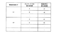
図17は、従来技術のネットワークと無線区間との優先度指標の対応を示す説明図である。 FIG. 17 is an explanatory diagram showing the correspondence of the priority index between the network and the wireless section of the prior art.
図17に示すように、特許文献2のシステムにおいて、基地局200は予め定められたネットワーク1における優先度指標A〜Dと無線区間における優先度指標a〜dとに従って、パケットの無線区間における優先度を決定し、パケットを無線区間における優先度指標に従って、無線区間を介して端末に伝送する。例えば、ネットワーク1における優先度指標がBのパケットは、基地局200によって無線区間における優先度指標にbが付され、端末に伝送される。
本発明が解決しようとする課題は二つある。 There are two problems to be solved by the present invention.
まず、特許文献1に記載された方法は、基地局200にRTP/RTCP又はUDPといったプロトコルを必要とする。これらのプロトコルは、基地局200に本来求められる機能、すなわち、移動体通信網3において伝送されるパケットを無線信号に変換する機能には不要のプロトコルである。従って、RTP/RTCP又はUDP等のプロトコルを追加することは、基地局の実装の複雑さを増大させることとなる。第一の課題は、前述のような基地局の複雑化の回避である。
First, the method described in Patent Document 1 requires the base station 200 to use a protocol such as RTP / RTCP or UDP. These protocols are unnecessary for the function originally required for the base station 200, that is, the function for converting a packet transmitted in the
第二に、図15に示すシステム構成において、例えば、以下の状況が発生する。端末100及び端末101が同じサービスを利用し、端末100はサービスの開始に際してサーバ410への接続を管理サーバ420から指示され、端末101はサービスの開始に際してサーバ411への接続を管理サーバ420から指示される場合があるとする。そして、端末100はゲートウェイ300を介してサーバ410と通信し、端末101はゲートウェイ300を介してサーバ411と通信する。また、サーバ410はゲートウェイ300が存在する場所と物理的に近い位置に存在し、反対に、サーバ411は物理的に遠い位置にある。
Second, in the system configuration shown in FIG. 15, for example, the following situation occurs. The
一般的な通信システムにおいて、物理的に近い距離に存在する装置間の通信は、物理的に遠い距離を隔てて存在する装置間の通信に比べて、達成できる通信品質が良くなると考えられる。例えば通信品質として伝送遅延時間を考えた場合、物理的に近い距離に存在する装置間の通信の伝送遅延時間は小さく、物理的に遠い距離を隔てて存在する装置間の通信の伝送遅延時間は大きい。 In a general communication system, communication between devices that are physically close to each other is considered to improve communication quality that can be achieved compared to communication between devices that are physically separated by a long distance. For example, when the transmission delay time is considered as communication quality, the transmission delay time of communication between devices that are physically close to each other is small, and the transmission delay time of communication between devices that are physically separated by a long distance is large.
前述の場合、図15に示した例において、ゲートウェイ300とサーバ410との間の通信に要する遅延時間は、ゲートウェイ300とサーバ411との間の通信に要する遅延時間より小さいと考えられる。
In the case described above, in the example illustrated in FIG. 15, the delay time required for communication between the gateway 300 and the
しかし、端末100及び端末101は同一のサービスを利用するため、端末100及び端末101とサーバ410及びサーバ411との間の通信に要求される伝送遅延時間は、同等な通信品質でなければならない。なお、各端末と各サーバとの間の通信の伝送遅延時間は、各端末とゲートウェイ300との間の通信の伝送遅延時間と、ゲートウェイ300と各サーバとの間の通信の伝送遅延時間との和である。
However, since the
従って、前述の図15に示した例において、ゲートウェイ300と各サーバとの間の通信の伝送遅延時間に関する前記の関係を考慮すると、端末101とゲートウェイ300との間の通信の伝送遅延時間は、端末100とゲートウェイ300との間の通信の伝送遅延時間より小さい必要がある。
Therefore, in the example illustrated in FIG. 15 described above, in consideration of the relationship regarding the transmission delay time of communication between the gateway 300 and each server, the transmission delay time of communication between the
このように、サーバが分散して配置されたシステムにおいては、端末とサーバ間との通信品質を一定にするために、ゲートウェイ300と各サーバ間との通信品質、すなわちネットワーク2の通信品質に従って、ゲートウェイ300と各端末間との通信品質、すなわちアクセス網1の通信品質が端末毎に個別に制御される必要がある。
Thus, in a system in which servers are arranged in a distributed manner, in order to make the communication quality between the terminal and the server constant, according to the communication quality between the gateway 300 and each server, that is, the communication quality of the
しかし、特許文献2に記載された方法は、図17に示したテーブルを用いることによって、端末毎の個別ではなくサービス毎に優先度が変換されている。従って、第二の課題は、特許文献2によって開示されている方法には、アクセス網の通信品質を端末毎に個別に制御することができないことである。
However, the method described in
本発明の代表的な一例を示せば以下の通りである。すなわち、少なくとも一つの計算機と、第1のネットワークによって前記計算機と接続されるゲートウェイを備える通信システムであって、前記ゲートウェイは、第2のネットワークによって、少なくとも一つの端末と接続され、前記端末は、前記ゲートウェイを介して、前記計算機と通信をし、前記ゲートウェイは、前記端末がサービスの提供を要求するパケットを送信した場合、前記計算機から前記端末へ送信されるパケットを用いることなく、前記端末にサービスを提供する前記計算機に関する評価結果を取得し、前記第1のネットワークにおける前記ゲートウェイから前記計算機までの通信の品質を、前記取得された計算機に関する評価結果に基づいて、推定し、前記推定された通信の品質に従って、前記第2のネットワークにおける前記ゲートウェイと前記端末との通信の優先順位を決定する。 A typical example of the present invention is as follows. That is, a communication system comprising at least one computer and a gateway connected to the computer by a first network, wherein the gateway is connected to at least one terminal by a second network, The gateway communicates with the computer via the gateway, and when the terminal transmits a packet requesting the provision of a service , the gateway sends the packet to the terminal without using a packet transmitted from the computer to the terminal. and acquire the evaluation results relating to the computer which provides the service, the quality of communications from the gateway in said first network to said computer, on the basis of the evaluation results of the obtained computer, estimated were the estimated according to the quality of communication, put to the second network Prioritizing communications between said gateway and said terminal.
本発明の一実施形態によると、基地局の複雑さを増大させることなく、通信品質の制御を、端末毎に制御することができる。 According to an embodiment of the present invention, communication quality can be controlled for each terminal without increasing the complexity of the base station.
(第1の実施形態)
本発明の第1の実施形態を図1のシステム構成図を用いて説明する。
(First embodiment)
A first embodiment of the present invention will be described with reference to the system configuration diagram of FIG.
図1は、本発明の第1の実施形態のシステムを示すブロック図である。 FIG. 1 is a block diagram showing a system according to a first embodiment of the present invention.
第1の実施形態のシステムは、端末100、端末101、アクセス網1、ゲートウェイ302、ネットワーク2、サーバ群430、サーバ410、サーバ411、管理サーバ420、セッション管理サーバ500及びユーザ情報管理サーバ501を備える。
The system of the first embodiment includes a terminal 100, a terminal 101, an access network 1, a
第1の実施形態のシステムと、図15に示す従来技術の分散型のシステムとにおいて、同じ機能及び構成を持つ要素には同じ符号を付している。 In the system of the first embodiment and the distributed system of the prior art shown in FIG. 15, elements having the same function and configuration are denoted by the same reference numerals.
ゲートウェイ302は、アクセス網1とネットワーク2とのインタフェースであり、第1の実施形態におけるゲートウェイである。ゲートウェイ302は、プロセッサ、出力装置、入力装置、ネットワークインタフェース、メモリ及び補助記憶装置を備える計算機である。
The
セッション管理サーバ500は、端末がサーバにセッションを接続する要求を出した際に、サーバを端末に割当てる。セッション管理サーバ500は、例えばSIPサーバを用いてもよい。
ユーザ情報管理サーバ501は、ユーザの情報を保持し、ゲートウェイ302からの要求に従って、端末100又は端末101のユーザの情報を、ゲートウェイ302に送信する。ユーザ情報管理サーバ501は、例えば、3GPPにおけるHSS(Home Subscriber Server)機能を有するサーバでもよい。また、ユーザ情報管理サーバ501に保持されるユーザの情報は、例えば、ユーザが利用可能な帯域幅及びサービス等の、いわゆる加入者情報を含んでもよい。
The user
図1に示すシステムにおいて、端末100がサーバ群430によって提供されるサービスを利用する場合の処理を図2に示す。
In the system shown in FIG. 1, processing when the terminal 100 uses a service provided by the
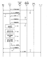
図2は、本発明の第1の実施形態の処理フローを示すシーケンス図である。 FIG. 2 is a sequence diagram illustrating a processing flow according to the first embodiment of this invention.
端末100は、端末100と管理サーバ420との間で、サーバ群430を用いたサービスを開始するためのサービス開始手続き700を実行する。サービス開始手続き700によって端末100に送られる情報には、例えば、端末100によるサービス開始要求、及び管理サーバ420によって指定された端末100が利用するサーバの情報等が含まれる。本実施形態において、サービス開始手続き700の結果、端末100はサーバ410に接続することを、管理サーバ420によって指定される。
The terminal 100 executes a
次に、端末100は、セッション管理サーバ500に、セッション接続要求701を送信する。
Next, the terminal 100 transmits a
セッション管理サーバ500は、セッション接続要求701を受信すると、ゲートウェイ302に、アクセス網1におけるリソースの確保を要求するリソース要求702を送信する。
When the
ゲートウェイ302は、リソース要求702を受信すると、ユーザ情報管理サーバ501に、端末100を使用してサービス開始手続き700を開始したユーザに関する情報を要求する、ユーザ情報要求703を送信する。
When the
ユーザ情報管理サーバ501は、ユーザ情報要求703を受信すると、ユーザ情報管理サーバ501に含まれるユーザ情報の中から、ユーザ情報要求703において要求されたユーザに関する情報を、ユーザ情報回答704として、ゲートウェイ302に送信する。
When the user
ゲートウェイ302は、ユーザ情報回答704を受信すると、ユーザ情報確認ステップ705を実行する。ゲートウェイ302は、ユーザ情報確認ステップ705において、端末100のユーザがリソース要求702にて要求のあったリソースを利用する資格を有するか否かを確認する。
When the
本実施形態において、端末100のユーザが当該リソースを利用する資格が無い場合、ゲートウェイ302は、リソース要求702によって要求のあったリソースを確保できないことを、セッション管理サーバ500に回答する。
In the present embodiment, when the user of the terminal 100 is not qualified to use the resource, the
以下、ユーザ情報確認ステップ705において、端末100がリソース要求702によって要求されたリソースを利用する資格を有する場合について説明する。
Hereinafter, a case where the terminal 100 is qualified to use the resource requested by the
次にゲートウェイ302は、ネットワーク2の通信品質を測定するネットワーク通信品質評価ステップ706を実行する。ネットワーク2の通信品質の測定方法については、後述する。
Next, the
次にゲートウェイ302は、ネットワーク通信品質評価ステップ706で測定されたネットワーク2の通信品質を用いて、優先度指標決定ステップ707を実行し、端末100がセッション接続要求701において接続を要求したセッションによって通信するパケットの、アクセス網1における優先度指標を決定する。優先度指標の決定方法については、後述する。
Next, the
次にゲートウェイ302は、優先度指標決定ステップ707によって決定された優先度指標を用いて、優先度指標書き換え設定ステップ708を実行し、端末100がセッション接続要求701において接続を要求したセッションによって通信するパケットの優先度指標を、書き換える。書き換えられた設定の詳細については、後述する。
Next, the
次にゲートウェイ302は、端末100に割当てることが可能なリソースを、リソース回答709としてセッション管理サーバ500に送信する。
Next, the
セッション管理サーバ500は、リソース回答709を受信すると、端末100に、セッション接続が可能である旨を通知するセッション接続回答710を送信する。
Upon receiving the
端末100は、セッション接続回答710を受信すると、セッション接続要求701において接続を要求されたセッションであり、また、セッション接続回答710において接続可能とされたセッションを用いて、端末100とサーバ410との間で通信し、サービスを実行する(サービス実行711)。
When the terminal 100 receives the
図3は、本発明の第1の実施形態のゲートウェイ302の構成を示すブロック図である。
FIG. 3 is a block diagram illustrating a configuration of the
ゲートウェイ302は、ネットワークインタフェース310、リソース割当て制御部320、ユーザ情報制御部340、ネットワーク通信品質測定部350、優先度指標決定部360、パケット転送部370、及びアクセス網インタフェース330を含む。
The
ネットワークインタフェース310は、ゲートウェイ302とネットワーク2との間のインタフェースである。ネットワークインタフェース310は、ゲートウェイ302とセッション管理サーバ500又はユーザ情報管理サーバ501との間で図2に示した送受信をする際に利用される。また、ネットワークインタフェース310は、端末100と管理サーバ420又はサーバ410とが送受信するパケットをネットワーク2とアクセス網1との間で転送する際に利用される。ネットワークインタフェース310は、例えばイーサネット(登録商標、以下同じ)等の物理インタフェースを備え、TCP/IP等のプロトコルによって通信するインタフェースである。
The
アクセス網インタフェース330は、ゲートウェイ302とアクセス網1との間のインタフェースである。アクセス網インタフェース330は、ゲートウェイ302と端末100又は端末101との通信に利用される。
The
リソース割当て制御部320は、ゲートウェイ302とセッション管理サーバ500との間で定められたプロトコルを実行する。リソース割当て制御部320は、図2において、リソース要求702及びリソース回答709のメッセージを処理する。
The resource
ユーザ情報制御部340は、ゲートウェイ302とユーザ情報管理サーバ501との間で定められたプロトコルを実行する。ユーザ情報制御部340は、図2において、ユーザ情報要求703及びユーザ情報回答704のメッセージ処理、及びユーザ情報確認ステップ705を実行する。
The user
ネットワーク通信品質測定部350は、図2におけるネットワーク通信品質評価ステップ706を実行し、ネットワーク通信品質評価ステップ706によって得られた通信品質の評価結果を優先度指標決定部360に出力する。ネットワークの通信品質の評価方法については、以下に二つの例を示す。
The network communication
図4は、本発明の第1の実施形態のネットワーク通信品質測定方法の一つ目の例を示すフローチャートである。 FIG. 4 is a flowchart illustrating a first example of the network communication quality measurement method according to the first embodiment of this invention.
ネットワーク通信品質測定部350は、サーバ位置推定ステップ351において、端末100の接続先サーバ(図2においてはサーバ410)の情報を用いて、端末100の接続先サーバの位置を推定する。端末100の接続先サーバの情報は、リソース要求702に含まれる。
In the server
ネットワーク2が、例えばIPネットワークである場合、ネットワーク通信品質測定部350は、端末100の接続先サーバのIPアドレスによって、端末100の接続先サーバの物理的な位置を推定してもよい。IPアドレスによって、物理的な位置情報を取得する方法は、ネットワーク通信品質測定部350内に予めIPアドレスと物理的な位置情報を対応させるテーブルを含んでもよいし、また、ネットワーク2経由で提供されるIPアドレスと位置情報のマッピングサービスを利用してもよい。
When the
また、サーバ位置推定ステップ351において、端末100の接続先サーバの位置を推定する方法は、例えば、サーバ群430内のサーバの位置を、あらかじめ管理者によって、ネットワーク2に接続するいずれかのサーバに保存しておき、ゲートウェイ302が取得する方法でもよい。
Further, in the server
次に、ネットワーク通信品質測定部350は、位置−通信品質推定ステップ352において、ステップ351で推定された端末100の接続先サーバの位置情報に基づいて、ゲートウェイ302と端末100の接続先サーバとの間の通信品質を推定する。
Next, in the position-communication
本実施形態における通信品質の推定方法は、例えば図5に示すように、ゲートウェイ302と接続先サーバとの距離に従って通信品質を推定する。
The communication quality estimation method according to the present embodiment estimates the communication quality according to the distance between the
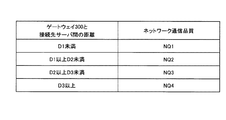
図5は、本発明の第1の実施形態のゲートウェイ302から接続先サーバの距離と通信品質との関係を示す説明図である。
FIG. 5 is an explanatory diagram illustrating a relationship between the distance from the
ネットワーク通信品質測定部350は、距離に関して予め複数の閾値を設定する(図5において、閾値をD1<D2<D3の3種類とする)。ネットワーク通信品質測定部350は、ゲートウェイ302から接続先サーバの距離と上記複数の閾値との間の関係によって、ネットワークの通信品質(図5の例ではNQ1〜NQ4の4種類)を推定する。例えば通信品質として伝送遅延時間を用いた場合、NQ1は、ゲートウェイ302と接続先サーバの間の伝送遅延時間が最も小さい(すなわち通信品質がよい)ことを示し、逆にNQ4は、伝送遅延時間が最も大きい(すなわち通信品質が悪い)ことを示す。
The network communication
図6は、本発明の第1の実施形態のネットワーク通信品質測定方法の二つ目の例を示すフローチャートである。 FIG. 6 is a flowchart illustrating a second example of the network communication quality measurement method according to the first embodiment of this invention.
ネットワーク通信品質測定部350は、端末100の接続先サーバ(図2の例ではサーバ410)に、通信品質を測定することができるコマンドを発行し、通信品質を測定することができるコマンドの結果を取得する。例えば、ネットワーク2がIPネットワークの場合、ゲートウェイ302に備わるネットワーク通信品質測定部350は、接続先サーバにpingコマンドを実行し(通信品質推定コマンド実行ステップ353)、ゲートウェイ302から接続先サーバの間の伝送遅延時間を測定する。
The network communication
次に、ネットワーク通信品質測定部350は、コマンド実行結果−通信品質推定ステップ354において、通信品質推定コマンド実行ステップ353によって得られた結果に基づいて、ゲートウェイ300から接続先サーバの間の通信品質を推定する。
Next , the network communication
図7は、本発明の第1の実施形態のコマンド実行結果と通信品質との関係を示す説明図である。 FIG. 7 is an explanatory diagram illustrating a relationship between the command execution result and the communication quality according to the first embodiment of this invention.
具体的には、通信品質推定コマンド実行ステップ353において使用されたコマンドの結果に対する複数の閾値を、予め設定する(図7において、R1<R2<R3の3種類)。さらに、通信品質測定部350は、通信品質推定コマンド実行ステップ353において発行したコマンドの結果と上記複数の閾値との間の関係によって、通信品質(図7の例においてNQ1〜NQ4の4種類)を推定する。
Specifically, a plurality of threshold values for the command result used in the communication quality estimation
通信品質推定コマンド実行ステップ353においてpingコマンドを発行した場合、R1〜R3は、ゲートウェイ302から接続先サーバまでの伝送遅延時間の閾値を示す。また、NQ1は、ゲートウェイ302から接続先サーバへの伝送遅延時間が最も小さい(すなわち通信品質がよい)ことを示し、逆にNQ4は伝送遅延時間が最も大きい(すなわち通信品質が悪い)ことを示す。
When the ping command is issued in the communication quality estimation
ネットワーク通信品質測定部350は、前述のネットワークの通信品質の測定方法によって得た測定結果を、優先度指標決定部360に出力する。
The network communication
優先度指標決定部360は、ネットワーク通信品質測定部350から入力された通信品質の測定結果に基づいて、セッション接続要求701において接続を要求されたセッションのパケットに付加される、アクセス網1における優先度指標を決定し、パケット転送部370において、決定された優先度指標を設定する。
The priority
図8は、本発明の第1の実施形態のネットワーク2の通信品質推定結果とアクセス網1の優先度指標の関係を示す説明図である。
FIG. 8 is an explanatory diagram illustrating a relationship between the communication quality estimation result of the
優先度指標の決定方法としては、図8に示すテーブルを利用して、ネットワークの通信品質がNQ1の場合はアクセス網1における優先度指標をAP1に決定するような方法を用いる。図8に示されたNQ1〜NQ4は、ネットワーク通信品質測定部350から入力された通信品質の測定結果と同じであり、図5及び図7に示した測定結果と同様に、NQ1が最も通信品質が良く、NQ4が最も通信品質が悪い。
As a method for determining the priority index, a method is used in which the priority index in the access network 1 is determined to be AP1 when the communication quality of the network is NQ1, using the table shown in FIG. NQ1 to NQ4 shown in FIG. 8 are the same as the communication quality measurement results input from the network communication
同一のサービスを実行する場合、端末とサーバとの間の通信品質を一定に保つためには、優先度指標決定部360は、ネットワーク2における通信品質が悪い場合はアクセス網1における優先度を高く、逆にネットワーク2における通信品質がよい場合はアクセス網1における優先度を低くする必要がある。従って、図8の場合、優先度指標決定部360は、アクセス網1における優先度指標であるAP1を最も低く、AP4を最も高くする。
When performing the same service, in order to keep the communication quality between the terminal and the server constant, the priority
次に優先度指標決定部360は、前述の処理によって決定したアクセス網1における優先度指標を、パケット転送部370に設定する。
Next, the priority
図9は、本発明の第1の実施形態の端末識別子とセッション識別子と優先度指標との関係を示す説明図である。 FIG. 9 is an explanatory diagram illustrating a relationship among a terminal identifier, a session identifier, and a priority index according to the first embodiment of this invention.
パケット転送部370は、図9に示すテーブルを含み、端末毎に付された識別子と、当該端末が接続しているセッションの識別子に対応付けて、セッションによって伝送されるパケットのアクセス網1における優先度指標を管理する。優先度指標決定部360は、前述の手順によって決定したアクセス網1における優先度指標を、端末識別子とセッション識別子とに対応付けて、図9のテーブルに設定する。
The
パケット転送部370は、ネットワーク2とアクセス網1との間でやり取りされるパケットを、相互に転送する。また、パケット転送部370は、図9に示す設定に基づいて、パケットのヘッダに含まれる優先度指標を書き換える。例えば、ネットワーク2とアクセス網1との間でやり取りされるパケットがIPパケットであり、ネットワーク2における優先度指標としてIPヘッダ内のTOSフィールドが用いられている場合、パケット転送部370は、図9に示す設定に従って、パケットのTOSフィールドを書き換える。また別な例として、例えばアクセス網1の中において独自のヘッダを用いる場合も、パケット転送部370は、独自のヘッダ内の優先度指標に対応するフィールドを書き換える。
The
また、パケット転送部370は、ネットワーク2又はアクセス網1にパケットを転送する際に、図9に示すアクセス網における優先度指標に従って、パケットを転送してもよい。
Further, when transferring the packet to the
なお、本発明の第1の実施形態のシステムは、サーバ410及びサーバ411を、複数の記憶装置に換え、サーバ群430を記憶装置群としてもよい。
In the system according to the first embodiment of the present invention, the
以上、本発明の第1の実施形態について、端末100、101とサーバ410、411との間の通信を例として説明したが、サーバの代わりにストレージ装置を設け、端末100、101がストレージ装置によって提供される記憶領域にアクセスするための通信についても、前述した第1の実施形態を適用することができる。
The first embodiment of the present invention has been described by taking communication between the
以上、説明したように、本発明の第1の実施形態によると、ゲートウェイ302は、新たなプロトコル、又はゲートウェイ302の機能に不要なプロトコルを追加されることなく、端末とサーバ間との通信品質を一定に保つ制御が可能となる。また、図9に示したように、端末毎及びセッション毎に優先度指標を管理することによって、ゲートウェイ302は、アクセス網1の通信品質を端末毎に個別に制御することが可能となる。
As described above, according to the first embodiment of the present invention, the
(第2の実施形態)
次に、本発明の第2の実施形態について説明する。
(Second Embodiment)
Next, a second embodiment of the present invention will be described.
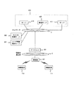
図10は、本発明の第2の実施形態のシステム構成を示すブロック図である。 FIG. 10 is a block diagram illustrating a system configuration according to the second embodiment of this invention.
図10において、図1及び図16と同じ機能及び構成を持つ要素には、同じ符号を付している。ゲートウェイ301及び基地局201は、図16に示すゲートウェイ300及び基地局200と同じ機能を持つ。また、ゲートウェイ301及び基地局201は、以下に示す第2の実施形態の処理も行う。
10, elements having the same functions and configurations as those in FIGS. 1 and 16 are denoted by the same reference numerals. The
まず、第2の実施形態において、移動端末110がサーバ群430によって提供されるサービスを利用する場合の処理について説明する。
First, in the second embodiment, processing when the
図11は、本発明の第2の実施形態の処理フローを示すシーケンス図である。 FIG. 11 is a sequence diagram illustrating a processing flow according to the second embodiment of this invention.
図11において、図2と同じ構成の要素、メッセージ及び動作については同じ符号を付している。第2の実施形態において、サービス開始手続き700から優先度指標決定ステップ707までのフロー、及びリソース回答709からサービス実行711までのフローは、第1の実施形態と同じであるため説明は省略する。
11, elements, messages, and operations having the same configurations as those in FIG. 2 are denoted by the same reference numerals. In the second embodiment, the flow from the
ゲートウェイ301は、基地局201に優先度指標書き換え要求750を送信することによって、優先度指標決定ステップ707において決定された優先度指標を基地局201に送信する。
The
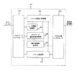
図12は、本発明の第2の実施形態のゲートウェイ301の構成を示すブロック図である。
FIG. 12 is a block diagram illustrating a configuration of the
図12において、図3と同じ構成及び機能を持つ要素には同じ符号を付しており、すなわち、優先度指標決定部361以外の要素には同じ符号を付している。図12において、優先度指標決定部361は、決定した無線区間(基地局201と移動端末110及び移動端末111との間の区間)における優先度指標を、アクセス網インタフェース330及び移動体通信網3を介して、基地局201に送信する。
12, elements having the same configuration and function as those in FIG. 3 are denoted by the same reference numerals, that is, elements other than the priority
基地局201は、優先度指標書き換え設定ステップ758において、優先度指標書き換え要求750によって指定された無線区間における優先度指標を、移動端末110に対する無線区間の優先度に設定する。
In the priority index
図13は、本発明の第2の実施形態の基地局の構成を示すブロック図である。 FIG. 13 is a block diagram illustrating a configuration of a base station according to the second embodiment of this invention.
インタフェース210は、基地局201が移動体通信網3を介してゲートウェイ301等と通信するためのインタフェースである。送受信部220は、基地局と端末との通信に必要な変復調及び誤り訂正符号化/復号等の、いわゆるベースバンド信号処理を行う。無線インタフェース240は、無線信号として送受信される高周波信号と、送受信部220によって処理されるベースバンド信号との間のインタフェースである。アンテナ250は、移動端末110及び移動端末111から送信され、無線インタフェース240によって処理される無線信号を受信し、また、移動端末110及び移動端末111へ、無線インタフェース240によって処理された無線信号を送信する。
The
スケジューリング部230は、各端末のパケットを、優先度指標書き換え要求750で指定された無線区間における優先度指標に基づいて、送受信されるパケットをスケジューリングする。送受信されるパケットをスケジューリングするために、スケジューリング部230が管理する優先度指標のテーブルの例を図14に示す。
The
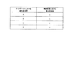
図14は、本発明の第2の実施形態の端末識別子とネットワークにおける優先度指標と無線区間の優先度指標の関係を示す説明図である。 FIG. 14 is an explanatory diagram illustrating a relationship among a terminal identifier, a network priority index, and a wireless section priority index according to the second embodiment of this invention.
無線区間の優先度指標は、移動端末識別子及び移動端末毎のパケットのネットワーク2における優先度指標に対応して管理される。ネットワーク2における優先度指標は、例えばネットワーク2がIPネットワークである場合、IPパケット内に含まれるTOSフィールドの値によって指定されてもよい。優先度指標書き換え設定ステップ758において、スケジューリング部230は、移動端末識別子(図11に示される移動端末110に対応する識別子)とネットワーク2の優先度指標に対応した無線区間の優先度指標を、優先度指標書き換え要求750によって指定された優先度指標に書き換える。
The priority index of the radio section is managed in correspondence with the mobile terminal identifier and the priority index in the
前述の通り、第2の実施形態によると、基地局201とゲートウェイ301とにプロトコルを追加することなく、移動端末とサーバとの間の通信品質を一定に保つ制御が可能となる。また、図14に示したように、端末毎に無線区間の優先度指標を管理することによって、移動体通信網の通信品質を端末毎に個別に制御することが可能となる。
As described above, according to the second embodiment, it is possible to control the communication quality between the mobile terminal and the server to be constant without adding a protocol to the
1 アクセス網
2 ネットワーク
3 移動体通信網
100、101 端末
110、111 移動端末
200、201 基地局
210 インタフェース
220 送受信部
230 スケジューリング部
240 無線インタフェース
250 アンテナ
300、301、302 ゲートウェイ
310 ネットワークインタフェース
320 リソース割当て制御部
330 アクセス網インタフェース
340 ユーザ情報制御部
350 ネットワーク通信品質測定部
360、361 優先度指標決定部
370 パケット転送部
410、411 サーバ
420 管理サーバ
430 サーバ群
500 セッション管理サーバ
501 ユーザ情報管理サーバ
DESCRIPTION OF SYMBOLS 1
Claims (16)
前記ゲートウェイは、第2のネットワークによって、少なくとも一つの端末と接続され、
前記端末は、前記ゲートウェイを介して、前記計算機と通信をし、
前記ゲートウェイは、
前記端末がサービスの提供を要求するパケットを送信した場合、
前記計算機から前記端末へ送信されるパケットを用いることなく、前記端末にサービスを提供する前記計算機に関する評価結果を取得し、
前記第1のネットワークにおける前記ゲートウェイから前記計算機までの通信の品質を、前記取得された計算機に関する評価結果に基づいて、推定し、
前記推定された通信の品質に従って、前記第2のネットワークにおける前記ゲートウェイと前記端末との通信の優先順位を決定することを特徴とする通信システム。 A communication system comprising at least one computer and a gateway connected to the computer by a first network,
The gateway is connected to at least one terminal by a second network;
The terminal communicates with the computer via the gateway,
The gateway is
When the terminal transmits a packet requesting provision of service,
Without using a packet transmitted from the computer to the terminal, obtain an evaluation result regarding the computer that provides a service to the terminal;
Estimating the quality of communication from the gateway to the computer in the first network based on the obtained evaluation result regarding the computer ;
Wherein according to the quality of the estimated communication, communication systems and determines the priority of the communication between the gateway and the terminal in the second network.
前記ゲートウェイは、前記第1のネットワークにおける前記ゲートウェイから前記記憶装置までの通信の品質を推定することを特徴とする請求項1に記載の通信システム。 The computer is a storage device that provides a storage area,
The communication system according to claim 1, wherein the gateway estimates a quality of communication from the gateway to the storage device in the first network.
前記ゲートウェイから前記計算機までの距離の情報を、前記計算機に関する評価結果として、取得し、
前記距離の情報から、前記通信の品質を推定し、
前記通信の品質が低いと推定した場合、前記第2のネットワークにおける前記ゲートウェイと前記端末との通信の優先順位を高く決定することを特徴とする請求項1に記載の通信システム。 The gateway is
Obtain information on the distance from the gateway to the computer as an evaluation result for the computer ,
From the distance information, the communication quality is estimated,
2. The communication system according to claim 1, wherein when the communication quality is estimated to be low, a communication priority between the gateway and the terminal in the second network is determined to be high.
前記計算機のアドレスを、前記計算機に関する評価結果として、取得し、
前記取得された計算機のアドレスと、所定の位置情報とから前記通信の品質を推定し、
前記通信の品質が低いと推定した場合、前記第2のネットワークにおける前記ゲートウェイと前記端末との通信の優先順位を高く決定することを特徴とする請求項1に記載の通信システム。 The gateway is
Obtaining the address of the computer as an evaluation result related to the computer,
Estimating the quality of the communication from the obtained computer address and predetermined position information,
2. The communication system according to claim 1, wherein when the communication quality is estimated to be low, a communication priority between the gateway and the terminal in the second network is determined to be high.
前記計算機に、前記第1のネットワークの通信の品質を推定可能なコマンドを実行することによって、前記計算機に関する評価結果を取得し、
前記コマンドの実行結果が、前記通信の品質が低いことを示す場合、前記第2のネットワークにおける前記ゲートウェイと前記端末との通信の優先順位を高く決定することを特徴とする請求項1に記載の通信システム。 The gateway is
Wherein the computer, by executing an estimation possible commands a quality of communication of the first network, and acquires the evaluation results of the computer,
The priority of communication between the gateway and the terminal in the second network is determined to be high when the execution result of the command indicates that the quality of the communication is low. Communications system.
前記端末との前記通信に用いられるパケットに含まれる優先度を表す領域を、前記決定された優先順位に従って書き換え、
前記書き換えられた優先度を表す領域を含む前記パケットを、前記端末との通信に使用することを特徴とする請求項1に記載の通信システム。 The gateway is
Rewrite the area representing the priority included in the packet used for the communication with the terminal according to the determined priority,
The communication system according to claim 1, wherein the packet including the rewritten priority area is used for communication with the terminal.
前記第2のネットワークは、前記基地局と少なくとも一つの端末と無線ネットワークを備え、
前記基地局は、前記無線ネットワークによって、前記端末と接続され、
前記端末は、前記基地局及び前記ゲートウェイを介して、前記計算機と通信し、
前記ゲートウェイは、前記推定された前記第1のネットワークの通信の品質に従って、前記基地局から前記端末までの前記無線ネットワークにおける前記通信の優先順位を決定することを特徴とする請求項1に記載の通信システム。 The gateway is connected to at least one base station;
The second network comprises the base station, at least one terminal and a wireless network;
The base station is connected to the terminal by the wireless network;
The terminal communicates with the computer via the base station and the gateway,
The gateway, according to the quality of communication of the estimated first network, according to claim 1, characterized in that to determine the priority of the communication in the wireless network to the terminal from the base station Communications system.
前記基地局は、送信された優先順位に従って、前記端末と通信をすることを特徴とする請求項7に記載の通信システム。 The gateway sends the determined communication priority in the wireless network to the base station;
The communication system according to claim 7, wherein the base station communicates with the terminal according to the transmitted priority order.
前記ゲートウェイは、第2のネットワークによって、少なくとも一つの端末と接続され、
前記端末は、前記ゲートウェイを介して、前記計算機と通信をし、
前記ゲートウェイは、
前記端末がサービスの提供を要求するパケットを送信した場合、
前記計算機から前記端末へ送信されるパケットを用いることなく、前記端末にサービスを提供する前記計算機に関する評価結果を取得し、
前記第1のネットワークにおける前記ゲートウェイから前記計算機までの通信の品質を、前記取得された計算機に関する評価結果に基づいて、推定し、
前記推定された通信の品質に従って、前記第2のネットワークにおける前記ゲートウェイと前記端末との通信の優先順位を決定することを特徴とするゲートウェイ。 A gateway connected to at least one computer by a first network,
The gateway is connected to at least one terminal by a second network;
The terminal communicates with the computer via the gateway,
The gateway is
When the terminal transmits a packet requesting provision of service,
Without using a packet transmitted from the computer to the terminal, obtain an evaluation result regarding the computer that provides a service to the terminal;
Estimating the quality of communication from the gateway to the computer in the first network based on the obtained evaluation result regarding the computer ;
The estimated according to the quality of the communication, the gateway characterized by prioritizing communications between the gateway and the terminal in the second network.
前記ゲートウェイは、前記ゲートウェイから前記記憶装置までの、前記第1のネットワークの通信の品質を推定することを特徴とする請求項9に記載のゲートウェイ。 The computer is a storage device that provides a storage area,
The gateway, the gateway of claim 9, wherein the estimating from said gateway to said storage device, the quality of communication of the first network.
前記距離の情報から、前記通信の品質を推定し、
前記通信の品質が低いと推定した場合、前記第2のネットワークにおける前記ゲートウェイと前記端末との通信の優先順位を高く決定することを特徴とする請求項9に記載のゲートウェイ。 Obtain information on the distance from the gateway to the computer as an evaluation result for the computer ,
From the distance information, the communication quality is estimated,
The gateway according to claim 9, wherein when the communication quality is estimated to be low, a priority of communication between the gateway and the terminal in the second network is determined to be high.
前記取得された計算機のアドレスと、所定の位置情報とから前記通信の品質を推定し、
前記通信の品質が低いと推定した場合、前記第2のネットワークにおける前記ゲートウェイと前記端末との通信の優先順位を高く決定することを特徴とする請求項9に記載のゲートウェイ。 Obtaining the address of the computer as an evaluation result related to the computer,
Estimating the quality of the communication from the obtained computer address and predetermined position information,
The gateway according to claim 9, wherein when the communication quality is estimated to be low, a priority of communication between the gateway and the terminal in the second network is determined to be high.
前記コマンドの実行結果が、前記通信の品質が低いことを示す場合、前記第2のネットワークにおける前記ゲートウェイと前記端末との通信の優先順位を高く決定することを特徴とする請求項9に記載のゲートウェイ。 Wherein the computer, by executing an estimation possible commands a quality of communication of the first network, and acquires the evaluation results of the computer,
10. The priority of communication between the gateway and the terminal in the second network is determined to be high when the execution result of the command indicates that the quality of the communication is low. gateway.
前記書き換えられた優先度を表す領域を含む前記パケットを、前記端末との通信に使用することを特徴とする請求項9に記載のゲートウェイ。 Rewrite the area representing the priority included in the packet used for the communication with the terminal according to the determined priority,
The gateway according to claim 9, wherein the packet including an area indicating the rewritten priority is used for communication with the terminal.
前記第2のネットワークは、前記基地局と少なくとも一つの端末と無線ネットワークを備え、
前記基地局は、前記無線ネットワークによって、前記端末と接続され、
前記端末は、前記基地局及び前記ゲートウェイを介して、前記計算機と通信し、
前記ゲートウェイは、前記推定された前記第1のネットワークの通信の品質に従って、前記基地局から前記端末までの前記無線ネットワークにおける前記通信の優先順位を決定することを特徴とする請求項9に記載のゲートウェイ。 The gateway is connected to at least one base station;
The second network comprises the base station, at least one terminal and a wireless network;
The base station is connected to the terminal by the wireless network;
The terminal communicates with the computer via the base station and the gateway,
The gateway, according to the quality of communication of the estimated first network, according to claim 9, characterized in that to determine the priority of the communication in the wireless network to the terminal from the base station gateway.
前記基地局は、送信された優先順位に従って、前記端末と通信をすることを特徴とする請求項15に記載のゲートウェイ。 The gateway sends the determined communication priority in the wireless network to the base station;
The gateway according to claim 15, wherein the base station communicates with the terminal according to the transmitted priority order.
Priority Applications (2)
| Application Number | Priority Date | Filing Date | Title |
|---|---|---|---|
| JP2008327934A JP5123159B2 (en) | 2008-12-24 | 2008-12-24 | Communication system and gateway device |
| US12/633,039 US8451774B2 (en) | 2008-12-24 | 2009-12-08 | Communication system and gateway apparatus |
Applications Claiming Priority (1)
| Application Number | Priority Date | Filing Date | Title |
|---|---|---|---|
| JP2008327934A JP5123159B2 (en) | 2008-12-24 | 2008-12-24 | Communication system and gateway device |
Publications (3)
| Publication Number | Publication Date |
|---|---|
| JP2010154046A JP2010154046A (en) | 2010-07-08 |
| JP2010154046A5 JP2010154046A5 (en) | 2011-06-23 |
| JP5123159B2 true JP5123159B2 (en) | 2013-01-16 |
Family
ID=42265950
Family Applications (1)
| Application Number | Title | Priority Date | Filing Date |
|---|---|---|---|
| JP2008327934A Expired - Fee Related JP5123159B2 (en) | 2008-12-24 | 2008-12-24 | Communication system and gateway device |
Country Status (2)
| Country | Link |
|---|---|
| US (1) | US8451774B2 (en) |
| JP (1) | JP5123159B2 (en) |
Families Citing this family (3)
| Publication number | Priority date | Publication date | Assignee | Title |
|---|---|---|---|---|
| KR101286650B1 (en) * | 2009-12-21 | 2013-07-22 | 한국전자통신연구원 | Apparatus and Method for Alleviation of Inital Connection Delay |
| JP2013016989A (en) * | 2011-07-01 | 2013-01-24 | Nec Corp | Communication system, transmitter, receiver and communication method |
| WO2014056551A1 (en) * | 2012-10-12 | 2014-04-17 | Nokia Siemens Networks Oy | Method and apparatuses for individually control a user equipment in order optimise the quality of experience (qoe) |
Family Cites Families (10)
| Publication number | Priority date | Publication date | Assignee | Title |
|---|---|---|---|---|
| JP2003087300A (en) * | 2001-09-11 | 2003-03-20 | Matsushita Electric Ind Co Ltd | Device and method for transmitting packet and communication system |
| JP3639556B2 (en) * | 2001-12-12 | 2005-04-20 | 富士通株式会社 | VoIP network congestion control system |
| US7552077B1 (en) * | 2002-06-26 | 2009-06-23 | Trading Technologies International, Inc. | System and method for coalescing market data at a network device |
| US20040122976A1 (en) * | 2002-10-24 | 2004-06-24 | Ashutosh Dutta | Integrated mobility management |
| JP2004186843A (en) * | 2002-12-02 | 2004-07-02 | Nec Engineering Ltd | Voice gateway apparatus |
| JP4293866B2 (en) * | 2003-09-03 | 2009-07-08 | 富士通株式会社 | Network management system |
| EP1667351A4 (en) * | 2003-09-10 | 2012-10-17 | Fujitsu Ltd | Transmission parameter control device |
| JP4451824B2 (en) | 2005-08-17 | 2010-04-14 | 日本電信電話株式会社 | Wireless base station |
| JP2008072655A (en) * | 2006-09-15 | 2008-03-27 | Fujitsu Ltd | Service communication control method, service relaying apparatus and service communication control system |
| CN101971578B (en) * | 2007-12-28 | 2014-07-30 | 茨特里克斯系统公司 | Tcp packet spacing |
-
2008
- 2008-12-24 JP JP2008327934A patent/JP5123159B2/en not_active Expired - Fee Related
-
2009
- 2009-12-08 US US12/633,039 patent/US8451774B2/en not_active Expired - Fee Related
Also Published As
| Publication number | Publication date |
|---|---|
| US20100157898A1 (en) | 2010-06-24 |
| US8451774B2 (en) | 2013-05-28 |
| JP2010154046A (en) | 2010-07-08 |
Similar Documents
| Publication | Publication Date | Title |
|---|---|---|
| JP7071015B2 (en) | Methods, network elements, and systems for determining network quality of service flow | |
| KR100823737B1 (en) | Bridge for Heterogeneous QoS Networks | |
| KR100776308B1 (en) | method and apparatus for scheduling to guarantee QoS of VoIP service in portable internet system | |
| US20110113146A1 (en) | Dynamic quality of service (qos) setup over wired and wireless networks | |
| KR100809261B1 (en) | High speed plc network-ethernet bridge system supporting qos | |
| WO2015037684A1 (en) | Application state change notification program and method therefor | |
| JP2020511083A (en) | Service quality control method and device, SMF, UPF, UE, PCF and AN | |
| KR20090121327A (en) | Parameterized quality of service in a network | |
| TW201611556A (en) | Scalable policy-controlled packet inspection systems and methods for advanced application interface | |
| JP2005537764A (en) | Mechanism for providing QoS in a network using priority and reserve bandwidth protocols | |
| JP6063998B2 (en) | Telecommunication system and telecommunication method | |
| US9071984B1 (en) | Modifying a data flow mechanism variable in a communication network | |
| US20210329528A1 (en) | Connection establishment method and related device | |
| CN102549981B (en) | The node controlled for service quality (QoS) and method | |
| WO2021139696A1 (en) | Method, apparatus and system for sending report information | |
| WO2011144152A1 (en) | Method for providing information, home gateway and home network system | |
| US20120102162A1 (en) | Dynamic bandwidth adjustment for multiple service support | |
| JPWO2010125761A1 (en) | COMMUNICATION BAND CONTROL DEVICE AND COMMUNICATION BAND CONTROL METHOD | |
| JP5123159B2 (en) | Communication system and gateway device | |
| GB2386282A (en) | Allocating shared resources in a packet data communications network | |
| US10021589B2 (en) | Wireless data system that associates internet protocol ports with quality-of-service for user applications | |
| JP4931969B2 (en) | Network quality measurement system and method and program | |
| WO2018177003A1 (en) | Charging method, and related device and system | |
| KR101925912B1 (en) | Packet Processing Method and Apparatus | |
| KR101777812B1 (en) | Network data processing speed measuring method and apparatus |
Legal Events
| Date | Code | Title | Description |
|---|---|---|---|
| A521 | Request for written amendment filed |
Free format text: JAPANESE INTERMEDIATE CODE: A523 Effective date: 20110509 |
|
| A621 | Written request for application examination |
Free format text: JAPANESE INTERMEDIATE CODE: A621 Effective date: 20110509 |
|
| A521 | Request for written amendment filed |
Free format text: JAPANESE INTERMEDIATE CODE: A523 Effective date: 20120309 |
|
| A131 | Notification of reasons for refusal |
Free format text: JAPANESE INTERMEDIATE CODE: A131 Effective date: 20120612 |
|
| A977 | Report on retrieval |
Free format text: JAPANESE INTERMEDIATE CODE: A971007 Effective date: 20120613 |
|
| A521 | Request for written amendment filed |
Free format text: JAPANESE INTERMEDIATE CODE: A523 Effective date: 20120810 |
|
| TRDD | Decision of grant or rejection written | ||
| A01 | Written decision to grant a patent or to grant a registration (utility model) |
Free format text: JAPANESE INTERMEDIATE CODE: A01 Effective date: 20121016 |
|
| A01 | Written decision to grant a patent or to grant a registration (utility model) |
Free format text: JAPANESE INTERMEDIATE CODE: A01 |
|
| A61 | First payment of annual fees (during grant procedure) |
Free format text: JAPANESE INTERMEDIATE CODE: A61 Effective date: 20121025 |
|
| FPAY | Renewal fee payment (event date is renewal date of database) |
Free format text: PAYMENT UNTIL: 20151102 Year of fee payment: 3 |
|
| R150 | Certificate of patent or registration of utility model |
Free format text: JAPANESE INTERMEDIATE CODE: R150 |
|
| LAPS | Cancellation because of no payment of annual fees |