JP5120987B2 - Apparatus, method and system for image processing - Google Patents
Apparatus, method and system for image processing Download PDFInfo
- Publication number
- JP5120987B2 JP5120987B2 JP2011502964A JP2011502964A JP5120987B2 JP 5120987 B2 JP5120987 B2 JP 5120987B2 JP 2011502964 A JP2011502964 A JP 2011502964A JP 2011502964 A JP2011502964 A JP 2011502964A JP 5120987 B2 JP5120987 B2 JP 5120987B2
- Authority
- JP
- Japan
- Prior art keywords
- pixel data
- buffer
- alpha
- foreground
- data
- Prior art date
- Legal status (The legal status is an assumption and is not a legal conclusion. Google has not performed a legal analysis and makes no representation as to the accuracy of the status listed.)
- Expired - Fee Related
Links
Images


Classifications
-
- G—PHYSICS
- G06—COMPUTING; CALCULATING OR COUNTING
- G06T—IMAGE DATA PROCESSING OR GENERATION, IN GENERAL
- G06T15/00—3D [Three Dimensional] image rendering
- G06T15/50—Lighting effects
- G06T15/60—Shadow generation
-
- G—PHYSICS
- G06—COMPUTING; CALCULATING OR COUNTING
- G06T—IMAGE DATA PROCESSING OR GENERATION, IN GENERAL
- G06T15/00—3D [Three Dimensional] image rendering
- G06T15/50—Lighting effects
- G06T15/503—Blending, e.g. for anti-aliasing
Landscapes
- Engineering & Computer Science (AREA)
- Computer Graphics (AREA)
- Physics & Mathematics (AREA)
- General Physics & Mathematics (AREA)
- Theoretical Computer Science (AREA)
- Image Generation (AREA)
- Image Processing (AREA)
- Controls And Circuits For Display Device (AREA)
Description
本発明は画像処理に関し、特にコンピュータグラフィックス(CG:Computer Graphics)の描画処理に関する。 The present invention relates to image processing, and more particularly, to computer graphics (CG) drawing processing.
CG処理の一つに、物体の影を生成する手法、すなわち影生成手法がある。影生成手法は、3次元CGだけでなく、ウィンドウシステム等の2次元CGにも利用される。 One of the CG processes is a method of generating an object shadow, that is, a shadow generation method. The shadow generation method is used not only for three-dimensional CG but also for two-dimensional CG such as a window system.
従来の影生成手法は一般に次の手順で行われる。まず、背景のデータがフレームバッファに書き込まれる。次に、前景の影のデータが、フレームバッファとは別の一時バッファを利用して計算され、その一時バッファに記憶される。ここで、影のデータの計算に一時バッファが利用されることにより、フレームバッファに書き込まれた背景のデータにかかわらず、複数の異なる影を同じピクセルに重ね書きしてそのピクセルでの影の色を過度に濃くすること、すなわち影の重複描画を容易に防止することができる。続いて、一時バッファの画像データがフレームバッファの画像データにアルファ合成されてフレームバッファに書き込まれる。最後に、前景のデータがフレームバッファに書き込まれる。 The conventional shadow generation method is generally performed in the following procedure. First, background data is written into the frame buffer. Next, foreground shadow data is calculated using a temporary buffer different from the frame buffer and stored in the temporary buffer. Here, a temporary buffer is used to calculate shadow data, so that multiple different shadows can be overwritten on the same pixel regardless of the background data written to the frame buffer, and the shadow color at that pixel. Can be prevented from being excessively dark, that is, overlapping drawing of shadows can be easily prevented. Subsequently, the image data in the temporary buffer is alpha-synthesized with the image data in the frame buffer and written into the frame buffer. Finally, foreground data is written to the frame buffer.
近年、CGに対する更なる高機能化や高画質化への要求を満たすべく、画像処理の更なる高速化が求められている。しかし、従来の影生成手法では、上記のとおり、フレームバッファとは別の一時バッファが必要である。例えばHDTV(High Definition TeleVision:高精細テレビ)の画像処理では一時バッファとして4MBのメモリ容量が必要である。従って、従来の影生成手法では、画像処理に割り当てられるメモリの容量および帯域の更なる削減が困難である。その結果、画像処理の更なる高速化が困難である。 In recent years, there has been a demand for further speeding up of image processing in order to satisfy the demand for higher functionality and higher image quality for CG. However, the conventional shadow generation method requires a temporary buffer different from the frame buffer as described above. For example, in HDTV (High Definition TeleVision: high-definition television) image processing, a memory capacity of 4 MB is required as a temporary buffer. Therefore, with the conventional shadow generation method, it is difficult to further reduce the capacity and bandwidth of the memory allocated for image processing. As a result, it is difficult to further speed up image processing.
本発明の目的は、上記の問題を解決した、新規でかつ有用な画像処理装置、画像処理方法、および画像処理システムを提供することにある。本発明の具体的な目的は、一時バッファを利用することなく、影が合成可能な画像処理装置、画像処理方法、および、画像処理システムを提供することにある。 An object of the present invention is to provide a novel and useful image processing apparatus, an image processing method, and an image processing system that solve the above problems. A specific object of the present invention is to provide an image processing apparatus, an image processing method, and an image processing system capable of combining shadows without using a temporary buffer.
本発明の一態様によれば、画像の前景および背景のデータを記憶するメモリと、バッファと、前記メモリおよび前記バッファに接続されたプロセッサと、を備え、前記プロセッサが、前記メモリから前記前景のデータを読み出して前景の影のデータを生成し、該影のデータを前記バッファに書き込み、前記影のデータを前記バッファから読み出して、前記背景のデータとアルファ合成し、アルファ合成されたデータを前記バッファに書き込み、前記アルファ合成されたデータが書き込まれた前記バッファに、前記前景のデータを書き込む、ように構成されてなる、装置が提供される。 According to one aspect of the present invention, a memory for storing foreground and background data of an image, a buffer, and a processor connected to the memory and the buffer are provided, the processor from the memory Read data to generate foreground shadow data, write the shadow data to the buffer, read the shadow data from the buffer, alpha-synthesize the background data, and alpha-synthesized data An apparatus is provided that is configured to write the foreground data to the buffer that has been written to the buffer and the alpha combined data has been written.
本発明によれば、プロセッサが、背景のデータよりも先に前景の影のデータを、最終的に画像が形成されることになるバッファに書き込む。さらに、プロセッサが、そのバッファに既に書き込まれている前景の影のデータに背景のデータをアルファ合成する。さらに、アルファ合成されたデータが書き込まれたそのバッファに、前景のデータを書き込む。これにより、前景とその影と背景とが合成された画像がそのバッファに形成される。したがって、そのバッファとは別の一時バッファを利用することなく、前景の影の画像を処理できる。 In accordance with the present invention, the processor writes the foreground shadow data into the buffer where the image will eventually be formed prior to the background data. Further, the processor alpha-combines the background data with the foreground shadow data already written in the buffer. Further, the foreground data is written into the buffer in which the alpha synthesized data is written. As a result, an image in which the foreground, its shadow and background are combined is formed in the buffer. Therefore, a foreground shadow image can be processed without using a temporary buffer different from the buffer.
本発明の他の態様によれば、画像の前景および背景のデータを記憶するメモリと、バッファと、前記メモリから前記前景のデータを読み出して前景の影のデータを生成し、該影のデータを前記バッファに書き込む影描画手段と、前記影のデータを前記バッファから読み出して、前記背景のデータとアルファ合成し、アルファ合成されたデータを前記バッファに書き込む背景合成手段と、前記アルファ合成されたデータが書き込まれた前記バッファに、前記前景のデータを書き込む前景合成手段と、を備える、装置が提供される。 According to another aspect of the present invention, a memory for storing foreground and background data of an image, a buffer, and reading the foreground data from the memory to generate foreground shadow data, Shadow drawing means for writing into the buffer, background data for reading out the shadow data from the buffer, alpha synthesis with the background data, and writing the alpha synthesized data into the buffer, and the alpha synthesized data Foreground composition means for writing the foreground data into the buffer in which is written.
本発明によれば、背景のデータがバッファに書き込まれるよりも先に、影描画手段が前景の影のデータを生成して、最終的に画像が形成されることになるバッファに書き込む。さらに、背景合成手段が、バッファに既に書き込まれている前景の影のデータに背景のデータをアルファ合成する。さらに、前景合成手段が、アルファ合成されたデータが書き込まれたバッファに、前景のデータを書き込む。これにより、前景とその影と背景とが合成された画像がそのバッファに形成される。したがって、そのバッファとは別の一時バッファを利用することなく、前景の影の画像を処理できる。 According to the present invention, before the background data is written into the buffer, the shadow drawing unit generates the foreground shadow data and writes it into the buffer where an image is finally formed. Further, the background synthesis means alpha-synthesizes the background data with the foreground shadow data already written in the buffer. Further, the foreground synthesis means writes the foreground data into the buffer in which the alpha synthesized data is written. As a result, an image in which the foreground, its shadow and background are combined is formed in the buffer. Therefore, a foreground shadow image can be processed without using a temporary buffer different from the buffer.
本発明のその他の態様によれば、前景のデータから前景の影のデータを生成してバッファに書き込むステップと、前記影のデータを前記バッファから読み出して、前記背景のデータとアルファ合成し、アルファ合成されたデータを前記バッファに書き込むステップと、前記アルファ合成されたデータが書き込まれた前記バッファに、前記前景のデータを書き込むステップと、を含む、方法が提供される。 According to another aspect of the present invention, generating foreground shadow data from foreground data and writing it to a buffer; reading the shadow data from the buffer; and alpha-combining with the background data; A method is provided comprising: writing synthesized data into the buffer; and writing the foreground data into the buffer into which the alpha synthesized data has been written.
本発明によれば、背景のデータよりも先に前景の影のデータがバッファに書き込まれ、バッファに既に書き込まれている前景の影のデータに背景のデータがアルファ合成される。さらに、アルファ合成されたデータが書き込まれたそのバッファに、前景のデータが書き込まれる。これにより、前景とその影と背景とが合成された画像がそのバッファに形成される。したがって、そのバッファとは別の一時バッファを利用することなく、前景の影の画像を処理できる。 According to the present invention, the foreground shadow data is written in the buffer before the background data, and the background data is alpha-combined with the foreground shadow data already written in the buffer. Further, the foreground data is written into the buffer in which the alpha synthesized data is written. As a result, an image in which the foreground, its shadow and background are combined is formed in the buffer. Therefore, a foreground shadow image can be processed without using a temporary buffer different from the buffer.
本発明のその他の態様によれば、画像の前景および背景のデータを記憶するメモリと、バッファと、前記メモリおよび前記バッファに接続されたプロセッサと、を備えた装置の前記プロセッサに、前景のデータから前景の影のデータを生成してバッファに書き込むステップと、前記影のデータを前記バッファから読み出して、前記背景のデータとアルファ合成し、アルファ合成されたデータを前記バッファに書き込むステップと、前記アルファ合成されたデータが書き込まれた前記バッファに、前記前景のデータを書き込むステップと、を実行させるためのプログラムが提供される。 According to another aspect of the invention, foreground data is provided to the processor of an apparatus comprising a memory for storing foreground and background data of an image, a buffer, and a processor connected to the memory and the buffer. Generating foreground shadow data from the buffer and writing it to a buffer; reading the shadow data from the buffer; alpha-synthesizing with the background data; and writing alpha-synthesized data into the buffer; A program for executing the step of writing the foreground data to the buffer in which the alpha synthesized data is written.
本発明によれば、上記の効果と同様の効果が得られる。 According to the present invention, the same effect as described above can be obtained.
本発明のその他の態様によれば、システムであって、画像の前景および背景のデータを記憶するメモリと、バッファと、前記メモリおよび前記バッファに接続された第1のプロセッサと、当該画像処理システムの制御を行う第2のプロセッサと、を備え、前記第1のプロセッサが、前記メモリから前記前景のデータを読み出して前景の影のデータを生成し、該影のデータを前記バッファに書き込み、前記影のデータを前記バッファから読み出して、前記背景のデータとアルファ合成し、アルファ合成されたデータを前記バッファに書き込み、前記アルファ合成されたデータが書き込まれた前記バッファに、前記前景のデータを書き込む、ように構成されてなる、前記システムが提供される。 According to another aspect of the present invention, there is provided a system, a memory for storing foreground and background data of an image, a buffer, a first processor connected to the memory and the buffer, and the image processing system. A second processor that controls the foreground, wherein the first processor reads the foreground data from the memory to generate foreground shadow data, writes the shadow data to the buffer, and The shadow data is read from the buffer, alpha-combined with the background data, the alpha-synthesized data is written to the buffer, and the foreground data is written to the buffer where the alpha-synthesized data is written. The system is configured as follows.
本発明によれば、上記の効果と同様の効果が得られる。 According to the present invention, the same effect as described above can be obtained.
本発明のその他の態様によれば、システムであって、画像の前景および背景のデータを記憶するメモリと、バッファと、当該画像処理システムの制御を行うプロセッサと、前記メモリから前記前景のデータを読み出して前景の影のデータを生成し、該影のデータを前記バッファに書き込む影描画手段と、前記影のデータを前記バッファから読み出して、前記背景のデータとアルファ合成し、アルファ合成されたデータを前記バッファに書き込む背景合成手段と、前記アルファ合成されたデータが書き込まれた前記バッファに、前記前景のデータを書き込む前景合成手段と、を備える、前記システムが提供される。 According to another aspect of the present invention, there is provided a system, a memory for storing foreground and background data of an image, a buffer, a processor for controlling the image processing system, and the foreground data from the memory. Data that is read to generate foreground shadow data, writes the shadow data to the buffer, and the shadow data is read from the buffer and alpha-synthesized with the background data. The system is provided with: background composition means for writing data into the buffer; and foreground composition means for writing the foreground data into the buffer into which the alpha-combined data has been written.
本発明によれば、上記の効果と同様の効果が得られる。 According to the present invention, the same effect as described above can be obtained.
本発明によれば、一時バッファを利用することなく、影が合成可能な画像処理のための装置、方法、およびシステムが提供できる。 According to the present invention, it is possible to provide an apparatus, a method, and a system for image processing capable of combining shadows without using a temporary buffer.
以下、本発明の好ましい実施形態について、図面を参照しながら説明する。 Hereinafter, preferred embodiments of the present invention will be described with reference to the drawings.
《第1の実施形態》
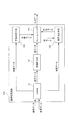
図1は、本発明の第1の実施形態に係る画像処理システム100のブロック図である。図1を参照するに、この画像処理システム100はパーソナルコンピュータ等のコンピュータ端末を用いて実現され、そのコンピュータ端末に接続されたモニタ30、例えば、アナログモニタ30A、デジタルモニタ30B、および/またはTV受像器30CにCG画像を表示する。アナログモニタ30Aは液晶ディスプレイ(LCD)またはブラウン管モニタ(CRT)である。デジタルモニタ30BはLCDまたはデジタルプロジェクタである。TV受像器30Cはビデオテープレコーダ(VTR)に置き換えられてもよい。
<< First Embodiment >>
FIG. 1 is a block diagram of an
画像処理システム100は、グラフィックスボード10、マザーボード20、およびシステムバス60を含む。グラフィックスボード10は、画像処理装置10A、内部バス13、入出力インタフェース(I/O)14、表示用データ生成器15、およびAV端子16を含む。マザーボード20は、CPU21、メインメモリ22、およびI/O23を含む。なお、グラフィックスボード10はマザーボード20に統合されていてもよい。システムバス60は、グラフィックスボード10とマザーボード20との間を接続するバスである。システムバス60はPCI−Express規格に準拠している。その他に、システムバス60はPCI規格またはAGP規格に準拠していてもよい。
The
画像処理装置10Aはグラフィックス処理専用のプロセッサ(GPU:Graphics Processing Unit)11とビデオメモリ(VRAM)12とを含む。GPU11とVRAM12とは内部バス13によって接続されている。
The
GPU11は、グラフィックス表示に必要な演算処理に特化した、チップ等の論理回路である。GPU11の行うCG処理にはジオメトリ処理とレンダリング処理とがある。ジオメトリ処理では、幾何学的演算、特に座標変換により、3次元仮想空間の中に想定された各モデルを2次元画面に投影したときの配置が決定される。レンダリング処理では、ジオメトリ処理で決定された2次元画面上での各モデルの配置に基づき、2次元画面に実際に表示されるべき画像のデータが生成される。レンダリング処理には、隠面消去、シェーディング、シャドウイング、テクチャマッピング等が含まれる。
The
GPU11は、頂点シェーダ11A、ピクセルシェーダ11B、およびROP(Rendering Output Pipeline、または、Rasterizing OPeration)ユニット11Cを含む。
The
頂点シェーダ11Aはジオメトリ処理専用の演算器であり、ジオメトリ処理に必要な幾何学的演算、特に座標変換に関する演算に利用される。頂点シェーダ11Aは、幾何学的演算の種類別に用意された演算器であっても、プログラムによって種々の幾何学的演算を処理可能な演算器であってもよい。
The
ピクセルシェーダ11Bはレンダリング処理専用の演算器であり、レンダリング処理に必要な各ピクセルの色情報、すなわちピクセルデータの処理に関する演算に利用される。ピクセルシェーダ11Bは、VRAM12から画像データをピクセル単位で読み出して、その成分間の和および積をピクセル単位で計算できる。ピクセルシェーダ11Bは、ピクセルデータの処理に関する演算の種類別に用意された演算器であっても、プログラムによって種々の演算をピクセル単位で処理可能な演算器であってもよい。さらに、同じプログラム可能な演算器がプログラムに応じて、頂点シェーダ11Aおよびピクセルシェーダ11Bとして使い分けられてもよい。
The
なお、ピクセルデータは例えばARGB4:4:4:4で表現される。RGBは三原色の各成分を表し、Aはアルファ値を表す。ここで、アルファ値は、同じピクセルデータの色成分を他のピクセルデータの色成分とアルファ合成するときの重みを表す。アルファ値は、正規化された場合0〜1の間の数値をとり、百分率で表した場合0〜100%の数値をとる。アルファ値は、アルファ合成における各ピクセルデータの色成分の不透明の度合いを意味する場合もある。 Note that the pixel data is expressed in, for example, ARGB 4: 4: 4: 4. RGB represents each component of the three primary colors, and A represents an alpha value. Here, the alpha value represents a weight when the color component of the same pixel data is alpha combined with the color component of the other pixel data. The alpha value takes a numerical value between 0 and 1 when normalized, and takes a numerical value between 0 and 100% when expressed as a percentage. The alpha value may mean the degree of opacity of the color component of each pixel data in alpha composition.
ROPユニット11Cは、レンダリング処理専用の演算器であり、レンダリング処理において、ピクセルシェーダ11Bによって生成されたピクセルデータをVRAM12に書き込む。ROPユニット11Cはさらに、そのピクセルデータの各成分と、VRAM12に記憶された別のピクセルデータの各成分との和および積を計算できる。その機能を利用することで、ROPユニット11Cは特に、フレームバッファ12Aの画像データにVRAM12の別領域の画像データをアルファ合成して、フレームバッファ12Aに書き込むことができる。
The
VRAM12は、例えば、シンクロナスDRAM(SDRAM)であり、好ましくは、DDR(Double−Data−Rate)−SDRAM、またはGDDR(Graphic−DDR)−SDRAMである。VRAM12はフレームバッファ12Aを含む。フレームバッファ12Aは、GPU11によって処理された、モニタ30に出力されるべき1フレームの画像データを記憶する。フレームバッファ12Aの各メモリセルが一つのピクセルの色情報、すなわち一組のピクセルデータを記憶する。ここで、ピクセルデータは例えばARGB4:4:4:4で表現される。VRAM12は、フレームバッファ12Aの他に、各種テクスチャ等の画像データの記憶領域やGPU11用の演算バッファ領域を含む。
The
I/O14は、内部バス13をシステムバス60に接続するインタフェースであり、システムバス60を通してグラフィックスボード10とマザーボード20との間でデータを交換する。I/O14はPCI−Express規格に準拠している。その他に、I/O14はPCI規格またはAGP規格に準拠していてもよい。なお、I/O14は、GPU11と同じチップに組み込まれていてもよい。
The I /
表示用データ生成器15は、フレームバッファ12Aからピクセルデータを読み出して表示用データとして出力するためのチップ等のハードウェアである。表示用データ生成器15は、フレームバッファ12Aのアドレス範囲をモニタ30の画面に対応させ、そのアドレス範囲の中に読み出しアドレスを生成するごとに、その読み出しアドレスからピクセルデータを順番に読み出して一連の表示用データとして出力する。なお、表示用データ生成器15は、GPU11と同じチップに組み込まれていてもよい。
The
AV端子16は、モニタ30に接続され、表示用データ生成器15から出力された表示用データを、モニタ30への出力に適した信号形式に変換してモニタ30に出力する。AV端子16は例えば、アナログRGBコネクタ16A、DVIコネクタ16B、およびS端子16Cを含む。アナログRGBコネクタ16Aは、表示用データをアナログRGB信号に変換してアナログモニタ30Aに出力する。DVIコネクタ16Bは、表示用データをDVI信号に変換してデジタルモニタ30Bに出力する。S端子16Cは、表示用データを、NTSC、PAL、またはHDTVのTV信号に変換してTV受像器30Cに出力する。ここで、TV信号は、S信号、コンポジット信号、またはコンポーネント信号のいずれでもよい。AV端子16はその他に、HDMIコネクタやD端子等、他の種類のコネクタや端子を含んでもよい。なお、表示用データを適切な信号形式に変換する機能は、AV端子16の代わりにGPU11に実装されていてもよい。その場合、GPU11は表示用データを、出力先のモニタ30の種類に応じた信号形式に変換して、AV端子16からモニタ30に出力する。
The
CPU21は、メインメモリ22に記憶されているプログラムを実行し、そのプログラムに従って、グラフィックスボード10に処理対象の画像データを与え、グラフィックスボード10の各要素の動作を制御する。CPU21はメインメモリ22からVRAM12に画像データを書き込むことができる。そのとき、CPU21は画像データの形式を、GPU11によって処理可能な形式、例えばARGB4:4:4:4に変換してもよい。
The
メインメモリ22は、CPU21によって実行されるプログラム、および、グラフィックスボード10による処理対象の画像データを記憶する。
The
I/O23は、CPU21およびメインメモリ22をシステムバス60に接続するインタフェースであり、システムバス60を通してグラフィックスボード10とマザーボード20との間でデータを交換する。I/O23はPCI−Express規格に準拠している。その他に、I/O23はPCI規格またはAGP規格に準拠していてもよい。
The I /
図2は、画像処理装置10Aの機能構成を示すブロック図である。図2を参照するに、画像処理装置10Aは、影描画手段101、背景合成手段102、および前景合成手段103を含む。これら三つの手段101、102、103はGPU11によって実現され、前景の影を生成して背景に描画する処理を行う。ここで、前景のデータおよび背景のデータは予め、例えばCPU21の命令によってVRAM12に記憶されている。なお、CPU21の代わりにGPU11の命令によってVRAM12に記憶されていてもよい。また、VRAM12の代わりに、CPU21あるいはGPU11がアクセス可能なメモリ、例えば、メインメモリ22に前景のデータおよび背景のデータが記憶されていてもよい。
FIG. 2 is a block diagram illustrating a functional configuration of the
影描画手段101は、CPU21からの指示に従い、VRAM12に記憶された前景のデータからその前景の影のデータを生成して、フレームバッファ12Aに書き込む。
The
図3Aは、影描画手段101による前景FGの影SHのデータの生成およびフレームバッファ12Aへの書き込みの説明図である。図3Aを参照するに、影描画手段101はまず、影SHの色とアルファ値0%とを示すピクセルデータでフレームバッファ12Aの全体を埋める。影描画手段101は次に、VRAM12に記憶された前景FGのデータからその前景FGの影SHのアルファ値を生成してフレームバッファ12Aに書き込む。ここで、影描画手段101は頂点シェーダ11Aを利用して影SHの形を計算してもよい。
FIG. 3A is an explanatory diagram of generation of shadow SH data of the foreground FG and writing to the
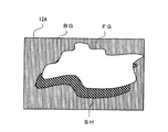
図3Bは、影描画手段101によってフレームバッファ12Aに書き込まれた前景FGの影SHのデータを模式的に表す図である。図3Bを参照するに、斜線部は影SHの範囲を示す。その範囲の内側ではアルファ値が0%より大きいので影の色が表示され、その範囲の外側ではアルファ値が0%であるので影の色が表示されない。このように、フレームバッファ12Aには影SHのデータが記憶される。
FIG. 3B is a diagram schematically showing the shadow SH data of the foreground FG written to the
なお、前景が一つで、光源が複数の場合や、前景が複数で光源が一つの場合、あるいはこれらの組み合わせの場合は、複数の異なる影が生じる。このような場合、影描画手段101は、それらの影のデータを一つずつ順番に生成してフレームバッファ12Aに書き込む。新たに生成された影が、フレームバッファ12Aに先に書き込まれた影と同じピクセルで重なる場合、影描画手段101は、新たに生成された影と先に書き込まれた影とでそのピクセルのアルファ値を比較して、いずれか大きい方をそのピクセルのアルファ値として選択する。こうして、影の重複描画が容易に防止される。
In addition, when there is one foreground and a plurality of light sources, when there are a plurality of foregrounds and one light source, or a combination thereof, a plurality of different shadows are generated. In such a case, the
図2に戻り、背景合成手段102は、VRAM12に記憶された背景のデータをフレームバッファ12Aの画像データにアルファ合成してフレームバッファ12Aに書き込む。
Returning to FIG. 2, the background synthesis means 102 alpha-synthesizes the background data stored in the
図4Aは、背景合成手段102による前景の影SHのデータと背景BGのデータとのアルファ合成の説明図である。図4Aを参照するに、背景合成手段102は、VRAM12から背景BGのピクセルデータを読み出して、背景BGの各ピクセルデータをフレームバッファ12Aの対応するピクセルデータにアルファ合成し、アルファ合成されたピクセルデータでフレームバッファ12Aの元のピクセルデータを更新する。背景合成手段102はそれらの操作をフレームバッファ12Aの全てのピクセルデータについて繰り返すことにより、アルファ合成された前景の影SHと背景BGとのデータをフレームバッファ12Aに書き込むことができる。
FIG. 4A is an explanatory diagram of alpha composition of foreground shadow SH data and background BG data by the
図4Bは、背景合成手段102によってフレームバッファ12Aに書き込まれた、アルファ合成された前景の影SHと背景BGとのデータを模式的に表す図である。図4Bを参照するに、斜線部は影SHの範囲を示し、横線部は背景BGの範囲を示す。影SHの内側では影SHの色と背景BGの色とが、それぞれのアルファ値に応じた割合で加算されて表示される。一方、影SHの外側では影SHのアルファ値が0%であるので、背景BGの色が背景BGのアルファ値の重みで表示される。
FIG. 4B is a diagram schematically illustrating the data of the foreground shadow SH and background BG, which are alpha-combined, written to the
図2に戻り、前景合成手段103は、VRAM12に記憶された前景のデータをフレームバッファ12Aに書き込む。
Returning to FIG. 2, the
図5Aは、前景合成手段103による前景FGのデータのフレームバッファ12Aへの書き込みの説明図である。図5Aを参照するに、前景合成手段103は、VRAM12から前景FGのピクセルデータを一組読み出すごとに、そのピクセルデータでフレームバッファ12Aの対応するピクセルデータを更新する。前景合成手段103はそれらの操作を、VRAM12に記憶された前景FGの全てのピクセルデータについて繰り返すことにより、前景FGのデータをフレームバッファ12Aに書き込む。
FIG. 5A is an explanatory diagram of the writing of foreground FG data to the
図5Bは、前景合成手段103によってフレームバッファ12Aに書き込まれた、前景FG、背景BG、および前景FGの影SHのデータを模式的に表す図である。図5Bを参照するに、白色部は前景FGの範囲を示し、斜線部は影SHの範囲を示し、横線部は背景BGの範囲を示す。前景FGの内側では、影SHの色および背景BGの色にかかわらず、前景FGの色が前景FGのアルファ値の重みで表示される。一方、前景FGの外側では、図4Bに示されている影SHと背景BGとの合成画像が表示される。
FIG. 5B is a diagram schematically showing the foreground FG, the background BG, and the shadow SH of the foreground FG written to the
図6は、本発明の第1の実施形態に係る画像処理方法のフローチャートである。以下、図6を参照しながら、画像処理装置10Aによる画像処理方法について説明する。GPU11は、例えば、CPU21から画像処理の指示を受けたときに、以下の処理は開始される。
FIG. 6 is a flowchart of the image processing method according to the first embodiment of the present invention. Hereinafter, an image processing method by the
最初に、ステップS10では、影描画手段101が、VRAM12に記憶された前景のデータを読み出して、その前景の影のデータを生成して、フレームバッファ12Aに書き込む。
First, in step S10, the shadow drawing means 101 reads the foreground data stored in the
次いで、ステップS20では、背景合成手段102が、VRAM12に記憶された背景のデータをフレームバッファ12Aの画像データにアルファ合成してフレームバッファ12Aに書き込む。なお、そのアルファ合成処理の詳細については後述する。
Next, in step S20, the
次いで、ステップS30では、前景合成手段103が、VRAM12に記憶された前景のデータをフレームバッファ12Aに書き込む。
Next, in step S30, the
図7は、背景合成手段102による前景の影のデータと背景のデータとのアルファ合成処理のフローチャートである。以下、図7を参照しながら、そのアルファ合成処理の詳細について説明する。
FIG. 7 is a flowchart of alpha synthesis processing of foreground shadow data and background data by the
最初に、ステップS21では、背景合成手段102がピクセルシェーダ11Bを利用して、VRAM12に記憶された背景のデータから一組のピクセルデータ、すなわち、一つのピクセルの色成分BCとアルファ値BAとを読み出す。
First, in step S21, the
次いで、ステップS22では、背景合成手段102がピクセルシェーダ11Bを利用して、読み出されたピクセルデータの色成分BCとアルファ値BAとの積BC×BAを求める。その積BC×BAはROPユニット11Cに出力される。
Next, in step S22, the
次いで、ステップS23では、背景合成手段102がROPユニット11Cを利用して、フレームバッファ12Aに記憶された前景の影のデータから、ステップS21で読み出されたピクセルデータに対応するピクセルデータ、すなわち、当該ピクセルの色成分SCとアルファ値SAとを読み出す。
Next, in step S23, the background synthesizing means 102 uses the
次いで、ステップS24では、背景合成手段102がROPユニット11Cを利用して、背景の色成分BCと背景のアルファ値BAとの積BC×BA、および、前景の影の色成分SCと前景の影のアルファ値SAを用いて、アルファ合成された色成分RCを次式(1)から求める。
Next, in step S24, the background synthesizing means 102 uses the
RC=SC×SA+(BC×BA)×(1−SA)・・・・・・・(1) R C = S C × S A + (B C × B A ) × (1−S A ) (1)
次いで、ステップS25では、背景合成手段102がROPユニット11Cを利用して、アルファ合成された色成分RCをフレームバッファ12Aに書き込む。
Next, in step S25, the background synthesizing means 102 uses the
次いで、ステップS26では、背景合成手段102がピクセルシェーダ11Bを利用して、1フレームの全てのピクセルについてアルファ合成処理を終えたか否かを判定する。アルファ合成処理を終えていないピクセルが残っている場合(ステップS26で“NO”の場合)、処理がステップS21から繰り返され、全てのピクセルについてアルファ合成処理を終えた場合(ステップS26で“YES”の場合)、処理が図6のフローチャートに戻って、ステップS30に進む。
Next, in step S26, the
ここで、背景合成手段102によるアルファ合成処理には、次に説明するGPUの持つアルファ合成機能を使用しない。それは以下の理由による。
Here, the alpha synthesis function of the GPU described below is not used for the alpha synthesis processing by the
従来のアルファ合成機能では、書き込み先のバッファに予め書き込まれた画像データにソースバッファの画像データがアルファ合成される。GPUは特に、書き込み先のバッファの色成分DSTC、および、ソースバッファの色成分SRCCとアルファ値SRCAを用いて、アルファ合成された色成分RSLCを次式(2)から求める。 In the conventional alpha synthesis function, the image data in the source buffer is alpha-synthesized with the image data previously written in the write destination buffer. In particular, the GPU uses the color component DST C of the write destination buffer, the color component SRC C of the source buffer, and the alpha value SRC A to obtain the alpha-combined color component RSL C from the following equation (2).
RSLC=SRCC×SRCA+DSTC×(1−SRCA)・・・・・・・(2) RSL C = SRC C × SRC A + DST C × (1-SRC A) ······· (2)
ここで、書き込み先のバッファの色成分DSTCとしては、元のピクセルデータの色成分とアルファ値との積が利用される。 Here, the color component DST C of the write destination buffer, the product of the alpha value and the color component of the original pixel data is utilized.
この従来のアルファ合成機能を利用する場合、フレームバッファに背景のデータを先に書き込んでフレームバッファを書き込み先のバッファとして指定し、フレームバッファとは別の一時バッファに前景の影のデータを書き込んでその一時バッファをソースバッファとして指定する。それにより、式(2)では、書き込み先のバッファの色成分DSTCとして背景の色成分BCとアルファ値BAとの積BC×BAが用いられ、ソースバッファの色成分SRCCとアルファ値SRCAとして前景の影の色成分SCとアルファ値SAとがそれぞれ用いられる。従って、式(2)の結果RSLCとして式(1)の結果RCが得られる。すなわち、背景のデータに前景の影のデータが正しくアルファ合成される。 When using this conventional alpha compositing function, write the background data to the frame buffer first, specify the frame buffer as the destination buffer, and write the foreground shadow data to a temporary buffer different from the frame buffer. Designate the temporary buffer as the source buffer. Thus, in Formula (2), the product B C × B A of the color component B C and alpha value B A background is used as the color component DST C of the write destination buffer, and the source buffer color component SRC C the color components of the foreground shadows as an alpha value SRC a S C and the alpha value S a is used, respectively. Therefore, the result R C of the formula (1) is obtained as the result RSL C of the formula (2). That is, the foreground shadow data is correctly alpha-synthesized with the background data.
しかし、この合成処理では、フレームバッファ12Aに前景の影のデータを先に書き込んでフレームバッファ12Aを書き込み先のバッファとして指定し、背景のデータが書き込まれたVRAM12の領域をソースバッファとして指定した場合、式(2)では、書き込み先のバッファの色成分DSTCとして前景の影の色成分SCとアルファ値SAとの積SC×SAが用いられ、ソースバッファの色成分SRCCとアルファ値SRCAとして背景の色成分BCとアルファ値BAとがそれぞれ用いられる。従って、式(2)の結果RSLCは式(1)の結果RCとは異なる。すなわち、前景の影のデータに背景のデータが正しくはアルファ合成されない。
However, in this composition process, foreground shadow data is first written in the
ステップS20のアルファ合成処理では、背景合成手段102が、GPU11の従来のアルファ合成機能に代えて、ピクセルシェーダ11BとROPユニット11Cとの各演算機能を利用して、式(1)の演算を実現させる。それにより、背景合成手段101は、フレームバッファ12Aに前景の影のデータを先に書き込んでも、そのデータに背景のデータを正しくアルファ合成できる。
In the alpha synthesizing process in step S20, the
第1の実施形態に係る画像処理装置10Aは、フレームバッファ12Aに前景の影のデータを背景のデータよりも先に書き込み、上記式(1)の演算によって、フレームバッファ12Aの画像データに背景のデータをアルファ合成する。それにより、画像処理装置10Aは、フレームバッファ12Aとは別の一時バッファを利用することなく、前景の影のデータを背景のデータに正しくアルファ合成することができる。その結果、画像処理装置10Aは、VRAM12等、画像処理に割り当てられるメモリの容量および帯域をさらに削減できる。
The
第1の実施形態に係る画像処理装置10Aは、GPU11を利用して、影描画手段101、背景合成手段102、および前景合成手段103を実現する。画像処理装置10Aはその他に、GPU11の代わりにCPU21を利用して、それら三つの手段101、102、103の一つ以上を実現してもよい。また、各手段101、102、103は、前景のデータおよび/または背景のデータを、VRAM12の代わりに、メインメモリ22から読み出してもよい。さらに、フレームバッファ12Aは、VRAM12の代わりにメインメモリ22の中に組み込まれていてもよい。
The
《第2の実施形態》
図8は、本発明の第2の実施形態に係るビデオ編集システム200のハードウェア構成を示すブロック図である。図8を参照するに、第2の実施形態に係るビデオ編集システム200はノンリニアビデオ編集システムであり、パーソナルコンピュータ等のコンピュータ端末を用いて実現される。ビデオ編集システム200は、画像処理システム100、HDD300A、ドライブ400A、入出力インタフェース500、ユーザインタフェース600、およびエンコーダ700を備えている。ビデオ編集システム200はそれらの他に、外部のLANやインターネットに接続可能なネットワークインタフェースをさらに備えてもよい。
<< Second Embodiment >>
FIG. 8 is a block diagram showing a hardware configuration of a
画像処理システム100は、グラフィックスボード10、マザーボード20、およびシステムバス60を含む。グラフィックスボード10は、画像処理装置10A、内部バス13、I/O14、表示用データ生成器15、およびAV端子16を含む。マザーボード20は、CPU21、メインメモリ22、およびI/O23を含む。画像処理システム100は、図1に示されている要素と同様な要素を含み、図8ではそれら同様な要素に対して、図1に示されている符号と同じ符号を付し、詳細な説明については、第1の実施形態における説明を援用する。
The
なお、CPU21は、画像処理システム100の各要素に加えて、ビデオ編集システム200の各要素を制御する。また、AV端子16は、図1に示されているコネクタ等16A、16B、16Cに加えて、例えばIEEE1394インタフェースを含み、それを利用して第1カメラ501Aとの間でAVデータの入出力を行う。AV端子16は、第1カメラ501Aの他にも、VTR、スイッチャー、送出サーバー等、AVデータを扱う様々な機器との間でAVデータの入出力を行ってもよい。
The
HDD300Aおよびドライブ400Aは、ビデオ編集システム200を実現するコンピュータ端末に内蔵され、システムバス60に接続されている。なお、HDD300Aの代わりに、図8に示されているように、入出力インタフェース500を通してシステムバス60に接続された外付けのHDD300Bを設けてもよく、HDD300AとHDD300Bの両方を設けてもよい。HDD300Bはネットワークを介して入出力インタフェース500に接続されてもよい。同様に、ドライブ400Aの代わりに、またはドライブ400Aに加えて、外付けのドライブ400Bを設けてもよい。
The HDD 300 </ b> A and the drive 400 </ b> A are built in a computer terminal that implements the
ドライブ400Aおよびドライブ400Bは、DVD401等のリムーバブルメディアに、映像データおよび/または音声データを含むAVデータの記録再生を行う。リムーバブルメディアとしては、光ディスク、磁気ディスク、光磁気ディスク、半導体メモリ等が挙げられる。
The
入出力インタフェース500は、HDD300Bやドライブ400Bの他に、ユーザインタフェース600の各要素61〜64や、第2カメラ501B等の外部機器に内蔵される記憶媒体をシステムバス60に接続する。入出力インタフェース500は、例えばIEEE1394インタフェースを利用して第2カメラ501Bとの間でAVデータの入出力を行う。入出力インタフェース500は、第2カメラ501Bの他にも、VTR、スイッチャー、送出サーバー等、AVデータを扱う様々な機器との間でAVデータの入出力を行うことができる。
In addition to the
ユーザインタフェース600は、入出力インタフェース500を通してシステムバス60に接続されている。ユーザインタフェース600は例えば、マウス601、キーボード602、ディスプレイ603、およびスピーカ604を含む。ユーザインタフェース600は、タッチパネル(図示せず)等、他の入力デバイスを含んでもよい。
The
エンコーダ700は、AVデータの符号化処理専用の回路であり、システムバス60から供給されたAVデータを、例えば、MPEG(Moving Picture Experts Group)方式で圧縮符号化してシステムバス60に出力する。なお、エンコーダ700は、グラフィックスボード10またはマザーボード20に統合されていてもよい。さらに、エンコーダ700はGPU11の中に組み込まれていてもよい。また、エンコーダ700は、圧縮を目的としない符号化処理に利用されてもよい。
The
図9は、第2の実施形態に係るビデオ編集システム200の機能構成を示すブロック図である。図9を参照するに、ビデオ編集システム200は、編集部201、符号化部202、および出力部203を含む。これら三つの機能部201、202、203は、CPU21に所定のプログラムを実行させることによって実現される。画像処理装置10Aは、影描画手段101、背景合成手段102、および前景合成手段103を含む。これら三つの手段101、102、103は、図2に示されている手段101、102、103と同様であるので、それらの詳細については、第1の実施形態に係る手段101、102、103についての説明を援用する。
FIG. 9 is a block diagram showing a functional configuration of the
編集部201は、ユーザの操作に従い、編集対象のAVデータを選択して、それに対する編集情報を作成する。編集情報は、編集対象のAVデータから一連のAVデータストリームを編集する処理の内容を規定する情報である。編集情報は、例えば、そのAVデータストリームの各部分を構成する素材データの一部または全体を参照する情報、すなわちクリップを含む。編集情報はさらに、クリップごとに、その参照先の素材データを含むファイルの識別情報と形式、静止画や動画等の素材データの種類、映像サイズ、アスペクト比、フレームレート、および/または、素材データの参照部分の時間軸上、すなわちタイムライン上での開始位置と終了位置との各タイムコードを含む。編集情報はその他に、クリップごとに、その参照先の素材データに対する、復号処理やエフェクト処理等の編集処理の内容を規定する情報を含む。ここで、エフェクト処理の種類には、例えば、各クリップに対応する映像の色や明るさの調整、各クリップに対応する映像全体に対する特殊効果、および、複数のクリップ間での映像の合成等が含まれる。
The
編集部201はさらに、編集情報に基づき、選択されたAVデータを読み出してそれに対して編集処理を行い、一連のAVデータストリームとして出力する。
The
具体的には、編集部201は、まず、DVD401、HDD300A、またはHDD300B等のリソースに記憶されたファイルの一覧を、ユーザインタフェース600に含まれるディスプレイ603に表示する。それらのファイルは、映像データ、音声データ、静止画、またはテキストデータ等を含む。ユーザはマウス601やキーボード602を操作して、その一覧の中から、編集対象のデータ、すなわち素材データを含むファイルを選択する。編集部201は、ユーザによるファイルの選択を受け付け、選択されたファイルに対応するクリップをディスプレイ603に表示する。
Specifically, the
図10は、編集ウィンドウEWの一例である。編集部201は、ディスプレイ603にこの編集ウィンドウEWを表示してユーザから編集操作を受け付ける。図10を参照するに、編集ウィンドウEWは、例えば、素材ウィンドウBW、タイムラインウィンドウTW、およびプレビューウィンドウPWを含む。
FIG. 10 is an example of the edit window EW. The
編集部201は、素材ウィンドウBWに、選択された編集対象のファイルに対応するクリップIC1を表示する。
The
編集部201は、タイムラインウィンドウTWに複数のトラックTRを表示し、各トラックTR上へのクリップCL1〜CL4の配置を受け付ける。図10では、各トラックTRは画面の水平方向に延びている細長い帯状領域である。各トラックTRはタイムライン上での位置情報を示す。図10では、各トラックTRの上を画面の水平方向に左から右へ進むほどタイムライン上の位置が進むように、各トラックTR上の水平方向での位置がタイムライン上の位置に対応づけられている。編集部201は、例えばユーザによるマウス601の操作を通して、素材ウィンドウBWから各トラックTR上へのクリップCL1〜CL4の配置を受け付ける。
The
編集部201は、タイムラインウィンドウTWにタイムラインカーソルTLCと時間軸目盛りTLSとを表示してもよい。図10では、タイムラインカーソルTLCは、時間軸目盛りTLSから画面の垂直方向に延びた直線であり、各トラックTRと垂直に交差している。タイムラインカーソルTLCはタイムラインウィンドウTWの中を水平方向に移動可能である。タイムラインカーソルTLCの端が指す時間軸目盛りTLSの値は、タイムラインカーソルTLCと各トラックTRとの交差点のタイムライン上での位置を表す。
The
編集部201は、各トラックTR上に配置される各クリップCL1〜CL4のタイムライン上での開始位置であるインポイントIPと終了位置であるアウトポイントOPとの設定、および、各トラックTR上に配置された後での各クリップCL1〜CL4のインポイントIPとアウトポイントOPとの変更を受け付ける。
The
編集部201は、各トラックTR上に配置された各クリップCL1〜CL4について、エフェクト処理の設定、例えば、各クリップCL1〜CL4に対応する映像の色や明るさの調整、各映像に対する特殊効果の設定、異なるトラックTRに並列に配置された第2クリップCL2と第3クリップCL3等の間での映像の合成等をユーザから受け付ける。
The
編集部201は、プレビューウィンドウPWに、タイムラインカーソルTLCの示すタイムライン上の位置に配置されたクリップに対応する映像を表示する。図10では、タイムラインカーソルTLCの示す、第3クリップCL3内の位置に対応する映像IMがプレビューウィンドウPWに表示される。編集部201はまた、タイムラインウィンドウTWに配置されたクリップCL1〜CL4のうち、指定された範囲に対応する動画像をプレビューウィンドウPWに表示する。ユーザは、プレビューウィンドウPWに表示された映像から、編集部201によって受け付けられた編集処理の結果を確認できる。
The
編集部201は、タイムラインウィンドウTW内のトラックTR上でのクリップCL1〜CL4の配置、および、各クリップCL1〜CL4に設定された編集処理の内容に基づいて編集情報を生成する。編集部201はさらに、その編集情報に従い、各クリップCL1〜CL4が参照するファイルから素材データを読み出して復号し、各クリップCL1〜CL4に設定されたエフェクト処理を素材データに加え、その結果得られたAVデータをタイムライン上の順番で連結して一連のAVデータストリームとして出力する。そのとき、編集部201は、必要に応じて、復号処理および/またはエフェクト処理に画像処理装置10Aを利用する。
The
符号化部202は、図8に示されているエンコーダ700のデバイスドライバである。符号化部202はその他に、CPU21によって実行されるAVデータの符号化処理モジュールであってもよい。符号化部202は、編集部201から出力されたAVデータストリームを符号化する。その符号化方式は編集部201によって設定される。
The
出力部203は、符号化されたAVデータストリームを所定のファイル形式または伝送形式に整形する。そのファイル形式または伝送形式は編集部201によって設定される。具体的には、出力部203は、必要に応じて、図8に示されている表示用データ生成器15やAV端子16を利用し、符号化されたAVデータストリームに、その復号に必要な情報やパラメータ、その他規定された情報を加え、それらのデータ全体を規定された形式に整える。
The
出力部203はさらに、システムバス60を通して任意の記録媒体、例えば、HDD300A、HDD300B、または、ドライブ400A若しくはドライブ400Bに装着されたDVD401等に、整形されたAVデータストリームを書き込む。出力部203はその他に、整形されたAVデータストリームを、ネットワークインタフェースを通して接続されたデータベースや情報端末に送信することもできる。出力部203は、整形されたAVデータストリームを、AV端子16や入出力インタフェース500から外部機器に出力することもできる。
The
編集部201は、画像処理装置10Aの影描画手段101、背景合成手段102、および前景合成手段103をエフェクト処理に利用する。それにより、編集部201は、エフェクト処理の一つとして、例えば図10に示されている第2クリップCL2に対応する画像の影、または、球体や箱等、所定の仮想的な物体を生成し、さらにその物体の影を生成して、第3クリップCL3に対応する背景に描画する処理を提供できる。編集部201は、前景のデータと背景のデータとをVRAM12に書き込んだ上で画像処理装置10Aに影の生成を指示する。その結果、画像処理装置10Aから出力された、前景、その影、および背景の合成画像のデータは、編集部201によって符号化部202に出力され、または、表示用データ生成器15、AV端子16、入出力インタフェース500によってモニタ30若しくはディスプレイ603に表示される。
The
第2の実施形態に係るビデオ編集システム200は、画像処理装置10Aが、第1の実施形態に係るものと同様に、フレームバッファ12Aに前景の影のデータを背景のデータよりも先に書き込み、式(1)の演算によって、フレームバッファ12Aの画像データに背景のデータをアルファ合成する。それにより、画像処理装置10Aは、フレームバッファ12Aとは別の一時バッファを利用することなく、前景の影のデータを背景のデータに正しくアルファ合成することができる。その結果、第2の実施形態に係るビデオ編集システム200は、VRAM12等、画像処理に割り当てられるメモリの容量および帯域をさらに削減できる。
In the
なお、第2の実施形態に係るビデオ編集システム200は、GPU11を利用して、影描画手段101、背景合成手段102、および前景合成手段103を実現する。ビデオ編集システム200はその他に、GPU11の代わりにCPU21を利用して、それら三つの手段101、102、103の一つ以上を実現してもよい。また、各手段101、102、103は、前景のデータおよび/または背景のデータを、VRAM12の代わりに、メインメモリ22から読み出してもよい。さらに、フレームバッファ12Aは、VRAM12の代わりにメインメモリ22の中に組み込まれていてもよい。
Note that the
Claims (13)
バッファと、
前記メモリおよび前記バッファに接続されたプロセッサと、を備え、
前記プロセッサが、
前記メモリから前記前景のピクセルデータを読み出して前景の影のピクセルデータを生成し、該影のピクセルデータを前記バッファに書き込み、
前記影のピクセルデータを前記バッファから読み出して、前記背景のピクセルデータとアルファ合成し、前記バッファ内の前記背景のピクセルデータをアルファ合成されたピクセルデータに置き換えることによって、前記アルファ合成されたピクセルデータを前記バッファに書き込み、
前記バッファ内の対応するピクセルデータを前記前景のピクセルデータに置き換えることによって、前記アルファ合成されたピクセルデータが書き込まれた前記バッファに、前記前景のピクセルデータを書き込む、
ように構成されており、
前記プロセッサはさらに、
複数の影のピクセルデータを生成することが可能であり、
複数の影のピクセルデータが生成される場合には、前記複数の影が互いに重なるピクセルにおける各影のアルファ値を比較し、該比較されたアルファ値の中でより大きなアルファ値を該ピクセルのアルファ値として選択するように構成されている、装置。A memory for storing the foreground and background pixel data of the image;
A buffer,
A processor connected to the memory and the buffer,
The processor is
Reading the foreground pixel data from the memory to generate foreground shadow pixel data, and writing the shadow pixel data to the buffer;
The shaded pixel data is read from the buffer, alpha synthesized with the background pixel data, and the background pixel data in the buffer is replaced with alpha synthesized pixel data. To the buffer,
Writing the foreground pixel data into the buffer into which the alpha synthesized pixel data has been written by replacing the corresponding pixel data in the buffer with the foreground pixel data;
Is configured as
The processor further includes:
It is possible to generate pixel data for multiple shadows,
When pixel data of a plurality of shadows is generated, the alpha values of the shadows in the pixels where the plurality of shadows overlap each other are compared, and a larger alpha value among the compared alpha values is determined. A device that is configured to select as a value.
合成値 = (SC)×(SA)+(BC)×(BA)×(1−SA) ・・(1)
ただし、SCは、前記影の色成分、SAは、前記影のアルファ値、BCは、前記背景の色成分、BAは、前記背景のアルファ値である。The apparatus according to claim 1, wherein the alpha synthesis performs an arithmetic processing of the following formula (1) for each pixel, and writes a resultant synthesized value to the buffer as the alpha synthesized data.
Composite value = (S C ) × (S A ) + (B C ) × (B A ) × (1−S A ) (1)
Where S C is the shadow color component, S A is the shadow alpha value, B C is the background color component, and B A is the background alpha value.
前記プロセッサが、前記影のピクセルデータと前記背景のピクセルデータとをアルファ合成する際に、前記式(1)中の(BC)×(BA)の乗算処理をピクセルシェーダによって行う、
請求項2に記載の装置。The processor is dedicated to graphics processing;
When the processor alpha-combines the shadow pixel data and the background pixel data, a multiplication process of (B C ) × (B A ) in the equation (1) is performed by a pixel shader.
The apparatus of claim 2.
バッファと、
前記メモリから前記前景のピクセルデータを読み出して前景の影のピクセルデータを生成し、該影のピクセルデータを前記バッファに書き込む影描画手段と、
前記影のピクセルデータを前記バッファから読み出して、前記背景のピクセルデータとアルファ合成し、前記バッファ内の前記背景のピクセルデータをアルファ合成されたピクセルデータに置き換えることによって、前記アルファ合成されたピクセルデータを前記バッファに書き込む背景合成手段と、
前記バッファ内の対応するピクセルデータを前記前景のピクセルデータに置き換えることによって、前記アルファ合成されたピクセルデータが書き込まれた前記バッファに、前記前景のデータを書き込む前景合成手段と、
を備えた装置であって、
前記影描画手段は、複数の影のピクセルデータを生成することが可能であり、
複数の影のピクセルデータが生成される場合には、前記影描画手段は、前記複数の影が互いに重なるピクセルにおける各影のアルファ値を比較し、該比較されたアルファ値の中でより大きなアルファ値を該ピクセルのアルファ値として選択する、前記装置。A memory for storing the foreground and background pixel data of the image;
And server Ffa,
Shadow drawing means for reading out the foreground pixel data from the memory to generate foreground shadow pixel data, and writing the shadow pixel data into the buffer;
The shaded pixel data is read from the buffer, alpha synthesized with the background pixel data, and the background pixel data in the buffer is replaced with alpha synthesized pixel data. Background composition means for writing to the buffer;
Foreground synthesis means for writing the foreground data into the buffer into which the alpha-synthesized pixel data has been written by replacing the corresponding pixel data in the buffer with the foreground pixel data;
A device comprising:
The shadow drawing unit can generate pixel data of a plurality of shadows,
When pixel data of a plurality of shadows is generated, the shadow drawing unit compares the alpha values of the shadows in pixels where the plurality of shadows overlap each other, and a larger alpha value is compared among the compared alpha values. The apparatus, wherein a value is selected as the alpha value of the pixel.
合成値 = (SC)×(SA)+(BC)×(BA)×(1−SA) ・・(2)
ただし、SCは、前記影の色成分、SAは、前記影のアルファ値、BCは、前記背景の色成分、BAは、前記背景のアルファ値である。The apparatus according to claim 5, wherein the background synthesis unit performs an arithmetic processing of the following formula (2) for each pixel, and writes a resultant synthesized value to the buffer as the alpha synthesized data.
Composite value = (S C ) × (S A ) + (B C ) × (B A ) × (1−S A ) (2)
Where S C is the shadow color component, S A is the shadow alpha value, B C is the background color component, and B A is the background alpha value.
前記背景合成手段が、前記影のピクセルデータと前記背景のピクセルデータとをアルファ合成する際に、前記式(2)中の(BC)×(BA)の乗算処理を前記プロセッサのピクセルシェーダによって行う、
請求項6に記載の装置。The background composition means includes a processor dedicated to graphics processing,
When the background synthesizing means alpha-synthesizes the shadow pixel data and the background pixel data, the multiplication processing of (B C ) × (B A ) in the equation (2) is performed. Do by,
The apparatus according to claim 6.
前記影のピクセルデータを前記バッファから読み出して、前記背景のピクセルデータとアルファ合成し、前記バッファ内の前記背景のピクセルデータをアルファ合成されたピクセルデータに置き換えることによって、前記アルファ合成されたピクセルデータを前記バッファに書き込むステップと、
前記バッファ内の対応するピクセルデータを前記前景のピクセルデータに置き換えることによって、前記アルファ合成されたピクセルデータが書き込まれた前記バッファに、前記前景のピクセルデータを書き込むステップと、
前記複数の影が互いに重なるピクセルにおける各影のアルファ値を比較し、該比較されたアルファ値の中でより大きなアルファ値を該ピクセルのアルファ値として選択するステップと、
を含む、方法。Generating foreground shadow pixel data from foreground pixel data and writing it to a buffer;
The shaded pixel data is read from the buffer, alpha synthesized with the background pixel data, and the background pixel data in the buffer is replaced with alpha synthesized pixel data. Writing to the buffer;
Writing the foreground pixel data into the buffer into which the alpha-synthesized pixel data has been written by replacing the corresponding pixel data in the buffer with the foreground pixel data;
Comparing the alpha value of each shadow in a pixel where the plurality of shadows overlap each other and selecting a larger alpha value among the compared alpha values as the alpha value of the pixel;
Including a method.
バッファと、
前記メモリおよび前記バッファに接続されたプロセッサと、
を備えた装置の前記プロセッサに、
前景のピクセルデータから前景の影のピクセルデータを生成してバッファに書き込むステップと、
前記影のピクセルデータを前記バッファから読み出して、前記背景のピクセルデータとアルファ合成し、前記バッファ内の前記背景のピクセルデータをアルファ合成されたピクセルデータに置き換えることによって、前記アルファ合成されたピクセルデータを前記バッファに書き込むステップと、
前記バッファ内の対応するピクセルデータを前記前景のピクセルデータに置き換えることによって、前記アルファ合成されたピクセルデータが書き込まれた前記バッファに、前記前景のピクセルデータを書き込むステップと、
前記複数の影が互いに重なるピクセルにおける各影のアルファ値を比較し、該比較されたアルファ値の中でより大きなアルファ値を該ピクセルのアルファ値として選択するステップと、
を実行させるためのプログラム。A memory for storing the foreground and background data of the image;
A buffer,
A processor connected to the memory and the buffer;
The processor of the apparatus comprising:
Generating foreground shadow pixel data from foreground pixel data and writing it to a buffer;
The shaded pixel data is read from the buffer, alpha synthesized with the background pixel data, and the background pixel data in the buffer is replaced with alpha synthesized pixel data. Writing to the buffer;
Writing the foreground pixel data into the buffer into which the alpha-synthesized pixel data has been written by replacing the corresponding pixel data in the buffer with the foreground pixel data;
Comparing the alpha value of each shadow in a pixel where the plurality of shadows overlap each other and selecting a larger alpha value among the compared alpha values as the alpha value of the pixel;
A program for running
画像の前景および背景のピクセルデータを記憶するメモリと、
バッファと、
前記メモリおよび前記バッファに接続された第1のプロセッサと、
当該システムの制御を行う第2のプロセッサと、
を備え、
前記第1のプロセッサが、
前記メモリから前記前景のピクセルデータを読み出して前景の影のピクセルデータを生成し、該影のピクセルデータを前記バッファに書き込み、
前記影のピクセルデータを前記バッファから読み出して、前記背景のピクセルデータとアルファ合成し、前記バッファ内の前記背景のピクセルデータをアルファ合成されたピクセルデータに置き換えることによって、前記アルファ合成されたピクセルデータを前記バッファに書き込み、
前記バッファ内の対応するピクセルデータを前記前景のピクセルデータに置き換えることによって、前記アルファ合成されたピクセルデータが書き込まれた前記バッファに、前記前景のピクセルデータを書き込む、
ように構成されおり、
前記第1のプロセッサはさらに、
複数の影のピクセルデータを生成することが可能であり、
複数の影のピクセルデータが生成される場合には、前記複数の影が互いに重なるピクセルにおける各影のアルファ値を比較し、該比較されたアルファ値の中でより大きなアルファ値を該ピクセルのアルファ値として選択するように構成されている、前記システム。A system,
A memory for storing the foreground and background pixel data of the image;
A buffer,
A first processor connected to the memory and the buffer;
A second processor for controlling the system;
With
The first processor comprises:
Reading the foreground pixel data from the memory to generate foreground shadow pixel data, and writing the shadow pixel data to the buffer;
The shaded pixel data is read from the buffer, alpha synthesized with the background pixel data, and the background pixel data in the buffer is replaced with alpha synthesized pixel data. To the buffer,
Writing the foreground pixel data into the buffer into which the alpha synthesized pixel data has been written by replacing the corresponding pixel data in the buffer with the foreground pixel data;
Is configured as
The first processor further includes
It is possible to generate pixel data for multiple shadows,
When pixel data of a plurality of shadows is generated, the alpha values of the shadows in the pixels where the plurality of shadows overlap each other are compared, and a larger alpha value among the compared alpha values is determined. The system configured to select as a value.
画像の前景および背景のピクセルデータを記憶するメモリと、
バッファと、
当該システムの制御を行うプロセッサと、
前記メモリから前記前景のピクセルデータを読み出して前景の影のデータを生成し、該影のピクセルデータを前記バッファに書き込む影描画手段と、
前記影のピクセルデータを前記バッファから読み出して、前記背景のピクセルデータとアルファ合成し、前記バッファ内の前記背景のピクセルデータをアルファ合成されたピクセルデータに置き換えることによって、前記アルファ合成されたピクセルデータを前記バッファに書き込む背景合成手段と、
前記バッファ内の対応するピクセルデータを前記前景のピクセルデータに置き換えることによって、前記アルファ合成されたピクセルデータが書き込まれた前記バッファに、前記前景のピクセルデータを書き込む前景合成手段と、
を備え、
前記影描画手段は、複数の影のピクセルデータを生成することが可能であり、
複数の影のピクセルデータが生成される場合には、前記影描画手段は、前記複数の影が互いに重なるピクセルにおける各影のアルファ値を比較し、該比較されたアルファ値の中でより大きなアルファ値を該ピクセルのアルファ値として選択する、前記システム。A system,
A memory for storing the foreground and background pixel data of the image;
A buffer,
A processor for controlling the system;
A shadow rendering means for reading out the foreground pixel data from the memory to generate foreground shadow data, and writing the shadow pixel data into the buffer;
The shaded pixel data is read from the buffer, alpha synthesized with the background pixel data, and the background pixel data in the buffer is replaced with alpha synthesized pixel data. Background composition means for writing to the buffer;
Foreground combining means for writing the foreground pixel data into the buffer in which the alpha-synthesized pixel data has been written by replacing the corresponding pixel data in the buffer with the foreground pixel data;
With
The shadow drawing unit can generate pixel data of a plurality of shadows,
When pixel data of a plurality of shadows is generated, the shadow drawing unit compares the alpha values of the shadows in pixels where the plurality of shadows overlap each other, and a larger alpha value is compared among the compared alpha values. The system selecting a value as the alpha value of the pixel.
請求項1または5に記載の装置と、
を備えるビデオ編集システム。An editing section for editing video data;
An apparatus according to claim 1 or 5;
A video editing system comprising:
Applications Claiming Priority (1)
| Application Number | Priority Date | Filing Date | Title |
|---|---|---|---|
| PCT/JP2008/001979 WO2010010601A1 (en) | 2008-07-24 | 2008-07-24 | Image processing device, method, and system |
Publications (2)
| Publication Number | Publication Date |
|---|---|
| JP2011529209A JP2011529209A (en) | 2011-12-01 |
| JP5120987B2 true JP5120987B2 (en) | 2013-01-16 |
Family
ID=40220163
Family Applications (1)
| Application Number | Title | Priority Date | Filing Date |
|---|---|---|---|
| JP2011502964A Expired - Fee Related JP5120987B2 (en) | 2008-07-24 | 2008-07-24 | Apparatus, method and system for image processing |
Country Status (4)
| Country | Link |
|---|---|
| US (1) | US20110115792A1 (en) |
| EP (1) | EP2300991B1 (en) |
| JP (1) | JP5120987B2 (en) |
| WO (1) | WO2010010601A1 (en) |
Families Citing this family (12)
| Publication number | Priority date | Publication date | Assignee | Title |
|---|---|---|---|---|
| US9311751B2 (en) * | 2011-12-12 | 2016-04-12 | Microsoft Technology Licensing, Llc | Display of shadows via see-through display |
| US8994750B2 (en) | 2012-06-11 | 2015-03-31 | 2236008 Ontario Inc. | Cell-based composited windowing system |
| WO2014183261A1 (en) * | 2013-05-14 | 2014-11-20 | Microsoft Corporation | Programming interface |
| JP6242080B2 (en) * | 2013-05-28 | 2017-12-06 | アルパイン株式会社 | Navigation device and map drawing method |
| US9417911B2 (en) * | 2014-03-12 | 2016-08-16 | Live Planet Llc | Systems and methods for scalable asynchronous computing framework |
| US10482567B2 (en) | 2015-12-22 | 2019-11-19 | Intel Corporation | Apparatus and method for intelligent resource provisioning for shadow structures |
| US9978118B1 (en) | 2017-01-25 | 2018-05-22 | Microsoft Technology Licensing, Llc | No miss cache structure for real-time image transformations with data compression |
| US10242654B2 (en) | 2017-01-25 | 2019-03-26 | Microsoft Technology Licensing, Llc | No miss cache structure for real-time image transformations |
| US10514753B2 (en) | 2017-03-27 | 2019-12-24 | Microsoft Technology Licensing, Llc | Selectively applying reprojection processing to multi-layer scenes for optimizing late stage reprojection power |
| US10410349B2 (en) | 2017-03-27 | 2019-09-10 | Microsoft Technology Licensing, Llc | Selective application of reprojection processing on layer sub-regions for optimizing late stage reprojection power |
| US10255891B2 (en) | 2017-04-12 | 2019-04-09 | Microsoft Technology Licensing, Llc | No miss cache structure for real-time image transformations with multiple LSR processing engines |
| WO2020098934A1 (en) * | 2018-11-14 | 2020-05-22 | Vestel Elektronik Sanayi Ve Ticaret A.S. | Method, computer program and apparatus for generating an image |
Family Cites Families (15)
| Publication number | Priority date | Publication date | Assignee | Title |
|---|---|---|---|---|
| JP2682559B2 (en) * | 1992-09-30 | 1997-11-26 | インターナショナル・ビジネス・マシーンズ・コーポレイション | Apparatus and method for displaying image of object on display device and computer graphics display system |
| US6437782B1 (en) | 1999-01-06 | 2002-08-20 | Microsoft Corporation | Method for rendering shadows with blended transparency without producing visual artifacts in real time applications |
| US6421460B1 (en) * | 1999-05-06 | 2002-07-16 | Adobe Systems Incorporated | Blending colors in the presence of transparency |
| US6369830B1 (en) * | 1999-05-10 | 2002-04-09 | Apple Computer, Inc. | Rendering translucent layers in a display system |
| US6971071B1 (en) * | 1999-06-10 | 2005-11-29 | Microsoft Corporation | System and method for implementing an image ancillary to a cursor |
| JP3417883B2 (en) * | 1999-07-26 | 2003-06-16 | コナミ株式会社 | Image creating apparatus, image creating method, computer-readable recording medium on which image creating program is recorded, and video game apparatus |
| US6486888B1 (en) * | 1999-08-24 | 2002-11-26 | Microsoft Corporation | Alpha regions |
| JP3527672B2 (en) * | 1999-12-28 | 2004-05-17 | 株式会社スクウェア・エニックス | Computer-readable recording medium recording a three-dimensional computer image processing program, shadow drawing processing method, and video game apparatus |
| US7113183B1 (en) * | 2002-04-25 | 2006-09-26 | Anark Corporation | Methods and systems for real-time, interactive image composition |
| GB2392072B (en) * | 2002-08-14 | 2005-10-19 | Autodesk Canada Inc | Generating Image Data |
| GB0220138D0 (en) * | 2002-08-30 | 2002-10-09 | Kaydara Inc | Matte extraction using fragment processors |
| EP1465116A1 (en) * | 2003-03-31 | 2004-10-06 | STMicroelectronics Limited | Computer graphics |
| US7336277B1 (en) * | 2003-04-17 | 2008-02-26 | Nvidia Corporation | Per-pixel output luminosity compensation |
| JP3938771B2 (en) * | 2004-06-07 | 2007-06-27 | 株式会社バンダイナムコゲームス | Image processing apparatus and image processing method |
| US7312801B2 (en) * | 2005-02-25 | 2007-12-25 | Microsoft Corporation | Hardware accelerated blend modes |
-
2008
- 2008-07-24 JP JP2011502964A patent/JP5120987B2/en not_active Expired - Fee Related
- 2008-07-24 WO PCT/JP2008/001979 patent/WO2010010601A1/en active Application Filing
- 2008-07-24 US US12/737,459 patent/US20110115792A1/en not_active Abandoned
- 2008-07-24 EP EP08776876A patent/EP2300991B1/en not_active Not-in-force
Also Published As
| Publication number | Publication date |
|---|---|
| WO2010010601A1 (en) | 2010-01-28 |
| EP2300991B1 (en) | 2012-11-14 |
| JP2011529209A (en) | 2011-12-01 |
| EP2300991A1 (en) | 2011-03-30 |
| US20110115792A1 (en) | 2011-05-19 |
Similar Documents
| Publication | Publication Date | Title |
|---|---|---|
| JP5120987B2 (en) | Apparatus, method and system for image processing | |
| US6763175B1 (en) | Flexible video editing architecture with software video effect filter components | |
| US8306399B1 (en) | Real-time video editing architecture | |
| CN100481890C (en) | Image special effect device, graphic processor and recording medium | |
| US8102428B2 (en) | Content-aware video stabilization | |
| US8026919B2 (en) | Display controller, graphics processor, rendering processing apparatus, and rendering control method | |
| US6763176B1 (en) | Method and apparatus for real-time video editing using a graphics processor | |
| US20100060652A1 (en) | Graphics rendering system | |
| JP4971442B2 (en) | Image processing apparatus and method for pixel data conversion | |
| WO2021135320A1 (en) | Video generation method and apparatus, and computer system | |
| US9001139B2 (en) | Image processing device and image processing method | |
| JP4917346B2 (en) | Game image processing program and game image processing apparatus | |
| US7974485B1 (en) | Split-frame post-processing in a programmable video pipeline | |
| US8134557B2 (en) | Image processing apparatus and image processing method | |
| US7876996B1 (en) | Method and system for time-shifting video | |
| US7768521B2 (en) | Image processing apparatus and image processing method | |
| JP2004096730A (en) | Video processing method and video processing apparatus | |
| WO2001050287A1 (en) | Digital manipulation of video in digital video player | |
| JP4402088B2 (en) | Image processing method and apparatus, and electronic apparatus using them | |
| JP4769230B2 (en) | Image processing apparatus, image processing method, and program | |
| JP2007249791A (en) | Image processor, image processing method and program | |
| JP2002083316A (en) | Image deforming device and image deforming method | |
| JP4086002B2 (en) | Program, image processing apparatus and method, and recording medium | |
| JP4194605B2 (en) | Image processing apparatus and method, and rendering apparatus and method | |
| JP2020177086A (en) | Image creation device and image creation method |
Legal Events
| Date | Code | Title | Description |
|---|---|---|---|
| A977 | Report on retrieval |
Free format text: JAPANESE INTERMEDIATE CODE: A971007 Effective date: 20120925 |
|
| TRDD | Decision of grant or rejection written | ||
| A01 | Written decision to grant a patent or to grant a registration (utility model) |
Free format text: JAPANESE INTERMEDIATE CODE: A01 Effective date: 20121017 |
|
| A01 | Written decision to grant a patent or to grant a registration (utility model) |
Free format text: JAPANESE INTERMEDIATE CODE: A01 |
|
| A61 | First payment of annual fees (during grant procedure) |
Free format text: JAPANESE INTERMEDIATE CODE: A61 Effective date: 20121018 |
|
| FPAY | Renewal fee payment (event date is renewal date of database) |
Free format text: PAYMENT UNTIL: 20151102 Year of fee payment: 3 |
|
| R150 | Certificate of patent or registration of utility model |
Free format text: JAPANESE INTERMEDIATE CODE: R150 |
|
| LAPS | Cancellation because of no payment of annual fees |