JP5120691B2 - Mark detection method and apparatus, exposure method and apparatus, and device manufacturing method - Google Patents
Mark detection method and apparatus, exposure method and apparatus, and device manufacturing method Download PDFInfo
- Publication number
- JP5120691B2 JP5120691B2 JP2007219060A JP2007219060A JP5120691B2 JP 5120691 B2 JP5120691 B2 JP 5120691B2 JP 2007219060 A JP2007219060 A JP 2007219060A JP 2007219060 A JP2007219060 A JP 2007219060A JP 5120691 B2 JP5120691 B2 JP 5120691B2
- Authority
- JP
- Japan
- Prior art keywords
- marks
- mark detection
- mark
- wafer
- detection
- Prior art date
- Legal status (The legal status is an assumption and is not a legal conclusion. Google has not performed a legal analysis and makes no representation as to the accuracy of the status listed.)
- Active
Links
Images


Landscapes
- Length Measuring Devices By Optical Means (AREA)
- Exposure And Positioning Against Photoresist Photosensitive Materials (AREA)
- Container, Conveyance, Adherence, Positioning, Of Wafer (AREA)
- Exposure Of Semiconductors, Excluding Electron Or Ion Beam Exposure (AREA)
Description
本発明は、半導体ウエハ又はガラス基板等の物体上に配置されたマークを検出するためのマーク検出技術、並びにこのマーク検出技術を用いてその物体の位置制御を行う位置制御技術、露光技術、及びデバイス製造技術に関する。 The present invention relates to a mark detection technique for detecting a mark placed on an object such as a semiconductor wafer or a glass substrate, a position control technique for performing position control of the object using the mark detection technique, an exposure technique, and It relates to device manufacturing technology.
従来、半導体素子(集積回路等)、液晶表示素子等の電子デバイス(マイクロデバイス)を製造するリソグラフィ工程では、ステップ・アンド・リピート方式の投影露光装置(いわゆるステッパ)又はステップ・アンド・スキャン方式の投影露光装置(いわゆるスキャニング・ステッパ(スキャナとも呼ばれる))などの露光装置が用いられている。
例えば半導体素子を製造するリソグラフィ工程では、ウエハ上に多層の回路パターンを重ね合わせて所望の素子を形成するが、各層間での重ね合わせ精度が悪いと、半導体素子は所定の回路特性を発揮することができず、歩留りが低下する。このため、通常、ウエハ上の複数のショット領域の各々に予めマーク(アライメントマーク)を付設しておき、アライメント系を用いて露光装置のステージ座標系上におけるそのマークの位置(座標値)を計測し、その計測結果からウエハ上の各ショット領域の配列座標を求めるウエハアライメントが行われる。その後、ウエハ上の各ショット領域の配列座標情報と新たに形成されるパターン(例えばレチクルパターン)の既知の(計測された)位置情報とに基づいて、順次、ウエハ上の各ショット領域をそのパターンに対して位置合わせした状態でそのパターンがそのショット領域に転写される。
Conventionally, in a lithography process for manufacturing electronic devices (microdevices) such as semiconductor elements (integrated circuits, etc.) and liquid crystal display elements, a step-and-repeat type projection exposure apparatus (so-called stepper) or a step-and-scan type is used. An exposure apparatus such as a projection exposure apparatus (a so-called scanning stepper (also called a scanner)) is used.
For example, in a lithography process for manufacturing a semiconductor element, a multilayer circuit pattern is superimposed on a wafer to form a desired element. However, if the overlay accuracy between layers is poor, the semiconductor element exhibits predetermined circuit characteristics. Cannot be achieved and the yield decreases. For this reason, usually, a mark (alignment mark) is attached in advance to each of a plurality of shot areas on the wafer, and the position (coordinate value) of the mark on the stage coordinate system of the exposure apparatus is measured using an alignment system. Then, wafer alignment is performed to obtain the array coordinates of each shot area on the wafer from the measurement result. Thereafter, each shot area on the wafer is sequentially patterned based on the arrangement coordinate information of each shot area on the wafer and the known (measured) position information of a newly formed pattern (for example, a reticle pattern). The pattern is transferred to the shot area while being aligned with respect to.
ウエハアライメントの方式として、スループットとの兼ね合いから、ウエハ上のいくつかのショット領域(サンプルショット又はアライメントショットとも呼ばれる)のみのアライメントマークを検出してショット領域の配列の規則性を求めることで、全部のショット領域の配列座標を求めるグローバル・アライメントが主に使用されている。その中でも特に、ウエハ上のショット領域の配列を統計的手法によって高精度に算出するエンハンスト・グローバル・アライメント(EGA)が主流となっている(例えば特許文献1参照)。
従来のウエハアライメントでは、一つのアライメント系(検出領域が一つのアライメント系)を用いてウエハ上の所定の複数のアライメントマークを計測し、この結果に基づいて全部のショット領域の配列座標を求めていた。従って、アライメント精度を高めるために、計測対象のアライメントマークの個数を増加させる場合に、複数のアライメントマークを1つずつ順次アライメント系の検出領域内へ移動して計測することを繰り返すため、アライメントマークの計測に要する時間が長くなり、露光工程のスループットが低下するという問題があった。 In the conventional wafer alignment, a plurality of predetermined alignment marks on a wafer are measured using one alignment system (an alignment system having one detection area), and the array coordinates of all shot areas are obtained based on the result. It was. Therefore, in order to increase the alignment accuracy, when the number of alignment marks to be measured is increased, the alignment marks are repeatedly moved and measured one by one into the detection region of the alignment system. There is a problem that the time required for the measurement becomes longer and the throughput of the exposure process is lowered.
特に最近のウエハは大面積化して、一つのウエハ上のショット領域の個数が多くなっているため、アライメント精度を高めるために、できるだけ効率的に多くのアライメントマークの計測を行うことが要求されている。
本発明は、上述の事情の下になされたもので、半導体ウエハ等の物体上の複数のマークをできるだけスループットを低下させることなく、かつ高精度に検出できるマーク検出技術を提供することを目的とする。
In particular, recent wafers have increased in area and the number of shot areas on a single wafer has increased, so in order to increase alignment accuracy, it is required to measure as many alignment marks as efficiently as possible. Yes.
The present invention has been made under the circumstances described above, and an object of the present invention is to provide a mark detection technique that can detect a plurality of marks on an object such as a semiconductor wafer with high accuracy without reducing throughput as much as possible. To do.
さらに本発明は、そのマーク検出技術を用いる露光技術、及びこの露光技術を用いるデバイス製造技術を提供することをも目的とする。 Another object of the present invention is to provide an exposure technique using the mark detection technique and a device manufacturing technique using the exposure technique.
本発明による第1のマーク検出方法は、少なくとも1軸方向(X方向)に関する検出領域が互いに異なる複数のマーク検出系(AL1,AL21〜AL24)で、少なくともその1軸方向に関して互いに異なる位置に配置された物体上のマークを検出するマーク検出方法であって、その1軸方向に関する位置が互いに異なる特定位置関係で基準部材(46)上に配置された複数のマークのうち、第1の一組のマーク(M1,M21)を対応する一組のそのマーク検出系(AL1,AL21)で検出する工程(ステップ306)と;その複数のマークのうちその第1の一組のマークと一つのマーク(M1)が共通の第2の一組のマーク(M1,M22)を、対応する一組のそのマーク検出系(AL1,AL22)で検出する工程(ステップ307)と;そのマーク検出系の対応するそのマークの検出結果およびその複数のマークのその特定位置関係に基づいて、その複数のマーク検出系の位置関係の情報を取得する工程(ステップ308)と;を有するものである。
The first mark detection method according to the present invention is a plurality of mark detection systems (AL1, AL2 1 to AL2 4 ) having different detection areas in at least one axial direction (X direction), and at least different positions in the one axial direction. A mark detection method for detecting a mark on an object arranged at a first position out of a plurality of marks arranged on a reference member (46) in a specific positional relationship where positions in one axial direction are different from each other. Detecting a set of marks (M1, M2 1 ) with a corresponding set of mark detection systems (AL1, AL2 1 ) (step 306); and the first set of marks among the plurality of marks step one mark (M1) is to detect the common second pair of marks (M1, M2 2), with a corresponding set of the mark detection system (AL1, AL2 2) and (
本発明による第1のマーク検出装置は、少なくとも1軸方向に関する検出領域が互いに異なる複数のマーク検出系(AL1,AL21〜AL24)で、少なくともその1軸方向に関して互いに異なる位置に配置された物体上のマークを検出するマーク検出装置であって、その1軸方向に関する位置が互いに異なる特定位置関係で複数のマークが配置された基準部材(46)と;その基準部材上に配置された複数のマークのうち、第1の一組のマークを対応する一組のそのマーク検出系で検出させ、その複数のマークのうちその第1の一組のマークと一つのマークが共通の第2の一組のマークを、対応する一組のそのマーク検出系を介して検出し、そのマーク検出系の対応するそのマークの検出結果およびその複数のマークのその特定位置関係に基づいて、その複数のマーク検出系の位置関係の情報を取得する制御装置(20,20a)と;を備えるものである。 A first mark detection apparatus according to the present invention is a plurality of mark detection systems (AL1, AL2 1 to AL2 4 ) having different detection areas in at least one axial direction, and are arranged at positions different from each other in at least one axial direction. A mark detection device for detecting a mark on an object, a reference member (46) having a plurality of marks arranged at specific positional relationships different from each other in the position in one axial direction; and a plurality of members arranged on the reference member Among the plurality of marks, a first set of marks is detected by a corresponding set of mark detection systems, and the first set of marks and one mark among the plurality of marks are shared by a second A set of marks is detected through a corresponding set of the mark detection system, the detection result of the corresponding mark of the mark detection system, and the specific positional relationship of the plurality of marks Those comprising; based, the control unit for obtaining information on the positional relationship of the plurality of mark detection systems and (20, 20a).
また、本明細書には以下の発明も記載されている。
本発明による第2のマーク検出方法は、少なくとも1軸方向(X方向)に関する検出領域が互いに異なる複数のマーク検出系(AL1,AL21〜AL24)で、少なくともその1軸方向に関して互いに異なる位置に配置された物体(W)上のマークを検出するマーク検出方法であって、その複数のマーク検出系のその検出領域にそれぞれその物体上の互いに異なる位置のマーク(WMA〜WME)を移動して該マークを検出する工程(ステップ315)と;その物体の高さおよび傾斜角の少なくとも一方を次第に変えながら、その複数のマーク検出系のそれぞれの検出情報およびその検出領域のデフォーカス情報を計測する工程(ステップ316)と;その複数のマーク検出系のそれぞれの検出情報から求められる合焦状態の情報とその検出領域のデフォーカス情報とから、そのデフォーカス情報の補正情報を求める工程(ステップ317)と;を有するものである。
The present invention also describes the following invention.
The second mark detection method according to the present invention is a plurality of mark detection systems (AL1,
本発明による第2のマーク検出装置は、少なくとも1軸方向に関する検出領域が互いに異なる複数のマーク検出系(AL1,AL21〜AL24)で、少なくともその1軸方向に関して互いに異なる位置に配置された物体上のマークを検出するマーク検出装置であって、その物体の高さおよび傾斜角の少なくとも一方を制御する姿勢制御機構(WST)と;その複数のマーク検出系のその検出領域のデフォーカス情報を求めるデフォーカス情報計測系(6A〜6E)と;制御装置(20,132)と;を備え、その制御装置は、その複数のマーク検出系のその検出領域にそれぞれその物体上の互いに異なる位置のマーク(WMA〜WME)を移動して、その複数のマーク検出系を用いてそのマークを検出し、その姿勢制御装置を介して、その物体の高さおよび傾斜角の少なくとも一方を次第に変えながら、その複数のマーク検出系のそれぞれの検出情報およびそのデフォーカス情報計測系によるデフォーカス情報を求め、その複数のマーク検出系のそれぞれの検出情報から求められる合焦状態の情報とその検出領域のデフォーカス情報とから、そのデフォーカス情報の補正情報を求めるものである。 A second mark detection apparatus according to the present invention is a plurality of mark detection systems (AL1, AL2 1 to AL2 4 ) having different detection areas in at least one axial direction, and are arranged at positions different from each other in at least one axial direction. A mark detection apparatus for detecting a mark on an object, the attitude control mechanism (WST) for controlling at least one of the height and the inclination angle of the object; and defocus information of the detection region of the plurality of mark detection systems A defocus information measurement system (6A to 6E) for obtaining the image, and a control device (20, 132). The control device has different positions on the object in the detection areas of the plurality of mark detection systems, respectively. The mark (WMA to WME) is moved, the mark is detected using the plurality of mark detection systems, and the mark is detected via the attitude control device. While gradually changing at least one of the body height and inclination angle, the detection information of each of the plurality of mark detection systems and the defocus information by the defocus information measurement system are obtained, and the detection of each of the plurality of mark detection systems The correction information of the defocus information is obtained from the focus state information obtained from the information and the defocus information of the detection area.
また、本発明による第3のマーク検出方法は、少なくとも1軸方向(X方向)に関する位置が互いに異なる複数の検出領域を備えたマーク検出系(AL1,AL21〜AL24)で、少なくともその1軸方向に関して互いに異なる位置に配置された物体上のマークを検出するマーク検出方法であって、その1軸方向に関する位置が互いに異なる特定位置関係で複数のマークを配置した基準部材(46)を、その1軸に対して傾けた姿勢で、その複数の検出領域の2つに位置づけて、その基準部材と2つの検出領域とをその1軸方向に相対移動することなく、その2つの検出領域内のマーク(M1,M21)を略同時に検出し(ステップ306)、その2つの検出領域内のマークを検出した結果とその基準部材内の複数のマークの配置に関するその特定位置関係の情報とから、その2つの検出領域の位置関係情報を求め、その2つの検出領域とその物体上のマークとをその1軸方向に相対移動することなく、その2つの検出領域でその物体上のマーク(WMG,WMJ)を実質的に同時に検出し(ステップ320)、その2つの検出領域でその物体上のマークを略同時に検出した結果と、その2つの検出領域の位置関係情報とから、その2つの検出領域のそれぞれで検出したその物体上のマークそれぞれの位置情報を求めるものである。 The third mark detection method according to the present invention is a mark detection system (AL1, AL2 1 to AL2 4 ) having a plurality of detection regions whose positions in at least one axial direction (X direction) are different from each other. A mark detection method for detecting marks on an object arranged at positions different from each other in the axial direction, wherein a reference member (46) in which a plurality of marks are arranged in a specific positional relationship in which the positions in one axial direction are different from each other, Positioned in two of the plurality of detection regions in a posture inclined with respect to the one axis, the reference member and the two detection regions are moved relative to each other in the direction of the one axis, and within the two detection regions. mark (M1, M2 1) substantially simultaneously detected (step 306), relating to the arrangement of a plurality of marks of the two results of detection of the mark in the detection region and the reference in the member The positional relationship information of the two detection regions is obtained from the information on the specific positional relationship of the two, and the two detection regions and the mark on the object are moved relative to each other in the one axis direction without relative movement. The mark (WMG, WMJ) on the object is detected substantially simultaneously (step 320), the result of detecting the mark on the object in the two detection areas substantially simultaneously, and the positional relationship between the two detection areas The position information of each mark on the object detected in each of the two detection areas is obtained from the information.
本発明による第3のマーク検出装置は、少なくとも1軸方向に関する位置が互いに異なる複数の検出領域(AL1f,AL21f〜AL24f)を備え、少なくともその1軸方向に関して互いに異なる位置に配置された物体上のマークを実質的に同時に検出するマーク検出装置であって、その1軸方向に関する位置が互いに異なる特定位置関係で複数のマークを配置した基準部材(46)と、その基準部材を、その1軸に関して傾けた姿勢で、その複数の検出領域の2つに位置づける駆動装置(MST)と、その基準部材と2つの検出領域とをその1軸方向に相対移動することなく、その2つの検出領域内のマークを実質的に同時に検出した結果とその基準部材内の複数のマークの配置に関するその特定位置関係の情報とから、その2つの検出領域の位置関係情報を求める演算装置(20a)と、を備え、その2つの検出領域とその物体上のマークとをその1軸方向に相対移動することなく、その2つの検出領域でその物体上のマークを実質的に同時に検出し、その2つの検出領域でその物体上のマークを略同時に検出した結果と、その2つの検出領域の位置関係情報とから、その2つの検出領域のそれぞれで検出したその物体上のマークそれぞれの位置情報を求めるものである。 The third mark detection apparatus according to the present invention includes a plurality of detection regions (AL1f, AL2 1 f to AL2 4 f) having positions different from each other in at least one axis direction, and are arranged at positions different from each other at least in the one axis direction. A mark detection device for detecting marks on an object substantially simultaneously, wherein a reference member (46) in which a plurality of marks are arranged in a specific positional relationship in which the positions in one axial direction are different from each other, and the reference member, The two driving devices (MST) positioned in two of the plurality of detection regions in a posture inclined with respect to the one axis, the reference member, and the two detection regions without relative movement in the direction of the one axis. Based on the result of detecting the marks in the detection area substantially simultaneously and the information on the specific positional relationship regarding the arrangement of the marks in the reference member, the two detections are performed. And an arithmetic unit (20a) for obtaining positional relationship information of the area, and the two detection areas and the mark on the object are moved on the object in the two detection areas without relatively moving in the one axis direction. Are detected in each of the two detection areas from the result of detecting the marks on the object substantially simultaneously in the two detection areas and the positional relationship information of the two detection areas. The position information of each mark on the object is obtained.
また、本発明による第4のマーク検出方法は、少なくとも1軸方向(X方向)に関する位置が互いに異なる複数の検出領域を備えたマーク検出系(AL1,AL21〜AL24)で、少なくともその1軸方向に関して互いに異なる位置に配置された物体上のマークを検出するマーク検出方法であって、その複数の検出領域のうち2つにその物体を位置づけて、その物体の高さ方向の位置とその物体の傾きとの少なくとも一方を次第に変えながらその2つの検出領域それぞれに位置するその物体上の第1組のマーク(WMC,WMD)を検出し(ステップ315,316)、その2つの検出領域で検出した結果のそれぞれを所定の評価基準で評価し、その物体を、その評価の結果に基づくその高さ方向の位置でその評価の結果に基づいて傾けて配置し、その物体上のその第1組のマークとは異なる第2組のマーク(WMH,WMI)をその2つの検出領域で検出する(ステップ320)ものである。
A fourth mark detection method according to the present invention is a mark detection system (AL1, AL2 1 to AL2 4 ) including a plurality of detection regions having positions different from each other in at least one axial direction (X direction). A mark detection method for detecting marks on an object arranged at different positions with respect to an axial direction, wherein the object is positioned in two of the plurality of detection areas, and the height direction position of the object and While gradually changing at least one of the inclination of the object, the first set of marks (WMC, WMD) located on each of the two detection areas is detected (
また、本発明による第5のマーク検出方法は、少なくとも1軸方向(X方向)に関する位置が互いに異なる複数の検出領域を備えたマーク検出系(AL1,AL21〜AL24)で、少なくともその1軸方向に関して互いに異なる位置に配置された物体上のマークを検出するマーク検出方法であって、その上にマークが形成された基準部材(46)の高さ方向の位置を次第に変えながらその複数の検出領域のそれぞれに位置するその基準部材上のマーク(M1,M21)を検出し(ステップ302)、その複数の検出領域で検出した結果のそれぞれを所定の評価基準で評価し、その物体を、その評価の結果に基づくその高さ方向の位置でその評価の結果に基づいて傾けてその複数の検出領域のうちの2つに配置し(ステップ320)、その2つの検出領域でその物体上のマーク(WMH,WMI)を実質的に同時に検出するものである。 A fifth mark detection method according to the present invention is a mark detection system (AL1, AL2 1 to AL2 4 ) having a plurality of detection regions whose positions in at least one axial direction (X direction) are different from each other. A mark detection method for detecting marks on an object arranged at positions different from each other with respect to the axial direction, wherein a plurality of the reference members (46) on which marks are formed are gradually changed in the height direction. A mark (M1, M2 1 ) on the reference member located in each of the detection areas is detected (step 302), each of the results detected in the plurality of detection areas is evaluated according to a predetermined evaluation criterion, and the object is Then, it is tilted based on the result of the evaluation at a position in the height direction based on the result of the evaluation, and is arranged in two of the plurality of detection regions (step 320). Of the detection area in the mark on the object (WMH, WMI) is used to detect substantially simultaneously.
なお、以上の本発明の所定要素に付した括弧付き符号は、本発明の一実施形態を示す図面中の部材に対応しているが、各符号は本発明を分かり易くするために本発明の要素を例示したに過ぎず、本発明をその実施形態の構成に限定するものではない。 In addition, although the reference numerals in parentheses attached to the predetermined elements of the present invention correspond to members in the drawings showing an embodiment of the present invention, each reference numeral of the present invention is provided for easy understanding of the present invention. The elements are merely illustrative, and the present invention is not limited to the configuration of the embodiment.
本発明によれば、少なくとも1軸方向に関する検出領域が互いに異なる複数のマーク検出系(又は少なくとも1軸方向に関する位置が互いに異なる複数の検出領域を備えたマーク検出系)を用いており、実質的に同時に複数のマーク検出系(又は2つの検出領域)で異なる複数のマークの検出が可能であるため、物体上の複数のマークを効率的に検出できる。 According to the present invention, a plurality of mark detection systems having different detection areas in at least one axial direction (or a mark detection system having a plurality of detection areas having different positions in at least one axial direction) is used. Since a plurality of different marks can be detected simultaneously by a plurality of mark detection systems (or two detection areas), a plurality of marks on the object can be detected efficiently.
さらに、本発明の第1のマーク検出方法又は装置によれば、基準部材上の複数(1組)のマークを対応する複数(1組)のマーク検出系で検出することによって、基準部材の位置が変動しても、複数のマーク検出系の位置関係を高精度に計測でき、それ以降の計測精度が向上する。
また、本発明の第2のマーク検出方法又は装置によれば、物体上の複数のマークを複数のマーク検出系で並行に検出してデフォーカス情報を補正しているため、効率的にデフォーカス情報を補正できるとともに、それ以降の物体上のマークの合焦精度が向上して計測精度が向上する。
Furthermore, according to the first mark detection method or apparatus of the present invention, the position of the reference member is detected by detecting a plurality (one set) of marks on the reference member with a corresponding plurality (one set) of mark detection systems. Even if fluctuates, the positional relationship between the plurality of mark detection systems can be measured with high accuracy, and the subsequent measurement accuracy is improved.
In addition, according to the second mark detection method or apparatus of the present invention, since a plurality of marks on the object are detected in parallel by a plurality of mark detection systems and defocus information is corrected, defocusing is efficiently performed. The information can be corrected, and the accuracy of focusing the marks on the subsequent objects is improved, thereby improving the measurement accuracy.
また、本発明の第3のマーク検出方法又は装置によれば、基準部材上の2つのマークを対応する2つの検出領域で検出することによって、合焦精度を向上できる。そのため、マーク検出系の複数の検出領域の位置関係を高精度に計測でき、それ以降の計測精度が向上する。
また、本発明の第4のマーク検出方法によれば、物体上の2つのマークを対応する2つの検出領域で検出し、デフォーカス情報を補正した後で、そのまま合焦状態でマーク検出を行うことができる。従って、デフォーカス情報を補正するための動作に基づく、スループットの低下が抑制されるとともに、それ以降の物体上のマークの合焦精度が向上して計測精度が向上する。
In addition, according to the third mark detection method or apparatus of the present invention, it is possible to improve focusing accuracy by detecting two marks on the reference member in two corresponding detection areas. Therefore, the positional relationship between the plurality of detection areas of the mark detection system can be measured with high accuracy, and the subsequent measurement accuracy is improved.
According to the fourth mark detection method of the present invention, two marks on an object are detected in two corresponding detection areas, and after defocus information is corrected, mark detection is performed in the focused state as it is. be able to. Therefore, a decrease in throughput based on the operation for correcting the defocus information is suppressed, and the focusing accuracy of the mark on the object thereafter is improved, thereby improving the measurement accuracy.
また、本発明の第5のマーク検出方法によれば、基準部材のマークを用いて合焦精度を向上できるとともに、物体上の2つのマークを2つの検出領域で検出することによって、そのマークを同時に合焦状態で高精度に計測できる。 Further, according to the fifth mark detection method of the present invention, it is possible to improve the focusing accuracy using the mark of the reference member, and to detect the mark by detecting the two marks on the object in the two detection areas. At the same time, it can be measured with high accuracy in a focused state.
以下、本発明の好ましい実施形態の一例につき図面を参照して説明する。
図1は、本実施形態に係る露光装置100の概略構成を示す。この露光装置100は、ステップ・アンド・スキャン方式の投影露光装置(走査型露光装置)としてのいわゆるスキャニング・ステッパである。後述するように本実施形態では、投影光学系PLが設けられており、以下においては、投影光学系PLの光軸AXと平行にZ軸を取り、これに直交する面内でレチクルとウエハとが相対走査される方向にY軸を、Z軸及びY軸に直交する方向にX軸を取り、X軸、Y軸、及びZ軸回りの回転(傾斜)方向をそれぞれθx、θy、及びθz方向として説明を行う。
Hereinafter, an example of a preferred embodiment of the present invention will be described with reference to the drawings.
FIG. 1 shows a schematic configuration of an
図1において、露光装置100は、照明系10、該照明系10からの露光用の照明光(露光光)ILにより照明されるレチクルRを保持するレチクルステージRST、レチクルRから射出された照明光ILをウエハW上に投射する投影光学系PLを含む投影ユニットPU、ウエハステージWST及び計測ステージMSTを有するステージ装置50、及びこれらの制御系等を備えている。ウエハステージWST上には、ウエハWが載置されている。
In FIG. 1, an
照明系10は、例えば特開2001−313250号公報(対応する米国特許出願公開第2003/0025890号明細書)などに開示されるように、光源と、オプティカルインテグレータ(フライアイレンズ、ロッドインテグレータ(内面反射型インテグレータ)、回折光学素子など)等を含む照度均一化光学系、レチクルブラインド等(いずれも不図示)を有する照明光学系とを含んでいる。照明系10は、レチクルブラインドで規定されたレチクルR上のスリット状の照明領域IARを照明光ILによりほぼ均一な照度で照明する。照明光ILとしては、一例としてArFエキシマレーザ光(波長193nm)が用いられている。なお、照明光としては、KrFエキシマレーザ光(波長247nm)、F2 レーザ光(波長157nm)、YAGレーザの高調波、固体レーザ(半導体レーザなど)の高調波、又は水銀ランプの輝線(i線等)なども使用できる。
The
前記レチクルステージRST上には、回路パターンなどがそのパターン面(下面)に形成されたレチクルRが、例えば真空吸着により固定されている。レチクルステージRSTは、例えばリニアモータ等を含む図7のレチクルステージ駆動系11によって、XY平面内で微少駆動可能であるとともに、走査方向(Y方向)に指定された走査速度で駆動可能となっている。
On reticle stage RST, reticle R on which a circuit pattern or the like is formed on its pattern surface (lower surface) is fixed, for example, by vacuum suction. The reticle stage RST can be driven minutely in the XY plane by the reticle
図1のレチクルステージRSTの移動面内の位置情報(X方向、Y方向の位置情報、及びθz方向の回転情報を含む)は、レーザ干渉計よりなるレチクル干渉計116によって、移動鏡15(ステージの端面を鏡面加工した反射面でもよい)を介して例えば0.5〜0.1nm程度の分解能で常時検出される。レチクル干渉計116の計測値は、図7の主制御装置20に送られる。主制御装置20は、レチクル干渉計116の計測値に基づいてレチクルステージRSTの少なくともX方向、Y方向、及びθz方向の位置を算出するとともに、この算出結果に基づいてレチクルステージ駆動系11を制御することで、レチクルステージRSTの位置及び速度を制御する。
Position information (including position information in the X direction, Y direction, and rotation information in the θz direction) in the movement plane of the reticle stage RST in FIG. 1 is transferred to the movable mirror 15 (stage by the
図1において、レチクルステージRSTの下方に配置された投影ユニットPUは、鏡筒40と、該鏡筒40内に所定の位置関係で保持された複数の光学素子を有する投影光学系PLとを含む。投影光学系PLとしては、例えば光軸AXに沿って配列される複数のレンズエレメントを含む屈折光学系が用いられている。投影光学系PLは、例えば両側テレセントリックで所定の投影倍率β(例えば1/4倍、1/5倍、又は1/8倍などの縮小倍率)を有する。照明系10からの照明光ILによって照明領域IARが照明されると、レチクルRを通過した照明光ILにより、投影光学系PLを介して照明領域IAR内のレチクルRの回路パターンの像が、ウエハWの一つのショット領域上の露光領域IA(照明領域IARに共役な領域)に形成される。本例のウエハWは、例えば直径が200mmから300mm程度の円板状の半導体ウエハの表面に感光剤(感光層)であるレジスト(フォトレジスト)を所定の厚さ(例えば200nm程度)で塗布したものを含む。本例のウエハWの各ショット領域には、これまでのパターン形成工程によって所定の単層又は複数層の回路パターン及び対応するアライメントマーク(ウエハマーク)が形成されている。
In FIG. 1, the projection unit PU disposed below the reticle stage RST includes a
なお、露光装置100では、液浸法を適用した露光が行われる。この場合に、投影光学系の大型化を避けるために、投影光学系PLとしてミラーとレンズとを含む反射屈折系を用いても良い。
また、露光装置100では、液浸法を適用した露光を行うため、投影光学系PLを構成する最も像面側(ウエハW側)の光学素子である先端レンズ191を保持する鏡筒40の下端部周囲を取り囲むように、局所液浸装置8の一部を構成するノズルユニット32が設けられている。
The
Further, in the
図1において、ノズルユニット32は、露光用の液体Lqを供給可能な供給口と、液体Lqを回収可能な回収口とを有する。その回収口には多孔部材(メッシュ)が配置されている。ウエハWの表面と対向可能なノズルユニットの下面は、その多孔部材の下面、及び照明光ILを通過させるための開口を囲むように配置された平坦面のそれぞれを含む。またその供給口は、ノズルユニット32の内部に形成された供給流路及び供給管31Aを介して、液体Lqを送出可能な液体供給装置186(図7参照)に接続されている。その回収口は、ノズルユニット32の内部に形成された回収流路及び回収管31Bを介して、少なくとも液体Lqを回収可能な液体回収装置189(図7参照)に接続されている。
In FIG. 1, the
液体供給装置186は、液体のタンク、加圧ポンプ、温度制御装置、及び供給管31Aに対する液体の供給・停止を制御するための流量制御弁等を含んでおり、清浄で温度調整された露光用の液体Lqを送出可能である。液体回収装置189は、液体のタンク、吸引ポンプ、及び回収管31Bを介した液体の回収・停止を制御するための流量制御弁等を含んでおり、液体Lqを回収可能である。なお、液体のタンク、加圧(吸引)ポンプ、温度制御装置、制御弁などは、そのすべてを露光装置100で備えている必要はなく、少なくとも一部を露光装置100が設置される工場などの設備で代替することもできる。
The liquid supply device 186 includes a liquid tank, a pressure pump, a temperature control device, a flow rate control valve for controlling supply / stop of the liquid to the
図7の液体供給装置186及び液体回収装置189の動作は主制御装置20によって制御される。図7の液体供給装置186から送出された露光用の液体Lqは、図1の供給管31A、及びノズルユニット32の供給流路を流れた後、その供給口より照明光ILの光路空間に供給される。また、図7の液体回収装置189を駆動することによりその回収口から回収された液体Lqは、図1のノズルユニット32の回収流路を流れた後、回収管31Bを介して液体回収装置189に回収される。図7の主制御装置20は、ノズルユニット32の供給口からの液体供給動作とノズルユニット32の回収口による液体回収動作とを並行して行うことで、図1の先端レンズ191とウエハWとの間の照明光ILの光路空間を含む液浸領域14(図4参照)を液体Lqで満たすように、液体Lqの液浸空間を形成する。
The operations of the liquid supply device 186 and the liquid recovery device 189 in FIG. 7 are controlled by the
図1に戻り、ステージ装置50は、ベース盤12の上方に配置されたウエハステージWST及び計測ステージMST、これらのステージWST,MSTの位置情報を計測するY軸干渉計16,18を含む干渉計システム118(図7参照)、及び露光の際などにウエハステージWSTの位置情報を計測するのに用いられる後述するエンコーダシステム、並びにステージWST,MST及び後述のZ・レベリング機構を駆動するステージ駆動系124(図7参照)などを備えている。
Returning to FIG. 1, the
ウエハステージWST、計測ステージMSTそれぞれの底面には、不図示の非接触軸受、例えば真空予圧型空気静圧軸受を構成するエアパッドが複数箇所に設けられている。これらのエアパッドからベース盤12の上面に向けて噴出された加圧空気の静圧により、ベース盤12の上方にウエハステージWST及び計測ステージMSTが数μm程度のクリアランスを介して非接触で支持されている。また、ステージWST,MSTは、図7のステージ駆動系124によって、Y方向及びX方向に独立して2次元方向に駆動可能である。
On the bottom surfaces of wafer stage WST and measurement stage MST, non-contact bearings (not shown), for example, air pads constituting vacuum preload type aerostatic bearings are provided at a plurality of locations. Wafer stage WST and measurement stage MST are supported in a non-contact manner above
これをさらに詳述すると、床面上には、図2の平面図に示されるように、ベース盤12を挟んでX方向の一側と他側に、Y方向に延びる一対のY軸固定子86,87が、それぞれ配置されている。Y軸固定子86,87は、例えばY方向に沿って所定間隔でかつ交互に配置されたN極磁石とS極磁石の複数の組から成る永久磁石群を内蔵する磁極ユニットによって構成されている。Y軸固定子86,87には、各2つのY軸可動子82,84及び83,85が、それぞれ非接触で係合した状態で設けられている。すなわち、合計4つのY軸可動子82,84、及び83,85は、XZ断面でU字状のY軸固定子86及び87の内部空間に挿入された状態となっており、対応するY軸固定子86及び87に対して不図示のエアパッドを介して例えば数μm程度のクリアランスを介して非接触で支持されている。Y軸可動子82,84,83,85のそれぞれは、例えばY方向に沿って所定間隔で配置された電機子コイルを内蔵する電機子ユニットによって構成されている。すなわち、本実施形態では、電機子ユニットから成るY軸可動子82,84と磁極ユニットから成るY軸固定子86とによって、ムービングコイル型のY軸リニアモータがそれぞれ構成されている。同様にY軸可動子83,85とY軸固定子87とによって、ムービングコイル型のY軸リニアモータがそれぞれ構成されている。以下においては、上記4つのY軸リニアモータのそれぞれを、それぞれの可動子82,84,83及び85と同一の符号を用いて、適宜、Y軸リニアモータ82,84,83及び85と呼ぶものとする。
More specifically, on the floor surface, as shown in the plan view of FIG. 2, a pair of Y-axis stators extending in the Y direction on one side and the other side in the X direction across the
上記4つのY軸リニアモータのうち、2つのY軸リニアモータ82,83の可動子82,83は、X方向に延びるX軸固定子80の長手方向の一端と他端にそれぞれ固定されている。また、残り2つのY軸リニアモータ84,85の可動子84,85は、X方向に延びるX軸固定子81の一端と他端に固定されている。従って、X軸固定子80及び81は、各一対のY軸リニアモータ82,83、及び84,85によって、Y軸に沿ってそれぞれ駆動される。
Among the four Y-axis linear motors, the
X軸固定子80,81のそれぞれは、例えばX方向に沿って所定間隔で配置された電機子コイルをそれぞれ内蔵する電機子ユニットによって構成されている。
一方のX軸固定子81は、ウエハステージWSTの一部を構成するステージ本体91(図1参照)に形成された不図示の開口に挿入状態で設けられている。このステージ本体91の上記開口の内部には、例えばX方向に沿って所定間隔でかつ交互に配置されたN極磁石とS極磁石の複数の組から成る永久磁石群を有する磁極ユニットが設けられている。この磁極ユニットとX軸固定子81とによって、ステージ本体91をX方向に駆動するムービングマグネット型のX軸リニアモータが構成されている。同様に、他方のX軸固定子80は、計測ステージMSTを構成するステージ本体92に形成された開口に挿入状態で設けられている。このステージ本体92の上記開口の内部には、ウエハステージWST側(ステージ本体91側)と同様の磁極ユニットが設けられている。この磁極ユニットとX軸固定子80とによって、計測ステージMSTをX方向に駆動するムービングマグネット型のX軸リニアモータが構成されている。
Each of the
One
本実施形態では、ステージ駆動系124を構成する上記各リニアモータが、図7に示される主制御装置20によって制御される。なお、各リニアモータは、それぞれムービングマグネット型、ムービングコイル型のどちらか一方に限定されるものではなく、必要に応じて適宜選択することができる。なお、一対のY軸リニアモータ84,85(及び82,83)がそれぞれ発生する推力を僅かに異ならせることで、ウエハステージWST(及び計測ステージMST)のヨーイング(θz方向の回転)の制御が可能である。
In the present embodiment, each of the linear motors constituting the
図1のウエハステージWSTは、前述したステージ本体91と、ステージ本体91上に搭載されたウエハテーブルWTBと、ステージ本体91内に設けられて、ステージ本体91に対してZ方向、θx方向、及びθy方向にウエハテーブルWTB(ウエハW)を相対的に微小駆動するZ・レベリング機構とを備えている。そのZ・レベリング機構は、例えば3箇所でZ方向に変位を与えるボイスコイルモータと、その3箇所のZ方向の変位を計測するセンサとを含む機構などで構成される。
Wafer stage WST in FIG. 1 is provided in
ウエハテーブルWTB上には、ウエハWを真空吸着等によって保持するウエハホルダ(不図示)が設けられている。ウエハホルダはウエハテーブルWTBと一体に形成しても良いが、本実施形態ではウエハホルダとウエハテーブルWTBとを別々に構成し、例えば真空吸着などによってウエハホルダをウエハテーブルWTBの凹部内に固定している。また、ウエハテーブルWTBの上面には、ウエハホルダ上に載置されるウエハの表面とほぼ面一となる、液体Lqに対して撥液化処理された表面(撥液面)を有し、かつ外形(輪郭)が矩形でその中央部にウエハホルダ(ウエハの載置領域)よりも一回り大きな円形の開口が形成されたプレート(撥液板)28が設けられている。プレート28は、低熱膨張率の材料、例えばガラス、ガラスセラミックス、又はセラミックス(ショット社のゼロデュア(商品名)、Al2O3あるいはTiCなど)から成り、その表面には、例えばフッ素樹脂材料、ポリ四フッ化エチレン(テフロン(登録商標))等のフッ素系樹脂材料、アクリル系樹脂材料あるいはシリコン系樹脂材料などにより撥液膜が形成される。
On wafer table WTB, a wafer holder (not shown) for holding wafer W by vacuum suction or the like is provided. Although the wafer holder may be formed integrally with wafer table WTB, in this embodiment, the wafer holder and wafer table WTB are separately configured, and the wafer holder is fixed in the recess of wafer table WTB by, for example, vacuum suction. In addition, the upper surface of wafer table WTB has a surface (liquid repellent surface) that has been subjected to a liquid repellent treatment with respect to liquid Lq and is substantially flush with the surface of the wafer placed on the wafer holder, and has an outer shape ( A plate (liquid repellent plate) 28 having a rectangular outline and a circular opening that is slightly larger than the wafer holder (wafer mounting region) is provided at the center thereof. The
さらにプレート28は、図5(A)のウエハテーブルWTB(ウエハステージWST)の平面図に示されるように、円形の開口を囲む、外形(輪郭)が矩形の第1撥液領域28aと、第1撥液領域28aの周囲に配置される矩形枠状(環状)の第2撥液領域28bとを有する。第1撥液領域28aは、例えば露光動作時、ウエハの表面からはみ出す液浸領域14(図4参照)の少なくとも一部が形成され、第2撥液領域28bは、後述のエンコーダシステムのためのスケールが形成される。なお、プレート28はその表面の少なくとも一部がウエハの表面と面一でなくても良い、すなわち異なる高さであっても良い。また、プレート28は単一のプレートでも良いが、本実施形態では複数のプレート、例えば第1及び第2撥液領域28a,28bにそれぞれ対応する第1及び第2撥液板を組み合わせて構成する。
Further, as shown in the plan view of wafer table WTB (wafer stage WST) in FIG. 5A,
この場合、内側の第1撥液領域28aには、照明光ILが照射されるのに対し、外側の第2撥液領域28bには、照明光ILが殆ど照射されない。このことを考慮して、本実施形態では、第1撥液領域28aの表面には、照明光IL(この場合、真空紫外域の光)に対する耐性が十分にある撥水コートが施され、第2撥液領域28bには、その表面に第1撥液領域28aに比べて照明光ILに対する耐性が劣る撥水コートが施されている。
In this case, the illumination light IL is irradiated to the inner first liquid
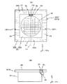
また、図5(A)から明らかなように、第1撥液領域28aの+Y方向側の端部には、そのX方向の中央部に長方形の切り欠きが形成され、この切り欠きと第2撥液領域28bとで囲まれる長方形の空間の内部(切り欠きの内部)に計測プレート30が埋め込まれている。この計測プレート30の長手方向の中央(ウエハテーブルWTBのセンターラインLL上)には、ベースライン計測用の基準マークFMが形成されるとともに、該基準マークのX方向の一側と他側に、基準マークFMの中心に関して対称な配置で一対の空間像計測用のスリットパターン(スリット状の計測用パターン)SLが形成されている。各スリットパターンSLとしては、一例として、Y方向とX方向とに沿った辺を有するL字状のスリットパターン、あるいはX軸及びY方向にそれぞれ延びる2つの直線状のスリットパターンなどを用いることができる。
Further, as is apparent from FIG. 5A, a rectangular notch is formed in the central portion in the X direction at the end portion on the + Y direction side of the first liquid
そして、上記各スリットパターンSL下方のウエハステージWSTの内部には、図5(B)に示されるように、対物レンズ、ミラー、リレーレンズなどを含む光学系よりなる送光系36が収納されたL字状の筐体が、ウエハテーブルWTBからステージ本体91の内部の一部を貫通する状態で、一部埋め込み状態で取り付けられている。送光系36は、図示は省略されているが、上記一対の空間像計測スリットパターンSLに対応して一対設けられている。送光系36は、空間像計測スリットパターンSLを透過した照明光ILを、L字状の経路に沿って導き、Y方向に向けて射出する。
Then, inside the wafer stage WST below each of the slit patterns SL, as shown in FIG. 5B, a
さらに、第2撥液領域28bの上面には、その4辺のそれぞれに沿って所定ピッチで多数の格子線37,38が直接形成されている。これをさらに詳述すると、第2撥液領域28bのX方向の両側の領域には、Yスケール39Y1,39Y2がそれぞれ形成されている。このYスケール39Y1,39Y2はそれぞれ、例えばX方向を長手方向とする格子線38を所定ピッチでY軸に平行な方向(Y方向)に沿って形成してなる、Y方向を周期方向とする反射型の格子(例えば位相型の回折格子)によって構成されている。
Further, on the upper surface of the second liquid
同様に、第2撥液領域28bのY方向の両側の領域には、Xスケール39X1,39X2がそれぞれ形成されている。このXスケール39X1,39X2はそれぞれ、例えばY方向を長手方向とする格子線37を所定ピッチでX軸に平行な方向(X方向)に沿って形成してなる、X方向を周期方向とする反射型の格子(例えば位相型の回折格子)によって構成されている。
Similarly, X scales 39X 1 and 39X 2 are respectively formed in regions on both sides in the Y direction of the second liquid
上記各スケール39Y1,39Y2,39X1,39X2としては、第2撥液領域28bの表面に例えばホログラム等により反射型の回折格子が作成されたものが用いられている。この場合、各スケールには狭いスリット又は溝等から成る格子が目盛りとして所定間隔(ピッチ)で刻まれている。各スケールに用いられる回折格子の種類は限定されるものではなく、機械的に溝等が形成されたもののみならず、例えば、感光性樹脂に干渉縞を焼き付けて作成したものであっても良い。但し、各スケールは、例えば薄板状のガラスに上記回折格子の目盛りを、例えば138nm〜4μmの間のピッチ、例えば1μmピッチで刻んで作成されている。これらスケールは前述の撥液膜(撥水膜)で覆われている。なお、図5(A)では、図示の便宜上から、格子のピッチは、実際のピッチに比べて格段に広く図示されている。その他の図においても同様である。
As each of the scales 39Y 1, 39Y 2, 39X 1 ,
このように、本実施形態では、第2撥液領域28bそのものがスケールを構成するので、第2撥液領域28bの材料として低熱膨張のガラス板を用いることとしたものである。しかし、これに限らず、格子が形成された低熱膨張のガラス板などから成るスケール部材を、局所的な伸縮が生じないように、例えば板ばね(又は真空吸着)等によりウエハテーブルWTBの上面に固定しても良く、この場合には、全面に同一の撥水コートが施された撥水板をプレート28に代えて用いても良い。
Thus, in this embodiment, since the 2nd liquid repellent area |
ウエハテーブルWTBの−Y端面、−X端面には、それぞれ鏡面加工が施され、図2に示される反射面17a,17bが形成されている。干渉計システム118(図7参照)のY軸干渉計16及びX軸干渉計126(図2参照)は、これらの反射面17a,17bにそれぞれ干渉計ビーム(測長ビーム)を投射して、それぞれの反射光を受光する。そして、干渉計16及び126は、各反射面の基準位置(例えば投影ユニットPU側面に配置された参照鏡)からの変位、すなわちウエハステージWSTのXY平面内の位置情報を計測し、この計測値が主制御装置20に供給される。本実施形態では、Y軸干渉計16及びX軸干渉計126として、ともに光軸を複数有する多軸干渉計が用いられており、これらの干渉計16及び126の計測値に基づいて、主制御装置20は、ウエハテーブルWTBのX,Y方向の位置に加え、θx方向の回転情報(ピッチング)、θy方向の回転情報(ローリング)、及びθz方向の回転情報(ヨーイング)も計測可能である。
The -Y end surface and -X end surface of wafer table WTB are mirror-finished to form reflecting
但し、本実施形態では、ウエハステージWST(ウエハテーブルWTB)のXY平面内の位置情報(θz方向の回転情報を含む)は、主として、上述したYスケール、Xスケールなどを含む、後述するエンコーダシステムによって計測され、干渉計16,126の計測値は、そのエンコーダシステムの計測値の長期的変動(例えばスケールの経時的な変形などによる)を補正(キャリブレーション)する場合などに補助的に用いられる。また、Y軸干渉計16は、ウエハ交換のため、後述するアンローディングポジション、及びローディングポジション付近においてウエハテーブルWTBのY方向の位置等を計測するのに用いられる。また、例えばローディング動作とアライメント動作との間、及び/又は露光動作とアンローディング動作との間におけるウエハステージWSTの移動においても、干渉計システム118の計測情報、すなわち5自由度の方向(X方向、Y方向、θx、θy及びθz方向)の位置情報の少なくとも1つが用いられる。なお、干渉計システム118のY軸干渉計16、X軸干渉計126、及び後述の計測ステージMST用のY軸干渉計18、X軸干渉計130は、例えば投影ユニットPUを保持するメインフレームに設けられている。
However, in the present embodiment, position information (including rotation information in the θz direction) in the XY plane of wafer stage WST (wafer table WTB) mainly includes the Y scale, X scale, and the like described later. The measurement values of the
また、本実施形態では、干渉計システム118によって計測されるウエハステージWSTの位置情報が、後述の露光動作やアライメント動作などでは用いられず、主としてエンコーダシステムのキャリブレーション動作(すなわち、計測値の較正)などに用いられるものとしたが、干渉計システム118の計測情報(すなわち、5自由度の方向の位置情報の少なくとも1つ)を、例えば露光動作及び/又はアライメント動作などで用いても良い。この場合、干渉計システム118の計測情報がアライメント演算系20aにも供給される。本実施形態では、エンコーダシステムはウエハステージWSTの3自由度の方向、すなわちX軸、Y軸及びθz方向の位置情報を計測する。そこで、露光動作などにおいて、干渉計システム118の計測情報のうち、エンコーダシステムによるウエハステージWSTの位置情報の計測方向(X方向、Y方向、及びθz方向)と異なる方向、例えばθx方向及び/又はθy方向に関する位置情報のみを用いても良いし、その異なる方向の位置情報に加えて、エンコーダシステムの計測方向と同じ方向(すなわち、X方向、Y方向、及びθz方向の少なくとも1つ)に関する位置情報を用いても良い。また、干渉計システム118はウエハステージWSTのZ方向の位置情報を計測可能としても良い。この場合、露光動作などにおいてZ方向の位置情報を用いても良い。
Further, in the present embodiment, the position information of wafer stage WST measured by
図1の計測ステージMSTは、ステージ本体92上に平板状の計測テーブルMTB及び後述のCDバー46(図6(A)参照)を搭載して構成されている。ステージ本体92には、計測テーブルMTB及びCDバー46のZ方向の位置、及びθx方向、θy方向の傾斜角を制御するZ・レベリング機構(例えば3箇所のボイスコイルモータを含む機構など)が組み込まれている。計測テーブルMTB及びステージ本体92には、各種計測用部材が設けられている。この計測用部材としては、例えば、図2及び図6(A)に示されるように、ピンホール状の受光部を有する照度むらセンサ94、投影光学系PLにより投影されるパターンの空間像(投影像)を計測する空間像計測器96、及び波面収差計測器98などが採用されている。
The measurement stage MST of FIG. 1 is configured by mounting a flat measurement table MTB and a later-described CD bar 46 (see FIG. 6A) on a stage
なお、本実施形態では、投影光学系PLと液体(水)Lqとを介して照明光ILによりウエハWを露光する液浸露光が行われるのに対応して、照明光ILを用いる計測に使用される上記の照度むらセンサ94(及び照度モニタ)、空間像計測器96、並びに波面収差計測器98では、投影光学系PL及び水を介して照明光ILを受光することとなる。
計測ステージMSTのステージ本体92には、図6(B)に示されるように、その−Y方向側の端面に、枠状の取付部材42が固定されている。また、ステージ本体92の−Y方向側の端面には、取付部材42の開口内部のX方向の中心位置近傍に、前述した図5(B)の一対の送光系36に対向し得る配置で、一対の受光系44が固定されている。各受光系44は、リレーレンズなどの光学系と、受光素子、例えばフォトマルチプライヤチューブなどと、これらを収納する筐体とによって構成されている。図5(B)及び図6(B)、並びにこれまでの説明から分かるように、本実施形態では、ウエハステージWSTと計測ステージMSTとが、Y方向に関して所定距離以内に近接した状態(接触状態を含む)では、ウエハステージWSTの計測プレート30の各スリットパターンSLを透過した照明光ILが前述の各送光系36で案内され、計測ステージMSTの各受光系44の受光素子で受光される。すなわち、計測プレート30、送光系36、及び受光系44によって、特開2002−14005号公報(対応する米国特許出願公開第2002/0041377号明細書)などに開示されるものと同様の、空間像計測装置45(図7参照)が構成される。
In the present embodiment, it is used for the measurement using the illumination light IL corresponding to the immersion exposure for exposing the wafer W with the illumination light IL through the projection optical system PL and the liquid (water) Lq. The illuminance unevenness sensor 94 (and the illuminance monitor), the aerial
As shown in FIG. 6B, a frame-shaped
図6(B)の取付部材42上には、断面矩形の棒状部材から成る基準部材としてのコンフィデンシャルバー(以下、「CDバー」と略述する)46がX方向に延設されている。このCDバー46は、フルキネマティックマウント構造によって、計測ステージMSTの取付部材42上にキネマティックに支持されている。
CDバー46は、原器(計測基準)となるため、低熱膨張率のガラスセラミックス、例えば、ショット社のゼロデュア(商品名)などがその素材として採用されている。このCDバー46の上面(表面)は、いわゆる基準平面板と同程度にその平坦度が高く設定されている。また、このCDバー46の長手方向の一側と他側の端部近傍には、図6(A)に示されるように、Y方向を周期方向とする基準格子(例えば回折格子)52がそれぞれ形成されている。この一対の基準格子52は、所定距離(Lとする)を隔ててCDバー46のX方向の中心、すなわち前述のセンターラインCLに関して対称な配置で形成されている。
On the
Since the
また、このCDバー46の上面には、図6(A)に示されるような配置で複数の基準マークMが形成されている。この複数の基準マークMは、Y方向に関して例えば3行の配列で形成され、各行の複数のマークがX方向に関して互いに所定距離だけずれて形成されている。各基準マークMとしては、後述するプライマリライメント系、セカンダリアライメント系によって検出可能な寸法の2次元マークが用いられている。基準マークMはその形状(構成)が前述の図5(A)の基準マークFMと異なっても良い。本実施形態ではプライマリライメント系用の基準マークMは基準マークFMと同一構成であり、かつウエハWのアライメントマークとも同一の構成となっている。一方、セカンダリアライメント系の検出領域は後述のようにX方向に所定範囲で可動であるため、セカンダリアライメント系用の基準マークMは、一例としてX方向、Y方向に所定ピッチでX方向に細長い2次元マークである。複数の基準マークMの形状及び位置関係(間隔等)の情報は、主制御装置20に接続されたアライメント演算系20aに記憶されている。
なお、本実施形態ではCDバー46の表面、及び計測テーブルMTB(前述の計測用部材を含んでも良い)の表面もそれぞれ撥液膜(撥水膜)で覆われている。
A plurality of reference marks M are formed on the upper surface of the
In the present embodiment, the surface of the
図2に示すように、計測テーブルMTBの+Y端面、−X端面にも前述したウエハテーブルWTBと同様の反射面19a,19bが形成されている。干渉計システム118(図7参照)のY軸干渉計18、X軸干渉計130は、これらの反射面19a,19bに、干渉計ビーム(測長ビーム)を投射してそれぞれの反射光を受光することにより、各反射面の基準位置からの変位、すなわち計測ステージMSTの位置情報(例えば、少なくともX方向、Y方向の位置情報とθz方向の回転情報とを含む)を計測し、この計測値が主制御装置20に供給される。
As shown in FIG. 2, reflection surfaces 19a and 19b similar to the wafer table WTB described above are also formed on the + Y end surface and the −X end surface of the measurement table MTB. The Y-
ところで、X軸固定子81及び80のX方向の両端部には、図2に示されるように、ストッパ機構48A,48Bが設けられている。ストッパ機構48A,48Bは、X軸固定子81に設けられた、例えばオイルダンパから成る緩衝装置としてのショックアブソーバ47A,47Bと、X軸固定子80のショックアブソーバ47A,47Bに対向する位置に設けられた開口51A,51Bと、これを開閉するシャッタ49A,49Bとを含んでいる。シャッタ49A,49Bによる開口51A,51Bの開閉状態は、シャッタ49A,49B近傍に設けられた開閉センサ(図7参照)101により検出され、該検出結果が主制御装置20に送られる。
Meanwhile, as shown in FIG. 2,
ここで、前記ストッパ機構48A,48Bの作用について、ストッパ機構48Aを代表的に採り上げて説明する。
図2において、シャッタ49Aが開口51Aを閉塞する状態にある場合には、X軸固定子81とX軸固定子80が接近した場合にも、ショックアブソーバ47Aとシャッタ49Aが接触(当接)することにより、それ以上、X軸固定子80,81同士が接近できなくなる。一方、シャッタ49Aが開かれて開口51Aが開放された場合、X軸固定子81,80が互いに接近すると、ショックアブソーバ47Aの先端部の少なくとも一部を開口51A内に侵入させることができ、X軸固定子81,80同士を接近させることが可能となる。この結果、ウエハテーブルWTBと計測テーブルMTB(CDバー46)とを接触させる(あるいは、300μm程度の距離に近接させる)ことが可能である。
Here, the action of the
In FIG. 2, when the
図2において、X軸固定子80の両端部の−Y側には、間隔検知センサ43A,43Cと衝突検知センサ43B,43Dとが設けられ、X軸固定子81の両端部の+Y側には、Y方向に細長い板状部材41A,41Bが突設されている。間隔検知センサ43A,43Cは、例えば透過型フォトセンサ(例えばLED−フォトトランジストよりなるセンサ)から成り、X軸固定子80とX軸固定子81が接近して、間隔検知センサ43Aの間に板状部材41Aが入り、受光量が減少することから、X軸固定子80,81の間隔が所定距離以下になったことを検知できる。
In FIG. 2,
衝突検知センサ43B,43Dは、間隔検知センサ43A,43Cと同様の光電センサであるが、さらにその奥に配置されている。衝突検知センサ43B,43Dによると、X軸固定子81,80が更に接近し、ウエハテーブルWTBとCDバー46(計測テーブルMTB)とが接触した段階(又は300μm程度の距離に近接した段階)で、センサ間に板状部材41Aの上半部が位置決めされるため、主制御装置20は、そのセンサの受光量が零になるのを検出することで、両テーブルが接触した(又は300μm程度の距離に近接した)ことを検知できる。
The
本実施形態の露光装置100では、図1では図面の錯綜を避ける観点から図示が省略されているが、実際には、図4に示されるように、投影ユニットPUの中心(投影光学系PLの光軸AX、本実施形態では前述の露光領域IAの中心とも一致)を通りかつY軸と平行な直線LV上で、その光軸AXから−Y側に所定距離隔てた位置に検出中心を有するプライマリアライメント系AL1が配置されている。このプライマリアライメント系AL1は、メインフレーム(不図示)に固定されている。プライマリアライメント系AL1を挟んで、X方向の一側と他側には、その直線LVに関してほぼ対称に検出中心が配置されるセカンダリアライメント系AL21,AL22と、セカンダリアライメント系AL23,AL24とがそれぞれ設けられている。すなわち、5つのアライメント系AL1,AL21〜AL24はその検出領域(検出中心)がX方向に関して異なる位置に、すなわちX方向に沿って配置されている。
In the
各セカンダリアライメント系AL2n(n=1〜4)は、セカンダリアライメント系AL24について代表的に示されるように、回転中心Oを中心として図4における時計回り及び反時計回りに所定角度範囲で回動可能なアーム56n(n=1〜4)の先端(回動端)に固定されている。本実施形態では、各セカンダリアライメント系AL2nはその一部(例えば、アライメント光を検出領域に照射し、かつ検出領域内の対象マークから発生する光を受光素子に導く光学系を少なくとも含む)がアーム56nに固定され、残りの一部はメインフレーム(不図示)に設けられる。セカンダリアライメント系AL21〜AL24はそれぞれ、回転中心Oを中心として回動することで、その検出領域のX方向の位置(X位置)が調整される。
Each secondary alignment system AL2 n (n = 1~4), as representatively shown by secondary alignment system AL2 4, times in a predetermined angle range in clockwise and counter-clockwise in FIG. 4 around the rotational center O The movable arm 56 n (n = 1 to 4) is fixed to the tip (rotating end). In the present embodiment, each secondary alignment system AL2 n includes a part thereof (for example, at least an optical system that irradiates the detection region with the alignment light and guides the light generated from the target mark in the detection region to the light receiving element). It is fixed to the
すなわち、セカンダリアライメント系AL21〜AL24はその検出領域(又は検出中心)が独立にX方向に可動である。なお、本実施形態では、アームの回動によりセカンダリアライメント系AL21〜AL24の検出領域のX位置が調整されるものとした。しかしながら、これに限らず、例えばセカンダリアライメント系AL21〜AL24の先端部の光学系をリニアモータ等によってY軸に平行にX方向に移動させて、その移動に伴う光路長の変化を不図示の光学系によって相殺するようにしてもよい。この平行移動方式によれば、各セカンダリアライメント系の検出領域はX軸に平行に移動する。さらに、セカンダリアライメント系AL21〜AL24の先端部の光学系(又はセカンダリアライメント系AL21〜AL24の光学系全体)をリニアモータ方式等でX方向、Y方向に独立に駆動できるようにしてもよい。 That is, the secondary alignment systems AL2 1 to AL2 4 have their detection areas (or detection centers) movable independently in the X direction. In the present embodiment, the X position of the detection region of the secondary alignment systems AL2 1 to AL2 4 is adjusted by rotating the arm. However, the present invention is not limited to this, for example, the optical system at the tip of the secondary alignment systems AL2 1 to AL2 4 is moved in the X direction parallel to the Y axis by a linear motor or the like, and the change in the optical path length due to the movement is not shown. You may make it cancel by the optical system. According to this parallel movement method, the detection area of each secondary alignment system moves parallel to the X axis. Furthermore, as can be driven secondary alignment systems AL2 1 AL24 4 of the tip portion of the optical system (or the whole optical system of the secondary alignment systems AL2 1 ~AL2 4) X direction linear motor system or the like, independently in the Y direction Also good.
また、セカンダリアライメント系AL21〜AL24の検出領域の少なくとも1つをX方向だけでなくY方向にも可動として良い。なお、各セカンダリアライメント系AL2nはその一部の光学系がアーム56nによって移動されるので、不図示のセンサ、例えば干渉計、あるいはエンコーダなどによって、アーム56nに固定されるその一部の光学系の位置情報が計測可能となっている。このセンサは、セカンダリアライメント系AL2nの検出領域のX方向の位置情報を計測するだけでも良いが、他の方向、例えばY方向、及び/又は回転方向(θx及びθy方向の少なくとも一方を含む)の位置情報も計測可能として良い。
Further, at least one of the detection regions of the secondary alignment systems AL2 1 to AL2 4 may be movable not only in the X direction but also in the Y direction. Since each optical system of each secondary alignment system AL2 n is moved by the
前記各アーム56nの上面には、差動排気型のエアベアリングから成るバキュームパッド58n(n=1〜4)が設けられている。また、アーム56nは、例えばモータ等を含む回転駆動機構60n(n=1〜4、図7参照)によって、主制御装置20の指示に応じて回動可能である。主制御装置20は、アーム56nの回転調整後に、各バキュームパッド58nを作動させて各アーム56nをメインフレーム(不図示)に吸着固定する。これにより、各アーム56nの回転角度調整後の状態、すなわち、プライマリアライメント系AL1及び4つのセカンダリアライメント系AL21〜AL24の所望の位置関係が維持される。図7の主制御装置20は、セカンダリアライメント系AL2nの検出領域のX位置を、ウエハ上の検出対象の複数のアライメントマークのX位置がそれらの検出領域内の検出中心付近に同時に設定されるように制御する。
A vacuum pad 58 n (n = 1 to 4) composed of a differential exhaust type air bearing is provided on the upper surface of each
なお、計測フレーム21のアーム56nに対向する部分に磁性体を固定しておき、バキュームパッド58nに代えて電磁石を採用しても良い。
本実施形態では、プライマリアライメント系AL1及び4つのセカンダリアライメント系AL21〜AL24のそれぞれとして、例えば画像処理方式のFIA(Field Image Alignment)系が用いられている。このFIA系では、ウエハ上のレジストを感光させないハロゲンランプ又はキセノンランプ等からのブロードバンドな検出光束を被検マークに照射し、その被検マークからの反射光により受光面に結像された対象マークの像を撮像素子(CCD型又はCMOS型等)を用いて撮像し、それらの撮像信号を出力する。この場合には、撮像素子内の所定画素の位置を基準として被検マークの像の位置を検出するが、その代わりに、FIA系内に指標マークを設け、この指標マークの像の位置を基準としてその被検マークの像を検出してもよい。アライメント系AL1及びAL21〜AL24を介して求められる被検マークの像の基準位置からのずれ量の情報は、図7の主制御装置20に供給される。
A magnetic material may be fixed to a part of the measurement frame 21 facing the
In the present embodiment, for example, an image processing type FIA (Field Image Alignment) system is used as each of the primary alignment system AL1 and the four secondary alignment systems AL2 1 to AL2 4 . In this FIA system, an object mark formed on a light-receiving surface by irradiating a detection mark with a broadband detection light beam from a halogen lamp or a xenon lamp that does not sensitize a resist on a wafer, and reflected light from the inspection mark These images are picked up using an image pickup device (CCD type or CMOS type), and the image pickup signals are output. In this case, the position of the image of the test mark is detected with reference to the position of a predetermined pixel in the image sensor. Instead, an index mark is provided in the FIA system, and the position of the image of the index mark is used as a reference. As an example, an image of the test mark may be detected. Information on the amount of deviation from the reference position of the image of the test mark obtained via the alignment systems AL1 and AL2 1 to AL2 4 is supplied to the
図3(A)は、5眼のアライメント系AL1及びAL21〜AL24の概略構成を概念的に示す。図3(A)は、アライメント系AL1及びAL21〜AL24がそれぞれ図6(A)のCDバー46上の基準マークM1,M21,M22,M23,M24(図6(A)の基準マークMのいずれかに対応する)を検出している状態を示している。図3(A)において、プライマリアライメント系AL1は、被検マークからの反射光を受光する第1対物レンズ系5aと、その反射光を分岐するビームスプリッタ5bと、開口絞り(不図示)と、第1対物レンズ系5aからの反射光を集光して被検マークの拡大像を形成する第2対物レンズ系5cと、その像を撮像する2次元の撮像素子5dとを含んでいる。実際には、例えば第1対物レンズ系5cとビームスプリッタ5bとの間に、不図示の光源からの照明光を被検マークに導くビームスプリッタ(不図示)が備えられている。また、撮像素子5dの撮像面と共役な被検面上の視野が、プライマリアライメント系AL1の検出領域AL1fである。
FIG. 3A conceptually shows a schematic configuration of the five-eye alignment systems AL1 and AL2 1 to AL2 4 . In FIG. 3A, alignment systems AL1 and AL2 1 to AL2 4 are respectively connected to fiducial marks M1, M2 1 , M2 2 , M2 3 , M2 4 on
セカンダリアライメント系AL21〜AL24も、基本的な構成はプライマリアライメント系AL1と同様であり、被検マークの拡大像を形成する対物レンズ系と、その像を撮像する2次元の撮像素子5dとを含んでいる。また、セカンダリアライメント系AL21〜AL24の各撮像素子の撮像面と共役な被検面上の視野が検出領域AL1f〜AL24fである。さらに、一例として、プライマリアライメント系AL1の撮像素子5dの中心の画素(原点)に対応する被検面上の点がプライマリアライメント系AL1の検出中心となる。また、プライマリアライメント系AL1の検出中心からX方向に所定の可変の距離(後述のセカンダリベースライン)だけ離れた位置にあるマークを、セカンダリアライメント系AL21〜AL24の撮像素子5dで検出している場合、そのマークの中心が各セカンダリアライメント系AL21〜AL24の検出中心となる。
The secondary alignment systems AL2 1 to AL2 4 are similar in basic configuration to the primary alignment system AL1, and include an objective lens system that forms an enlarged image of the test mark, and a two-
アライメント系AL1及びAL21〜AL24の撮像素子5dからの撮像信号はそれぞれ検出信号処理部131A,131B,131C,131D,131Eに供給される。検出信号処理部131A〜131Eでは、各撮像素子5dの撮像信号を所定範囲で被検面上でのY方向、X方向に対応する方向に積算して、それぞれX方向及びY方向に周期的なマークの像の撮像信号SX,SYを生成し、撮像信号SX,SYをオフセット補正部132に供給する。
Imaging signals from the
さらに、検出信号処理部131A〜131Eは、それぞれの撮像信号SX,SYを例えば所定の閾値でスライスして、対応するマークの検出中心に対するX方向、Y方向の位置ずれ量を求め、この位置ずれ量の情報をオフセット補正部132を介して図7のアライメント演算系20aに供給する。アライメント演算系20aでは、各位置ずれ量を予め求められている各アライメント系AL21〜AL24の検出中心の座標に加算することで、被検マークのステージ座標系(X,Y)での座標値を求めることができる。
Further, the detection
なお、セカンダリアライメント系AL21〜AL24の検出領域AL21f〜AL24fはX方向に所定範囲内で可動である。従って、例えばセカンダリアライメント系AL21〜AL24の全体を可動にした場合には、セカンダリアライメント系AL21〜AL24の内部で光路長が変化することはないので、セカンダリアライメント系AL21〜AL24の構成はプライマリアライメント系AL1と同一構成でもよい。一方、例えばセカンダリアライメント系AL1〜AL24の先端部等の光学系のみを可動にした場合には、その後に光路長の変化を相殺するための光学系等を組み込む必要がある。 The detection region AL2 1 f~AL2 4 f of secondary alignment systems AL2 1 AL24 4 is movable within a predetermined range in the X direction. Thus, for example, when the entire secondary alignment systems AL2 1 AL24 4 to move, since the optical path length within the secondary alignment systems AL2 1 AL24 4 is not changed, the secondary alignment systems AL2 1 AL24 4 The configuration may be the same as that of the primary alignment system AL1. On the other hand, for example, when only the optical system such as the tip of the secondary alignment systems AL 1 to AL2 4 is movable, it is necessary to incorporate an optical system for canceling the change in the optical path length thereafter.
また、アライメント系AL1及びAL21〜AL24のベストフォーカス位置は、実際にはそれぞれの撮像素子5dから得られる被検マークの像に対応する部分の撮像信号SX,SYが以下のような3つの評価基準A,B,Cのいずれかに合致するときの、被検面のZ方向の位置(Z位置又はフォーカス位置)である。
(A)その撮像信号のコントラストが最も高くなるとき。例えば、図3(C)に示すように、Y方向のマークの像に対応する撮像信号SYのコントラストが、点線のように最も高くなったときがベストフォーカス位置である。撮像信号SX,SYでベストフォーカス位置が僅かに異なる場合には、その平均値をベストフォーカス位置としてもよい。
In addition, the best focus positions of the alignment systems AL1 and AL2 1 to AL2 4 are actually three imaging signals SX and SY corresponding to the image of the test mark obtained from each
(A) When the contrast of the imaging signal is the highest. For example, as shown in FIG. 3C, the best focus position is when the contrast of the imaging signal SY corresponding to the mark image in the Y direction is highest as shown by the dotted line. If the best focus position is slightly different between the imaging signals SX and SY, the average value may be used as the best focus position.
(B)その撮像信号の横方向の位置に関する変化率(立ち上がり)が最も急峻になるとき。
(C)評価基準A及びBの加重平均が最も高くなるとき。
これらの評価基準のどれを適用するかは、例えば被検マークがCDバー46上のマークである場合と、ウエハW上のアライメントマーク(以下、ウエハマークという)である場合とで異なってもよい。また、被検マークが振幅マークか位相マークかに応じて、異なる評価基準を適用してもよい。本実施形態では、一例として評価基準Aの、被検マークの像の撮像信号のコントラストが最も高くなるときの被検面のZ位置をベストフォーカス位置とする。なお、凹凸マーク(位相マーク)であるウエハマークの評価基準として、評価基準Bを適用してもよい。
(B) When the rate of change (rise) of the image signal in the horizontal direction is the steepest.
(C) When the weighted average of evaluation criteria A and B is the highest.
Which of these evaluation criteria is applied may differ, for example, when the test mark is a mark on the
上記のどの評価基準を用いる場合でも、ベストフォーカス位置を決定するためには、被検マークの像を撮像素子5dで撮像した状態で、被検面をZ方向にスキャンする必要がある。しかしながら、1つのマークを検出する度に一定量のZ方向のスキャン動作を実行するのでは、スループットが低下する。そこで、被検面とベストフォーカス位置とのZ方向のずれ量であるデフォーカス量を計測するために、アライメント系AL1及びAL21〜AL24には、それぞれ同一構成のオートフォーカス系(以下、AF系という)6A,6B,6C,6D,6Eが装着されている。このAF系により、マークがZ方向のプラス側、マイナス側のいずれにどの程度の量ずれているのかをしり、マークを必要な量だけZ方向にすばやく移動させることができる。このアライメント系用のAF系6A〜6Eは、図4等では図示を省略している。
In any of the above evaluation criteria, in order to determine the best focus position, it is necessary to scan the test surface in the Z direction in a state where the image of the test mark is captured by the
一例として、AF系6Aは、プライマリアライメント系AL1のビームスプリッタ5b(又は部分反射ミラー等)で分岐(又は反射)された光を瞳面近傍で2分割して反射する瞳分割用のミラー6bと、ミラー6bからの光を集光して被検面のパターンの2つの拡大像を形成する集光レンズ系6cと、その2つの拡大像を撮像する1次元のラインセンサ(2次元の撮像素子でもよい)6dとを含んで構成されている。実際には、AF系6Aには、不図示の光源からの照明光によって照明された所定パターン(スリットパターン等)を通過した光をビームスプリッタ5b側に送光する光学部材(不図示)が組み込まれており、そのラインセンサ6d上にはその所定パターンの2つの像が形成される。ラインセンサ6dの検出信号は検出信号処理部131Aに供給される。この場合、被検面がZ方向に変位すると、ラインセンサ6d上のパターンの2つの結像位置の間隔(シフト量の差分)が変化するため、検出信号処理部131Aでは、その間隔に対応する図3(B)の実線で示すフォーカス信号FSをオフセット補正部132に供給する。
As an example, the
他のAF系6B〜6EもAF系6Aと同様に構成され、AF系6B〜6Eのラインセンサからの検出信号が供給された検出信号処理部131B〜131Eは、それぞれセカンダリアライメント系AL21〜AL24の撮像素子5dに対するベストフォーカス位置に対する被検面のデフォーカス量に対応するフォーカス信号をオフセット補正部132に供給する。なお、AF系6A〜6Eとして使用できるオートフォーカス系のより詳細な構成は、例えば特開2004−335971号公報に開示されている。また、AF系6A〜6Eとしては、例えば特開平7−321030号公報に開示されているような、瞳面のほぼ半面の光束を用いるオートフォーカス系等も使用可能である。
The
オフセット補正部132は、それらのフォーカス信号に予め求められている係数を乗じて得られるアライメント系AL1及びAL21〜AL24毎のデフォーカス量の情報を主制御装置20に供給する。主制御装置20は、そのデフォーカス量の情報を用いて、後述のように被検面がそれぞれアライメント系AL1及びAL21〜AL24のベストフォーカス位置に配置されるように、ウエハステージWST又は計測ステージMST内のZ・レベリング機構を駆動してウエハW又はCDバー46のレベリングを行う。
The offset
また、後述のAF系6A〜6Eを介して得られるフォーカス信号のキャリブレーション時には、オフセット補正部132では、AF系6A〜6Eの検出信号処理部131A〜131Eからのフォーカス信号FS等が、実際に求められたベストフォーカス位置Zf1等で0となるようにオフセットFSOF1 等を求めて、検出信号処理部131A〜131Eに供給する。検出信号処理部131A〜131Eでは、元のフォーカス信号にそのオフセットを加算して補正されたフォーカス信号をオフセット補正部132に供給する。本実施形態のセカンダリアライメント系AL21〜AL24の検出領域のX方向の位置を変えた後には、AF系6B〜6Eを介して得られるフォーカス信号のデフォーカス量が実際のデフォーカス量と異なる恐れがあるため、そのフォーカス信号のキャリブレーションを行うことが好ましい。
Further, during calibration of focus signals obtained via
なお、上記各アライメント系としては、FIA系に限らず、例えばコヒーレントな検出光を対象マークに照射し、その対象マークから発生する散乱光又は回折光を検出する、あるいはその対象マークから発生する2つの回折光(例えば同次数の回折光、あるいは同方向に回折する回折光)を干渉させて検出するアライメントセンサを単独であるいは適宜組み合わせて用いることは勿論可能である。これらの場合にも、被検面のベストフォーカス位置からのずれ量を計測するAF系6A〜6Eと同様のオートフォーカス系が設けられる。
The alignment system is not limited to the FIA system. For example, the target mark is irradiated with coherent detection light to detect scattered light or diffracted light generated from the target mark, or 2 generated from the target mark. Of course, it is possible to use an alignment sensor that detects two diffracted lights (for example, diffracted lights of the same order or diffracted in the same direction) by interference alone or in appropriate combination. Also in these cases, an autofocus system similar to the
また、本実施形態では5つのアライメント系AL1、AL21〜AL24を設けているため、アライメントを効率的に行うことができる。しかしながら、アライメント系の数は5つに限られるものでなく、2つ以上かつ4つ以下、あるいは6つ以上でも良いし、奇数ではなく偶数でも良い。
本実施形態の露光装置100では、図4に示されるように、前述したノズルユニット32の周囲を四方から囲む状態で、エンコーダシステムの4つのヘッドユニット62A〜62Dが配置されている。これらのヘッドユニット62A〜62Dを構成する複数のYヘッド64及びXヘッド66は、図4では2点鎖線で示すように、メインフレーム(不図示)の底面に固定されている。
In the present embodiment, since five alignment systems AL1, AL2 1 to AL2 4 are provided, alignment can be performed efficiently. However, the number of alignment systems is not limited to five, and may be two or more and four or less, or six or more, or may be an even number instead of an odd number.
In the
図4において、ヘッドユニット62A,62Cは、投影ユニットPUの+X側、−X側にそれぞれX方向に沿って投影光学系PLの光軸AXを通りかつX軸と平行な直線LH上に所定間隔で配置された複数(ここでは6個)のYヘッド64を備えている。Yヘッド64は、それぞれ前述の図5(A)のYスケール39Y1又は39Y2を用いて、ウエハステージWST(ウエハテーブルWTB)のY方向の位置(Y位置)を計測する。また、ヘッドユニット62B,62Dは、投影ユニットPUの+Y側、−Y側にそれぞれY方向に沿って光軸AXを通りかつY軸と平行な直線LV上にほぼ所定間隔で配置された複数(ここでは7個及び11個(ただし、図4ではその11個のうちのプライマリアライメント系AL1と重なる3個は不図示))のXヘッド66を備えている。Xヘッド66は、それぞれ前述の図5(A)のXスケール39X1又は39X2を用いて、ウエハステージWST(ウエハテーブルWTB)のX方向の位置(X位置)を計測する。
In FIG. 4,
従って、図4のヘッドユニット62A及び62Cは、それぞれ図5(A)のYスケール39Y1及び39Y2を用いて、ウエハステージWST(ウエハテーブルWTB)のY位置を計測する多眼(ここでは6眼)のY軸のリニアエンコーダ(以下、適宜、Yエンコーダと略述する)70A及び70C(図7参照)を構成する。Yエンコーダ70A,70Cはそれぞれ複数のYヘッド64の計測値の切り替え(詳細後述)を行う切り替え制御部を備えている。ここで、ヘッドユニット62A,62Cが備える隣接するYヘッド64(すなわち、Yヘッド64から照射される計測ビーム)の間隔は、前述のYスケール39Y1,39Y2のX方向の幅(より正確には、格子線38の長さ)よりも狭く設定されている。
Therefore, the
また、ヘッドユニット62B及び62Dは、基本的にそれぞれ前述のXスケール39X1及び39X2を用いて、ウエハステージWST(ウエハテーブルWTB)のX位置を計測する、多眼(ここでは、7眼及び11眼)のX軸のリニアエンコーダ(以下、適宜、Xエンコーダと略述する)70B及び70D(図7参照)を構成する。Xエンコーダ70B,70Dはそれぞれ複数のXヘッド66の計測値の切り替えを行う切り替え制御部を備えている。なお、本実施形態では、例えば後述するアライメント時などにヘッドユニット62Dが備える11個のXヘッド66のうちの2個のXヘッド66が、Xスケール39X1及び39X2に同時に対向する場合がある。この場合には、Xスケール39X1及び39X2とこれに対向するXヘッド66とによって、Xリニアエンコーダ70B及び70Dが構成される。
Further,
ヘッドユニット62B,62Dがそれぞれ備える隣接するXヘッド66(計測ビーム)の間隔は、前述のXスケール39X1,39X2のY方向の幅(より正確には、格子線37の長さ)よりも狭く設定されている。
さらに、図4のセカンダリアライメント系AL21の−X側、セカンダリアライメント系AL24の+X側に、プライマリアライメント系AL1の検出中心を通るX軸に平行な直線上かつその検出中心に対してほぼ対称に検出点が配置されるYヘッド64y1,64y2がそれぞれ設けられている。Yヘッド64y1,64y2の間隔は、前述した距離L(図6(A)の基準格子52のY方向の間隔)にほぼ等しく設定されている。Yヘッド64y1,64y2は、ウエハステージWST上のウエハWの中心が上記直線LV上にある図4に示される状態では、Yスケール39Y2,39Y1にそれぞれ対向するようになっている。後述するアライメント動作の際などでは、Yヘッド64y1,64y2に対向してYスケール39Y2,39Y1がそれぞれ配置され、このYヘッド64y1,64y2(すなわち、これらYヘッド64y1,64y2を含むYエンコーダ70C,70A)によってウエハステージWSTのY位置(及びθz方向の角度)が計測される。
The distance between adjacent X heads 66 (measurement beams) included in each of the
Furthermore, the secondary alignment systems AL2 1 on the -X side of Figure 4, the + X side of secondary alignment system AL2 4, substantially against parallel straight line and the detection center in the X axis passing through the detection center of primary alignment system AL1 symmetry Y heads 64y 1 and 64y 2 in which detection points are arranged are respectively provided. The distance between the Y heads 64y 1 and 64y 2 is set to be approximately equal to the distance L described above (the distance in the Y direction of the reference grating 52 in FIG. 6A). The Y heads 64y 1 and 64y 2 face the Y scales 39Y 2 and 39Y 1 in the state shown in FIG. 4 where the center of the wafer W on the wafer stage WST is on the straight line LV. In case of an alignment operation and the like to be described later, Y heads 64y opposite to 1, 64y 2 Y scales 39Y 2, 39Y 1 are placed respectively, the Y heads 64y 1, 64y 2 (i.e., they Y heads 64y 1, 64y 2 ), the Y position (and the angle in the θz direction) of wafer stage WST is measured.
また、本実施形態では、セカンダリアライメント系の後述するベースライン計測時などに、図6(A)のCDバー46の一対の基準格子52とYヘッド64y1,64y2とがそれぞれ対向し、Yヘッド64y1,64y2と対向する基準格子52とによって、CDバー46のY位置が、それぞれの基準格子52の位置で計測される。以下では、基準格子52にそれぞれ対向するYヘッド64y1,64y2によって構成されるリニアエンコーダをYエンコーダ70E,70F(図7参照)と呼ぶ。
In the present embodiment, the pair of
上述した6つのエンコーダ70A〜70Fの計測値は、主制御装置20及びアライメント演算系20aに供給され、主制御装置20は、エンコーダ70A〜70Dの計測値に基づいて、ウエハテーブルWTBのXY平面内の位置を制御するとともに、Yエンコーダ70E,70Fの計測値に基づいて、CDバー46のθz方向の回転を制御する。
本実施形態の露光装置100では、図4に示されるように、照射系90a及び受光系90bから成る、例えば特開平6−283403号公報(対応する米国特許第5,448,332号明細書)等に開示されるものと同様の構成の斜入射方式の多点焦点位置検出系(以下、多点AF系と略述する)が設けられている。本実施形態では、一例として、前述のヘッドユニット62Cの−X端部の−Y側に照射系90aが配置され、これに対向する状態で、前述のヘッドユニット62Aの+X端部の−Y側に受光系90bが配置されている。
The measurement values of the six
In the
図4の多点AF系(90a,90b)の複数の検出点は、被検面上でX方向に沿って所定間隔で配置される。本実施形態では、例えば1行M列(Mは検出点の総数)又は2行N列(Nは検出点の総数の1/2)の行マトリックス状に配置される。図4中では、それぞれ検出ビームが照射される複数の検出点を、個別に図示せず、照射系90a及び受光系90bの間でX方向に延びる細長い検出領域AFとして示している。この検出領域AFは、X方向の長さがウエハWの直径と同程度に設定されているので、ウエハWをY方向に1回スキャンするだけで、ウエハWのほぼ全面でZ方向の位置情報(面位置情報)を計測できる。また、この検出領域AFは、Y方向に関して、前述の液浸領域14(露光領域IA)とアライメント系(AL1,AL21〜AL24)の検出領域との間に配置されているので、多点AF系とアライメント系とでその検出動作を並行して行うことが可能となっている。多点AF系は、投影ユニットPUを保持するメインフレームに設けても良いが、別の支持部材を介して支持してもよい。
A plurality of detection points of the multipoint AF system (90a, 90b) in FIG. 4 are arranged at predetermined intervals along the X direction on the surface to be detected. In the present embodiment, for example, they are arranged in a row matrix of 1 row and M columns (M is the total number of detection points) or 2 rows and N columns (N is 1/2 of the total number of detection points). In FIG. 4, a plurality of detection points irradiated with the detection beams are not shown individually, but are shown as elongated detection areas AF extending in the X direction between the
なお、複数の検出点は1行M列又は2行N列で配置されるものとしたが、行数及び/又は列数はこれに限られない。
本実施形態の露光装置100は、多点AF系(90a,90b)の複数の検出点のうち両端に位置する検出点の近傍、すなわち検出領域AFの両端部近傍に、前述の直線LVに関して対称な配置で、各一対のZ位置計測用の面位置センサ(以下、Zセンサと略述する)72a,72b、及び72c,72dが設けられている。これらのZセンサ72a〜72dは、例えばメインフレームの下面に固定されている。Zセンサ72a〜72dとしては、ウエハテーブルWTBに対し上方から光を照射し、その反射光を受光してその光の照射点におけるウエハテーブルWTB表面のXY平面に直交するZ方向の位置情報を計測するセンサ、一例としてCDドライブ装置などで用いられる光ピックアップのような構成の光学式の変位センサ(CDピックアップ方式のセンサ)が用いられている。
In addition, although the some detection point shall be arrange | positioned by 1 row M column or 2 rows N columns, the number of rows and / or the number of columns is not restricted to this.
The
さらに、前述したヘッドユニット62Cは、複数のYヘッド64を結ぶX方向の直線LHを挟んで一側と他側に位置する、直線LHに平行な2本の直線上にそれぞれ沿って且つ所定間隔で配置された複数(ここでは各6個、合計で12個)のZセンサ74i,j(i=1,2、j=1,2,……,6)を備えている。この場合、対を成すZセンサ741,j、742,jは、上記直線LHに関して対称に配置されている。さらに、複数対(ここでは6対)のZセンサ741,j、742,jと複数のYヘッド64とは、X方向に関して交互に配置されている。各Zセンサ74i,jとしては、例えば、前述のZセンサ72a〜72dと同様のCDピックアップ方式のセンサが用いられている。
Further, the above-described
ここで、直線LHに関して対称な位置にある各対のZセンサ741,j,742,jの間隔は、前述したZセンサ72c,72dの間隔と同一間隔に設定されている。また、一対のZセンサ741,4,742,4は、Zセンサ72a,72bと同一の、Y方向に平行な直線上に位置している。
また、前述したヘッドユニット62Aは、前述の直線LVに関して、上述の複数のZセンサ74i,jと対称に配置された複数、ここでは12個のZセンサ76p,q(p=1,2、q=1,2,……,6)を備えている。各Zセンサ76p,qとしては、例えば、前述のZセンサ72a〜72dと同様のCDピックアップ方式のセンサが用いられている。また、一対のZセンサ761,3,762,3は、Zセンサ72c,72dと同一のY方向の直線上に位置している。Zセンサ74i,j及び76p,qは計測フレーム21の底面に固定されている。
Here, 1 Z sensor 74 of each pair in a symmetrical position, j, 74 2, interval j with respect to straight line LH,
Further, the
なお、図4では、計測ステージMSTの図示が省略されるとともに、その計測ステージMSTと先端レンズ191との間に保持される水Lqで形成される液浸領域14が示されている。また、この図4において、符号78は、多点AF系(90a,90b)のビーム路近傍に所定温度に温度調整されたドライエアーを、図4中の白抜き矢印で示されるように、例えばダウンフローにて送風する局所空調システムを示す。また、符号UPは、ウエハテーブルWTB上のウエハのアンロードが行われるアンロードポジションを示し、符号LPはウエハテーブルWTB上へのウエハのロードが行われるローディングポジションを示す。本実施形態では、アンロードポジションUPと、ローディングポジションLPとは、直線LVに関して対称に設定されている。なお、アンロードポジションUPとローディングポジションLPとを同一位置としても良い。
In FIG. 4, illustration of the measurement stage MST is omitted, and an
図7には、露光装置100の制御系の主要な構成が示されている。この制御系は、装置全体を統括的に制御するマイクロコンピュータ(又はワークステーション)から成る主制御装置20を中心として構成されている。なお、図7においては、前述した照度むらセンサ94、空間像計測器96及び波面収差計測器98などの計測ステージMSTに設けられた各種センサが、まとめてセンサ群9として示されている。
FIG. 7 shows the main configuration of the control system of the
上述のようにして構成された本実施形態の露光装置100では、前述したようなウエハテーブルWTB上のXスケール、Yスケールの配置及び前述したようなXヘッド、Yヘッドの配置を採用したことから、図8(A)及び図8(B)などに例示されるように、ウエハステージWSTの有効ストローク範囲(すなわち、本実施形態では、アライメント及び露光動作のために移動する範囲)では、必ず、Xスケール39X1,39X2とヘッドユニット62B,62D(Xヘッド66)とがそれぞれ対向し、かつYスケール39Y1,39Y2とヘッドユニット62A,62C(Yヘッド64)又はYヘッド64y1,64y2とがそれぞれ対向するようになっている。なお、図8(A)及び図8(B)中では、対応するXスケール又はYスケールに対向したヘッドが丸で囲んで示されている。
The
このため、主制御装置20は、前述のウエハステージWSTの有効ストローク範囲では、エンコーダ70A〜70Dの少なくとも3つの計測値に基づいて、ステージ駆動系124を構成する各モータを制御することで、ウエハステージWSTのXY平面内の位置情報(θz方向の回転情報を含む)を、高精度に制御することができる。エンコーダ70A〜70Dの計測値が受ける空気揺らぎの影響は、干渉計に比べては無視できるほど小さいので、空気揺らぎに起因する計測値の短期安定性は、干渉計に比べて格段に良い。なお、本実施形態では、ウエハステージWSTの有効ストローク範囲及びスケールのサイズ(すなわち、回折格子の形成範囲)などに応じて、ヘッドユニット62B,62D,62A,62Cのサイズ(例えば、ヘッドの数及び/又は間隔など)を設定している。従って、ウエハステージWSTの有効ストローク範囲では、4つのスケール39X1,39X2、39Y1,39Y2が全てヘッドユニット62B,62D,62A,62Cとそれぞれ対向するが、4つのスケールが全て対応するヘッドユニットと対向しなくても良い。
Therefore,
例えば、Xスケール39X1,39X2の一方、及び/又はYスケール39Y1,39Y2の一方がヘッドユニットから外れても良い。Xスケール39X1,39X2の一方、又はYスケール39Y1,39Y2の一方がヘッドユニットから外れる場合、ウエハステージWSTの有効ストローク範囲では3つのスケールがヘッドユニットと対向するので、ウエハステージWSTのX軸、Y軸及びθz方向の位置情報を常時計測可能である。また、Xスケール39X1,39X2の一方、及びYスケール39Y1,39Y2の一方がヘッドユニットから外れる場合、ウエハステージWSTの有効ストローク範囲では2つのスケールがヘッドユニットと対向するので、ウエハステージWSTのθz方向の位置情報は常時計測できないが、X軸及びY方向の位置情報は常時計測可能である。この場合、干渉計システム118によって計測されるウエハステージWSTのθz方向の位置情報を併用して、ウエハステージWSTの位置制御を行っても良い。
For example, one of the X scales 39X 1 and 39X 2 and / or one of the Y scales 39Y 1 and 39Y 2 may be detached from the head unit. When one of the X scales 39X 1 and 39X 2 or one of the Y scales 39Y 1 and 39Y 2 deviates from the head unit, the three scales face the head unit in the effective stroke range of the wafer stage WST. Position information in the X axis, Y axis, and θz directions can always be measured. Further, when one of the X scales 39X 1 and 39X 2 and one of the Y scales 39Y 1 and 39Y 2 are out of the head unit, the two scales face the head unit in the effective stroke range of the wafer stage WST. Position information in the θz direction of WST cannot always be measured, but position information in the X axis and Y direction can always be measured. In this case, position control of wafer stage WST may be performed using the position information of wafer stage WST in the θz direction measured by
また、図8(A)中に白抜き矢印で示されるようにウエハステージWSTをX方向に駆動する際、そのウエハステージWSTのY方向の位置を計測するYヘッド64が、同図中に矢印e1,e2で示されるように、隣のYヘッド64に順次切り換わる。例えば、実線の丸で囲まれるYヘッド64から点線の丸で囲まれるYヘッド64へ切り換わる。このため、その切り換わりの前後で、図7のYエンコーダ70A,70C内の切り替え制御部によって計測値が引き継がれる。すなわち、本実施形態では、このYヘッド64の切り換え及び計測値の引継ぎを円滑に行うために、前述の如く、ヘッドユニット62A,62Cが備える隣接するYヘッド64の間隔を、Yスケール39Y1,39Y2のX方向の幅よりも狭く設定したものである。
In addition, when the wafer stage WST is driven in the X direction as indicated by a white arrow in FIG. 8A, the
また、本実施形態では、前述の如く、ヘッドユニット62B,62Dが備える隣接するXヘッド66の間隔は、前述のXスケール39X1,39X2のY方向の幅よりも狭く設定されている。従って、上述と同様に、図8(B)中に白抜き矢印で示されるようにウエハステージWSTをY方向に駆動する際、そのウエハステージWSTのX方向の位置を計測するXヘッド66が、順次隣のXヘッド66に切り換わり(例えば実線の丸で囲まれるXヘッド66から点線の丸で囲まれるXヘッド66へ切り換わる)、その切り換わりの前後で図7のXエンコーダ70B,70D内の切り替え制御部によって計測値が引き継がれる。
In the present embodiment, as described above, the interval between adjacent X heads 66 included in the
また、エンコーダ70A〜70FのYヘッド64は、一例として対応するYスケール39Y1,39Y2に1対のレーザビームを照射する照射系と、それらのスケールから発生する1対の回折光を同軸に合成して干渉光として検出する受光系とを含んで構成されている。さらに、Yヘッド64には、位相が90°異なる干渉光を検出する光学系も組み込まれており、2相の検出信号を用いて内挿を行うことによって、それらのスケールのピッチの1/2よりもかなり細かい分解能で、変位計測を行うことができる。エンコーダ70A〜70FのXヘッド66も同様に構成されている。
In addition, the
以下、本実施形態の図1の露光装置100において、図7の主制御装置20の制御のもとで1ロットのウエハに順次レチクルRのパターンの像を露光する際の動作の一例につき、図17及び図18のフローチャートを参照して説明する。
先ず図17のステップ301において、図1のレチクルステージRST上にレチクルRをロードし、主制御装置20は、不図示の露光データファイルよりレチクルRの照明条件及び投影光学系PLの開口数等の露光条件を読み出して、照明系10等の設定を行う。また、主制御装置20は、その露光データファイルより露光対象のウエハのショット配列の情報を読み出し、このショット配列の情報から、ウエハ上のショット領域のX方向の配列ピッチ、即ちウエハ上の各ショット領域に付設されているウエハマークのX方向の間隔(設計上の間隔)を求める。
Hereinafter, in the
First, in
ウエハのショット配列は、一例として図13(C)に示すように設定され、ウエハW上の全部のショット領域から選ばれた例えば黒色で区別される16個のショット領域よりなるアライメントショット(サンプルショット)ASに付設されたウエハマークをアライメント系AL1,AL21〜AL24で計測するものとする。この場合、ウエハW上のアライメントショットASは、+Y方向から順にX方向に4つのショット領域の幅を配列ピッチとして、3つのアライメントショット、5つのアライメントショット、5つのアライメントショット、及び3つのアライメントショットから構成されている。なお、ウエハマークは、ショット領域内に形成されていてもよいが、本実施形態では、ウエハマークはショット領域間のストリートラインに形成されているものとする。 The wafer shot arrangement is set as shown in FIG. 13C as an example, and an alignment shot (sample shot) consisting of 16 shot areas distinguished from, for example, black selected from all shot areas on the wafer W. ) The wafer mark attached to the AS is measured by the alignment systems AL1, AL2 1 to AL2 4 . In this case, the alignment shot AS on the wafer W has three alignment shots, five alignment shots, five alignment shots, and three alignment shots in the order of the width of four shot regions in the X direction from the + Y direction. Consists of. Although the wafer mark may be formed in the shot area, in the present embodiment, the wafer mark is formed on a street line between the shot areas.
また、前工程でのアライメント系AL1,AL21〜AL24の配置が図9の状態であるとする。そして、プライマリアライメント系AL1の検出中心に対するセカンダリアライメント系AL21,AL22,AL23,AL24の検出中心のX方向の間隔、即ちセカンダリベースラインSBL1,SBL2,SBL3,SBL4が、図10に示すようにそのウエハマークのX方向の間隔の所定の整数倍となるように、セカンダリアライメント系AL21〜AL24を駆動して固定する。一例として、セカンダリベースラインSBL1,SBL2,SBL3,SBL4の初期値は、そのウエハマークのX方向の間隔の8倍、4倍、4倍、及び8倍であり(図13(C)参照)、これらの値の情報はアライメント演算系20aにも供給される。この結果、プライマリアライメント系AL1及びセカンダリアライメント系AL21〜AL24は、ウエハW上のアライメントショットASの計測対象のウエハマークの配置に合わせて、そのX方向の位置調整が行われたことになる。なお、この段階では、セカンダリアライメント系AL21〜AL24の検出中心のX方向の間隔には、設定誤差が含まれている。
Further, it is assumed that the arrangement of alignment systems AL1, AL2 1 to AL2 4 in the previous process is in the state shown in FIG. The intervals in the X direction of the detection centers of the secondary alignment systems AL2 1 , AL2 2 , AL2 3 , AL2 4 with respect to the detection center of the primary alignment system AL1, that is, secondary base lines SBL1, SBL2, SBL3, SBL4 are shown in FIG. As described above, the secondary alignment systems AL2 1 to AL2 4 are driven and fixed so as to be a predetermined integer multiple of the interval between the wafer marks in the X direction. As an example, the initial values of the secondary baselines SBL1, SBL2, SBL3, and SBL4 are 8 times, 4 times, 4 times, and 8 times the interval in the X direction of the wafer mark (see FIG. 13C). Information on these values is also supplied to the
次のステップ302において、図3(A)のアライメント系AL1,AL21〜AL24用のAF系6A〜6Eのキャリブレーションを行うために、図2の状態(ただし、ウエハWは載置されていない)から計測ステージMSTを駆動して、計測ステージMSTのCDバー46の複数の基準マークM1,M21〜M24をアライメント系AL1,AL21〜AL24の検出領域に移動する。そして、計測ステージMSTのZ・レベリング機構を介して、図3(A)の状態からCDバー46の上面(マーク形成面)を、それまでの工程で求められているアライメント系AL1,AL21〜AL24のベストフォーカス位置の範囲よりも広い範囲でZ方向にスキャンする。さらに、このスキャンに同期して、主制御装置20の制御のもとでオフセット補正部132は、CDバー46のZ位置が所定量ΔZFM(AF系6A〜6Eの計測分解能程度の値)だけ変化する毎に、アライメント系AL1,AL21〜AL24の撮像素子5dから得られる撮像信号SX,SY及びAF系6A〜6Eを介して得られるフォーカス信号FSを取り込む。
In the
次に、オフセット補正部132は、アライメント系AL1,AL21〜AL24毎に撮像信号SX,SYのコントラストが最も高くなるときのCDバー46のZ位置の平均位置(ベストフォーカス位置)で、対応するAF系6A〜6Eで計測されるフォーカス信号FSが0となるように、フォーカス信号のオフセットを検出信号処理部131A〜131Eに設定する。これ以降は、AF系6A〜6Eを介して得られるフォーカス信号FSから、アライメント系AL1,AL21〜AL24のベストフォーカス位置に対する被検面のデフォーカス量が正確に求められ、このデフォーカス量の情報が主制御装置20に供給される。
Next, the offset
次のステップ303において、図4のYヘッド64,64y1,64y2及びXヘッド66を含む図7のエンコーダ70A〜70Fの計測値を用いて、即ちエンコーダ基準でウエハステージWSTを駆動することによって、アライメント系AL1,AL21〜AL24の撮像素子の原点設定を行う。なお、これ以降のアライメント及び露光時にウエハステージWSTはエンコーダ基準で駆動される。即ち、先ず、図11(A)に示すように、プライマリアライメント系AL1の検出中心(撮像素子の中心の共役点)に基準マークFMの中心を合わせる。なお、この段階では、ウエハステージWST上にウエハWはロードされていない。その後、ウエハステージWSTをセカンダリベースラインSBL2だけ+X方向に駆動して、セカンダリアライメント系AL22で基準マークFMを検出し、そのときの基準マークFMの像の中心にある撮像素子の画素を撮像面の原点とする。同様に、図10のセカンダリベースラインSBL1,SBL3,SBL4だけウエハステージWSTを+X方向又は−X方向に移動して、それぞれセカンダリアライメント系AL21,AL23,AL24で基準マークFMを検出し、そのときの基準マークFMの像の中心にある撮像素子の画素を撮像面の原点とする。その原点は、撮像信号を補間して得られるマーク像の中心でもよい。これ以降は、経時変化がないものとすると、プライマリアライメント系AL1の撮像面の原点と、セカンダリアライメント系AL21〜AL24の撮像面の原点とに対応する被検面(ウエハの上面等)上の点(検出中心)のX方向の間隔が正確にセカンダリベースラインSBL1〜SBL4の初期値となる。
In the
しかしながら、実際には、僅かな経時変化が生じ得るため、ステップ306〜308において各ウエハの露光前に、CDバー46上の基準マークの既知の位相(間隔の情報)を基準として、セカンダリベースラインSBL1〜SBL4の変化量を計測する。即ち、ウエハステージWSTがローディングポジションに向かった後、ステップ306において、計測ステージMSTを駆動して図12(A)に示すように、CDバー46上の基準マークM1,M21〜M24をアライメント系AL1,AL21〜AL24の検出領域に移動する。そして、セカンダリアライメント系AL21で基準マークM21を検出し、同時にAF系6A及び6Bからのフォーカス信号を用いて、アライメント系AL1及びAL21で被検面がそれぞれベストフォーカス位置に来るようにCDバー46のレベリングを行いながら、プライマリアライメント系AL1でも基準マークM1を検出する。2つの基準マークM1,M21の検出結果(検出中心からの位置ずれ量)は図7のアライメント演算系20aに供給される。
However, in actuality, since a slight change with time may occur, before the exposure of each wafer in
次のステップ307において、図12(B)に示すように、AF系6A及び6Cからのフォーカス信号を用いて、アライメント系AL1及びAL22で被検面がそれぞれベストフォーカス位置に来るようにCDバー46のレベリングを行いながら、同時に、アライメント系AL1及びAL22で基準マークM1及びM22を検出し、2つの基準マークM1,M22の検出結果(検出中心からの位置ずれ量)を図7のアライメント演算系20aに供給する。同様に、他のセカンダリアライメント系AL23,AL24についても、CDバー46のレベリングを行って合焦した状態で、それぞれプライマリアライメント系AL1と同時に対応する基準マークを検出し、検出結果をアライメント演算系20aに供給する。
In the
次のステップ308において、アライメント演算系20aでは、2つの基準マークM1とM21(又はM22〜M24)との既知の間隔の情報と、その2つの基準マークの計測された位置ずれ量の情報とを用いて、図10のセカンダリベースラインSBL1〜SBL4の経時変化後の値を求めて記憶する。この場合、外乱等によって計測ステージMST(CDバー46)の位置は僅かに変動している。しかしながら、この実施形態のように、常にレベリングを行いながら検出領域が可変の1つのセカンダリアライメント系(AL21〜AL24のいずれか)と同時にプライマリアライメント系AL1(検出領域が固定されているアライメント系)でも基準マークを検出することによって、CDバー46の位置変動に影響されずに、ベストフォーカス位置で高精度にセカンダリベースラインを計測することができる。
In the
なお、例えば図12(B)の例において、2つのセカンダリアライメント系AL21,AL22でレベリングを行いながら同時に基準マークM21,M22の位置を検出してもよい。この場合には、図12(A)の基準マークM1,M21の間隔から基準マークM21,M22の間隔を差し引くことによって、CDバー46の位置変動に影響されずに、ベストフォーカス位置で図10のセカンダリベースラインSBL2を高精度に計測できる。従って、順次、レベリングを行いながら2つのアライメント系(AL1,AL21〜AL24のいずれか2つ)で同時に基準マークを検出する際に、共通のアライメント系はプライマリアライメント系AL1でなくともよい。 For example, in the example of FIG. 12B, the positions of the reference marks M2 1 and M2 2 may be detected simultaneously while leveling with the two secondary alignment systems AL2 1 and AL2 2 . In this case, by subtracting the distance between the reference marks M2 1 and M2 2 from the distance between the reference marks M1 and M2 1 in FIG. The secondary baseline SBL2 in FIG. 10 can be measured with high accuracy. Accordingly, the common alignment system may not be the primary alignment system AL1 when the reference marks are detected simultaneously by the two alignment systems (any one of AL1, AL2 1 to AL2 4 ) while sequentially performing leveling.
さらに、例えば図12(A)において、3つのアライメント系AL1,AL21,AL22のベストフォーカス位置が直線上にあることが分かっている場合には、レベリングによってCDバー46の上面をその直線に合わせて傾斜させて、3つのアライメント系AL1,AL21,AL22で同時に対応する基準マークの位置を検出してもよい。この場合には、1回の計測によって、ベストフォーカス位置で、2つのセカンダリベースラインSBL1,SBL2を高精度に計測できる。
Further, for example, in FIG. 12A, when it is known that the best focus positions of the three alignment systems AL1, AL2 1 , AL2 2 are on a straight line, the upper surface of the
次に、図17のステップ309において、図13(A)のローディングポジションLPにおいて、ウエハステージWST上に1ロットの先頭のウエハ(ウエハWとする)をロードする。ウエハWのショット配列は図13(C)に示す通りである。その後、主制御装置20は、ウエハステージWSTを、図13(A)中の左斜め上に向けて移動させ、ウエハWの中心が直線LV上に位置する、所定の位置(アライメント開始位置)に位置決めする。アライメント開始位置に位置決めされた状態では、ウエハWの中心を通りY軸に平行に配列されたショット領域に付設されたウエハマークの中心を通る直線は、ほぼプライマリアライメント系AL1の検出中心を通り、以下のアライメント時には、ウエハステージWSTは、ほぼY軸に沿って移動する。このため、アライメントを効率的に行うことができる。
Next, in
次のステップ310において、プライマリアライメント系AL1の検出中心と、図1のレチクルRの投影光学系PLによる像の中心とのY方向の間隔であるベースラインBLを計測するための1つの工程として、ウエハステージWSTをY方向に駆動して、図11(A)に示すように、プライマリアライメント系AL1でウエハステージWST上の計測プレート30の基準マークFMを検出する。この検出結果(検出中心からの位置ずれ量)と、このときのウエハステージWSTのエンコーダ70A〜70Fで計測される座標とがアライメント演算系20aに供給される。
なお、ステップ303の原点設定の動作を、1ロットの先頭ウエハに関するステップ310の動作の前後に実行してもよい。
In the
Note that the origin setting operation in
次に図18のステップ311において、主制御装置20は、ウエハステージWST上のウエハWが1ロットの先頭ウエハかどうかを判定し、先頭ウエハである場合にはステップ315に移行し、先頭ウエハでない場合にはステップ320に移行する。この段階では、ウエハWは先頭ウエハであるため、動作はステップ315に移行する。そして、実際のウエハマークに対応するアライメント系AL1,AL21〜AL24用のAF系6A〜6Eのキャリブレーションを行うために、主制御装置20はウエハステージWSTをY方向に駆動して、図14(A)に示すように、一例としてウエハW上のX方向に配列された5つのアライメントショットのウエハマークWMA,WMB,WMC,WMD,WMEを5つのアライメント系AL1,AL22〜AL24の検出領域に移動する。このとき、ウエハマークWMA〜WMEは凹凸マークであり、かつ計測方向(ここではX方向)に非対称である場合もあるため、ステップ302で設定したオフセットを用いてAF系6A〜6Eで計測されるベストフォーカス位置と、アライメント系AL1,AL21〜AL24の撮像信号から上記の評価基準A〜Cによって定まるベストフォーカス位置との間に新たなオフセットが生じる恐れがある。
Next, at
そこで、次のステップ316において、ウエハステージWSTのZ・レベリング機構を介して、図14(B)に示すように、AF系6C,6Dのフォーカス信号(ステップ302でオフセットが設定されている)に基づいて、ウエハWの表面を内側のセカンダリアライメント系AL22,AL23のベストフォーカス位置を結ぶ直線に平行に傾斜させた状態で、その直線を含む所定範囲(ステップ302でのCDバー46のZ方向へのスキャン幅よりも狭い範囲)でウエハWをZ方向にスキャンする。さらに、このスキャンに同期して、図3(A)のオフセット補正部132は、ウエハWのZ位置が上記のΔZFMだけ変化する毎に、アライメント系AL22,AL23から得られる撮像信号及びAF系6C,6Dを介して得られるフォーカス信号を取り込む。
Therefore, in the
次のステップ317において、オフセット補正部132は、アライメント系AL22,AL23の撮像信号のコントラスト(又は計測方向の変化率等)が最も高くなるときのウエハWのZ位置(ウエハマークに対応するベストフォーカス位置)で、対応するAF系6C,6Dを用いて計測されるフォーカス信号が0となるように、新たなオフセットを図14(C)の検出信号処理部131C,131Dに設定する。これ以降は、AF系6C,6Dを介して得られるフォーカス信号から、アライメント系AL22,AL23のウエハマークに対するベストフォーカス位置(補正後のベストフォーカス位置)を基準とするウエハWの表面のデフォーカス量が正確に求められ、このデフォーカス量の情報が主制御装置20に供給される。そこで、このデフォーカス量に基づいてウエハWのレベリングを行って、2つのアライメント系AL22,AL23の補正後のベストフォーカス位置にウエハWの上面を合焦させた状態で、アライメント系AL22,AL23によって対応するウエハマークWMC,WMDを検出し、検出結果(マークの位置ずれ量及びウエハステージWSTのエンコーダ70A〜70Fによって計測される座標値)をアライメント演算系20aに供給する。
In the
次のステップ318において、図14(A)のアライメント系AL1,AL21〜AL24中で、2眼のアライメント系が残っている場合には、ステップ316に戻って、例えば外側の2眼のアライメント系AL21,AL24について、ステップ316及び317の動作を繰り返す。即ち、ウエハマークに対するアライメント系AL21,AL24のベストフォーカス位置に合わせて、AF系6B,6Eのフォーカス信号に対する新たなオフセットを求める。その後、ウエハWのレベリングを行って補正後のアライメント系AL21,AL24のベストフォーカス位置にウエハWの上面を合焦させて、アライメント系AL21,AL24によって対応するウエハマークWMB,WMEを検出し、検出結果をアライメント演算系20aに供給する。
In the
次に動作はステップ318からステップ319に移行して、残りの一つのアライメント系であるプライマリアライメント系AL1に対して、ステップ316及び317の動作を繰り返す(ただし、ウエハWの表面はXY面に平行でよい)。即ち、ウエハマークに対するアライメント系AL1のベストフォーカス位置に合わせて、AF系6Aのオフセットを求めた後、アライメント系AL1によって合焦状態で対応するウエハマークWMAを検出し、検出結果をアライメント演算系20aに供給する。
Next, the operation shifts from
なお、アライメント系AL1,AL21〜AL24の個数が偶数である場合には、ステップ319は省略することができる。このように、2眼のアライメント系毎に、ウエハマークに対するベストフォーカス位置を求めることによって、その後で補正後の2眼のアライメント系のベストフォーカス位置にウエハWの上面を合焦させてウエハマークの位置を検出できる。従って、ほぼ通常のウエハマークの検出動作に合わせてウエハマークに対するアライメント系AL1,AL21〜AL24のベストフォーカス位置を求めることができ、露光工程のスループットが殆ど低下しない。 If the number of alignment systems AL1, AL2 1 to AL2 4 is an even number, step 319 can be omitted. In this way, by obtaining the best focus position with respect to the wafer mark for each two-lens alignment system, the upper surface of the wafer W is focused on the best focus position of the two-lens alignment system after correction, and the wafer mark The position can be detected. Therefore, the best focus position of the alignment systems AL1, AL2 1 to AL2 4 with respect to the wafer mark can be obtained almost in synchronization with the normal operation of detecting the wafer mark, and the throughput of the exposure process is hardly lowered.
なお、ステップ316〜319の動作の代わりに、ステップ302と同様に、図14(A)に示すように、全部のアライメント系AL1,AL21〜AL24でウエハマークWMA〜WMEを検出した状態で、ウエハWをZ方向にスキャンしてウエハマークに対するベストフォーカス位置を求めてもよい。この場合には、ウエハマークに対する5眼のアライメント系のベストフォーカス位置を効率的に求めることができる。しかしながら、その後で別途、2眼のアライメント系及び最後の1眼のアライメント系を用いてウエハマークを検出する動作を実行する必要がある。
Instead of the operations in
また、例えば予めウエハマークの対称性が良好である等の理由によって、アライメント系AL1,AL21〜AL24の基準マークに対するベストフォーカス位置とウエハマークに対するベストフォーカス位置との相違が小さいことが分かっているような場合には、ステップ311〜ステップ319の動作を省略してもよい。この場合には、先頭ウエハについても、直ちにステップ320以降のウエハマークの検出動作が行われる。
Further, for example, it is known that the difference between the best focus position with respect to the reference mark and the best focus position with respect to the wafer mark of the alignment systems AL1, AL2 1 to AL2 4 is small, for example, because the symmetry of the wafer mark is good. In such a case, the operations of
次に、ステップ320において、主制御装置20は、エンコーダ70A〜70Fの計測値に基づいて、ウエハステージWSTをY方向に所定距離移動して図13(A)に示される位置に位置決めし、プライマリアライメント系AL1、セカンダリアライメント系AL22,AL23を用いて、3つのファーストアライメントショットASに付設されたウエハマークをほぼ同時にかつ個別に検出する(図13(A)中の星マーク参照)。この際に、図14(B)の場合と同様に、例えば先ず2眼のセカンダリアライメント系AL22,AL23でAF系6C,6Dで計測されるデフォーカス量が0になるようにウエハWのレベリングを行いながら、ウエハマークの検出を行う。次のステップ321において、残りのプライマリアライメント系AL1を用いて、AF系6Aのフォーカス信号を用いてウエハWの上面をプライマリアライメント系AL1のベストフォーカス位置に合焦させた状態で、ウエハマークを検出する。上記3つのアライメント系AL1,AL22,AL23の検出結果とその検出時の上記エンコーダ70A〜70Eの計測値とを関連付けてアライメント演算系20aに供給する。なお、このときウエハマークを検出していない、両端のセカンダリアライメント系AL21,AL24は、ウエハテーブルWTB(又はウエハ)に検出光を照射しないようにしても良いし、照射するようにしても良い。
Next, at
次に、ステップ322で主制御装置20は計測対象のウエハマークがあるかどうかを判定し、計測対象が残っている場合には、ステップ320に戻る。この段階では、主制御装置20は、上記エンコーダ70A〜70Eの計測値に基づいて、ウエハステージWSTを+Y方向に所定距離移動して5つのアライメント系AL1,AL21〜AL24が、図15(A)に示すウエハW上の5つのセカンドアライメントショットASに付設されたウエハマークWMF,WMG,WMH,WMI,WMJをほぼ同時にかつ個別に検出可能となる位置に位置決めする。
Next, in
そして、先ず外側の2眼のセカンダリアライメント系AL21,AL24を用いて、AF系6B,6E(図14(A)参照)で計測されるデフォーカス量が0になるようにウエハステージWSTを駆動してウエハWのレベリングを行いながら、セカンダリアライメント系AL21,AL24でウエハマークWMG,WMJを同時に検出する。
続いて、図15(B)に示すように、内側の2眼のセカンダリアライメント系AL22,AL23を用いて、AF系6C,6Dで計測されるデフォーカス量が0になるようにウエハステージWSTを駆動してウエハWのレベリングを行いながら、セカンダリアライメント系AL22,AL23でウエハマークWMH,WMIを同時に検出する。次のステップ321において、図15(C)に示すように、プライマリアライメント系AL1を用いて、AF系6Aで計測されるデフォーカス量が0になるようにウエハステージWSTを駆動してウエハWのZ位置を制御しながら、プライマリアライメント系AL1でウエハマークWMFを検出する。これらのウエハマークWMF〜WMJの検出結果及びその検出時のエンコーダ70A〜70Fの計測値もアライメント演算系20aに供給される。
First, using the outer two-lens secondary alignment systems AL2 1 and AL2 4 , the wafer stage WST is moved so that the defocus amount measured by the
Subsequently, as shown in FIG. 15B, using the inner two-lens secondary alignment systems AL2 2 and AL2 3 , the wafer stage is set so that the defocus amount measured by the
なお、この図15(A)〜(C)に示すウエハマークの検出時に、ステップ315〜319に示す実際のウエハマークに合わせてアライメント系のAF系6A〜6Eのオフセットを求める動作を実行してもよい。その代わりに、図13(C)の3つのファーストアライメントショット領域ASのウエハマークの検出時に、対応するAF系6A,6C,6Dのオフセットを求める動作を実行し、次の図15(A)の両側のセカンダリアライメント系AL21,AL24でウエハマークを検出する際に、対応するAF系6B,6Eのオフセットを求める動作を実行してもよい。
When detecting the wafer mark shown in FIGS. 15A to 15C, an operation for obtaining the offset of the
次に、動作は再びステップ322からステップ320に戻り、主制御装置20は、ウエハステージWSTを+Y方向に所定距離移動して、図13(B)に示すように、5つのアライメント系AL1,AL21〜AL24がウエハW上の5つのサードアライメントショットASに付設されたウエハマークをほぼ同時にかつ個別に検出可能となる位置に位置決めする。そして、ステップ320、321を実行して、アライメント系AL1,AL21〜AL24による5つのウエハマークの検出結果とその検出時のエンコーダ70A〜70Fの計測値とを関連付けてアライメント演算系20aに供給する。
Next, the operation returns from
次に、動作はステップ322からステップ320に戻り、主制御装置20は、ウエハステージWSTを+Y方向に所定距離移動してプライマリアライメント系AL1,セカンダリアライメント系AL22,AL23を用いて、ウエハW上の3つのフォースアライメントショットASに付設されたウエハマークをほぼ同時にかつ個別に検出可能となる位置に位置決めする。そして、ステップ320、321を実行して、3つのアライメント系AL1,AL22,AL23による3つのウエハマークの検出結果とその検出時のエンコーダ70A〜70Eの計測値とを関連付けてアライメント演算系20aに供給する。この段階でウエハマークの計測は終了するため、動作はステップ322からステップ323に移行して、主制御装置20はウエハステージWSTをY方向に駆動して、図11(B)に示すように、ウエハステージWSTと計測ステージMSTとを連結する。
Next, the operation returns from
次に、投影光学系PLの下方にウエハステージWSTの計測プレート30のスリットパターンSL(図5(A)参照)を移動して、図1のレチクルステージRSTを駆動してレチクルRの中心を光軸AXに合わせて照明光ILを照射する。そして、レチクルRのアライメントマークの像をスリットパターンSLで走査して、計測ステージMST内の空間像計測装置を用いてその位置を検出し、その像の位置の情報(エンコーダ70A〜70Fの計測値)をアライメント演算系20aに供給する。アライメント演算系20aは、ステップ310の検出結果とステップ323の検出結果とから図11(A)に示すベースラインBLを求めることができる。
Next, the slit pattern SL (see FIG. 5A) of the
なお、このステップ323の動作は、図13(C)の4行のアライメントショットのウエハマークを計測する途中で、投影光学系PLの先端部が計測プレート30に近づいた段階で実行することができる。これによって、ウエハステージWSTの移動量が少なくなり、露光工程のスループットが向上する。
次のステップ324において、アライメント演算系20aは、ステップ308で求めたセカンダリベースラインSBL1〜SBL4、ステップ323で求めたベースラインBL、及び上記の合計16個のウエハマークの検出結果と対応するエンコーダ70A〜70Eの計測値とを用いて、例えば特開昭61−44429号公報(対応する米国特許第4,780,617号明細書)などに開示されるEGA方式にて統計演算を行う。そして、上記のエンコーダ70A〜70Eの計測軸で規定されるステージ座標系(例えば、投影光学系PLの光軸を原点とするXY座標系)上におけるウエハW上の全てのショット領域の配列を算出する。
The operation of
In the
次に、ステップ325において、図13(A)、図13(B)に示すように、ウエハステージWSTを+Y方向に駆動して、斜入射方式の多点AF系(90a,90b)を用いて、ウエハWの表面のZ位置の分布(凹凸分布)を計測する。そして、ステップ326において、主制御装置20の制御のもとで、図16に示すように、アライメント演算系20aから供給された配列座標に基づいてエンコーダ70A〜70Fの計測値を用いてウエハステージWSTを駆動することで、液浸方式で、かつステップ・アンド・スキャン方式でウエハW上の全部のショット領域にレチクルRのパターン像が露光される。露光済みのウエハWはウエハステージWSTからアンローディングされる。
Next, in
次のステップ327において1ロット中に未露光のウエハがないかどうかを判定し、未露光のウエハがある場合には、動作は図17のステップ306に移行して、以下、CDバー46の基準マークを用いたセカンダリベースラインの計測、新たなウエハのローディング等が実行される。今回は2枚目以降のウエハであるため、動作はステップ311からステップ320に移行して、ウエハ上のウエハマークの検出が行われた後、ウエハの走査露光が行われる。そして、ステップ327で未露光のウエハがなくなった時点で、1ロットのウエハの露光工程が終了する。
In the
このように、本実施形態では、ウエハステージWSTをY方向に移動させ、その移動経路上における4箇所にウエハステージWSTを位置決めすることにより、5眼のアライメント系AL1,AL21〜AL24を用いて合計16箇所のアライメントショットASにおけるウエハマークの位置情報を検出できる。この際に、ウエハステージWSTをX方向に移動させる必要が無いため、単一のアライメント系を用いてウエハステージをX方向、Y方向に駆動して順次ウエハマークを検出する場合などに比べて、格段に短時間に多数のウエハマークの位置情報を得ることができる。従って、短時間にアライメントを行うことができる。 As described above, in this embodiment, the five-stage alignment systems AL1, AL2 1 to AL2 4 are used by moving the wafer stage WST in the Y direction and positioning the wafer stage WST at four positions on the movement path. Thus, it is possible to detect wafer mark position information in a total of 16 alignment shots AS. At this time, since it is not necessary to move wafer stage WST in the X direction, the wafer stage is driven in the X direction and the Y direction using a single alignment system to sequentially detect the wafer marks. Position information of a large number of wafer marks can be obtained in a very short time. Therefore, alignment can be performed in a short time.
なお、上記の実施形態の5眼のアライメント系AL1,AL21〜AL24は5つの少なくともX方向に離れた検出領域を持つ1つのアライメント系(マーク検出系)とみなすことも可能である。
本実施形態の作用効果は以下の通りである。
(1)上記の実施形態の露光装置100によるアライメント方法は、少なくともX方向(1軸方向)に関する検出領域が互いに異なる複数のアライメント系AL1,AL21〜AL24で、少なくともX方向に関して互いに異なる位置に配置されたウエハW上のウエハマークを検出するマーク検出方法であって、主制御装置20及びアライメント演算系20aによって以下のような制御が行われる。即ち、そのX方向に関する位置が互いに異なる特定位置関係(既知のX方向、Y方向の間隔)でCDバー46上に配置された複数の基準マークのうち、第1の一組の基準マークM1,M21を対応する一組のアライメント系AL1,AL21で検出するステップ306と(図12(A))、その複数の基準マークのうちその第1の一組の基準マークと一つの基準マークM1が共通の第2の一組の基準マークM1,M22を、対応する一組のアライメント系AL1,AL22で検出するステップ307と(図12(B))、そのアライメント系の対応するその基準マークの検出結果およびその複数の基準マークのその特定位置関係に基づいて、その複数のアライメント系の位置関係の情報(セカンダリベースライン)を取得するステップ308とを有する。
Note that the five-eye alignment systems AL1, AL2 1 to AL2 4 of the above embodiment can be regarded as one alignment system (mark detection system) having at least five detection regions separated in the X direction.
The effect of this embodiment is as follows.
(1) The alignment method by the
本実施形態によれば、少なくともX方向に関する検出領域が互いに異なる複数のアライメント系(又は少なくともX方向に関する位置が互いに異なる複数の検出領域を備えたアライメント系)を用いており、実質的に同時に複数のアライメント系(又は2つの検出領域)で異なる複数のマークの検出が可能であるため、ウエハW上の複数のウエハマークを効率的に検出できる。 According to the present embodiment, a plurality of alignment systems having different detection areas in at least the X direction (or alignment systems having a plurality of detection areas having at least different positions in the X direction) are used. Since a plurality of different marks can be detected by the alignment system (or two detection regions), a plurality of wafer marks on the wafer W can be detected efficiently.
さらに、CDバー46上の複数(1組)の基準マークを対応する複数(1組)のアライメント系で検出することによって、CDバー46の位置が変動しても、複数のアライメント系の位置関係(セカンダリベースライン)を高精度に計測でき、それ以降の計測精度が向上する。
(2)また、上記の実施形態のアライメント方法は、少なくともX方向に関する検出領域が互いに異なる複数のアライメント系AL1,AL21〜AL24で、少なくともX方向に関して互いに異なる位置に配置されたウエハW上のウエハマークを検出するマーク検出方法であって、主制御装置20、オフセット補正部132、AF系6A〜6E(デフォーカス情報計測系)、及びウエハステージWST(Z・レベリング機構)によって以下の制御が行われる。即ち、その複数のアライメント系のその検出領域にそれぞれウエハW上の互いに異なる位置のウエハマークWMA〜WMEを移動してこれらのマークを検出するステップ315と(図14(A))、そのウエハWのZ位置(高さ)および傾斜角の少なくとも一方を次第に変えながら、その複数のアライメント系のそれぞれの撮像信号(検出情報)およびその検出領域のフォーカス信号(デフォーカス情報)を計測するステップ316と、その複数のアライメント系のそれぞれの撮像信号から求められるベストフォーカス位置(合焦状態)の情報とその検出領域のフォーカス信号とから、そのフォーカス信号のオフセット(補正情報)を求めるステップ317とを有する。
Further, even if the position of the
(2) In the alignment method of the above embodiment, at least a plurality of alignment systems AL1, AL2 1 to AL2 4 having different detection regions in the X direction on the wafer W arranged at different positions at least in the X direction. Mark detection method for detecting a wafer mark of the following, and the following control is performed by
これによれば、ウエハ上の複数のウエハマークを複数のアライメント系で並行に検出してデフォーカス情報を補正しているため、効率的にデフォーカス情報を補正できるとともに、それ以降のウエハマークの合焦精度が向上して計測精度が向上する。
(3)また、図1の露光装置100によるアライメント方法は、少なくともX方向(1軸方向)に関する位置が互いに異なる複数の検出領域AL1f〜AL24fを備えたアライメント系AL1,AL21〜AL24で、少なくともX方向に関して互いに異なる位置に配置されたウエハ(物体)上のウエハマークを検出するマーク検出方法であって、X方向に関する位置が互いに異なる特定位置関係で複数の基準マークを配置したCDバー46を、そのX軸に対して傾けた姿勢で、その複数の検出領域の2つに位置づけて、CDバー46と2つの検出領域とをそのX方向に相対移動することなく、その2つの検出領域内の基準マークM1,M21を略同時に検出している(図12(A)、ステップ306)。さらに、その2つの検出領域内のマークを検出した結果とそのCDバー46内の複数の基準マークの配置に関するその特定位置関係の情報とから、その2つの検出領域の位置関係情報(セカンダリベースライン)を求め、その2つの検出領域とそのウエハ上のウエハマークとをそのX方向に相対移動することなく、その2つの検出領域でそのウエハマークWMG,WMJを実質的に同時に検出し(図15(A)、ステップ320)、その2つの検出領域でそのウエハマークを略同時に検出した結果と、その2つの検出領域の位置関係情報(セカンダリベースライン)とから、その2つの検出領域のそれぞれで検出したそのウエハマークそれぞれの位置情報を求めるものである。
According to this, since a plurality of wafer marks on the wafer are detected in parallel by a plurality of alignment systems and the defocus information is corrected, the defocus information can be corrected efficiently, and the subsequent wafer marks can be corrected. The focusing accuracy is improved and the measurement accuracy is improved.
(3) In addition, an alignment method by the
また、図1の露光装置100によるアライメント装置は、少なくともX方向に関する位置が互いに異なる複数の検出領域AL1f,AL21f〜AL24fを備え、少なくともX方向に関して互いに異なる位置に配置されたウエハ上のウエハマークを実質的に同時に検出するアライメント系AL1,AL21〜AL24を含むマーク検出装置であって、そのX方向に関する位置が互いに異なる特定位置関係で複数の基準マークを配置したCDバー46と、そのCDバー46を、X軸に関して傾けた姿勢で、その複数の検出領域の2つに位置づける計測ステージMSTと、そのCDバー46と2つの検出領域とをそのX方向に相対移動することなく、その2つの検出領域内の基準マークを実質的に同時に検出した結果とCDバー46内の複数の基準マークの配置に関するその特定位置関係の情報とから、その2つの検出領域の位置関係情報(セカンダリベースライン)を求めるアライメント演算系20aと、を備えている。そして、その2つの検出領域とそのウエハ上のウエハマークとをX方向に相対移動することなく、その2つの検出領域でそのウエハマークを実質的に同時に検出し、その2つの検出領域でそのウエハマークを略同時に検出した結果と、その2つの検出領域の位置関係情報とから、その2つの検出領域のそれぞれで検出したそのウエハマークそれぞれの位置情報を求めるものである。
1 includes a plurality of detection regions AL1f and AL2 1 f to AL2 4 f having positions different from each other at least in the X direction, and on a wafer arranged at positions different from each other at least in the X direction. A mark detection apparatus including alignment systems AL1, AL2 1 to AL2 4 that detect substantially the same wafer mark at the same time, and a
本実施形態によれば、CDバー46上の2つの基準マークをレベリングを行いながら2つの検出領域で検出することによって、合焦状態で高精度にセカンダリベースラインを計測できる。従って、その後で複数のアライメント系を用いてウエハマークの位置を高精度に検出できる。
(4)また、上記の実施形態のアライメント方法は、少なくともX方向に関する位置が互いに異なる複数の検出領域を備えたアライメント系AL1,AL21〜AL24で、少なくともX方向に関して互いに異なる位置に配置されたウエハ上のウエハマークを検出するマーク検出方法であって、その複数の検出領域のうち2つにそのウエハを位置づけて(2つの検出領域でマーク検出を行うようにして)、そのウエハのZ方向(高さ方向)の位置とそのウエハの傾きとの少なくとも一方を次第に変えながらその2つの検出領域それぞれに位置するそのウエハ上の第1組のウエハマークWMC,WMDを検出し(図14(B)、ステップ315,316)、その2つの検出領域で検出した結果のそれぞれを所定の評価基準で評価し、そのウエハを、その評価の結果に基づいて傾けて配置し、そのウエハ上のその第1組のウエハマークとは異なる第2組のウエハマークWMH,WMIをその2つの検出領域で検出するものである(図15(B)、ステップ320)。
According to the present embodiment, by detecting the two reference marks on the
(4) In the alignment method of the above embodiment, alignment systems AL1, AL2 1 to AL2 4 having a plurality of detection regions having positions different from each other at least in the X direction are arranged at positions different from each other at least in the X direction. A mark detection method for detecting a wafer mark on a wafer, wherein the wafer is positioned in two of the plurality of detection areas (mark detection is performed in the two detection areas), and the Z of the wafer is detected. A first set of wafer marks WMC, WMD on the two detection areas are detected while gradually changing at least one of the position in the direction (height direction) and the inclination of the wafer (FIG. 14 ( B), Steps 315 and 316), each of the results detected in the two detection areas is evaluated according to a predetermined evaluation standard, and the wafer The second set of wafer marks WMH, WMI different from the first set of wafer marks on the wafer is detected in the two detection areas based on the evaluation result (see FIG. 15 (B), step 320).
このマーク検出方法によれば、ウエハ上の2つのウエハマークを対応する2つの検出領域で検出し、デフォーカス情報を補正した後で、そのまま合焦状態でウエハマークの検出を行うことができる。従って、デフォーカス情報を補正するための動作に基づく、スループットの低下が抑制されるとともに、それ以降のウエハマークの検出時の合焦精度が向上して計測精度が向上する。 According to this mark detection method, two wafer marks on the wafer are detected in the corresponding two detection areas, and after correcting the defocus information, the wafer mark can be detected in the focused state as it is. Accordingly, a decrease in throughput based on the operation for correcting the defocus information is suppressed, and the focusing accuracy at the subsequent detection of the wafer mark is improved, thereby improving the measurement accuracy.
(5)また、上記の実施形態のアライメント方法は、少なくともX方向に関する位置が互いに異なる複数の検出領域を備えたマーク検出系AL1,AL21〜AL24で、少なくともX方向に関して互いに異なる位置に配置されたウエハ上のウエハマークを検出するマーク検出方法であって、その上に基準マークが形成されたCDバー46のZ方向の位置を次第に変えながらその複数の検出領域のそれぞれに位置するCDバー46上の基準マークM1,M21を検出し(図3(A)、ステップ302)、その複数の検出領域で検出した結果のそれぞれを所定の評価基準で評価し、ウエハを、その評価の結果に基づいて傾けてその複数の検出領域のうちの2つに配置し(図15(B)、ステップ320)、その2つの検出領域でそのウエハマークWMH,WMIを実質的に同時に検出するものである。
(5) In the alignment method of the above embodiment, the mark detection systems AL1, AL2 1 to AL2 4 having a plurality of detection regions having positions different from each other at least in the X direction are arranged at positions different from each other at least in the X direction. A mark detection method for detecting a wafer mark on a wafer, wherein a CD bar positioned in each of the plurality of detection areas is gradually changed in a Z-direction position of a
このマーク検出方法によれば、基準マークを用いてアライメント系のベストフォーカス位置を決定することでアライメント系の合焦精度を向上できるとともに、ウエハ上の2つのウエハマークを2つの検出領域で検出することによって、そのウエハマークを同時に効率的に、かつ合焦状態で高精度に計測できる。
(6)また、上記の実施形態は、ウエハWを保持して、X方向およびこれに交差するY方向に移動可能なウエハステージWSTと、ウエハステージWSTの一面に設けられて、X方向、Y方向に格子が周期的に配列されるスケール39X1,39X2及び39Y1,39Y2(第1および第2格子部)と、Y方向に関して位置が異なる複数のXヘッド66を有するエンコーダ70B,70Dと、X方向に関して位置が異なる複数のYヘッド64を有するエンコーダ70A,70Cとを有する計測装置とを備え、スケール39X1,39X2と対向するXヘッド66によってウエハステージWSTのX方向の位置情報を計測し、スケール39Y1,39Y2と対向するYヘッド64によってウエハステージWSTのY方向の位置情報を計測している。
According to this mark detection method, the focus accuracy of the alignment system can be improved by determining the best focus position of the alignment system using the reference mark, and two wafer marks on the wafer are detected in two detection areas. As a result, the wafer mark can be measured efficiently at the same time in a focused state with high accuracy.
(6) In the above-described embodiment, the wafer stage WST that holds the wafer W and is movable in the X direction and the Y direction intersecting with the wafer W is provided on one surface of the wafer stage WST.
従って、エンコーダ70A〜70Dの検出光の光路長が短いため、レーザ干渉計を用いる場合に比べて揺らぎの影響を殆ど受けることなく高精度にウエハステージWSTの位置を計測できる。
なお、エンコーダ70A〜70D及び70E,70Fとしては、極性が反転する発磁体を微小ピッチで形成した周期的な磁気スケールと、この磁気スケールを読み取る磁気ヘッドとを含む磁気式のリニアエンコーダ等を使用することも可能である。また、光路の揺らぎの影響が小さい場合には、ウエハステージWSTの位置をレーザ干渉計のみを用いて計測してもよい。
Therefore, since the optical path length of the detection light of
As the
(7)また、上記の実施形態の露光装置は、ウエハW(物体)を照明光IL(エネルギビーム)で露光する露光装置であって、ウエハWを保持して移動するウエハステージWST(移動体)と、上記の実施形態の複数のアライメント系AL1,AL21〜AL24を含むマーク検出装置とを備え、そのマーク検出装置を用いて、ウエハW上の所定の複数のウエハマークを検出し、そのウエハマークの検出結果に基づいて、照明光ILの照射位置(レチクルRのパターンの像)とウエハWとの位置合わせを行うためにウエハステージWSTを介してウエハWを駆動しながら、照明光ILでウエハWを露光している。 (7) The exposure apparatus of the above embodiment is an exposure apparatus that exposes the wafer W (object) with the illumination light IL (energy beam), and is a wafer stage WST (moving body) that holds and moves the wafer W. ) And a mark detection device including the plurality of alignment systems AL1, AL2 1 to AL2 4 of the above-described embodiment, and using the mark detection device, a predetermined plurality of wafer marks on the wafer W are detected, Based on the detection result of the wafer mark, the illumination light is driven while driving the wafer W via the wafer stage WST in order to align the irradiation position of the illumination light IL (pattern image of the reticle R) with the wafer W. The wafer W is exposed with IL.
また、上記の実施形態の露光装置は、上記の実施形態の複数のアライメント系AL1,AL21〜AL24を含む位置制御装置を含み、その位置制御装置を用いて位置を制御されたウエハ上にデバイスパターンを露光する露光装置でもある。
また、上記の実施形態のアライメント方法又は装置は、上記の実施形態の複数のアライメント系AL1,AL21〜AL24を用いるマーク検出方法を用いて求められたウエハW上のウエハマークの位置情報を用いて、ウエハWの位置を制御する物体の位置制御方法又は装置でもある。
In addition, the exposure apparatus of the above embodiment includes a position control device including the plurality of alignment systems AL1, AL2 1 to AL2 4 of the above embodiment, and the position is controlled on the wafer using the position control device. It is also an exposure apparatus that exposes a device pattern.
Further, the alignment method or apparatus of the above embodiment uses the position information of the wafer mark on the wafer W obtained by using the mark detection method using the plurality of alignment systems AL1, AL2 1 to AL2 4 of the above embodiment. It is also an object position control method or apparatus for controlling the position of the wafer W.
これらの場合、複数のベストフォーカス位置のオフセット調整がなされたアライメント系AL1,AL21〜AL24を用いることによって、複数のマークを効率的にかつ高精度に計測できるため、位置制御及び露光を効率的に、かつ高精度に行うことができる。
なお、上記の実施形態の露光装置を用いて半導体デバイス等のマイクロデバイスを製造する場合、マイクロデバイスは、図19に示すように、マイクロデバイスの機能・性能設計を行うステップ221、この設計ステップに基づいたマスク(レチクル)を製作するステップ222、デバイスの基材である基板(ウエハ)を製造するステップ223、前述した実施形態の露光装置100(投影露光装置)によりレチクルのパターンを基板に露光する工程、露光した基板を現像する工程、現像した基板の加熱(キュア)及びエッチング工程などを含む基板処理ステップ224、デバイス組み立てステップ(ダイシング工程、ボンディング工程、パッケージ工程などの加工プロセスを含む)225、並びに検査ステップ226等を経て製造される。
In these cases, by using the alignment systems AL1, AL2 1 to AL2 4 in which offset adjustment of a plurality of best focus positions is performed, a plurality of marks can be measured efficiently and with high accuracy, so that position control and exposure are efficient. And with high accuracy.
When a microdevice such as a semiconductor device is manufactured using the exposure apparatus according to the above-described embodiment, the microdevice is designed in
言い換えると、このデバイスの製造方法は、上記の実施形態の露光装置を用いて基板(物体)を露光することと、その露光された基板を現像することと、を含んでいる。また、このデバイス製造方法は、上記の実施形態のアライメント方法(位置制御方法)を用いて位置を制御された基板(物体)上にデバイスパターンを露光することを含んでいる。
この際に、複数のアライメント系を用いて効率的に基板のアライメント(アライメントマークの検出)を行うことができるため、デバイスを高いスループットで量産することができる。
In other words, the device manufacturing method includes exposing the substrate (object) using the exposure apparatus of the above-described embodiment and developing the exposed substrate. Further, this device manufacturing method includes exposing a device pattern on a substrate (object) whose position is controlled using the alignment method (position control method) of the above-described embodiment.
At this time, since the substrate can be efficiently aligned (detection of alignment marks) using a plurality of alignment systems, the device can be mass-produced with high throughput.
なお、本発明は、上述のステップ・アンド・スキャン方式の走査露光型の投影露光装置(スキャナ)の他に、ステップ・アンド・リピート方式の投影露光装置(ステッパー等)にも適用できる。さらに、本発明は、液浸型露光装置以外の、ドライ露光型の露光装置にも同様に適用することができる。
また、本発明は、半導体デバイス製造用の露光装置に限らず、液晶表示素子やプラズマディスプレイなどを含むディスプレイの製造に用いられる、デバイスパターンをガラスプレート上に転写する露光装置、薄膜磁気ヘッドの製造に用いられるデバイスパターンをセラミックスウエハ上に転写する露光装置、並びに撮像素子(CCDなど)、有機EL、マイクロマシーン、MEMS(Microelectromechanical Systems)、及びDNAチップなどの製造に用いられる露光装置などにも適用することができる。また、半導体素子などのマイクロデバイスだけでなく、光露光装置及びEUV露光装置などで使用されるマスクを製造するために、ガラス基板又はシリコンウエハなどに回路パターンを転写する露光装置にも本発明を適用できる。このように、本発明は上述の実施形態に限定されず、本発明の要旨を逸脱しない範囲で種々の構成を取り得る。
The present invention can also be applied to a step-and-repeat type projection exposure apparatus (stepper or the like) in addition to the above-described step-and-scan type scanning exposure type projection exposure apparatus (scanner). Further, the present invention can be similarly applied to a dry exposure type exposure apparatus other than the immersion type exposure apparatus.
Further, the present invention is not limited to an exposure apparatus for manufacturing a semiconductor device, but is used for manufacturing a display including a liquid crystal display element, a plasma display, and the like. An exposure apparatus for transferring a device pattern onto a glass plate and a thin film magnetic head. Applicable to exposure equipment that transfers device patterns used in ceramics onto ceramic wafers, as well as exposure equipment used to manufacture imaging devices (CCD, etc.), organic EL, micromachines, MEMS (Microelectromechanical Systems), and DNA chips. can do. Further, the present invention is applied not only to a micro device such as a semiconductor element but also to an exposure apparatus that transfers a circuit pattern to a glass substrate or a silicon wafer in order to manufacture a mask used in an optical exposure apparatus and an EUV exposure apparatus. Applicable. Thus, the present invention is not limited to the above-described embodiments, and various configurations can be taken without departing from the gist of the present invention.
AL1…プライマリアライメント系、AL21〜AL24…セカンダリアライメント系、R…レチクル、W…ウエハ、WTB…ウエハテーブル、WST…ウエハステージ、MTB…計測テーブル、MST…計測ステージ、20…主制御装置、32…ノズルユニット、39X1,39X2…Xスケール、39Y1,39Y2…Yスケール、46…CDバー、62A〜62D…ヘッドユニット、64…Yヘッド、66…Xヘッド、70A,70C…Yエンコーダ、70B,70D…Xエンコーダ
AL1 ... primary alignment system, AL2 1 to AL2 4 ... secondary alignment system, R ... reticle, W ... wafer, WTB ... wafer table, WST ... wafer stage, MTB ... measurement table, MST ... measurement stage, 20 ... main controller, 32 ... nozzle unit,
Claims (26)
前記1軸方向に関する位置が互いに異なる特定位置関係で基準部材上に配置された複数のマークのうち、第1の一組のマークを対応する一組の前記マーク検出系で検出する工程と;
前記複数のマークのうち前記第1の一組のマークと一つのマークが共通の第2の一組のマークを、対応する一組の前記マーク検出系で検出する工程と;
前記マーク検出系の対応する前記マークの検出結果および前記複数のマークの前記特定位置関係に基づいて、前記複数のマーク検出系の位置関係の情報を取得する工程と;を有するマーク検出方法。 A mark detection method for detecting marks on an object arranged at positions different from each other in at least the one axis direction by using a plurality of mark detection systems having different detection areas in at least one axis direction,
Detecting a first set of marks with a corresponding set of mark detection systems among a plurality of marks arranged on a reference member in a specific positional relationship where the positions in the one axis direction are different from each other;
Detecting a second set of marks in common with the first set of marks and the first set of marks among the plurality of marks with a corresponding set of the mark detection systems;
Obtaining a positional relationship information of the plurality of mark detection systems based on a detection result of the corresponding mark of the mark detection system and the specific positional relationship of the plurality of marks.
前記複数のマーク検出系で前記所定マークをそれぞれ検出したときに計測される前記移動体の位置情報に基づいて、前記複数のマーク検出系の位置関係の情報を求める工程と;を有する請求項1から3のいずれか一項に記載のマーク検出方法。 While measuring the position information of the moving body on which the predetermined mark is formed, moving the moving body along the one-axis direction, sequentially moving the predetermined mark to the detection areas of the plurality of mark detection systems, Detecting the predetermined marks sequentially with the plurality of mark detection systems;
2. Obtaining positional relationship information of the plurality of mark detection systems based on position information of the moving body measured when the predetermined marks are respectively detected by the plurality of mark detection systems. The mark detection method according to any one of items 1 to 3.
前記複数のマーク検出系によって前記所定マークを順次検出する工程は、前記複数のマーク検出系の少なくとも一つの前記検出領域を前記1軸方向に関して移動した後に実行される請求項4に記載のマーク検出方法。 In at least one of the plurality of mark detection systems, the detection region is movable with respect to the one-axis direction,
The mark detection according to claim 4, wherein the step of sequentially detecting the predetermined marks by the plurality of mark detection systems is performed after moving at least one of the detection areas of the plurality of mark detection systems with respect to the one axis direction. Method.
前記移動体の一面に、前記第1および第2方向に格子が周期的に配列される第1および第2格子部が設けられ、
前記第2方向に関して位置が異なる複数の第1ヘッドを有する第1エンコーダと、前記第1方向に関して位置が異なる複数の第2ヘッドを有する第2エンコーダとを有する計測装置を用い、
前記移動体を移動する際に、前記第1格子部と対向する第1ヘッドによって前記移動体の前記第1方向の位置情報を計測し、前記第2格子部と対向する第2ヘッドによって前記
移動体の前記第2方向の位置情報を計測する請求項1から7のいずれか一項に記載のマーク検出方法。 Placing the object on a movable body movable in a first direction parallel to the one axis direction and a second direction intersecting the first direction;
On one surface of the moving body, first and second grating portions in which gratings are periodically arranged in the first and second directions are provided,
Using a measuring device having a first encoder having a plurality of first heads having different positions with respect to the second direction and a second encoder having a plurality of second heads having different positions with respect to the first direction;
When moving the moving body, position information of the moving body in the first direction is measured by the first head facing the first grating portion, and the moving is performed by the second head facing the second grating portion. The mark detection method according to claim 1, wherein position information of the body in the second direction is measured.
前記物体上の複数のマークのうち、第1の一組のマークを対応する一組の前記マーク検出系で検出する工程と;
前記物体上の複数のマークのうち前記第1の一組のマークと一つのマークが共通の第2の一組のマークを、対応する一組の前記マーク検出系で検出する工程と;を含む請求項1から8のいずれか一項に記載のマーク検出方法。 In order to detect a plurality of marks arranged at different positions with respect to at least the one axis direction on the object using the plurality of mark detection systems,
Detecting a first set of marks among a plurality of marks on the object with a corresponding set of the mark detection systems;
Detecting a first set of marks and a second set of marks in common with the first set of marks on the object with a corresponding set of mark detection systems. The mark detection method according to any one of claims 1 to 8.
請求項9から11のいずれか一項に記載のマーク検出方法を用いて、前記物体上の所定の複数のマークを検出する工程と;
前記物体上の前記所定の複数のマークの検出結果に基づいて、前記エネルギビームの照射位置と前記物体との位置合わせを行うために前記物体を駆動しながら、前記エネルギビームで前記物体を露光する工程と;を有する露光方法。 An exposure method for exposing an object with an energy beam,
Detecting a plurality of predetermined marks on the object using the mark detection method according to any one of claims 9 to 11;
Based on the detection results of the predetermined marks on the object, the object is exposed with the energy beam while driving the object to align the irradiation position of the energy beam with the object. And an exposure method comprising:
前記露光された物体を現像することと、を含むデバイス製造方法。 Exposing an object using the exposure method of claim 12;
Developing the exposed object.
前記1軸方向に関する位置が互いに異なる特定位置関係で複数のマークが配置された基準部材と;
前記基準部材上に配置された複数のマークのうち、第1の一組のマークを対応する一組の前記マーク検出系を用いて検出し、前記複数のマークのうち前記第1の一組のマークと一つのマークが共通の第2の一組のマークを、対応する一組の前記マーク検出系を用いて検出し、前記マーク検出系の対応する前記マークの検出結果および前記複数のマークの前記特定位置関係に基づいて、前記複数のマーク検出系の位置関係の情報を取得する制御装置と;を備えるマーク検出装置。 A mark detection device that detects marks on an object arranged at positions different from each other at least with respect to the one-axis direction by using a plurality of mark detection systems having different detection areas with respect to at least one axis direction,
A reference member in which a plurality of marks are arranged in a specific positional relationship in which the positions in the one axial direction are different from each other;
Among a plurality of marks arranged on the reference member, a first set of marks is detected using a corresponding set of the mark detection systems, and the first set of marks among the plurality of marks is detected. A second set of marks having a common mark and one mark are detected using a corresponding set of the mark detection systems, and the detection results of the corresponding marks of the mark detection system and the plurality of marks And a control device that acquires information on a positional relationship between the plurality of mark detection systems based on the specific positional relationship.
前記移動体の位置情報を計測する計測装置と;を備え、
前記制御装置は、
前記移動体を前記1軸方向に沿って移動しつつ、前記所定マークを前記複数のマーク検出系の検出領域に順次移動して、前記複数のマーク検出系を用いて順次前記所定マークを検出し、
前記複数のマーク検出系で前記所定マークをそれぞれ検出したときに前記計測装置によって計測される前記移動体の位置情報に基づいて、前記複数のマーク検出系の位置関係の情報を求める請求項14から16のいずれか一項に記載のマーク検出装置。 A moving body on which a predetermined mark is formed;
A measuring device for measuring positional information of the moving body;
The controller is
While moving the moving body along the one axis direction, the predetermined marks are sequentially moved to the detection areas of the plurality of mark detection systems, and the predetermined marks are sequentially detected using the plurality of mark detection systems. ,
The positional relationship information of the plurality of mark detection systems is obtained based on the position information of the moving body measured by the measuring device when the predetermined marks are respectively detected by the plurality of mark detection systems. The mark detection apparatus according to any one of 16.
前記複数のマークのうち前記第1および第2の組のマークと一つのマークが共通の第3の一組のマークを、対応する一組の前記マーク検出系を用いて検出する請求項14から18のいずれか一項に記載のマーク検出装置。 In order to obtain the positional relationship information of the plurality of mark detection systems, the control device,
15. From the plurality of marks, the first set of marks and the third set of marks that share one mark with the first set of marks are detected using the corresponding set of mark detection systems. The mark detection device according to any one of claims 18 to 18.
前記移動体の一面に設けられて、前記第1および第2方向に格子が周期的に配列される第1および第2格子部と、前記第2方向に関して位置が異なる複数の第1ヘッドを有する第1エンコーダと、前記第1方向に関して位置が異なる複数の第2ヘッドを有する第2エンコーダとを有する計測装置と;を備え、
前記物体を保持した前記移動体を移動する際に、前記第1格子部と対向する第1ヘッドによって前記移動体の前記第1方向の位置情報を計測し、前記第2格子部と対向する第2ヘッドによって前記移動体の前記第2方向の位置情報を計測する請求項14から20のいずれか一項に記載のマーク検出装置。 A movable body that holds the object and is movable in a first direction parallel to the one-axis direction and a second direction intersecting the first direction;
A first and second grating portion provided on one surface of the movable body and having a grating periodically arranged in the first and second directions; and a plurality of first heads having different positions with respect to the second direction. A measuring device comprising: a first encoder; and a second encoder having a plurality of second heads having different positions with respect to the first direction.
When the movable body holding the object is moved, the position information of the movable body in the first direction is measured by the first head facing the first grating portion, and the second head facing the second grating portion. 21. The mark detection apparatus according to claim 14, wherein position information of the movable body in the second direction is measured by two heads.
前記複数のマーク検出系を用いて、前記物体上の少なくとも前記1軸方向に関して互いに異なる位置に配置された複数のマークを検出するために、
前記物体上の複数のマークのうち、第1の一組のマークを対応する一組の前記マーク検出系を用いて検出し、
前記物体上の複数のマークのうち前記第1の一組のマークと一つのマークが共通の第2の一組のマークを、対応する一組の前記マーク検出系を用いて検出する請求項14から21のいずれか一項に記載のマーク検出装置。 The controller is
In order to detect a plurality of marks arranged at different positions with respect to at least the one axis direction on the object using the plurality of mark detection systems,
Detecting a first set of marks among a plurality of marks on the object using a corresponding set of the mark detection systems;
15. A plurality of marks on the object are detected by using a corresponding set of the mark detection systems to detect a second set of marks in common with the first set of marks and one mark. The mark detection apparatus as described in any one of 21.
前記制御装置は、前記物体上の前記第1および第2の一組のマークを検出する際に、前記傾斜機構を介して前記物体を前記一軸に対して傾けて、前記2つのマークを対応する2つの前記マーク検出系に合焦させる請求項23に記載のマーク検出装置。 A tilt mechanism for tilting the object with respect to the one axis;
When the control device detects the first and second sets of marks on the object, the control device tilts the object with respect to the one axis via the tilt mechanism to correspond to the two marks. The mark detection apparatus according to claim 23, wherein the two mark detection systems are focused.
前記物体を保持して移動する移動体と、
請求項14から24のいずれか一項に記載のマーク検出装置とを備え、
前記マーク検出装置を用いて前記物体上の所定の複数のマークを検出し、該検出結果に
基づいて、前記移動体を介して前記エネルギビームの照射位置と前記物体との位置合わせを行うために前記物体を駆動しながら、前記エネルギビームで前記物体を露光する露光装置。 An exposure apparatus that exposes an object with an energy beam,
A moving body that moves while holding the object;
A mark detection device according to any one of claims 14 to 24,
In order to detect a plurality of predetermined marks on the object using the mark detection device, and to align the irradiation position of the energy beam and the object via the moving body based on the detection result An exposure apparatus that exposes the object with the energy beam while driving the object.
前記露光された物体を現像することと、を含むデバイス製造方法。 Exposing an object using the exposure apparatus of claim 25;
Developing the exposed object.
Priority Applications (1)
| Application Number | Priority Date | Filing Date | Title |
|---|---|---|---|
| JP2007219060A JP5120691B2 (en) | 2007-08-24 | 2007-08-24 | Mark detection method and apparatus, exposure method and apparatus, and device manufacturing method |
Applications Claiming Priority (1)
| Application Number | Priority Date | Filing Date | Title |
|---|---|---|---|
| JP2007219060A JP5120691B2 (en) | 2007-08-24 | 2007-08-24 | Mark detection method and apparatus, exposure method and apparatus, and device manufacturing method |
Related Child Applications (1)
| Application Number | Title | Priority Date | Filing Date |
|---|---|---|---|
| JP2012172581A Division JP5494755B2 (en) | 2012-08-03 | 2012-08-03 | Mark detection method and apparatus, position control method and apparatus, exposure method and apparatus, and device manufacturing method |
Publications (2)
| Publication Number | Publication Date |
|---|---|
| JP2009054726A JP2009054726A (en) | 2009-03-12 |
| JP5120691B2 true JP5120691B2 (en) | 2013-01-16 |
Family
ID=40505559
Family Applications (1)
| Application Number | Title | Priority Date | Filing Date |
|---|---|---|---|
| JP2007219060A Active JP5120691B2 (en) | 2007-08-24 | 2007-08-24 | Mark detection method and apparatus, exposure method and apparatus, and device manufacturing method |
Country Status (1)
| Country | Link |
|---|---|
| JP (1) | JP5120691B2 (en) |
Cited By (1)
| Publication number | Priority date | Publication date | Assignee | Title |
|---|---|---|---|---|
| US11079692B2 (en) | 2019-07-01 | 2021-08-03 | Canon Kabushiki Kaisha | Detection apparatus, exposure apparatus, and article manufacturing method |
Families Citing this family (3)
| Publication number | Priority date | Publication date | Assignee | Title |
|---|---|---|---|---|
| NL2005092A (en) * | 2009-07-16 | 2011-01-18 | Asml Netherlands Bv | Object alignment measurement method and apparatus. |
| CN104359400B (en) * | 2014-11-11 | 2017-08-25 | 宝利根(东莞)电子科技有限公司 | A kind of detection means and detection method of the embedded shaping multi-terminal connection-peg of high accuracy |
| CN105300284A (en) * | 2015-11-13 | 2016-02-03 | 广西玉柴机器股份有限公司 | Cutter grinding adjustment detecting method |
Family Cites Families (13)
| Publication number | Priority date | Publication date | Assignee | Title |
|---|---|---|---|---|
| JPH07270122A (en) * | 1994-03-30 | 1995-10-20 | Canon Inc | Displacement detection device, aligner provided with said displacement detection device and manufacture of device |
| US5825043A (en) * | 1996-10-07 | 1998-10-20 | Nikon Precision Inc. | Focusing and tilting adjustment system for lithography aligner, manufacturing apparatus or inspection apparatus |
| JP2002299216A (en) * | 2001-04-02 | 2002-10-11 | Nikon Corp | Detecting method and exposing method |
| JP4168665B2 (en) * | 2002-05-22 | 2008-10-22 | 株式会社ニコン | Exposure method, exposure apparatus, and device manufacturing method |
| JP2004163366A (en) * | 2002-11-15 | 2004-06-10 | Nikon Corp | Measuring method, method and apparatus for holding substrate, and aligner |
| JP4227402B2 (en) * | 2002-12-06 | 2009-02-18 | キヤノン株式会社 | Scanning exposure equipment |
| US6950188B2 (en) * | 2003-04-23 | 2005-09-27 | International Business Machines Corporation | Wafer alignment system using parallel imaging detection |
| JP4214849B2 (en) * | 2003-06-30 | 2009-01-28 | 株式会社ニコン | Exposure method and exposure apparatus |
| JP4239728B2 (en) * | 2003-07-02 | 2009-03-18 | 株式会社ニコン | Exposure equipment |
| JP2005175400A (en) * | 2003-12-15 | 2005-06-30 | Canon Inc | Aligner |
| JP2007184342A (en) * | 2006-01-05 | 2007-07-19 | Nikon Corp | Exposure system, exposure method and device manufacturing method |
| US8027021B2 (en) * | 2006-02-21 | 2011-09-27 | Nikon Corporation | Measuring apparatus and method, processing apparatus and method, pattern forming apparatus and method, exposure apparatus and method, and device manufacturing method |
| KR101495471B1 (en) * | 2006-02-21 | 2015-02-23 | 가부시키가이샤 니콘 | Pattern forming apparatus, mark detecting apparatus, exposure apparatus, pattern forming method, exposure method and device manufacturing method |
-
2007
- 2007-08-24 JP JP2007219060A patent/JP5120691B2/en active Active
Cited By (1)
| Publication number | Priority date | Publication date | Assignee | Title |
|---|---|---|---|---|
| US11079692B2 (en) | 2019-07-01 | 2021-08-03 | Canon Kabushiki Kaisha | Detection apparatus, exposure apparatus, and article manufacturing method |
Also Published As
| Publication number | Publication date |
|---|---|
| JP2009054726A (en) | 2009-03-12 |
Similar Documents
| Publication | Publication Date | Title |
|---|---|---|
| JP6555334B2 (en) | Exposure apparatus, exposure method, and device manufacturing method | |
| JP5804302B2 (en) | Exposure apparatus, exposure method, and device manufacturing method | |
| JP5115859B2 (en) | Pattern forming apparatus, exposure apparatus, exposure method, and device manufacturing method | |
| JP5382151B2 (en) | Processing apparatus and method, pattern forming apparatus, and device manufacturing method | |
| JP5489068B2 (en) | POSITION MEASUREMENT SYSTEM, EXPOSURE APPARATUS, POSITION MEASUREMENT METHOD, EXPOSURE METHOD, DEVICE MANUFACTURING METHOD, TOOL AND MEASUREMENT METHOD | |
| JP5555983B2 (en) | Exposure method and apparatus, and device manufacturing method | |
| JP5494755B2 (en) | Mark detection method and apparatus, position control method and apparatus, exposure method and apparatus, and device manufacturing method | |
| JP2009054736A (en) | Mark detecting method and equipment, position controlling method and equipment, exposing method and equipment, and device manufacturing method | |
| JP5120691B2 (en) | Mark detection method and apparatus, exposure method and apparatus, and device manufacturing method | |
| JP2009054737A (en) | Mark detecting method and equipment, position controlling method and equipment, exposing method and equipment, and device manufacturing method | |
| JP2009054732A (en) | Mark detecting method and equipment, position controlling method and equipment, exposing method and equipment, and device manufacturing method | |
| JP2009252986A (en) | Calibration method, aligning method, device method for manufacturing, and aligner | |
| JP5234308B2 (en) | Exposure method, exposure apparatus, and device manufacturing method | |
| JP5126594B2 (en) | Calibration method, exposure method, device manufacturing method, and exposure apparatus | |
| JP2009252994A (en) | Aligning method, device method for manufacturing, and aligner | |
| JP2006032807A (en) | Exposure device and device manufacturing method | |
| JP5234486B2 (en) | Exposure apparatus, exposure method, and device manufacturing method | |
| JP2009182063A (en) | Exposure method and aligner, and device manufacturing method |
Legal Events
| Date | Code | Title | Description |
|---|---|---|---|
| A621 | Written request for application examination |
Free format text: JAPANESE INTERMEDIATE CODE: A621 Effective date: 20100413 |
|
| A521 | Request for written amendment filed |
Free format text: JAPANESE INTERMEDIATE CODE: A523 Effective date: 20110518 |
|
| A977 | Report on retrieval |
Free format text: JAPANESE INTERMEDIATE CODE: A971007 Effective date: 20120416 |
|
| A131 | Notification of reasons for refusal |
Free format text: JAPANESE INTERMEDIATE CODE: A131 Effective date: 20120605 |
|
| A521 | Request for written amendment filed |
Free format text: JAPANESE INTERMEDIATE CODE: A523 Effective date: 20120803 |
|
| TRDD | Decision of grant or rejection written | ||
| A01 | Written decision to grant a patent or to grant a registration (utility model) |
Free format text: JAPANESE INTERMEDIATE CODE: A01 Effective date: 20120928 |
|
| A01 | Written decision to grant a patent or to grant a registration (utility model) |
Free format text: JAPANESE INTERMEDIATE CODE: A01 |
|
| A61 | First payment of annual fees (during grant procedure) |
Free format text: JAPANESE INTERMEDIATE CODE: A61 Effective date: 20121011 |
|
| FPAY | Renewal fee payment (event date is renewal date of database) |
Free format text: PAYMENT UNTIL: 20151102 Year of fee payment: 3 |
|
| R150 | Certificate of patent or registration of utility model |
Free format text: JAPANESE INTERMEDIATE CODE: R150 Ref document number: 5120691 Country of ref document: JP Free format text: JAPANESE INTERMEDIATE CODE: R150 |
|
| FPAY | Renewal fee payment (event date is renewal date of database) |
Free format text: PAYMENT UNTIL: 20151102 Year of fee payment: 3 |
|
| R250 | Receipt of annual fees |
Free format text: JAPANESE INTERMEDIATE CODE: R250 |
|
| R250 | Receipt of annual fees |
Free format text: JAPANESE INTERMEDIATE CODE: R250 |
|
| R250 | Receipt of annual fees |
Free format text: JAPANESE INTERMEDIATE CODE: R250 |
|
| R250 | Receipt of annual fees |
Free format text: JAPANESE INTERMEDIATE CODE: R250 |
|
| R250 | Receipt of annual fees |
Free format text: JAPANESE INTERMEDIATE CODE: R250 |
|
| R250 | Receipt of annual fees |
Free format text: JAPANESE INTERMEDIATE CODE: R250 |
|
| R250 | Receipt of annual fees |
Free format text: JAPANESE INTERMEDIATE CODE: R250 |
|
| R250 | Receipt of annual fees |
Free format text: JAPANESE INTERMEDIATE CODE: R250 |
|
| R250 | Receipt of annual fees |
Free format text: JAPANESE INTERMEDIATE CODE: R250 |