JP5120318B2 - Fuel injection valve - Google Patents
Fuel injection valve Download PDFInfo
- Publication number
- JP5120318B2 JP5120318B2 JP2009090761A JP2009090761A JP5120318B2 JP 5120318 B2 JP5120318 B2 JP 5120318B2 JP 2009090761 A JP2009090761 A JP 2009090761A JP 2009090761 A JP2009090761 A JP 2009090761A JP 5120318 B2 JP5120318 B2 JP 5120318B2
- Authority
- JP
- Japan
- Prior art keywords
- fuel
- sensor
- pressure
- insertion hole
- lead wire
- Prior art date
- Legal status (The legal status is an assumption and is not a legal conclusion. Google has not performed a legal analysis and makes no representation as to the accuracy of the status listed.)
- Active
Links
- 239000000446 fuel Substances 0.000 title claims description 131
- 238000002347 injection Methods 0.000 title claims description 55
- 239000007924 injection Substances 0.000 title claims description 55
- 238000003780 insertion Methods 0.000 claims description 90
- 230000037431 insertion Effects 0.000 claims description 90
- WABPQHHGFIMREM-UHFFFAOYSA-N lead(0) Chemical compound [Pb] WABPQHHGFIMREM-UHFFFAOYSA-N 0.000 claims description 61
- 230000002093 peripheral effect Effects 0.000 claims description 28
- 238000003825 pressing Methods 0.000 claims description 15
- 238000002485 combustion reaction Methods 0.000 claims description 14
- 238000007599 discharging Methods 0.000 claims description 3
- 238000001514 detection method Methods 0.000 description 10
- 230000000694 effects Effects 0.000 description 9
- 239000011347 resin Substances 0.000 description 9
- 229920005989 resin Polymers 0.000 description 9
- 230000000052 comparative effect Effects 0.000 description 6
- 239000002184 metal Substances 0.000 description 6
- 229910052751 metal Inorganic materials 0.000 description 6
- 239000000463 material Substances 0.000 description 4
- 238000003466 welding Methods 0.000 description 4
- 238000000605 extraction Methods 0.000 description 3
- 238000000034 method Methods 0.000 description 3
- 238000000465 moulding Methods 0.000 description 3
- 230000008602 contraction Effects 0.000 description 2
- 239000003502 gasoline Substances 0.000 description 2
- 229910052742 iron Inorganic materials 0.000 description 2
- 229910052759 nickel Inorganic materials 0.000 description 2
- 229910052758 niobium Inorganic materials 0.000 description 2
- 238000007789 sealing Methods 0.000 description 2
- 229910052719 titanium Inorganic materials 0.000 description 2
- 239000004677 Nylon Substances 0.000 description 1
- 229910052782 aluminium Inorganic materials 0.000 description 1
- 230000003321 amplification Effects 0.000 description 1
- 238000005255 carburizing Methods 0.000 description 1
- 238000010273 cold forging Methods 0.000 description 1
- 239000012141 concentrate Substances 0.000 description 1
- 238000005520 cutting process Methods 0.000 description 1
- 238000005553 drilling Methods 0.000 description 1
- 230000005489 elastic deformation Effects 0.000 description 1
- 238000001914 filtration Methods 0.000 description 1
- 239000002828 fuel tank Substances 0.000 description 1
- 239000011521 glass Substances 0.000 description 1
- 230000012447 hatching Effects 0.000 description 1
- 238000010030 laminating Methods 0.000 description 1
- 229910052748 manganese Inorganic materials 0.000 description 1
- 239000007769 metal material Substances 0.000 description 1
- 239000000203 mixture Substances 0.000 description 1
- 238000003199 nucleic acid amplification method Methods 0.000 description 1
- 229920001778 nylon Polymers 0.000 description 1
- 238000001556 precipitation Methods 0.000 description 1
- 238000010791 quenching Methods 0.000 description 1
- 230000000171 quenching effect Effects 0.000 description 1
- 238000003860 storage Methods 0.000 description 1
- 238000005728 strengthening Methods 0.000 description 1
- 239000000126 substance Substances 0.000 description 1
Images


Classifications
-
- F—MECHANICAL ENGINEERING; LIGHTING; HEATING; WEAPONS; BLASTING
- F02—COMBUSTION ENGINES; HOT-GAS OR COMBUSTION-PRODUCT ENGINE PLANTS
- F02M—SUPPLYING COMBUSTION ENGINES IN GENERAL WITH COMBUSTIBLE MIXTURES OR CONSTITUENTS THEREOF
- F02M57/00—Fuel-injectors combined or associated with other devices
- F02M57/005—Fuel-injectors combined or associated with other devices the devices being sensors
Landscapes
- Engineering & Computer Science (AREA)
- Chemical & Material Sciences (AREA)
- Analytical Chemistry (AREA)
- Combustion & Propulsion (AREA)
- Mechanical Engineering (AREA)
- General Engineering & Computer Science (AREA)
- Fuel-Injection Apparatus (AREA)
Description
本発明は、内燃機関に搭載され、燃焼に供する燃料を噴孔から噴射する燃料噴射弁に関する。 The present invention relates to a fuel injection valve that is mounted on an internal combustion engine and injects fuel for combustion from an injection hole.
従来の燃料噴射弁は、噴孔へ高圧燃料を流通させる高圧通路が内部に形成されたボデーに、噴孔を開閉させるニードル、及びニードルを開閉作動させる電動アクチュエータ等を収容して構成されるのが一般的である。また、電動アクチュエータに電力供給するリード線を、ボデーに形成されたリード線挿入孔に配置し、リード線が挿入孔からボデーの外に取り出される取出口を、ボデーのうち反噴孔側の端面に形成するのが一般的である(特許文献1参照)。 A conventional fuel injection valve is configured by accommodating a needle that opens and closes a nozzle hole, an electric actuator that opens and closes the needle, and the like in a body in which a high-pressure passage for circulating high-pressure fuel to the nozzle hole is formed. Is common. Also, the lead wire for supplying electric power to the electric actuator is arranged in the lead wire insertion hole formed in the body, and the outlet from which the lead wire is taken out of the body from the insertion hole is connected to the end surface on the side opposite to the injection hole of the body Generally, it is formed (see Patent Document 1).
ところで、内燃機関の出力トルク及びエミッション状態を精度良く制御するには、燃料噴射弁から噴射される燃料の噴射開始時期及び噴射量等、その噴射状態を精度良く制御することが重要である。そこで特許文献2では、ボデーに燃圧センサを搭載し、噴射に伴い変動する燃料の圧力を検出することで、実際の噴射状態を検出している。例えば、噴射開始に伴い燃圧が下降を開始した時期を検出することで実際の噴射開始時期を検出したり、前記下降の大きさを検出することで実際の噴射量を検出したりしている。 By the way, in order to accurately control the output torque and the emission state of the internal combustion engine, it is important to accurately control the injection state such as the injection start timing and the injection amount of the fuel injected from the fuel injection valve. Therefore, in Patent Document 2, a fuel pressure sensor is mounted on the body, and the actual injection state is detected by detecting the pressure of the fuel that fluctuates with the injection. For example, the actual injection start time is detected by detecting the time when the fuel pressure starts to decrease along with the start of injection, or the actual injection amount is detected by detecting the magnitude of the decrease.
しかしながら、特許文献2には燃圧センサの搭載構造については詳細な開示がない。そこで本発明者らは、図3(b)及び図4(b)に示す如く、特許文献1記載のボデー4xに燃圧センサ50xを搭載する構造について検討した。
However, Patent Document 2 does not have a detailed disclosure about the mounting structure of the fuel pressure sensor. Therefore, the present inventors examined a structure in which the
しかしこの場合には、ボデー4xのうち反噴孔側の端面に取出口47cxが形成されているため、その取出口47cxへ向けて延びるリード線挿入孔47axが燃圧センサ50xと干渉しないよう、燃圧センサ50xの搭載スペースが制約される。或いは、ボデー4xの体格を拡大して燃圧センサ50xの搭載スペースを新たに設けて、前記干渉を回避することが要求される。
However, in this case, since the outlet 47cx is formed on the end face on the counter-injection hole side of the
本発明は、上記課題を解決するためになされたものであり、その目的は、燃圧センサがボデーに取り付けられた燃料噴射弁において、ボデーの大型化を抑制しつつ、燃圧センサの搭載自由度を向上させた燃料噴射弁を提供することにある。 The present invention has been made in order to solve the above-described problems, and the object of the present invention is to provide a fuel injection valve having a fuel pressure sensor attached to the body, while suppressing an increase in the size of the body and increasing the degree of freedom in mounting the fuel pressure sensor. An object of the present invention is to provide an improved fuel injection valve.
以下、上記課題を解決するための手段、及びその作用効果について記載する。 Hereinafter, means for solving the above-described problems and the operation and effects thereof will be described.
請求項1記載の発明は、噴孔へ高圧燃料を流通させる高圧通路を内部に形成するボデーと、前記ボデー内部に収容されて前記噴孔を開閉するニードルと、前記ニードルを開閉作動させるための電動アクチュエータと、前記ボデーに形成されたリード線挿入孔に配置され、前記電動アクチュエータに電力供給するリード線と、前記ボデーに取り付けられて前記高圧燃料の圧力を検出する燃圧センサと、を備える。そして、前記リード線が前記リード線挿入孔から前記ボデーの外に取り出される取出口を、前記燃圧センサよりも前記噴孔に近い側(以下、「下側」と記載)に位置させたことを特徴とする。 According to the first aspect of the present invention, there is provided a body for forming a high-pressure passage for allowing high-pressure fuel to flow through the nozzle hole, a needle housed in the body for opening and closing the nozzle hole, and for opening and closing the needle. An electric actuator, a lead wire that is disposed in a lead wire insertion hole formed in the body and supplies electric power to the electric actuator, and a fuel pressure sensor that is attached to the body and detects the pressure of the high-pressure fuel. And, the outlet from which the lead wire is taken out of the body from the lead wire insertion hole is located closer to the nozzle hole than the fuel pressure sensor (hereinafter referred to as “lower side”). Features.
これによれば、リード線が取り出される取出口を燃圧センサの下側に位置させるので、取出口へ向けて延びるリード線挿入孔は、燃圧センサの搭載スペースより下側に位置することとなる。よって、リード線挿入孔と燃圧センサとがボデーの径方向において隣り合うことを回避できるので、ボデーの大型化を抑制しつつ燃圧センサの搭載自由度を向上できる。 According to this, since the outlet from which the lead wire is taken out is positioned below the fuel pressure sensor, the lead wire insertion hole extending toward the outlet is positioned below the mounting space for the fuel pressure sensor. Therefore, it is possible to avoid the lead wire insertion hole and the fuel pressure sensor from being adjacent to each other in the radial direction of the body, so that the degree of freedom in mounting the fuel pressure sensor can be improved while suppressing an increase in the size of the body.
請求項2記載の発明は、噴孔へ高圧燃料を流通させる高圧通路を内部に形成するボデーと、前記ボデー内部に収容されて前記噴孔を開閉するニードルと、前記ニードルを開閉作動させるための電動アクチュエータと、前記ボデーに形成されたリード線挿入孔に配置され、前記電動アクチュエータに電力供給するリード線と、前記ボデーに取り付けられて前記高圧燃料の圧力を検出する燃圧センサと、を備える。そして、前記ボデーは、前記噴孔が先端に位置する略円柱の形状であり、前記リード線が前記リード線挿入孔から前記ボデーの外に取り出される取出口は、前記ボデーの外周面に形成され、前記リード線挿入孔は、前記ボデーの円柱中心軸方向に延びる第1挿入孔、及び前記第1挿入孔の端部から前記取出口に向けて延びる第2挿入孔を有し、前記第1挿入孔の端部を、前記燃圧センサよりも前記噴孔に近い側(下側)に位置させたことを特徴とする。 According to a second aspect of the present invention, there is provided a body for forming a high-pressure passage for allowing high-pressure fuel to flow through the nozzle hole, a needle housed in the body for opening and closing the nozzle hole, and for opening and closing the needle. An electric actuator, a lead wire that is disposed in a lead wire insertion hole formed in the body and supplies electric power to the electric actuator, and a fuel pressure sensor that is attached to the body and detects the pressure of the high-pressure fuel. The body has a substantially cylindrical shape with the nozzle hole positioned at the tip, and an outlet through which the lead wire is taken out of the body from the lead wire insertion hole is formed on an outer peripheral surface of the body. The lead wire insertion hole has a first insertion hole extending in a cylindrical central axis direction of the body, and a second insertion hole extending from an end of the first insertion hole toward the outlet. The end of the insertion hole is positioned closer to the nozzle hole (lower side) than the fuel pressure sensor.
これによれば、第1挿入孔の端部を燃圧センサの下側に位置させるので、円柱中心軸方向に延びる第1挿入孔と燃圧センサとが、ボデーの径方向において隣り合うことを回避できる。よって、ボデーの大型化を抑制しつつ燃圧センサの搭載自由度を向上できる。 According to this, since the end of the first insertion hole is positioned below the fuel pressure sensor, it is possible to avoid the first insertion hole extending in the cylinder central axis direction and the fuel pressure sensor from being adjacent in the radial direction of the body. . Therefore, it is possible to improve the degree of freedom of mounting the fuel pressure sensor while suppressing an increase in the size of the body.
請求項3記載の発明では、略円柱の形状である前記ボデーの外周面には、前記高圧燃料が供給される高圧ポート及び余剰燃料を排出する低圧ポートが設けられ、前記ボデーの円柱端部には、前記高圧ポート及び前記低圧ポートよりも反噴孔側(以下、「上側」と記載)に突出する形状のセンサ取付部が設けられ、前記センサ取付部には、前記燃圧センサが取り付けられるとともに前記取出口が形成され、前記リード線のうち前記取出口の外に取り出されている部分及び前記燃圧センサは、前記センサ取付部とともに樹脂モールドされて封止されていることを特徴とする。 According to a third aspect of the present invention, a high-pressure port to which the high-pressure fuel is supplied and a low-pressure port for discharging surplus fuel are provided on the outer peripheral surface of the body having a substantially cylindrical shape. Is provided with a sensor mounting portion having a shape protruding from the high-pressure port and the low-pressure port to the side opposite to the injection hole (hereinafter referred to as “upper side”), and the fuel pressure sensor is mounted on the sensor mounting portion. The outlet is formed, and the portion of the lead wire that is taken out of the outlet and the fuel pressure sensor are resin-molded and sealed together with the sensor mounting portion.
これによれば、リード線のうち取出口の外に取り出されている部分及び燃圧センサを、センサ取付部とともに樹脂モールドするので、リード線取り出し部分及び燃圧センサを絶縁状態でボデー(センサ取付部)に固定することを容易に実現でき、好適である。 According to this, since the portion of the lead wire taken out of the outlet and the fuel pressure sensor are resin-molded together with the sensor mounting portion, the lead wire leading portion and the fuel pressure sensor are in an insulated state (body mounting portion). It is easy to implement and is preferable.
しかも、ボデーのうち樹脂モールドされる部分(センサ取付部)を、高圧ポート及び低圧ポートよりも上側に突出する形状にするので、両ポートの一部とともに樹脂モールドする場合に比べて樹脂モールド体を小さくでき、ひいては燃料噴射弁の小型化に寄与できる。 In addition, since the resin-molded part (sensor mounting part) of the body protrudes upward from the high-pressure port and the low-pressure port, the resin mold body can be made in comparison with the case of resin-molding together with part of both ports. It can be made smaller, which in turn can contribute to the miniaturization of the fuel injection valve.
そして、このようにセンサ取付部を上側に突出した形状にしたことで、燃圧センサ及び取出口を配置するスペースは限られた小さいスペースとなる。よって、「ボデーの大型化を抑制しつつ燃圧センサの搭載自由度を向上できる」といった上記効果が好適に発揮されることとなる。 And since the sensor attachment part was made into the shape which protruded upwards in this way, the space which arrange | positions a fuel pressure sensor and an outlet becomes a limited small space. Therefore, the above-mentioned effects such as “the degree of freedom in mounting the fuel pressure sensor can be improved while suppressing an increase in the size of the body” are preferably exhibited.
請求項4記載の発明では、前記ボデーは、前記内燃機関のシリンダヘッドに形成されたボデー挿入孔に挿入配置されるとともに、クランプにより前記ボデー挿入孔に押し付けられるよう構成され、前記ボデーには、前記クランプが当接して押し付けられる押付面が形成されており、前記センサ取付部は、前記押付面よりも反噴孔側(上側)に位置することを特徴とする。 According to a fourth aspect of the present invention, the body is inserted and disposed in a body insertion hole formed in a cylinder head of the internal combustion engine, and is configured to be pressed against the body insertion hole by a clamp. A pressing surface that is pressed against the clamp is formed, and the sensor mounting portion is located on the side opposite to the injection hole (upper side) than the pressing surface.
これによれば、ボデーのうちクランプからの力が作用する押付面よりも上側に燃圧センサが配置される。そのため、ボデーのうち歪が大きくなる部分(つまり、シリンダヘッドに支持される部分と押付面との間の部分)から外れた箇所に燃圧センサが位置することとなる。よって、ボデーに生じる歪の影響を燃圧センサが受けることを抑制でき、燃圧の検出精度を向上できる。 According to this, a fuel pressure sensor is arrange | positioned above the pressing surface where the force from a clamp acts among bodies. For this reason, the fuel pressure sensor is located at a location that is out of the portion of the body where the strain increases (that is, the portion between the portion supported by the cylinder head and the pressing surface). Therefore, it can suppress that a fuel pressure sensor receives the influence of the distortion which arises on a body, and can improve the detection precision of a fuel pressure.
請求項5記載の発明では、前記ボデーは、前記内燃機関のシリンダヘッドに形成されたボデー挿入孔に挿入配置されるとともに、クランプにより前記ボデー挿入孔に押し付けられるよう構成され、前記ボデーには、前記クランプが当接して押し付けられる押付面が形成されており、前記ボデーの反噴孔側端部には、前記押付面よりも反噴孔側(上側)に突出する形状のセンサ取付部が設けられ、前記センサ取付部には、前記燃圧センサが取り付けられることを特徴とする。
In the invention according to
これによれば、押付面よりも上側に燃圧センサを配置するので、上記請求項4と同様にしてボデーに生じる歪の影響を燃圧センサが受けることを抑制でき、燃圧の検出精度を向上できる。 According to this, since the fuel pressure sensor is disposed above the pressing surface, it is possible to prevent the fuel pressure sensor from being affected by the distortion generated in the body in the same manner as in the fourth aspect, and the detection accuracy of the fuel pressure can be improved.
そして、このようにセンサ取付部を押付面の上側に突出した形状にしたことで、押付面よりも上側に燃圧センサを配置することを簡素な構成で実現できる反面、燃圧センサを配置するスペースは限られた小さいスペースとなる。よって、「ボデーの大型化を抑制しつつ燃圧センサの搭載自由度を向上できる」といった上記効果が好適に発揮されることとなる。 And, by making the sensor mounting portion to protrude above the pressing surface in this way, it is possible to realize the simple arrangement of arranging the fuel pressure sensor above the pressing surface, but the space for arranging the fuel pressure sensor is It becomes a limited small space. Therefore, the above-mentioned effects such as “the degree of freedom in mounting the fuel pressure sensor can be improved while suppressing an increase in the size of the body” are preferably exhibited.
請求項6記載の発明では、前記燃圧センサは、前記ボデーに取り付けられ前記高圧燃料の圧力を受けて弾性変形する起歪体と、前記起歪体に取り付けられ前記起歪体にて生じた歪の大きさを電気信号に変換するセンサ素子と、を有して構成され、略円柱状に形成された前記センサ取付部には、前記センサ取付部の外周面又は円柱端面から凹む凹部が形成されており、前記凹部に前記起歪体を挿入配置させることを特徴とする。 According to a sixth aspect of the present invention, the fuel pressure sensor includes a strain body that is attached to the body and elastically deforms under the pressure of the high-pressure fuel, and a strain that is attached to the strain body and is generated in the strain body. The sensor mounting portion is configured to have a sensor element that converts the size of the sensor mounting portion into an electric signal, and the sensor mounting portion formed in a substantially cylindrical shape is formed with a concave portion that is recessed from an outer peripheral surface of the sensor mounting portion or a cylindrical end surface. And the strain body is inserted and disposed in the recess.
これによれば、起歪体を挿入配置させる凹部を、センサ取付部の外周面又は円柱端面から凹むように形成するので、センサ取付部の大型化を抑制できる。そして、このようにセンサ取付部から凹む凹部に燃圧センサを取り付ける構成にしたことで、燃圧センサを配置するスペースは限られた小さいスペースとなる。よって、「ボデーの大型化を抑制しつつ燃圧センサの搭載自由度を向上できる」といった上記効果が好適に発揮されることとなる。 According to this, since the concave portion in which the strain-generating body is inserted and disposed is formed so as to be recessed from the outer peripheral surface or the cylinder end surface of the sensor mounting portion, it is possible to suppress an increase in size of the sensor mounting portion. And since it was set as the structure which attaches a fuel pressure sensor to the recessed part recessed from a sensor attachment part in this way, the space which arrange | positions a fuel pressure sensor becomes a limited small space. Therefore, the above-mentioned effects such as “the degree of freedom in mounting the fuel pressure sensor can be improved while suppressing an increase in the size of the body” are preferably exhibited.
請求項7記載の発明では、前記ボデーに取り付けられて外部ハーネスとコネクタ接続されるコネクタハウジングと、前記燃圧センサと電気接続されるセンサ用コネクタ端子と、前記リード線と電気接続される駆動用コネクタ端子と、を備え、前記センサ用コネクタ端子及び前記駆動用コネクタ端子を前記コネクタハウジングに保持させることで、前記センサ用コネクタ端子及び前記駆動用コネクタ端子を共通のコネクタに構成したことを特徴とする。
In the invention of
要するに、センサ用コネクタ端子及び駆動用コネクタ端子を共通のコネクタハウジングに保持させ、コネクタハウジング及び両端子により1つのコネクタを構成する。そのため、コネクタの数を増やすことなく燃料噴射弁に燃圧センサを搭載することができ、エンジンECU等の外部機器とコネクタとを接続するハーネスが、燃料噴射弁に備えられた1つのコネクタからまとめて延出することとなる。よって、ハーネスの取り回しを簡素にできる。また、コネクタ接続作業の手間が増えることを回避できる。 In short, the sensor connector terminal and the drive connector terminal are held in a common connector housing, and one connector is constituted by the connector housing and both terminals. Therefore, a fuel pressure sensor can be mounted on the fuel injection valve without increasing the number of connectors, and a harness for connecting an external device such as an engine ECU and the connector is gathered from one connector provided on the fuel injection valve. It will be extended. Therefore, the handling of the harness can be simplified. Further, it is possible to avoid an increase in labor for connector connection work.
以下、本発明を具体化した各実施形態を図面に基づいて説明する。なお、以下の各実施形態相互において、互いに同一もしくは均等である部分には、図中、同一符号を付しており、同一符号の部分についてはその説明を援用する。 Hereinafter, embodiments embodying the present invention will be described with reference to the drawings. In the following embodiments, parts that are the same or equivalent to each other are denoted by the same reference numerals in the drawings, and the description of the same reference numerals is used.
(第1実施形態)
本発明の第1実施形態について図1〜図3を用いて説明する。図1は本実施形態に係るインジェクタ(燃料噴射弁)の概略内部構成を示す模式的な断面図であり、先ずこの図1に基づいて、インジェクタの基本的な構成、作動について説明する。
(First embodiment)
A first embodiment of the present invention will be described with reference to FIGS. FIG. 1 is a schematic sectional view showing a schematic internal configuration of an injector (fuel injection valve) according to the present embodiment. First, the basic configuration and operation of the injector will be described with reference to FIG.
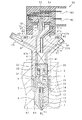
インジェクタは、図示しないコモンレール(蓄圧容器)内に蓄えられた高圧燃料を、ディーゼル内燃機関の気筒内に形成された燃焼室E1に噴射するものであり、開弁時に燃料を噴射するノズル1、電力供給されて駆動する電動アクチュエータ2、電動アクチュエータ2により駆動されてノズル1の背圧を制御する背圧制御機構3を備えている。
The injector is for injecting high pressure fuel stored in a common rail (pressure accumulating vessel) (not shown) into a combustion chamber E1 formed in a cylinder of a diesel internal combustion engine. An electric actuator 2 that is supplied and driven, and a back pressure control mechanism 3 that is driven by the electric actuator 2 to control the back pressure of the
ノズル1は、噴孔11が形成されたノズルボデー12、ノズルボデー12の弁座に接離して噴孔11を開閉するニードル13、ニードル13を閉弁向きに付勢するスプリング14を備えている。
The
電動アクチュエータ2には、ピエゾ素子を多数積層してなる積層体(ピエゾスタック)により構成されたピエゾアクチュエータが採用されており、ピエゾ素子への充電と放電とを切り替えることで伸長状態と縮小状態とが切り替えられる。これにより、ピエゾスタックはニードル13を作動させるアクチュエータとして機能する。なお、ピエゾアクチュエータに替えて、ステータ及びアーマチャにより構成された電磁アクチュエータを採用してもよい。
The electric actuator 2 employs a piezo actuator composed of a laminated body (piezo stack) formed by laminating a large number of piezo elements. By switching between charging and discharging of the piezo elements, an extension state and a contraction state are achieved. Is switched. Accordingly, the piezo stack functions as an actuator that operates the
背圧制御機構3のバルブボデー31内には、ピエゾアクチュエータ2の伸縮に追従して移動するピストン32、ピストン32をピエゾアクチュエータ2側に向かって付勢する皿ばね33、ピストン32に駆動される球状の弁体34が収納されている。
The
略円筒状のインジェクタボデー4は、その径方向中心部に、インジェクタ軸線方向(図1の上下方向)に延びる段付き円柱状の収納孔41が形成されており、この収納孔41にピエゾアクチュエータ2及び背圧制御機構3が収納されている。また、略円筒状のリテーナ5をインジェクタボデー4に螺合させることにより、インジェクタボデー4の端部にノズル1が保持されている。
The substantially
ノズルボデー12、インジェクタボデー4、及びバルブボデー31には、コモンレールから常に高圧燃料が供給される高圧通路6、及び図示しない燃料タンクに接続される低圧通路7が形成されている。また、これらのボデー12,4,31は金属製であり、焼入れ処理を施すことで高強度化されており、かつ、浸炭処理を施すことで表面が高硬度化されている。
The
これらのボデー12,4,31は、内燃機関のシリンダヘッドE2に形成されたボデー挿入孔E3に挿入配置されている。インジェクタボデー4にはクランプKの一端と係合する係合部42(押付面)が形成されており、クランプKの他端をシリンダヘッドE2にボルトで締め付けることにより、クランプKの一端が係合部42をボデー挿入孔E3に向けて押し付けることとなる。これにより、インジェクタはボデー挿入孔E3内に押し付けられた状態で固定される。
These
ニードル13における噴孔11側の外周面とノズルボデー12の内周面との間には、高圧通路6の一部となる高圧室15が形成されている。この高圧室15は、ニードル13が開弁方向に変位した際に噴孔11と連通する。ニードル13における反噴孔側(以下、「上側」と記載)には背圧室16が形成されている。この背圧室16には前述したスプリング14が配置されている。
A
バルブボデー31には、バルブボデー31内の高圧通路6とノズル1の背圧室16とを連通させる経路中に高圧シート面35が形成され、バルブボデー31内の低圧通路7とノズル1の背圧室16とを連通させる経路中に低圧シート面36が形成されている。そして、高圧シート面35と低圧シート面36との間に前述した弁体34が配置されている。
The
略円柱形状であるインジェクタボデー4の外周面には、図示しない高圧配管と接続される高圧ポート43(高圧配管接続部)、及び図示しない低圧配管と接続される低圧ポート44(低圧配管接続部)が形成されている。そして、コモンレールから高圧配管を通じて高圧ポート43に供給される燃料は、円筒状インジェクタボデー4の外周面側から供給される。インジェクタに供給された燃料は、高圧通路6を通じて高圧室15及び背圧室16へ流入する。
A high-pressure port 43 (high-pressure pipe connection portion) connected to a high-pressure pipe (not shown) and a low-pressure port 44 (low-pressure pipe connection portion) connected to a low-pressure pipe (not shown) are provided on the outer peripheral surface of the
高圧通路6には、インジェクタボデー4の上側に分岐する分岐通路6aが形成されている。この分岐通路6aにより、高圧通路6内の燃料は後述する燃圧センサ50に導入される。
The high-
インジェクタボデー4の上部にはコネクタ60が取り付けられている。コネクタ60の端子(駆動用コネクタ端子62)に外部から供給された電力は、リード線21を介してピエゾアクチュエータ2に供給され、これによりピエゾアクチュエータ2は伸長し、電力供給を停止すると縮小する。
A
上記構成において、ピエゾアクチュエータ2が縮小した状態では、図1に示すように弁体34が低圧シート面36に接して背圧室16は高圧通路6と接続され、背圧室16には高圧の燃料圧が導入される。そして、この背圧室16内の燃料圧とスプリング14とによってニードル13が閉弁向きに付勢されて噴孔11が閉じられている。
In the above configuration, when the piezo actuator 2 is contracted, the
一方、ピエゾアクチュエータ2に電圧が印加されてピエゾアクチュエータ2が伸長した状態では、弁体34が高圧シート面35に接して背圧室16は低圧通路7と接続され、背圧室16内は低圧になる。そして、高圧室15内の燃料圧によってニードル13が開弁向きに付勢されて噴孔11が開かれ、この噴孔11から燃焼室E1へ燃料が噴射される。
On the other hand, when a voltage is applied to the piezo actuator 2 and the piezo actuator 2 is extended, the
ここで、噴孔11からの燃料噴射に伴い高圧通路6内の高圧燃料の圧力は変動する。この圧力変動を検出する燃圧センサ50が、インジェクタボデー4に取り付けられている。燃圧センサ50により検出された圧力変動波形中において、噴孔11からの噴射開始に伴い燃圧が下降を開始した時期を検出することで、実際の噴射開始時期を検出することができる。また、噴射終了に伴い燃圧が上昇を開始した時期を検出することで、実際の噴射終了時期を検出することができる。また、これらの噴射開始時期及び噴射終了時期に加え、噴射に伴い生じた燃圧下降量の最大値を検出することで、噴射量を検出することができる。
Here, the pressure of the high-pressure fuel in the high-
次に、燃圧センサ50の単体構造、及び燃圧センサ50のインジェクタボデー4への取付構造について、図2を用いて説明する。
Next, the single-piece | unit structure of the
燃圧センサ50は、分岐通路6a内の高圧燃料の圧力を受けて弾性変形するステム51(起歪体)と、ステム51にて生じた歪の大きさを電気信号に変換して圧力検出値として出力する歪ゲージ(センサ素子)52と、を備えて構成されている。
The
ステム51は、高圧燃料を内部に導入する流入口51aが一端に形成された円筒形状の円筒部51bと、円筒部51bの他端を閉塞する円板形状のダイヤフラム部51cとを備えて構成されている。流入口51aから円筒部51b内に流入した高圧燃料の圧力を、円筒部51bの内面及びダイヤフラム部51cで受け、これによりステム51全体が弾性変形することとなる。
The
ステム51は金属製であり、その金属材料には、超高圧を受けることから高強度、高硬度であること、及び、熱膨張による変形が少なく歪ゲージ52への影響が少ない(つまり低熱膨張係数である)こと、が求められ、具体的には、Fe,Ni,CoまたはFe,Niを主体とし、析出強化材料としてTi,Nb,Al又はTi,Nbが加えられた材料を選定し、プレス、切削や冷間鍛造等により形成できる。また、C,Si,Mn,P,S等が加えられた材料を選定してもよい。
The
略円柱状に形成されたインジェクタボデー4の円柱端部には、高圧ポート43及び低圧ポート44の取付位置から上側に突出する円柱形状のセンサ取付部45が設けられている(図1参照)。センサ取付部45の上端面45aには、ステム51の円筒部51bが挿入される凹部46が形成されている。凹部46の内周面には雌螺子部46a(ボデー側螺子部)が形成され、円筒部51bの外周面には雄螺子部51d(センサ側螺子部)が形成されている。そして、インジェクタボデー4の雌螺子部46aにステム51の雄螺子部51dを螺子締結することで、燃圧センサ50はインジェクタボデー4に取り付けられる。
A cylindrical
円筒部51bのうち流入口51a周りに位置する円筒端面にはセンサ側シール面51eが形成され、凹部46の底面にはボデー側シール面46bが形成されている。両シール面51e,46bは、ステム51の軸方向(図2の上下方向)に対して垂直に拡がる向きの面であり、流入口51a周りに円環状に延びる形状である。
A sensor-
そして、センサ側シール面51eをボデー側シール面46bに押し付けて密着させることで、インジェクタボデー4とステム51との間をメタルタッチシールするよう構成されている。両シール面51e,46bを押し付ける力(軸力)は、インジェクタボデー4へのステム51の螺子締結により生じている。つまり、インジェクタボデー4へのステム51の取り付けと軸力発生とを同時に行う。
The sensor-
歪ゲージ52は、ダイヤフラム部51cに取り付けられている。より詳細には、歪ゲージ52は、ダイヤフラム部51c上に配置された状態でガラス部材52bにより封止(焼付け)して固定されている。したがって、円筒部51b内に流入した高圧燃料の圧力によりステム51が拡大するよう弾性変形した時、ダイヤフラム部51cに生じた歪の大きさ(弾性変形量)を歪ゲージ52が検出することとなる。
The
ステム51には、円板形状の金属製プレート53が取り付けられており、このプレート53上には、後に詳述するモールドIC54が固定支持されている。
A disc-shaped
モールドIC54は、ワイヤボンドWにより歪ゲージ52と電気接続されており、電子部品54a及びセンサ端子54bを、モールド樹脂54mで封止して構成されている。電子部品54aは、歪ゲージ52から出力される検出信号を増幅する増幅回路や、検出信号に重畳するノイズを除去するフィルタリング回路、歪ゲージ52に電圧印加する回路等を構成する。
The
なお、電圧印加回路から電圧印加された歪ゲージ52は、ダイヤフラム部51cにて生じた歪の大きさに応じて抵抗値が変化するブリッジ回路を構成している。これにより、ダイヤフラム部51cの歪に応じてブリッジ回路の出力電圧が変化し、当該出力電圧が高圧燃料の圧力検出値としてモールドIC54の増幅回路に出力される。増幅回路は、歪ゲージ52(ブリッジ回路)から出力される圧力検出値を増幅し、増幅した信号をセンサ端子54bから出力する。
Note that the
モールド樹脂54mは、ステム51の円筒部51bの外周面に沿って環状に延びる円筒形状に形成されている。モールド樹脂54mの外周面からは複数のセンサ端子54bが延出している。これらのセンサ端子54bは、モールドIC54内部にて電子部品54aと電気接続されており、燃圧センサの検出信号を出力する端子、電源を供給する端子、接地用端子等として機能するものである。
The
プレート53の外周端部にはケース56が取り付けられている。そして、ケース56及びプレート53の内部に、ステム51の円筒部51bのうち雄螺子部51dを除く部分、歪ゲージ52、及びモールドIC54が収容されている。これにより、金属製のケース56及びプレート53が外部ノイズを遮断して、歪ゲージ52及びモールドIC54を保護する。なお、ケース56の外周面には開口部56aが形成されており、センサ端子54bは開口部56aを通じてケース56の内部から外部へと延出している。
A
先述したコネクタ60のハウジング61には、駆動用コネクタ端子62とともにセンサ用コネクタ端子63が保持されている。センサ用コネクタ端子63とセンサ端子54bとは、後述する電極71,72,73を介してレーザ溶接等により電気接続される。コネクタ60には、図示しないエンジンECU等の外部機器と接続する外部ハーネスのコネクタが接続される。これにより、外部ハーネスを介して、モールドIC54から出力される圧力検出信号がエンジンECUに入力される。
The
ここで、ステム51を回転させてステム51をインジェクタボデー4へ螺子締結するにあたり、この螺子締結が完了した時点において、ステム51の回転位置は特定の位置に定まらない。このことは、モールドICのセンサ端子54b〜54eも、ステム51の螺子締結完了時点においてその回転位置が不特定となることを意味する。
Here, when the
そこで、センサ端子54bの各々に接続されてステム51とともに回転する電極72,73の各々には、ステム51の回転中心周りに円環状に延びる形状の、円環状接続部72a,73aが形成されている。円環状接続部72a,73aは、ステム51の螺子締結が完了した後に、複数のコネクタ端子63の各々と電気接続される。これにより、回転位置が不特定となるセンサ端子54bと、インジェクタボデー4の所定位置に配置されたコネクタ端子63とを、容易に電気接続できる。
Therefore, each of the
なお、電極71のうちコネクタ端子63と電気接続される接続部71aは、ステム51の回転中心に位置するため、ステム51の回転位置に拘わらず接続部71aの回転位置は特定される。また、複数の電極71〜73はモールド樹脂70mによりモールドされて一体化されており、このようにモールドされた状態でケース56の上面に載せられている。また、コネクタ端子63には接続部71a,72a,73aに向けて突出する溶接部63aが形成されており、レーザ溶接する際のレーザエネルギを溶接部63aに集中させる。
In addition, since the connection part 71a electrically connected with the
図1の説明に戻り、電動アクチュエータ2にはリード線21が接続されている。このリード線21は、保持部材21a,21bに保持された状態で、ボデー4に形成されたリード線挿入孔47a,47bに挿入配置されている。保持部材21a,21bは、リード線21の被覆が磨耗するのを抑制するために、金属よりも硬度が低い材料(例えばナイロン等の樹脂)よりなる。また、保持部材21a,21bは、リード線21よりも剛性が高くなるように形状や厚さ等が設定されている。
Returning to the description of FIG. 1, a
センサ取付部45の外周面45bには、リード線21がリード線挿入孔47a,47bからボデー4の外に取り出される取出口47cが形成されている。リード線21のうち取出口47cの外に取り出されている部分は、駆動用コネクタ端子62に電気接続されている。
An
リード線挿入孔47a,47bは、ボデー4の中心軸方向(図1の上下方向)に直線的に延びる第1挿入孔47aと、第1挿入孔47aの上端部からセンサ取付部45の外周面45bに位置する取出口47cに向けて直線的に延びる第2挿入孔47bと、を有する。第1挿入孔47a及び第2挿入孔47bは断面円形の孔であり、第1挿入孔47aの軸中心は、ボデー4の軸中心と一致する。なお、ステム51の軸中心もボデー4の軸中心と一致する。
The lead
また、先述した保持部材21a,21bは、第1挿入孔47aに配置される保持部材21aと、第2挿入孔47bに配置される保持部材21bとに分割して形成されている。
Further, the above-described
次に、燃圧センサ50等のインジェクタボデー4への取り付け手順について説明する。
Next, a procedure for attaching the
先ず、ステム51及び歪ゲージ52からなる燃圧センサ50に、プレート53、モールドIC54、ケース56、及びモールドされた状態の電極71〜73を組み付けて一体化し、センサアッシーAsを構成する。そして、センサアッシーAsをインジェクタボデー4に取り付ける。具体的には、ステム51の雄螺子部51dを、インジェクタボデー4の凹部46に形成された雌螺子部46aに締結させる。その後、電極71〜73とセンサ用コネクタ端子63とをレーザ溶接等により電気接続する。
First, the
また、ボデー4の収納孔41に電動アクチュエータ2を挿入させるとともに、電動アクチュエータ2のリード線21を、保持部材21aに保持させた状態で、収納孔41の側からリード線挿入孔47a,47bに挿入する。そして、リード線21のうち取出口47cから取り出されている部分と、駆動用コネクタ端子62とを、レーザ溶接等により電気接続する。
In addition, the electric actuator 2 is inserted into the
その後、コネクタ端子62,63及びセンサアッシーAsを、インジェクタボデー4に取り付けた状態のままモールド樹脂でモールド成形する。このモールド樹脂は、先述したコネクタハウジング61となる。また、リード線21のうち取出口47cの外に取り出されている部分であってコネクタ端子62と溶接される箇所、及び燃圧センサ50は、前記モールド樹脂により、センサ取付部45とともに封止される。以上により、燃圧センサ50等のインジェクタボデー4への取り付け、及び内部電気接続が完了する。
Thereafter, the
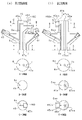
次に、インジェクタボデー4に形成された高圧通路6、低圧通路7、第1挿入孔47a及び第2挿入孔47b(リード線挿入孔)の位置関係について、図3を用いて説明する。なお、これらの高圧通路6、低圧通路7、第1挿入孔47a及び第2挿入孔47b(リード線挿入孔)は、インジェクタボデー4にドリル加工することで形成されている。
Next, the positional relationship among the
図3(a)は本実施形態にインジェクタボデー4単体を示す。図3(b)は、特許文献1記載のボデーに燃圧センサ50xを搭載した場合について本発明者らが検討した、第1比較例としてのボデー4x単体を示す。また、図3では断面を示すハッチングを省略しており、図3の最上段に記載の断面図は図1と同様の断面図であり、その断面図の下に、A−A断面図、B−B断面図及びC矢視図を順に記載している。なお、図3(b)中の部材のうち図3(a)中の部材と対応するものについては、符号の末尾にxを付加してその説明を援用する。
FIG. 3A shows the
図3(a)に示すように、本実施形態のボデー4では、取出口47cをセンサ取付部45の外周面45bに形成するとともに、取出口47cを凹部46の下方に位置させている。詳細には、取出口47cのうち最も上方に位置する部分P1を、凹部46のうち最も下方に位置する部分P2(図3(a)の例ではボデー側シール面46bの部分)よりも下側に位置させている。また、本実施形態のボデー4では、第1挿入孔47aを凹部46の下方に位置させている。詳細には、第1挿入孔47aの端部であって、第2挿入孔47bと接続する部分P3を、凹部46のうち最も下方に位置する部分P2よりも下側に位置させている。
As shown in FIG. 3A, in the
以上により、本実施形態によれば、取出口47cをステム51(凹部46)の下側に位置させることで、取出口47cへ向けて延びる第2挿入孔47b及び第1挿入孔47aを、ステム51の搭載スペースより下側に位置させている。よって、リード線挿入孔47a,47bと凹部46(ステム51)とがボデー4の径方向において隣り合うことを回避できるので(B−B断面図及びC矢視図参照)、ボデー4の径方向への大型化を抑制しつつステム51の搭載自由度を向上できる。
As described above, according to the present embodiment, the
これに対し、図3(b)に示す第1比較例のボデー4xでは、リード線挿入孔47axをボデー4xの中心軸方向(図3の上下方向)に延びる形状に形成して、取出口47cxをセンサ取付部45xの上端面に形成している。そのため、リード線挿入孔47axと凹部46xとがボデー4xの径方向に並ぶので(B−B断面図及びC矢視図参照)、ボデー4xの断面積のうち網点を付した部分には凹部46xを形成することができず、その分、ステムの搭載自由度が制約される。その結果、網点部分を除く面積で凹部46xの搭載面積を確保できるようにするために、センサ取付部45xの外径寸法を大きくすることを要する。なお、図3(b)中の一点鎖線45bは、本実施形態のセンサ取付部45の外周面を示す。
On the other hand, in the
さらに本実施形態によれば、以下に列挙する効果も発揮される。 Furthermore, according to this embodiment, the effects listed below are also exhibited.
・リード線21のうち取出口47cの外に取り出されている部分及びセンサアッシーAsを、センサ取付部45とともに樹脂モールドするので、リード線21の取り出し部分及びセンサアッシーAsを絶縁状態でセンサ取付部45に固定することを容易に実現でき、好適である。
The portion of the
・樹脂モールドされるセンサ取付部45を、高圧ポート43及び低圧ポート44よりも上側に突出する形状にするので、両ポート43,44の一部とともに樹脂モールドする場合に比べてコネクタハウジング61の体格を小さくでき、ひいてはインジェクタの小型化に寄与できる。そして、このようにセンサ取付部45を上側に突出した形状にしたことで、ステム51及び取出口47cを配置するスペースは限られた小さいスペースとなる。よって、「ボデー4の大型化を抑制しつつステム51の搭載自由度を向上できる」といった上記効果が好適に発揮されることとなる。
Since the
・ボデー4のうち係合部42よりも上側にステム51を配置するので、ボデーのうち歪が大きくなる部分(つまり、シリンダヘッドE2に支持される部分と係合部42との間の部分)から外れた箇所にステム51が位置することとなる。よって、ボデー4に生じる歪の影響を燃圧センサが受けることを抑制でき、燃圧の検出精度を向上できる。
-Since the
・ステム51を挿入配置させる凹部46を、センサ取付部45の上端面45aから凹むように形成するので、上端面45aから筒状に延びる形状にセンサ取付部を形成する場合に比べて、センサ取付部45の大型化を抑制できる。そして、このようにセンサ取付部45から凹む凹部46にステム51を取り付ける構成にしたことで、ステム51を配置するスペースは限られた小さいスペースとなる。よって、「ボデー4の大型化を抑制しつつステム51の搭載自由度を向上できる」といった上記効果が好適に発揮されることとなる。
Since the
・センサ用コネクタ端子63及び駆動用コネクタ端子62を共通のコネクタハウジング61に保持させ、コネクタハウジング61及び両端子62,63により1つのコネクタを構成する。そのため、コネクタの数を増やすことなくインジェクタに燃圧センサ50を搭載できる。
The
(第2実施形態)
上記第1実施形態では、センサ取付部45の上端面45aに凹部46を形成し、センサ取付部45の上方からステム51を取り付けている。これに対し図4(a)に示す本実施形態では、センサ取付部45の外周面45bに凹部460を形成し、センサ取付部45の径方向からステム51を取り付けている。
(Second Embodiment)
In the first embodiment, the
本実施形態においても上記第1実施形態と同様にして、取出口47cを凹部460の下方に位置させている。詳細には、取出口47cのうち最も上方に位置する部分P1を、凹部46のうち最も下方に位置する部分P2よりも下側に位置させている。また、第1挿入孔47aを凹部460の下方に位置させている。詳細には、第1挿入孔47aの端部であって、第2挿入孔47bと接続する部分P3を、凹部460のうち最も下方に位置する部分P2よりも下側に位置させている。
Also in the present embodiment, the
以上により、本実施形態によっても、リード線挿入孔47a,47bとステム51とがボデー4の径方向において隣り合うことを回避できるので(B−B断面図及びC−C断面図参照)、ボデー4の径方向への大型化を抑制しつつステム51の搭載自由度を向上できる。
As described above, according to the present embodiment, the lead
これに対し、図4(b)に示す第2比較例のボデー4xでは、リード線挿入孔47axを上下方向に延びる形状に形成して、取出口47cxをセンサ取付部45xの上端面に形成している。そのため、リード線挿入孔47axと凹部46xとがボデー4xの径方向に並ぶので(B−B断面図及びC−C断面図参照)、ボデー4xの断面積のうち網点を付した部分には凹部460xを形成することができず、その分、ステムの搭載自由度が制約される。その結果、網点部分を除く面積で凹部460xの搭載面積を確保できるようにするために、センサ取付部45xの外周面から筒状に突出する突出部45cxを形成し、その突出部45cxに凹部460xを形成することを要する。よって、センサ取付部45xが径方向に大型化する。
On the other hand, in the
(第3実施形態)
上記第1実施形態では、取出口47cのうち最も上方に位置する部分P1を、凹部46のうち最も下方に位置する部分P2(ボデー側シール面46b)よりも下側に位置させている。これに対し、図5に示す本実施形態では、取出口47cの最上方部分P1が凹部46の最下方部分P2よりも上側に位置するものの、取出口47cのうち最も下方に位置する部分P4を、凹部46の最下方部分P2よりも下側に位置させている。
(Third embodiment)
In the first embodiment, the uppermost portion P1 of the
また、第1挿入孔47aの端部であって、第2挿入孔47bと接続する部分P3については、上記第1実施形態と同様にして、凹部46の最下方部分P2よりも下側に位置させている。
Further, the end portion of the
本実施形態によれば、ボデー4の径方向において第2挿入孔47bの一部が凹部46と隣り合うものの、軸方向において凹部46の全体が第2挿入孔47bと隣り合うことは回避されるので、図3(b)に示す第1比較例に比べれば、ボデー4の径方向への大型化を抑制しつつステム51の搭載自由度を向上できる。
According to the present embodiment, although a part of the
(第4実施形態)
上記第1実施形態では、ボデー4の外周面に高圧ポート43を設け、ボデー4の側方から高圧燃料を供給するインジェクタに本発明を適用している。そして、ステム51を挿入配置する凹部46を、高圧ポート43との干渉を避けるためボデー4(センサ取付部45)の上端面45aに形成している。
(Fourth embodiment)
In the first embodiment, the
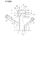
これに対し、図6に示す本実施形態では、ボデー4の上端面に高圧ポート43を設け、ボデー4の上方から高圧燃料を供給するインジェクタに本発明を適用している。そして、ステム51を挿入配置する凹部46を、高圧ポート43との干渉を避けるためボデー4の外周面に形成している。
In contrast, in the present embodiment shown in FIG. 6, the
なお、高圧ポート43には、その外周面に図示しない高圧配管が取り付けられるのに対し、低圧ポート44には、図示しない低圧配管が挿入される低圧配管挿入穴44a(低圧配管接続部)が形成されている。そして、低圧配管挿入穴44aは、ボデー4の外周面のうち取出口47cの下方に設けられている。
The high-
本実施形態においても上記第1実施形態と同様にして、取出口47cを凹部46の下方に位置させている。つまり、第1挿入孔47aを凹部46の下方に位置させている。そのため、リード線挿入孔47a,47bと凹部46とがボデー4の径方向において隣り合うことを回避できるので、ボデー4の径方向への大型化を抑制しつつステム51の搭載自由度を向上できる。
Also in the present embodiment, the
(第5実施形態)
上記第4実施形態では、ボデー4の外周面に低圧配管挿入穴44a、取出口47c及び凹部46を配置するにあたり、取出口47cを、凹部46の下方に位置させるとともに、低圧配管挿入穴44aの上方に位置させている。これに対し、図7に示す本実施形態では、取出口47cを、凹部46の下方かつ低圧配管挿入穴44aの下方に位置させている。
(Fifth embodiment)
In the fourth embodiment, when the low pressure
これによれば、上記第4実施形態と同様にして取出口47cを凹部46の下方に位置させるため、リード線挿入孔47a,47bと凹部46とがボデー4の径方向において隣り合うことを回避でき、ボデー4の径方向への大型化を抑制しつつステム51の搭載自由度を向上できる。
According to this, since the
さらに、本実施形態では、取出口47cを低圧配管挿入穴44aの下方に位置させるため、リード線挿入孔47a,47bと低圧配管挿入穴44aとがボデー4の径方向において隣り合うことを回避できる。よって、ボデー4の径方向への大型化を抑制しつつステム51の搭載自由度を向上できる。
Further, in the present embodiment, since the
例えば、図6及び図7の比較にて明らかなように、取出口47cを低圧配管挿入穴44aの上方に位置させる図6のボデー4に比べて、取出口47cを低圧配管挿入穴44aの下方に位置させる図7のボデー4は径方向に小型化できる。但し、図6のボデー4によれば取出口47cを凹部46の近くに配置できるので、センサ用コネクタ端子63及び駆動用コネクタ端子62を共通のコネクタハウジング61に保持させて1つのコネクタを構成することを、図7のボデー4に比べて容易に実現できる。
For example, as apparent from the comparison between FIGS. 6 and 7, the
(他の実施形態)
本発明は上記実施形態の記載内容に限定されず、以下のように変更して実施してもよい。また、各実施形態の特徴的構成をそれぞれ任意に組み合わせるようにしてもよい。
(Other embodiments)
The present invention is not limited to the description of the above embodiment, and may be modified as follows. Moreover, you may make it combine the characteristic structure of each embodiment arbitrarily, respectively.
・上記第1実施形態において、ステム51を螺子締結することで、センサアッシーAsのインジェクタボデー4への組み付けと、両シール面51e,46bの軸力発生とを同時に行うよう構成しているが、センサアッシーAsをインジェクタボデー4へ組み付けるための螺子部と、軸力発生のための螺子部とを別々に備えるよう構成してもよい。
In the first embodiment, the
・上記各実施形態では、ステム51に螺子部51dを形成してステム51をボデー4に螺子締結させている。これに対し、例えばプレート53やケース56に螺子部を形成してボデー4に螺子締結させるよう構成してもよい。
In each of the above embodiments, the
・上記各実施形態では、ステム51の歪量を検出するセンサ素子として歪ゲージ52を採用しているが、圧電素子等、他のセンサ素子を採用してもよい。
In each of the above embodiments, the
・上記各実施形態では、ディーゼルエンジンのインジェクタに本発明を適用しているが、ガソリンエンジン、特に、燃焼室E1に燃料を直接噴射する直噴式のガソリンエンジンに本発明を適用してもよい。 In each of the above embodiments, the present invention is applied to an injector of a diesel engine. However, the present invention may be applied to a gasoline engine, particularly, a direct injection gasoline engine that directly injects fuel into the combustion chamber E1.
2…電動アクチュエータ、4…インジェクタボデー(ボデー)、13…ニードル、21…リード線、42…係合部(押付面)、43…高圧ポート、44…低圧ポート、45…センサ取付部、46,460…凹部、47a…第1挿入孔(リード線挿入孔)、47b…第2挿入孔(リード線挿入孔)、47c…取出口、50…燃圧センサ、51…ステム(起歪体)、52…歪ゲージ(センサ素子)、61…コネクタハウジング、62…駆動用コネクタ端子、63…センサ用コネクタ端子、E3…ボデー挿入孔。
DESCRIPTION OF SYMBOLS 2 ... Electric actuator, 4 ... Injector body (body), 13 ... Needle, 21 ... Lead wire, 42 ... Engagement part (pressing surface), 43 ... High pressure port, 44 ... Low pressure port, 45 ... Sensor attachment part, 46, 460: recess, 47a ... first insertion hole (lead wire insertion hole), 47b ... second insertion hole (lead wire insertion hole), 47c ... outlet, 50 ... fuel pressure sensor, 51 ... stem (distortion body), 52 Strain gauge (sensor element) 61
Claims (7)
前記噴孔へ高圧燃料を流通させる高圧通路を内部に形成するボデーと、
前記ボデー内部に収容されて前記噴孔を開閉するニードルと、
前記ニードルを開閉作動させるための電動アクチュエータと、
前記ボデーに形成されたリード線挿入孔に配置され、前記電動アクチュエータに電力供給するリード線と、
前記ボデーに取り付けられて前記高圧燃料の圧力を検出する燃圧センサと、
を備え、
前記リード線が前記リード線挿入孔から前記ボデーの外に取り出される取出口を、前記燃圧センサよりも前記噴孔に近い側に位置させたことを特徴とする燃料噴射弁。 In a fuel injection valve mounted on an internal combustion engine and injecting fuel from a nozzle hole,
A body that internally forms a high-pressure passage through which high-pressure fuel flows to the nozzle hole;
A needle housed inside the body to open and close the nozzle hole;
An electric actuator for opening and closing the needle;
A lead wire disposed in a lead wire insertion hole formed in the body and supplying power to the electric actuator;
A fuel pressure sensor attached to the body for detecting the pressure of the high-pressure fuel;
With
A fuel injection valve characterized in that an outlet through which the lead wire is taken out of the body from the lead wire insertion hole is positioned closer to the injection hole than the fuel pressure sensor.
前記噴孔へ高圧燃料を流通させる高圧通路を内部に形成するボデーと、
前記ボデー内部に収容されて前記噴孔を開閉するニードルと、
前記ニードルを開閉作動させるための電動アクチュエータと、
前記ボデーに形成されたリード線挿入孔に配置され、前記電動アクチュエータに電力供給するリード線と、
前記ボデーに取り付けられて前記高圧燃料の圧力を検出する燃圧センサと、
を備え、
前記ボデーは、前記噴孔が先端に位置する略円柱の形状であり、
前記リード線が前記リード線挿入孔から前記ボデーの外に取り出される取出口は、前記ボデーの外周面に形成され、
前記リード線挿入孔は、前記ボデーの円柱中心軸方向に延びる第1挿入孔、及び前記第1挿入孔の端部から前記取出口に向けて延びる第2挿入孔を有し、
前記第1挿入孔の端部を、前記燃圧センサよりも前記噴孔に近い側に位置させたことを特徴とする燃料噴射弁。 In a fuel injection valve mounted on an internal combustion engine and injecting fuel from a nozzle hole,
A body that internally forms a high-pressure passage through which high-pressure fuel flows to the nozzle hole;
A needle housed inside the body to open and close the nozzle hole;
An electric actuator for opening and closing the needle;
A lead wire disposed in a lead wire insertion hole formed in the body and supplying power to the electric actuator;
A fuel pressure sensor attached to the body for detecting the pressure of the high-pressure fuel;
With
The body has a substantially cylindrical shape with the nozzle hole located at the tip,
The outlet through which the lead wire is taken out of the body from the lead wire insertion hole is formed on the outer peripheral surface of the body,
The lead wire insertion hole has a first insertion hole extending in a cylindrical central axis direction of the body, and a second insertion hole extending from an end of the first insertion hole toward the outlet.
A fuel injection valve characterized in that an end of the first insertion hole is positioned closer to the injection hole than the fuel pressure sensor.
前記ボデーの円柱端部には、前記高圧ポート及び前記低圧ポートよりも反噴孔側に突出する形状のセンサ取付部が設けられ、
前記センサ取付部には、前記燃圧センサが取り付けられるとともに前記取出口が形成され、
前記リード線のうち前記取出口の外に取り出されている部分及び前記燃圧センサは、前記センサ取付部とともに樹脂モールドされて封止されていることを特徴とする請求項1又は2に記載の燃料噴射弁。 The outer peripheral surface of the body having a substantially cylindrical shape is provided with a high pressure port to which the high pressure fuel is supplied and a low pressure port for discharging surplus fuel,
At the cylindrical end portion of the body, a sensor mounting portion is provided that protrudes more toward the counter-injection hole than the high pressure port and the low pressure port.
In the sensor mounting portion, the fuel pressure sensor is mounted and the outlet is formed,
The fuel according to claim 1 or 2, wherein a portion of the lead wire taken out of the outlet and the fuel pressure sensor are resin-molded and sealed together with the sensor mounting portion. Injection valve.
前記ボデーには、前記クランプが当接して押し付けられる押付面が形成されており、
前記センサ取付部は、前記押付面よりも反噴孔側に位置することを特徴とする請求項3に記載の燃料噴射弁。 The body is arranged to be inserted into a body insertion hole formed in a cylinder head of the internal combustion engine, and is configured to be pressed against the body insertion hole by a clamp,
The body is formed with a pressing surface against which the clamp abuts and is pressed,
The fuel injection valve according to claim 3, wherein the sensor mounting portion is located on a side opposite to the injection hole from the pressing surface.
前記ボデーには、前記クランプが当接して押し付けられる押付面が形成されており、
前記ボデーの反噴孔側端部には、前記押付面よりも反噴孔側に突出する形状のセンサ取付部が設けられ、
前記センサ取付部には、前記燃圧センサが取り付けられることを特徴とする請求項1又は2に記載の燃料噴射弁。 The body is arranged to be inserted into a body insertion hole formed in a cylinder head of the internal combustion engine, and is configured to be pressed against the body insertion hole by a clamp,
The body is formed with a pressing surface against which the clamp abuts and is pressed,
At the end of the body on the side opposite to the injection hole, a sensor mounting portion is provided that protrudes toward the side opposite to the injection hole from the pressing surface.
The fuel injection valve according to claim 1, wherein the fuel pressure sensor is attached to the sensor attachment portion.
略円柱状に形成された前記センサ取付部には、前記センサ取付部の外周面又は円柱端面から凹む凹部が形成されており、
前記凹部に前記起歪体を挿入配置させることを特徴とする請求項3〜5のいずれか1つに記載の燃料噴射弁。 The fuel pressure sensor is attached to the body and elastically deforms upon receiving the pressure of the high-pressure fuel, and converts the magnitude of strain generated in the strain generating body attached to the strain generating body into an electric signal. And a sensor element to be configured,
The sensor mounting portion formed in a substantially cylindrical shape has a concave portion that is recessed from the outer peripheral surface of the sensor mounting portion or the end surface of the cylinder.
The fuel injection valve according to claim 3, wherein the strain body is inserted and disposed in the recess.
前記燃圧センサと電気接続されるセンサ用コネクタ端子と、
前記リード線と電気接続される駆動用コネクタ端子と、
を備え、
前記センサ用コネクタ端子及び前記駆動用コネクタ端子を前記コネクタハウジングに保持させることで、前記センサ用コネクタ端子及び前記駆動用コネクタ端子を共通のコネクタに構成したことを特徴とする請求項1〜6のいずれか1つに記載の燃料噴射弁。 A connector housing attached to the body and connected to an external harness by a connector;
A sensor connector terminal electrically connected to the fuel pressure sensor;
A drive connector terminal electrically connected to the lead wire;
With
7. The sensor connector terminal and the drive connector terminal are configured to be a common connector by holding the sensor connector terminal and the drive connector terminal in the connector housing. The fuel injection valve according to any one of the above.
Priority Applications (3)
| Application Number | Priority Date | Filing Date | Title |
|---|---|---|---|
| JP2009090761A JP5120318B2 (en) | 2009-04-03 | 2009-04-03 | Fuel injection valve |
| DE102010016302.3A DE102010016302B4 (en) | 2009-04-03 | 2010-04-01 | Injection device mounted in an internal combustion engine |
| US12/753,360 US8342155B2 (en) | 2009-04-03 | 2010-04-02 | Injector |
Applications Claiming Priority (1)
| Application Number | Priority Date | Filing Date | Title |
|---|---|---|---|
| JP2009090761A JP5120318B2 (en) | 2009-04-03 | 2009-04-03 | Fuel injection valve |
Publications (2)
| Publication Number | Publication Date |
|---|---|
| JP2010242580A JP2010242580A (en) | 2010-10-28 |
| JP5120318B2 true JP5120318B2 (en) | 2013-01-16 |
Family
ID=42751237
Family Applications (1)
| Application Number | Title | Priority Date | Filing Date |
|---|---|---|---|
| JP2009090761A Active JP5120318B2 (en) | 2009-04-03 | 2009-04-03 | Fuel injection valve |
Country Status (3)
| Country | Link |
|---|---|
| US (1) | US8342155B2 (en) |
| JP (1) | JP5120318B2 (en) |
| DE (1) | DE102010016302B4 (en) |
Families Citing this family (4)
| Publication number | Priority date | Publication date | Assignee | Title |
|---|---|---|---|---|
| JP5079650B2 (en) * | 2007-11-02 | 2012-11-21 | 株式会社デンソー | Fuel injection valve and fuel injection device |
| JP5383132B2 (en) * | 2008-03-28 | 2014-01-08 | 株式会社デンソー | Fuel pressure sensor mounting structure, fuel pressure detection system, fuel injection device, pressure detection device and pressure accumulation fuel injection device system used therefor |
| JP5154495B2 (en) * | 2009-04-03 | 2013-02-27 | 株式会社日本自動車部品総合研究所 | Fuel injection valve and internal electric connection method of fuel injection valve |
| JP5262948B2 (en) | 2009-04-20 | 2013-08-14 | 株式会社デンソー | Fuel injection valve |
Family Cites Families (17)
| Publication number | Priority date | Publication date | Assignee | Title |
|---|---|---|---|---|
| JPS575526A (en) * | 1980-06-11 | 1982-01-12 | Diesel Kiki Co Ltd | Method of detecting injection flow in fuel injection valve |
| JP3692669B2 (en) * | 1996-12-06 | 2005-09-07 | 日産自動車株式会社 | Piezoelectric fuel injection valve |
| JP3444120B2 (en) * | 1996-12-18 | 2003-09-08 | 日産自動車株式会社 | Fuel injection device |
| JP2005172761A (en) * | 2003-12-15 | 2005-06-30 | Denso Corp | Pressure sensor |
| JP2006226137A (en) * | 2005-02-15 | 2006-08-31 | Denso Corp | Fuel injection device |
| JP4506709B2 (en) * | 2006-04-05 | 2010-07-21 | 株式会社デンソー | Injector |
| JP4840288B2 (en) * | 2006-11-14 | 2011-12-21 | 株式会社デンソー | Fuel injection apparatus and adjustment method thereof |
| US7552717B2 (en) | 2007-08-07 | 2009-06-30 | Delphi Technologies, Inc. | Fuel injector and method for controlling fuel injectors |
| JP4424395B2 (en) * | 2007-08-31 | 2010-03-03 | 株式会社デンソー | Fuel injection control device for internal combustion engine |
| JP5262933B2 (en) * | 2009-04-03 | 2013-08-14 | 株式会社デンソー | Fuel injection device |
| JP5154495B2 (en) * | 2009-04-03 | 2013-02-27 | 株式会社日本自動車部品総合研究所 | Fuel injection valve and internal electric connection method of fuel injection valve |
| JP5104806B2 (en) * | 2009-04-03 | 2012-12-19 | 株式会社デンソー | Fuel injection valve and fuel injection valve manufacturing method |
| JP5278120B2 (en) * | 2009-04-03 | 2013-09-04 | 株式会社デンソー | Fuel injection device |
| JP5120316B2 (en) * | 2009-04-03 | 2013-01-16 | 株式会社デンソー | Fuel injection device |
| JP2010249061A (en) * | 2009-04-17 | 2010-11-04 | Denso Corp | Fuel injection valve |
| JP5262948B2 (en) * | 2009-04-20 | 2013-08-14 | 株式会社デンソー | Fuel injection valve |
| JP4735735B2 (en) * | 2009-04-21 | 2011-07-27 | 株式会社デンソー | Injector |
-
2009
- 2009-04-03 JP JP2009090761A patent/JP5120318B2/en active Active
-
2010
- 2010-04-01 DE DE102010016302.3A patent/DE102010016302B4/en active Active
- 2010-04-02 US US12/753,360 patent/US8342155B2/en active Active
Also Published As
| Publication number | Publication date |
|---|---|
| US20100252003A1 (en) | 2010-10-07 |
| JP2010242580A (en) | 2010-10-28 |
| DE102010016302A1 (en) | 2010-10-21 |
| US8342155B2 (en) | 2013-01-01 |
| DE102010016302B4 (en) | 2022-07-07 |
Similar Documents
| Publication | Publication Date | Title |
|---|---|---|
| JP5265439B2 (en) | Fuel injection valve | |
| JP5169951B2 (en) | Fuel injection valve | |
| JP5044368B2 (en) | Fuel injection valve | |
| JP5220674B2 (en) | Fuel injection valve and internal electric connection method of fuel injection valve | |
| JP4959509B2 (en) | Fuel injection valve | |
| JP5169950B2 (en) | Fuel injection valve | |
| JP5104806B2 (en) | Fuel injection valve and fuel injection valve manufacturing method | |
| JP5064341B2 (en) | Fuel injection valve and fuel injection device | |
| JP4954848B2 (en) | Fuel injection valve | |
| JP5079643B2 (en) | Fuel injection valve and fuel injection device | |
| US20100263629A1 (en) | Fuel injection valve | |
| JP5154495B2 (en) | Fuel injection valve and internal electric connection method of fuel injection valve | |
| JP2009222051A (en) | Fuel injection valve and fuel injection device | |
| JP5120318B2 (en) | Fuel injection valve | |
| JP2010255427A (en) | Fuel injection valve | |
| US8474734B2 (en) | Injector | |
| JP5223765B2 (en) | Fuel injection valve | |
| JP5240019B2 (en) | Fuel injection valve and internal electric connection method of fuel injection valve | |
| JP2011047280A (en) | Fuel injection valve | |
| JP5195602B2 (en) | Fuel injection valve |
Legal Events
| Date | Code | Title | Description |
|---|---|---|---|
| A621 | Written request for application examination |
Free format text: JAPANESE INTERMEDIATE CODE: A621 Effective date: 20110630 |
|
| A977 | Report on retrieval |
Free format text: JAPANESE INTERMEDIATE CODE: A971007 Effective date: 20120918 |
|
| TRDD | Decision of grant or rejection written | ||
| A01 | Written decision to grant a patent or to grant a registration (utility model) |
Free format text: JAPANESE INTERMEDIATE CODE: A01 Effective date: 20120925 |
|
| A01 | Written decision to grant a patent or to grant a registration (utility model) |
Free format text: JAPANESE INTERMEDIATE CODE: A01 |
|
| A61 | First payment of annual fees (during grant procedure) |
Free format text: JAPANESE INTERMEDIATE CODE: A61 Effective date: 20121008 |
|
| FPAY | Renewal fee payment (event date is renewal date of database) |
Free format text: PAYMENT UNTIL: 20151102 Year of fee payment: 3 |
|
| R151 | Written notification of patent or utility model registration |
Ref document number: 5120318 Country of ref document: JP Free format text: JAPANESE INTERMEDIATE CODE: R151 |
|
| FPAY | Renewal fee payment (event date is renewal date of database) |
Free format text: PAYMENT UNTIL: 20151102 Year of fee payment: 3 |
|
| R250 | Receipt of annual fees |
Free format text: JAPANESE INTERMEDIATE CODE: R250 |
|
| R250 | Receipt of annual fees |
Free format text: JAPANESE INTERMEDIATE CODE: R250 |
|
| R250 | Receipt of annual fees |
Free format text: JAPANESE INTERMEDIATE CODE: R250 |
|
| R250 | Receipt of annual fees |
Free format text: JAPANESE INTERMEDIATE CODE: R250 |
|
| R250 | Receipt of annual fees |
Free format text: JAPANESE INTERMEDIATE CODE: R250 |
|
| R250 | Receipt of annual fees |
Free format text: JAPANESE INTERMEDIATE CODE: R250 |
|
| R250 | Receipt of annual fees |
Free format text: JAPANESE INTERMEDIATE CODE: R250 |
|
| R250 | Receipt of annual fees |
Free format text: JAPANESE INTERMEDIATE CODE: R250 |
|
| R250 | Receipt of annual fees |
Free format text: JAPANESE INTERMEDIATE CODE: R250 |