JP5115095B2 - Beverage extractor - Google Patents

Beverage extractor Download PDF

Info

Publication number
JP5115095B2
JP5115095B2 JP2007214862A JP2007214862A JP5115095B2 JP 5115095 B2 JP5115095 B2 JP 5115095B2 JP 2007214862 A JP2007214862 A JP 2007214862A JP 2007214862 A JP2007214862 A JP 2007214862A JP 5115095 B2 JP5115095 B2 JP 5115095B2
Authority
JP
Japan
Prior art keywords
unit
drive
gear
extraction
teeth
Prior art date
Legal status (The legal status is an assumption and is not a legal conclusion. Google has not performed a legal analysis and makes no representation as to the accuracy of the status listed.)
Expired - Fee Related
Application number
JP2007214862A
Other languages
Japanese (ja)
Other versions
JP2008168112A (en
Inventor
義男 矢坂
肇 江利川
尚男 松本
充 有村
Current Assignee (The listed assignees may be inaccurate. Google has not performed a legal analysis and makes no representation or warranty as to the accuracy of the list.)
Fuji Electric Retail Systems Co Ltd
Original Assignee
Fuji Electric Retail Systems Co Ltd
Priority date (The priority date is an assumption and is not a legal conclusion. Google has not performed a legal analysis and makes no representation as to the accuracy of the date listed.)
Filing date
Publication date
Application filed by Fuji Electric Retail Systems Co Ltd filed Critical Fuji Electric Retail Systems Co Ltd
Priority to JP2007214862A priority Critical patent/JP5115095B2/en
Publication of JP2008168112A publication Critical patent/JP2008168112A/en
Application granted granted Critical
Publication of JP5115095B2 publication Critical patent/JP5115095B2/en
Expired - Fee Related legal-status Critical Current
Anticipated expiration legal-status Critical

Links

Images

Landscapes

  • Apparatus For Making Beverages (AREA)
  • Beverage Vending Machines With Cups, And Gas Or Electricity Vending Machines (AREA)

Description

本発明は、カップ式自動販売機や飲料ディスペンサなどに内蔵され、コーヒー豆や茶葉などの原料を用いてコーヒーや茶系飲料などを抽出する飲料抽出装置に関する。   The present invention relates to a beverage extraction apparatus that is incorporated in a cup-type vending machine, a beverage dispenser, and the like and extracts coffee, tea-based beverages, and the like using raw materials such as coffee beans and tea leaves.

従来の飲料抽出装置として、例えば特許文献1に開示されたものが知られている。この飲料抽出装置は、本体ユニットと、この本体ユニットに着脱自在に取り付けられ、本体ユニットによって駆動されることにより、飲料を抽出する抽出ユニットとを備えている。本体ユニットは、モータおよびこれによって回転駆動される駆動ギヤを有している。一方、抽出ユニットは、飲料の抽出を実質的に行うものであり、シリンダ、上下のピストン、左右一対のカムギヤおよび従動ギヤなどを有している。また、本体ユニットおよび抽出ユニットにはそれぞれ、後者が前者に取り付けられた状態において、本体ユニット側から抽出ユニット側に湯を供給するために接続される継手部が設けられている。またこの状態においては、抽出ユニット側の従動ギヤが、本体ユニット側の駆動ギヤに噛み合う。飲料の抽出時には、本体ユニット側のモータが作動し、その動力が駆動ギヤを介して、抽出ユニット側の従動ギヤに伝わる。そして、従動ギヤの回転に伴って、両カムギヤが回転することにより、シリンダおよび上下のピストンが、両カムギヤによって適宜、駆動され、飲料が抽出される。   As a conventional beverage extraction device, for example, one disclosed in Patent Document 1 is known. This beverage extraction device includes a main body unit and an extraction unit that is detachably attached to the main body unit and extracts a beverage by being driven by the main body unit. The main unit has a motor and a drive gear that is rotationally driven by the motor. On the other hand, the extraction unit substantially performs beverage extraction, and includes a cylinder, upper and lower pistons, a pair of left and right cam gears, a driven gear, and the like. In addition, each of the main unit and the extraction unit is provided with a joint portion that is connected to supply hot water from the main unit to the extraction unit in a state where the latter is attached to the former. In this state, the driven gear on the extraction unit side meshes with the drive gear on the main unit side. When the beverage is extracted, the motor on the main unit side is operated, and the power is transmitted to the driven gear on the extraction unit side via the drive gear. As the driven gear rotates, both the cam gears rotate, so that the cylinder and the upper and lower pistons are appropriately driven by both cam gears, and the beverage is extracted.

また、本体ユニットの抽出ユニットが取り付けられる側面には、その上下端部にそれぞれ、前後方向に延びる上下のレール受けが設けられるとともに、上下方向の中央部に、側方および前方に開口しかつ前後方向に延びる凹部が設けられている。一方、抽出ユニットの側面には、本体ユニットの上下のレール受けおよび凹部にそれぞれ係合する上下のガイドレールおよび凸部が設けられている。また、本体ユニットには、抽出ユニットが取り付けられた状態で、これをロックするロック機構が設けられている。このロック機構は、回転操作可能なロック摘みと、ロック摘みの回転操作に連動して、抽出ユニットに対して出没する上下2つのロック爪などで構成されている。また、抽出ユニットには、両ロック爪に対応する位置に、上下2つのロック溝が設けられている。   In addition, the upper and lower ends of the side surface to which the extraction unit of the main unit is attached are respectively provided with upper and lower rail supports extending in the front-rear direction, and are opened laterally and forwardly in the central part in the vertical direction, and front and rear. A recess extending in the direction is provided. On the other hand, on the side surface of the extraction unit, there are provided upper and lower guide rails and protrusions that engage with the upper and lower rail receivers and recesses of the main unit, respectively. The main unit is provided with a lock mechanism that locks the extraction unit in a state where the extraction unit is attached. This lock mechanism is composed of a lock knob that can be rotated, and two upper and lower lock claws that appear in and out of the extraction unit in conjunction with the rotation operation of the lock knob. The extraction unit is provided with two upper and lower lock grooves at positions corresponding to both lock claws.

以上のように構成された飲料抽出装置において、抽出ユニットを本体ユニットに取り付ける場合には、まず、抽出ユニットの上下のガイドレールおよび凸部の後端部を、本体ユニット側の上下のレール受けおよび凹部の前端部に合致させ、レール受けおよび凹部で案内しながら、抽出ユニットを後方へ押し込む。そして、ロック摘みを所定方向に90度回すことにより、本体ユニット側の上下のロック爪が、抽出ユニットのロック溝に入り込む。これにより、抽出ユニットは、本体ユニットに適正な状態、具体的には、駆動ギヤと従動ギヤが互いに噛み合うとともに給湯用の継手部同士が接続した状態で取り付けられ、ロックされる。   In the beverage extraction device configured as described above, when the extraction unit is attached to the main body unit, first, the upper and lower guide rails and the rear end of the convex portion of the extraction unit are connected to the upper and lower rail receivers on the main body unit side. The extraction unit is pushed backward while being aligned with the front end of the recess and guided by the rail receiver and the recess. Then, by turning the lock knob 90 degrees in a predetermined direction, the upper and lower lock claws on the main unit side enter the lock groove of the extraction unit. Thereby, the extraction unit is attached and locked in a state appropriate for the main unit, specifically, in a state where the drive gear and the driven gear are engaged with each other and the joint portions for hot water supply are connected to each other.

上述したように、この飲料抽出装置では、抽出ユニットを本体ユニットに対して後方に押し込み、さらにロック摘みを回すことによって、抽出ユニットが本体ユニットに適正に取り付けられる。しかし、例えば、メンテナンス時において、作業者が抽出ユニットを本体ユニットから一旦取り外し、その後、抽出ユニットを本体ユニットに取り付けた際に、ロック摘みを回し忘れ、抽出ユニットがロックされなかった場合には、本体ユニットに対する抽出ユニットの取付けが不完全な状態になることがある。この場合には、駆動ギヤと従動ギヤの噛合いが不十分となることで、抽出ユニットによる抽出動作を確保できなくなるおそれがある。また、両ユニットの給湯用の継手部同士の接続が不十分となることで、両継手部の間から水漏れが生じるおそれもある。   As described above, in this beverage extraction device, the extraction unit is properly attached to the main unit by pushing the extraction unit backward with respect to the main unit and further turning the lock knob. However, for example, at the time of maintenance, when an operator once removes the extraction unit from the main unit and then attaches the extraction unit to the main unit, forgetting to turn the lock knob and the extraction unit is not locked, The extraction unit may be incompletely attached to the main unit. In this case, there is a possibility that the extraction operation by the extraction unit cannot be secured due to insufficient meshing between the drive gear and the driven gear. Moreover, there is a possibility that water leakage may occur between the joint portions due to insufficient connection between the joint portions for hot water supply of both units.

本発明は、以上のような課題を解決するためになされたものであり、抽出ユニットを取り付ける作業者に対し、その取付けの適否を知らせることができ、抽出ユニットの不完全な装着に起因する不具合を防止することができる飲料抽出装置を提供することを目的とする。   The present invention has been made to solve the above-described problems, and can notify the operator who installs the extraction unit whether or not the extraction unit is appropriate. An object of the present invention is to provide a beverage extraction device that can prevent the above-described problem.

特開2005−245860号公報JP-A-2005-245860

上記の目的を達成するために、請求項1に係る発明は、原料および水を用いて飲料を抽出するための飲料抽出装置であって、駆動機構および係合部を有する駆動ユニットと、この駆動ユニットに着脱自在に取り付けられ、駆動機構によって駆動されることにより飲料を抽出する抽出機構を有する抽出ユニットと、この抽出ユニットに移動自在に設けられ、抽出ユニットが駆動ユニットに適正に取り付けられているときに、係合部に係止される取付け部材と、抽出ユニットの外面を覆うように設けられた開閉自在のカバーと、取付け部材に連結されるとともに、抽出ユニットに移動自在に設けられ、取付け部材が係合部に係止されているときに所定の待機位置に位置し、駆動ユニットから抽出ユニットを取り外す際に、取付け部材の係止を解除するために待機位置以外の位置に操作される取外し用の操作部材と、を備え、操作部材は、待機位置に位置するときに、カバーが所定の閉鎖位置に位置するのを許容するとともに、待機位置以外に位置するときに、カバーを閉鎖位置以外の位置に保持するように構成されていることを特徴とする。   In order to achieve the above object, the invention according to claim 1 is a beverage extraction device for extracting a beverage using raw materials and water, the drive unit having a drive mechanism and an engaging portion, and the drive An extraction unit that is detachably attached to the unit and has an extraction mechanism that extracts a beverage by being driven by a drive mechanism, and the extraction unit is movably provided in the extraction unit, and the extraction unit is appropriately attached to the drive unit Sometimes, an attachment member that is locked to the engagement portion, an openable / closable cover that is provided so as to cover the outer surface of the extraction unit, and a connection member that is movably provided and attached to the extraction unit When the member is locked to the engaging part, it is located at a predetermined standby position, and when removing the extraction unit from the drive unit, the locking of the mounting member is released And a detachable operating member that is operated to a position other than the standby position for allowing the cover to be positioned at a predetermined closed position when the operating member is positioned at the standby position. The cover is configured to be held at a position other than the closed position when positioned at a position other than the position.

この構成によれば、抽出ユニットが駆動ユニットに適正に取り付けられているときには、抽出ユニット側の取付け部材が、駆動ユニット側の係合部に係止される。また、抽出ユニットには、取外し用の操作部材が設けられており、この操作部材は、取付け部材に連結されていて、この取付け部材が駆動ユニット側の係合部に係止されているとき、すなわち抽出ユニットが駆動ユニットに適正に取り付けられているときに、所定の待機位置に位置する。またこの場合、抽出ユニットの外面を覆う開閉自在のカバーは、待機位置に位置する操作部材により、閉鎖位置に位置することが許容される。抽出ユニットを駆動ユニットから取り外す場合には、待機位置の操作部材をそれ以外の位置に操作することにより、係合部に係止されている取付け部材の係止が解除される。このように、操作部材を操作することにより、抽出ユニットを駆動ユニットから取り外すことが可能となる。   According to this configuration, when the extraction unit is properly attached to the drive unit, the attachment member on the extraction unit side is locked to the engagement portion on the drive unit side. Further, the extraction unit is provided with an operation member for removal, and this operation member is connected to the attachment member, and when this attachment member is locked to the engagement portion on the drive unit side, That is, when the extraction unit is properly attached to the drive unit, it is located at a predetermined standby position. Further, in this case, the openable / closable cover that covers the outer surface of the extraction unit is allowed to be positioned at the closed position by the operation member positioned at the standby position. When the extraction unit is removed from the drive unit, the operation member at the standby position is operated to a position other than that to release the engagement of the attachment member locked to the engagement portion. Thus, by operating the operation member, the extraction unit can be removed from the drive unit.

また、抽出ユニットを駆動ユニットに取り付けた際に、その取付けが不適正である場合には、抽出ユニット側の取付け部材が駆動ユニット側の係合部に係止されないことにより、操作部材が待機位置以外に位置する。そのため、抽出ユニット側のカバーは、待機位置以外に位置する操作部材により、閉鎖位置以外の位置に保持される。これにより、抽出ユニットの取付け作業を行った作業者は、閉鎖位置に位置すべきカバーが閉鎖位置以外に位置していることで、抽出ユニットが適正に取り付けられていないことを知ることができる。したがって、作業者は、抽出ユニットを取り付け直すことによって、駆動ユニットに適正に取り付けることが可能である。そして、抽出ユニットを適正に取り付けることにより、駆動ユニットに対する抽出ユニットの不完全な装着に起因する不具合を防止することができる。   In addition, when the extraction unit is attached to the drive unit, if the attachment is inappropriate, the operation member is placed in the standby position because the attachment member on the extraction unit side is not locked to the engagement part on the drive unit side. Located outside of. Therefore, the cover on the extraction unit side is held at a position other than the closed position by the operation member positioned other than the standby position. Thereby, the operator who performed the attachment operation | work of the extraction unit can know that the extraction unit is not attached appropriately because the cover which should be located in a closed position is located in other than a closed position. Therefore, the operator can properly attach the extraction unit to the drive unit by reattaching the extraction unit. And the malfunction resulting from the incomplete mounting | wearing of the extraction unit with respect to a drive unit can be prevented by attaching an extraction unit appropriately.

請求項2に係る発明は、請求項1に記載の飲料抽出装置において、抽出ユニットは、駆動ユニットに前方から取り付けられ、カバーは、抽出ユニットの前面を覆う前面カバーであることを特徴とする。   According to a second aspect of the present invention, in the beverage extraction device according to the first aspect, the extraction unit is attached to the drive unit from the front, and the cover is a front cover that covers the front surface of the extraction unit.

この構成によれば、上記カバーが、抽出ユニットの前面を覆う前面カバーであるので、抽出ユニットを駆動ユニットに前方から取り付ける際に、その前面カバーが作業者の目につきやすく、したがって、作業者は、抽出ユニットの取付けの適否を容易に知ることができる。   According to this configuration, since the cover is a front cover that covers the front surface of the extraction unit, when the extraction unit is attached to the drive unit from the front, the front cover is easily noticeable by the operator. The suitability of the extraction unit can be easily known.

請求項3に係る発明は、請求項1または2に記載の飲料抽出装置において、駆動機構は、駆動ギヤを有し、抽出機構は、抽出ユニットが駆動ユニットに取り付けられているときに駆動ギヤに噛み合う従動ギヤを有しており、抽出ユニットが駆動ユニットに取り付けられる際に駆動ギヤおよび従動ギヤの互いに噛み合わされる所定の噛み合い部分の歯の少なくとも一方が、先端部が尖った尖り歯で構成されていることを特徴とする。   According to a third aspect of the present invention, in the beverage extraction device according to the first or second aspect, the drive mechanism has a drive gear, and the extraction mechanism is a drive gear when the extraction unit is attached to the drive unit. It has a driven gear that meshes, and at least one of the teeth of a predetermined meshing portion that meshes with each other of the drive gear and the driven gear when the extraction unit is attached to the drive unit is configured with a pointed tooth with a sharp tip. It is characterized by.

この構成によれば、駆動ユニット側の駆動機構が駆動ギヤを有する一方、抽出ユニット側の抽出機構が従動ギヤを有しており、抽出ユニットが駆動ユニットに取り付けられているときに、駆動ギヤと従動ギヤが互いに噛み合う。また、抽出ユニットが駆動ユニットに取り付けられる際に駆動ギヤおよび従動ギヤの互いに噛み合わされる所定の噛み合い部分の歯の少なくとも一方が、先端部が尖った尖り歯で構成されている。したがって、抽出ユニットを駆動ユニットに取り付ける際に、駆動ギヤおよび従動ギヤの互いに噛み合わされる噛み合い部分の歯の先端部同士が当接した場合、先端部が尖っている尖り歯が、当接した歯から逃げやすい。すなわち、駆動ギヤや従動ギヤの回転方向の遊びなどによって、それらのギヤが、微小角度、回転することなどにより、両ギヤの噛み合い部分の歯同士の当接が、解除されやすい。その結果、抽出ユニットを駆動ユニットに取り付ける際に、駆動ギヤと従動ギヤを容易にかつ適正に噛み合わせることができる。   According to this configuration, when the drive mechanism on the drive unit side has the drive gear, the extraction mechanism on the extraction unit side has the driven gear, and when the extraction unit is attached to the drive unit, The driven gears mesh with each other. Further, at least one of the teeth of a predetermined meshing portion of the drive gear and the driven gear that are meshed with each other when the extraction unit is attached to the drive unit is configured with a sharp tooth with a sharp tip. Therefore, when attaching the extraction unit to the drive unit, if the tips of the teeth of the meshed portions of the drive gear and the driven gear are brought into contact with each other, the sharp teeth with sharp tips are in contact with the teeth Easy to escape from. That is, due to the rotation of the drive gear and the driven gear in the rotational direction, the gears are rotated at a minute angle, and the contact between the teeth of the meshing portions of both gears is easily released. As a result, when the extraction unit is attached to the drive unit, the drive gear and the driven gear can be easily and properly engaged.

請求項4に係る発明は、原料および水を用いて飲料を抽出するための飲料抽出装置であって、駆動機構を有する駆動ユニットと、この駆動ユニットに着脱自在に取り付けられ、駆動機構によって駆動されることにより飲料を抽出する抽出機構を有する抽出ユニットと、を備え、駆動機構は、駆動ギヤを有し、抽出機構は、抽出ユニットが駆動ユニットに取り付けられているときに駆動ギヤに噛み合う従動ギヤを有しており、抽出ユニットが駆動ユニットに取り付けられる際に駆動ギヤおよび従動ギヤの互いに噛み合わされる所定の噛み合い部分の歯の少なくとも一方が、先端部が尖った尖り歯で構成されており、抽出ユニットが駆動ユニットから取り外される際に、尖り歯が噛み合っているように、駆動ギヤおよび従動ギヤの回転角度位置を保持するギヤ回転角度保持手段を、さらに備えていることを特徴とする。 According to a fourth aspect of the present invention, there is provided a beverage extraction apparatus for extracting beverages using raw materials and water, a drive unit having a drive mechanism, and a drive unit detachably attached to the drive unit and driven by the drive mechanism. And an extraction unit having an extraction mechanism for extracting beverages, the drive mechanism has a drive gear, and the extraction mechanism is a driven gear that meshes with the drive gear when the extraction unit is attached to the drive unit. And at least one of the teeth of a predetermined meshing portion meshed with each other of the drive gear and the driven gear when the extraction unit is attached to the drive unit is configured with pointed teeth with a sharp tip . When the extraction unit is removed from the drive unit, the rotational angle positions of the drive gear and driven gear should be adjusted so that the sharp teeth are engaged. The gear rotational angle holding means for lifting, characterized in that it comprises further.

この構成によれば、駆動機構を有する駆動ユニットに、抽出機構を有する抽出ユニットが着脱自在に取り付けられており、抽出機構が駆動機構によって駆動されることにより、原料および水を用いて飲料が抽出される。前述した請求項3と同様、駆動機構が駆動ギヤを有する一方、抽出機構が従動ギヤを有しており、抽出ユニットが駆動ユニットに取り付けられているときに、駆動ギヤと従動ギヤが互いに噛み合う。また、抽出ユニットが駆動ユニットに取り付けられる際に駆動ギヤおよび従動ギヤの互いに噛み合わされる噛み合い部分の歯の少なくとも一方が、先端部が尖った尖り歯で構成されている。したがって、本発明によれば、前述した請求項3と同様、抽出ユニットを駆動ユニットに取り付ける際に、駆動ギヤと従動ギヤを容易にかつ適正に噛み合わせることができる。また、抽出ユニットが駆動ユニットから取り外される際に、ギヤ回転角度保持手段により、尖り歯が噛み合っているように、駆動ギヤおよび従動ギヤの回転角度位置が保持される。 According to this configuration, the extraction unit having the extraction mechanism is detachably attached to the drive unit having the drive mechanism, and the beverage is extracted using the raw material and water by being driven by the drive mechanism. Is done. As in the third aspect, the drive mechanism has a drive gear, while the extraction mechanism has a driven gear. When the extraction unit is attached to the drive unit, the drive gear and the driven gear mesh with each other. Further, at least one of the teeth of the meshing portion of the drive gear and the driven gear that are meshed with each other when the extraction unit is attached to the drive unit is configured with a pointed tooth with a sharp tip. Therefore, according to the present invention, when the extraction unit is attached to the drive unit, the drive gear and the driven gear can be easily and properly engaged with each other as in the third aspect. Further, when the extraction unit is removed from the drive unit, the rotation angle positions of the drive gear and the driven gear are held by the gear rotation angle holding means so that the sharp teeth are engaged with each other.

請求項5に係る発明は、請求項3または4に記載の飲料抽出装置において、駆動ギヤおよび従動ギヤの所定の噛み合い部分の歯の両方が、尖り歯で構成されており、駆動ギヤと従動ギヤとのギヤ比は、飲料の抽出動作中、駆動ギヤおよび従動ギヤの尖り歯が互いに噛み合わないように設定されていることを特徴とする。   According to a fifth aspect of the present invention, in the beverage extraction device according to the third or fourth aspect, both teeth of a predetermined meshing portion of the drive gear and the driven gear are configured with pointed teeth, and the drive gear and the driven gear The gear ratio is set so that the sharp teeth of the drive gear and the driven gear do not mesh with each other during the beverage extraction operation.

この構成によれば、駆動ギヤおよび従動ギヤの噛み合い部分の歯の両方が、尖り歯で構成されているので、駆動ユニットへの抽出ユニットの取付けの際に、両ギヤの噛み合い部分の歯の先端部同士が当接しても、その当接が簡単に解除され、その結果、駆動ギヤと従動ギヤをより容易にかつ適正に噛み合わせることができる。また、駆動ギヤと従動ギヤのギヤ比は、飲料の抽出動作中、両ギヤの尖り歯が互いに噛み合わないように設定されているので、飲料の抽出動作中に両ギヤに負荷が作用した場合でも、その負荷をほとんど逃がすことなく、駆動ギヤから従動ギヤへの動力の伝達を十分に行うことができる。   According to this configuration, since both teeth of the meshing portion of the drive gear and the driven gear are configured with pointed teeth, when the extraction unit is attached to the drive unit, the tips of the teeth of the meshing portion of both gears Even if the parts come into contact with each other, the contact is easily released, and as a result, the drive gear and the driven gear can be engaged more easily and appropriately. The gear ratio between the drive gear and the driven gear is set so that the sharp teeth of the two gears do not mesh with each other during the beverage extraction operation, so even if a load is applied to both gears during the beverage extraction operation. The power can be sufficiently transmitted from the drive gear to the driven gear without almost losing the load.

請求項6に係る発明は、請求項3ないし5のいずれかに記載の飲料抽出装置において、駆動ギヤおよび従動ギヤの所定の噛み合い部分の歯の両側の歯も、尖り歯で構成されていることを特徴とする。   The invention according to claim 6 is the beverage extraction device according to any one of claims 3 to 5, wherein the teeth on both sides of the teeth of the predetermined meshing portion of the drive gear and the driven gear are also configured as pointed teeth. It is characterized by.

この構成によれば、駆動ギヤおよび従動ギヤの製造上および/または組立上の誤差などによって、両ギヤの所定の噛み合い部分の歯が適正な位置に対して若干ずれている場合でも、抽出ユニットを駆動ユニットに取り付ける際に、両ギヤの少なくとも一方の尖り歯のいずれかが、他方のギヤに噛合い可能な角度位置に位置することにより、駆動ギヤと従動ギヤを、確実に噛み合わせることができる。   According to this configuration, even when the teeth of the predetermined meshing portions of both gears are slightly deviated from their proper positions due to manufacturing and / or assembly errors of the drive gear and the driven gear, the extraction unit is When attaching to the drive unit, at least one of the sharp teeth of both gears is positioned at an angular position where it can mesh with the other gear, so that the drive gear and the driven gear can be reliably meshed with each other. .

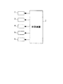
以下、図面を参照しながら、本発明の好ましい実施形態を詳細に説明する。図1は、本発明の一実施形態による飲料抽出装置をコーヒー抽出装置に適用し、これを備えたカップ式自動販売機の内部構造を模式的に示している。同図に示すように、このカップ式自動販売機1は、コーヒー抽出装置2により、コーヒー豆および湯を用いてコーヒーを抽出し、購入者にカップ入りのレギュラーコーヒーを提供するものである。なお、以下の説明ではまず、カップ式自動販売機1の内部構造について説明し、その後、コーヒー抽出装置2について詳述する。   Hereinafter, preferred embodiments of the present invention will be described in detail with reference to the drawings. FIG. 1 schematically shows the internal structure of a cup-type vending machine equipped with a beverage extraction device according to an embodiment of the present invention, applied to a coffee extraction device. As shown in the figure, this cup type vending machine 1 uses a coffee extraction device 2 to extract coffee using coffee beans and hot water, and provides regular coffee in a cup to the purchaser. In the following description, first, the internal structure of the cup-type vending machine 1 will be described, and then the coffee extraction device 2 will be described in detail.

図1に示すように、カップ式自動販売機1は、コーヒー抽出装置2と、このコーヒー抽出装置2に、所定量のコーヒー粉および湯をそれぞれ供給する原料供給装置3および給湯装置4と、コーヒー抽出装置2によって抽出されたコーヒーをクリームや砂糖とともに混合するミキシングボウル5と、このミキシングボウル5にクリームや砂糖を供給するクリーム・砂糖供給装置6とを備えている。また、これらは、図2に示すように、マイクロコンピュータを有する制御装置7によって制御される。   As shown in FIG. 1, a cup-type vending machine 1 includes a coffee extraction device 2, a raw material supply device 3 and a hot water supply device 4 for supplying a predetermined amount of coffee powder and hot water to the coffee extraction device 2, respectively, and coffee. A mixing bowl 5 for mixing the coffee extracted by the extraction device 2 together with cream and sugar, and a cream / sugar supply device 6 for supplying cream and sugar to the mixing bowl 5 are provided. Moreover, these are controlled by the control apparatus 7 which has a microcomputer, as shown in FIG.

原料供給装置3は、コーヒー豆を収納する複数(図1では2つのみ図示)のキャニスタ11と、コーヒー豆を挽くミル12とを備えている。販売時に、キャニスタ11からシュート11aを介してミル12に供給されたコーヒー豆は、ミル12によって粉末状に挽かれ、そのコーヒー粉(以下「原料」という)が、シュート12aを介してコーヒー抽出装置2に供給される。給湯装置4は、湯を貯留する温水タンク13を備えており、販売時に、温水タンク13から所定量の湯が給湯チューブ13aを介してコーヒー抽出装置2に供給される。ミキシングボウル5は、コーヒー抽出装置2によって抽出されたコーヒーを、クリーム・砂糖供給装置6からシュート6aを介して供給された所定量のクリームや砂糖とともに攪拌する。その後、ミキシングボウル5内のコーヒーは、ミキシングボウル5に接続された飲料チューブ5aを介してカップCに供給される。   The raw material supply device 3 includes a plurality of canisters 11 (only two are shown in FIG. 1) for storing coffee beans, and a mill 12 for grinding coffee beans. At the time of sale, the coffee beans supplied from the canister 11 to the mill 12 via the chute 11a are ground into a powder by the mill 12, and the coffee powder (hereinafter referred to as “raw material”) is extracted via the chute 12a to the coffee extraction device. 2 is supplied. The hot water supply device 4 includes a hot water tank 13 for storing hot water, and at the time of sale, a predetermined amount of hot water is supplied from the hot water tank 13 to the coffee extraction device 2 via the hot water supply tube 13a. The mixing bowl 5 stirs the coffee extracted by the coffee extraction device 2 together with a predetermined amount of cream and sugar supplied from the cream / sugar supply device 6 via the chute 6a. Thereafter, the coffee in the mixing bowl 5 is supplied to the cup C via the beverage tube 5 a connected to the mixing bowl 5.

次に、コーヒー抽出装置2について詳述する。図3および図4は、コーヒー抽出装置2を示している。両図に示すように、このコーヒー抽出装置2は、コーヒーを抽出するためのドリップユニット21(抽出ユニット)と、このドリップユニット21を駆動する駆動ユニット22で構成されている。駆動ユニット22は、自動販売機1内にねじ止めなどで固定されており、この駆動ユニット22に、ドリップユニット21が着脱自在に取り付けられている。   Next, the coffee extraction device 2 will be described in detail. 3 and 4 show the coffee brewing device 2. As shown in both the drawings, the coffee extraction device 2 includes a drip unit 21 (extraction unit) for extracting coffee and a drive unit 22 that drives the drip unit 21. The drive unit 22 is fixed in the vending machine 1 by screwing or the like, and the drip unit 21 is detachably attached to the drive unit 22.

ドリップユニット21は、原料および湯が供給され、内部においてコーヒーの抽出を行うためのシリンダ23と、このシリンダ23を着脱自在に収容するシリンダホルダ24とで構成されている。図5は、シリンダ23がシリンダホルダ24から取り外された状態を示している。このシリンダ23は、プラスチックから成り、同図および図6に示すように、上下方向に延びるとともに、上面および下面が開放した円筒状に形成されている。また、シリンダ23の外周面には、シリンダ23をシリンダホルダ24に着脱する際に利用される取っ手25およびガイド部26が設けられている。ガイド部26は、互いに上下方向に所定間隔を隔てて設けられ、上下対称に形成された上下2つのガイド部26、26で構成されている。   The drip unit 21 is composed of a cylinder 23 that is supplied with raw materials and hot water and extracts coffee therein, and a cylinder holder 24 that detachably accommodates the cylinder 23. FIG. 5 shows a state where the cylinder 23 is removed from the cylinder holder 24. The cylinder 23 is made of plastic and is formed in a cylindrical shape extending in the vertical direction and having an upper surface and a lower surface opened as shown in FIG. In addition, a handle 25 and a guide portion 26 that are used when the cylinder 23 is attached to and detached from the cylinder holder 24 are provided on the outer peripheral surface of the cylinder 23. The guide part 26 is provided with two upper and lower guide parts 26, 26 that are provided vertically apart from each other at a predetermined interval and are formed vertically symmetrical.

各ガイド部26は、シリンダ23の中央寄りの内側ガイド部27と、シリンダ23の開放端寄りの外側ガイド部28とで、上下2段に構成されている。内側ガイド部27は、シリンダ23の中心よりも若干、取っ手25寄りの位置から、シリンダ23の取っ手25と反対側の外周面付近まで水平に延びるとともに、平面形状が凹字状に形成されている。一方、外側ガイド部28は、内側ガイド部27よりも一回り小さく形成されている。また、内側ガイド部27の基端部(取っ手25側の端部)27aは、外側ガイド部28を越えて、シリンダ23の開放端側に延びるように形成されている。以上のように、シリンダ23は、上下対称に形成されているので、その上下の向きに関わらず、シリンダホルダ24に取り付け可能である。   Each guide portion 26 is configured in two upper and lower stages by an inner guide portion 27 near the center of the cylinder 23 and an outer guide portion 28 near the open end of the cylinder 23. The inner guide portion 27 extends horizontally from a position slightly closer to the handle 25 than the center of the cylinder 23 to the vicinity of the outer peripheral surface on the opposite side of the handle 25 of the cylinder 23, and the planar shape is formed in a concave shape. . On the other hand, the outer guide portion 28 is formed slightly smaller than the inner guide portion 27. Further, a base end portion (end portion on the handle 25 side) 27 a of the inner guide portion 27 is formed so as to extend beyond the outer guide portion 28 to the open end side of the cylinder 23. As described above, since the cylinder 23 is formed symmetrically in the vertical direction, it can be attached to the cylinder holder 24 regardless of the vertical direction.

図7に示すように、シリンダホルダ24は、内側にシリンダ収容部24aを有するボックス状のフレーム31と、このフレーム31内の下部に昇降自在に設けられ、シリンダ23内のコーヒーをろ過しながら外部に搬送するためのフィルタブロック32と、フレーム31内の下部に前後方向にスライド自在に設けられ、フィルタブロック32上に残留した抽出滓を除去するためのスクレーパ33と、フレーム31内に設けられ、シリンダ収容部24aに収容されたシリンダ23を左右から挟んだ状態で保持するシリンダキャッチャ34と、フレーム31の前面を開閉する前面カバー35(カバー)などを備えている。   As shown in FIG. 7, the cylinder holder 24 is provided in a box-like frame 31 having a cylinder accommodating portion 24 a on the inner side and a lower portion in the frame 31 so as to be movable up and down. A filter block 32 for transporting to the bottom of the frame 31 slidably provided in the lower part of the frame 31, and provided in the frame 31, a scraper 33 for removing the extraction residue remaining on the filter block 32, A cylinder catcher 34 that holds the cylinder 23 accommodated in the cylinder accommodating portion 24a from the left and right sides, a front cover 35 (cover) that opens and closes the front surface of the frame 31, and the like are provided.

フレーム31は、互いに所定間隔を隔てて対向する左右の側壁41、41と、両側壁41、41の後端部間および下端部間にわたるようにそれぞれ設けられた背壁42および底壁43とを有し、前面および上面が開放したボックス状に形成されている。また、左右の側壁41、41の前側の上端部には、両側壁41、41間を連結する前上カバー36が設けられている。なお、図示しないが、底壁43は、棒状の複数の支持部材によって格子状に形成されている。   The frame 31 includes left and right side walls 41, 41 facing each other at a predetermined interval, and a back wall 42 and a bottom wall 43 provided so as to extend between the rear end portions and the lower end portions of the side walls 41, 41, respectively. It has a box shape with the front and top surfaces open. Further, a front upper cover 36 that connects the side walls 41 and 41 is provided at the upper end of the front side of the left and right side walls 41 and 41. Although not shown, the bottom wall 43 is formed in a lattice shape by a plurality of rod-shaped support members.

各側壁41は、側面形状がほぼ矩形状に形成されるとともに、外側の側面が開放したケース状の側壁本体44と、その開放した側面を覆うように、側壁本体44にねじ止めされた外カバー45とを備えている。そして、図8に示すように、各側壁41内には、フィルタブロック32および後述するシリンダヘッド111を駆動することによって、シリンダ23の下面および上面をそれぞれ開閉するシリンダ開閉機構51(抽出機構)が設けられている。なお、左右のシリンダ開閉機構51、51は、左右の側壁41、41内に、ほぼ左右対称に構成されているので、以下の説明では、右側壁41に内蔵されたものを中心に説明する。   Each side wall 41 is formed in a substantially rectangular shape on the side surface, a case-shaped side wall main body 44 whose outer side surface is open, and an outer cover screwed to the side wall main body 44 so as to cover the open side surface. 45. As shown in FIG. 8, in each side wall 41, a cylinder opening / closing mechanism 51 (extraction mechanism) that opens and closes the lower surface and the upper surface of the cylinder 23 by driving the filter block 32 and a cylinder head 111 described later. Is provided. Since the left and right cylinder opening / closing mechanisms 51 and 51 are substantially symmetrical in the left and right side walls 41 and 41, the following description will focus on what is built in the right side wall 41.

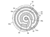
図8および図9に示すように、シリンダ開閉機構51は、側壁本体44内の中央付近の所定位置に突設された支軸44aに回転自在に支持され、所定形状の第1および第2カム溝53、54を有するカム円板55と、側壁本体44内の下部に上下方向にスライド自在に設けられ、カム円板55の第1カム溝53に係合するとともにシリンダブロック32に連結されたスライダ56と、側壁本体44内の上部の所定位置に突設された支軸44bに回動自在に支持され、カム円板55の第2カム溝54に係合するとともに後述するシリンダヘッド111をシリンダ23の上面に押圧した状態でロックするためのシリンダヘッドロック部材57とを備えている。   As shown in FIGS. 8 and 9, the cylinder opening / closing mechanism 51 is rotatably supported by a support shaft 44 a protruding at a predetermined position near the center in the side wall main body 44, and has first and second cams having a predetermined shape. A cam disk 55 having grooves 53, 54 and a lower part in the side wall body 44 are slidable in the vertical direction, engage with the first cam groove 53 of the cam disk 55 and are connected to the cylinder block 32. A slider 56 and a support shaft 44b protruding at a predetermined position in the upper portion of the side wall main body 44 are rotatably supported, engage with a second cam groove 54 of the cam disc 55, and a cylinder head 111 described later. A cylinder head lock member 57 for locking the cylinder 23 in a pressed state is provided.

カム円板55は、所定の直径および厚さを有する円板状に形成されており、周面全体にギヤ部55aが形成されている。また、カム円板55の外カバー45側の周縁部には、ほぼ1/2円弧分、径方向に若干突出した凸部55bが設けられている。さらに、カム円板55の側壁本体44側の側面に、前記第1および第2カム溝53、54が設けられている。   The cam disc 55 is formed in a disc shape having a predetermined diameter and thickness, and a gear portion 55a is formed on the entire peripheral surface. Further, a convex portion 55b that protrudes slightly in the radial direction by approximately 1/2 arc is provided at the peripheral portion of the cam disk 55 on the outer cover 45 side. Further, the first and second cam grooves 53 and 54 are provided on the side surface of the cam disk 55 on the side wall main body 44 side.

図10に示すように、第1カム溝53は、カム円板55の側面の周縁部に設けられ、カム円板55の支軸44aを中心とする円弧状にかつ反時計方向にほぼ一周するように延びる外側カム部61と、この外側カム部61に連なり、支軸44aに向かって円弧状に延びる駆動カム部62と、この駆動カム部62に連なり、支軸44aを中心とする円弧状にかつ支軸44aの付近でほぼ一周するように延びる内側カム部63とで構成されている。なお、この第1カム溝53の外側カム部61の先端部には、支軸44a側に凹むように形成された凹部61aが設けられている。一方、第2カム溝54は、第1カム溝53の外側カム部61よりも内側に設けられ、支軸44aを中心とする円弧状にかつ外側カム部61の先端部付近から反時計方向にほぼ3/4円弧状に延びる外側カム部64と、この外側カム部64に連なり、支軸44aに向かって延びる駆動カム部65と、この駆動カム部65に連なり、支軸44aを中心とする円弧状に延びる内側カム部66とで構成されている。   As shown in FIG. 10, the first cam groove 53 is provided at the peripheral edge portion of the side surface of the cam disk 55, and is substantially circular in the arc shape centering on the support shaft 44 a of the cam disk 55 and counterclockwise. The outer cam portion 61 extending in this manner, the driving cam portion 62 connected to the outer cam portion 61 and extending in an arc shape toward the support shaft 44a, and the arc shape centering on the support shaft 44a connected to the drive cam portion 62 And an inner cam portion 63 extending so as to make one round in the vicinity of the support shaft 44a. A recess 61a is formed at the tip of the outer cam portion 61 of the first cam groove 53 so as to be recessed toward the support shaft 44a. On the other hand, the second cam groove 54 is provided on the inner side of the outer cam portion 61 of the first cam groove 53, has an arc shape centering on the support shaft 44a, and counterclockwise from the vicinity of the distal end portion of the outer cam portion 61. An outer cam portion 64 that extends in a substantially ¾ arc shape, a drive cam portion 65 that extends to the outer cam portion 64 and extends toward the support shaft 44a, and that continues to the drive cam portion 65, with the support shaft 44a as the center. It is comprised with the inner side cam part 66 extended in circular arc shape.

スライダ56は、図9(b)に示すように、上下方向に延びるとともに下部が下方に向かって拡幅していて、ほぼ凸字状に形成されている。このスライダ56の上端部には、カム円板55側に突出する係合凸部56aが設けられており、この係合凸部56aが、カム円板55の第1カム溝53に摺動自在に係合している。また、スライダ56の下端部には、スライダ56と前記フィルタブロック32とを連結する2本の連結シャフト71、71が固定されている。両連結シャフト71、71は、互いに前後方向(図9では左右方向)に間隔を隔てかつ左右方向(図9では図の表裏方向)に平行に延びている。各連結シャフト71は、側壁本体44の上下方向に延びる長孔44cを貫通し、一端部が上記スライダ56に固定される一方、他端部が左側のシリンダ開閉機構51のスライダ56に固定されている。したがって、フィルタブロック32は、両連結シャフト71、71を介して、左右のスライダ56、56に支持されている。また、スライダ56の中央部には、上下方向に延びる長孔56bが形成されており、この長孔56bに、側壁本体44内の下部の所定位置に突設された支軸44dが摺動自在に貫通している。   As shown in FIG. 9B, the slider 56 extends in the vertical direction and has a lower portion that widens downward, and has a substantially convex shape. An engagement convex portion 56 a that protrudes toward the cam disk 55 is provided at the upper end portion of the slider 56, and the engagement convex portion 56 a is slidable in the first cam groove 53 of the cam disk 55. Is engaged. Two connecting shafts 71, 71 that connect the slider 56 and the filter block 32 are fixed to the lower end of the slider 56. Both the connecting shafts 71, 71 extend in parallel to each other in the left-right direction (the front-back direction in the drawing in FIG. 9) with a space in the front-rear direction (the left-right direction in FIG. 9). Each connecting shaft 71 passes through a long hole 44 c extending in the vertical direction of the side wall main body 44, and one end is fixed to the slider 56, while the other end is fixed to the slider 56 of the left cylinder opening / closing mechanism 51. Yes. Therefore, the filter block 32 is supported by the left and right sliders 56 and 56 via both connecting shafts 71 and 71. In addition, a long hole 56b extending in the vertical direction is formed in the center of the slider 56, and a support shaft 44d protruding at a predetermined position in the lower portion of the side wall body 44 is slidable in the long hole 56b. Has penetrated.

以上のように構成されたスライダ56は、カム円板55の回転に伴い、側壁本体44内の上下方向に延びる一対のガイドレール44e、44e間に案内されながら、上下方向にスライドする。これに伴い、フィルタブロック32が昇降し、シリンダ23の下面を開閉する。具体的には、図8(a)および図9に示すカム円板55が、両図の時計方向に回転し、スライダ56の係合凸部56aが、第1カム溝53の外側カム部61から内側カム部63に向かって、駆動カム部62を摺動することにより、スライダ56が上昇する。そして、スライダ56の係合凸部56aが、内側カム部63に到達することにより、フィルタブロック32がシリンダ23の下面に密着した状態で、これを閉鎖する(図26(b)参照)。一方、その状態から、カム円板55が、反時計方向に回転し、スライダ56が下降することにより、フィルタブロック32も下降し、それにより、シリンダ23の下面が開放される(図28(a)参照)。   The slider 56 configured as described above slides in the vertical direction while being guided between the pair of guide rails 44e and 44e extending in the vertical direction in the side wall main body 44 as the cam disk 55 rotates. Along with this, the filter block 32 moves up and down to open and close the lower surface of the cylinder 23. Specifically, the cam disk 55 shown in FIG. 8A and FIG. 9 rotates in the clockwise direction in both drawings, and the engaging convex portion 56 a of the slider 56 becomes the outer cam portion 61 of the first cam groove 53. When the drive cam 62 is slid from the inner cam 63 toward the inner cam 63, the slider 56 is raised. Then, when the engaging projection 56a of the slider 56 reaches the inner cam portion 63, the filter block 32 is closed in close contact with the lower surface of the cylinder 23 (see FIG. 26B). On the other hand, from this state, the cam disk 55 rotates counterclockwise and the slider 56 descends, so that the filter block 32 also descends, thereby opening the lower surface of the cylinder 23 (FIG. 28 (a)). )reference).

図7、8および11に示すように、フィルタブロック32は、コーヒーをろ過するための多数の細孔72aを有するとともにシリンダ23の内径よりも一回り小さく形成された円形のフィルタ72と、このフィルタ72の周囲を囲むように設けられ、上面が平らに形成されるとともに、シリンダ23の下面よりも大きな外径を有する幅広リング状のパッキン73と、これらを上面において支持するとともに、上下に連通した通路を有するブロック状の支持部材74などで構成されている。このフィルタブロック32は、前述したように、スライダ56の上下方向のスライドに伴って昇降し、シリンダ23の下面の閉鎖時には、パッキン73の上面がシリンダ23の下面周縁部に当接した状態で、これをシールする。また、フィルタブロック32の支持部材74と、右側壁41の背面下端部に設けられたジョイントホース40(図8参照)との間には、フィルタブロックチューブ32aが接続されている。なお、ジョイントホース40は、ドリップユニット21が駆動ユニット22に取り付けられた状態において、駆動ユニット22側の後述するジョイントホース120に接続される。   As shown in FIGS. 7, 8 and 11, the filter block 32 includes a circular filter 72 having a large number of pores 72 a for filtering coffee and formed slightly smaller than the inner diameter of the cylinder 23, and the filter block 32. 72, and a wide ring-shaped packing 73 having a larger outer diameter than the lower surface of the cylinder 23, and supporting these on the upper surface, and communicating with the upper and lower sides. A block-like support member 74 having a passage is used. As described above, the filter block 32 moves up and down as the slider 56 slides in the vertical direction, and when the lower surface of the cylinder 23 is closed, the upper surface of the packing 73 is in contact with the peripheral surface of the lower surface of the cylinder 23. Seal this. Further, a filter block tube 32 a is connected between the support member 74 of the filter block 32 and the joint hose 40 (see FIG. 8) provided at the lower rear end portion of the right side wall 41. The joint hose 40 is connected to a joint hose 120 described later on the drive unit 22 side in a state where the drip unit 21 is attached to the drive unit 22.

また、図8(a)および図9に示すように、右側の側壁41の下端部には、上記ジョイントホース40に接続された廃液チューブ50が設けられるとともに、この廃液チューブ50を開閉する廃液チューブピンチ部材58が設けられている。廃液チューブ50は、ゴムなどの弾性材で構成されており、ジョイントホース40から前方に水平に延びる水平部50aを有し、この水平部50aから下方に延びている。また、廃液チューブピンチ部材58は、上下方向に延びる板状に形成されており、上端部には、スライダ56の長孔56bに摺動自在に係合する係合凸部58aが設けられる一方、下端部には、廃液チューブ50の水平部50aの下側に、これを横切るように突出しかつ台形状の断面を有する押圧部58bが設けられている。さらに、廃液チューブ50の水平部50aの上側には、廃液チューブピンチ部材58と協働して廃液チューブ50をピンチし、これを閉鎖するための押さえばね59が設けられている。この押さえばね59は、細長い板ばねで構成されており、廃液チューブ50の水平部50aに沿って延び、これに接するように配置されている。また、押さえばね59の両端部は、上方に折り曲げられ、側壁本体44内の廃液チューブピンチ部材58の前後(図9では左右)に設けられた2つの支持部44f、44fに支持されている。   As shown in FIGS. 8A and 9, a waste liquid tube 50 connected to the joint hose 40 is provided at the lower end portion of the right side wall 41, and a waste liquid tube that opens and closes the waste liquid tube 50. A pinch member 58 is provided. The waste liquid tube 50 is made of an elastic material such as rubber, and has a horizontal portion 50a that extends horizontally forward from the joint hose 40, and extends downward from the horizontal portion 50a. In addition, the waste tube pinch member 58 is formed in a plate shape extending in the vertical direction, and an engaging convex portion 58a that is slidably engaged with the long hole 56b of the slider 56 is provided on the upper end portion, At the lower end portion, a pressing portion 58b is provided below the horizontal portion 50a of the waste liquid tube 50 so as to protrude across the lower portion and have a trapezoidal cross section. Further, on the upper side of the horizontal portion 50a of the waste liquid tube 50, a pressing spring 59 is provided for pinching the waste liquid tube 50 in cooperation with the waste liquid tube pinch member 58 and closing it. The presser spring 59 is constituted by an elongated leaf spring, and is disposed so as to extend along the horizontal portion 50a of the waste liquid tube 50 and to be in contact therewith. Further, both end portions of the holding spring 59 are bent upward and are supported by two support portions 44f and 44f provided on the front and rear (left and right in FIG. 9) of the waste liquid tube pinch member 58 in the side wall main body 44.

上記のように構成された廃液チューブピンチ部材58は、カム円板55の回転に伴うスライダ55の昇降に連動して、昇降する。具体的には、図9に示す状態から、スライダ56が上昇すると、その長孔56bの下端部が廃液チューブピンチ部材58の係合凸部58aに当接する。そして、スライダ56がさらに上昇すると、廃液チューブピンチ部材58が、係合凸部58aを介して持ち上げられることにより、上昇する。それにより、廃液チューブピンチ部材58の押圧部58bが、廃液チューブ50の水平部50aを下方から押し潰し、それにより、廃液チューブ50が閉鎖される(図26(b)参照)。なお、この状態から、スライダ56が下降することにより、廃液チューブピンチ部材58も下降し、元の位置に戻る。   The waste liquid tube pinch member 58 configured as described above moves up and down in conjunction with the up and down movement of the slider 55 accompanying the rotation of the cam disk 55. Specifically, when the slider 56 is lifted from the state shown in FIG. 9, the lower end portion of the long hole 56 b comes into contact with the engaging convex portion 58 a of the waste liquid tube pinch member 58. When the slider 56 is further raised, the waste liquid tube pinch member 58 is raised by being lifted through the engaging convex portion 58a. Thereby, the pressing part 58b of the waste liquid tube pinch member 58 crushes the horizontal part 50a of the waste liquid tube 50 from below, and thereby the waste liquid tube 50 is closed (see FIG. 26B). From this state, when the slider 56 descends, the waste tube pinch member 58 also descends and returns to its original position.

また、図9(b)に示すように、シリンダヘッドロック部材57は、上下方向に延びる所定形状に形成され、その中心部が、側壁本体44内の支軸44bに回動自在に支持されている。シリンダヘッドロック部材57の下端部には、カム円板55側に突出した係合凸部57aが設けられており、この係合凸部57aが、カム円板55の前記第2カム溝54に摺動自在に係合している。また、シリンダヘッドロック部材57の上端部には、後方に突出するように延びる鉤状のロック部57bが設けられている。   Further, as shown in FIG. 9B, the cylinder head lock member 57 is formed in a predetermined shape extending in the vertical direction, and its central portion is rotatably supported by the support shaft 44b in the side wall body 44. Yes. At the lower end portion of the cylinder head lock member 57, an engaging convex portion 57a protruding toward the cam disc 55 is provided, and this engaging convex portion 57a is formed in the second cam groove 54 of the cam disc 55. It is slidably engaged. In addition, a hook-shaped lock portion 57 b extending so as to protrude rearward is provided at the upper end portion of the cylinder head lock member 57.

このように構成されたシリンダヘッドロック部材57は、カム円板55の回転に伴って回動し、上端部のロック部57bによって、後述するシリンダヘッド111をシリンダ23の上面に押圧しかつロックすることにより、シリンダ23の上面を閉鎖する。具体的には、図9(b)および図10に示すカム円板55が、両図の時計方向に回転し、シリンダヘッドロック部材57の係合凸部57aが、第2カム溝54の外側カム部64から内側カム部66に向かって、駆動カム部65を摺動することにより、シリンダヘッドロック部材57が、支軸44bを中心として、図9(b)の時計方向に回動する。そして、シリンダヘッドロック部材57のロック部57bが、シリンダヘッド111の上部のヘッドガイドシャフト114に係合するとともに、これを下方に押し下げるようにロックする。それにより、シリンダヘッド111がシリンダ23の上面に密着した状態で、これを閉鎖する(図27(b)参照)。   The cylinder head locking member 57 configured in this manner rotates with the rotation of the cam disk 55, and presses and locks a cylinder head 111 (to be described later) against the upper surface of the cylinder 23 by the lock portion 57b at the upper end. As a result, the upper surface of the cylinder 23 is closed. Specifically, the cam disk 55 shown in FIG. 9B and FIG. 10 rotates in the clockwise direction in both figures, and the engagement convex portion 57a of the cylinder head lock member 57 is located outside the second cam groove 54. By sliding the drive cam portion 65 from the cam portion 64 toward the inner cam portion 66, the cylinder head lock member 57 rotates about the support shaft 44b in the clockwise direction in FIG. 9B. Then, the lock portion 57b of the cylinder head lock member 57 engages with the head guide shaft 114 at the top of the cylinder head 111 and locks it so as to push it down. Thereby, the cylinder head 111 is closed in a state of being in close contact with the upper surface of the cylinder 23 (see FIG. 27B).

以上のように構成されたシリンダ開閉機構51は、前述したように、左右の側壁41、41にそれぞれ内蔵されており、両シリンダ開閉機構51、51のカム円板55のギヤ部55a、55aが、対応する側壁本体44内の所定位置に回転自在に設けられたギヤ76、76に噛み合っている。図8に示すように、両ギヤ76、76は、左右方向に水平に延びる動力伝達シャフト75の両端部に固定されており、各ギヤ76が対応する側壁本体44内の後端部の上下方向の中央部に配置されている。左側の側壁本体44に設けられたギヤ76(以下「従動ジョイントギヤ76A」という)は、後方に若干露出しており、ドリップユニット21が駆動ユニット22に取り付けられた状態において、駆動ユニット22側の後述する駆動ジョイントギヤ134に噛み合う。したがって、従動ジョイントギヤ76aが回転すると、これに噛み合う左側のカム円板55が回転し、動力伝達シャフト75および右側のギヤ76を介して、右側のカム円板55が左側のそれに同期して回転する。   The cylinder opening / closing mechanism 51 configured as described above is built in the left and right side walls 41, 41 as described above, and the gear portions 55a, 55a of the cam disks 55 of both the cylinder opening / closing mechanisms 51, 51 are provided. , Meshed with gears 76, 76 that are rotatably provided at predetermined positions in the corresponding side wall main body 44. As shown in FIG. 8, both gears 76 are fixed to both ends of a power transmission shaft 75 extending horizontally in the left-right direction, and the vertical direction of the rear end in the side wall body 44 to which each gear 76 corresponds. It is arranged at the center of the. A gear 76 (hereinafter referred to as “driven joint gear 76 </ b> A”) provided on the left side wall main body 44 is slightly exposed to the rear, and in a state where the drip unit 21 is attached to the drive unit 22, It meshes with a drive joint gear 134 described later. Therefore, when the driven joint gear 76a rotates, the left cam disk 55 meshing with it rotates, and the right cam disk 55 rotates in synchronization with the left side via the power transmission shaft 75 and the right gear 76. To do.

次に、スクレーパ33について説明する。図7および図11に示すように、スクレーパ33は、平面形状がフィルタブロック32のそれよりも大きい矩形枠状に形成されたサポート77と、ゴムなどから成り、サポート77の底面前端部に、これに沿って左右方向に延びるとともに垂下するように取り付けられたスクレーパ本体78とで構成されている。図11に示すように、サポート77の後端部(同図では上端部)には、左右方向に延びるとともに上方に開放した溝部77aが設けられている。また、この溝部77aの左右方向のほぼ中央部には、後方に開放した開放部77bが設けられている。   Next, the scraper 33 will be described. As shown in FIGS. 7 and 11, the scraper 33 is composed of a support 77 formed in a rectangular frame shape whose planar shape is larger than that of the filter block 32, rubber, and the like. And a scraper main body 78 attached so as to hang down and extend in the left-right direction. As shown in FIG. 11, a groove 77 a that extends in the left-right direction and opens upward is provided at the rear end portion (upper end portion in the figure) of the support 77. In addition, an open portion 77b opened rearward is provided at a substantially central portion in the left-right direction of the groove portion 77a.

このように構成されたスクレーパ33は、左右の側壁41、41間にガイドされながら、前後方向にスライド可能になっている。そして、このスクレーパ33が、後述するスクレーパ・シリンダヘッド駆動機構123によって後方へ駆動されることにより、前端部のスクレーパ本体78がフィルタブロック32上を後方に向かって摺動する。それにより、コーヒー抽出後にフィルタブロック32上に残留した抽出滓は、スクレーパ本体78で掻き取られ、駆動ユニット22の後述する滓シュート161を介して外部に排出される。   The scraper 33 configured in this manner is slidable in the front-rear direction while being guided between the left and right side walls 41. The scraper 33 is driven rearward by a scraper / cylinder head driving mechanism 123 described later, so that the scraper body 78 at the front end slides rearward on the filter block 32. Thereby, the extracted soot remaining on the filter block 32 after the coffee extraction is scraped off by the scraper body 78 and discharged to the outside via the soot chute 161 described later of the drive unit 22.

また、左右の側壁41、41には、ドリップユニット21を駆動ユニット22に着脱するためのドリップユニット着脱機構81、81が設けられている。これらのドリップユニット着脱機構81、81も、上述したシリンダ開閉機構51と同様、左右対称に設けられているので、以下の説明では、右側壁41に内蔵されたものを中心に説明する。   The left and right side walls 41, 41 are provided with drip unit attaching / detaching mechanisms 81, 81 for attaching / detaching the drip unit 21 to / from the drive unit 22. Since these drip unit attaching / detaching mechanisms 81 and 81 are also provided symmetrically in the same manner as the cylinder opening / closing mechanism 51 described above, the following description will focus on what is built in the right side wall 41.

図8および図9に示すように、ドリップユニット着脱機構81は、側壁本体44内の後端部に上下方向にスライド自在に設けられたユニットロック部材82(取付け部材)と、このユニットロック部材82を下方に付勢するばね83と、ドリップユニット21を駆動ユニット22から取り外す際に操作される取外しレバー84(操作部材)とを備えている。   As shown in FIGS. 8 and 9, the drip unit attaching / detaching mechanism 81 includes a unit lock member 82 (attachment member) that is slidable in the vertical direction at the rear end portion in the side wall body 44, and the unit lock member 82. And a removal lever 84 (operation member) that is operated when the drip unit 21 is removed from the drive unit 22.

ユニットロック部材82は、上下方向に延びており、上下端部にそれぞれ、後方(図9では右方)に突出する鉤状のロック部82a、82aが設けられている。また、ユニットロック部材82の上下端部にはそれぞれ、上下方向に延びるガイド孔82b、82bが設けられており、各ガイド孔82bに、側壁本体44内の所定位置に突設されたガイド凸部44gが摺動自在に係合している。さらに、ユニットロック部材82の上下方向のほぼ中央部には、カム円板55側に突出する係合凸部82cが設けられており、この係合凸部82cが、カム円板55の第1カム溝53に摺動自在に係合している。また、ユニットロック部材82の下部には、取外しレバー84の後端部84bの直ぐ上、およびその後端部84bよりも若干下方にそれぞれ、外カバー45側に突出する上凸部82dおよび下凸部82eが設けられている。   The unit lock member 82 extends in the vertical direction, and is provided with hook-shaped lock portions 82a and 82a that protrude rearward (rightward in FIG. 9) at the upper and lower ends, respectively. Further, upper and lower end portions of the unit lock member 82 are provided with guide holes 82b and 82b extending in the vertical direction, respectively, and guide convex portions projecting at predetermined positions in the side wall body 44 in the respective guide holes 82b. 44g is slidably engaged. Further, an engagement convex portion 82 c that protrudes toward the cam disk 55 is provided at a substantially central portion in the vertical direction of the unit lock member 82, and this engagement convex portion 82 c is a first portion of the cam disk 55. The cam groove 53 is slidably engaged. Further, at the lower part of the unit lock member 82, there are an upper convex portion 82d and a lower convex portion that protrude to the outer cover 45 side, just above the rear end portion 84b of the removal lever 84 and slightly below the rear end portion 84b, respectively. 82e is provided.

取外しレバー84は、前後方向に延び、その中央部において、前記支軸44dに回動自在に支持されている。取外しレバー84の前端部84aは、側壁41の外部に臨むとともに、側壁41の前部に設けられかつ前方に開放した凹部41aの内側に位置している。また、取外しレバー84の後端部84bは、側面形状がL字状に形成され、ユニットロック部材82の前記上凸部82dに下方から当接している。   The detaching lever 84 extends in the front-rear direction, and is supported at the central portion thereof so as to be rotatable on the support shaft 44d. The front end portion 84a of the removal lever 84 faces the outside of the side wall 41, and is located inside a recess 41a provided at the front portion of the side wall 41 and opened forward. Further, the rear end portion 84b of the removal lever 84 is formed in an L shape on the side surface, and is in contact with the upper convex portion 82d of the unit lock member 82 from below.

以上のように構成されたドリップユニット着脱機構81により、ドリップユニット21が駆動ユニット22に取り付けられた状態では、ユニットロック部材82の上下のロック部82a、82aが、それらにそれぞれ対応する駆動ユニット22側の後述する係合孔108d(図4および図16(a)参照)に係止される。それにより、ドリップユニット21は、駆動ユニット22にロックされた状態で、しっかりと取り付けられる。また、ドリップユニット21を駆動ユニット22から取り外す場合には、図12(a)に示す状態(待機位置)から、左右の取外しレバー84、84の前端部84a、84aを同時に押し下げる。それにより、同図(b)に示すように、ユニットロック部材82は、上凸部82dを介して、取外しレバー84によりばね83の付勢力に抗して押し上げられ、それにより、駆動ユニット22側の係合孔108dに対するロック部82aの係止が解除される。そして、その状態のまま、ドリップユニット21を前方に引き出すことにより、ドリップユニット21が駆動ユニット22から取り外される。   When the drip unit 21 is attached to the drive unit 22 by the drip unit attaching / detaching mechanism 81 configured as described above, the upper and lower lock portions 82a and 82a of the unit lock member 82 correspond to the drive units 22 respectively corresponding thereto. It is locked in an engagement hole 108d (see FIGS. 4 and 16A), which will be described later. Thereby, the drip unit 21 is securely attached in a state where it is locked to the drive unit 22. When removing the drip unit 21 from the drive unit 22, the front end portions 84a and 84a of the left and right release levers 84 and 84 are simultaneously pushed down from the state (standby position) shown in FIG. As a result, as shown in FIG. 5B, the unit lock member 82 is pushed up against the urging force of the spring 83 by the removal lever 84 via the upper convex portion 82d. The locking portion 82a is released from the engagement hole 108d. In this state, the drip unit 21 is removed from the drive unit 22 by pulling the drip unit 21 forward.

また、図9(b)に示すように、カム円板55が待機位置に位置する場合、ユニットロック部材82の係合凸部82cは、第1カム溝53の外側カム部61の先端部に位置している。そのため、上記のように、取外しレバー84が操作された際には、係合凸部82cが外側カム部61の先端部の凹部61aにより、上方への移動が許容され、それにより、取外しレバー84の操作が可能となる。これに対し、カム円板55が待機位置に位置していない場合、例えばカム円板55が回転中である場合などには、ユニットロック部材82の係合凸部82cは、第1カム溝53によって、上方への移動が規制される(例えば図26(b)参照)。それにより、ユニットロック部材82の上方への移動が不能になるとともに、取外しレバー84の操作も不能となる。したがって、駆動ユニット22からのドリップユニット21の取り外しは、カム円板55が待機位置に位置する場合にのみ可能であり、カム円板55が回転中である場合などに、ドリップユニット21が誤って取り外されるのを防止することができる。   9B, when the cam disk 55 is positioned at the standby position, the engagement convex portion 82c of the unit lock member 82 is located at the distal end portion of the outer cam portion 61 of the first cam groove 53. positioned. Therefore, as described above, when the removal lever 84 is operated, the engagement convex portion 82c is allowed to move upward by the concave portion 61a at the distal end portion of the outer cam portion 61, thereby the removal lever 84. Can be operated. On the other hand, when the cam disk 55 is not positioned at the standby position, for example, when the cam disk 55 is rotating, the engaging convex portion 82c of the unit lock member 82 has the first cam groove 53. Therefore, the upward movement is restricted (see, for example, FIG. 26B). As a result, the unit lock member 82 cannot be moved upward, and the removal lever 84 cannot be operated. Accordingly, the drip unit 21 can be detached from the drive unit 22 only when the cam disk 55 is located at the standby position. When the cam disk 55 is rotating, the drip unit 21 is erroneously removed. It can be prevented from being removed.

また、図示は省略するが、ドリップユニット21の背面側には、ドリップユニット21を駆動ユニット22から取り外したときに、カム円板55を回転不能にするためのカムロック機構が設けられている。具体的には、左側のカム円板55に噛み合う従動ジョイントギヤ76Aに対して進退自在のロック部材と、このロック部材を従動ジョイントギヤ76A側に付勢するばねなどで構成されている。ドリップユニット21が駆動ユニット22から取り外されたときには、ロック部材が従動ジョイントギヤ76A側に移動し、これに係合することで、そのギヤ76Aを回転不能にする。これにより、従動ジョイントギヤ76Aに噛み合うカム円板55も回転不能となる。一方、ドリップユニット21が駆動ユニット22に取り付けられたときには、駆動ユニット22側に設けられたロック解除部材が、ドリップユニット21側のロック部材に係合し、これを従動ジョイントギヤ76Aと反対方向に移動させることで、ロック部材による従動ジョイントギヤ76Aのロックを解除する。これにより、従動ジョイントギヤ76Aが回転可能となり、それにより、カム円板55も回転可能となる。   Although not shown, a cam lock mechanism is provided on the back side of the drip unit 21 so that the cam disk 55 cannot rotate when the drip unit 21 is removed from the drive unit 22. Specifically, it is configured by a lock member that can freely advance and retreat with respect to the driven joint gear 76A meshing with the left cam disk 55, and a spring that urges the lock member toward the driven joint gear 76A. When the drip unit 21 is removed from the drive unit 22, the lock member moves to the driven joint gear 76A side and engages with this to make the gear 76A non-rotatable. As a result, the cam disk 55 meshing with the driven joint gear 76A also cannot be rotated. On the other hand, when the drip unit 21 is attached to the drive unit 22, the unlocking member provided on the drive unit 22 side engages with the lock member on the drip unit 21 side, and this is opposite to the driven joint gear 76A. By moving, the lock of the driven joint gear 76A by the lock member is released. As a result, the driven joint gear 76A can rotate, and the cam disk 55 can also rotate.

上記のように、ドリップユニット21が駆動ユニット22から取り外された状態において、カム円板55を回転不能にロックするのは、次の理由による。すなわち、カム円板55の回転角度の制御は、後述するように、駆動ユニット22側に設けられ、カム円板55と同期して回転するスイッチギヤ136aを有するモードスイッチ136を利用して行われる。そのため、スイッチギヤ136aとカム円板55の回転角度の整合性を保つ必要があるからである。   As described above, in the state where the drip unit 21 is detached from the drive unit 22, the cam disk 55 is locked so as not to rotate for the following reason. That is, the control of the rotation angle of the cam disk 55 is performed using a mode switch 136 provided on the drive unit 22 side and having a switch gear 136a that rotates in synchronization with the cam disk 55, as will be described later. . Therefore, it is necessary to maintain the consistency of the rotation angle between the switch gear 136a and the cam disk 55.

なお、左右の側壁本体44、44の背面にはそれぞれ、後方に突出する上下2つのガイド凸部44h、44hが設けられている。ドリップユニット21を駆動ユニット22に取り付ける際には、これらのガイド凸部44hを、駆動ユニット22側の後述するガイド孔108eに挿入するとともに、上記ユニットロック部材82のロック部82aを係合孔108dに挿入することにより、ドリップユニット21の駆動ユニット22への取付けを容易に行うことができる。   Note that upper and lower guide protrusions 44h and 44h projecting rearward are provided on the rear surfaces of the left and right side wall main bodies 44 and 44, respectively. When the drip unit 21 is attached to the drive unit 22, these guide convex portions 44h are inserted into guide holes 108e described later on the drive unit 22 side, and the lock portion 82a of the unit lock member 82 is engaged with the engagement hole 108d. The drip unit 21 can be easily attached to the drive unit 22 by being inserted into the drive unit 22.

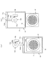
また、このコーヒー抽出装置2は、ドリップユニット21が駆動ユニット22に取り付けられた際に、その取付け作業を行った者が、ドリップユニット21が適正な状態で取り付けられているか否かを、前面カバー35の状態によって、容易にわかるように構成されている。なお、ドリップユニット21が駆動ユニット22に適正に取り付けられた状態とは、ドリップユニット21の左右のユニットロック部材82、82の上下のロック部82a、82aがいずれも、駆動ユニット22側の対応する係合孔108d、108dに完全に挿入し、係止されることにより、トリップユニット21が駆動ユニット22に完全に装着された状態である(図14(a)参照)。   In addition, the coffee brewing device 2 determines whether or not the person who performed the drip unit 21 when the drip unit 21 is attached to the drive unit 22 is attached in a proper state. According to the state of 35, it is configured to be easily understood. The state in which the drip unit 21 is properly attached to the drive unit 22 means that the upper and lower lock portions 82a and 82a of the left and right unit lock members 82 and 82 of the drip unit 21 correspond to the drive unit 22 side. The trip unit 21 is completely attached to the drive unit 22 by being completely inserted and locked into the engagement holes 108d and 108d (see FIG. 14A).

図13に示すように、前面カバー35は、正面形状がほぼ矩形状に形成されている。また、前面カバー35の背面上端部には、左右端部にそれぞれ、側面形状がC字状の係合凹部35a、35aが設けられており、これらの係合凹部35a、35aが、左右の側壁41、41の内側面から内方にそれぞれ突出する支持凸部41b、41b(図7参照)に回動自在に係合している。さらに、前面カバー35の左右側部の所定位置にはそれぞれ、直角に屈曲して後方に突出するレバーカバー部35b、35bが設けられている。これらのレバーカバー部35b、35bは、前面カバー35が閉鎖したときに、左右の側壁41、41の凹部41a、41aをそれぞれ覆うとともに、取外しレバー84、84の前端部も覆う。また、前面カバー35の背面には、両レバーカバー部35b、35bの付近に、後方に突出する凸部35c、35cが設けられている。   As shown in FIG. 13, the front cover 35 has a substantially rectangular front shape. Further, the front upper end portion of the front cover 35 is provided with engagement concave portions 35a and 35a having C-shaped side surfaces at the left and right end portions, respectively, and these engagement concave portions 35a and 35a are provided on the left and right side walls. 41 and 41 are rotatably engaged with support convex portions 41b and 41b (see FIG. 7) that protrude inward from the inner side surfaces of the inner surfaces. Furthermore, lever cover portions 35b and 35b that are bent at a right angle and protrude rearward are provided at predetermined positions on the left and right side portions of the front cover 35, respectively. These lever cover portions 35b and 35b cover the concave portions 41a and 41a of the left and right side walls 41 and 41, respectively, and also cover the front end portions of the removal levers 84 and 84 when the front cover 35 is closed. Further, on the back surface of the front cover 35, convex portions 35c and 35c protruding rearward are provided in the vicinity of both lever cover portions 35b and 35b.

これらの凸部35c、35cは、両取外しレバー84、84にそれぞれ対応しており、図14(a)に示すように、ドリップユニット21が駆動ユニット22に適正な状態で取り付けられたときには、凸部35cが取外しレバー84の前端部84aの直ぐ下側に位置する。この場合、ドリップユニット21の前面は、垂下する前面カバー35によって、閉鎖される(閉鎖位置)。なお、この場合には、前面カバー35の背面下端部に突設された係止部35dが、フレーム31の底壁43に係合することで、前面カバー35が比較的しっかりと閉鎖した状態に保持される。   These projections 35c and 35c correspond to the two removal levers 84 and 84, respectively, and when the drip unit 21 is attached to the drive unit 22 in an appropriate state as shown in FIG. The portion 35 c is located immediately below the front end portion 84 a of the removal lever 84. In this case, the front surface of the drip unit 21 is closed by the front cover 35 that hangs down (closed position). In this case, the front cover 35 is closed relatively firmly by engaging the locking portion 35d protruding from the lower end of the back surface of the front cover 35 with the bottom wall 43 of the frame 31. Retained.

これに対し、駆動ユニット22に対するドリップユニット21の取り付けが不適正な状態では、図14(b)に示すように、前面カバー35が傾斜し、若干開放した状態となる。このような前面カバー35の状態は、以下のようにして生じる。すなわち、ドリップユニット21の左右のユニットロック部材82の少なくとも一方において、図14(b)に示すように、上下のロック部82a、82aが、駆動ユニット22側の係合孔108d、108dに途中まで挿入され、完全には係止されていない状態では、ユニットロック部材82が、ばね83の付勢力に抗して、上方に若干移動する。これに伴い、ユニットロック部材82の下凸部82eが、取外しレバー84の後端部84bを押し上げる。これにより、取外しレバー84は、支軸44dを中心として回動し、前端部84aが前面カバー35の前記凸部35cの上面よりも下方に若干移動する。そのため、前面カバー35の凸部35cが取外しレバー84の前端に当接し、前面カバー35の完全な閉鎖が阻止される。それにより、上述したように、前面カバー35は、若干開放した状態となる。   On the other hand, when the drip unit 21 is not properly attached to the drive unit 22, the front cover 35 is inclined and slightly opened as shown in FIG. 14 (b). Such a state of the front cover 35 occurs as follows. That is, in at least one of the left and right unit lock members 82 of the drip unit 21, as shown in FIG. 14 (b), the upper and lower lock portions 82a and 82a are halfway in the engagement holes 108d and 108d on the drive unit 22 side. In a state where the unit lock member 82 is inserted and not completely locked, the unit lock member 82 slightly moves upward against the urging force of the spring 83. Accordingly, the lower convex portion 82e of the unit lock member 82 pushes up the rear end portion 84b of the removal lever 84. As a result, the removal lever 84 rotates about the support shaft 44d, and the front end portion 84a moves slightly below the upper surface of the convex portion 35c of the front cover 35. Therefore, the convex portion 35c of the front cover 35 abuts on the front end of the removal lever 84, and the front cover 35 is prevented from being completely closed. Thereby, as described above, the front cover 35 is slightly opened.

以上のように、駆動ユニット22に対するドリップユニット21の取付けが不適正である場合には、前面カバー35が若干開放した状態となるので、その取付け作業を行った者は、ドリップユニット21が適正に取り付けられているか否かを、容易に知ることができる。したがって、ドリップユニット21の不適正な取付けに起因する不具合、例えば、ドリップユニット21側の従動ジョイントギヤ76Aと、駆動ユニット22側の駆動ジョイントギヤ134との不十分な噛合いによるドリップユニット21の動作不良や、ドリップユニット21側のジョイントホース40と駆動ユニット22側のジョイントホース120との接続不良による水漏れなどを防止することができる。   As described above, when the drip unit 21 is not properly attached to the drive unit 22, the front cover 35 is slightly opened. Whether it is attached or not can be easily known. Therefore, the malfunction of the drip unit 21 due to improper attachment of the drip unit 21, for example, the operation of the drip unit 21 due to insufficient engagement between the driven joint gear 76A on the drip unit 21 side and the driving joint gear 134 on the driving unit 22 side. It is possible to prevent water leakage or the like due to defects or poor connection between the joint hose 40 on the drip unit 21 side and the joint hose 120 on the drive unit 22 side.

次に、シリンダホルダ24内に収容されたシリンダ23を把持するシリンダキャッチャ34について説明する。図7および同図(b)のB−B線で切断した図15(a)に示すように、シリンダキャッチャ34は、平面形状が前方に開放するコ字状の支持部材91と、この支持部材91の左右の前端部にそれぞれ固定された2つの把持部材92、92で構成されている。支持部材91は、板ばねから成り、左右方向に所定長さ延びる基部91aと、この基部91aの左右端部においてそれぞれ直角に屈曲し、前方に所定長さ延びる左右2つのアーム部91b、91bとで構成されている。基部91aは、背壁42の内側面にねじ止めされている。そして、両アーム部91b、91bの前端部に、前記把持部材92、92が固定されている。両把持部材92、92は、互いに対向し、それらの対向面が凸状に形成されている。   Next, the cylinder catcher 34 that holds the cylinder 23 accommodated in the cylinder holder 24 will be described. As shown in FIG. 7A and FIG. 15A cut along the line BB in FIG. 7B, the cylinder catcher 34 includes a U-shaped support member 91 having a planar shape opened forward, and the support member. It is composed of two gripping members 92 and 92 fixed to the left and right front end portions of 91, respectively. The support member 91 is made of a leaf spring, and has a base portion 91a extending a predetermined length in the left-right direction and two left and right arm portions 91b, 91b extending at a right angle at the left and right ends of the base portion 91a and extending a predetermined length forward. It consists of The base 91a is screwed to the inner side surface of the back wall 42. And the said holding members 92 and 92 are being fixed to the front-end part of both arm parts 91b and 91b. Both the gripping members 92 and 92 are opposed to each other, and their facing surfaces are formed in a convex shape.

このように構成されたシリンダキャッチャ34により、シリンダホルダ24のシリンダ収容部24aに収容されたシリンダ23は、支持部材91のばね力により、左右の把持部材92、92によって左右からしっかりと挟持される。   With the cylinder catcher 34 configured in this manner, the cylinder 23 accommodated in the cylinder accommodating portion 24a of the cylinder holder 24 is firmly clamped from the left and right by the left and right gripping members 92, 92 by the spring force of the support member 91. .

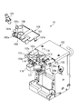
次に、図16〜25を参照しながら、駆動ユニット22について説明する。駆動ユニット22は、その外殻を構成するケース101と、このケース101の前面上部に前方に突出するように設けられたシリンダヘッドカバー100とを備えている。ケース101は、所定形状の複数の金属板を互いに組み付け、ねじ止めすることなどにより、ボックス状に形成されている。   Next, the drive unit 22 will be described with reference to FIGS. The drive unit 22 includes a case 101 that constitutes an outer shell thereof, and a cylinder head cover 100 that is provided on the front upper portion of the case 101 so as to protrude forward. The case 101 is formed in a box shape by assembling a plurality of metal plates having a predetermined shape and screwing them together.

図16(a)に示すように、ケース101の前面を構成する前壁108には、その下半部に、大きく開放した開口部108aが形成されており、前述したスクレーパ33が、後方に駆動された際に、この開口部108aを介して、駆動ユニット22内に収容される。また、前壁108の左右端部の所定位置には、上下2つずつの係合孔108d(係合部)およびガイド孔108eが左右対称に設けられている。前述したように、係合孔108dにはドリップユニット21側のロック部82aが係止され、ガイド孔108eにはドリップユニット21側のガイド突部44hが挿入される。   As shown in FIG. 16 (a), the front wall 108 constituting the front surface of the case 101 is formed with a large open opening 108a in the lower half thereof, and the scraper 33 described above is driven rearward. When this is done, the drive unit 22 is accommodated through the opening 108a. In addition, at a predetermined position on the left and right end portions of the front wall 108, two upper and lower engagement holes 108d (engagement portions) and guide holes 108e are provided symmetrically. As described above, the lock portion 82a on the drip unit 21 side is engaged with the engagement hole 108d, and the guide protrusion 44h on the drip unit 21 side is inserted into the guide hole 108e.

シリンダヘッドカバー100は、互いに左右方向に間隔を隔てて、ケース101の前側上部の左右端部に、前方に突出するように設けられた左右一対のシリンダヘッドサポート103、103と、これらの間に着脱自在に取り付けられたカバー本体102などで構成されている。図21に示すように、各シリンダヘッドサポート103は、正面形状が逆U字状に形成され、上面および外側面の所定位置には、カバー本体102の後述する係合爪102bに係合する係合孔103a、103bがそれぞれ形成されている。また、各シリンダヘッドサポート103の内側面には、前後方向に延び、後述するシリンダヘッド111のヘッドガイドシャフト114の前後方向の移動を許容するガイド孔103cが形成されている。さらに、各シリンダヘッドサポート103の上面には、上記ガイド孔103cの前端部から連なる開口部103dが形成されている。この開口部103dは、前後方向の幅がガイドシャフト114の径よりも大きくなっている。   The cylinder head cover 100 is provided with a pair of left and right cylinder head supports 103 and 103 provided at the left and right ends of the upper front portion of the case 101 so as to protrude forward, and spaced apart from each other in the left and right direction. The cover body 102 is freely attached and the like. As shown in FIG. 21, each cylinder head support 103 is formed in an inverted U shape on the front surface, and is engaged with an engaging claw 102 b (described later) of the cover main body 102 at a predetermined position on the upper surface and the outer surface. Joint holes 103a and 103b are respectively formed. In addition, a guide hole 103c that extends in the front-rear direction and allows a head guide shaft 114 of a cylinder head 111 described later to move in the front-rear direction is formed on the inner side surface of each cylinder head support 103. Further, an opening 103d is formed on the upper surface of each cylinder head support 103 from the front end of the guide hole 103c. The opening 103 d has a width in the front-rear direction that is larger than the diameter of the guide shaft 114.

カバー本体102は、平面形状がほぼ矩形状に形成されており、上面の所定位置には、いずれも上下方向に貫通しかつ上方に突出した原料シュート104および湯気抜きダクト106がカバー本体102と一体に設けられている。また、カバー本体102には、上下方向に貫通した取付孔102aに、給湯ノズル105が着脱自在に取り付けられている。なお、原料シュート104には、ミル12のシュート12a(図1参照)が接続され、湯気抜きダクト106には、湯気抜き用のホース(図示せず)が接続され、さらに、給湯ノズル105には、給湯チューブ13a(図1参照)が接続されている。   The cover main body 102 is formed in a substantially rectangular shape in plan view, and a raw material chute 104 and a steam venting duct 106 that penetrate vertically and project upward are integrally formed with the cover main body 102 at predetermined positions on the upper surface. Is provided. In addition, a hot water supply nozzle 105 is detachably attached to the cover main body 102 in an attachment hole 102a penetrating in the vertical direction. A chute 12a (see FIG. 1) of the mill 12 is connected to the raw material chute 104, a hose (not shown) for steam removal is connected to the steam vent duct 106, and a hot water supply nozzle 105 is connected to the steam chute 105. The hot water supply tube 13a (see FIG. 1) is connected.

また、カバー本体102の左右端部には、下方に若干突出し、鉤状に形成された左右2つの係止爪102b、102bが設けられている。このように構成されたカバー本体102は、各係止爪102bが、対応するシリンダヘッドサポート103の上面の係合孔103aに挿入するとともに、外側面の係合孔103bに内方からスナップ嵌めで係合することにより、両シリンダヘッドサポート103、103間にしっかりと取り付けられる。   The left and right end portions of the cover body 102 are provided with two left and right engaging claws 102b and 102b that protrude slightly downward and are formed in a hook shape. In the cover body 102 configured in this manner, each locking claw 102b is inserted into the engagement hole 103a on the upper surface of the corresponding cylinder head support 103, and is snap-fitted into the engagement hole 103b on the outer surface from the inside. By being engaged, the cylinder head supports 103 and 103 are firmly attached.

一方、カバー本体102をシリンダヘッドサポート103、103から取り外す場合には、左側の係止爪102bから上方に若干延びる操作部102cを左方に押すことによって、左側および右側の係止爪102b、102bを、シリンダヘッドサポート103の係止孔103bから順に外し、それにより、カバー本体102を容易に取り外すことができる。このように、カバー本体102が、工具などを用いることなく容易に取り外せることにより、カバー本体102自体を丸洗いすることが可能であり、また、シリンダヘッドカバー100の内部に、上方から容易にアクセスできることで、そのメンテナンス性や清掃性を向上させることができる。   On the other hand, when removing the cover main body 102 from the cylinder head supports 103, 103, the left and right engaging claws 102b, 102b are pushed by pushing the operation portion 102c slightly extending upward from the left engaging claws 102b to the left. Are sequentially removed from the locking holes 103b of the cylinder head support 103, whereby the cover body 102 can be easily removed. As described above, the cover main body 102 can be easily removed without using a tool or the like, so that the cover main body 102 itself can be washed, and the inside of the cylinder head cover 100 can be easily accessed from above. The maintainability and cleanability can be improved.

上記のように構成されたシリンダヘッドカバー100の内側には、シリンダ23の上面を開閉するシリンダヘッド111が前後方向にスライド自在に設けられている。   A cylinder head 111 that opens and closes the upper surface of the cylinder 23 is slidably provided in the front-rear direction inside the cylinder head cover 100 configured as described above.

図22は、シリンダヘッド111およびその周囲を示している。同図(a)に示すように、シリンダヘッド111は、平面形状がシリンダ23の上面よりも大きい円形状に形成されている。シリンダヘッド111の下面全体には、下面が平らな円形のパッキン112が設けられ、このパッキン112に、エア供給口112a(図23(b)参照)が設けられている。また、シリンダヘッド111の上部は、円錐台状に形成されており、その上端部には、外部からシリンダヘッド111内を通り、上記パッキン112のエア供給口112aを介して、下方にエアを供給するためのゴム製のエア供給管113が接続されている。また、シリンダヘッド111の上端部には、シリンダヘッド111の外径よりも長く、左右方向(図22(a)では上下方向)に延びるヘッドガイドシャフト114が設けられている。   FIG. 22 shows the cylinder head 111 and its surroundings. As shown in FIG. 5A, the cylinder head 111 is formed in a circular shape whose planar shape is larger than the upper surface of the cylinder 23. A circular packing 112 having a flat bottom surface is provided on the entire bottom surface of the cylinder head 111, and an air supply port 112a (see FIG. 23B) is provided in the packing 112. The upper part of the cylinder head 111 is formed in a truncated cone shape, and air is supplied to the upper end of the cylinder head 111 from outside through the air supply port 112a of the packing 112 from outside. A rubber air supply pipe 113 is connected for this purpose. Further, a head guide shaft 114 that is longer than the outer diameter of the cylinder head 111 and extends in the left-right direction (vertical direction in FIG. 22A) is provided at the upper end of the cylinder head 111.

また、シリンダヘッド111には、連結部材115を介して、前後方向にスライド自在のスライダ116が連結されている。連結部材115は、平面形状が前方に開放したほぼコ字状に形成され、左右の前端部がそれぞれ連結軸115aを介して、ヘッドガイドシャフト114の真下において、シリンダヘッド111に回動自在に連結されている。スライダ116は、前後方向に延び、前端部が連結部材115の後端部に連結軸116aを介して、回動自在に連結されている。また、スライダ116の後端部には、左右方向に延びる長孔116bが形成され、この長孔116bに、後述するスクレーパ・シリンダヘッド駆動機構123が係合している。そして、シリンダヘッド111およびスライダ116は、所定形状のヘッドガイド部材117によって案内されながら、前後方向にスライドする。   Further, a slider 116 slidable in the front-rear direction is connected to the cylinder head 111 via a connecting member 115. The connecting member 115 is formed in a substantially U-shape with a planar shape opened to the front, and the left and right front end portions are rotatably connected to the cylinder head 111 via the connecting shaft 115a directly below the head guide shaft 114, respectively. Has been. The slider 116 extends in the front-rear direction, and a front end portion thereof is rotatably connected to a rear end portion of the connecting member 115 via a connecting shaft 116a. A long hole 116b extending in the left-right direction is formed at the rear end of the slider 116, and a scraper / cylinder head driving mechanism 123, which will be described later, is engaged with the long hole 116b. The cylinder head 111 and the slider 116 slide in the front-rear direction while being guided by the head guide member 117 having a predetermined shape.

ヘッドガイド部材117は、前述した左右のシリンダヘッドサポート103、103間に固定されている。図22に示すように、このヘッドガイド部材117は、上記スライダ116をスライド自在に支持するスライダ支持部117aと、このスライダ支持部117aからシリンダヘッド111の左右の側方を通って前方に延び、前記ヘッドガイドシャフト114を載置した状態で支持する左右2つのシャフト支持部117b、117bとを有している。   The head guide member 117 is fixed between the left and right cylinder head supports 103, 103 described above. As shown in FIG. 22, the head guide member 117 includes a slider support portion 117a that slidably supports the slider 116, and extends forward from the slider support portion 117a through the left and right sides of the cylinder head 111. It has two left and right shaft support portions 117b and 117b that support the head guide shaft 114 in a state where it is placed.

また、シリンダヘッド111の前部には、補助原料シュート118が着脱自在に取り付けられている。この補助原料シュート118は、シリンダヘッド111が待機位置に位置するときに、前記カバー本体102の原料シュート104とシリンダ23の間に位置し、原料シュート104で案内された原料を、さらにシリンダ23に案内するものである。補助原料シュート118は、上下方向に貫通し、上面が前記カバー本体102の原料シュート104の底面よりも若干大きい筒状に形成されている。補助原料シュート118の背面には、後方に延びる取付けアーム119が一体に設けられている。この取付けアーム119は、上下方向に延び、下端部が鉤状に形成された左右一対の係止爪119a、119aを有しており、両係止爪119a、119aが互いに上下方向の中央で連結されている。このように構成された補助原料シュート118は、両係止爪119a、119aの下端部が、シリンダヘッド111の上面前部のシュート取付部111aをスナップ嵌めで左右から挟持することにより、シリンダヘッド111にしっかりと取り付けられる。   An auxiliary material chute 118 is detachably attached to the front portion of the cylinder head 111. The auxiliary material chute 118 is located between the material chute 104 of the cover main body 102 and the cylinder 23 when the cylinder head 111 is located at the standby position, and the material guided by the material chute 104 is further transferred to the cylinder 23. It is a guide. The auxiliary raw material chute 118 penetrates in the vertical direction and is formed in a cylindrical shape whose upper surface is slightly larger than the bottom surface of the raw material chute 104 of the cover body 102. A mounting arm 119 extending rearward is integrally provided on the back surface of the auxiliary material chute 118. The mounting arm 119 has a pair of left and right locking claws 119a and 119a extending in the vertical direction and having a lower end formed in a bowl shape, and the both locking claws 119a and 119a are connected to each other in the vertical center. Has been. The auxiliary raw material chute 118 configured as described above is configured such that the lower end portions of the two locking claws 119a and 119a sandwich the chute mounting portion 111a at the front upper surface of the cylinder head 111 from the left and right by snap fitting, thereby It can be securely attached to.

一方、補助原料シュート118をシリンダヘッド111から取り外す場合には、両係止爪119a、119aの上端部同士を摘み、下端部間を広げることによって、容易に取り外すことができる。このように、補助原料シュート118が、工具などを用いることなく容易に取り外せることにより、補助原料シュート118自体を丸洗いすることが可能である。   On the other hand, when the auxiliary material chute 118 is removed from the cylinder head 111, it can be easily removed by picking the upper ends of the locking claws 119a and 119a and widening the lower ends. Thus, the auxiliary material chute 118 can be easily removed without using a tool or the like, so that the auxiliary material chute 118 itself can be washed.

また、シリンダヘッド111は、図22(c)に示すように、連結軸116aを中心として、前方に回動し(例えば45度)、シリンダヘッド111の下面、すなわちパッキン112を前方に向けることが可能である。この場合、ヘッドガイドシャフト114は、左右のシリンダヘッドサポート103、103のガイド孔103cから、その前側上部の開口部103dを介して、上方に引き出され、それにより、シリンダヘッド111の下面が前方に向けられる。このように、シリンダヘッド111が、その下面を前方に向けられるように構成されているため、シリンダヘッド111のメンテナンス性や清掃性を向上させることができる。   Further, as shown in FIG. 22C, the cylinder head 111 rotates forward (for example, 45 degrees) about the connecting shaft 116a, and the lower surface of the cylinder head 111, that is, the packing 112 may be directed forward. Is possible. In this case, the head guide shaft 114 is drawn upward from the guide holes 103c of the left and right cylinder head supports 103, 103 via the opening 103d at the front upper portion thereof, whereby the lower surface of the cylinder head 111 is moved forward. Directed. Thus, since the cylinder head 111 is configured such that its lower surface is directed forward, the maintenance performance and cleaning performance of the cylinder head 111 can be improved.

次に、駆動ユニット22のケース101内の構造について説明する。図16〜20に示すように、ケース101には、前述したドリップユニット21のカム円板55を駆動するカム駆動機構121(駆動機構)と、後述する複数のピンチ8を駆動するピンチ駆動機構122と、スクレーパ33およびシリンダヘッド111を駆動するスクレーパ・シリンダヘッド駆動機構123(駆動機構)と、シリンダ23にエアを供給するエアポンプ124などが内蔵されている。   Next, the structure in the case 101 of the drive unit 22 will be described. As shown in FIGS. 16 to 20, the case 101 includes a cam drive mechanism 121 (drive mechanism) that drives the cam disk 55 of the drip unit 21 and a pinch drive mechanism 122 that drives a plurality of pinches 8 described later. And a scraper / cylinder head driving mechanism 123 (driving mechanism) for driving the scraper 33 and the cylinder head 111, an air pump 124 for supplying air to the cylinder 23, and the like.

カム駆動機構121は、DCモータから成る第1モータ131と、この第1モータ131に接続されるとともに、左右方向に延びかつ両端部が外部に突出する出力軸132aを有するギヤボックス132と、出力軸132aの左端部に固定された出力ギヤ133と、この出力ギヤ133に噛み合うとともに、ドリップユニット21側の従動ジョイントギヤ76に噛み合う駆動ジョイントギヤ134とを備えている。なお、上記のギヤボックス132や駆動ジョイントギヤ134などは、所定形状の支持プレート(図示せず)に適宜、取り付けられている。   The cam drive mechanism 121 includes a first motor 131 formed of a DC motor, a gear box 132 that is connected to the first motor 131, has an output shaft 132a that extends in the left-right direction, and has both ends projecting to the outside. An output gear 133 fixed to the left end of the shaft 132a and a drive joint gear 134 that meshes with the output gear 133 and meshes with the driven joint gear 76 on the drip unit 21 side are provided. The gear box 132 and the drive joint gear 134 are appropriately attached to a support plate (not shown) having a predetermined shape.

また、出力ギヤ133の付近には、カム円板55の回転角度を制御するためのモードスイッチ136が設けられている。このモードスイッチ136は、中間ギヤ137を介して出力ギヤ133に噛み合うとともに、カム円板55と同期して、等角度で回転するスイッチギヤ136aを有している。モードスイッチ136は、スイッチギヤ136aが複数の所定の回転角度においてON状態になる複数のモードを有しており、制御装置7が、それらのモードに応じて、カム円板55の回転角度を識別する。   A mode switch 136 for controlling the rotation angle of the cam disk 55 is provided near the output gear 133. The mode switch 136 has a switch gear 136 a that meshes with the output gear 133 via the intermediate gear 137 and rotates at an equal angle in synchronization with the cam disk 55. The mode switch 136 has a plurality of modes in which the switch gear 136a is turned on at a plurality of predetermined rotation angles, and the control device 7 identifies the rotation angle of the cam disk 55 according to those modes. To do.

ピンチ駆動機構122は、コーヒー抽出時に、コーヒーやエアを搬送するための搬送チューブ9の複数の所定個所を開閉するためのピンチ8を駆動するものである。ここでまず、図1を参照して、搬送チューブ9およびピンチ8の配置関係および構成について簡単に説明する。同図に示すように、搬送チューブ9は、エアポンプ124とシリンダヘッド111の間に接続された第1エア搬送チューブ9Aと、エアポンプ124と駆動ユニット22側のジョイントホース120の間に接続された第2エア搬送チューブ9Bと、ジョイントホース120に接続された飲料搬送チューブ9Cとで構成されている。これらの搬送チューブ9A〜9Cはいずれも、ゴムなどの弾性材で構成されている。上記ジョイントホース120は、駆動ユニット22の前側の右下端部に設けられており、ドリップユニット21が駆動ユニット22に取り付けられた状態において、ドリップユニット21側のジョイントホース40に接続される。   The pinch drive mechanism 122 drives the pinch 8 for opening and closing a plurality of predetermined portions of the transport tube 9 for transporting coffee and air during coffee extraction. Here, first, with reference to FIG. 1, the arrangement | positioning relationship and structure of the conveyance tube 9 and the pinch 8 are demonstrated easily. As shown in the figure, the transfer tube 9 includes a first air transfer tube 9A connected between the air pump 124 and the cylinder head 111, and a first hose 120 connected between the air pump 124 and the joint hose 120 on the drive unit 22 side. It is comprised by 2 air conveyance tube 9B and the drink conveyance tube 9C connected to the joint hose 120. FIG. These transfer tubes 9A to 9C are all made of an elastic material such as rubber. The joint hose 120 is provided at the lower right end on the front side of the drive unit 22, and is connected to the joint hose 40 on the drip unit 21 side when the drip unit 21 is attached to the drive unit 22.

また、ピンチ8は、上記搬送チューブ9A〜9Cの途中にそれぞれ取り付けられた3つのピンチ8、具体的には、第1エアピンチ8A、第2エアピンチ8Bおよび飲料ピンチ8Cで構成されている。これらのピンチ8A〜8Cは、同じものである。図16(b)および図17(b)に示すように、各ピンチ8は、自身が取り付けられた搬送チューブ9の部分を保持するチューブホルダ141と、チューブホルダ141に回動自在に取り付けられ、これと協働して搬送チューブ9を押し潰し、閉鎖するためのピンチ本体142と、このピンチ本体142の搬送チューブ9と反対側に回転自在に設けられ、ピンチ本体142を搬送チューブ9側に押圧するための所定形状のカム143とで構成されている。   Moreover, the pinch 8 is comprised by the three pinches 8 each attached in the middle of the said conveyance tubes 9A-9C, specifically, the 1st air pinch 8A, the 2nd air pinch 8B, and the drink pinch 8C. These pinches 8A to 8C are the same. As shown in FIGS. 16 (b) and 17 (b), each pinch 8 is rotatably attached to the tube holder 141 that holds the portion of the transport tube 9 to which the pinch 8 is attached, and the tube holder 141. In cooperation with this, a pinch main body 142 for crushing and closing the transport tube 9 and a pinch main body 142 that is rotatably provided on the opposite side of the transport tube 9 and pressing the pinch main body 142 toward the transport tube 9 side are provided. And a cam 143 having a predetermined shape.

このように構成されたピンチ8A〜8Cは、第1および第2エアピンチ8A、8Bが、図16(b)に示すように、左右に隣接して配置され、飲料ピンチ8Cが、図17(b)に示すように、第2エアピンチ8Bの後方にこれに対向するように配置されている。なお、これらのピンチ8A〜8Cでは、カム143が共通化されている。   In the pinches 8A to 8C configured as described above, the first and second air pinches 8A and 8B are arranged adjacent to each other as shown in FIG. 16B, and the beverage pinch 8C is formed as shown in FIG. ), The second air pinch 8B is disposed behind the second air pinch 8B so as to oppose it. In these pinches 8A to 8C, the cam 143 is shared.

図16および図19に示すように、ピンチ駆動機構122は、前述したカム駆動機構121と共通の第1モータ131およびギヤボックス132と、その出力軸132aの右端部に固定された出力ギヤ145と、ピンチ8のカム143の回転シャフト146に固定された駆動ギヤ147と、上記出力ギヤ145および駆動ギヤ147にそれぞれ噛み合う2つのギヤ部を有する中間ギヤ148とを備えている。   As shown in FIGS. 16 and 19, the pinch drive mechanism 122 includes a first motor 131 and a gear box 132 that are common to the cam drive mechanism 121 described above, and an output gear 145 fixed to the right end of the output shaft 132a. , A drive gear 147 fixed to the rotating shaft 146 of the cam 143 of the pinch 8, and an intermediate gear 148 having two gear portions respectively engaged with the output gear 145 and the drive gear 147.

上述したように、カム駆動機構121およびピンチ駆動機構122は、第1モータ131を共通の駆動源とし、前者121によるカム円板55、フィルタブロック32、シリンダヘッドロック部材57および廃液チューブピンチ部材58と、後者122による3つのピンチ8A〜8Cとを、相互に連係するように駆動する。これにより、コーヒーの抽出時において、シリンダ23の上面および下面の開閉、廃液チューブピンチ部材58による廃液チューブ50の開閉、ならびにピンチ8A〜8Cによる搬送チューブ9A〜9Cの開閉を、効率良くかつ適切に行うことができる。   As described above, the cam drive mechanism 121 and the pinch drive mechanism 122 use the first motor 131 as a common drive source, and the cam disk 55, the filter block 32, the cylinder head lock member 57, and the waste tube pinch member 58 by the former 121. And the three pinches 8A to 8C by the latter 122 are driven so as to be linked to each other. Thereby, when coffee is extracted, the upper and lower surfaces of the cylinder 23 are opened and closed, the waste tube 50 is opened and closed by the waste tube pinch member 58, and the transport tubes 9A to 9C are opened and closed by the pinches 8A to 8C. It can be carried out.

図23は、スクレーパ・シリンダヘッド駆動機構123およびその周囲を示している。同図に示すように、スクレーパ・シリンダヘッド駆動機構123は、DCモータから成る第2モータ151と、この第2モータ151に接続されるとともに、上下方向に延びかつ両端部が外部に突出した出力軸152aを有するギヤボックス152と、出力軸152aの上下端部にそれぞれ設けられたシリンダヘッド駆動部153およびスクレーパ駆動部154などで構成されている。   FIG. 23 shows the scraper / cylinder head driving mechanism 123 and its surroundings. As shown in the figure, the scraper / cylinder head drive mechanism 123 is connected to a second motor 151 composed of a DC motor, and to the second motor 151. The output extends in the vertical direction and projects at both ends. A gear box 152 having a shaft 152a, and a cylinder head driving unit 153 and a scraper driving unit 154 provided at the upper and lower ends of the output shaft 152a, respectively.

図23および図24に示すように、シリンダヘッド駆動部153は、平面形状が円形に形成され、出力軸152aの回転に伴って、所定の一方向にのみ回転可能なワンウェイクラッチで構成されている。シリンダヘッド駆動部153の上面周縁部には、上方に突出した係合凸部153aが設けられており、この係合凸部153aが、シリンダヘッド111に連結されたスライダ116の長孔116bに摺動自在に係合している。したがって、シリンダヘッド駆動部153が、図24(a)に示す待機位置から180度回転することにより、同図(b)に示すように、スライダ116が前方(同図の下方)にスライドし、それにより、シリンダヘッド111が前方のシリンダ閉鎖位置に移動する。   As shown in FIGS. 23 and 24, the cylinder head drive unit 153 is formed of a one-way clutch that is formed in a circular shape in plan view and can rotate only in a predetermined direction as the output shaft 152a rotates. . An engagement protrusion 153 a protruding upward is provided at the peripheral edge of the upper surface of the cylinder head drive unit 153, and the engagement protrusion 153 a is slid into a long hole 116 b of the slider 116 connected to the cylinder head 111. It engages freely. Therefore, when the cylinder head drive unit 153 rotates 180 degrees from the standby position shown in FIG. 24A, the slider 116 slides forward (downward in the figure) as shown in FIG. Thereby, the cylinder head 111 moves to the front cylinder closed position.

また、上記シリンダヘッド駆動部153の左右には、シリンダヘッド駆動部153の回転位置を検出することによってシリンダヘッド111の位置を検出するための2つのマイクロスイッチ155、155が配置されている。各マイクロスイッチ155は、常時、スイッチレバー155aの先端部がシリンダヘッド駆動部153の側面に当接しており、その側面の所定位置に設けられた凹部153bにスイッチレバー155aの先端部が係合することによって、マイクロスイッチ155のON/OFF状態が切り換わる。   Two micro switches 155 and 155 for detecting the position of the cylinder head 111 by detecting the rotational position of the cylinder head drive unit 153 are arranged on the left and right sides of the cylinder head drive unit 153. In each micro switch 155, the tip of the switch lever 155a is always in contact with the side surface of the cylinder head drive unit 153, and the tip of the switch lever 155a engages with a recess 153b provided at a predetermined position on the side surface. As a result, the ON / OFF state of the microswitch 155 is switched.

一方、スクレーパ駆動部154は、上記シリンダヘッド駆動部153と反対方向にのみ回転可能なワンウェイクラッチで構成されている。このスクレーパ駆動部154の下部には、水平に所定長さ延びるアーム部154aが設けられており、その先端部には、下方に延びる係合凸部154bが設けられている。この係合凸部154bは、スクレーパ33のサポート77の溝部77aに摺動自在に係合している。なお、ドリップユニット21を駆動ユニット22に取り付ける際には、上記係合凸部154bが、スクレーパ33の開放部77bを介して、溝部77aに挿入され、逆に、ドリップユニット21を駆動ユニット22から取り外す際には、溝部77aに係合する係合凸部154bが、開放部77bを介して、溝部77aから離脱する。   On the other hand, the scraper drive unit 154 is configured by a one-way clutch that can rotate only in the direction opposite to the cylinder head drive unit 153. An arm portion 154a extending horizontally for a predetermined length is provided at the lower portion of the scraper driving portion 154, and an engaging convex portion 154b extending downward is provided at a tip portion thereof. The engaging convex portion 154b is slidably engaged with the groove portion 77a of the support 77 of the scraper 33. When the drip unit 21 is attached to the drive unit 22, the engaging convex portion 154 b is inserted into the groove portion 77 a through the opening portion 77 b of the scraper 33, and conversely, the drip unit 21 is removed from the drive unit 22. When removing, the engaging convex part 154b engaged with the groove part 77a is detached from the groove part 77a via the opening part 77b.

また、スクレーパ駆動部154の右方には、スクレーパ駆動部154の回転位置を検出することによってスクレーパ33の位置を検出するためのマイクロスイッチ156が配置されている。図25に示すように、マイクロスイッチ156は、常時、スイッチレバー156aの先端部がスクレーパ駆動部154の側面に当接しており、その側面の所定位置に設けられた凹部154cにスイッチレバー156aの先端部が係合することによって、マイクロスイッチ156のON/OFF状態が切り換わる。   A micro switch 156 for detecting the position of the scraper 33 by detecting the rotational position of the scraper drive unit 154 is disposed on the right side of the scraper drive unit 154. As shown in FIG. 25, in the micro switch 156, the tip end portion of the switch lever 156a is always in contact with the side surface of the scraper driving portion 154, and the tip end of the switch lever 156a is in a recess 154c provided at a predetermined position on the side surface. When the parts are engaged, the ON / OFF state of the micro switch 156 is switched.

上記のスクレーパ駆動部154が、図25(a)に示す待機位置から180度回転することにより、同図(b)に示すように、スクレーパ33が後方(同図の上方)の抽出滓排出位置にスライドする。それにより、フィルタブロック32上の抽出滓は、スクレーパ本体78によって後方に掻き取られ、駆動ユニット22の下部に設けられた滓シュート161を介して、下方の滓バケツB(図1参照)に排出される。   When the scraper driving unit 154 rotates 180 degrees from the standby position shown in FIG. 25A, the scraper 33 is located behind (upward in FIG. 25) as shown in FIG. 25B. Slide to. As a result, the extracted soot on the filter block 32 is scraped back by the scraper body 78 and discharged into the lower soot bucket B (see FIG. 1) via the soot chute 161 provided at the lower part of the drive unit 22. Is done.

滓シュート161は、図4および図16(a)に示すように、ケース101内から前壁108の開口部108aを介して前方に若干突出し、平面形状が後方に開放したコ字状の枠部162と、ケース101内にかつ枠部162の内側に設けられ、駆動ユニット22の下部に配置されたエアポンプ124などの機器の前方および上方を覆うカバー163とで構成されている。枠部162のケース101内の左右上端部にはそれぞれ、スクレーパ33を前後方向にスライドさせる際に、これを案内するガイドレール162aが設けられている。また、カバー163は、前カバー部163aと、この前カバー部163aの上端部に連なり、後ろ上がりに傾斜して後方に延びる上カバー部163bとで構成されている。このように構成された枠部162およびカバー163により、コーヒー抽出装置2のほぼ中央部に、滓シュート161が構成される。   As shown in FIGS. 4 and 16 (a), the scissors chute 161 slightly protrudes forward from the inside of the case 101 through the opening 108a of the front wall 108, and has a U-shaped frame portion whose planar shape is open to the rear. 162 and a cover 163 that is provided in the case 101 and inside the frame portion 162 and covers the front and upper sides of devices such as the air pump 124 disposed at the lower part of the drive unit 22. Guide rails 162a for guiding the scraper 33 when the scraper 33 is slid in the front-rear direction are provided on the left and right upper ends of the case portion 101 of the frame portion 162, respectively. Further, the cover 163 includes a front cover portion 163a and an upper cover portion 163b that is connected to the upper end portion of the front cover portion 163a, inclines backward and extends rearward. The frame portion 162 and the cover 163 configured as described above constitute a straw chute 161 at a substantially central portion of the coffee extraction device 2.

また、エアポンプ124は、図16〜図19に示すように、モータ124aと、これによって駆動されるポンプ本体124bと、外気から塵やゴミなどを除去するための吸気フィルタ124cなどで構成されている。ポンプ本体124bは、吸気チューブ125Aを介して、吸気フィルタ124cに接続されるとともに、排気チューブ125Bを介して、前記第1および第2エア搬送チューブ9Aおよび9Bに接続されている。したがって、モータ124aでポンプ本体124bが駆動されると、外部のエアが、吸気フィルタ124cから吸気チューブ125Aを介してポンプ本体124bに吸い込まれ、その吸い込まれたエアが、排気チューブ125Bを介して、第1および第2エア搬送チューブ9Aおよび9Bに圧送される。   As shown in FIGS. 16 to 19, the air pump 124 includes a motor 124a, a pump body 124b driven by the motor 124a, an intake filter 124c for removing dust and dirt from the outside air, and the like. . The pump body 124b is connected to the intake filter 124c via the intake tube 125A, and is connected to the first and second air transfer tubes 9A and 9B via the exhaust tube 125B. Therefore, when the pump body 124b is driven by the motor 124a, external air is sucked into the pump body 124b from the intake filter 124c via the intake tube 125A, and the sucked air is discharged via the exhaust tube 125B. The first and second air transfer tubes 9A and 9B are pumped.

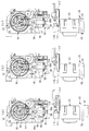
次に、以上のように構成されたコーヒー抽出装置2の動作について、その一連の動作を順に示す図26〜図28を参照しながら説明する。なお、これらの図においては、上段にカム円板55の回転動作を中心に示すものとし、下段にフィルタブロック32、シリンダヘッド111およびスクレーパ33の動作を中心に示すものとする。   Next, the operation of the coffee brewing apparatus 2 configured as described above will be described with reference to FIGS. 26 to 28 showing a series of operations in order. In these figures, the rotation of the cam disk 55 is mainly shown in the upper stage, and the operations of the filter block 32, the cylinder head 111, and the scraper 33 are mainly shown in the lower stage.

図26(a)は、待機状態を示している。この待機状態では、カム円板55、フィルタブロック32、スクレーパ33およびシリンダヘッド111が、それぞれの待機位置に位置するとともに、シリンダ23の上面および下面がいずれも開放されている。また、この待機位置では、補助原料シュート118が、カバー本体102の原料シュート104の真下に位置している。さらに、待機状態では、図29の(1)に示すように、第1エアピンチ8A、第2エアピンチ8Bおよび飲料ピンチ8Cはいずれも開放状態であり、したがって、ピンチ8A〜8Cにそれぞれ対応する搬送チューブ9A〜9Cがいずれも開放されている。   FIG. 26A shows a standby state. In this standby state, the cam disk 55, the filter block 32, the scraper 33, and the cylinder head 111 are located at their standby positions, and the upper surface and the lower surface of the cylinder 23 are all open. In this standby position, the auxiliary material chute 118 is positioned directly below the material chute 104 of the cover main body 102. Further, in the standby state, as shown in (1) of FIG. 29, the first air pinch 8A, the second air pinch 8B, and the beverage pinch 8C are all in an open state, and accordingly, the transport tubes corresponding to the pinches 8A to 8C, respectively. 9A to 9C are all open.

この待機状態から、カム駆動機構121の第1モータ131が所定方向に回転することにより、カム円板55が、図26において時計方向に回転する。それにより、カム円板55の第1カム溝53に係合するスライダ56が上昇し、スライダ56に支持されたフィルタブロック32が、スクレーパ33の内側を通って上昇する。またこの場合、スライダ56の上昇途中において、スライダ56の長孔56bの下縁部が、廃液チューブピンチ部材58の係合凸部58aに当接し、その後、スライダ56の上昇に伴って、廃液チューブピンチ部材58も上昇する。そして、同図(b)に示すように、カム円板55が待機位置から約120度回転することにより、フィルタブロック32がシリンダ23の下面に当接した状態でこれをシールする。またこの場合、廃液チューブピンチ部材58が、その押圧部58bと押さえばね59との間で、廃液チューブ50を押し潰すことにより、これを閉鎖する。   From this standby state, the first motor 131 of the cam drive mechanism 121 rotates in a predetermined direction, whereby the cam disk 55 rotates in the clockwise direction in FIG. As a result, the slider 56 engaged with the first cam groove 53 of the cam disk 55 is raised, and the filter block 32 supported by the slider 56 is raised through the inside of the scraper 33. Further, in this case, the lower edge portion of the long hole 56b of the slider 56 abuts on the engaging convex portion 58a of the waste liquid tube pinch member 58 during the upward movement of the slider 56, and then the waste liquid tube is moved along with the upward movement of the slider 56. The pinch member 58 is also raised. Then, as shown in FIG. 5B, the cam disk 55 rotates about 120 degrees from the standby position, thereby sealing the filter block 32 in contact with the lower surface of the cylinder 23. In this case, the waste liquid tube pinch member 58 closes the waste liquid tube 50 by crushing the waste liquid tube 50 between the pressing portion 58 b and the pressing spring 59.

次いで、この状態において、原料供給装置3および給湯装置4からそれぞれ、所定量の原料および湯が、シリンダ23内に供給される。具体的には、原料は、カバー本体102の原料シュート104およびシリンダヘッド111の補助原料シュート118を介して、シリンダ23に供給される。一方、湯は、カバー本体102の給湯ノズル105を介して、シリンダ23に供給される。この原料および湯の供給時には、図29の(2)に示すように、上記待機状態と同様、ピンチ8A〜8Cはいずれも、開放状態である。   Next, in this state, a predetermined amount of raw material and hot water are supplied into the cylinder 23 from the raw material supply device 3 and the hot water supply device 4, respectively. Specifically, the raw material is supplied to the cylinder 23 via the raw material chute 104 of the cover main body 102 and the auxiliary raw material chute 118 of the cylinder head 111. On the other hand, hot water is supplied to the cylinder 23 via the hot water supply nozzle 105 of the cover body 102. At the time of supplying the raw material and hot water, as shown in (2) of FIG. 29, the pinches 8A to 8C are all in an open state as in the standby state.

原料および湯の供給後、カム円板55は、図26(c)に示すように、待機位置から約180度回転したときに、第1モータ131の停止に伴って停止する。この状態では、図29の(3)に示すように、第2エアピンチ8Bのみが開放状態となり、他のピンチ8Aおよび8Cがいずれも閉鎖状態となる。その後、スクレーパ・シリンダヘッド駆動機構123の第2モータ151が所定方向に回転し、シリンダヘッド駆動部153が、待機位置(図24(a)参照)から、180度回転したときに(図24(b)参照)、第2モータ151が停止する。これにより、シリンダヘッド111は、待機位置から前方に移動し、シリンダ23の真上に到達する。この場合、シリンダヘッド111は、その上部のヘッドガイドシャフト114が、ヘッドガイド部材117のシャフト支持部117bの前端よりも前側に移動することにより、図27(a)に示すように、若干下降し、シリンダ23上に載る。そして、この状態において、エアポンプ124が所定時間(例えば数秒)、作動することにより、エアが、第2エア搬送チューブ9Bおよびフィルタブロックチューブ32aを介してフィルタブロック32に送られる。このエアは、フィルタブロック32のフィルタ72を通過し、シリンダ23内の原料および湯を攪拌する。なお、シリンダ23内で発生した湯気は、湯気抜きダクト106を介して、外部に適宜、排出される。   After the supply of the raw material and hot water, the cam disk 55 stops with the stop of the first motor 131 when it rotates about 180 degrees from the standby position, as shown in FIG. In this state, as shown in (3) of FIG. 29, only the second air pinch 8B is in an open state, and the other pinches 8A and 8C are all in a closed state. Thereafter, the second motor 151 of the scraper / cylinder head driving mechanism 123 rotates in a predetermined direction, and the cylinder head driving unit 153 rotates 180 degrees from the standby position (see FIG. 24A) (FIG. 24 ( b)), the second motor 151 stops. As a result, the cylinder head 111 moves forward from the standby position and reaches directly above the cylinder 23. In this case, the cylinder head 111 is slightly lowered as shown in FIG. 27A by moving the head guide shaft 114 at the upper part thereof to the front side of the front end of the shaft support portion 117b of the head guide member 117. , Placed on the cylinder 23. In this state, when the air pump 124 operates for a predetermined time (for example, several seconds), air is sent to the filter block 32 via the second air transfer tube 9B and the filter block tube 32a. This air passes through the filter 72 of the filter block 32 and stirs the raw material and hot water in the cylinder 23. The steam generated in the cylinder 23 is appropriately discharged to the outside through the steam vent duct 106.

上記攪拌の終了後、カム駆動機構121の第1モータ131が再度回転し、それにより、カム円板55がさらに回転する。そして、図27(b)に示すように、カム円板55が待機位置から約240度回転することにより、カム円板55の第2カム溝54に係合するシリンダヘッドロック部材57が、同図において時計方向に若干回動し、そのロック部57bによって、ヘッドガイドシャフト114を下方に押し下げる。これにより、シリンダヘッド111は、シリンダ23の上面に当接した状態でこれをシールする。また、この状態では、図29(4)に示すように、第1エアピンチ8Aおよび飲料ピンチ8Cが開放状態となる一方、第2エアピンチ8Bが閉鎖状態となる。   After the completion of the agitation, the first motor 131 of the cam drive mechanism 121 rotates again, whereby the cam disk 55 further rotates. As shown in FIG. 27B, when the cam disk 55 rotates about 240 degrees from the standby position, the cylinder head lock member 57 that engages with the second cam groove 54 of the cam disk 55 becomes the same. In the drawing, the head guide shaft 114 is slightly rotated clockwise, and the head guide shaft 114 is pushed downward by the lock portion 57b. Accordingly, the cylinder head 111 seals the cylinder head 111 while being in contact with the upper surface of the cylinder 23. In this state, as shown in FIG. 29 (4), the first air pinch 8A and the beverage pinch 8C are in an open state, while the second air pinch 8B is in a closed state.

次いで、エアポンプ124が所定時間(例えば数秒)、作動し、エアが、第1エア搬送チューブ7Aを介してシリンダヘッド111に圧送され、さらに、シリンダ23に供給される。それにより、シリンダ23内が加圧され、抽出されたコーヒーが、フィルタブロックチューブ32a、飲料搬送チューブ7C、ミキシングボウル5および飲料チューブ5aを通って、カップCに供給される。   Next, the air pump 124 operates for a predetermined time (for example, several seconds), and the air is pumped to the cylinder head 111 via the first air transfer tube 7A and further supplied to the cylinder 23. Thereby, the inside of the cylinder 23 is pressurized, and the extracted coffee is supplied to the cup C through the filter block tube 32a, the beverage transport tube 7C, the mixing bowl 5 and the beverage tube 5a.

以上のようにして、コーヒーがカップCに供給された後、カム駆動機構121の第1モータ131が上記と逆方向に回転することにより、カム円板55も逆方向に回転し、元の待機位置に戻る。この場合、図27(c)に示すように、その途中において、シリンダヘッドロック部材57によるヘッドガイドシャフト114のロックが解除されるとともに、ヘッドガイドシャフト114が、カム円板55の凸部55bで押し上げられる。そして、スクレーパ・シリンダヘッド駆動機構123の第2モータ151が、上記と同じ方向に回転し、シリンダヘッド駆動部153がさらに180度回転する。以上により、図28(a)に示すように、シリンダヘッド111およびブロックフィルタ32が待機位置に戻る。   As described above, after the coffee is supplied to the cup C, the first motor 131 of the cam drive mechanism 121 rotates in the opposite direction, so that the cam disk 55 also rotates in the opposite direction, and the original standby Return to position. In this case, as shown in FIG. 27 (c), the head guide shaft 114 is unlocked by the cylinder head locking member 57 in the middle, and the head guide shaft 114 is moved by the convex portion 55 b of the cam disc 55. Pushed up. Then, the second motor 151 of the scraper / cylinder head driving mechanism 123 rotates in the same direction as described above, and the cylinder head driving unit 153 further rotates 180 degrees. Thus, as shown in FIG. 28A, the cylinder head 111 and the block filter 32 return to the standby position.

またこの場合、廃液チューブピンチ部材58も元の待機位置に戻り、廃液チューブ50が開放される。それにより、フィルタブロックチューブ32aや飲料搬送チューブ9Cに微量のコーヒーが残留した場合でも、そのコーヒーは、廃液チューブ50を介して滓バケツBに排出される。特に、駆動ユニット22側のジョイントホース120に接続された飲料搬送チューブ9Cは、ジョイントホース120から上方に延びるように配管されているため、その部分に残留したコーヒーは、ジョイントホース120側に流れやすく、さらに廃液チューブ50側に流れ、排出される。その結果、シリンダ23からのコーヒーの搬送後、その搬送経路にコーヒーが残留することが無くなり、したがって、次回のコーヒー抽出時に、前回抽出時のコーヒーが混入することがなく、高品質のコーヒーを提供することができる。   In this case, the waste liquid tube pinch member 58 also returns to the original standby position, and the waste liquid tube 50 is opened. Thereby, even when a small amount of coffee remains in the filter block tube 32a or the beverage transport tube 9C, the coffee is discharged into the coffee bucket B through the waste liquid tube 50. In particular, since the beverage transport tube 9C connected to the joint hose 120 on the drive unit 22 side is piped so as to extend upward from the joint hose 120, the coffee remaining in the portion easily flows to the joint hose 120 side. Further, it flows to the waste liquid tube 50 side and is discharged. As a result, after the coffee is transported from the cylinder 23, the coffee does not remain in the transport path, so that the coffee extracted at the previous time is not mixed in the next coffee extraction, and high-quality coffee is provided. can do.

次いで、スクレーパ・シリンダヘッド駆動機構123の第2モータ151が、上記と逆方向に回転することにより、スクレーパ駆動部154が、2回転する。具体的には、スクレーパ駆動部154が、1回の回転において、待機位置(図25(a)参照)から、180度回転したときに(図25(b)参照)、スクレーパ33が、待機位置から後方に移動する。これにより、図28(b)に示すように、フィルタブロック32のフィルタ72上に残留した抽出滓Gは、スクレーパ本体78によって、フィルタブロック32の後方に掻き取られ、滓シュート161を介して、外部に排出される。その後、スクレーパ駆動部154が、さらに180度回転することにより、図28(c)に示すように、スクレーパ33が前方に移動し、元の待機位置に戻る。このようなスクレーパ33による抽出滓Gの排出処理は、スクレーパ駆動部154が2回転することで、2回実行される。   Next, when the second motor 151 of the scraper / cylinder head driving mechanism 123 rotates in the opposite direction, the scraper driving unit 154 rotates twice. Specifically, when the scraper driving unit 154 rotates 180 degrees (see FIG. 25B) from the standby position (see FIG. 25A) in one rotation, the scraper 33 moves to the standby position. Move backward from. As a result, as shown in FIG. 28 (b), the extracted soot G remaining on the filter 72 of the filter block 32 is scraped to the rear of the filter block 32 by the scraper main body 78, and through the soot chute 161, It is discharged outside. Thereafter, the scraper driving unit 154 further rotates 180 degrees, so that the scraper 33 moves forward and returns to the original standby position as shown in FIG. The discharging process of the extracted soot G by the scraper 33 is executed twice by the scraper driving unit 154 rotating twice.

以上により、コーヒー抽出装置2によるコーヒー抽出の一連の動作が終了する。   Thus, a series of operations for coffee extraction by the coffee extraction device 2 is completed.

以上詳述したように、本実施形態によれば、コーヒーの抽出が繰り返し行われることによって内面が汚れやすいシリンダ23を、シリンダホルダ24に対して容易に着脱できるので、その着脱作業を含むシリンダ23の洗浄などのメンテナンスを容易に行うことができる。また、モータなどの電装部品を有する駆動ユニット22に対し、電装部品が無くかつ比較的汚れやすいフィルタブロック32およびスクレーパ33を有するドリップユニット21を容易に着脱できるので、その着脱作業を含むドリップユニット21の洗浄などのメンテナンスも容易に行うことができる。   As described above in detail, according to the present embodiment, the cylinder 23 whose inner surface is easily soiled by repeated extraction of coffee can be easily attached to and detached from the cylinder holder 24. Maintenance such as cleaning can be easily performed. In addition, since the drip unit 21 having the filter block 32 and the scraper 33 that have no electrical components and is relatively easily soiled can be easily attached to and detached from the drive unit 22 having electrical components such as a motor, the drip unit 21 including the attaching and detaching operations is included. Maintenance such as cleaning can be easily performed.

また、シリンダ23の上面および下面を開閉するために駆動するカム円板55、搬送チューブ9A〜9Cを開閉するピンチ8A〜8C、および廃液チューブ50を開閉する廃液チューブピンチ部材58を、共通の第1モータ131によって駆動するので、それらを別個のモータでそれぞれ駆動する場合に比べて、コーヒー抽出装置2の製造コストの上昇を抑制することができる。加えて、シリンダヘッド111およびスクレーパ33を、共通の第2モータ151によって駆動するので、上記と同様に、コーヒー抽出装置2の製造コストの上昇を抑制することができる。   Further, a cam disk 55 that is driven to open and close the upper and lower surfaces of the cylinder 23, pinches 8A to 8C that open and close the transport tubes 9A to 9C, and a waste liquid tube pinch member 58 that opens and closes the waste liquid tube 50 are provided in common. Since it drives by 1 motor 131, the raise of the manufacturing cost of the coffee extraction apparatus 2 can be suppressed compared with the case where they drive each with a separate motor. In addition, since the cylinder head 111 and the scraper 33 are driven by the common second motor 151, an increase in the manufacturing cost of the coffee brewing apparatus 2 can be suppressed as described above.

次に、図30〜図34を参照して、互いに噛み合う駆動ジョイントギヤ134および従動ジョイントギヤ76Aの構成について説明する。図30は、駆動ユニット22に対するドリップユニット21の取付け前後の状態を示している。同図に示すように、駆動ユニット22側の駆動ジョイントギヤ134は、駆動ユニット22のケース101から前方(図30の右方)に若干露出する一方、ドリップユニット21側の従動ジョイントギヤ76Aは、左側の側壁41から後方(図30の左方)に若干露出している。   Next, the configuration of the drive joint gear 134 and the driven joint gear 76A that mesh with each other will be described with reference to FIGS. FIG. 30 shows a state before and after the drip unit 21 is attached to the drive unit 22. As shown in the figure, the drive joint gear 134 on the drive unit 22 side is slightly exposed forward (rightward in FIG. 30) from the case 101 of the drive unit 22, while the driven joint gear 76A on the drip unit 21 side is It is slightly exposed from the left side wall 41 to the rear (left side in FIG. 30).

前述したように、ドリップユニット21側のカム円板55は、これと同期して回転するスイッチギヤ136aを有する、駆動ユニット22側のモードスイッチ136(ギヤ回転角度保持手段)によって、回転角度が制御されるようになっている。そのため、ドリップユニット21が駆動ユニット22から取り外されたときには、スイッチギヤ136aとカム円板55の回転角度の整合性を保つために、駆動ジョイントギヤ134および従動ジョイントギヤ76Aが、常にほぼ同じ回転角度位置に位置するようになっている。その結果、駆動ユニット22に対してドリップユニット21が着脱される際には、駆動ジョイントギヤ134および従動ジョイントギヤ76Aの互いに噛み合わされる噛み合い部分の歯が、常にほぼ同じになる。 As described above, the rotation angle of the cam disk 55 on the drip unit 21 side is controlled by the mode switch 136 (gear rotation angle holding means) on the drive unit 22 side having the switch gear 136a that rotates in synchronization therewith. It has come to be. Therefore, when the drip unit 21 is removed from the drive unit 22, the drive joint gear 134 and the driven joint gear 76 </ b> A always have substantially the same rotation angle in order to maintain the alignment of the rotation angles of the switch gear 136 a and the cam disk 55. It is designed to be located. As a result, when the drip unit 21 is attached to and detached from the drive unit 22, the teeth of the meshing portions of the drive joint gear 134 and the driven joint gear 76A that are meshed with each other are always substantially the same.

図31は、ドリップユニット21を駆動ユニット22に取り付けた際に、駆動ジョイントギヤ134および従動ジョイントギヤ76Aが互いに噛み合った状態を拡大して示している。同図に示すように、駆動ジョイントギヤ134および従動ジョイントギヤ76Aは、いずれも平歯車であり、両ギヤ134および76Aの互いに噛み合わされる噛み合い部分の歯、具体的には、駆動ジョイントギヤ134の2つの歯171、171と、従動ジョイントギヤ76Aの1つの歯173とが、互いに噛み合っている。なお、以下の説明では、これらの歯171、171および173を適宜、「初期噛合い歯」というものとする。   FIG. 31 shows an enlarged view of a state in which the drive joint gear 134 and the driven joint gear 76A mesh with each other when the drip unit 21 is attached to the drive unit 22. As shown in the figure, each of the drive joint gear 134 and the driven joint gear 76A is a spur gear, and the teeth of the meshing portions of the two gears 134 and 76A meshed with each other, specifically, the drive joint gear 134 The two teeth 171 and 171 and the one tooth 173 of the driven joint gear 76A mesh with each other. In the following description, these teeth 171, 171 and 173 are referred to as “initial meshing teeth” as appropriate.

図32は、駆動ジョイントギヤ134および従動ジョイントギヤ76Aが互いに若干離れた状態で、両ギヤ134および76Aの初期噛合い歯171、171および173の周囲を拡大して示している。同図に示すように、駆動ジョイントギヤ134の初期噛合い歯171、171、および従動ジョイントギヤ76Aの初期噛合い歯173はいずれも、先端部が尖った尖り歯で構成されている。より具体的には、駆動ジョイントギヤ134の初期噛合い歯171は、当該ギヤ134のピッチ円P1の外側において、外方に向かって尖るように形成されている。同様に、従動ジョイントギヤ76Aの初期噛合い歯173も、当該ギヤ76Aのピッチ円P2の外側において、外方に向かって尖るように形成されている。また、両ギヤ134および76Aでは、初期噛合い歯171、171および173のそれぞれの両側の歯172、172および174、174も、尖り歯で構成されている。すなわち、駆動ジョイントギヤ134では、上記4つの歯171、171、172、172が、尖り歯で構成され、従動ジョイントギヤ76Aでは、上記3つの歯173、174、174が、尖り歯で構成されている。   FIG. 32 is an enlarged view of the surroundings of the initial meshing teeth 171, 171 and 173 of both the gears 134 and 76 A with the drive joint gear 134 and the driven joint gear 76 A slightly separated from each other. As shown in the figure, each of the initial meshing teeth 171 and 171 of the drive joint gear 134 and the initial meshing tooth 173 of the driven joint gear 76A are configured with pointed teeth with pointed tips. More specifically, the initial meshing teeth 171 of the drive joint gear 134 are formed so as to be pointed outward on the outside of the pitch circle P1 of the gear 134. Similarly, the initial meshing teeth 173 of the driven joint gear 76A are also formed to be pointed outward on the outside of the pitch circle P2 of the gear 76A. Further, in both gears 134 and 76A, the teeth 172, 172 and 174, 174 on both sides of the initial meshing teeth 171, 171 and 173 are also constituted by sharp teeth. That is, in the drive joint gear 134, the four teeth 171, 171, 172, 172 are configured with sharp teeth, and in the driven joint gear 76A, the three teeth 173, 174, 174 are configured with sharp teeth. Yes.

また、駆動ジョイントギヤ134および従動ジョイントギヤ76Aにおいて、上述した尖り歯で構成された歯171〜174以外の歯は、一般的な平歯車と同様、インボリュート曲線の歯形を有している。なお、尖り歯で構成された歯171〜174は、ピッチ円P1、P2の内側において、他の歯と同様、インボリュート曲線を有している。   Further, in the drive joint gear 134 and the driven joint gear 76A, the teeth other than the teeth 171 to 174 composed of the above-described sharp teeth have a tooth profile of an involute curve, like a general spur gear. In addition, the teeth 171 to 174 configured by sharp teeth have an involute curve inside the pitch circles P1 and P2 like the other teeth.

また、図31に示すように、駆動ジョイントギヤ134および従動ジョイントギヤ76Aの歯数はそれぞれ、25および14である。つまり、両ギヤ134および76Aのギヤ比は、1.786(=25/14)であり、コーヒー抽出装置2におけるコーヒーの抽出動作中、両ギヤ134および76Aの尖り歯171、172および173、174が、互いに噛み合わないように設定されている。   Further, as shown in FIG. 31, the drive joint gear 134 and the driven joint gear 76A have 25 and 14 teeth, respectively. That is, the gear ratio of both the gears 134 and 76A is 1.786 (= 25/14), and the sharp teeth 171, 172 and 173, 174 of both the gears 134 and 76A during the coffee extraction operation in the coffee extraction device 2. Are set so as not to mesh with each other.

以上のように構成された駆動ジョイントギヤ134を有する駆動ユニット22に、従動ジョイントギヤ76Aを有するドリップユニット21を取り付ける際に、例えば図33に示すように、駆動ジョイントギヤ134の初期噛合い歯171と、従動ジョイントギヤ76Aの初期噛合い歯173とが当接する場合がある。この場合、両ギヤ134および76Aの初期噛合い歯171および173がいずれも尖り歯であるので、当接した相手方の歯から逃げやすい。すなわち、両ギヤ134および76Aの回転方向の遊びなどによって、両ギヤ134および76Aが、微小角度、回転することなどにより、両ギヤ134および76Aの初期噛合い歯171および173同士の当接が、解除されやすい。   When the drip unit 21 having the driven joint gear 76A is attached to the drive unit 22 having the drive joint gear 134 configured as described above, for example, as shown in FIG. 33, the initial meshing teeth 171 of the drive joint gear 134 are provided. And the initial meshing teeth 173 of the driven joint gear 76A may come into contact with each other. In this case, since the initial meshing teeth 171 and 173 of both the gears 134 and 76A are both pointed teeth, it is easy to escape from the mating teeth of the other side. That is, when the gears 134 and 76A rotate by a minute angle due to the play in the rotational direction of both the gears 134 and 76A, the contact between the initial meshing teeth 171 and 173 of the both gears 134 and 76A, Easy to release.

以上のような駆動ジョイントギヤ134および従動ジョイントギヤ76Aに対し、図34は、両ギヤ134および76Aに代えて、いずれも尖り歯を有しない一般的な平歯車で構成されたギヤ134’および76A’を示している。同図に示すように、両ギヤ134’および76A’の歯175および176同士が当接した場合、上述した場合と異なり、両ギヤ134’および76A’が、微小角度、回転しただけでは、それらの歯175および176の当接が解除されにくく、その結果、ドリップユニット21が駆動ユニット22に取り付けられた状態において、両ギヤ134’および76A’の噛合いが不十分となることで、抽出動作を確保できなくなるおそれがある。   In contrast to the drive joint gear 134 and the driven joint gear 76A as described above, FIG. 34 shows gears 134 ′ and 76A each constituted by a general spur gear having no sharp teeth, instead of the two gears 134 and 76A. 'Indicates. As shown in the figure, when the teeth 175 and 176 of both gears 134 ′ and 76A ′ are in contact with each other, unlike the case described above, if both gears 134 ′ and 76A ′ are rotated by a minute angle, The contact between the teeth 175 and 176 is difficult to be released, and as a result, when the drip unit 21 is attached to the drive unit 22, the engagement between the two gears 134 ′ and 76 A ′ becomes insufficient, so that the extraction operation is performed. May not be secured.

以上のように、駆動ジョイントギヤ134および従動ジョイントギヤ76Aの上述した構成によれば、両ギヤ134および76Aの初期噛合い歯171、171および173が尖り歯で構成されているので、ドリップユニット21が駆動ユニット22に取り付けられる際に、それらの歯171および173が互いに当接しても、その当接が解除されやすく、その結果、駆動ジョイントギヤ134と従動ジョイントギヤ76Aを、容易にかつ適正に噛み合わせることができる。また、初期噛合い歯171、171および173の両側の歯172、172および174、174も尖り歯で構成されているので、両ギヤ134および76Aの製造上および/または組立上の誤差などによって、初期噛合い歯171および173が適正な位置に対して若干ずれている場合でも、ドリップユニット21を駆動ユニット22に取り付ける際に、両ギヤ134および76Aの少なくとも一方の尖り歯171〜174のいずれかが、両ギヤ134および76Aの他方に噛合い可能な角度位置に位置することにより、両ギヤ134および76Aを、確実に噛み合わせることができる。   As described above, according to the above-described configuration of the drive joint gear 134 and the driven joint gear 76A, since the initial meshing teeth 171, 171 and 173 of the two gears 134 and 76A are configured with sharp teeth, the drip unit 21 Is attached to the drive unit 22, even if the teeth 171 and 173 abut against each other, the abutment is easily released. As a result, the drive joint gear 134 and the driven joint gear 76A can be easily and properly connected. Can be engaged. Further, since the teeth 172, 172, 174, and 174 on both sides of the initial meshing teeth 171, 171 and 173 are also constituted by sharp teeth, due to errors in manufacturing and / or assembly of both gears 134 and 76A, etc. Even when the initial meshing teeth 171 and 173 are slightly deviated from their proper positions, when the drip unit 21 is attached to the drive unit 22, any one of the sharp teeth 171 to 174 of both the gears 134 and 76A However, the gears 134 and 76A can be reliably meshed with each other by being positioned at an angular position at which the other of the gears 134 and 76A can mesh with the other.

また、駆動ジョイントギヤ134および従動ジョイントギヤ76Aのギヤ比は、コーヒーの抽出動作中、両ギヤ134および76Aの尖り歯171、172および173、174が、互いに噛み合わないように設定されているので、コーヒーの抽出動作中に両ギヤ134および76Aに負荷が作用した場合でも、その負荷をほとんど逃がすことなく、駆動ジョイントギヤ134から従動ジョイントギヤ76Aへの動力の伝達を十分に行うことができ、その結果、安定した抽出動作を確保することができる。   Further, the gear ratio of the drive joint gear 134 and the driven joint gear 76A is set so that the sharp teeth 171, 172, 173, 174 of both the gears 134 and 76A do not mesh with each other during the coffee extraction operation. Even when a load is applied to both gears 134 and 76A during the coffee extraction operation, the power can be sufficiently transmitted from the drive joint gear 134 to the driven joint gear 76A with almost no release of the load. As a result, a stable extraction operation can be ensured.

なお、本発明は、説明した上記実施形態に限定されることなく、種々の態様で実施することができる。例えば、実施形態では、本発明をコーヒー抽出装置に適用した場合について説明したが、原料として茶葉を用い、茶系飲料を抽出する飲料抽出装置に適用することもできる。また、実施形態では、抽出時に、エアポンプ124によるエアをシリンダ23に供給し、シリンダ23内を加圧することによって、飲料を外部に搬送するようにしたが、これに代えて、ギヤポンプやチューブポンプを採用し、シリンダ23内の飲料を吸引することによって外部に搬送してもよい。   In addition, this invention can be implemented in various aspects, without being limited to the said embodiment described. For example, in the embodiment, the case where the present invention is applied to a coffee extraction device has been described, but the present invention can also be applied to a beverage extraction device that extracts tea-based beverages using tea leaves as a raw material. Further, in the embodiment, at the time of extraction, air is supplied from the air pump 124 to the cylinder 23 and the inside of the cylinder 23 is pressurized so as to convey the beverage to the outside. Instead, a gear pump or a tube pump is used. It may be adopted and conveyed outside by sucking the beverage in the cylinder 23.

また、尖り歯を有する駆動ジョイントギヤ134および従動ジョイントギヤ76Aでは、両ギヤ134および76Aの初期噛合い歯171、171および173を含め、それらの両側の歯172、172および174、174も、尖り歯としたが、駆動ユニット22に対してドリップユニット21が着脱される際の両ギヤ134および76Aの停止位置の精度をより高めるように構成することなどにより、両ギヤ134および76Aの噛み合わせを確保できるのであれば、尖り歯の数をより少なくすることが可能である。この場合、例えば、駆動ジョイントギヤ134および従動ジョイントギヤ76Aの初期噛合い歯171および173のみを尖り歯としたり、両ギヤ134、76Aの一方の初期噛合い歯171または173のみを尖り歯としたりしてもよい。   In the drive joint gear 134 and the driven joint gear 76A having sharp teeth, the teeth 172, 172 and 174, 174 on both sides of the gears 134 and 76A including the initial meshing teeth 171, 171 and 173 are also sharpened. Although the teeth are used, the gears 134 and 76A are engaged with each other by, for example, a configuration in which the accuracy of the stop positions of both the gears 134 and 76A when the drip unit 21 is attached to and detached from the drive unit 22 is increased. If it can be ensured, the number of sharp teeth can be reduced. In this case, for example, only the initial meshing teeth 171 and 173 of the drive joint gear 134 and the driven joint gear 76A are sharpened, or only one initial meshing tooth 171 or 173 of both the gears 134 and 76A is sharpened. May be.

また、実施形態で示したコーヒー抽出装置2の細部の構成などは、あくまで例示であり、本発明の趣旨の範囲内で適宜、変更することができる。   Further, the detailed configuration of the coffee extraction device 2 shown in the embodiment is merely an example, and can be appropriately changed within the scope of the gist of the present invention.

本発明の一実施形態による飲料抽出装置をコーヒー抽出装置に適用し、これを備えたカップ式自動販売機の内部構造を模式的に示す図である。It is a figure which shows typically the internal structure of the cup-type vending machine provided with the drink extraction apparatus by one Embodiment of this invention being applied to the coffee extraction apparatus. 自動販売機内の各種機器の制御を示すブロック図である。It is a block diagram which shows control of the various apparatuses in a vending machine. コーヒー抽出装置を示す斜視図である。It is a perspective view which shows a coffee extraction apparatus. ドリップユニットが駆動ユニットから取り外された状態のコーヒー抽出装置を示す斜視図である。It is a perspective view which shows the coffee extraction apparatus of the state from which the drip unit was removed from the drive unit. シリンダがシリンダホルダから取り外された状態のドリップユニットを示す斜視図である。It is a perspective view showing a drip unit in the state where a cylinder was removed from a cylinder holder. シリンダを示す図であり、(a)は平面図、(b)は側面図である。It is a figure which shows a cylinder, (a) is a top view, (b) is a side view. シリンダホルダを示す図であり、(a)は平面図、(b)は正面図である。It is a figure which shows a cylinder holder, (a) is a top view, (b) is a front view. シリンダホルダの外側カバーを省略したドリップユニットを示す斜視図であり、(a)は前側から見たときの状態、(b)は後ろ側から見たときの状態を示す。It is a perspective view which shows the drip unit which abbreviate | omitted the outer side cover of the cylinder holder, (a) shows the state when it sees from the front side, (b) shows the state when it sees from the back side. シリンダホルダの右側壁の内部構造を示す側面図であり、(a)は外側カバーを省略した状態、(b)は(a)のカム円板のカム溝を表示した状態を示す。It is a side view which shows the internal structure of the right side wall of a cylinder holder, (a) shows the state which abbreviate | omitted the outer cover, (b) shows the state which displayed the cam groove of the cam disc of (a). カム溝を表示したカム円板を拡大して示す図である。It is a figure which expands and shows the cam disc which displayed the cam groove. 図7に示すシリンダホルダをA−A線で切断した状態を示す図である。It is a figure which shows the state which cut | disconnected the cylinder holder shown in FIG. 7 by the AA line. シリンダホルダの右側壁の内部構造を示す側面図であり、(a)は取外しレバーの押し下げ前の状態、(b)は取外しレバーの押し下げ後の状態を示すIt is a side view which shows the internal structure of the right side wall of a cylinder holder, (a) shows the state before pushing down a removal lever, (b) shows the state after pushing down a removal lever. 前面カバーを示す斜視図であり、(a)は前側から見たときの状態、(b)は後ろ側から見たときの状態を示す。It is a perspective view which shows a front cover, (a) shows the state when it sees from the front side, (b) shows the state when it sees from the back side. 駆動ユニットに対するドリップユニットの装着状態を説明するための図であり、(a)はドリップユニットの完全装着の状態、(b)はドリップユニットの不完全装着の状態を示す。It is a figure for demonstrating the mounting | wearing state of the drip unit with respect to a drive unit, (a) shows the state of complete mounting | wearing of a drip unit, (b) shows the state of incomplete mounting | wearing of a drip unit. 図7に示すシリンダホルダをB−B線で切断した状態を示す図であり、(a)はシリンダホルダからシリンダを取り外した状態、(b)はシリンダホルダにシリンダを装着した状態を示す。It is a figure which shows the state which cut | disconnected the cylinder holder shown in FIG. 7 by the BB line, (a) shows the state which removed the cylinder from the cylinder holder, (b) shows the state which attached the cylinder to the cylinder holder. 駆動ユニットを示す正面図であり、(a)は外観図、(b)は内部構造図である。It is a front view which shows a drive unit, (a) is an external view, (b) is an internal structure figure. 駆動ユニットを示す右側面図であり、(a)は外観図、(b)は内部構造図である。It is a right view which shows a drive unit, (a) is an external view, (b) is an internal structure figure. 駆動ユニットを示す左側面図であり、(a)は外観図、(b)は内部構造図である。It is a left view which shows a drive unit, (a) is an external view, (b) is an internal structure figure. 駆動ユニットを示す背面図であり、(a)は外観図、(b)は内部構造図である。It is a rear view which shows a drive unit, (a) is an external view, (b) is an internal structure figure. 駆動ユニットを示す平面図であり、(a)は外観図、(b)は内部構造図である。It is a top view which shows a drive unit, (a) is an external view, (b) is an internal structure figure. 駆動ユニットを示す斜視図であり、駆動ユニットからシリンダヘッドカバーのカバー本体を取り外すとともに、そのカバー本体から給湯ノズルを取り外した状態を示す。It is a perspective view which shows a drive unit, and shows the state which removed the hot water supply nozzle from the cover main body while removing the cover main body of a cylinder head cover from a drive unit. シリンダヘッドおよびその周囲を示す図であり、(a)は平面図、(b)は右側面図、(c)は、シリンダヘッドの下面が前向きになるように、シリンダヘッドを回動させるとともに、補助原料シュートを取り外した状態を示す。It is a figure which shows a cylinder head and its periphery, (a) is a top view, (b) is a right side view, (c), while rotating the cylinder head so that the lower surface of the cylinder head faces forward, The state where the auxiliary material chute is removed is shown. スクレーパ・シリンダヘッド駆動機構およびその周囲を示す図であり、(a)は、斜め上から見たときの状態、(b)は、斜め下から見たときの状態を示す。It is a figure which shows a scraper cylinder head drive mechanism and its periphery, (a) shows the state when it sees from diagonally upward, (b) shows the state when it sees from diagonally below. スクレーパ・シリンダヘッド駆動機構によるシリンダヘッドの動作を説明するための図であり、(a)は、シリンダヘッドが待機位置に位置した状態、(b)は、シリンダヘッドがシリンダ閉鎖位置に位置した状態を示す。It is a figure for demonstrating operation | movement of the cylinder head by a scraper cylinder head drive mechanism, (a) is the state where the cylinder head was located in the standby position, (b) is the state where the cylinder head was located in the cylinder closed position Indicates. スクレーパ・シリンダヘッド駆動機構によるスクレーパの動作を説明するための図であり、(a)は、スクレーパが待機位置に位置した状態、(b)は、スクレーパが抽出滓排出位置に位置した状態を示す。It is a figure for demonstrating operation | movement of the scraper by a scraper cylinder head drive mechanism, (a) shows the state in which the scraper was located in the stand-by position, and (b) shows the state in which the scraper was located in the extraction rod discharge position. . コーヒー抽出装置の動作を順に説明するための説明図であり、(a)は待機状態、(b)はフィルタブロックでシリンダの下面をシールした状態、(c)はシリンダへの原料および湯の供給状態を示す。It is explanatory drawing for demonstrating operation | movement of a coffee extraction apparatus in order, (a) is a standby state, (b) is the state which sealed the lower surface of the cylinder with the filter block, (c) is supply of the raw material and hot water to a cylinder Indicates the state. 図26に続く説明図であり、(a)はシリンダヘッドがシリンダの真上に接近した状態、(b)はシリンダヘッドがシリンダの上面をシールした状態、(c)は抽出終了後にヘッドガイドシャフトを介してシリンダヘッドをカム円板で持ち上げた状態を示す。FIG. 27 is an explanatory diagram following FIG. 26, (a) is a state in which the cylinder head is close to the cylinder, (b) is a state in which the cylinder head is sealing the upper surface of the cylinder, and (c) is a head guide shaft after completion of extraction. The state which lifted the cylinder head with the cam disk via is shown. 図27に続く説明図であり、(a)は抽出終了後にフィルタブロックおよびシリンダヘッドが待機位置に戻った状態、(b)はスクレーパによって抽出滓を排出した状態、(c)はスクレーパが待機位置に戻った状態を示す。FIG. 28 is an explanatory diagram following FIG. 27, (a) is a state in which the filter block and the cylinder head are returned to the standby position after completion of extraction, (b) is a state in which the extraction basket is discharged by the scraper, and (c) is a state in which the scraper is in the standby position The state returned to. コーヒー抽出装置の動作状態における各ピンチおよびカム円板の回転角度の関係を示す一覧表である。It is a table | surface which shows the relationship between the rotation angle of each pinch and cam disc in the operation state of a coffee extraction apparatus. ドリップユニットを駆動ユニットに取り付ける際の従動ジョイントギヤと駆動ジョイントギヤの連結を説明するための説明図であり、(a)は取付け前の状態、(b)は取付け後の状態を示している。It is explanatory drawing for demonstrating the connection of a driven joint gear and a drive joint gear at the time of attaching a drip unit to a drive unit, (a) has shown the state before attachment, (b) has shown the state after attachment. 駆動ジョイントギヤと従動ジョイントギヤが噛み合った状態を拡大して示す図である。It is a figure which expands and shows the state which the drive joint gear and the driven joint gear meshed | engaged. 駆動ジョイントギヤおよび従動ジョイントギヤの互いに噛み合う歯の周囲を拡大して示す図である。It is a figure which expands and shows the circumference | surroundings of the tooth | gear which a drive joint gear and a driven joint gear mutually mesh | engage. 先端部が尖った尖り歯同士が当接した状態の一例を示す図である。It is a figure which shows an example of the state which the sharp teeth which the front-end | tip part sharpened contact | abutted. 先端部が尖っていない歯同士が当接した状態の一例を示す図である。It is a figure which shows an example in the state which teeth | gears which the front-end | tip part is not sharp contact | abutted.

符号の説明Explanation of symbols

1 カップ式自動販売機
2 コーヒー抽出装置(飲料抽出装置)
21 ドリップユニット(抽出ユニット)
22 駆動ユニット
35 前面カバー(カバー)
51 シリンダ開閉機構(抽出機構)
76A 従動ジョイントギヤ(従動ギヤ)
82 ユニットロック部材(取付け部材)
82a ロック部
84 取外しレバー(操作部材)
108d 係合孔(係合部)
121 カム駆動機構(駆動機構)
123 スクレーパ・シリンダヘッド駆動機構(駆動機構)
134 駆動ジョイントギヤ(駆動ギヤ)
171、172 駆動ジョイントギヤの歯
173、174 従動ジョイントギヤの歯
1 Cup type vending machine 2 Coffee extraction device (beverage extraction device)
21 Drip unit (extraction unit)
22 Drive unit 35 Front cover (cover)
51 Cylinder open / close mechanism (extraction mechanism)
76A Driven joint gear (driven gear)
82 Unit lock member (mounting member)
82a Lock part 84 Detachment lever (operating member)
108d engagement hole (engagement part)
121 Cam drive mechanism (drive mechanism)
123 Scraper / Cylinder Head Drive Mechanism (Drive Mechanism)
134 Drive joint gear (drive gear)
171 and 172 Drive joint gear teeth 173 and 174 Driven joint gear teeth

Claims (6)

原料および水を用いて飲料を抽出するための飲料抽出装置であって、
駆動機構および係合部を有する駆動ユニットと、
この駆動ユニットに着脱自在に取り付けられ、前記駆動機構によって駆動されることにより飲料を抽出する抽出機構を有する抽出ユニットと、
この抽出ユニットに移動自在に設けられ、当該抽出ユニットが前記駆動ユニットに適正に取り付けられているときに、前記係合部に係止される取付け部材と、
前記抽出ユニットの外面を覆うように設けられた開閉自在のカバーと、
前記取付け部材に連結されるとともに、前記抽出ユニットに移動自在に設けられ、前記取付け部材が前記係合部に係止されているときに所定の待機位置に位置し、前記駆動ユニットから前記抽出ユニットを取り外す際に、前記取付け部材の係止を解除するために前記待機位置以外の位置に操作される取外し用の操作部材と、を備え、
当該操作部材は、前記待機位置に位置するときに、前記カバーが所定の閉鎖位置に位置するのを許容するとともに、前記待機位置以外に位置するときに、前記カバーを前記閉鎖位置以外の位置に保持するように構成されていることを特徴とする飲料抽出装置。
A beverage extraction device for extracting a beverage using raw materials and water,
A drive unit having a drive mechanism and an engaging portion;
An extraction unit that is detachably attached to the drive unit and has an extraction mechanism for extracting a beverage by being driven by the drive mechanism;
An attachment member that is movably provided in the extraction unit, and is latched to the engagement portion when the extraction unit is properly attached to the drive unit;
An openable / closable cover provided to cover the outer surface of the extraction unit;
The extraction unit is connected to the attachment member and is movably provided in the extraction unit, and is located at a predetermined standby position when the attachment member is locked to the engagement portion. An operation member for removal that is operated to a position other than the standby position in order to release the locking of the attachment member when removing
The operating member allows the cover to be positioned at a predetermined closed position when the operating member is positioned at the standby position, and moves the cover to a position other than the closed position when positioned other than the standby position. A beverage extraction device configured to hold.
前記抽出ユニットは、前記駆動ユニットに前方から取り付けられ、
前記カバーは、前記抽出ユニットの前面を覆う前面カバーであることを特徴とする請求項1に記載の飲料抽出装置。
The extraction unit is attached to the drive unit from the front,
The beverage extraction device according to claim 1, wherein the cover is a front cover that covers a front surface of the extraction unit.
前記駆動機構は、駆動ギヤを有し、
前記抽出機構は、前記抽出ユニットが前記駆動ユニットに取り付けられているときに前記駆動ギヤに噛み合う従動ギヤを有しており、
前記抽出ユニットが前記駆動ユニットに取り付けられる際に前記駆動ギヤおよび前記従動ギヤの互いに噛み合わされる所定の噛み合い部分の歯の少なくとも一方が、先端部が尖った尖り歯で構成されていることを特徴とする請求項1または2に記載の飲料抽出装置。
The drive mechanism has a drive gear;
The extraction mechanism has a driven gear that meshes with the drive gear when the extraction unit is attached to the drive unit;
When the extraction unit is attached to the drive unit, at least one of the teeth of a predetermined meshing portion that meshes with each other of the drive gear and the driven gear is configured with a pointed tooth with a sharp tip. The beverage extraction device according to claim 1 or 2.
原料および水を用いて飲料を抽出するための飲料抽出装置であって、
駆動機構を有する駆動ユニットと、
この駆動ユニットに着脱自在に取り付けられ、前記駆動機構によって駆動されることにより飲料を抽出する抽出機構を有する抽出ユニットと、を備え、
前記駆動機構は、駆動ギヤを有し、
前記抽出機構は、前記抽出ユニットが前記駆動ユニットに取り付けられているときに前記駆動ギヤに噛み合う従動ギヤを有しており、
前記抽出ユニットが前記駆動ユニットに取り付けられる際に前記駆動ギヤおよび前記従動ギヤの互いに噛み合わされる所定の噛み合い部分の歯の少なくとも一方が、先端部が尖った尖り歯で構成されており、
前記抽出ユニットが前記駆動ユニットから取り外される際に、前記尖り歯が噛み合っているように、前記駆動ギヤおよび前記従動ギヤの回転角度位置を保持するギヤ回転角度保持手段を、さらに備えていることを特徴とする飲料抽出装置。
A beverage extraction device for extracting a beverage using raw materials and water,
A drive unit having a drive mechanism;
An extraction unit that is detachably attached to the drive unit and has an extraction mechanism for extracting a beverage by being driven by the drive mechanism;
The drive mechanism has a drive gear;
The extraction mechanism has a driven gear that meshes with the drive gear when the extraction unit is attached to the drive unit;
At least one of the teeth of a predetermined meshing portion of the drive gear and the driven gear that are meshed with each other when the extraction unit is attached to the drive unit is configured with a pointed tooth with a sharp tip .
Gear rotation angle holding means for holding the rotation angle positions of the drive gear and the driven gear so that the sharp teeth mesh with each other when the extraction unit is removed from the drive unit. Beverage extraction device characterized.
前記駆動ギヤおよび前記従動ギヤの前記所定の噛み合い部分の歯の両方が、尖り歯で構成されており、
前記駆動ギヤと前記従動ギヤとのギヤ比は、飲料の抽出動作中、前記駆動ギヤおよび前記従動ギヤの尖り歯が互いに噛み合わないように設定されていることを特徴とする請求項3または4に記載の飲料抽出装置。
Both of the teeth of the predetermined meshing portion of the drive gear and the driven gear are constituted by sharp teeth,
The gear ratio between the drive gear and the driven gear is set so that the sharp teeth of the drive gear and the driven gear do not mesh with each other during a beverage extraction operation. The beverage extraction device described.
前記駆動ギヤおよび前記従動ギヤの前記所定の噛み合い部分の歯の両側の歯も、尖り歯で構成されていることを特徴とする請求項3ないし5のいずれかに記載の飲料抽出装置。   The beverage extraction device according to any one of claims 3 to 5, wherein teeth on both sides of the teeth of the predetermined meshing portion of the drive gear and the driven gear are also configured as pointed teeth.
JP2007214862A 2006-12-11 2007-08-21 Beverage extractor Expired - Fee Related JP5115095B2 (en)

Priority Applications (1)

Application Number Priority Date Filing Date Title
JP2007214862A JP5115095B2 (en) 2006-12-11 2007-08-21 Beverage extractor

Applications Claiming Priority (3)

Application Number Priority Date Filing Date Title
JP2006332957 2006-12-11
JP2007214862A JP5115095B2 (en) 2006-12-11 2007-08-21 Beverage extractor

Publications (2)

Publication Number Publication Date
JP2008168112A JP2008168112A (en) 2008-07-24
JP5115095B2 true JP5115095B2 (en) 2013-01-09

Family

ID=39696735

Family Applications (1)

Application Number Title Priority Date Filing Date
JP2007214862A Expired - Fee Related JP5115095B2 (en) 2006-12-11 2007-08-21 Beverage extractor

Country Status (1)

Country Link
JP (1) JP5115095B2 (en)

Families Citing this family (2)

* Cited by examiner, † Cited by third party
Publication number Priority date Publication date Assignee Title
JP5246108B2 (en) * 2009-08-31 2013-07-24 富士電機株式会社 Beverage extractor
JP2022107459A (en) * 2021-01-08 2022-07-21 富士電機株式会社 Beverage supply device

Family Cites Families (4)

* Cited by examiner, † Cited by third party
Publication number Priority date Publication date Assignee Title
JP2001264894A (en) * 2000-03-17 2001-09-26 Fuji Photo Optical Co Ltd Photosensitive material processing device
JP3950408B2 (en) * 2002-11-26 2007-08-01 象印マホービン株式会社 Beverage extractor
JP4084321B2 (en) * 2004-03-05 2008-04-30 東芝機器株式会社 Beverage extractor
JP2006296662A (en) * 2005-04-19 2006-11-02 Toshiba Electric Appliance Co Ltd Beverage dispenser

Also Published As

Publication number Publication date
JP2008168112A (en) 2008-07-24

Similar Documents

Publication Publication Date Title
JP5115097B2 (en) Beverage extraction apparatus and beverage supply apparatus provided with the same
JP5012160B2 (en) Beverage extractor
JP5532072B2 (en) Beverage extractor
JP5029114B2 (en) Beverage extractor
JP4760549B2 (en) Beverage extractor
JP4811138B2 (en) Beverage extractor
JP5463920B2 (en) Paper filter delivery device for beverage extraction device
JP5115095B2 (en) Beverage extractor
JP5168889B2 (en) Beverage extractor
JP2009089875A (en) Beverage extraction device
JP4692638B2 (en) Beverage cooking apparatus and beverage providing apparatus provided with the same
JP4783786B2 (en) Extracted beverage vending machine with extraction filter cleaning means
JP5012205B2 (en) Beverage extractor
JP5055977B2 (en) Beverage extractor
JP5218531B2 (en) Beverage extractor
JP4957346B2 (en) Beverage extractor
JP4650348B2 (en) Beverage extractor
JP5333627B2 (en) Beverage extractor
JP5275782B2 (en) Beverage dispenser
JP5287267B2 (en) Beverage extractor
JP5310884B2 (en) Beverage extractor
JP5246108B2 (en) Beverage extractor
JP5397099B2 (en) Beverage extractor
JP2011050449A (en) Beverage extraction apparatus
JP2018068757A (en) Mill device

Legal Events

Date Code Title Description
A621 Written request for application examination

Free format text: JAPANESE INTERMEDIATE CODE: A621

Effective date: 20100118

A131 Notification of reasons for refusal

Free format text: JAPANESE INTERMEDIATE CODE: A131

Effective date: 20120117

A521 Request for written amendment filed

Free format text: JAPANESE INTERMEDIATE CODE: A523

Effective date: 20120314

TRDD Decision of grant or rejection written
A01 Written decision to grant a patent or to grant a registration (utility model)

Free format text: JAPANESE INTERMEDIATE CODE: A01

Effective date: 20120918

A01 Written decision to grant a patent or to grant a registration (utility model)

Free format text: JAPANESE INTERMEDIATE CODE: A01

A61 First payment of annual fees (during grant procedure)

Free format text: JAPANESE INTERMEDIATE CODE: A61

Effective date: 20121001

R150 Certificate of patent or registration of utility model

Free format text: JAPANESE INTERMEDIATE CODE: R150

Ref document number: 5115095

Country of ref document: JP

Free format text: JAPANESE INTERMEDIATE CODE: R150

FPAY Renewal fee payment (event date is renewal date of database)

Free format text: PAYMENT UNTIL: 20151026

Year of fee payment: 3

S111 Request for change of ownership or part of ownership

Free format text: JAPANESE INTERMEDIATE CODE: R313111

FPAY Renewal fee payment (event date is renewal date of database)

Free format text: PAYMENT UNTIL: 20151026

Year of fee payment: 3

R350 Written notification of registration of transfer

Free format text: JAPANESE INTERMEDIATE CODE: R350

R250 Receipt of annual fees

Free format text: JAPANESE INTERMEDIATE CODE: R250

R250 Receipt of annual fees

Free format text: JAPANESE INTERMEDIATE CODE: R250

R250 Receipt of annual fees

Free format text: JAPANESE INTERMEDIATE CODE: R250

R250 Receipt of annual fees

Free format text: JAPANESE INTERMEDIATE CODE: R250

R250 Receipt of annual fees

Free format text: JAPANESE INTERMEDIATE CODE: R250

R250 Receipt of annual fees

Free format text: JAPANESE INTERMEDIATE CODE: R250

R250 Receipt of annual fees

Free format text: JAPANESE INTERMEDIATE CODE: R250

LAPS Cancellation because of no payment of annual fees