JP5113307B2 - How to change the harmonic content of a composite waveform - Google Patents
How to change the harmonic content of a composite waveform Download PDFInfo
- Publication number
- JP5113307B2 JP5113307B2 JP2000580198A JP2000580198A JP5113307B2 JP 5113307 B2 JP5113307 B2 JP 5113307B2 JP 2000580198 A JP2000580198 A JP 2000580198A JP 2000580198 A JP2000580198 A JP 2000580198A JP 5113307 B2 JP5113307 B2 JP 5113307B2
- Authority
- JP
- Japan
- Prior art keywords
- frequency
- amplitude
- sound
- harmonic
- function
- Prior art date
- Legal status (The legal status is an assumption and is not a legal conclusion. Google has not performed a legal analysis and makes no representation as to the accuracy of the status listed.)
- Expired - Fee Related
Links
Images


Classifications
-
- G—PHYSICS
- G10—MUSICAL INSTRUMENTS; ACOUSTICS
- G10H—ELECTROPHONIC MUSICAL INSTRUMENTS; INSTRUMENTS IN WHICH THE TONES ARE GENERATED BY ELECTROMECHANICAL MEANS OR ELECTRONIC GENERATORS, OR IN WHICH THE TONES ARE SYNTHESISED FROM A DATA STORE
- G10H1/00—Details of electrophonic musical instruments
- G10H1/44—Tuning means
-
- G—PHYSICS
- G10—MUSICAL INSTRUMENTS; ACOUSTICS
- G10H—ELECTROPHONIC MUSICAL INSTRUMENTS; INSTRUMENTS IN WHICH THE TONES ARE GENERATED BY ELECTROMECHANICAL MEANS OR ELECTRONIC GENERATORS, OR IN WHICH THE TONES ARE SYNTHESISED FROM A DATA STORE
- G10H1/00—Details of electrophonic musical instruments
- G10H1/18—Selecting circuits
- G10H1/20—Selecting circuits for transposition
-
- G—PHYSICS
- G10—MUSICAL INSTRUMENTS; ACOUSTICS
- G10H—ELECTROPHONIC MUSICAL INSTRUMENTS; INSTRUMENTS IN WHICH THE TONES ARE GENERATED BY ELECTROMECHANICAL MEANS OR ELECTRONIC GENERATORS, OR IN WHICH THE TONES ARE SYNTHESISED FROM A DATA STORE
- G10H1/00—Details of electrophonic musical instruments
- G10H1/36—Accompaniment arrangements
- G10H1/38—Chord
- G10H1/383—Chord detection and/or recognition, e.g. for correction, or automatic bass generation
-
- G—PHYSICS
- G10—MUSICAL INSTRUMENTS; ACOUSTICS
- G10H—ELECTROPHONIC MUSICAL INSTRUMENTS; INSTRUMENTS IN WHICH THE TONES ARE GENERATED BY ELECTROMECHANICAL MEANS OR ELECTRONIC GENERATORS, OR IN WHICH THE TONES ARE SYNTHESISED FROM A DATA STORE
- G10H3/00—Instruments in which the tones are generated by electromechanical means
- G10H3/12—Instruments in which the tones are generated by electromechanical means using mechanical resonant generators, e.g. strings or percussive instruments, the tones of which are picked up by electromechanical transducers, the electrical signals being further manipulated or amplified and subsequently converted to sound by a loudspeaker or equivalent instrument
- G10H3/125—Extracting or recognising the pitch or fundamental frequency of the picked up signal
-
- G—PHYSICS
- G10—MUSICAL INSTRUMENTS; ACOUSTICS
- G10H—ELECTROPHONIC MUSICAL INSTRUMENTS; INSTRUMENTS IN WHICH THE TONES ARE GENERATED BY ELECTROMECHANICAL MEANS OR ELECTRONIC GENERATORS, OR IN WHICH THE TONES ARE SYNTHESISED FROM A DATA STORE
- G10H3/00—Instruments in which the tones are generated by electromechanical means
- G10H3/12—Instruments in which the tones are generated by electromechanical means using mechanical resonant generators, e.g. strings or percussive instruments, the tones of which are picked up by electromechanical transducers, the electrical signals being further manipulated or amplified and subsequently converted to sound by a loudspeaker or equivalent instrument
- G10H3/14—Instruments in which the tones are generated by electromechanical means using mechanical resonant generators, e.g. strings or percussive instruments, the tones of which are picked up by electromechanical transducers, the electrical signals being further manipulated or amplified and subsequently converted to sound by a loudspeaker or equivalent instrument using mechanically actuated vibrators with pick-up means
- G10H3/18—Instruments in which the tones are generated by electromechanical means using mechanical resonant generators, e.g. strings or percussive instruments, the tones of which are picked up by electromechanical transducers, the electrical signals being further manipulated or amplified and subsequently converted to sound by a loudspeaker or equivalent instrument using mechanically actuated vibrators with pick-up means using a string, e.g. electric guitar
- G10H3/186—Means for processing the signal picked up from the strings
-
- G—PHYSICS
- G10—MUSICAL INSTRUMENTS; ACOUSTICS
- G10H—ELECTROPHONIC MUSICAL INSTRUMENTS; INSTRUMENTS IN WHICH THE TONES ARE GENERATED BY ELECTROMECHANICAL MEANS OR ELECTRONIC GENERATORS, OR IN WHICH THE TONES ARE SYNTHESISED FROM A DATA STORE
- G10H2210/00—Aspects or methods of musical processing having intrinsic musical character, i.e. involving musical theory or musical parameters or relying on musical knowledge, as applied in electrophonic musical tools or instruments
- G10H2210/325—Musical pitch modification
- G10H2210/331—Note pitch correction, i.e. modifying a note pitch or replacing it by the closest one in a given scale
- G10H2210/335—Chord correction, i.e. modifying one or several notes within a chord, e.g. to correct wrong fingering or to improve harmony
-
- G—PHYSICS
- G10—MUSICAL INSTRUMENTS; ACOUSTICS
- G10H—ELECTROPHONIC MUSICAL INSTRUMENTS; INSTRUMENTS IN WHICH THE TONES ARE GENERATED BY ELECTROMECHANICAL MEANS OR ELECTRONIC GENERATORS, OR IN WHICH THE TONES ARE SYNTHESISED FROM A DATA STORE
- G10H2210/00—Aspects or methods of musical processing having intrinsic musical character, i.e. involving musical theory or musical parameters or relying on musical knowledge, as applied in electrophonic musical tools or instruments
- G10H2210/395—Special musical scales, i.e. other than the 12- interval equally tempered scale; Special input devices therefor
- G10H2210/471—Natural or just intonation scales, i.e. based on harmonics consonance such that most adjacent pitches are related by harmonically pure ratios of small integers
-
- G—PHYSICS
- G10—MUSICAL INSTRUMENTS; ACOUSTICS
- G10H—ELECTROPHONIC MUSICAL INSTRUMENTS; INSTRUMENTS IN WHICH THE TONES ARE GENERATED BY ELECTROMECHANICAL MEANS OR ELECTRONIC GENERATORS, OR IN WHICH THE TONES ARE SYNTHESISED FROM A DATA STORE
- G10H2210/00—Aspects or methods of musical processing having intrinsic musical character, i.e. involving musical theory or musical parameters or relying on musical knowledge, as applied in electrophonic musical tools or instruments
- G10H2210/571—Chords; Chord sequences
- G10H2210/581—Chord inversion
-
- G—PHYSICS
- G10—MUSICAL INSTRUMENTS; ACOUSTICS
- G10H—ELECTROPHONIC MUSICAL INSTRUMENTS; INSTRUMENTS IN WHICH THE TONES ARE GENERATED BY ELECTROMECHANICAL MEANS OR ELECTRONIC GENERATORS, OR IN WHICH THE TONES ARE SYNTHESISED FROM A DATA STORE
- G10H2210/00—Aspects or methods of musical processing having intrinsic musical character, i.e. involving musical theory or musical parameters or relying on musical knowledge, as applied in electrophonic musical tools or instruments
- G10H2210/571—Chords; Chord sequences
- G10H2210/586—Natural chords, i.e. adjustment of individual note pitches in order to generate just intonation chords
-
- G—PHYSICS
- G10—MUSICAL INSTRUMENTS; ACOUSTICS
- G10H—ELECTROPHONIC MUSICAL INSTRUMENTS; INSTRUMENTS IN WHICH THE TONES ARE GENERATED BY ELECTROMECHANICAL MEANS OR ELECTRONIC GENERATORS, OR IN WHICH THE TONES ARE SYNTHESISED FROM A DATA STORE
- G10H2210/00—Aspects or methods of musical processing having intrinsic musical character, i.e. involving musical theory or musical parameters or relying on musical knowledge, as applied in electrophonic musical tools or instruments
- G10H2210/571—Chords; Chord sequences
- G10H2210/596—Chord augmented
-
- G—PHYSICS
- G10—MUSICAL INSTRUMENTS; ACOUSTICS
- G10H—ELECTROPHONIC MUSICAL INSTRUMENTS; INSTRUMENTS IN WHICH THE TONES ARE GENERATED BY ELECTROMECHANICAL MEANS OR ELECTRONIC GENERATORS, OR IN WHICH THE TONES ARE SYNTHESISED FROM A DATA STORE
- G10H2210/00—Aspects or methods of musical processing having intrinsic musical character, i.e. involving musical theory or musical parameters or relying on musical knowledge, as applied in electrophonic musical tools or instruments
- G10H2210/571—Chords; Chord sequences
- G10H2210/601—Chord diminished
-
- G—PHYSICS
- G10—MUSICAL INSTRUMENTS; ACOUSTICS
- G10H—ELECTROPHONIC MUSICAL INSTRUMENTS; INSTRUMENTS IN WHICH THE TONES ARE GENERATED BY ELECTROMECHANICAL MEANS OR ELECTRONIC GENERATORS, OR IN WHICH THE TONES ARE SYNTHESISED FROM A DATA STORE
- G10H2210/00—Aspects or methods of musical processing having intrinsic musical character, i.e. involving musical theory or musical parameters or relying on musical knowledge, as applied in electrophonic musical tools or instruments
- G10H2210/571—Chords; Chord sequences
- G10H2210/621—Chord seventh dominant
-
- G—PHYSICS
- G10—MUSICAL INSTRUMENTS; ACOUSTICS
- G10H—ELECTROPHONIC MUSICAL INSTRUMENTS; INSTRUMENTS IN WHICH THE TONES ARE GENERATED BY ELECTROMECHANICAL MEANS OR ELECTRONIC GENERATORS, OR IN WHICH THE TONES ARE SYNTHESISED FROM A DATA STORE
- G10H2210/00—Aspects or methods of musical processing having intrinsic musical character, i.e. involving musical theory or musical parameters or relying on musical knowledge, as applied in electrophonic musical tools or instruments
- G10H2210/571—Chords; Chord sequences
- G10H2210/626—Chord sixth
-
- G—PHYSICS
- G10—MUSICAL INSTRUMENTS; ACOUSTICS
- G10H—ELECTROPHONIC MUSICAL INSTRUMENTS; INSTRUMENTS IN WHICH THE TONES ARE GENERATED BY ELECTROMECHANICAL MEANS OR ELECTRONIC GENERATORS, OR IN WHICH THE TONES ARE SYNTHESISED FROM A DATA STORE
- G10H2250/00—Aspects of algorithms or signal processing methods without intrinsic musical character, yet specifically adapted for or used in electrophonic musical processing
- G10H2250/131—Mathematical functions for musical analysis, processing, synthesis or composition
- G10H2250/161—Logarithmic functions, scaling or conversion, e.g. to reflect human auditory perception of loudness or frequency
Landscapes
- Engineering & Computer Science (AREA)
- Physics & Mathematics (AREA)
- Acoustics & Sound (AREA)
- Multimedia (AREA)
- Signal Processing (AREA)
- Electrophonic Musical Instruments (AREA)
- Measurement Of Mechanical Vibrations Or Ultrasonic Waves (AREA)
- Complex Calculations (AREA)
- Surface Acoustic Wave Elements And Circuit Networks Thereof (AREA)
- Separation By Low-Temperature Treatments (AREA)
- Prostheses (AREA)
- Analysing Materials By The Use Of Radiation (AREA)
- Tires In General (AREA)
- Measuring Frequencies, Analyzing Spectra (AREA)
- Spectrometry And Color Measurement (AREA)
- Tone Control, Compression And Expansion, Limiting Amplitude (AREA)
- Position Fixing By Use Of Radio Waves (AREA)
- Magnetic Resonance Imaging Apparatus (AREA)
- Investigating Or Analyzing Materials By The Use Of Ultrasonic Waves (AREA)
- Crystals, And After-Treatments Of Crystals (AREA)
- Management, Administration, Business Operations System, And Electronic Commerce (AREA)
- Manufacture, Treatment Of Glass Fibers (AREA)
- Measurement Of Velocity Or Position Using Acoustic Or Ultrasonic Waves (AREA)
- Radar Systems Or Details Thereof (AREA)
- Auxiliary Devices For Music (AREA)
Abstract
Description
【0001】
(クロス・リファレンス)
本出願は引用によりここに組み込まれている1998年10月29日提出の仮特許出願第60/106,150号に関し、かつ、その恩典を請求する。
【0002】
(用語集、背景、および、発明の概要)
本発明は一般的にオーディオ信号の処理と波形の処理、及び、周期的オーディオ信号の倍音成分(ハーモニック・コンテント)の修正に関し、更に詳細には、サウンドまたはサウンドの知覚を変えるために、この種信号の倍音成分を動的に変更する方法に関する。
【0003】
本特許において用いられる多くの用語はこのセクションに集められて、定義される。
【0004】
ヒトの耳に連続的に衝撃を与える多数の種類のサウンドの中で、或る1つのサウンドは、振幅と音色(タンバ)と音高(ピッチ)の特性が当該サウンドのものであると耳でわかるのに充分な長さと安定性のある特徴によって区別される。この種類のサウンドは楽音(トーン)と呼ばれる。
【0005】
周波数およびラウドネス(音量)すなわち振幅が同じ音から或る特定の音を区別可能にする特性は、当該楽音(トーン)の品質すなわち音色(タンバ)である。あまり技術的でない用語を用いると、楽器に認職可能な個性すなわち性質を与える要因は、その大部分が或る時間に亙る当該サウンドの倍音成分であると表現される。
【0006】
いくつかの楽器は、数百サイクルが発生するに十分な期間に相当する少なくとも2、3秒間に亙って特性が変化しない状態を維持することのできる安定した楽音(トーン)を生成する。この種の音を周期的(periodic)であると称する。
【0007】
楽器を含む大部分の音源は、振幅と周波数が種々異なるサイン(正弦)波の混合体である複合波形を生成する。複合音に関与する個々のサイン波は、当該音の部分音(partial tone)または単に部分(partial)と呼ばれる。部分音または部分周波数は、限定的なエネルギ周波数帯域として定義され、倍音または倍音周波数は、例えばストリング(弦)などの機械的物体または空気柱(エアコラム)を整数個の節(ノード)で区分したような整数関係に基づく現象に従って生成される部分音として定義される。或る特定の複合音の音質すなわち音色は、その分割された部分音の音量、周波数、及び、振幅、特にそれら相互の振幅割合および相互の相対周波数(即ち、これらの要素が組み合わされるか又は混合される仕方)によって決定される。楽器で演奏される楽音は同一楽器で演奏される別の楽音に類似した音色を持つので、周波数のみでは決定要因にはならない。サウンドを扱う具体化されたシステムにおいて、部分音は実際に小さい周波数帯域におけるエネルギを表し、かつ、サンプリングレートおよび当該サンプリングシステムと関連する不確定イシューによって支配される。
【0008】
オーディオ信号、特に楽器またはヒトの音声に関係するオーディオ信号は、信号がどのようにサウンドを出すかを定める特有の倍音成分を持つ。各信号は、基本周波数およびそれよりも高い倍音周波数によって構成される。組合わされたこれらサイクルの各々に関する図形的パターンは波形である。複合波の詳細な波形は、部分的には、複数の倍音の相対振幅に依存する。複数の倍音の間の振幅関係、周波数関係、または、位相関係を変えると、音の音楽的性質に関する耳での聞こえ方が変化する。
【0009】
基本周波数(第1倍音またはf1とも称する)およびより高位の倍音(f2からfnまで)は、一般的に数学的に関係がある。一般的な楽器によって生成されるサウンドにおいて、高い倍音は殆どの場合、当該基本周波数の整数倍であるが、これに限られない。すなわち、第2倍音は基音の2倍の周波数であり、第3倍音は基音の3倍の周波数、等々である。これらの倍数は、しばしば高さ(ランキングナンバ又はランク)と呼ばれる。一般に、本特許において用いられる用語「倍音」は、基音を含む全ての倍音を表す。
【0010】
各倍音は、基本周波数に対して振幅、周波数、および、位相の観点から或る関係を持ち、これらの関係は、聞こえるサウンドを変えるように操作可能である。周期的複合音はその構成要素(基音およびより高位の倍音)に分割される。この解析の図形表現はスペクトルと呼ばれる。従って、或る音特有の音色はスペクトルプロファイルにおいて図形的に表される。
【0011】
一般的な楽器は、主として整倍数または整倍数に近い複数の倍音を含む音を生成することが多いが、様々な他の楽器および音源(ソース)は、基音およびより高位の倍音の間で更に複雑な関係を持つサウンドを生成する。多くの楽器は、整数倍でない部分音を生成する。これらの音は不調和音(非倍音)と呼ばれる。
【0012】
現代の均等平均律(または西洋音楽の音階)は、オクターブ当たり12個の均等間隔半音音程によって構成されるように音階を調節する方法である。任意の半音の周波数は当該半音の直前半音の周波数の2の12乗根倍すなわち1.0594631倍である。これは、全てのオクターブ音程の周波数が比率1:2であるような音階を生じる。これらのオクターブは調和音程のみに限られ、全ての他の音程は不調和である。
【0013】
音階本来の妥協性(中間性)により、例えばピアノは、全てのキーで演奏可能である。ただし、大部分の自動楽器(mechanical instrument)における倍音は厳密な倍数ではなく、「耳でわかる程度」であり、従って幾らかの楽器ではその調律が「ストレッチされ」、すなわち単純な数学的論式によって規制されるピッチ(調子)から調律がずれるので、平均律に正確に調律(チューニング)された、例えばピアノなどの楽器は、ヒトの耳には、高音域において完全に平坦に聞こえる。これらの偏りは、単純な数学公式によって規定された音に対して、わずかにシャープであるか、或いは、わずかにフラットであるかどちらかである。ストレッチチューニングにおいて、音と倍音の間の数学的な関係は依然として存在するが、しかし、これらの関係は更に複雑である。楽器を含む多くのクラスの発信/発振装置によって生成される倍音周波数間の関係は次の関数によってモデル化される
fn=f1xG(n)
ここで、fnはn次倍音の周波数であり、nは倍音の高さを表す正の整数である。この種の関数の例を次に示す
a)fn=f1xn
b)fn=f1xnx[1+(n2−1)β]1/2
ここで、βは、楽器、または、多弦装置の弦に依存し、演奏されている音の周波数音域に依存することもある定数である。
【0014】
オーディオ即ち楽音の感知される音高(ピッチ)は一般に(ただし常にではなく)周期信号における基音または最低周波数である。以前に言及したように、楽音は、種々異なる振幅関係、周波数関係、および、位相関係の倍音を含む。これらの倍音を重ねると、複合時間領域信号が作られる。信号に含まれる倍音の量および振幅はその音色または音楽的個性を最も強く表現する。
【0015】
楽器の感知される楽音または特性の他のアスペクト(側面)は、楽器のデザイン、大きさ、材料、構成の詳細、特徴、及び操作方法によって強調または強化される可聴スペクトルの或る特定の区分または部分である共振帯を含む。これらの共振帯は、可聴スペクトルの他の区分に比較して更に音量が大きく感知される。
【0016】
この種の共振帯は、周波数が固定されており、その楽器で別の異なる音が演奏される際にも一定である。これらの共振帯は、当該楽器で演奏される別の異なる音に対して移動(シフト)しない。これらは、任意の所与時間に演奏される特定の音でなく楽器の物理的性質によって決定される。
【0017】
倍音成分と共振帯の間の主な差異は、基音周波数に対する関係が異なることである。倍音は、基音周波数の変化と共にシフトし、(すなわち、倍音は演奏される基音と直接的に連結されて周波数が移動し)、従って、基音に対して常に相対的である。基音が別の新たな基音にシフトすると、それら基音の倍音はそれら基音と共に変化する。
【0018】
これとは対照的に、楽器の共振帯は周波数が固定され、移動する基音の関数として線形移動しない。
【0019】
音自体の倍音構造および楽器自体の共振帯は別として、楽器の感知される音または音楽的特徴に関連する他の要因は、倍音成分が楽音の継続時間に亙っての変化の仕方を必要とする。楽音の継続期間、すなわち「ライフスパン」は、そのアタック(当該音が初めに打たれるか又は鳴らされる特徴的な方法)、サステイン(ある時間に亙って鳴らされる音の持続特性)、及び、ディケイ(音が終了する特徴的方法、例えば、突然のカットオフ対漸進的なフェード)がこの順序で特徴づけられる。
【0020】
3段階、即ち、アタック、サステイン、及び、ディケイの期間全体に亙る音の倍音成分は、音の主な音質に関してヒトの耳に対する重要な知覚のヒントを与える。基音を含む複合時間領域信号における各倍音は、音の時間における音色の規定を助けるそれ自身の特徴的なアタック及びディケイ特性を有する。
【0021】
倍音の相対振幅レベルは基音の振幅に関して当該音のライフスパン中に変化(場合により、強調または弱調される)するので、それに応じて、特定音の音色は当該音の継続時間に亙って変化する。弾かれるか、或いは、打たれる(ピアノ及びギターのように)楽器において、高位倍音は低位倍音よりも早くディケイ(減衰)する。これとは対照的に、管楽器(例えばフルート)および弓楽器(例えばバイオリン)を含む連続的に演奏される楽器においては、倍音は連続的に生成される。
【0022】
例えば、ギターの場合には、知覚される音色を形成する2つの最も影響力の強い要因は、(1)ストリングによって生成されるコア倍音、および、(2)ギターボディの共振帯特性である。
【0023】
一旦、ストリングが、基本周波数およびそれに関連する倍音のコアセットを生成すると、ボディ、ブリッジ、および、他の構成要素が、非線形であってかつ周波数に依存するその共振特性によって、まず音色を更に形成するように演奏される。ギターは共振帯または、1つの音の幾つかの倍音が基音の周波数に関係なく強められる領域を有する。
【0024】
ギタリストは、ストリング及びフレット位置の異なる組合わせを用いてネック上の6箇所すべてにおいて正確に同じ音(同じ周波数または同じ音高)を演奏できる。ただし、基音とその倍音の間の関係が異なるので、6種のバージョンの各々は全く異なるサウンドを出す。従って、これらの差異は、ストリングの構成および設計、ストリングの直径、及び/又は、ストリングの長さにおける変化に起因する。ここで、「長さ」は必ずしも全ストリング長さでなく、音楽の高さを生じる振動する部分のみ、即ち、フレットされた位置からブリッジまでの距離を意味する。ボディ自体の共振特性は変化しないが、ストリングの直径、及び/又は、長さがこのように変化するので、異なるバージョンは、音高が同じでも知覚できるほど異なるサウンドを出す。
【0025】
多くの場合、楽器の音色に変化を与えることが望ましい。現代的および伝統的な両方法は、固定帯域電子式イコライザと呼ばれる一種のフィルタを用いて基本的な形式で実施される。固定帯域電子式イコライザは、所定区分よりも大きい周波数スペクトル内における1つ又は複数の所定区分または帯域に影響する。望ましい強調(「ブースト」)または弱調(「カット」)は所定帯域内においてのみ発生する。1つ又は複数の帯域の外側に所在する音または倍音は影響されない。
【0026】
与えられた周波数は、変化する基音との関係によって任意の倍音高さを持つことができる。共振帯フィルタすなわちイコライザは、周波数についてその固定帯域の内側にあるかまたは外側にあるかのみを認識し、周波数の倍音高さは認識または応答しない。イコライザは、入力される周波数が基音、第2倍音、第3倍音、等のいずれであるかを区別できない。従って、固定帯域イコライザの影響によっては、周波数の高さに関して変化またはシフトしない。等化は固定されたままであり、基音に対するそれらの倍音関係に関係なく、指定された周波数に影響を及ぼす。等化は、知覚される音色に著しく影響する倍音のレベルに影響するが、音、音声、楽器、または、他のオーディオ信号の固有「コア」倍音成分は変更しない。一旦調節されれば、固定帯域イコライザが影響するかどうかは、入力される音すなわち信号の周波数自体にのみ依存し、当該周波数が基音(第1倍音)、第2倍音、第3倍音、または他の高さであるかには依存しない。
【0027】
今日の幾らかのイコライザはそれらのフィルタを動的に変更する能力を有するが、この場合の変更は倍音高さ情報でなくて時間的要素にのみ拘束される。これらのイコライザは、ユーザ入力コマンドによる定義に従ってフィルタの設置位置を変えることによってそれらのフィルタ作用を即座に調節する能力を持つ。本発明の方法の1つは、1000帯域以上のグラフィックイコライザとして見ることもできるが、振幅および対応する影響を受けた周波数の、周波数および振幅が瞬時に変化すること、及び/又は、当該音の倍音エネルギ成分を修正するように周波数および振幅に対して非常に速く移動すること、及び、欠落倍音および変化に関して設定された倍音に関連した周波数の全ての後続および先行周波数を付加するシンセサイザと調和して作動することにおいて異なる。
【0028】
ヒトの音声は、他の楽器類に見られるような、多くの同じ質および特性を備えた楽器とみなすことが可能である。ヒトの音声は、圧力のかかった空気によって作動するので、基本的には管楽器であるが、周波数発生の観点からは、多重倍音振動が複数の組織片によって生成されるが、組織片の振動周波数はそのテンション(張力)によって変更できるという点において、音声は弦楽器に類似する。固定共振チャンバを備えたアコースティックギターボディとは異なり、単一音の継続時間内に何度も共振空洞の或る種の態様は話し手によって変更可能であるので、音声の共振帯域は即座に調節可能な場合もある。共振は鼻腔および口腔の構成、舌の位置、および、全体的に声管と呼ばれる他の態様によって影響される。
【0029】
(従来の技術)
Matsumotoへ許可された米国特許第5,847,303号は、ヒト音声入力の周波数スペクトルを変える音声処理装置を開示する。この特許は、音声信号を別の人の音声(例えばプロの歌手の音声)のように聞こえるようにするために、入力音声信号を等化する幾つかの処理および演算ステップを具体化する。更に、この特許は、歌手の知覚される性別を変えることを可能とするクレームも開示する。
【0030】
松本特許の周波数スペクトル修正は、原音声を解析することによって声管または共振子の形状をシミュレートする伝統的な共振帯域フィルタリングを用いることによって達成される。コンプレッサ(圧縮器)/エキスパンダ(膨張器)、及び、フィルタ(濾過器)に関連する係数は装置のメモリ又はディスクに記憶され、固定される(エンドユーザによって選択不可能)。Matsumoto特許の周波数追随効果は、入力された音声からの基本周波数情報を使用して音声をオフセットし、「適切な」または「正しい」音高(ピッチ)に調律することである。音高の変更は、声管内のフォーマット周波数をシフトする電子クロックレート操作を介して達成される。続いて、この情報は、完全な波形を合成する電子装置に供給される。特定の倍音は合成されず、基音周波数に関して個別に調節されることなく、信号全体が同じに扱われる。
【0031】
類似の松本特許5,750,912は、モデル音声をエミュレートするために、単一音声を修正する装置である。アナライザーは、集められた歌声を順次解析し、その歌声を生成するために物理的に活性化された歌い手の独自の音声オルガンの反響特性を示す実際のフォーマットデータをそこから抽出する。シーケンサーは、モデル音声の音声品質を示す順次供給され、歌声の進行にマッチするようにアレンジされた参照フォーマットデータのために、歌声の進行に同期して動作する。比較器は、実際のフォーマットデータと参照フォーマットとを順次互いに比較し、歌声の進行の間にこれらの違いを検出する。イコライザーは、モデル音声の音声品質を抽出するために、検出された違いに基づき、集められた歌声の振動特性を修正する。イコライザーは、調整可能な中心周波数と調整可能な増加量を有するバンドパスフィルタを備えている。このバンドパスフィルタは、フォーマットのピーク周波数、ピーク周波数及びピークレベルに基づく個々の周波数特性を有する。
【0032】
セラー等に与えられた米国特許5,536,902は、サウンドパラメーターを抽出し、制御することによってサウンドを解析し、合成する方法及び装置を開示している。これは、スペクトルモデリング合成方法(SMS)を採用している。解析データは、オリジナルサウンド波形を作り上げる複数の要素を示す。解析データは、所定の要素に関する特性を得るために解析(分解)され、その後、そのデータは、得られた特性がサウンド又は音楽パラメータとして抽出されることを示す。抽出された音楽パラメータに対応する特性は、解析データから除去され、オリジナルサウンド波形は、このように修正された解析データと音楽パラメータとの組み合わせによって表現される。これらのデータはメモリに保持される。ユーザーは、これらの音楽パラメータは自在に制御できる。制御された音楽パラメータに対応する特性は、解析データに加えられる。このように、サウンド波形は、制御された特性が既に付加された解析データに基づいて合成される。解析タイプのこのようなサウンド合成技術において、自由な制御を与えることによって、フォーマットやビブラートのようなサウンド要素を修正することができる。
【0033】
セタレスに与えられた米国特許5,504,270は、周波数(周波数)や振幅によって可聴入力信号の部分音を特定することにより、電子可聴入力信号の不協和音を解析し、減少又は増加させる方法を開示している。入力部分音の不協和音は、ここに開示された手順による参照部分音のセットに関して、算出される。1つ以上の入力部分音はその後シフトされ、不協和音が再計算される。不協和音が所望の方法で変化したら、シフトされた部分音は、それが演繹された入力部分音と置き換わるかもしれない。出力信号は、シフトされた入力部分音を含むように生成され、要求の通り、出力信号は大きめの不調和音又は少な目の不調和音となる。入力信号と参照部分音は、各々、例えば、パフォーマーと伴奏のような別々のソースから出てくる事もでき、その結果、出力信号は、参照部分音のソースに関しては、入力信号よりも大きな不調信号又は小さな不調信号となる。代替えとして、入力信号の本質的な不協和音を減らすために、参照部分音を入力信号から選択してもよい。
【0034】
Grob−Da Veigaに許可された米国特許第5,218,160は、低音または高音を生成することによって弦楽器音を強化する方法を開示する。この発明は、基音周波数を抽出し、倍音的に関係する低音および高音を生成するために当該周波数に整数または小さい分数を乗じる方法を用いる。従って、低音および高音は基音周波数(周波数)から直接導出される。
【0035】
Slaneyへ許可された米国特許第5,749,073号はオーディオ情報の自動モーフィングを扱う。オーディオモーフィングは、それぞれ認識可能な特性を備えた複数のサウンドを混合して、両方の元の音源が合成された特性を備える新たなサウンドにする処理である。
【0036】
Slaneyは多重ステップ技法を使用する。最初に、2つの異なる入力サウンドは解析(分解)可能な形式に変換され、倍音(調和)関係および不調和(非倍音)関係を見分ける種々の点で一致可能となる。一旦、入力が変換されると、ピッチ及びフォルマント周波数は2つの元のサウンドを一致させるために用いられる。一旦、一致すると、これらのサウンドはクロスフェード(即ち、合計されるか、または、事前に選択された割合で混合)され、次に、2つのサウンドの組合わせである1つの新たなサウンドを作るように変換される。用いられる方法は、音高の変化およびフィルタリングによるスペクトルプロファイル操作を用いる。以前に言及した特許におけると同様に、これらの方法は共振フィルタリングおよびフォーマット情報の操作を必要とする。
【0037】
E.Tellman、L.HakenおよびB.Hollowayによる論文「Timbre Morphing of Sounds with Unequal Numbers of Features」(同じ個数でない特徴を備えたサウンドの音色モーフィング)(Journal of Audio Engineering Society,Vol.43,No.9,Sept.1995)に開示された技術はSlaney特許と密接に関連する。この技術は、Lemur解析および合成を用いてサウンド間をモーフィングするアルゴリズムを必要とする。Tellman/Haken/Hollowayによる「音色モーフィングコンセプト(概念)はタイムスケール修正」(通過の速度低下または速度上昇)、ならびに、個別正弦波(サイン波を基調とする)構成要素の振幅および周波数の修正に関係する。
【0038】
Robert A.Moogによる米国特許4,050,343号は電子音楽シンセサイザに関する。音情報はユーザによって押される鍵盤キーから導出される。押された鍵盤キーは、電圧/被制御されるオシレータであって、その出力がバンドパスフィルタ、ローパスフィルタ、及び、出力増幅器を制御するオシレータを制御する。バンドパスフィルタの中心周波数および帯域幅は制御電圧を印加することによって調節される。ローパスフィルタのローパスカットオフ周波数は制御電圧の印加によって調節され、増幅器の利得は制御電圧によって調節される。
【0039】
アイオナイザ[Arboretum Systems社]と呼ばれる製品において、ノイズのみの特徴を示す信号に含まれるノイズのスペクトルを得るための方法は「事前解析」を用いることによって開始する。テープヒス、録音プレーヤノイズ、ハム、及び、バズ音は再発型ノイズであるので、これは、オーディオシステムにおいて実際に非常に有用である。サウンドプリントを得ることにより、これは、「アンチ‐ノイズ」を作成し、それを音源信号から差し引く(必ずしも直接とは限らない)ための基準として用いられる。プログラムの音響設計(Sound Design)部分内の通路において「ピーク検出(peak finding)」を使用することにより、512帯域のゲートEQ(イコライザ)を実装し、これによって、個別の倍音を引き抜くか、又は、或る特定のサウンド要素を除去するための非常に急峻な「ブリックウォール(煉瓦壁体)」フィルタを作ることができる。これらは、動的フィルタの作成を可能にするスレショルド(閾値)機能を実装する。しかし、この場合にも、ここで用いられる方法は基本周波数に対して追随または追跡せず、倍音除去は周波数帯域内において実行しなければならず、従って、楽器に関する全通路は追跡されない。
【0040】
Kyma−5は、Symbolic Sound社によって開発されたソフトウェアとハードウェアの組合わせである。Kyma−5は、カピバラ(Capybara)ハードウェアプラットホームによって加速されるソフトウェアである。Kyma−5は本来合成ツールであるが、入力は既存の記録された音響ファイルから得ることも可能である。Kyma−5はリアルタイム処理能力を持つが、本来静的ファイル処理ツールである。Kyma−5の一態様(アスペクト)は、音通路のスペクトルディスプレイから部分音を図形的に選択し、処理を適用する能力である。Kyrma−5は視覚的に部分音の選択に近づき、倍音の高さの位数を用いることなく周波数帯域内スペクトルディスプレイの「接続された」ドットを識別する。倍音は、手動で設定された帯域内に在れば選択できる。Kyma−5は、静的ファイルの倍音を解析し、加算合成を含む様々な合成アルゴリズムを適用することによって当該静的ファイルからサウンドまたは通路を再合成できる。ただし、継続時間全体に亙って音が変化する場合に、基本音に対して倍音を追跡する自動的な処理は行われない。Kyma−5は、ユーザが1つの基本周波数を選択することを可能にする。Kymaスペクトル解析ツール上の点を識別することによって厳密に非倍音(インハーモニシティー)である点を識別できる。最終的に、Kymaはサウンドにストレッチ定数を適用しない。
【0041】
(発明の方法および結果)
本発明は、複合オーディオ信号が時間経過とともに進行するにつれて各々のあらゆる基音、及び/又は、音の特定の倍音を、ユーザが規定した方法で修正することにより、信号、波形、音、または、任意の音源によって生成される他の信号の音質または音色に作用する。例えば、楽音(または、他の信号波形)の倍音に適用されるユーザが決定した変更は、時間経過と共に音楽が通過するにつれて、その次の音または信号、および、またその後の音および信号、および、あらゆる後続する音または信号にも適用され得る。本発明の全ての態様は、時間の経過とともに目標の振幅と周波数の両方が移動するにつれて音、サウンド、部分音、倍音、音色、非倍音、信号、等を調査し、かつ時間経過とともに振幅および周波数が調節可能な修正子を移動させることによって移動目標を調節することに留意することが重要である。
【0042】
本発明が具現する方法を次に示す。
* 複合波形のあらゆる倍音(f1からf∞まで)のエネルギを動的および個別に変更する。
* あらゆる他の倍音に対して定義された振幅および位相関係を有する新たな倍音(例えば、望ましいサウンドから「欠落」している倍音)を作成する。
* 整数や、fn=f1xnxSlog 2 nなどのユーザ定義の倍音関係に基づいて、合成サウンド内に自然発生する倍音を識別および模倣する。
* 倍音を抽出し、修正して、音内に再度挿入する。
* 周波数、振幅、及び/又は、他のパラメータに応じて信号を補間して、選択された音の倍音構造を調節可能とし、次に、ユーザ調節点の一方から他方の点までの音楽レンジ全体に亙り、ユーザによって規定された幾つかの曲線または音調曲線のいずれかに従って信号の倍音構造をシフトする。
* 倍音のアタックレート、ディケイレート、及び/又は、サステインパラメータを動的に変更する。
* 種々のタイプを処理するために複合信号からあらゆる倍音を分離する。
* 信号内の部分音の周波数および振幅に基づき、信号内の部分音のレベルを変える。
* 倍音の高さ及び振幅に基づき、複合信号の倍音のレベルを連続的に変える。
* 選択された通路全体にわたるか、又は、通路の任意の部分において、固定量または可変量だけ倍音を増大または減少させる。
* 記録処理において、または、情報が記録された磁気または他の元の媒体の劣化のいずれかにより喪失、損傷、または、修正された可能性のある音源信号の特性情報を復元する。
* ストレッチ関数fn=f1xnxSlog 2 (n)を用いて部分音および倍音の位置を計算する。
* 倍音調節および倍音合成の前述実施形態の組合わせを用いて、あるサウンド信号を他の信号タイプのサウンド信号に一致し、類似し、または、部分的に類似するように倍音的に変換する。
* 新型を含むがこれに限定されることなく、ギターシンセサイザ、バスシンセサイザ、ギター、バス、ピアノ、キーボード、スタジオ音修正装置、マスタリング音修正装置、新規スタイルの等化デバイス、及び、音、サウンド、または、信号を修正する前述の方法と関係のある新規オーディオデジタルハードウェア及びソフトウェア技術を含む新規楽器に関する基本を提供する。
【0043】
* 音声、楽器音、または、他のオーディオ信号の混合体から、音声、楽器音、楽音、部分音、倍音、サイン波、その他のサウンドまたは信号(又は、サウンドまたは信号の部分)を分離または隔離する。
* 他のこの種混合体内の聞き取りにくい音声、楽器音、楽音、倍音、部分音、他のサウンドまたは信号、サウンドまたは信号の部分を前以てハイライトする。
* ノイズをキャンセルするか、又は、ノイズを軽減する。
* この種の他の信号の混合体内の強すぎる、すなわち目立ちすぎる音声、楽器音、楽音、倍音、部分音、他のサウンドまたは信号、又は、サウンドまたは原音の部分を前以て平滑化または減衰させる。
* 低音量を強調し、及び/又は、比較的高音量の音、部分音、倍音、非倍音、または音楽の通路内の他の信号や他の複合時間領域信号を減衰させ、又は弱化させる。
* 比較的低レベル情報が一層容易に見分けられ、かつ/または、処理され得るように、部分音の或る特定振幅レンジを除去する。
* 音声、楽器音、楽音、倍音、部分音、その他のサウンドまたは信号、又は、サウンドまたは信号の部分の更に望ましい平衡を一般的に実施する。
【0044】
(方法の概要)
本処理は、伝統的な楽器に制限されることなく、あらゆる入力ソース信号波形または構成要素に対して、その知覚される質を修正し、音色の特定態様を強化し、または、特定態様を弱調するために適用される。これは、所与信号に関するスペクトルの個別倍音、及び/又は、部分音の操作によって達成される。本発明によれば、倍音または部分音の調節は或る特定の限定期間に亙って実施される。これは、不確定期間に亙って維持される総称的固定帯域等化とは異なる。
【0045】
割り当てられた処理は、倍音(又は、倍音のグループ)のエネルギレベルを操作するか、または、新たな倍音(又は、倍音のグループ)、または、部分音を生成するか、または、倍音(又は、倍音のグループ)、または、部分音を完全に除去することによって達成される。操作はあらゆる他の倍音の応答に結び付け可能であり、或いは、操作は任意の周波数または倍音の高さまたはユーザが選択した他のパラメータに結び付け可能である。また、調節は既存の倍音とは無関係に生成可能である。方法の任意の組み合わせを使用する多重操作が用いられる場合もある。倍音または倍音のグループが、種々の手段により、個別処理されるために分離される場合もある。更に、部分音が強調または弱調される場合もある。
【0046】
倍音操作の好ましい実施形態はデジタル信号処理(DPS)技法を用いる。フィルタリングおよび解析方法はコンピュータ(例えば、DSPまたは他のマイクロプロセッサ)によりデジタルデータ表現に関して実施される。デジタルデータは、サンプリングされ、アナログ電気波形からデジタルデータに変換されたアナログ信号または複合波形を表す。処理が完了すると、データはアナログ電気信号へ変換し戻される。また、データは、デジタル形式で他のシステムへ伝送され、同様に、何等かの形の磁気または他の記憶媒体に局所的に記憶される。信号源はデジタルオーディオフォーマットにおいてほぼリアルタイム又は事前記録され、ソフトウェアは所要演算および操作を実施するために用いられる。
【0047】
本発明の前述以外の目的、利点、および、新規の特徴は、添付図面と共に考察すれば本発明に関する次の詳細な記述から明白になるはずである。
【0048】
(好ましい実施形態の詳細な説明)
(倍音調節)
倍音調節および合成の目標は、倍音の特性を当該倍音それぞれの高さの位数に基づいて個別に操作することにある。この操作は、特定音の振幅が維持される継続期間全体に亙る。倍音は、その周波数を中心周波数とするフィルタを適用することにより調節される。本発明全体を通じて、フィルタはイコライザ(等化器)、数式モデル、またはアルゴリズムの形式であっても差し支えない。フィルタは、他のいずれかの倍音に対する、当該倍音の周波数、振幅、および、時間における位置に基づいて計算される。再び、本発明においては、倍音を移動する周波数目標および振幅目標として扱う。
【0049】
本発明においては、入力されようとしている信号をシフトする全ての仕方を予測し、演算およびユーザの入力および制御に対応する。ほぼリアルタイムに「予測すること」は実際に、例えば適切な処理を始動するために、入来データ(即ち、オーディオ信号)の適切な特性が認識可能であるような最小量の時間に亙るデータ収集を必要とする。この情報は、必要な態様が確認されるまで、遅延バッファに記憶される。遅延バッファは、新しいデータによって絶えず満たされ、不必要なデータは、それがもう必要でない時、バッファの「最古」端部から除去される。これは、ほぼリアルタイム状況においていかに小さい待ち時間が発生するかを意味する。
【0050】
ほぼリアルタイムとは、最大約60ミリ秒の微細な遅延を意味する。それは、映画フィルムにおけるフレーム2個以下の継続時間としてしばしば表現される。ただし、フレーム1個の遅延が好ましい。
【0051】
本発明において、処理フィルタは倍音の移動を予想し、倍音が第1倍音(f1)に対して移動するのにつれて移動する。指定された倍音(又は、「振幅調節にための倍音集合」)は、倍音高さに関連して数学的に固定された量だけ周波数がシフトする。例えば、第1倍音(f1)が100Hzから110Hzに変化すれば、第4波倍音(f4)に関する本発明の倍音調節フィルタは400Hzから440Hzにシフトする。
【0052】
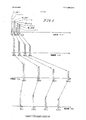
図1は、一連の音4個、および、所定の時点における各音の4個の倍音の特徴的な倍音成分を示す。この仮説的シーケンスは、倍音およびフィルタが基音、倍音、および、相互に対してどのように移動するかを示す。これらの移動する倍音の振幅および周波数両方を時間経過と共に追跡することは、ここに具体化される処理方法における重要な要素(キーエレメント)である。
【0053】
周波数間の間隔または距離(フィルタ間の感覚に対応する)は、基音の周波数が上昇するにつれて膨張し、基音の周波数が低下するにつれて収縮する。図形的に説明すれば、本明細書において、この処理は「アコーデオン効果」として知られている。
【0054】
本発明は、振幅調節のために設定された信号の、非静止の(周波数の変化する)倍音と共に移動するフィルタを用いて、時間経過における倍音の振幅を調節するように設計されている。
【0055】
具体的には、個別の倍音はパラメータ的にフィルタリング、及び/又は、増幅される。これによって、(従来型装置を用いて現在行なわれているように)その中に当該倍音が現れる周波数帯域に基づくことなく、倍音の高さ及び、どの倍音の高さの位数がフィルタリングされるものとして設定されているかに基づき、演奏されている個々の音のスペクトルにおける様々の倍音の相対振幅が増大および減少する。これは、例えば、音楽または複合波形の記録の後でオフラインに実施されてもよいし、または、ほぼリアルタイムに実施されてもよい。これがほぼリアルタイムに実施されるためには、個別に演奏された音の倍音周波数は、周知の周波数検出法または高速基音検出(Fast Find Fundamental)方法を用いて決定され、次に、決定された音に対して倍音別のフィルタリングが実施される。
【0056】
倍音はこの独特の仕方において操作されるので、1つ又は複数の固定された共振帯域に割り当てられた従来型フィルタを用いるとスペクトルの断片にのみ作用するのとは対照的に、精密に選択された個別倍音に関して楽器の全体的音色が影響される。
【0057】
説明を容易にするために、図1−3に示す倍音関係のモデルはfn=f1xnとする。
【0058】
例えば、次の2つの音(図1の音1と音3)の第4倍音は周波数レンジが異なるが、この形式のフィルタは400Hzである第4倍音を、2400Hzの第4倍音をフィルタリングするのと同じ方法でフィルタリングするする。本発明のこの適用は、従来型周波数帯域毎の等化装置に対する補足として、及び/又は、代替物として有用なはずである。出力するために、演奏された音のこれらの個別にフィルタリングされた倍音を混合することについては、図4及び5に関して検討することとする。
【0059】
図2は一時点におけるある信号の倍音成分の一例を示す。基音周波数(f1)は100Hzである。従って、100Hzの倍数において、この信号の倍音は200Hz(f2=f1x2)、300Hz(f3=f1x3)、400Hz(f4=f1x4)、等々である。説明のために、この例には合計10個の倍音を示すが、実際の信号は更に多くの倍音を持つ場合が多い。
【0060】
図3は、本発明によって実施可能な図2に示す幾つかの倍音の調節修正を示す。200Hz(第2倍音)、400Hz(第4倍音)、500Hz(第5)、及び、1000Hz(第10)に位置する倍音のエネルギ成分および振幅は上方調節される。600Hz(第6倍音)、700Hz(第7倍音)、800Hz(第8)、及び、900Hz(第9)における倍音のエネルギ成分および振幅は下方調節される。
【0061】
本発明を用いると、倍音は、種々の方法により、振幅が増大または減少させられる、(ここでは、「振幅調整機能」と称する)。現代的一方法は、対象とするタイムフレーム全体に亙って具体的に計算されたデジタルフィルタを適用することである。これらのフィルタは調節されつつある倍音の周波数の移動に応じてフィルタの振幅および周波数を調節する。更に、別の方法でも、デジタル信号処理を用いて、例えば、シヌソイド(正弦曲線)の位相を対象とする倍音に一致させ、次に、(A)減少させるためには、元の信号に反転波形を加えることにより、所要量を減算し、又は(B)強化するためには、基準化されたバージョンの波形(すなわち、所望の係数が乗じられる波形)を加算する。
【0062】
他の実施形態においては、周波数が隣接する一連のフィルタ又は一連の固定周波数フィルタを使用する。この場合、1つの倍音があるフィルタレンジから次のフィルタレンジに移動する際に、処理工程は「バケツリレー」方式で手渡される。
【0063】
図4は実装実施形態を示す。ピックアップ、マイクロホン、または、事前記憶されたデータからの入力10における信号は倍音信号検出HSD12、および、フィルタのバンク14に供給される。バンク14における各フィルタは倍音検出信号の特定の倍音周波数に関してプログラム可能であり、f1、f2、f3...fNによって表される。コントローラ16は各フィルタの周波数を、当該倍音の高さに関する倍音信号検出器12によって検出された倍音周波数に一致する周波数に合わせる。個別倍音の所要の修正は、ユーザ入力に基づいてコントローラ16によって制御される。フィルタのバンク14の出力はミキサ18において入力10からの入力信号と組合わされ、使用される所定のアルゴリズムに依存する出力20に、組み合わせ出力信号として供給される。以下に、図3に関して検討するように、コントローラ16は、ミキサ18においてイコライザバンク14および入力10からの信号と組合わされるべき合成倍音も同様に供給する。
【0064】
図5は交互バケツリレー方式を実施するように修正されたシステムを示す。イコライザバンク14’はフィルタのバンクを有し、それぞれのフィルタはFa、Fb、Fc、等々によって表される固定周波数隣接帯域幅を有する。コントローラ16は、倍音信号検出器12によって識別される倍音信号を受け取ると、検出された倍音信号の特性と一致するように、14’の固定帯域幅フィルタの特性の信号修正を調節する。ここで、図4のバンク14内フィルタの各々の周波数は所要倍音に調節され、修正特性は所要倍音用に固定される。図5のバンク14’のイコライザは各々周波数が固定され、それらの修正特性は検出された倍音信号に応じて変えられる。
【0065】
アコーデオン周波数および振幅調節可能移動フィルタ法が使用されても、これらの方法の後に行なわれるか、これらの方法と組み合わされる予想周波数のバケツリレー法が使用されても、フィルタリング効果は振幅変化用に選択された倍音を用いて、信号の周波数ばかりでなくその倍音高さ及び振幅に応答して周波数を移動させる。
【0066】
倍音信号検出器12はコントローラ16とは別に図示されているが、両者は共通のDSPまたはマイクロコンピュータのソフトウェアであってもよい。
【0067】
フィルタ14はデジタルであることが好ましい。デジタルフィルタリングの利点は、位相歪みと呼ばれる元の信号と処理された信号の間の望ましくない位相シフトを最小限にできることである。本発明の一方法においては、所要目標に応じて2つのデジタルフィルタリング方法、即ち有限インパルス応答(FIR)方法、または無限インパルス応答(IIR)方法のどちらでも使用可能である。有限インパルス応答方法は振幅調節及び位相補償のために、分離された個別のフィルタを使用する。振幅調節フィルタは、所要応答が入力信号の周波数の関数となるように設計されてもよい。デジタルフィルタは、その振幅応答特性が本質的にデータアレの位相特性に影響して、これを歪めるように設計される。
【0068】
その結果、振幅調節フィルタには直列配置された位相補償フィルタとしての第2フィルタが後続する。位相補償フィルタは単位利得デバイスであり、振幅調節フィルタによって導入された位相歪みに対抗する(逆らう)。
【0069】
フィルタ及び他のサウンドプロセッサは、2つのタイプの入力オーディオ信号、即ちリアルタイムまたは非リアルタイム(固定または静的)のどちらにも適用可能である。リアルタイム信号には、プライベートな設定場所、公共アリーナ、又は、録音スタジオのいずれかにおいて行われる生の演奏が含まれる。一旦、複合波形がデジタル形式で磁気テープ又はその他の媒体に録音されると、当該波形は固定すなわち静的であるとみなされ、さらなる処理が可能である。
【0070】
入力信号にデジタル処理が適用可能となる前に、当該入力信号自体がデジタル情報に変換されなければならない。アレイは信号のデジタル表現を示す数列である。フィルタは、アレイの始めから終わりに向かって前進方向に適用されるか、又は、終わりからはじめに向かって後退方向に適用される。
【0071】
第2のデジタルフィルタリング方法、即ち無限インパルス応答(IIR)において、対象とするデータアレイに亙って両方向にフィルタを適用することにより、ゼロ位相フィルタリングが非リアルタイム(固定、静的)信号を用いて達成される。位相歪みは両方向において等しいので、フィルタが両方向に実行されるときにおける正味効果は、このような歪みが相殺されることである。この方法は静的な(固定され、記録された)データに限定される。本発明の一方法においては、高速デジタル計算デバイス、ならびに、ディジタル化された音楽を定量化する方法が用いられ、高速フーリエ、及び/又は、ウェーブレット解析に対する付加物として数学的アルゴリズムを改良する。デジタルデバイスは既存の音楽を解析し、倍音の音量または振幅を所要レベルに調節する。この方法は、倍音と共に周波数が移動し、所要倍音レベルが図4に示すように変化する非常に急速に変化する複合ピンポイントデジタル等化ウィンドウを用いて達成される。
【0072】
本発明は、ギター、バス、ピアノ、等化およびフィルタリングデバイス、記録に用いられるマスタリングデバイス、電子キーボード、オルガン、楽器音修正器、および、他の波形修正器に適用可能であるが、これらに限られない。
【0073】
(倍音合成)
楽音または他のオーディオ信号の倍音成分のエネルギレベルを調節することが望まれる多くの状況において、倍音成分が断続的であるか、または、事実上存在しないならば、前記の調節を実施することは不可能である。これは、倍音がソース信号のノイズ「フロア」(認識可能な最小エネルギレベル)を下回るようにフェードしたときに発生する。本発明を用いれば、これらの欠落またはフロアを下回る倍音は「スクラッチから」生成可能、即ち、電子的に合成される。更に、ソースに対する整数乗数関係または非整数乗数関係のいずれかを用いて、完全に新しい倍音、非倍音、または、分周音(基音より低い周波数の倍音)をすべて一緒に作ることも同様に望ましい。再び、この創作または生成処理は合成の一タイプである。自然に発生する倍音のように、合成された倍音は一般にそれらの基音の周波数に数学的に関係する。
【0074】
倍音調節の場合のように、本発明によって生成される合成倍音の周波数は非静止であり、合成倍音は他の倍音に対して移動する。合成倍音は任意の個別倍音(f1を含む)に対して合成され、音の周波数が変化すると、その変化が倍音シンセサイザを正しく調節することが予想しつつ、合成倍音の周波数が移動する。
【0075】
図2に示すように、元の信号の倍音成分は1000Hz(100Hz音の第10倍音)までの周波数を含み、第11または第12の倍音は存在しない。図3は、倍音合成によって生成されることによってこれらの欠落倍音が存在する場合を示す。従って、新たな倍音スペクトルには1200Hz(第12倍音)までの倍音が含まれる。
【0076】
楽器は、可聴スペクトルにおける倍音の相対レベルのみならず音に対する倍音の位相(時間経過と共に変化する関係)によっても定義される。従って、倍音合成は、振幅的に相互関係を持ち、かつ位相的に位置合わせされた(即ち、任意にではなく一貫的に基音に対して一致、又は、関連する)倍音の創造も可能にする。フィルタのバンク14及び14’は、同様にデジタルサイン波生成器でもあるデジタルデバイスであることが好ましく、合成倍音は、fn=f1xn以外の関数を用いて生成されることが好ましい。新たな倍音を生成するための好ましい関係はfn=f1xnxSlog 2 (n)である。Sは1より大きい数、例えば1.002である。
【0077】
(倍音調節および合成)
倍音調節と倍音合成の組み合わせは,「欠落している」とみなされる倍音を含めて1つの音に含まれる全ての倍音の振幅をそれらの倍音高さに基づいて動的に制御する能力を具体化する。倍音を制御するこの能力は、種々様々の音または信号の音色をユーザの好みに合わせて操作する大きい融通性をユーザに与える。本方法は、特定の入力信号の倍音レベルに基づいて種々異なる操作が望まれることを認識する。この方法は倍音調節および倍音合成を具体化する。既に存在するスペクトルの断片にのみ作用する場合と対照的に、楽器全体の音色が影響される。
【0078】
倍音がソース信号のノイズ「フロア」を下回るようにフェードアウトする場合のように、倍音成分が断続的であるか、又は、事実上存在しないならば、信号の倍音成分のエネルギレベルを調節することは不可能である。本発明をもちいると、これらの欠落したまたはフロアを下回る倍音は「スクラッチから」生成され、すなわち、電子的に合成されることが可能であり、その後で、元の信号、及び/又は、倍音的に調節された信号に混合し直される。
【0079】
これに関しては、ソース信号の全倍音応答を修正するために、倍音調節と関連して倍音合成も使用可能である。例えば、図6に示すように、エレキギターの第10倍音は、倍音高さがより低い倍音よりはるかに迅速に衰微する。音の初期部分における当該倍音のレベルをブーストするためだけでなく、当該倍音のレベルを当該音が存在する全期間に亙って維持するためにも合成を使用することは興味深い。合成は、選択された区分または通路における全ての音に対して実施される。従って、既存の倍音は、その倍音が或る閾値を越える部分的期間中に調節され、その後、当該音の残りの部分的期間中に(その調節された形において)合成される(図7参照)。
【0080】
幾つかの倍音に関してこれを達成することが望まれることもあり得る。この場合、当該倍音は、所要閾値に振幅を維持するために所要の位相位置合わせを用いて合成される。位相位置合わせは任意の設定を起点とすることもできるし、又は、位相は何等かの方法によりユーザが選択した倍音に位置合わせすることもできる。この方法においては、非常に高速で周波数、及び、振幅が変化し、及び/または、音の倍音エネルギ成分を変えるように非常に高速で移動し、所要の欠落倍音を加えるようにシンセサイザと調和して作用する。これらの倍音および合成された倍音は音量においてデジタルデバイスのソフトウェアに設定された百分率における設定倍音の振幅に比例する。新たな倍音を生成するためには、関数fn=f1xnx(S)log 2 (n)が用いられることが好ましい。
【0081】
存在しない倍音をブーストしようとする試行を回避するために、本発明は、検出アルゴリズムを使用して保証された調節を行うために十分な部分音が存在することを示す。一般に、この種の検出方法は、部分音エネルギ(または振幅)が、任意に定義された或る期間に亙って或る閾値以上である限り、存在するものと見なされるように、部分音のエネルギに基づく。
【0082】
(倍音変換)
倍音変換は、1つのサウンドまたは信号(変換対象のファイル)と他のサウンドまたは信号(第2ファイル)とを比較し、その後、倍音調節および倍音合成を使用して変換対象の信号を調節し、それによって当該信号が音色において第2ファイルに一層近く類似するか、或いは、第2ファイルと全く同じにする。これらの方法は、既に言及した発明の幾つかの態様を組み合わせることにより、オーディオサウンドを組み合わせるという目的、又は、あるサウンドを別のサウンドにより近づけるという目的を達成する。実際、録音された楽器または音声のサウンドを他の楽器または音声のサウンドにほとんど精確に似せるために、これを使用することができる。
【0083】
楽器または音声によって生成された或る音を、時間に対する、その倍音の周波数成分の観点から観察した場合(図6)、各倍音がアタック特性(当該倍音の初期部分が時間においてどのくらい速く立ち上がり、どのようにそのピークに達したか)、サステイン特性(アタック部分の後で、倍音構造がどのように動くか)、および、ディケイ特性(音の終わりの部分において倍音がどのように停止または衰微するか)を持つことが分かる。音自体が終了する以前に、特定の倍音が完全に衰微している場合もある。
【0084】
1つのタイプの楽器の異なる例(例えば、2台のピアノ)は、多くの点において異なる。その一つのバリエーションは、特定の複合時間領域信号の倍音成分ある。例えば、1台のピアノで出したミドル「C」音は、別のピアノで出した同じ音と、非常に異なった倍音成分を持つ。
【0085】
2台のピアノが異なり得る別の点は、時間経過に対する倍音成分である。2台の異なるピアノで演奏された同じ音は、倍音構造が異なるばかりでなく、これらの構造は時間経過と共に異なる仕方で動作する。1つの音の或る倍音は、別のピアノで出した同じ音の倍音構造の時間経過に対するふるまいと比較して、非常に異なる仕方でサステインまたはフェードアウトする。
【0086】
録音された楽器によって生成される各信号の倍音を個々に操作することによって、当該楽器の応答を別の異なる楽器の応答に密接に類似させるか、又は、一致させることが出来る。この技法は倍音変換と呼ばれる。この技法は、各音内の倍音エネルギレベルを動的に変更し、時間経過におけるそれらのエネルギ応答を別の楽器の倍音エネルギレベルに密接に一致させるように調整する。これは、倍音ランキングに関係する周波数帯域比較によって達成される。第1ファイル(倍音的に変換されるべきファイル)の倍音が、第2ファイルのアタック、サステイン、および、ディケイ特性と一致するように、第1ファイルの倍音は目標とするサウンドファイルと比較される。
【0087】
倍音は一対一に対応しないので、調節用規則を設定するために、アルゴリズムによる比較解析が必要とされる。この処理は、一般的な処理に際して、ユーザからの入力によって援助されることも可能である。
【0088】
この種の操作の一例はフルートとピアノに見られる。図8aから8dまでは、特定の時点におけるピアノ及びフルートに関するスペクトル成分のプロットを示す。図8aは、一般的なフルートの初期の音におけるスペクトル成分を示す。図8bは同一音の非常に後期におけるフルートの倍音成分を示す。図8cは一般的なピアノからの図8aと同じ相対的時点における同一音を示す。これらの時点において、大量の高倍音エネルギが存在する。ただし、時間経過の後、各音の相対倍音成分は非常に変化した。図8dは、同一相対時点における、図8bと同じであるがピアノから出た音を示す。ピアノの高倍音成分は、音における、この時点のフルートの倍音成分よりはるかに希薄である。
【0089】
1つのサウンドファイルは他のサウンドソースの広大なアレイに更に密接に類似させることが可能であるので、情報は第2のサウンドファイルから直接入力される必要はない。モデルは様々な手段によって作ることができる。一方法は、他のサウンドをその時間経過におけるふるまいに基づいて全体的に特性化し、特徴的な倍音または部分音成分のふるまいに注目することである。従って、変えようとするサウンドファイルの各倍音の処理を導くための、種々の数学的または他の論理的規則を作成可能である。モデルファイルは、他のサウンドファイルから作成され、完全な理論的モデルであってもよいし、又は、実際には、ユーザによって任意に定義してもよい。
【0090】
ユーザがピアノの音をフルートに類似させようとするものと仮定すれば、この処理は、両楽器の相対的特性の考察を必要とする。ピアノは、音の開始時にその倍音内に大きいエネルギバーストを持ち、その後エネルギ成分は急激に落下する。これに比べて、フルートの初期アタックはそれほど顕著でなく、非倍音性を持つ。本発明を用いると、ピアノの各倍音は、全ての音のこの段階においてフルートの対応する倍音および欠落部分音に近似させるか、又は、必要に応じてこれらを合成するように適宜調節される。
【0091】
ピアノの出す音のサステイン部分においては、その高倍音エネルギ成分は迅速に消滅するのに対し、フルートの出す音においては、高倍音エネルギ成分は当該音の継続期間全体に亙って存在する。従って、この部分の期間中、ピアノの倍音を連続して動的に調節することが必要である。実際、或る点においては、倍音がかなり低レベルまで降下すると、倍音成分を置き換えるために合成が要求される。最終的に、これらの2つの楽器においては、音のディケイもわずかに異なり、フルートに一致させるには再び適切な調節が必要とされる。
【0092】
これは、組み合わせて使用され、音周波数を含めて、対象とする信号または音の種々様々な態様のシフトと共に移動するか、又は、これら態様におけるシフトを予想するデジタルフィルタ、調節パラメータ、閾値、および、サイン波シンセサイザの使用によって達成される。
【0093】
(倍音および他の部分音の強調)
本発明において、倍音および他の部分音の強調は、関連周波数レンジ内の他の信号の振幅に関係するそれらの振幅に基づいて、サイン波、部分音、非倍音性、倍音、または、他の信号を調節する方法を提供する。フィルタ振幅位置ガイド又は判定基準として倍音ランキングを置き換えることは、周波数レンジ内の振幅を用いて倍音調節を変更することである。また、倍音調節の場合と同様に、部分音は周波数ならびに振幅が移動するので、部分音の周波数はガイドを調節するフィルタ周波数である。音楽通路に一般的な多くのオーディオエレメント又は他の複合オーディオ信号の中で、本発明を用いた場合に、弱いものは他のものに対してブースト可能であり、ユーザの選択に従ってそれらの動的レンジを圧縮するか、又は、圧縮することなく、強いものは他のものに対してカット可能である。
【0094】
本発明は(1)比較的静かなサウンドまたは信号を分離するか或いはハイライトし、(2)とりわけ背景雑音、歪み、または、混乱、競合、または、ユーザによって好ましくないとみなされるオーディオ信号を含む、比較的大音量の、または他の選択されたサウンドまたは信号を減少させ、(3)より明瞭な、又は、そうでなければ、より望ましい部分音、音声、楽音、倍音、正弦波、その他のサウンドまたは信号、または、サウンドまたは信号の部分の混合を実施する。
【0095】
従来型電子コンプレッサ及びエキスパンダは、本発明によって考慮対象とされる極めて少数のパラメータのみであって、決して全体でないパラメータに従って作動する。更に、この種の圧縮/拡張デバイスの動作は、本発明のこの種のデバイスとは基本的に異なる。強調を用いる場合には、信号の調節はその振幅のみに基づくことなく、その周波数レンジ内の他の信号の振幅に対するその相対振幅によっても調節可能である。例えば、床の上で足を引きずる音は、聞き取るために調節する必要がある場合も又はない場合もあり得る。それ以外には静かな部屋においては、サウンドの調節を必要としないが、強烈に競合している部分音、サウンド、または、信号の背景音に対して同一振幅の同一サウンドが発生している場合には聞き取るために強調を必要とする。本発明はこの種の決定を行い、それに従って動作することができる。
【0096】
本発明の一方法においては、1つの音楽がディジタル化されて、振幅修正して静かな部分音を強調する。現行技術は、当該音楽を固定周波数レンジ内に圧縮することによってこれを達成するが、それによって信号全体がその動的レンジ全体に基づいて影響される。正味の効果は、より静かな通路を増幅することによってより静かな区分を強調することにある。本発明のこの態様は異なる原理で作用する。コンピュータソフトウェアは、複合波形のスペクトルレンジを調査し、特定の設定閾値レベルを下回る個別部分音のレベルを引き上げる。同様に、特定の閾値を上回る部分音のレベルは振幅において引き下げられる。ソフトウェアは複合波形内の全ての部分音周波数を時間経過に対して調査し、変化に関して設定された閾値内の部分音周波数だけを修正する。この方法において、アナログ及びデジタルのハードウェア及びソフトウェアは音楽をデジタル化し、それを何等かの形式のメモリに記憶する。複合波形は、高速フーリエ変換、ウェーブレット、及び/又は、他の適切な解析方法を用いて高い精度において調査される。関連ソフトウェアは経過時間に対して計算された部分音の振幅、周波数、およびタイムスレショルド(時間限界値)、及び/又は、パラメータを比較し、いずれの部分音周波数が振幅修正に関するスレショルド内に所在するかを決定する。これらのスレショルドは動的であり、かつ、どちらかの側の指定された或る周波数レンジ内における調節用に予定された部分音を囲む競合する部分音に依存する。
【0097】
本発明のこの部分は、洗練された周波数選択的等化またはフィルタリングデバイスとして作用し、この場合における選択可能な周波数の数はほとんど無制限である。デジタル等化ウィンドウが生成されて消去され、それによって、聞き取り難かったサウンド内の部分音の始め、ピーク、および、終わりの振幅を変えることによって、聴取者にとってより明瞭になる。
【0098】
対象とされる振幅を持つ信号が他の信号の振幅に対してシフトするにつれて、本発明の融通性は、(1)連続的に変化するように、又は、(2)固定的であって非連続的に変化するように、のいずれかで調節が実施される。実用的効果は、調節を必要とするオーディオ信号の部分を精確に指摘し、その調節を実施するばかりでなく、これらを必要に応じて必要とされる時に限り実施する能力である。フィルタ変化が毎秒約30サイクルより速ければ、フィルタ変化はそれら自身の音を生成する。従って、低音サウンドがフィルタリングによって除去できない限り、これより速い速度の変化は提案されない。
【0099】
本発明の第1の方法(又は、その組み合わせ)は、特定の時点において特定の部分音(または、その断片)に所要の調節を実施するために何が必要とされるかに従って、周波数および振幅が移動するフィルタを用いる。
【0100】
本発明の第2の方法においては、振幅調節用に設定された部分音が1つのフィルタレンジからその次のフィルタレンジへ移動するときに、「バケツリレー」方式で処理が手渡される。
【0101】
本発明は、周波数、時間経過に対する周波数、時間経過に対する周波数帯域内の競合部分音、振幅、および、時間経過に対する振幅を調査することができる。次に、周波数および振幅を調節可能なフィルタ、数式モデル、または、アルゴリズムを使用して、上述の目標、結果、または、効果を達成するための必要性に応じて、これら部分音、倍音、または、他の信号(またはその部分)の振幅を動的に調節する。両方の方法において、部分音、他の信号、または、その部分の周波数および振幅を評価した後で、本発明は、信号を上方または下方調節するか、または、全然調節しないかを、閾値に基づいて決定する。
【0102】
強調は、振幅閾値、及び、調節曲線に従う。本発明において、所要の結果を達成するために、閾値および調節を実施する3つの方法がある。第1の方法は、複合波形の全エネルギに基づいて振幅閾値を動的に調節する閾値を利用する。エネルギ閾値は一貫性のある周波数依存性を維持する(即ち、閾値曲線の勾配が全てのエネルギ変化に対して一貫している)。第2の方法は、調節されようとしている部分音の周りの周波数帯域内の補間された閾値曲線を実現する。閾値は動的であり、この部分音の周りの周波数領域に限定される。また、調節も同一周波数帯域において動的であり、振幅が変化する領域変化内における周りの部分音と同様に変化する。部分音は周波数が移動するので、閾値および調節周波数帯域も周波数において動的であり、調節されようとしている部分音が移動すると、これと共に移動する。第3の方法は固定した閾値レベルを利用する。振幅が閾値を上回る部分音は下方へ調節される。振幅が閾値を下回るがノイズフロアを上回る部分音は振幅において上方調節される。これら3つの方法について以下に検討することとする。
【0103】
3つの方法全てにおいて、調節レベルは「基準化(スケーリング)関数」に依存する。倍音または部分音が閾値を超えるか、または、それを下回るように降下すると、閾値を超えた量またはそれを下回った量が調節の大きさを決定する。例えば、上側閾値をかろうじて超過する部分音は極少量だけ下方調節されるが、閾値を更に超過すると、更に大量の調節が発生する。調節量の遷移は連続関数である。最も単純なこの種の関数は線形関数であるが、任意の基準化関数が適用される。いかなる数学関数を用いる場合でも、閾値を超えるまたはそれを下回るように降下する部分音の調節レンジは基準化されるか或いはオフセットされる。基準化関数の効果が基準化されると、閾値が変化したかどうかには関係なしに、部分音が閾値を超過すると同量の調節が発生する。例えば、既に示した第1の方法において、波形内に更に多くのエネルギが存在するときには閾値が変化する。基準化関数は、依然として、調節されるべき部分音の0%から25%までの間で変動するが、波形内に更に多くのエネルギが存在する場合には比較的小さい範囲で変動する。これの代替操作は、基準化関数を幾らかのパーセンテージだけオフセットすることである。従って、信号内に更に多くのエネルギが存在する場合には、レンジは同じでないはずであり、例えば、この場合、0%から10%のみにまで変化する。しかし、調節量の変化は、閾値を超過した部分音のエネルギ量に対して一貫したものである。
【0104】
第1の閾値および調節方法に従い、振幅の最小および最大限度を画定することにより、信号の部分音成分の一部分に作用することが望ましい。この種の処理においては、2つの閾値の境界、即ち上限または天井と、下限またはフロアとの間に信号が保持されることが理想的である。部分音の振幅は、設定された期間よりも長期に亙って、上側閾値を超え、または、下側閾値を下回るように降下することは許容されない。これらの閾値は、図9Aに示すように、周波数に依存する。ノイズフロアは、実際に単なる低レベルノイズに過ぎない部分音の調節を防止するように確立されなければならない。ノイズフロアは強調のために全体的な下限として作用し、手動により、又は、解析手順を介して確立される。各入力される部分音は2つの閾値曲線と比較されてから、上方(エネルギがブーストされる)または下方(エネルギが低減される)調節されるか、或いは、全然調節されない。ブースト又はカットは部分音周波数レンジにおける全信号振幅に関連するので、閾値曲線は同様に所与の時点における全信号エネルギに依存して変化する。調節量は、部分音のレベルに従って変化する。上述したように、調節は基準化関数に基づいて発生する。従って、調節されるべき部分音が閾値を超えるか、または、閾値を下回るように降下するエネルギ量に依存して調節が変化する。
【0105】
第2閾値および調節方法において、部分音は、当該部分音の継続時間において、調節されようとしている当該部分音の周りの周波数帯域における「競合する」部分音と比較される。この周波数帯域は幾つかの特徴を持つ。これらを図9Dに示す。1)帯域幅は所要の結果に応じて修正され得る。2)閾値及び調節領域の形状は連続的な曲線であり、曲線全体の「線形」部分に適合するように滑らかになる。曲線の線形部分はこの部分音に関する比較および調節領域の外側周波数を表す。ただし、曲線の線形部分の全「オフセット」は波形内における全エネルギに依存する。従って、閾値のオフセットにおける全シフトが観察されるが、調節はそれ自体の周波数領域における部分音に依存するので、特定の部分音の調節は変化しない。比較される周波数帯域における上側閾値は競合する部分音と共に増加する。閾値線を上回る部分音の調節に用いられる基準化関数は同様にシフト又は再基準化(リスケール)する。比較周波数帯域における下側閾値は競合部分音と共に下降する。再び、部分音の調節に用いられる基準化関数は同様にシフト又は再基準化する。3)部分音が閾値を上回るか、又は、閾値を下回るように降下すると、調節は振幅が閾値をどれだけ上回る、または、閾値をどれだけ下回るかに依存する。調節量は、後続部分音の周りの競合部分音内エネルギ分同様にオフセットされる連続的なパラメータである。例えば、部分音が上側閾値をかろうじて上回る場合には、その振幅は、例えば、僅かに5%だけ下方調節される。その振幅が比較的大量に閾値を上回る場合には、部分音が25%だけ調節される更に極端な場合が観察される。ただし、全信号エネルギが異る場合には、閾値オフセットにおける全シフトに対して幾らかのパーセンテージだけこの調節量はオフセットされる。4)実際に低レベルノイズであるに過ぎない部分音の調節を防止するようにノイズフロアが確立されなければならない。ノイズフロアは強調条件に関する全体的な下側限界として作用し、手動または解析手順を介して確立される。
【0106】
第3閾値および調節方法においては、全て同じ調節方法が用いられるが、単一固定閾値に関して比較が行われる。図9cはこの種の閾値の一例を示す。部分音が閾値を上回る、又は、それを下回るように降下した場合には、その調節は、振幅が閾値を上回るまたはそれを下回るように降下する量に依存する。調節量は、部分音内エネルギ分同様にオフセット又は再基準化される連続的なパラメータである。ここでも、上述の方法において述べたように、実際には単に低レベルノイズに過ぎない部分音の調節を防止するようにノイズフロアが確立されなければならない。
【0107】
ヒトの耳自体が平坦ではないので、全ての閾値および調節方法において、閾値(単一閾値または別々の上側および下側閾値)が平坦であるとは限らない。耳は、可聴レンジ全体に亙る均一または線形状態の振幅を認識しない。我々の聴覚応答は周波数依存である(幾らかの周波数では他の周波数よりも多量のエネルギを持つように知覚される)ので、本発明におけるエネルギ調節も周波数依存である。
【0108】
最大と最小振幅調節量間の振幅調節量を補間することにより、更に連続的かつ一貫性のある調節が達成可能である。例えば、その振幅が最大レベルに近い(クリッピングに近い)部分音は、その振幅が下側調節閾値をかろうじて上回る部分音の場合よりも下方調節されるエネルギ量が多いはずである。時間的閾値(タイムスレショルド)は、設定された周波数レンジにおいて競合する部分音が限界を持つように設定される。閾値曲線および調節曲線は、ユーザ希望定義とヒトの耳に基づいた経験的な知覚曲線との組み合わせを表す。
【0109】
図9Aは標本閾値(サンプルスレショルド)曲線を示し、図9Bは閾値及び調節方法1に関連するサンプル調節曲線を表す。閾値(スレショルド)は、全信号エネルギに依存する(例えば、下側全エネルギは閾値を低下させる)。入力される部分音の振幅が上側エネルギ閾値曲線または図9Aの上昇限度(天井)を上回る場合には、部分音は、図9Bの当該周波数に関連する調節曲線によって定義された量だけ部分音のエネルギがカットされる(下方調節される)。同様に、部分音の振幅が下側エネルギ閾値曲線すなわちフロア(床)を下回るように降下すると、そのエネルギは、当該周波数に対して関連する調節関数によって定義される量だけ再びブーストされる(上方調節される)。振幅の増加量、及び/又は、減少量は事前決定された量であってもよい。
【0110】
図9Bの調節関数は所与の周波数において実施される最大調節量を画定する。部分音の振幅への歪みの導入を防止する目的で、最大調節まで滑らかな遷移が実施されるように、調節量は時間経過と共に先細にされる。遷移は任意の関数によって定義され、線形パターンと同程度に単純なものであってもよい。漸進的なテーパ(先細り)なしでは、波形調節は速過ぎるか、または、不連続性を生じ、それによって、調節された信号に不必要、かつ/または、好ましくない歪みを生じる。同様に、部分音を上方調節する場合にもテーパリング(先細にすること)が適用される。
【0111】
図9Cは、第2の閾値および調節方法に関係する一例を示す。
【0112】
信号継続時間全体に亙って、当該信号の倍音/部分音の振幅は、かなり一定であることも変動することもあり、場合によっては、かなり変動する。これらの態様は周波数及び時間に依存し、或る特定の倍音の振幅およびディケイ特性は、競合する部分音に関して或る特定の形でふるまう。
【0113】
倍音(個別倍音または倍音のグループのどちらか)の最大振幅および最小振幅を制御するための閾値に関する前述の検討とは別に、ユーザによって設定される時間を基調とする閾値(スレショルド)も存在する。本発明が部分音を調節していくには、これらの閾値が適合しなければならない。
【0114】
本発明が作動開始するためには、振幅閾値がユーザによって指定された期間において適合するように、時間を基調とする閾値は、指定された調節に関する開始時間、継続時間、および、終了時間を設定しなければならない。例えば、振幅閾値が超過されても、その状態がユーザによって指定された期間に亙って維持されなければ、振幅調節は処理されない。例えば、次に示す条件のいずれかに適合する最小閾値を下回るように降下する信号は調節されない、即ち、(1)当該閾値に一旦適合したが、その後で、それを下回るように降下した場合、または(2)最初から一度も当該閾値に適合しない場合。ソフトウェアが、信号調節におけるこの種の差異を認識し、しかもユーザによって調節可能であれば有用である。
【0115】
(補間)
一般的な意味において、補間とは、所与量および既知変数の間の関係に基づいて2つの所与量間の未知量を推定または計算する方法である。本発明において、補間は倍音調節、倍音の調節と合成、部分音変換、及び、倍音変換に適用される。これは、楽器またはヒトの音声いずれかによって出された音の或る特定点における倍音構造をユーザが調節する方法を意味する。ユーザによって調節されたこれらの点の1つから他の点まで音楽レンジ全体に亙る倍音構造のシフト(移動)は、ユーザによって規定された幾つかの曲線または音調曲線または補間関数に従い、本発明の影響を受ける。このように、演奏された音の倍音成分の修正は連続的な方法で制御される。
【0116】
音声または楽器のサウンドは音域(レジスタ)の関数として変化可能である。異なる音域においてサウンドを変えたいというように願望が変化するため、歌手またはミュージシャンは、別の音域における音を出している状態において、ある1つの音域の特徴または音色を維持することを希望することがある。本発明において、補間は、彼らの願望を叶えるばかりでなく、ユーザによって調節された一方の点から別の点まで音楽スペクトル全体に亙って制御可能な仕方で、音の倍音構造を自動的に調節することも可能にする。
【0117】
ユーザは、高音域の音における第3倍音を強調したいが、中間音域における第10倍音は強調したくないものと仮定することとする。一旦、ユーザがこれらのパラメータを希望通りに設定すれば、本発明は、ユーザによって制御可能な変換特性を用いて、これらの点間における音の倍音構造のシフト(移動)を自動的に実施する。
【0118】
簡単に表現すれば、ユーザが或る特定点における倍音を設定すれば、補間作用はこれら「設定点」間の全てを自動的に調節する。更に具体的には、次に示す2項目が達成される。
* 第1に、ユーザは、音声または楽器レンジ内の異なる点における当該音声または楽器の音(又は、選択されたレンジ内における音のグループ)の倍音構造を調節することができる。その際、ユーザは、当該サウンド内において知覚された不足音を訂正したり、または、特別な効果を生成するようにサウンドを調節したり、または、望ましいと思われる倍音を強調したり、または望ましくないと思われる倍音を減少させるか又は削除したり、または、場合によりあらゆることを実施したりできる。
* 第2に、ユーザが、選択されたこれらの音または音域のサウンドの調節を一旦完了すると、本発明は、設定点間の音楽スペクトル全体に亙って、全ての音および知覚された全ての倍音の倍音構造をユーザによって事前に選択された公式に従ってシフトまたは変換する。
【0119】
補間関数(すなわち、一方の設定点の倍音構造からもう一方までシフトする特性または曲線)は線形であっても、対数的であっても、または、ユーザによって選択された他の音調曲線であってもよい。
【0120】
周波数目盛りは種々様々な音、倍音、部分音、または、他の信号の位置を図に表すことができる。例えば、1目盛りは1オクターブ離れた位置の周波数を図に表してもよい。本発明がユーザ設定点の間の全ての倍音構造を調節する仕方は当該ユーザによって選択可能である。
【0121】
(自然倍音の模倣)
倍音周波数の良好なモデルは、広い共振帯域内において近似自然「シャープ化」に設定可能であるので、fn=nxf1xSlog 2 nである。例えば、f1=185Hzの第10倍音は、10x185を用いる1850Hzの代わりに1862.3Hzである。更に重要なことは、その式が協和倍音、例えば、倍音1は倍音2と、倍音2は倍音4と、倍音3は倍音4と、倍音4は倍音5と、倍音4は倍音8と、倍音6は倍音8と、倍音8は倍音10と、倍音9は12と、等々のように協和する。これらの倍音が、倍音生成に用いられると、自然倍音の場合よりも更に強められて鳴る(ring)。これは、倍音調節および合成、および、自然倍音にも用いられる。この関数またはモデルは、より高い倍音を「シャープ化」する楽器によって生成され、近く一致する倍音を見付ける良好な方法である。このようにして、ストレッチ関数は自然倍音模倣INHに使用できる。
【0122】
関数fn=f1xnx(S)log 2 nはnが増大するにつれて次第にシャープ化する倍音をモデル化するために用いられる。Sはシャープ化定数であり、一般に1と1.003の間に設定され、nは正の整数1、2、3,...,Tであり、ここで、Tは一般に17に等しい。この関数を用いると、Sの値はシャープ化する範囲を決定する。それがモデル化する倍音は、fn=nxf1である場合に倍音が協和すると同じ方法で協和する。即ち、fn及びfmが1つの音のn番およびm番倍音であるならば、fn/fm=f2n/f2m=f3n/f3m=...=fkn/fkmである。
【0123】
例えば、高速基音検出方法、又は、フィルタバンクを介した明白な周波数位置決め技法、又は、自動相関技法などの基音および倍音の周波数を決定するために利用可能な多数の方法がある。特定の演算に必要とされる精度および速度の程度はユーザによって定義され、適切な周波数発見アルゴリズムを選択する助けとなる。
【0124】
(特殊効果のための倍音分離)
本発明およびその方法の更なる拡張はオーディオの独特な操作、及び、オーディオ処理の他の分野への本発明の応用を可能にする。対象とされる倍音はユーザによって選択され、次に、以前に言及した可変デジタルフィルタの使用によって元のデータから分離される。信号を分離するために使われるフィルタリング方法は任意の方法でよいが、特に適用可能な方法は、係数が入力データに基づいて再計算可能なデジタルフィルタである。
【0125】
次に、分離された倍音は他の信号処理ユニット(例えば、残響、コーラス、フランジ、等々の楽器用エフェクト)に供給され、最終的に、ユーザによって選択されるブレンド又は比率で元の信号へ混合して戻される。
【0126】
(具体化)
具体化される1つの変形例には、例えば、デスクトップパソコン24等のホストコンピュータシステムであって、追加機能を実施するために、システム内にインストールされる幾つかの増設カードを有するホストコンピュータシステムへ接続されたオーディオ信号22のソース(供給源)が含まれる。ソース32は生の演奏であっても、記憶されたファイルから得られてもよい。これらのカードには、アナログ−デジタル変換カード26及びデジタル−アナログ変換カード28、並びに、高速で計算およびフィルタリング処理を行なうために用いられる追加デジタル信号処理カードが含まれる。ホストコンピュータシステムは主にユーザインタフェース処理を制御する。ただし、汎用パソコンのプロセッサは、デジタル信号プロセッサカードをインストールすることなしに、全ての計算を単独で実行する。
【0127】
入力されるオーディオ信号は、電気サウンド信号をデジタル表現に変換するアナログ−デジタル変換ユニット26へ供給される。一般的な用途において、アナログ−デジタル変換は20から24ビットのコンバータを用いて実施され、48kHz−96kHz[および、おそらくは更に高い]サンプルレートで作動する。パソコンのサンプルレートは、一般に、16ビットのコンバータでサポートされる8kHz−44.1kHzである。これらは、幾らかの用途には十分である。ただし、例えば、20ビット、24ビット、32ビットなどの大きいワードサイズである方が更に良好な結果が得られる。また、サンプルレートが高ければ、変換された信号の品質が改良される。デジタル表現は、数の長いストリームであり、ハードディスク30に記憶される。ハードディスクは、例えば高性能取外し可能ディスク型媒体などのような独立型ディスクドライブであってもよいし、コンピュータ用の他のデータ及びプログラムが存在する同一ディスクであってもよい。性能および融通性に観点から、ディスクは取外し可能型である。
【0128】
一旦、ディジタル化されたオーディオデータがディスク30に記憶されると、信号の所要操作を実施するために、プログラムが選択される。プログラムは、実際には、所要の目標を達成するための一連のプログラムで構成される。この処理アルゴリズムは、処理アルゴリズムによって制御されたランダムアクセスメモリ(RAM)に記憶されているコンピュータデータを、可変サイズユニット内のディスク32から読み取る。処理が完成すると、処理されたデータはコンピュータディスク30で再び記憶される。
【0129】
本発明において、ディスクに対する読み取り及び書き込み処理は、読み取りと書き込みが混合され得るように、又、データセクションが多数回読み書き可能であるように双方向的、及び/又は、再帰的であってもよい。ディスクによるデジタルオーディオ信号のアクセス及び記憶は、システムを遅延させるので、オーディオ信号のリアルタイム処理においては最小限化される必要があることが多い。RAMのみを利用するか、または、キャッシュメモリを利用することによって、システムの性能は、幾らかの処理がリアルタイム又はほぼリアルタイム方式で実施され得る点まで向上可能である。リアルタイムとは、ユーザが感知可能な待ち時間が殆ど無いか、又は、一切無しに結果が得られるような速さで処理が発生することを意味する。処理の型およびユーザの好みに応じて、処理されたデータは上書きされるか、または、元のデータと混合される。新たなファイルへ一緒に書き込まれても、書き込まれなくてもよい。
【0130】
処理が完了すると、再度聴くため、又は、更なる外部処理34のために、データがコンピュータディスク又はメモリ30から読み取られる。ディジタル化されたデータはディスク30から読み取られ、デジタル−アナログ変換ユニット28へ書き込まれる。このユニットは、コンピュータ34外で使用するためにディジタル化されたデータをアナログ信号に変換し戻す。あるいは、ディジタル化されたデータは、(例えば、AES/EBU、または、SPDIFデジタルオーディオインタフェースフォーマット又は代替形式など)様々な手段を介して、直接デジタル形式で、外部デバイスへ書き出してもよい。外部デバイスには、記録システム、マスタリングデバイス、オーディオ処理ユニット、放送ユニット、コンピュータ、等々が含まれる。
【0131】
処理は、ユーザが感知可能な待ち時間が殆ど無いか、又は、一切無しに結果が得られるような速さで発生する。処理の型およびユーザの好みに応じて、処理されたデータは上書きされるか、または、元のデータと混合される。新たなファイルへ一緒に書き込まれても、書き込まれなくてもよい。
【0132】
処理が完了すると、再度聴くため、又は、更なる外部処理34のために、データがコンピュータディスク又はメモリ30から読み取られる。ディジタル化されたデータはディスク30から読み取られ、デジタル−アナログへ変換ユニット28へ書き込まれる。このユニットは、コンピュータ34外で使用するためにディジタル化されたデータをアナログ信号に変換し戻す。あるいは、ディジタル化されたデータは、(例えば、AES/EBU、または、SPDIFデジタルオーディオインタフェースフォーマット又は代替形式など)様々な手段を介して、直接デジタル形式で、外部デバイスへ書き出してもよい。外部デバイスには、記録システム、マスタリングデバイス、オーディオ処理ユニット、放送ユニット、コンピュータ、等々が含まれる。
【0133】
(高速基音検出)
本明細書に開示された具体例は、例えば高速基音検出方法などのような技術も利用する。この高速検出方法技術は、リアルタイムに実施される必要な後続のアルゴリズムが、顕著な待ち時間無しに(又は、大きくない待ち時間と共に)実施可能であるような非常に迅速な方法において、更に高い倍音の倍音関係からオーディオ信号の基音周波数を推定するためのアルゴリズムを使用する。高速検出アルゴリズムは、倍音処理が迅速かつ能率的に実施されるように、検出された高い倍音及び振動数のランキング数と、未検出の高い倍音のランキング数を推定することができる。また、このような処理は、基本振動数を知ることなく又は推測することなく行う事ができる。
【0134】
本方法は当該信号内の少なくとも2つの候補周波数を選択することを含む。次に、候補振動数のセットの構成要素が、ある倍音関係を持つ適当な倍音周波数のグループであるかどうかが決定される。各倍音振動数のランキング数が決定される。最終的に、音周波数が、適当な周波数から推定される。
【0135】
この方法の1つのアルゴリズムにおいて、検出された部分音間の関係が、全てのメンバーが適当な倍音周波数である場合に有効な類似の関係と比較される。比較される関係には、周波数比、周波数の差、これらの差の比率、および、倍音周波数が整変数の関数によってモデル化されるという事実から得られる一意的関係が含まれる。また、候補者周波数はまた、当該信号のソース(音源)によって生成可能な音周波数、及び/又は、より高位の倍音周波数の下側および上側限界を用いて選別される。
【0136】
このアルゴリズムは、より高い倍音間の関係、選択を限定する条件、より高い倍音が基音に対して有する関係、および、可能性のある基音周波数のレンジを使用する。fnがn番目の倍音の振動数、f1が基本振動数、nが正の整数とし、fn=f1xnxG(n)が倍音振動数をモデル化すると、同じ根元に由来する正当な倍音振動数である場合に優勢であるべき部分音周波数の間の関係の例は以下のようになる。
a)候補振動数fH,fM,fLの比率は、倍音のモデルにおけるそれらのランキング数RH、RM、RLを置き換えることによって得られる比率にほぼ等しくなくてはならない。すなわち、fH÷fM≒G(RH)÷G(RM)}、および、fM÷fL≒G(RM)÷G(RL)。
b)候補振動数間の差の比率はモデル化された振動数の差の比率と合致しなければならない。即ち、(RH−RM)÷(RM−RL)≒{G(RH)−G(RM)}÷{G(RM)}÷G(RL)]。
c)候補周波数部分音fH、fM、fLは、ソース又は楽器によって生成可能な周波数レンジ内に所在しなければならない。
d)倍音の高さの位数RH、RM、RLは、ソース又は楽器によって生成可能な基音周波数レンジ内、即ち、FLを下回るかFHを上回る基音周波数を意味してはならない。
e)可能性のある3個の倍音の高さの位数を得るように整数可変比率を一致させる場合に、例えば、整数比率RH/RMにおける整数RMは、整数比率RM/RLにおける整数RMと同じでなければならない。この関係は、倍音の高さの位数の組{RH、RM}および{RM、RL}を可能性のある3個の位数(RH、RM、RL)に結合するために用いられる。
【0137】
他のアルゴリズムは、倍音関係の中の測定された部分音振動数のセットと、それらに由来する個々の振動数及び基本振動数のランキング数を即座に特定するための擬似されたスライド規則を使う。この方法は、関数fn=f1×G(n)のG(n)に対応する倍音乗数値がマークされる目盛りを具体化する。マークされた乗数の各々は、対応するnの値に付けられる。計測された部分音の振動数は、同様の目盛りでマークされ、これらの目盛りはそれらの相対位置変化と比較され、乗数のセットとマッチする部分音の振動数のセットを分離する。ランキング数は、乗数目盛りから直接読むことが出来る。これらは、nの対応する値である。
【0138】
ランキング数と振動数は、その後、どのセットが正当な倍音であるかを求めるために使用され、対応する基本振動数も乗数目盛りから直接読み出すことができる。
【0139】
上述したアルゴリズムと他の関係するアルゴリズムの総合的な説明のために、PCT国際出願PCT/US99/25294、高速基音発見方法、WO 00/26896、2000年5月11日出願、を参照する。
【0140】
(他の具体化)
本発明の原理に従って複合波形を変更するための各種システムおよび方法の潜在的相互関係を図11に示す。入力信号は複合波形として音響ファイルへ供給される。次に、この情報は高速発見基音方法または回路へ供給され得る。これは、複合波形の基音振動数を迅速に決定するため、または、更なる倍音調節、及び/又は、合成のために情報を提供するための先駆者として、使用可能である。分析がほぼリアルタイムで実施されなければならない場合には、これは、とりわけ真である。
【0141】
倍音調節、及び/又は、合成は、移動する目標、または、振幅および振動数に関して調節可能な変化するデバイスに基づく。オフライン態様において、倍音調節/合成は、その入力を音響ファイルから直接受け取るはずである。出力は倍音調節/合成から直接可能である。
【0142】
その代りに、特殊効果用倍音の分離、補間、または、自然倍音模倣のいずれかと、ここで示した方法によって組合わされた倍音調節及び合成信号は、出力信号として供給可能である。
【0143】
移動目標に基づく倍音及び部分音強調は、複合波形の音響ファイルの入力から直接オフラインの入力信号を受け取るか、又は、出力として倍音調節、及び/又は、合成を形成する。それ(倍音強調)は、システムから出力信号を供給するか、または、倍音変換へ入力として供給する。倍音変換は、移動目標に基づき、かつ、目標ファイル、補間、および、自然倍音模倣を含む。
【0144】
本発明は、当該記述が主題の実例を示すような表現によって記述された。本記述は限定的意味を持つことなく本発明について記述することを意図するものである。上述の方法には、多くの改変、組合わせ、及び、変更が可能である。従って、本発明は、ここに明確に記述した以外の方法において実行可能であることを理解されたい。
【図面の簡単な説明】
【図1】 振動数対振幅目盛りにおける4つの楽音および4つのグラフを示す図である。これらは相互に関係し合い、倍音のアコーディオン効果を生じる。
【図2】 振動数対振幅目盛り上の特定時点における楽音の倍音内容のグラフである。
【図3】 本発明の原理が組み込まれた図2の個別振動数および合成振動数の調節を示す図である。
【図4】 本発明に従って振幅および振動数追従フィルタ方法を用いた図3に示す方法を実施するシステムの第1実施形態を示す概略図である。
【図5】 本発明に従うバケツリレー方法を用いた図3の方法を実施するシステムの構成図ある。
【図6】 振動数(X軸)、時間(Y軸)、大きさ(Z軸)の関数としての440ヘルツピアノ鍵盤の単一指弾から発生する複合波形のスペクトルプロファイルグラフである。
【図7】 倍音および他の部分音強調、及び/又は、倍音変換の原理に従って変更された信号のグラフである。
【図8】 フルートとピアノの同一楽音の早期および後期両時限における倍音変換に関するスペクトル内容を示す図である。
【図9a】 本発明に従った強調方法を実施するポテンシャルしきい値曲線を示すグラフである。
【図9b】 図9Aと共に用いられる調節方法のポテンシャル低レベルを示す図である。
【図9c】 倍音および他の部分音強調のためのポテンシャル固定しきい値方法を示すグラフである。
【図9d】 倍音および他の部分音強調方法に関する振動数帯域動的しきい値例曲線を示すグラフである。
【図10】 本発明の操作を実施するシステムの構成図である。
【図11】 本発明の原理が組込まれたソフトウェア又は方法段階の構成図である。
【符号の説明】
10 入力
12 信号ディテクタHSD
14 フィルタバンク
16 コントローラ
18 ミキサ
20 出力
24 コンピュータ
22 オーディオ信号
26 A/D変換
30 コンピュータハードディスク
32 信号処理およびアルゴリズム
28 D/A変換
34 外部処理または記録デバイス[0001]
(Cross reference)
This application is related to and claims the provisional patent application 60 / 106,150 filed Oct. 29, 1998, which is incorporated herein by reference.
[0002]
(Glossary, background, and summary of invention)
The present invention relates generally to audio signal processing and waveform processing, and to correcting the harmonic content of periodic audio signals, and more particularly to altering sound or sound perception. The present invention relates to a method for dynamically changing a harmonic component of a signal.
[0003]
Many terms used in this patent are collected and defined in this section.
[0004]
Of the many types of sounds that continuously impact the human ear, one sound has an amplitude, tone (pitch), and pitch (pitch) characteristics that are characteristic of that sound. They are distinguished by features that are long enough to be understood and stable. This type of sound is called a tone.
[0005]
A characteristic that makes it possible to distinguish a specific sound from sounds having the same frequency and loudness (volume), that is, amplitude, is the quality of the musical sound (tone), that is, the timbre (tamba). Using less technical terms, the factors that give a musical instrument an individuality or character that can be recognized are expressed as being largely harmonic components of that sound over a period of time.
[0006]
Some instruments produce stable tones (tones) that can remain characteristically unchanged for at least a few seconds, which corresponds to a period sufficient for several hundred cycles to occur. This type of sound is referred to as periodic.
[0007]
Most sound sources, including musical instruments, produce a composite waveform that is a mixture of sine waves with different amplitudes and frequencies. Each sine wave involved in a complex sound is called a partial tone or simply a partial of that sound. A partial sound or partial frequency is defined as a limited energy frequency band, and a harmonic or harmonic frequency is a mechanical object such as a string or an air column divided by an integer number of nodes. It is defined as a partial sound generated according to a phenomenon based on an integer relation. The sound quality or timbre of a particular complex tone is determined by the volume, frequency, and amplitude of the divided partials, particularly their mutual amplitude ratio and mutual relative frequency (ie, these elements are combined or mixed). To be determined). Musical sounds played with musical instruments have a tone similar to other musical sounds played with the same musical instrument, so frequency alone is not a determining factor. In the embodied system dealing with sound, partials actually represent energy in a small frequency band and are dominated by the sampling rate and uncertain issues associated with the sampling system.
[0008]
Audio signals, particularly those related to musical instruments or human speech, have a specific harmonic component that defines how the signal produces sound. Each signal is composed of a fundamental frequency and higher harmonic frequencies. The graphic pattern for each of these combined cycles is a waveform. The detailed waveform of the composite wave depends in part on the relative amplitude of the multiple harmonics. Changing the amplitude relationship, frequency relationship, or phase relationship between multiple harmonics changes the way the ears hear about the musical nature of the sound.
[0009]
Fundamental frequency (first harmonic or f1And higher harmonics (f)2To fnAre generally mathematically related. In a sound generated by a general musical instrument, a high harmonic is almost an integer multiple of the fundamental frequency, but is not limited thereto. That is, the second overtone is twice the frequency of the fundamental, the third overtone is three times the frequency of the fundamental, and so on. These multiples are often referred to as height (ranking number or rank). In general, the term “overtone” as used in this patent refers to all overtones including the fundamental.
[0010]
Each harmonic has a relationship with respect to the fundamental frequency in terms of amplitude, frequency, and phase, and these relationships can be manipulated to change the sound that is heard. A periodic complex tone is divided into its components (fundamental tone and higher harmonics). The graphical representation of this analysis is called a spectrum. Therefore, a tone color peculiar to a certain sound is graphically represented in the spectrum profile.
[0011]
Common instruments often produce sounds that contain primarily harmonics or multiple harmonics that are close to multiples, but various other instruments and sound sources (sources) are further between the fundamental and higher harmonics. Generate sounds with complex relationships. Many musical instruments produce partials that are not integer multiples. These soundsUnharmonic sound (non harmonic)Called.
[0012]
Modern equal temperament (or scale in Western music) is a method of adjusting the scale to be composed of 12 equally spaced semitones per octave. The frequency of an arbitrary semitone is the 12th root of 2 times the frequency of the immediately preceding semitone, that is, 1.05944631 times. This produces a scale in which the frequencies of all octave intervals are in the ratio 1: 2. These octaves are limited to harmonic intervals only, and all other intervals are incongruent.
[0013]
Due to the inherent compromise (intermediateness) of the scale, for example, a piano can be played with all keys. However, overtones in most mechanical instruments are not exact multiples, but are "early perceptible", so in some instruments their tunes are "stretched", ie a simple mathematical formula Since the tune deviates from the pitch (tone) regulated by the sound, an instrument such as a piano that is tuned accurately to the equal temperament sounds perfectly flat in the high-pitched range to the human ear. These biases are either slightly sharper or slightly flatter for sounds defined by simple mathematical formulas. In stretch tuning, the mathematical relationship between sound and harmonics still exists, but these relationships are more complex. The relationship between harmonic frequencies generated by many classes of transmitter / oscillators including musical instruments is modeled by the function
fn= F1xG (n)
Where fnIs the frequency of the nth harmonic, and n is a positive integer representing the height of the harmonic. Here is an example of this type of function:
a) fn= F1xn
b) fn= F1xnx [1+ (n2-1) β]1/2
Here, β is a constant that depends on the musical instrument or the string of the multi-string device and may depend on the frequency range of the sound being played.
[0014]
The perceived pitch (pitch) of audio or music is generally (but not always) the fundamental or lowest frequency in a periodic signal. As previously mentioned, musical tones include different amplitude-related, frequency-related, and phase-related harmonics. Overlapping these harmonics creates a composite time domain signal. The amount and amplitude of harmonics contained in the signal most strongly represents its timbre or musical personality.
[0015]
Other aspects of the instrument's perceived musical tone or characteristics may be a particular segment of the audible spectrum that is emphasized or enhanced by the design, size, material, construction details, features, and method of operation of the instrument. Includes a resonant band that is part. These resonance bands are perceived as louder than other sections of the audible spectrum.
[0016]
This type of resonance band has a fixed frequency and is constant when another different sound is played by the instrument. These resonance bands do not move (shift) with respect to another different sound played by the instrument. These are determined by the physical nature of the instrument, not the specific sound played at any given time.
[0017]
The main difference between the harmonic component and the resonance band is that the relationship to the fundamental frequency is different. Overtones shift with changes in the fundamental frequency (ie, the overtones are directly linked to the fundamental to be played and move in frequency) and are therefore always relative to the fundamental. As the fundamental shifts to another new fundamental, the harmonics of those fundamentals change with them.
[0018]
In contrast, the resonance band of the instrument is fixed in frequency and does not move linearly as a function of the moving fundamental.
[0019]
Apart from the overtone structure of the sound itself and the resonance band of the instrument itself, other factors related to the perceived sound or musical characteristics of the instrument require how the overtone component changes over the duration of the tone. And The duration of a musical tone, or “life span”, is its attack (a characteristic way in which the sound is first struck or played), sustain (the duration of the sound played over a period of time), and Decay (a characteristic way the sound ends, eg sudden cut-off vs gradual fade) is characterized in this order.
[0020]
The harmonic component of the sound over three stages, ie, attack, sustain, and decay, provides important perceptual hints to the human ear with respect to the main sound quality of the sound. Each overtone in the composite time domain signal including the fundamental has its own characteristic attack and decay characteristics that help define the timbre in the time of the sound.
[0021]
The relative amplitude level of the harmonic overtone changes during the life span of the sound with respect to the amplitude of the fundamental tone (which is sometimes emphasized or attenuated), so that the tone of a particular sound will vary over the duration of the sound. Change. In instruments that are played or struck (like pianos and guitars), the higher harmonics decay faster than the lower harmonics. In contrast, overtones are continuously generated in instruments that are played continuously, including wind instruments (eg flutes) and bow instruments (eg violins).
[0022]
For example, in the case of a guitar, the two most influential factors that form the perceived timbre are (1) the core overtone produced by the string, and (2) the resonance band characteristics of the guitar body.
[0023]
Once the string has generated a core set of fundamental frequencies and their associated harmonics, the body, bridge, and other components are first formed further by their resonance characteristics that are non-linear and frequency dependent To be played. The guitar has a resonance band or a region where several harmonics of one sound are intensified regardless of the fundamental frequency.
[0024]
The guitarist can play the exact same sound (same frequency or same pitch) at all six points on the neck using different combinations of string and fret positions. However, since the relationship between the fundamental tone and its overtones is different, each of the six versions produces a completely different sound. Thus, these differences are due to changes in string construction and design, string diameter, and / or string length. Here, “length” does not necessarily mean the entire string length, but only the vibrating part that produces the height of the music, that is, the distance from the fret position to the bridge. Although the resonance characteristics of the body itself do not change, the diameter and / or length of the string changes in this way, so that different versions produce perceivable different sounds even at the same pitch.
[0025]
In many cases, it is desirable to change the tone of the instrument. Both modern and traditional methods are implemented in a basic form with a kind of filter called a fixed-band electronic equalizer. Fixed band electronic equalizers affect one or more predetermined sections or bands in the frequency spectrum that are larger than the predetermined section. The desired enhancement (“boost”) or weakening (“cut”) occurs only within a predetermined band. Sounds or harmonics located outside one or more bands are not affected.
[0026]
A given frequency can have any overtone height depending on the relationship with the changing fundamental tone. A resonant band filter or equalizer only recognizes whether the frequency is inside or outside its fixed band, and does not recognize or respond to the harmonic overtones of the frequency. The equalizer cannot distinguish whether the input frequency is a fundamental tone, a second overtone, a third overtone, or the like. Therefore, it does not change or shift with respect to the frequency height due to the influence of the fixed band equalizer. The equalization remains fixed and affects the specified frequency regardless of their overtone relationship to the fundamental. Equalization affects the level of harmonics that significantly affect the perceived timbre, but does not change the intrinsic “core” harmonic component of the sound, speech, instrument, or other audio signal. Once adjusted, whether the fixed-band equalizer is affected depends only on the input sound, ie the frequency of the signal itself, which is the fundamental (first overtone), second overtone, third overtone, or others It does not depend on whether the height is.
[0027]
Some equalizers today have the ability to change their filters dynamically, but the change in this case is only constrained to temporal factors, not harmonic information. These equalizers have the ability to immediately adjust their filter action by changing the installation position of the filters as defined by user input commands. One of the methods of the present invention can be viewed as a graphic equalizer over 1000 bands, but the frequency and amplitude of the amplitude and the corresponding affected frequency change instantaneously and / or Moves very quickly with frequency and amplitude to modify the harmonic energy component, and harmonizes with the synthesizer that adds all subsequent and preceding frequencies of the frequency associated with the overtone set for missing harmonics and changes Differ in operating.
[0028]
Human speech can be viewed as a musical instrument with many of the same quality and characteristics as found in other musical instruments. Human voice is basically a wind instrument because it operates with pressurized air, but from the viewpoint of frequency generation, multiple harmonic vibrations are generated by multiple tissue pieces. The sound is similar to a stringed instrument in that it can be changed by its tension. Unlike an acoustic guitar body with a fixed resonant chamber, certain aspects of the resonant cavity can be changed by the speaker many times within the duration of a single note, so the resonant band of the voice can be adjusted instantly In some cases. Resonance is affected by the composition of the nasal cavity and oral cavity, the position of the tongue, and other aspects generally referred to as the vocal tract.
[0029]
(Conventional technology)
US Pat. No. 5,847,303, granted to Matsumoto, discloses a speech processing device that changes the frequency spectrum of human speech input. This patent embodies several processing and computation steps that equalize an input audio signal in order to make the audio signal sound like another person's voice (eg, a professional singer's voice). The patent further discloses claims that allow the singer's perceived gender to be changed.
[0030]
The Matsumoto patent's frequency spectrum correction is achieved by using traditional resonant band filtering that simulates the shape of the vocal tract or resonator by analyzing the original speech. Coefficients associated with the compressor / expander and filter are stored in the device memory or disk and fixed (not selectable by the end user). The frequency tracking effect of the Matsumoto patent is to offset the sound using the fundamental frequency information from the input sound and tune it to a “proper” or “correct” pitch (pitch). Pitch change is accomplished through electronic clock rate manipulation that shifts the format frequency in the vocal tract. This information is then supplied to an electronic device that synthesizes a complete waveform. Specific harmonics are not synthesized and the entire signal is treated the same without being individually adjusted with respect to the fundamental frequency.
[0031]
Similar Matsumoto Patent 5,750,912 is a device that modifies a single voice to emulate a model voice. The analyzer sequentially analyzes the collected singing voices and extracts from it actual format data that shows the reverberation characteristics of the singers' own voice organs physically activated to produce the singing voices. The sequencer operates in synchronism with the progress of the singing voice for reference format data that is sequentially supplied indicating the voice quality of the model voice and arranged to match the progress of the singing voice. The comparator sequentially compares the actual format data with the reference format and detects these differences during the progress of the singing voice. The equalizer modifies the vibration characteristics of the collected singing voice based on the detected difference in order to extract the voice quality of the model voice. The equalizer includes a bandpass filter having an adjustable center frequency and an adjustable amount of increase. This bandpass filter has individual frequency characteristics based on the peak frequency, peak frequency and peak level of the format.
[0032]
US Pat. No. 5,536,902 to Cellar et al. Discloses a method and apparatus for analyzing and synthesizing sound by extracting and controlling sound parameters. This employs a spectral modeling synthesis method (SMS). The analysis data indicates a plurality of elements that make up the original sound waveform. The analysis data is analyzed (decomposed) to obtain characteristics for a given element, after which the data indicates that the obtained characteristics are extracted as sound or music parameters. The characteristic corresponding to the extracted music parameter is removed from the analysis data, and the original sound waveform is expressed by a combination of the analysis data and the music parameter thus modified. These data are held in the memory. The user can freely control these music parameters. Properties corresponding to the controlled music parameters are added to the analysis data. Thus, the sound waveform is synthesized based on the analysis data to which the controlled characteristics have already been added. In such analysis-type sound synthesis technology, sound elements such as format and vibrato can be modified by giving free control.
[0033]
U.S. Pat. No. 5,504,270 issued to Cetares discloses a method for analyzing and reducing or increasing the dissonance of an electronic audible input signal by identifying partial sounds of the audible input signal by frequency (frequency) or amplitude. is doing. The dissonance of the input partials is calculated with respect to a set of reference partials according to the procedure disclosed herein. One or more input partials are then shifted and the dissonance is recalculated. If the dissonance changes in the desired way, the shifted partial sound may replace the input partial sound on which it was deduced. The output signal is generated to include a shifted input partial, and as required, the output signal will be a larger or lesser amount of unbalanced sound. The input signal and the reference partial can each come from different sources, for example, performers and accompaniment, so that the output signal is much worse than the input signal with respect to the reference partial source. Signal or small malfunction signal. Alternatively, a reference partial sound may be selected from the input signal to reduce the intrinsic dissonance of the input signal.
[0034]
US Pat. No. 5,218,160 granted to Grob-Da Veiga discloses a method for enhancing stringed instrument sounds by generating bass or treble. The present invention uses a method of extracting a fundamental frequency and multiplying that frequency by an integer or a small fraction to generate harmonically related bass and treble. Accordingly, the bass and treble are derived directly from the fundamental frequency (frequency).
[0035]
US Pat. No. 5,749,073 granted to Slaney deals with automatic morphing of audio information. Audio morphing is a process of mixing a plurality of sounds each having a recognizable characteristic into a new sound having a characteristic in which both original sound sources are synthesized.
[0036]
Slaney uses a multi-step technique. At first,Two different input sounds are converted to a form that can be analyzed (decomposed) and can be matched in various ways to distinguish overtone (harmonic) and inharmonic (non-overtone) relationships.Once the input is converted,pitchAnd the formant frequency is used to match the two original sounds. Once matched, these sounds are crossfaded (ie, summed or mixed at a pre-selected rate), and then create a new sound that is a combination of the two sounds. Is converted as follows. The method used uses spectral profile manipulation by pitch change and filtering. As in the previously mentioned patents, these methods require resonant filtering and manipulation of format information.
[0037]
E. Tellman, L.M. Haken and B.M. Holway's paper “Timbre Morphing of Sounds with Unique Numbers of Features” (Tone Morphing of Sounds with Unequal Number of Features) (Journal of Audio Engineering, Soc. The technology is closely related to the Slaney patent. This technique requires an algorithm that morphs between sounds using Lemur analysis and synthesis. Tellman / Haken / Holloway “Tone Morphing Concept (Concept) is Time Scale Correction” (passing speed reduction or speeding up) and individual sine wave (based on sine wave) component amplitude and frequency correction Involved.
[0038]
Robert A. U.S. Pat. No. 4,050,343 to Moog relates to an electronic music synthesizer. Sound information is derived from keyboard keys pressed by the user. The pressed keyboard key is a voltage / controlled oscillator whose output controls the bandpass filter, the lowpass filter, and the oscillator that controls the output amplifier. The center frequency and bandwidth of the bandpass filter are adjusted by applying a control voltage. The low-pass cutoff frequency of the low-pass filter is adjusted by applying a control voltage, and the gain of the amplifier is adjusted by the control voltage.
[0039]
In a product called an ionizer [Arboretum Systems], a method for obtaining a spectrum of noise contained in a signal exhibiting noise-only features starts by using “pre-analysis”. This is actually very useful in audio systems because tape hiss, recording player noise, hum and buzz are recurrent noise. By obtaining a sound print, this is used as a reference for creating “anti-noise” and subtracting it from the source signal (not necessarily directly). Implement a 512-band gate EQ (equalizer) by using “peak finding” in the path within the Sound Design portion of the program, thereby extracting individual harmonics, or A very steep “brickwall” filter can be created to remove certain sound elements. They implement a threshold function that allows the creation of dynamic filters. However, in this case as well, the method used here does not follow or track the fundamental frequency, and overtone removal must be performed in the frequency band, so the entire path for the instrument is not tracked.
[0040]
Kyma-5 is a combination of software and hardware developed by Symbolic Sound. Kyma-5 is software that is accelerated by the Capybara hardware platform. Although Kyma-5 is essentially a synthesis tool, the input can also be obtained from an existing recorded sound file. Kyma-5 has a real-time processing capability, but is essentially a static file processing tool. One aspect of Kyma-5 is the ability to graphically select partials from the spectral display of the sound path and apply processing. Kyrma-5 visually approaches the selection of partials and identifies “connected” dots in the in-band spectral display without using harmonic order. Overtones can be selected if they are within a manually set band. Kyma-5 can re-synthesize the sound or passage from the static file by analyzing the harmonics of the static file and applying various synthesis algorithms including additive synthesis. However, when the sound changes over the entire duration, automatic processing for tracking overtones with respect to the basic sound is not performed. Kyma-5 allows the user to select one fundamental frequency. By identifying points on the Kyma spectrum analysis tool, it is possible to identify points that are strictly non-harmonic. Finally, Kyma does not apply a stretch constant to the sound.
[0041]
(Invention method and results)
The present invention allows each fundamental tone and / or a specific harmonic overtone to be modified in a user-defined manner as the composite audio signal progresses over time, thereby allowing the signal, waveform, sound, or any It affects the sound quality or timbre of other signals generated by other sound sources. For example, a user-determined change applied to the overtones of a musical sound (or other signal waveform) can be a subsequent sound or signal as music passes over time, and also subsequent sounds and signals, and It can also be applied to any subsequent sound or signal. All aspects of the present invention investigate sound, sound, partials, overtones, timbres, non-overtones, signals, etc. as both the target amplitude and frequency move over time, and the amplitude and frequency over time. It is important to note that the moving target is adjusted by moving a frequency-adjustable modifier.
[0042]
A method embodying the present invention will be described below.
* Every harmonic of the composite waveform (f1To f∞)) Dynamically and individually.
* Create new overtones with a defined amplitude and phase relationship to any other overtones (eg, overtones that are “missing” from the desired sound).
* Integer or fn= F1xnxSlog 2 nIdentify and mimic harmonics that occur naturally in the synthesized sound based on user-defined harmonic relationships such as
* Extract overtones, modify them, and reinsert them into the sound.
* Interpolate the signal according to frequency, amplitude and / or other parameters to allow adjustment of the harmonic structure of the selected sound, and then the entire music range from one of the user adjustment points to the other In the meantime, the harmonic structure of the signal is shifted according to any of several curves or tone curves defined by the user.
* Dynamically change the overtone attack rate, decay rate, and / or sustain parameters.
* Separate any harmonics from the composite signal to process different types.
* Change the level of partials in the signal based on the frequency and amplitude of the partials in the signal.
* Continuously change the harmonic level of the composite signal based on the height and amplitude of the harmonics.
* Increase or decrease overtones by a fixed or variable amount throughout the selected passage or in any part of the passage.
* Restoration of sound source signal characteristic information that may have been lost, damaged, or modified either in the recording process or due to degradation of the magnetic or other original medium on which the information was recorded.
* Stretch function fn= F1xnxSlog 2 (N)Is used to calculate the position of partial and overtones.
* A combination of the above embodiments of harmonic adjustment and harmonic synthesis is used to harmonically transform one sound signal to match, similar, or partially similar to a sound signal of another signal type.
* Including but not limited to new models, guitar synthesizer, bass synthesizer, guitar, bass, piano, keyboard, studio sound correction device, mastering sound correction device, new style equalization device, and sound, sound, Alternatively, it provides a basis for new musical instruments, including new audio digital hardware and software techniques, that are related to the aforementioned methods of modifying signals.
[0043]
* Separate or isolate voices, instrument sounds, musical sounds, musical sounds, partials, harmonics, sine waves, and other sounds or signals (or parts of sounds or signals) from voice, instrument sounds, or other audio signal mixtures To do.
* Pre-highlight hard-to-hear sounds, instrument sounds, musical tones, harmonics, partials, other sounds or signals, or parts of sounds or signals in other such mixtures.
* Cancel the noise or reduce the noise.
* Pre-smoothing or attenuation of too strong, i.e. overly prominent sounds, instrument sounds, musical tones, harmonics, partials, other sounds or signals, or parts of a sound or original sound in a mixture of other signals of this kind Let
* Emphasize low volume and / or attenuate or attenuate relatively loud sounds, partials, overtones, non-overtones, or other signals in the music passage or other complex time domain signals.
* Remove certain amplitude ranges of partials so that relatively low level information can be more easily identified and / or processed.
* Generally implements a more desirable balance of voice, instrumental sound, musical sound, harmonics, partials, other sounds or signals, or parts of a sound or signal.
[0044]
(Overview of method)
This process is not limited to traditional instruments, it modifies the perceived quality of any input source signal waveform or component, enhances the timbre specific aspect, or weakens the specific aspect. Applied to adjust. This is accomplished by manipulating individual overtones and / or partials of the spectrum for a given signal. According to the invention, the adjustment of overtones or partials is carried out over a certain limited period. This is different from generic fixed band equalization that is maintained over an indeterminate period.
[0045]
The assigned process either manipulates the energy level of the overtone (or group of overtones), generates a new overtone (or group of overtones), or a partial, or overtones (or Overtone groups) or by removing partials completely. The operation can be tied to any other harmonic response, or the manipulation can be tied to any frequency or harmonic pitch or other parameter selected by the user. Adjustments can also be generated independently of existing harmonics. Multiple operations using any combination of methods may be used. Overtones or groups of overtones may be separated for separate processing by various means. Furthermore, the partial sound may be emphasized or weakened.
[0046]
A preferred embodiment of harmonic operation uses digital signal processing (DPS) techniques. Filtering and analysis methods are performed on the digital data representation by a computer (eg, a DSP or other microprocessor). Digital data represents an analog signal or composite waveform that has been sampled and converted from an analog electrical waveform to digital data. When processing is complete, the data is converted back into an analog electrical signal. Also, data is transmitted in digital form to other systems and is also stored locally on some form of magnetic or other storage medium. The signal source is recorded in near real time or pre-recorded in a digital audio format, and the software is used to perform the required calculations and operations.
[0047]
Other objects, advantages and novel features of the invention will become apparent from the following detailed description of the invention when considered in conjunction with the accompanying drawings.
[0048]
Detailed Description of Preferred Embodiments
(Overtone adjustment)
The goal of harmonic adjustment and synthesis is to individually manipulate the characteristics of the harmonics based on the order of the height of each harmonic. This operation covers the entire duration in which the amplitude of the specific sound is maintained. Overtones are adjusted by applying a filter centered on that frequency. Throughout the present invention, the filter may be in the form of an equalizer, a mathematical model, or an algorithm. The filter is calculated based on the frequency, amplitude, and position in time of any other harmonic overtone. Again, in the present invention, overtones are treated as moving frequency targets and amplitude targets.
[0049]
In the present invention, all ways of shifting the signal to be inputted are predicted, and it corresponds to calculation and user input and control. “Predicting” in near real time actually collects data over a minimum amount of time such that the appropriate characteristics of the incoming data (ie, the audio signal) are recognizable, eg, to initiate appropriate processing. Need. This information is stored in the delay buffer until the required aspect is confirmed. The delay buffer is constantly filled with new data, and unnecessary data is removed from the “oldest” end of the buffer when it is no longer needed. This means how low latency occurs in near real-time situations.
[0050]
Near real-time means a fine delay of up to about 60 milliseconds. It is often expressed as a duration of no more than two frames in motion picture film. However, a delay of one frame is preferred.
[0051]
In the present invention, the processing filter anticipates the movement of the overtone, and the overtone is the first overtone (f1) Move as you move. The specified overtone (or “overtone set for amplitude adjustment”) shifts in frequency by a mathematically fixed amount related to overtone height. For example, the first overtone (f1) Changes from 100 Hz to 110 Hz, the fourth harmonic (f4The harmonic overtone filter of the present invention for) shifts from 400 Hz to 440 Hz.
[0052]
FIG. 1 shows a characteristic overtone component of a series of four sounds and four overtones of each sound at a given point in time. This hypothetical sequence shows how the overtones and filters move relative to the fundamental, overtones, and each other. Tracking both the amplitude and frequency of these moving harmonics over time is an important element (key element) in the processing method embodied herein.
[0053]
The spacing or distance between frequencies (corresponding to the sensation between the filters) expands as the fundamental frequency increases and contracts as the fundamental frequency decreases. Illustrated graphically, this process is known herein as the “accordion effect”.
[0054]
The present invention is designed to adjust the amplitude of harmonics over time using a filter that moves with non-stationary (frequency changing) harmonics of the signal set for amplitude adjustment.
[0055]
In particular, individual harmonics are parametrically filtered and / or amplified. This filters out the overtone height and the order of which overtone height without being based on the frequency band in which the overtone appears (as is currently done using conventional devices). Based on what is set as, the relative amplitude of the various harmonics in the spectrum of the individual notes being played increases and decreases. This may be done, for example, offline after recording music or composite waveforms, or may be done in near real time. In order for this to be done in near real time, the harmonic frequencies of the individually played sounds are determined using well-known frequency detection methods or Fast Find Fundamental methods, and then the determined sound. Filtering is performed for each overtone.
[0056]
Since harmonics are manipulated in this unique way, using a conventional filter assigned to one or more fixed resonant bands is selected precisely, as opposed to acting only on spectral fragments. The overall tone of the instrument is affected with respect to individual overtones.
[0057]
For ease of explanation, the overtone related model shown in FIG.n= F1Let xn.
[0058]
For example, the fourth harmonic of the following two sounds (
[0059]
FIG. 2 shows an example of a harmonic component of a signal at a temporary point. Fundamental frequency (f1) Is 100 Hz. Therefore, at a multiple of 100 Hz, the harmonics of this signal are 200 Hz (f2= F1x2), 300 Hz (f3= F1x3), 400 Hz (f4= F1x4), and so on. For illustration purposes, this example shows a total of 10 harmonics, but the actual signal often has more harmonics.
[0060]
FIG. 3 illustrates some of the harmonic adjustment modifications shown in FIG. 2 that can be implemented in accordance with the present invention. The energy components and amplitudes of harmonics located at 200 Hz (second overtone), 400 Hz (fourth overtone), 500 Hz (fifth), and 1000 Hz (tenth) are adjusted up. The energy component and amplitude of the harmonics at 600 Hz (sixth harmonic), 700 Hz (seventh harmonic), 800 Hz (eighth), and 900 Hz (ninth) are adjusted downward.
[0061]
With the present invention, overtones are increased or decreased in amplitude in various ways (herein referred to as “amplitude adjustment function”). One modern method is to apply a digital filter specifically calculated over the entire time frame of interest. These filters adjust the amplitude and frequency of the filter in response to the frequency shift of the overtone being adjusted. Furthermore, in another method, digital signal processing is used, for example, to match the phase of a sinusoid (sinusoidal curve) with a target overtone, and then (A) to reduce the inverted signal to the original signal. In order to subtract the required amount or add (B), add a scaled version of the waveform (ie, the waveform multiplied by the desired factor).
[0062]
In other embodiments, a series of adjacent filters or a series of fixed frequency filters are used. In this case, when moving from one filter range to the next filter range, the processing steps are handed by the “bucket relay” method.
[0063]
FIG. 4 shows an implementation embodiment. The signal at the
[0064]
FIG. 5 shows a system modified to implement an alternating bucket relay scheme. Equalizer bank 14 'has a bank of filters, each filter having a fixed frequency adjacent bandwidth represented by Fa, Fb, Fc, and so on. When the
[0065]
Whether the accordion frequency and amplitude adjustable moving filter method is used, or after these methods, or the bucket relay method of the expected frequency combined with these methods, the filtering effect is selected for amplitude variation The generated harmonic is used to shift the frequency in response to not only the frequency of the signal but also its harmonic pitch and amplitude.
[0066]
Although the
[0067]
The
[0068]
As a result, the amplitude adjustment filter is followed by a second filter as a phase compensation filter arranged in series. The phase compensation filter is a unity gain device that counters (counts against) the phase distortion introduced by the amplitude adjustment filter.
[0069]
Filters and other sound processors are applicable to both types of input audio signals: real-time or non-real-time (fixed or static). Real-time signals include live performances performed either in private settings, public arenas, or recording studios. Once the composite waveform is recorded in digital form on magnetic tape or other media, the waveform is considered fixed or static and can be further processed.
[0070]
Before digital processing can be applied to an input signal, the input signal itself must be converted into digital information. An array is a sequence of numbers that represents a digital representation of a signal. The filter is applied in the forward direction from the beginning to the end of the array or in the backward direction from the end to the beginning.
[0071]
In the second digital filtering method, infinite impulse response (IIR), zero phase filtering is performed using non-real-time (fixed, static) signals by applying a filter in both directions over the data array of interest. Achieved. Since the phase distortion is equal in both directions, the net effect when the filter is run in both directions is that such distortion is cancelled. This method is limited to static (fixed and recorded) data. In one method of the present invention, a fast digital computing device and a method of quantifying digitized music is used to improve the mathematical algorithm as an add-on to fast Fourier and / or wavelet analysis. The digital device analyzes existing music and adjusts the volume or amplitude of overtones to the required level. This method is accomplished using a very rapidly changing compound pinpoint digital equalization window in which the frequency moves with the harmonics and the required harmonic level changes as shown in FIG.
[0072]
The present invention is applicable to, but not limited to, guitars, basses, pianos, equalization and filtering devices, mastering devices used for recording, electronic keyboards, organs, instrument sound modifiers, and other waveform modifiers. I can't.
[0073]
(Overtone synthesis)
In many situations where it is desirable to adjust the energy level of a musical tone or other harmonic component of an audio signal, if the harmonic component is intermittent or virtually nonexistent, performing the adjustment described above Impossible. This occurs when the overtone fades below the noise “floor” (the minimum recognizable energy level) of the source signal. With the present invention, these missing or overtones below the floor can be generated "from scratch", i.e. synthesized electronically. In addition, it is equally desirable to make all new overtones, non-overtones, or frequency-divided sounds (overtones below the fundamental) together, using either an integer multiplier relationship or a non-integer multiplier relationship for the source. . Again, this creation or generation process is a type of synthesis. Like naturally occurring harmonics, synthesized harmonics are generally mathematically related to the frequency of their fundamentals.
[0074]
As in the case of harmonic adjustment, the frequency of the synthesized harmonic generated by the present invention is non-stationary and the synthesized harmonic moves relative to the other harmonics. The synthesized harmonics can be any individual harmonic (f1If the frequency of the sound changes, the frequency of the synthesized harmonic shifts while expecting that change to properly adjust the harmonic synthesizer.
[0075]
As shown in FIG. 2, the harmonic component of the original signal includes a frequency up to 1000 Hz (the 10th harmonic of the 100 Hz sound), and there is no eleventh or twelfth harmonic. FIG. 3 shows the case where these missing overtones exist by being generated by overtone synthesis. Therefore, the new harmonic spectrum includes harmonics up to 1200 Hz (12th harmonic).
[0076]
A musical instrument is defined not only by the relative level of harmonics in the audible spectrum, but also by the phase of the harmonics over the sound (a relationship that changes over time). Thus, harmonic synthesis also allows the creation of harmonics that are amplitude-correlated and topologically aligned (ie, consistently, but not arbitrarily, matched or related to the fundamental). . The
[0077]
(Overtone adjustment and synthesis)
The combination of overtone adjustment and overtone synthesis demonstrates the ability to dynamically control the amplitude of all overtones in a sound, including overtones that are considered “missing”, based on their overtone heights. Turn into. This ability to control overtones gives the user great flexibility to manipulate a wide variety of sounds or signal tones according to the user's preferences. The method recognizes that different operations are desired based on the harmonic level of a particular input signal. This method embodies harmonic adjustment and harmonic synthesis. In contrast to the case of acting only on already existing spectral fragments, the timbre of the entire instrument is affected.
[0078]
Adjusting the energy level of a signal's harmonic component, if the harmonic component is intermittent or virtually absent, such as when the harmonics fade out below the noise "floor" of the source signal, Impossible. With the present invention, these missing or below-harmonic harmonics can be generated "from scratch", i.e. synthesized electronically, after which the original signal and / or harmonics Is remixed into a manually adjusted signal.
[0079]
In this regard, overtone synthesis can also be used in conjunction with overtone adjustment to modify the overall overtone response of the source signal. For example, as shown in FIG. 6, the tenth harmonic of an electric guitar decays much more quickly than a harmonic with a lower harmonic pitch. It is interesting to use synthesis not only to boost the level of the overtone in the initial part of the sound, but also to maintain the level of the overtone throughout the period that the sound is present. Synthesis is performed on all sounds in the selected section or passage. Thus, an existing overtone is adjusted during a partial period when the overtone exceeds a certain threshold and then synthesized (in its adjusted form) during the remaining partial period of the sound (see FIG. 7). ).
[0080]
It may be desirable to achieve this for some overtones. In this case, the overtones are synthesized using the required phase alignment to maintain the amplitude at the required threshold. The phase alignment can start from any setting, or the phase can be aligned to the harmonics selected by the user by some method. In this way, the frequency and amplitude change very fast and / or move very fast to change the harmonic energy component of the sound and harmonize with the synthesizer to add the required missing harmonics. Act. These overtones and synthesized overtones are proportional in volume to the amplitude of the set overtone in the percentage set in the digital device software. To generate a new overtone, the function fn= F1xnx (S)log 2 (N)Is preferably used.
[0081]
In order to avoid attempts to boost non-existing overtones, the present invention shows that there are enough partials to make a guaranteed adjustment using a detection algorithm. In general, this type of detection method is such that partial sound energy (or amplitude) is considered to be present as long as it is above a certain threshold over an arbitrarily defined period of time. Based on energy.
[0082]
(Overtone conversion)
Overtone conversion is a single sound or signal (Files to be converted) And other sounds or signals (second file)WhenCompareafter that,Using harmonic adjustment and harmonic synthesisTo be convertedAdjust the signal so that it is more similar to the second file in tone or exactly the same as the second fileMake. These methods combine audio sound by combining several aspects of the invention already mentionedThe purpose, orOne sound by anotherApproachAchieve the goal. In fact,recordingThis can be used to resemble an instrument or voice sound that is almost exactly like the sound of another instrument or voice.
[0083]
When a certain sound generated by a musical instrument or sound is observed from the viewpoint of the frequency component of its overtone with respect to time (FIG. 6), each overtone has an attack characteristic (how fast the initial part of the overtone rises in time, How it reached its peak), sustain characteristics (how the harmonic structure moves after the attack part), and decay characteristics (how the harmonics stop or decay at the end of the sound) ) In some cases, certain overtones have completely decayed before the sound itself ends.
[0084]
Different examples of one type of musical instrument (eg, two pianos) differ in many ways. One variation is the harmonic component of a particular composite time domain signal. For example, a middle “C” sound produced by one piano has a harmonic component that is very different from the same sound produced by another piano.
[0085]
Another point where the two pianos can differ is the overtone component over time. The same sound played on two different pianos not only have different harmonic structures, but these structures work differently over time. Certain harmonics of one sound sustain or fade out in a very different manner compared to the behavior over time of the same harmonic structure produced by another piano.
[0086]
By manipulating the harmonics of each signal generated by the recorded instrument individually, the instrument's response can be closely resembling or matched to that of another different instrument. This technique is called harmonic conversion. This technique dynamically changes the harmonic energy level within each note and adjusts their energy response over time to closely match the harmonic energy level of another instrument. This is achieved by frequency band comparisons related to harmonic ranking. The harmonics of the first file are compared with the target sound file so that the harmonics of the first file (the file to be converted overtones) match the attack, sustain and decay characteristics of the second file. .
[0087]
Since overtones do not correspond one-to-one, comparative analysis by an algorithm is required to set adjustment rules. This processing can be assisted by input from the user in general processing.
[0088]
An example of this type of operation is found on flute and piano. Figures 8a to 8d show plots of spectral components for piano and flute at a particular point in time. FIG. 8a shows the spectral components in the early sound of a typical flute. FIG. 8b shows the harmonic component of the flute in the very late stage of the same sound. FIG. 8c shows the same sound from a typical piano at the same relative time as FIG. 8a. At these times there is a large amount of high harmonic energy. However, after the passage of time, the relative harmonic component of each sound changed greatly. FIG. 8d shows the same sound from the piano but at the same relative time as in FIG. 8b. The high harmonic component of a piano is much less sparse in the sound than the harmonic component of the current flute.
[0089]
Since one sound file can be more closely resembling a vast array of other sound sources, the information need not be input directly from the second sound file. Models can be created by various means. One method is to characterize the other sounds as a whole based on their behavior over time and to look at the behavior of characteristic overtones or partial components. Thus, various mathematical or other logical rules can be created to guide the processing of each overtone of the sound file to be changed. The model file is created from other sound files and may be a complete theoretical model, or may actually be arbitrarily defined by the user.
[0090]
Assuming that the user wants the piano sound to resemble a flute, this process requires consideration of the relative characteristics of both instruments. The piano has a large burst of energy within its harmonics at the beginning of the sound, after which the energy component falls off rapidly. Compared to this, the initial attack of the flute is not so noticeable and has non-harmonic properties. With the present invention, each overtone of the piano is appropriately adjusted to approximate the corresponding overtones and missing partials of the flute at this stage of all sounds, or to synthesize them as needed.
[0091]
In the sustain portion of the sound produced by the piano, the high harmonic energy component disappears quickly, whereas in the sound produced by the flute, the high harmonic energy component exists throughout the duration of the sound. It is therefore necessary to continuously and dynamically adjust the piano overtones during this period. In fact, at some point, when the overtone falls to a fairly low level, synthesis is required to replace the overtone component. Ultimately, in these two instruments, the sound decay is also slightly different and again proper adjustment is required to match the flute.
[0092]
This is used in combination and moves with, or anticipates shifts in, various aspects of the signal or sound of interest, including sound frequency, digital filters, adjustment parameters, thresholds, and This is accomplished through the use of a sine wave synthesizer.
[0093]
(Emphasis of overtones and other partials)
In the present invention, overtones and other partial enhancements are based on their amplitude relative to the amplitude of other signals within the relevant frequency range based on sine waves, partials, non-overtones, overtones, or other A method for adjusting a signal is provided. Replacing the harmonic ranking as a filter amplitude position guide or criterion is to change the harmonic adjustment using the amplitude in the frequency range. Similarly to the case of overtone adjustment, since the frequency and amplitude of the partial sound move, the frequency of the partial sound is a filter frequency for adjusting the guide. Of the many audio elements common to music passages or other composite audio signals, weak ones can be boosted over others when using the present invention, and their dynamics according to user choices A strong one can be cut relative to another without compressing the range or compressing it.
[0094]
The present invention includes (1) isolating or highlighting relatively quiet sounds or signals, and (2) including audio signals that are considered to be unfavorable by the user, especially background noise, distortion, or confusion, competition, or Reduce relatively loud or other selected sounds or signals, (3) clearer or otherwise more desirable partials, voices, musical tones, overtones, sine waves, etc. Perform sound or signal, or mixing of sound or signal parts.
[0095]
Conventional electronic compressors and expanders operate according to a very small number of parameters considered by the present invention, but never in total. Furthermore, the operation of this type of compression / expansion device is fundamentally different from this type of device of the present invention. When emphasis is used, the adjustment of the signal is not based solely on its amplitude, but can also be adjusted by its relative amplitude relative to the amplitude of other signals in the frequency range. For example, the sound of dragging a foot on the floor may or may not need to be adjusted to hear. Otherwise, in a quiet room, no sound adjustment is required, but the same sound with the same amplitude as that of the intensely competing partial, sound, or signal background sound is generated. Need emphasis to hear. The present invention can make this type of decision and operate accordingly.
[0096]
In one method of the invention, a piece of music is digitized and amplitude-corrected to emphasize quiet partials. Current technology accomplishes this by compressing the music into a fixed frequency range, which affects the entire signal based on its entire dynamic range. The net effect is to emphasize quieter sections by amplifying quieter passages. This aspect of the invention operates on different principles. The computer software examines the spectral range of the composite waveform and raises the level of individual partials below a certain set threshold level. Similarly, partial levels above a certain threshold are reduced in amplitude. The software examines all partial frequencies in the composite waveform over time and corrects only those partial frequencies that are within a set threshold for change. In this way, analog and digital hardware and software digitize the music and store it in some form of memory. The composite waveform is examined with high accuracy using fast Fourier transforms, wavelets, and / or other suitable analysis methods. The related software compares the amplitude, frequency and time threshold (time limit) and / or parameters of the partials calculated against the elapsed time, and any partial frequency is within the threshold for amplitude correction To decide. These thresholds are dynamic and depend on competing partials surrounding the partials scheduled for adjustment within a specified frequency range on either side.
[0097]
This part of the invention acts as a sophisticated frequency selective equalization or filtering device, in which the number of selectable frequencies is almost unlimited. A digital equalization window is created and erased, thereby making it clearer to the listener by changing the amplitude of the beginning, peak, and end of the partials in the hard-to-hear sound.
[0098]
As a signal with the amplitude of interest shifts relative to the amplitude of other signals, the flexibility of the present invention is either (1) continuously changing or (2) fixed and non- Adjustments are made either in such a way that they change continuously. A practical effect is the ability to pinpoint the parts of the audio signal that need to be adjusted and not only perform the adjustments, but also perform them only as needed. If the filter changes are faster than about 30 cycles per second, the filter changes produce their own sound. Thus, unless the bass sound can be removed by filtering, no faster speed change is proposed.
[0099]
The first method (or combination thereof) of the present invention can be adapted to frequency and amplitude according to what is required to perform the required adjustments to a particular partial (or fragment thereof) at a particular time. Use a moving filter.
[0100]
In the second method of the present invention, when a partial sound set for amplitude adjustment moves from one filter range to the next filter range, the process is handed over by the “bucket relay” method.
[0101]
The present invention can investigate frequency, frequency over time, competing partials in the frequency band over time, amplitude, and amplitude over time. Then, using a filter, mathematical model, or algorithm with adjustable frequency and amplitude, these partials, overtones, or according to the need to achieve the above goals, results, or effects, , Dynamically adjusting the amplitude of other signals (or parts thereof). In both methods, after evaluating the partial sound, other signal, or the frequency and amplitude of that part, the present invention is based on a threshold whether the signal is adjusted up, down, or not at all. To decide.
[0102]
The enhancement follows an amplitude threshold and an adjustment curve. In the present invention, there are three ways to implement thresholds and adjustments to achieve the required results. The first method utilizes a threshold that dynamically adjusts the amplitude threshold based on the total energy of the composite waveform. The energy threshold maintains a consistent frequency dependence (ie, the slope of the threshold curve is consistent for all energy changes). The second method implements an interpolated threshold curve in the frequency band around the partial to be adjusted. The threshold is dynamic and is limited to the frequency region around this partial sound. The adjustment is also dynamic in the same frequency band, and changes in the same manner as the surrounding partial sound within the region change in which the amplitude changes. Since the partials move in frequency, the threshold and the adjustment frequency band are also dynamic in frequency and move with the partials that are being adjusted. The third method uses a fixed threshold level. Partial sounds whose amplitude exceeds the threshold are adjusted downward. Partial sounds whose amplitude is below the threshold but above the noise floor are adjusted up in amplitude. These three methods will be discussed below.
[0103]
In all three methods, the adjustment level depends on a “scaling function”. As harmonics or partials drop above or below the threshold, the amount above or below the threshold determines the magnitude of the adjustment. For example, partials that barely exceed the upper threshold are adjusted down by a very small amount, but if the threshold is further exceeded, a greater amount of adjustment occurs. The transition of the adjustment amount is a continuous function. The simplest kind of function is a linear function, but any scaling function is applied. Regardless of what mathematical function is used, the adjustment range of the partial sound that falls below or below the threshold is scaled or offset. When the effect of the scaling function is scaled, the same amount of adjustment occurs when the partial sound exceeds the threshold, regardless of whether the threshold has changed. For example, in the first method already shown, the threshold changes when there is more energy in the waveform. The scaling function still varies between 0% and 25% of the partial to be adjusted, but in a relatively small range when there is more energy in the waveform. An alternative to this is to offset the scaling function by some percentage. Thus, if there is more energy in the signal, the range should not be the same, for example, in this case, changing from 0% to only 10%. However, the change in the adjustment amount is consistent with the amount of partial sound energy that exceeds the threshold.
[0104]
It is desirable to act on a portion of the partial sound component of the signal by defining minimum and maximum amplitudes according to the first threshold and adjustment method. In this type of processing, it is ideal that the signal be held between two threshold boundaries, namely the upper limit or ceiling and the lower limit or floor. The amplitude of the partial sound is not allowed to drop so as to exceed the upper threshold or fall below the lower threshold for a longer period than the set period. These thresholds depend on the frequency as shown in FIG. 9A. The noise floor must be established to prevent partial tone adjustment, which is actually just low level noise. The noise floor acts as an overall lower limit for enhancement and is established manually or through an analysis procedure. Each incoming partial is compared to two threshold curves and then adjusted up (energy boosted), down (energy reduced), or not adjusted at all. Since the boost or cut is related to the total signal amplitude in the partial frequency range, the threshold curve will also vary depending on the total signal energy at a given time. The amount of adjustment changes according to the level of the partial sound. As described above, the adjustment occurs based on a scaling function. Therefore, the adjustment changes depending on the amount of energy that the partial to be adjusted falls below the threshold or falls below the threshold.
[0105]
In the second threshold and adjustment method, the partial is compared with the “competing” partial in the frequency band around the partial to be adjusted for the duration of the partial. This frequency band has several characteristics. These are shown in FIG. 9D. 1) The bandwidth can be modified according to the required result. 2) The shape of the threshold and adjustment region is a continuous curve, smoothing to fit the “linear” part of the entire curve. The linear part of the curve represents the outside frequency of the comparison and adjustment region for this partial sound. However, the total “offset” of the linear portion of the curve depends on the total energy in the waveform. Thus, a total shift in the threshold offset is observed, but the adjustment of a particular partial does not change because the adjustment depends on the partial in its own frequency domain. The upper threshold in the compared frequency band increases with competing partials. The scaling function used to adjust partials above the threshold line is similarly shifted or rescaled (rescaled). The lower threshold in the comparison frequency band decreases with the competing partial sound. Again, the scaling function used to adjust the partials is similarly shifted or rescaled. 3) If the partial is above or below the threshold, the adjustment depends on how much the amplitude is above or below the threshold. The amount of adjustment is a continuous parameter that is offset as well as the energy in the competing partials around the following partial. For example, if the partial is barely above the upper threshold, its amplitude is adjusted downward by, for example, only 5%. If the amplitude exceeds the threshold in a relatively large amount, a more extreme case is observed where the partial is adjusted by 25%. However, if the total signal energy is different, this adjustment is offset by some percentage of the total shift in the threshold offset. 4) A noise floor must be established to prevent partial adjustments that are actually only low level noise. The noise floor acts as an overall lower limit for enhancement conditions and is established either manually or through an analysis procedure.
[0106]
In the third threshold and the adjustment method, the same adjustment method is used, but a comparison is made with respect to a single fixed threshold. FIG. 9c shows an example of this type of threshold. If the partial sound falls above or below the threshold, the adjustment depends on the amount by which the amplitude drops below or below the threshold. The adjustment amount is a continuous parameter that is offset or rescaled as well as the energy in the partial sound. Again, as stated in the method above, a noise floor must be established to prevent adjustment of partials that are actually merely low-level noise.
[0107]
Since the human ear itself is not flat, the threshold (single threshold or separate upper and lower thresholds) may not be flat in all thresholds and adjustment methods. The ear does not recognize uniform or linear amplitudes throughout the audible range. Since our auditory response is frequency dependent (some frequencies are perceived to have more energy than others), the energy adjustment in the present invention is also frequency dependent.
[0108]
By interpolating the amplitude adjustment amount between the maximum and minimum amplitude adjustment amounts, a more continuous and consistent adjustment can be achieved. For example, a partial whose amplitude is close to the maximum level (close to clipping) should have more energy to be adjusted down than a partial whose amplitude is barely above the lower adjustment threshold. The temporal threshold (time threshold) is set so that the competing partial sounds have a limit in the set frequency range. The threshold curve and the adjustment curve represent a combination of a user preference definition and an empirical perception curve based on the human ear.
[0109]
FIG. 9A shows a sample threshold curve, and FIG. 9B shows a sample adjustment curve associated with threshold and
[0110]
The adjustment function of FIG. 9B defines the maximum amount of adjustment that can be performed at a given frequency. In order to prevent the introduction of distortion into the amplitude of the partial sound, the amount of adjustment is tapered over time so that a smooth transition is made to the maximum adjustment. A transition is defined by an arbitrary function and may be as simple as a linear pattern. Without a gradual taper, the waveform adjustment may be too fast or cause discontinuities, thereby causing unnecessary and / or undesirable distortions in the adjusted signal. Similarly, tapering (tapering) is also applied when upwardly adjusting partial sounds.
[0111]
FIG. 9C shows an example related to the second threshold and adjustment method.
[0112]
Over the entire signal duration, the harmonic / partial amplitude of the signal can be fairly constant or fluctuate, and in some cases can fluctuate significantly. These aspects depend on frequency and time, and the amplitude and decay characteristics of certain harmonics behave in certain ways with competing partials.
[0113]
Apart from the above discussion regarding thresholds for controlling the maximum and minimum amplitudes of harmonics (either individual harmonics or groups of harmonics), there are also thresholds (thresholds) based on time set by the user. These thresholds must be met for the present invention to adjust partials.
[0114]
In order for the present invention to start, the time-based threshold sets the start time, duration, and end time for the specified adjustment so that the amplitude threshold fits in the period specified by the user. Must. For example, if the amplitude threshold is exceeded, the amplitude adjustment is not processed if the state is not maintained for a period specified by the user. For example, a signal that falls below a minimum threshold that meets any of the following conditions is not adjusted: (1) once it meets that threshold, but then falls below it, Or (2) When the threshold is not met even from the beginning. It is useful if the software recognizes this type of difference in signal conditioning and can be adjusted by the user.
[0115]
(interpolation)
In a general sense, interpolation is a method of estimating or calculating an unknown quantity between two given quantities based on the relationship between the given quantity and the known variable. In the present invention, interpolation is applied to overtone adjustment, overtone adjustment and synthesis, partial conversion, and overtone conversion. This means a way for the user to adjust the overtone structure at a particular point in the sound produced by either the instrument or human speech. The shift (movement) of the overtone structure over the entire music range from one of these points adjusted by the user to the other point is in accordance with several curves or tonal curves or interpolation functions defined by the user, according to the present invention. to be influenced. In this way, the correction of the overtone component of the played sound is controlled in a continuous manner.
[0116]
The sound of a voice or musical instrument can vary as a function of the range (register). Because desires change as you want to change the sound in a different range, a singer or musician may want to maintain the characteristics or timbre of one range while producing sound in another range. is there. In the present invention, interpolation not only fulfills their desires, but automatically adjusts the overtone structure of the sound in a manner that can be controlled over the entire music spectrum from one point adjusted by the user to another. It can also be adjusted.
[0117]
It is assumed that the user wants to emphasize the third overtone in the high frequency range sound but does not want to emphasize the tenth overtone in the intermediate frequency range. Once the user sets these parameters as desired, the present invention automatically performs a shift (movement) of the overtone structure of the sound between these points using a conversion characteristic controllable by the user. .
[0118]
In simple terms, if the user sets overtones at a certain point, the interpolation automatically adjusts everything between these “set points”. More specifically, the following two items are achieved.
* First, the user can adjust the harmonic structure of the voice or instrument sound (or group of sounds in the selected range) at different points in the voice or instrument range. In doing so, the user corrects the perceived undertones in the sound, adjusts the sound to produce a special effect, highlights overtones that may be desirable, or Overtones that may not be present can be reduced or eliminated, or possibly anything can be done.
* Second, once the user completes the adjustment of these selected sounds or sounds of the range, the present invention applies all sounds and all perceived over the entire music spectrum between set points. Shift or transform the harmonic structure of the harmonics according to a formula pre-selected by the user.
[0119]
The interpolation function (ie, the characteristic or curve that shifts from the harmonic structure of one set point to the other) can be linear, logarithmic, or other tonal curve selected by the user. Also good.
[0120]
A frequency scale can graphically represent the location of a wide variety of sounds, overtones, partials, or other signals. For example, one scale may represent the frequency at a position one octave apart in the figure. The manner in which the present invention adjusts all overtone structures between user set points is selectable by the user.
[0121]
(Simulation of natural overtones)
A good model of harmonic frequency can be set to approximate natural “sharpening” within a wide resonance band, so fn= Nxf1xSlog 2 nIt is. For example, f1= The 10th harmonic of 185 Hz is 1862.3 Hz instead of 1850 Hz using 10x185. More importantly, the formula is a Kyowa overtone, for
[0122]
Function fn= F1xnx (S)log 2 nIs used to model harmonics that sharpen gradually as n increases. S is a sharpening constant, generally set between 1 and 1.003, and n is a
[0123]
There are a number of methods that can be used to determine fundamental and overtone frequencies, such as fast fundamental detection methods, or explicit frequency positioning techniques through filter banks, or autocorrelation techniques. The degree of accuracy and speed required for a particular operation is defined by the user to help select an appropriate frequency discovery algorithm.
[0124]
(Harmonic separation for special effects)
Further extensions of the present invention and its methods allow the unique manipulation of audio and its application to other areas of audio processing. The overtones of interest are selected by the user and then separated from the original data by use of the previously mentioned variable digital filter. The filtering method used to separate the signals may be any method, but a particularly applicable method is a digital filter whose coefficients can be recalculated based on the input data.
[0125]
The separated harmonics are then fed into other signal processing units (eg reverberation, chorus, flange, etc. instrument effects) and finally mixed into the original signal in a blend or ratio selected by the user And returned.
[0126]
(embodiment)
One variation that may be realized is to a host computer system, such as a desktop
[0127]
The input audio signal is supplied to an analog-to-
[0128]
Once the digitized audio data is stored on the
[0129]
In the present invention, the read and write operations on the disk may be bidirectional and / or recursive so that read and write can be mixed and the data section can be read and written many times. . Access and storage of digital audio signals by disk delays the system and often needs to be minimized in real time processing of audio signals. By using only RAM or using cache memory, the performance of the system can be improved to the point that some processing can be performed in real-time or near real-time. Real-time means that processing occurs at such a speed that there is little or no waiting time that the user can perceive, and the result is obtained without any. Depending on the type of processing and user preferences, the processed data is overwritten or mixed with the original data. The new file may or may not be written together.
[0130]
When the process is complete, the data is read from the computer disk or
[0131]
Processing occurs at a rate such that there is little or no latency that the user can perceive and results are obtained without any. Depending on the type of processing and user preferences, the processed data is overwritten or mixed with the original data. The new file may or may not be written together.
[0132]
When the process is complete, the data is read from the computer disk or
[0133]
(High-speed fundamental detection)
The specific example disclosed in the present specification also uses a technique such as a high-speed fundamental detection method. This fast detection method technique allows higher harmonics in a very rapid way that the required subsequent algorithms implemented in real time can be implemented without noticeable latency (or with less latency). An algorithm is used to estimate the fundamental frequency of the audio signal from the overtone relationship. The high-speed detection algorithm can estimate the number of rankings of detected high harmonics and frequencies and the number of rankings of undetected high harmonics so that the harmonic processing is performed quickly and efficiently. Further, such processing can be performed without knowing or estimating the fundamental frequency.
[0134]
The method includes selecting at least two candidate frequencies in the signal. Next, it is determined whether the components of the set of candidate frequencies are appropriate harmonic frequency groups having a certain harmonic relationship. The ranking number of each overtone frequency is determined. Finally, the sound frequency is estimated from the appropriate frequency.
[0135]
In one algorithm of this method, the relationship between the detected partials is compared to a similar relationship that is valid if all members are at the appropriate harmonic frequency. The relationships that are compared include frequency ratios, frequency differences, ratios of these differences, and unique relationships that result from the fact that harmonic frequencies are modeled by a function of an integer variable. Candidate frequencies are also screened using the lower and upper limits of the sound frequencies that can be generated by the source (sound source) of the signal and / or higher harmonic frequencies.
[0136]
This algorithm uses the relationship between higher harmonics, the conditions that limit the selection, the relationship that higher harmonics have to the fundamental, and the range of possible fundamental frequencies. fnIs the frequency of the nth harmonic, f1Is the fundamental frequency, n is a positive integer, and fn= F1If xnxG (n) models the harmonic frequency, then an example of the relationship between the partial frequencies that should prevail when it is a legitimate harmonic frequency derived from the same root is:
a) Candidate frequency fH, FM, FLThe ratio of their ranking number R in the overtone modelH, RM, RLShould be approximately equal to the ratio obtained by replacing. That is, fH÷ fM≒ G (RH) ÷ G (RM)} And fM÷ fL≒ G (RM) ÷ G (RL).
b) The ratio of differences between candidate frequencies must match the ratio of modeled frequency differences. That is, (RH-RM) ÷ (RM-RL) ≒ {G (RH) -G (RM)} ÷ {G (RM)} ÷ G (RL]].
c) Candidate frequency partial sound fH, FM, FLMust be within a frequency range that can be generated by the source or instrument.
d) Overtone height order RH, RM, RLAre within the fundamental frequency range that can be generated by the source or instrument, ie FLOr FHIt should not mean a fundamental frequency higher than.
e) When matching the integer variable ratio to obtain the order of the three possible harmonic overtones, for example, the integer ratio RH/ RMInteger R inMIs the integer ratio RM/ RLInteger R inMMust be the same. This relationship is expressed as a set of harmonic order {RH, RM} And {RM, RL} With three possible orders (RH, RM, RL).
[0137]
Other algorithms use a simulated set of sliding rules to quickly identify the set of measured partial frequencies in the harmonic relationship and the individual and fundamental frequency rankings derived from them. . This method embodies a scale in which the overtone multiplier value corresponding to G (n) of the function fn = f1 × G (n) is marked. Each marked multiplier is attached to a corresponding value of n. The measured partial frequency is marked with a similar scale, and these scales are compared to their relative position changes to separate the set of partial frequencies that match the set of multipliers. Ranking numbers can be read directly from the multiplier scale. These are the corresponding values of n.
[0138]
The ranking number and frequency are then used to determine which set is a valid overtone, and the corresponding fundamental frequency can also be read directly from the multiplier scale.
[0139]
For a comprehensive description of the algorithms described above and other related algorithms, see PCT International Application PCT / US99 / 25294,Fast fundamentalReference is made to the discovery method, WO 00/26896, filed May 11, 2000.
[0140]
(Other embodiments)
The potential interrelationship of various systems and methods for modifying composite waveforms in accordance with the principles of the present invention is illustrated in FIG. The input signal is supplied to the sound file as a composite waveform. This information can then be provided to a fast discovery fundamental method or circuit. This can be used as a pioneer to quickly determine the fundamental frequency of the composite waveform or to provide information for further harmonic adjustment and / or synthesis. This is especially true if the analysis must be performed in near real time.
[0141]
Overtone adjustment and / or synthesis is based on moving targets or changing devices that are adjustable with respect to amplitude and frequency. In an off-line manner, the harmonic adjustment / synthesis should receive its input directly from the acoustic file. Output is possible directly from harmonic adjustment / synthesis.
[0142]
Alternatively, the harmonic adjustment and synthesis signal combined by either the separation of special effect overtones, the interpolation, or the natural overtone mimicry, and the method shown here can be supplied as an output signal.
[0143]
Overtones and partial enhancements based on moving targets either receive off-line input signals directly from the input of the composite waveform sound file, or form overtone adjustments and / or synthesis as output. It (overtone enhancement) provides an output signal from the system or as an input to a harmonic conversion. The overtone transformation is based on the moving target and includes target file, interpolation, and natural overtone mimicry.
[0144]
The present invention has been described in terms such that the description is illustrative of the subject matter. This description is intended to describe the invention without limiting meaning. Many modifications, combinations and variations of the methods described above are possible. Thus, it should be understood that the invention can be practiced otherwise than as specifically described herein.
[Brief description of the drawings]
FIG. 1 is a diagram showing four musical tones and four graphs on a frequency versus amplitude scale. These are interrelated and produce an overtone accordion effect.
FIG. 2 is a graph of the harmonic content of a musical sound at a specific time point on the frequency versus amplitude scale.
3 is a diagram illustrating the adjustment of the individual and composite frequencies of FIG. 2 incorporating the principles of the present invention.
4 is a schematic diagram illustrating a first embodiment of a system that implements the method shown in FIG. 3 using an amplitude and frequency tracking filter method in accordance with the present invention.
FIG. 5 is a block diagram of a system that implements the method of FIG. 3 using the bucket relay method according to the present invention.
FIG. 6 is a spectral profile graph of a composite waveform generated from a single finger bullet of a 440 Hz piano keyboard as a function of frequency (X axis), time (Y axis), and magnitude (Z axis).
FIG. 7 is a graph of a signal modified according to the principles of overtones and other partial emphasis and / or overtone conversion.
FIG. 8 is a diagram showing the spectrum content related to overtone conversion in both early and late periods of the same musical sound of flute and piano.
FIG. 9a is a graph showing a potential threshold curve implementing the enhancement method according to the present invention.
FIG. 9b shows the low potential level of the adjustment method used with FIG. 9A.
FIG. 9c is a graph showing a fixed potential threshold method for overtone and other partial sound enhancements.
FIG. 9d is a graph showing an example frequency band dynamic threshold curve for overtones and other partial sound enhancement methods.
FIG. 10 is a block diagram of a system for performing the operation of the present invention.
FIG. 11 is a block diagram of software or method steps incorporating the principles of the present invention.
[Explanation of symbols]
10 inputs
12 Signal detector HSD
14 Filter bank
16 controller
18 Mixer
20 outputs
24 computers
22 Audio signal
26 A / D conversion
30 Computer hard disk
32 Signal processing and algorithms
28 D / A conversion
34 External processing or recording devices
Claims (30)
検出された部分音のエネルギに基づき、動的エネルギしきい値を周波数の関数として決定するステップと、
倍音のそれぞれのランク毎に、前記動的エネルギしきい値に応じた振幅修正値を連続的に決定するステップと、
前記トーンスペクトルの倍音ランク別に選択された各倍音に対し、振幅修正関数を用いて前記振幅修正値を適用するステップと含み、
前記選択された倍音を含む前記検出済みトーンスペクトルの周波数が時間経過と共に変化するのに従って、各振幅修正関数に対応する周波数を、前記倍音ランクに対応する周波数に連続的に設定することを特徴とする方法。In a method for correcting the amplitude of overtones in a tone spectrum detected as a composite waveform,
Determining a dynamic energy threshold as a function of frequency based on the energy of the detected partial sound;
Continuously determining an amplitude correction value according to the dynamic energy threshold for each rank of harmonics;
Applying the amplitude correction value to each harmonic overtone selected by harmonic rank of the tone spectrum using an amplitude correction function;
The frequency corresponding to each amplitude correction function is continuously set to the frequency corresponding to the harmonic rank as the frequency of the detected tone spectrum including the selected harmonic changes with time. how to.
該倍音の周波数が変化するのに従って、前記振幅修正関数の周波数を当該ランクの倍音の周波数に設定するステップとを含むことを特徴とする請求項1に記載の方法。Assigning a harmonic rank to each amplitude correction function;
2. The method of claim 1, further comprising: setting the frequency of the amplitude correction function to the frequency of the harmonic of the rank as the frequency of the harmonic changes.
振幅修正関数の周波数と選択された倍音とが対応する場合に、前記振幅修正関数を選択された倍音に適用するステップと、
選択された倍音のランクの関数として、前記振幅修正関数の振幅修正値を調節するステップと、を更に含むことを特徴とする請求項1に記載の方法。The amplitude correction function is set for a fixed frequency;
Applying the amplitude correction function to the selected harmonic when the frequency of the amplitude correction function corresponds to the selected harmonic; and
The method of claim 1, further comprising: adjusting an amplitude correction value of the amplitude correction function as a function of the rank of the selected harmonic overtone.
合成された倍音の周波数を前記複合波形に加えるステップとを有することを特徴とする請求項1に記載の方法。Synthesizing overtones of a selected rank using the amplitude correction function;
The method of claim 1, further comprising the step of adding a frequency of a synthesized overtone to the composite waveform.
補間関数を選択するステップと、
前記周波数に基づくパラメータと補間関数とに基づいて、前記複数の倍音の振幅を調節するステップと、を含むことを特徴とする請求項1に記載の方法。Setting two or more frequency-based parameters;
Selecting an interpolation function;
Adjusting the amplitude of the plurality of harmonics based on the frequency-based parameter and an interpolation function.
スケーリング関数を用いて、前記動的エネルギー閾値及び前記ノイズフロア閾値に応じて各部分音の振幅の修正値を連続的に決定するステップと、を含むことを特徴とする請求項1に記載の方法。Setting a noise floor threshold as a function of frequency;
The method of claim 1, further comprising: using a scaling function to continuously determine a correction value of the amplitude of each partial sound in response to the dynamic energy threshold and the noise floor threshold. .
検出された、部分音のエネルギに基づき、動的エネルギ閾値を周波数の関数として決定するステップと、
ノイズフロア閾値を周波数の関数として設定するステップと、
スケーリング関数を用いて、前記閾値に応じて各部分音の振幅修正値を連続的に決定するステップと、
振幅修正関数を用いて、決定された前記修正値を前記部分音に対して適用するステップと、を含むことを特徴とする方法。A method for correcting the amplitude of a partial sound included in a composite waveform,
Determining a dynamic energy threshold as a function of frequency based on the detected partial energy;
Setting a noise floor threshold as a function of frequency;
Continuously determining an amplitude correction value of each partial sound according to the threshold using a scaling function;
Applying the determined correction value to the partial sound using an amplitude correction function.
各振幅修正関数の周波数は、選択された倍音を含む前記検出されたトーンスペクトルの周波数が時間経過とともに変化するのに従って、該倍音のランクに一致する周波数に連続的に設定されるステップを含むことを特徴とする請求項13に記載の方法。Modifying the amplitude of the harmonics of the detected tone spectrum in the composite waveform by applying an amplitude correction function to each harmonic selected based on the harmonic rank;
The frequency of each amplitude correction function includes the step of continuously setting the frequency of the detected tone spectrum including the selected harmonic overtone to a frequency that matches the rank of the harmonic overtone as the frequency of the detected tone spectrum changes over time. The method according to claim 13.
Applications Claiming Priority (3)
| Application Number | Priority Date | Filing Date | Title |
|---|---|---|---|
| US10615098P | 1998-10-29 | 1998-10-29 | |
| US60/106,150 | 1998-10-29 | ||
| PCT/US1999/025295 WO2000026897A1 (en) | 1998-10-29 | 1999-10-29 | Method of modifying harmonic content of a complex waveform |
Related Child Applications (1)
| Application Number | Title | Priority Date | Filing Date |
|---|---|---|---|
| JP2011253361A Division JP2012083768A (en) | 1998-10-29 | 2011-11-19 | Method of modifying harmonics of complex waveform |
Publications (3)
| Publication Number | Publication Date |
|---|---|
| JP2002529773A JP2002529773A (en) | 2002-09-10 |
| JP2002529773A5 JP2002529773A5 (en) | 2012-03-29 |
| JP5113307B2 true JP5113307B2 (en) | 2013-01-09 |
Family
ID=22309765
Family Applications (4)
| Application Number | Title | Priority Date | Filing Date |
|---|---|---|---|
| JP2000580198A Expired - Fee Related JP5113307B2 (en) | 1998-10-29 | 1999-10-29 | How to change the harmonic content of a composite waveform |
| JP2000580197A Pending JP2002529772A (en) | 1998-10-29 | 1999-10-29 | Fundamental wave high-speed discovery method |
| JP2000580199A Pending JP2002529774A (en) | 1998-10-29 | 1999-10-29 | Tuned mobile music scale method and apparatus |
| JP2011253361A Pending JP2012083768A (en) | 1998-10-29 | 2011-11-19 | Method of modifying harmonics of complex waveform |
Family Applications After (3)
| Application Number | Title | Priority Date | Filing Date |
|---|---|---|---|
| JP2000580197A Pending JP2002529772A (en) | 1998-10-29 | 1999-10-29 | Fundamental wave high-speed discovery method |
| JP2000580199A Pending JP2002529774A (en) | 1998-10-29 | 1999-10-29 | Tuned mobile music scale method and apparatus |
| JP2011253361A Pending JP2012083768A (en) | 1998-10-29 | 2011-11-19 | Method of modifying harmonics of complex waveform |
Country Status (17)
| Country | Link |
|---|---|
| US (2) | US6448487B1 (en) |
| EP (3) | EP1125272B1 (en) |
| JP (4) | JP5113307B2 (en) |
| KR (3) | KR20010082278A (en) |
| CN (3) | CN1325526A (en) |
| AT (2) | ATE239286T1 (en) |
| AU (3) | AU1327600A (en) |
| CA (3) | CA2341445A1 (en) |
| DE (2) | DE69904640T2 (en) |
| DK (2) | DK1125272T3 (en) |
| EA (2) | EA003958B1 (en) |
| ES (2) | ES2187210T3 (en) |
| HK (1) | HK1044843A1 (en) |
| ID (2) | ID29029A (en) |
| MX (2) | MXPA01004262A (en) |
| TW (2) | TW446932B (en) |
| WO (3) | WO2000026896A2 (en) |
Families Citing this family (46)
| Publication number | Priority date | Publication date | Assignee | Title |
|---|---|---|---|---|
| ID29029A (en) * | 1998-10-29 | 2001-07-26 | Smith Paul Reed Guitars Ltd | METHOD TO FIND FUNDAMENTALS QUICKLY |
| DE10309000B4 (en) * | 2003-03-01 | 2009-10-01 | Werner Mohrlok | Method for a program-controlled variable tuning for musical instruments |
| EP1605439B1 (en) * | 2004-06-04 | 2007-06-27 | Honda Research Institute Europe GmbH | Unified treatment of resolved and unresolved harmonics |
| US8843377B2 (en) * | 2006-07-12 | 2014-09-23 | Master Key, Llc | System and method for foreign language processing |
| US7538265B2 (en) * | 2006-07-12 | 2009-05-26 | Master Key, Llc | Apparatus and method for visualizing music and other sounds |
| US7514620B2 (en) * | 2006-08-25 | 2009-04-07 | Apple Inc. | Method for shifting pitches of audio signals to a desired pitch relationship |
| US7880076B2 (en) * | 2007-04-03 | 2011-02-01 | Master Key, Llc | Child development and education apparatus and method using visual stimulation |
| US7589269B2 (en) * | 2007-04-03 | 2009-09-15 | Master Key, Llc | Device and method for visualizing musical rhythmic structures |
| WO2008130611A1 (en) * | 2007-04-18 | 2008-10-30 | Master Key, Llc | System and method for musical instruction |
| US7994409B2 (en) * | 2007-04-19 | 2011-08-09 | Master Key, Llc | Method and apparatus for editing and mixing sound recordings |
| US8127231B2 (en) * | 2007-04-19 | 2012-02-28 | Master Key, Llc | System and method for audio equalization |
| WO2008130662A1 (en) * | 2007-04-20 | 2008-10-30 | Master Key, Llc | Method and apparatus for providing medical treatment using visualization components of audio spectrum signals |
| US7947888B2 (en) * | 2007-04-20 | 2011-05-24 | Master Key, Llc | Method and apparatus for computer-generated music |
| US7928306B2 (en) * | 2007-04-20 | 2011-04-19 | Master Key, Llc | Musical instrument tuning method and apparatus |
| US7960637B2 (en) * | 2007-04-20 | 2011-06-14 | Master Key, Llc | Archiving of environmental sounds using visualization components |
| US7820900B2 (en) * | 2007-04-20 | 2010-10-26 | Master Key, Llc | System and method for sound recognition |
| US8073701B2 (en) * | 2007-04-20 | 2011-12-06 | Master Key, Llc | Method and apparatus for identity verification using visual representation of a spoken word |
| WO2008130658A1 (en) * | 2007-04-20 | 2008-10-30 | Master Key, Llc | System and method for speech therapy |
| WO2008130661A1 (en) * | 2007-04-20 | 2008-10-30 | Master Key, Llc | Method and apparatus for comparing musical works |
| US7935877B2 (en) * | 2007-04-20 | 2011-05-03 | Master Key, Llc | System and method for music composition |
| US8018459B2 (en) * | 2007-04-20 | 2011-09-13 | Master Key, Llc | Calibration of transmission system using tonal visualization components |
| JP5162963B2 (en) * | 2007-05-24 | 2013-03-13 | ヤマハ株式会社 | Electronic keyboard instrument with improvisation support function and improvisation support program |
| US7875787B2 (en) * | 2008-02-01 | 2011-01-25 | Master Key, Llc | Apparatus and method for visualization of music using note extraction |
| EP2245627A4 (en) * | 2008-02-01 | 2012-09-26 | Master Key Llc | Apparatus and method of displaying infinitely small divisions of measurement |
| KR101547344B1 (en) | 2008-10-31 | 2015-08-27 | 삼성전자 주식회사 | Restoraton apparatus and method for voice |
| EP2400488B1 (en) | 2009-02-17 | 2017-09-27 | Kyoto University | Music audio signal generating system |
| KR101053668B1 (en) * | 2009-09-04 | 2011-08-02 | 한국과학기술원 | Method and device to improve the emotion of the song |
| PL2513897T3 (en) | 2009-12-16 | 2015-02-27 | Bosch Gmbh Robert | Audio system, method for generating an audio signal and corresponding computer program |
| CN101819764B (en) * | 2009-12-31 | 2012-06-27 | 南通大学 | Special sound effect flanged treatment system based on subband decomposition |
| EP2362376A3 (en) | 2010-02-26 | 2011-11-02 | Fraunhofer-Gesellschaft zur Förderung der Angewandten Forschung e.V. | Apparatus and method for modifying an audio signal using envelope shaping |
| JP5585764B2 (en) * | 2010-03-30 | 2014-09-10 | マツダ株式会社 | Vehicle sound generator |
| KR101486119B1 (en) * | 2011-09-14 | 2015-01-23 | 야마하 가부시키가이샤 | Acoustic effect impartment apparatus, and acoustic piano |
| CN103794222B (en) * | 2012-10-31 | 2017-02-22 | 展讯通信(上海)有限公司 | Method and apparatus for detecting voice fundamental tone frequency |
| CN103293227B (en) * | 2013-05-17 | 2015-02-18 | 廊坊中电熊猫晶体科技有限公司 | Method for measuring bevel edge realization effect of piezoelectric quartz crystal chip |
| KR101517957B1 (en) | 2013-06-13 | 2015-05-06 | 서울대학교산학협력단 | Method and apparatus for quantitative uassessment of acoustical perception and absoulte pitch |
| US9530391B2 (en) * | 2015-01-09 | 2016-12-27 | Mark Strachan | Music shaper |
| US11120816B2 (en) * | 2015-02-01 | 2021-09-14 | Board Of Regents, The University Of Texas System | Natural ear |
| CN105118523A (en) * | 2015-07-13 | 2015-12-02 | 努比亚技术有限公司 | Audio processing method and device |
| US10475428B2 (en) * | 2015-09-18 | 2019-11-12 | Multipitch Inc. | Electronic measuring device |
| US11030983B2 (en) | 2017-06-26 | 2021-06-08 | Adio, Llc | Enhanced system, method, and devices for communicating inaudible tones associated with audio files |
| US10460709B2 (en) | 2017-06-26 | 2019-10-29 | The Intellectual Property Network, Inc. | Enhanced system, method, and devices for utilizing inaudible tones with music |
| CN110998708A (en) * | 2017-08-03 | 2020-04-10 | 雅马哈株式会社 | Differential presentation device, differential presentation method, and differential presentation program |
| CN108231046B (en) * | 2017-12-28 | 2020-07-07 | 腾讯音乐娱乐科技(深圳)有限公司 | Song tone identification method and device |
| CN108320730B (en) * | 2018-01-09 | 2020-09-29 | 广州市百果园信息技术有限公司 | Music classification method, beat point detection method, storage device and computer device |
| TWI718716B (en) * | 2019-10-23 | 2021-02-11 | 佑華微電子股份有限公司 | Method for detecting scales triggered in musical instrument |
| US11842712B2 (en) * | 2020-12-23 | 2023-12-12 | Crown Sterling Limited, LLC | Methods of providing precise tuning of musical instruments |
Family Cites Families (39)
| Publication number | Priority date | Publication date | Assignee | Title |
|---|---|---|---|---|
| USRE29144E (en) * | 1974-03-25 | 1977-03-01 | D. H. Baldwin Company | Automatic chord and rhythm system for electronic organ |
| US4152964A (en) | 1977-10-17 | 1979-05-08 | Waage Harold M | Keyboard controlled just intonation computer |
| JPS5565996A (en) | 1978-11-13 | 1980-05-17 | Nippon Musical Instruments Mfg | Electronic musical instrument |
| DE3023578C2 (en) * | 1980-06-24 | 1983-08-04 | Matth. Hohner Ag, 7218 Trossingen | Circuit arrangement for identifying the type of chord and its root note in a chromatically tuned electronic musical instrument |
| JPS57136696A (en) | 1981-02-18 | 1982-08-23 | Nippon Musical Instruments Mfg | Electronic musical instrument |
| US4449437A (en) * | 1981-09-21 | 1984-05-22 | Baldwin Piano & Organ Company | Automatic piano |
| US4434696A (en) | 1981-11-20 | 1984-03-06 | Harry Conviser | Instrument for comparing equal temperament and just intonation |
| US4498363A (en) | 1982-02-13 | 1985-02-12 | Victor Company Of Japan, Ltd. | Just intonation electronic keyboard instrument |
| JPS60125892A (en) | 1983-12-10 | 1985-07-05 | 株式会社河合楽器製作所 | Electronic musical instrument |
| DE3725820C1 (en) | 1987-08-04 | 1988-05-26 | Mohrlok, Werner, 7218 Trossingen, De | |
| US4860624A (en) | 1988-07-25 | 1989-08-29 | Meta-C Corporation | Electronic musical instrument employing tru-scale interval system for prevention of overtone collisions |
| US5056398A (en) * | 1988-09-20 | 1991-10-15 | Adamson Tod M | Digital audio signal processor employing multiple filter fundamental acquisition circuitry |
| JPH02173799A (en) | 1988-12-27 | 1990-07-05 | Kawai Musical Instr Mfg Co Ltd | Pitch varying device |
| JPH03230197A (en) * | 1990-02-05 | 1991-10-14 | Yamaha Corp | Electronic keyboard musical instrument |
| JP2555765B2 (en) * | 1990-09-06 | 1996-11-20 | ヤマハ株式会社 | Electronic musical instrument |
| JP2661349B2 (en) * | 1990-09-13 | 1997-10-08 | ヤマハ株式会社 | Electronic musical instrument |
| JPH04178696A (en) * | 1990-11-13 | 1992-06-25 | Roland Corp | Return nose remover |
| JP3109117B2 (en) * | 1991-03-12 | 2000-11-13 | ヤマハ株式会社 | Electronic musical instrument |
| US5210366A (en) * | 1991-06-10 | 1993-05-11 | Sykes Jr Richard O | Method and device for detecting and separating voices in a complex musical composition |
| JPH064076A (en) * | 1992-06-22 | 1994-01-14 | Roland Corp | Timbre generating device |
| US5440756A (en) * | 1992-09-28 | 1995-08-08 | Larson; Bruce E. | Apparatus and method for real-time extraction and display of musical chord sequences from an audio signal |
| US5536902A (en) * | 1993-04-14 | 1996-07-16 | Yamaha Corporation | Method of and apparatus for analyzing and synthesizing a sound by extracting and controlling a sound parameter |
| JP2500495B2 (en) * | 1993-04-19 | 1996-05-29 | ヤマハ株式会社 | Electronic keyboard instrument |
| JPH07104753A (en) * | 1993-10-05 | 1995-04-21 | Kawai Musical Instr Mfg Co Ltd | Automatic tuning device of electronic musical instrument |
| US5501130A (en) | 1994-02-10 | 1996-03-26 | Musig Tuning Corporation | Just intonation tuning |
| US5569871A (en) * | 1994-06-14 | 1996-10-29 | Yamaha Corporation | Musical tone generating apparatus employing microresonator array |
| WO1996004642A1 (en) * | 1994-08-01 | 1996-02-15 | Zeta Music Partners | Timbral apparatus and method for musical sounds |
| US5504270A (en) * | 1994-08-29 | 1996-04-02 | Sethares; William A. | Method and apparatus for dissonance modification of audio signals |
| JP3517972B2 (en) * | 1994-08-31 | 2004-04-12 | ヤマハ株式会社 | Automatic accompaniment device |
| JP3538908B2 (en) * | 1994-09-14 | 2004-06-14 | ヤマハ株式会社 | Electronic musical instrument |
| JP3265962B2 (en) * | 1995-12-28 | 2002-03-18 | 日本ビクター株式会社 | Pitch converter |
| JP3102335B2 (en) * | 1996-01-18 | 2000-10-23 | ヤマハ株式会社 | Formant conversion device and karaoke device |
| US5736661A (en) | 1996-03-12 | 1998-04-07 | Armstrong; Paul R. | System and method for tuning an instrument to a meantone temperament |
| JP3585647B2 (en) * | 1996-05-14 | 2004-11-04 | ローランド株式会社 | Effect device |
| JP3692661B2 (en) * | 1996-10-25 | 2005-09-07 | 松下電器産業株式会社 | Music synthesizer |
| JP3468337B2 (en) * | 1997-01-07 | 2003-11-17 | 日本電信電話株式会社 | Interpolated tone synthesis method |
| US5977472A (en) * | 1997-01-08 | 1999-11-02 | Yamaha Corporation | Chord detecting apparatus and method, and machine readable medium containing program therefor |
| JPH11338480A (en) * | 1998-05-22 | 1999-12-10 | Yamaha Corp | Karaoke (prerecorded backing music) device |
| ID29029A (en) * | 1998-10-29 | 2001-07-26 | Smith Paul Reed Guitars Ltd | METHOD TO FIND FUNDAMENTALS QUICKLY |
-
1999
- 1999-10-02 ID IDW20010875A patent/ID29029A/en unknown
- 1999-10-29 TW TW088118770A patent/TW446932B/en not_active IP Right Cessation
- 1999-10-29 KR KR1020017005408A patent/KR20010082278A/en not_active Application Discontinuation
- 1999-10-29 KR KR1020017005409A patent/KR20010082279A/en not_active Application Discontinuation
- 1999-10-29 EP EP99956737A patent/EP1125272B1/en not_active Expired - Lifetime
- 1999-10-29 EP EP99956738A patent/EP1145220A1/en not_active Withdrawn
- 1999-10-29 AT AT99961536T patent/ATE239286T1/en not_active IP Right Cessation
- 1999-10-29 CA CA002341445A patent/CA2341445A1/en not_active Abandoned
- 1999-10-29 AT AT99956737T patent/ATE230148T1/en not_active IP Right Cessation
- 1999-10-29 CN CN99812778A patent/CN1325526A/en active Pending
- 1999-10-29 EA EA200100478A patent/EA003958B1/en not_active IP Right Cessation
- 1999-10-29 WO PCT/US1999/025294 patent/WO2000026896A2/en not_active Application Discontinuation
- 1999-10-29 WO PCT/US1999/025295 patent/WO2000026897A1/en not_active Application Discontinuation
- 1999-10-29 DE DE69904640T patent/DE69904640T2/en not_active Expired - Lifetime
- 1999-10-29 JP JP2000580198A patent/JP5113307B2/en not_active Expired - Fee Related
- 1999-10-29 US US09/430,294 patent/US6448487B1/en not_active Expired - Fee Related
- 1999-10-29 KR KR1020017005410A patent/KR20010082280A/en not_active Application Discontinuation
- 1999-10-29 JP JP2000580197A patent/JP2002529772A/en active Pending
- 1999-10-29 MX MXPA01004262A patent/MXPA01004262A/en unknown
- 1999-10-29 ES ES99956737T patent/ES2187210T3/en not_active Expired - Lifetime
- 1999-10-29 ES ES99961536T patent/ES2194540T3/en not_active Expired - Lifetime
- 1999-10-29 EA EA200100480A patent/EA002990B1/en not_active IP Right Cessation
- 1999-10-29 CN CNB998128821A patent/CN1174368C/en not_active Expired - Fee Related
- 1999-10-29 DE DE69907498T patent/DE69907498T2/en not_active Expired - Fee Related
- 1999-10-29 DK DK99956737T patent/DK1125272T3/en active
- 1999-10-29 AU AU13276/00A patent/AU1327600A/en not_active Abandoned
- 1999-10-29 ID IDW20010907A patent/ID29354A/en unknown
- 1999-10-29 JP JP2000580199A patent/JP2002529774A/en active Pending
- 1999-10-29 DK DK99961536T patent/DK1125273T3/en active
- 1999-10-29 EP EP99961536A patent/EP1125273B1/en not_active Expired - Lifetime
- 1999-10-29 AU AU13277/00A patent/AU1327700A/en not_active Abandoned
- 1999-10-29 CA CA002347359A patent/CA2347359A1/en not_active Abandoned
- 1999-10-29 MX MXPA01004281A patent/MXPA01004281A/en unknown
- 1999-10-29 WO PCT/US1999/025296 patent/WO2000026898A1/en not_active Application Discontinuation
- 1999-10-29 AU AU18091/00A patent/AU1809100A/en not_active Abandoned
- 1999-10-29 CA CA002345718A patent/CA2345718A1/en not_active Abandoned
- 1999-10-29 CN CN99812696A patent/CN1328680A/en active Pending
-
2000
- 2000-11-22 TW TW088118769A patent/TW502248B/en not_active IP Right Cessation
-
2002
- 2002-06-26 HK HK02104762.6A patent/HK1044843A1/en unknown
- 2002-07-15 US US10/195,073 patent/US6777607B2/en not_active Expired - Fee Related
-
2011
- 2011-11-19 JP JP2011253361A patent/JP2012083768A/en active Pending
Also Published As
Similar Documents
| Publication | Publication Date | Title |
|---|---|---|
| JP5113307B2 (en) | How to change the harmonic content of a composite waveform | |
| US7003120B1 (en) | Method of modifying harmonic content of a complex waveform | |
| JP2002529773A5 (en) | ||
| JP3815347B2 (en) | Singing synthesis method and apparatus, and recording medium | |
| US5703311A (en) | Electronic musical apparatus for synthesizing vocal sounds using format sound synthesis techniques | |
| US7728212B2 (en) | Music piece creation apparatus and method | |
| JP4207902B2 (en) | Speech synthesis apparatus and program | |
| US7750229B2 (en) | Sound synthesis by combining a slowly varying underlying spectrum, pitch and loudness with quicker varying spectral, pitch and loudness fluctuations | |
| US9515630B2 (en) | Musical dynamics alteration of sounds | |
| Lindemann | Music synthesis with reconstructive phrase modeling | |
| US7432435B2 (en) | Tone synthesis apparatus and method | |
| Penttinen et al. | Model-based sound synthesis of the guqin | |
| Ryynanen et al. | Accompaniment separation and karaoke application based on automatic melody transcription | |
| Jensen | The timbre model | |
| JP3797283B2 (en) | Performance sound control method and apparatus | |
| US10319353B2 (en) | Method for audio sample playback using mapped impulse responses | |
| CN112289289A (en) | Editable universal tone synthesis analysis system and method | |
| JP2006113487A (en) | Method and device for producing musical sound data | |
| Wager et al. | Towards expressive instrument synthesis through smooth frame-by-frame reconstruction: From string to woodwind | |
| US10643594B2 (en) | Effects device for a musical instrument and a method for producing the effects | |
| Jensen | Musical instruments parametric evolution | |
| Middleton | A matching filter and envelope system for timbral blending of the bass guitar | |
| Janer et al. | Morphing techniques for enhanced scat singing | |
| JP2004287350A (en) | Voice conversion device, sound effect giving device, and program |
Legal Events
| Date | Code | Title | Description |
|---|---|---|---|
| A621 | Written request for application examination |
Free format text: JAPANESE INTERMEDIATE CODE: A621 Effective date: 20060720 |
|
| A131 | Notification of reasons for refusal |
Free format text: JAPANESE INTERMEDIATE CODE: A131 Effective date: 20090817 |
|
| A601 | Written request for extension of time |
Free format text: JAPANESE INTERMEDIATE CODE: A601 Effective date: 20091117 |
|
| A602 | Written permission of extension of time |
Free format text: JAPANESE INTERMEDIATE CODE: A602 Effective date: 20091125 |
|
| A601 | Written request for extension of time |
Free format text: JAPANESE INTERMEDIATE CODE: A601 Effective date: 20091216 |
|
| A602 | Written permission of extension of time |
Free format text: JAPANESE INTERMEDIATE CODE: A602 Effective date: 20091224 |
|
| A601 | Written request for extension of time |
Free format text: JAPANESE INTERMEDIATE CODE: A601 Effective date: 20100115 |
|
| A602 | Written permission of extension of time |
Free format text: JAPANESE INTERMEDIATE CODE: A602 Effective date: 20100122 |
|
| A521 | Request for written amendment filed |
Free format text: JAPANESE INTERMEDIATE CODE: A523 Effective date: 20100203 |
|
| A131 | Notification of reasons for refusal |
Free format text: JAPANESE INTERMEDIATE CODE: A131 Effective date: 20100406 |
|
| A601 | Written request for extension of time |
Free format text: JAPANESE INTERMEDIATE CODE: A601 Effective date: 20100614 |
|
| A602 | Written permission of extension of time |
Free format text: JAPANESE INTERMEDIATE CODE: A602 Effective date: 20100621 |
|
| A521 | Request for written amendment filed |
Free format text: JAPANESE INTERMEDIATE CODE: A523 Effective date: 20101004 |
|
| A524 | Written submission of copy of amendment under article 19 pct |
Free format text: JAPANESE INTERMEDIATE CODE: A524 Effective date: 20101004 |
|
| A02 | Decision of refusal |
Free format text: JAPANESE INTERMEDIATE CODE: A02 Effective date: 20110719 |
|
| A524 | Written submission of copy of amendment under article 19 pct |
Free format text: JAPANESE INTERMEDIATE CODE: A524 Effective date: 20111119 |
|
| A521 | Request for written amendment filed |
Free format text: JAPANESE INTERMEDIATE CODE: A523 Effective date: 20111128 |
|
| A911 | Transfer to examiner for re-examination before appeal (zenchi) |
Free format text: JAPANESE INTERMEDIATE CODE: A911 Effective date: 20120213 |
|
| A131 | Notification of reasons for refusal |
Free format text: JAPANESE INTERMEDIATE CODE: A131 Effective date: 20120911 |
|
| A521 | Request for written amendment filed |
Free format text: JAPANESE INTERMEDIATE CODE: A523 Effective date: 20120911 |
|
| TRDD | Decision of grant or rejection written | ||
| A01 | Written decision to grant a patent or to grant a registration (utility model) |
Free format text: JAPANESE INTERMEDIATE CODE: A01 Effective date: 20121002 |
|
| A01 | Written decision to grant a patent or to grant a registration (utility model) |
Free format text: JAPANESE INTERMEDIATE CODE: A01 |
|
| A61 | First payment of annual fees (during grant procedure) |
Free format text: JAPANESE INTERMEDIATE CODE: A61 Effective date: 20121012 |
|
| FPAY | Renewal fee payment (event date is renewal date of database) |
Free format text: PAYMENT UNTIL: 20151019 Year of fee payment: 3 |
|
| R150 | Certificate of patent or registration of utility model |
Free format text: JAPANESE INTERMEDIATE CODE: R150 |
|
| R250 | Receipt of annual fees |
Free format text: JAPANESE INTERMEDIATE CODE: R250 |
|
| LAPS | Cancellation because of no payment of annual fees |