JP5111055B2 - Image processing apparatus, image processing method, and computer program - Google Patents
Image processing apparatus, image processing method, and computer program Download PDFInfo
- Publication number
- JP5111055B2 JP5111055B2 JP2007278961A JP2007278961A JP5111055B2 JP 5111055 B2 JP5111055 B2 JP 5111055B2 JP 2007278961 A JP2007278961 A JP 2007278961A JP 2007278961 A JP2007278961 A JP 2007278961A JP 5111055 B2 JP5111055 B2 JP 5111055B2
- Authority
- JP
- Japan
- Prior art keywords
- location
- symbol
- symbols
- dimensional code
- detecting
- Prior art date
- Legal status (The legal status is an assumption and is not a legal conclusion. Google has not performed a legal analysis and makes no representation as to the accuracy of the status listed.)
- Expired - Fee Related
Links
Images


Classifications
-
- G—PHYSICS
- G06—COMPUTING; CALCULATING OR COUNTING
- G06K—GRAPHICAL DATA READING; PRESENTATION OF DATA; RECORD CARRIERS; HANDLING RECORD CARRIERS
- G06K7/00—Methods or arrangements for sensing record carriers, e.g. for reading patterns
- G06K7/10—Methods or arrangements for sensing record carriers, e.g. for reading patterns by electromagnetic radiation, e.g. optical sensing; by corpuscular radiation
- G06K7/14—Methods or arrangements for sensing record carriers, e.g. for reading patterns by electromagnetic radiation, e.g. optical sensing; by corpuscular radiation using light without selection of wavelength, e.g. sensing reflected white light
- G06K7/1404—Methods for optical code recognition
- G06K7/1439—Methods for optical code recognition including a method step for retrieval of the optical code
- G06K7/1443—Methods for optical code recognition including a method step for retrieval of the optical code locating of the code in an image
Description
本発明は画像内から二次元コードを検出するための画像処理方法及び画像処理装置、プログラムに関する。 The present invention relates to an image processing method, an image processing apparatus, and a program for detecting a two-dimensional code from within an image.
特許文献1では、画像を一定方向に走査し、その走査線信号パターンに基づいて検出用シンボルの信号を検出し、当該画像内から二次元コードを検出することが記載されている。 Patent Document 1 describes that an image is scanned in a certain direction, a detection symbol signal is detected based on the scanning line signal pattern, and a two-dimensional code is detected from the image.
また、特許文献2では、画像をM×N画素のブロックで格子状に分割して、二次元コードと思われるブロックが連続している領域を検出して、当該領域を二次元コード領域として抽出することが記載されている。 In Patent Document 2, an image is divided into a grid of M × N pixel blocks, a region where blocks that are considered to be two-dimensional codes are detected, and the region is extracted as a two-dimensional code region. It is described to do.
また、特許文献3では、画像を小領域に区分けし、小領域の階調に基づいて複雑度の高い小領域を求めて、二次元コードの概略位置を決定していた。
従来の走査に基づく検出用シンボル検出では二次元コードが45度程度回転している場合に検出用シンボルが検出されにくい。 In the detection symbol detection based on the conventional scanning, the detection symbol is difficult to be detected when the two-dimensional code is rotated about 45 degrees.
画像を小領域に分割する手法では、検出される二次元コードのサイズが小領域のサイズに依存するため、画像内に異なるサイズの二次元コードが含まれる場合に検出されにくい。 In the method of dividing an image into small regions, the size of the detected two-dimensional code depends on the size of the small region, so that it is difficult to detect when a two-dimensional code of a different size is included in the image.
上記課題を解決するために、本発明の画像処理装置は、画像から、予め決められた数のロケーションシンボルを含む二次元コードを検出する画像処理装置であって、前記画像から複数のロケーションシンボルを検出するシンボル検出手段と、前記検出された複数のロケーションシンボルの1つを着目し、当該着目したロケーションシンボルの大きさと当該着目したロケーションシンボルからの距離とに基づいて、前記検出された複数のロケーションシンボルの中から、当該着目したロケーションシンボルとともに前記二次元コードを構成するロケーションシンボルの候補を決定する決定手段と、前記決定手段で決定された候補のうち、前記着目したロケーションシンボルに近いものから順に検査していくことにより、前記二次元コードを構成するロケーションシンボルの組み合わせを検出する組み合わせ検出手段と、を備え、前記組み合わせ検出手段は、更に、前記二次元コードを構成するロケーションシンボルについて、より小さい二次元コードを他のロケーションシンボルと構成しうるか否か判断し、より小さい二次元コードを構成しうると判断した場合は、更に他の候補との組み合わせを検査していくことを特徴とする。 In order to solve the above-described problem, an image processing apparatus of the present invention is an image processing apparatus that detects a two-dimensional code including a predetermined number of location symbols from an image, and includes a plurality of location symbols from the image. Focusing on one of the detected plurality of location symbols and a symbol detection means to detect, the plurality of detected locations based on the size of the focused location symbol and the distance from the focused location symbol Among the symbols, a determination unit that determines a candidate for a location symbol that constitutes the two-dimensional code together with the focused location symbol, and a candidate determined by the determination unit in order from the one closest to the focused location symbol by going to inspect, constituting the two-dimensional code Combination detecting means for detecting a combination of that location symbol, wherein the combination detecting means, judges further whether the location symbols constituting the two-dimensional code may constitute a smaller two-dimensional code and other location symbol If it is determined that a smaller two-dimensional code can be formed, a combination with another candidate is further inspected .
本発明によれば、入力画像内から1乃至複数の二次元コードを精度良く検出できる。特に、入力画像内に含まれる複数のQRコードの回転角度やサイズが異なっていても、精度良く検出できるようになる。 According to the present invention, it is possible to accurately detect one or more two-dimensional codes from an input image. In particular, even if the rotation angles and sizes of a plurality of QR codes included in the input image are different, detection can be performed with high accuracy.
(実施例1)
図7は、本実施例の画像処理装置の構成例を示すブロック図である。
Example 1
FIG. 7 is a block diagram illustrating a configuration example of the image processing apparatus according to the present exemplary embodiment.
同図において、画像処理装置700は、ROM702、あるいはハードディスクなどの大規模記憶装置710に記憶されたソフトウェアを実行するCPU701を備え、CPU701はシステムバス713に接続される各デバイスを総括的に制御する。即ち、システムバス713には、ROM702、RAM703、ネットワークインタフェースカード704、外部入力コントローラ705、ディスプレイコントローラ707、ディスクコントローラ709、印字部711、及び画像読み取り部712が接続されている。
In the figure, an
RAM703は、CPU701の主メモリやワークエリア等として機能し、ネットワークインタフェースカード704は、LAN714を介して、他のネットワーク機器あるいはファイルサーバ等と双方向にデータをやりとりする。外部入力コントローラ705は、画像処理装置に備えられた各種ボタンあるいはタッチパネルなどで構成される操作部706からの指示入力を制御する。ディスプレイコントローラ707は、例えば液晶ディスプレイなどで構成される表示モジュール(DISPLAY)708の表示を制御する。
The
ディスクコントローラ709は、前記大規模記憶装置710に対するアクセスを制御する。なお、大規模記憶装置710は、場合によっては画像の一時記憶場所としても使われることがある。プリンタ711は、例えば電子写真方式あるいはインクジェット方式などで実現され、用紙に対して印字を行う。スキャナ712は、用紙に印字された画像を読み込む機能を有する。なお、本発明の画像処理装置で処理対象とする画像は、スキャナ712で読み込んだ画像であってもよいし、デジタルカメラで撮影した画像など、その他の画像入力機器から入力された画像であってもよい。
A
なお、後述する処理は、ROM702あるいは大規模記憶装置710などのコンピュータ読取り可能な記憶媒体に記憶されているコンピュータプログラムを、CPU701が実行することによって実現される。すなわち、該コンピュータプログラムは、コンピュータを、後述する各処理ステップを実行する各処理部(処理手段)として機能させる。
Note that processing described below is realized by the CPU 701 executing a computer program stored in a computer-readable storage medium such as the
また、本発明の画像処理装置の構成は、図7で記載した構成に限るものではない。例えば、電子回路などのハードウェアで構成しても構わないし、ハードウェアによる処理とCPUを用いたソフトウェア処理とを組み合わせることで実現させるようにしても構わない。 Further, the configuration of the image processing apparatus of the present invention is not limited to the configuration described in FIG. For example, it may be configured by hardware such as an electronic circuit, or may be realized by combining hardware processing and software processing using a CPU.
本実施例が対象とする入力画像の例を図2に示す。該入力画像には、複数の二次元コード(例えば、QRコード(商標)201〜203)が含まれており、各々のQRコードの角度やサイズはそれぞれ異なっているものとする。各々のQRコードは、QRコード検出用の切り出しシンボル(ロケーションシンボル)を3つ含んでいる。 An example of an input image targeted by this embodiment is shown in FIG. The input image includes a plurality of two-dimensional codes (for example, QR codes (trademarks) 201 to 203), and the angles and sizes of the QR codes are different from each other. Each QR code includes three cut-out symbols (location symbols) for QR code detection.
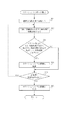
図1は、本実施例の二次元コードの検出に関するフローチャートである。なお、ここで、処理対象となる画像は2値画像である。したがって、多値画像を処理する場合は、予め二値化処理をおこなってから本フローチャートの処理を行う。 FIG. 1 is a flowchart regarding detection of a two-dimensional code according to the present embodiment. Here, the image to be processed is a binary image. Therefore, when processing a multi-valued image, the binarization process is performed in advance and then the process of this flowchart is performed.
まず、ステップ101において、画像内からロケーションシンボル(切り出しシンボル)を複数個検出する処理を実行する。
First, in
次に、ステップ102において、画像内の複数の上記ロケーションシンボルの組み合わせからQRコードを1乃至複数個検出し、当該検出したQRコードを出力する処理を実行する。
Next, in
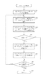
図1のステップ101の詳細について、図3のフローチャートを用いて説明する。図3のフローチャートでは、入力された2値画像内からロケーションシンボルを複数個検出し、ロケーションシンボル群として出力する処理が行われる。
Details of
ここで、図4に、図2のロケーションシンボル211近傍の拡大図を示し、この図を用いて説明を行う。
Here, FIG. 4 shows an enlarged view of the vicinity of the
ステップ301において、画像内から黒の画素塊(黒の連結画素群)を抽出する。画素塊の抽出は、黒画素にラベルを付けて画素塊を取り出すラベリング法や、黒画素塊の輪郭を追跡して取り出す輪郭追跡法など、公知の技術を用いることが可能である。ここでは、例えば、白画素に囲まれた黒画素塊401、403などが検出される。
In
ステップ302において、ステップ301で検出された全ての黒画素塊のうち、黒画素塊の内部に白画素塊と別の黒画素塊とを有する画素塊を検出する。そして、内部に別の黒画素塊を含む黒画素塊を処理対象として、ステップ303〜304の処理を行う。ステップ303〜304の処理は、内部に別の黒画素塊を有する画素塊全てに対して、順番に行われる。図4では、ステップ301で検出された黒画素塊401の内部に、別の黒画素塊402が含まれることが検出されるので、当該黒画素塊401を処理対象とする。
In
ステップ303では、外側の画素塊と内部の画素塊について、双方の画素数比がほぼ8:3であるか、各画素塊に外接する各外接矩形の1辺の比がほぼ7:3となるか、各画素塊に外接する各外接矩形の中心がほぼ等しいか、各画素塊に外接する各外接矩形の形状がほぼ正方形かを判定する。全ての条件を満たすと判断した場合、ステップ304に進む。全ての条件を満たさないと判断した場合、ステップ305に進む。
In
ステップ304では、前記条件を満たした外側の画素塊とその内部の画素塊(図4の例では、画素塊401と画素塊402)は、ロケーションシンボルとして記録される。ここでは、ロケーションシンボルの中心座標と大きさとを記録しておく。
In
ステップ305では、内部に別の黒画素塊を有する画素塊で、まだステップ303−304の処理を行っていない画素塊があるか判断し、もしあれば、ステップ302に戻ってその未処理の画素塊を対象にして、ステップ303の処理を行う。一方、内部に別の黒画素塊を有する画素塊全てに対して、ステップ303−304の処理を行ったと判断した場合は、ステップ306に進む。
In step 305, it is determined whether or not there is a pixel block having another black pixel block inside that has not yet been processed in steps 303-304. If there is, the process returns to
ステップ306では、ステップ304で記録された全てのロケーションシンボルの情報を出力する。
In
図1のステップ102の詳細を図5に示す。ここでは、ステップ306で出力されたロケーションシンボル情報を受け取り、当該ロケーションシンボル情報に基づいて、QRコードを探索して、検出されたQRコードに関する情報を出力する。
Details of
以下では、図2のロケーションシンボル211〜214に関する情報を、受け取ったロケーションシンボル情報の例として説明する。 Below, the information regarding the location symbols 211-214 of FIG. 2 is demonstrated as an example of the received location symbol information.
ステップ501で、受け取ったロケーションシンボル情報と同数のフラグ領域を確保し、全てのロケーションシンボルに対して使用フラグを対応付けて、全ての使用フラグを「未使用(OFF)」に初期化する。
In
ステップ502で、使用フラグがOFFで、未だ着目対象にしていないロケーションシンボル情報から任意に選択した1つのロケーションシンボルを着目対象にして、ステップ503からステップ508の処理を行う。
In
ステップ503では、ステップ502で着目したロケーションシンボルに着目して、近傍のロケーションシンボルを探査することにより、QRコードを構成する3つのロケーションシンボルがあるかどうか検索する。
In step 503, focusing on the location symbol focused in
ステップ504では、ステップ503の結果に基づき、QRコードを構成する3つのロケーションシンボルが検索されたかどうか判断し、検索されたならば、ステップ505に進む。検索されなかったならばステップ507に進む。
In
ステップ505では、ステップ504で検出した3つのロケーションシンボルが1つのQRコードを構成するとして当該ロケーションシンボルの組を記録する。
In
ステップ506では、それら3つのロケーションシンボルに対応するフラグを「使用(ON)」にセットする。
In
例えば、ロケーションシンボル211に着目してステップ503の処理を行うと、3つのロケーションシンボル211,212,213がQRコード203を構成すると検索される。そして、そのロケーションシンボルの組の情報がステップ505で記録され、ステップ506でロケーションシンボル211〜213に対応する使用フラグが「ON」にセットされる。
For example, when the processing of step 503 is performed with attention paid to the
ステップ507では、使用フラグがOFFで且つまだ着目していないロケーションシンボル(未処理のロケーションシンボル)があるかどうか判断し、あると判断した場合はステップ502に戻り、ないと判断した場合はステップ508に進む。
In
ステップ508では、ステップ505において記録された全てのQRコードの情報を出力して、図5の処理フローを終了する。
In
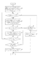
次に、図5のステップ504における、QRコードを構成するロケーションシンボル探索処理の詳細フローチャートを図6に示す。
Next, FIG. 6 shows a detailed flowchart of the location symbol search process that constitutes the QR code in
ステップ601では、まず、想定される最大サイズのQRコードの対角線の長さ情報を取得する。そして、着目ロケーションシンボルからの距離が当該取得した対角線の長さよりも短く、且つ、当該着目ロケーションシンボルの大きさとほぼ等しい大きさのロケーションシンボルを、QRコードを構成するロケーションシンボルの候補として決定する。対角線の長さ情報は、例えば、着目しているロケーションシンボルの外接矩形の大きさに基づいて、想定される最大サイズのQRコードを求め、そのQRコードの対角線の長さを算出することによって求めることができる。なお、本実施例では、ロケーションシンボルのサイズに対するQRコードのサイズが規格で定められているので、その規格に基づいて最大サイズの対角線の長さを算出することとする。しかしながら、これに限るものではなく、例えば、原稿内に含まれるQRコードのサイズが予め想定できる場合などでは、予め定めておいた値を対角線長さとして用いるようにしてもよい。 In step 601, first, the length information of the diagonal line of the QR code of the assumed maximum size is acquired. Then, a location symbol whose distance from the target location symbol is shorter than the length of the acquired diagonal line and is approximately equal to the size of the target location symbol is determined as a location symbol candidate constituting the QR code. The diagonal length information is obtained, for example, by obtaining a QR code of the maximum size assumed based on the size of the circumscribed rectangle of the location symbol of interest and calculating the diagonal length of the QR code. be able to. In this embodiment, since the size of the QR code with respect to the size of the location symbol is defined by the standard, the maximum diagonal length is calculated based on the standard. However, the present invention is not limited to this. For example, when the size of the QR code included in the document can be assumed in advance, a predetermined value may be used as the diagonal length.
例えば、図2の原稿において、着目ロケーションシンボルを211とした場合に、最大サイズの対角線の長さが221だったとする。すると、複数のロケーションシンボル群212〜215のうち、距離が対角線長さ221よりも短く、且つ、大きさがほぼ等しいロケーションシンボルを検索して、ロケーションシンボル212,213,214が候補となる。
For example, in the document of FIG. 2, when the target location symbol is 211, the length of the maximum diagonal line is 221. Then, among the plurality of
ステップ602では、ステップ601でロケーションシンボル候補が2つ以上求められたか判断し、2つ以上あると判断したならばステップ603に進む。一方、ロケーションシンボル候補が2つ以上存在しないと判断した場合、ステップ610に進む。 In step 602, it is determined whether two or more location symbol candidates are obtained in step 601, and if it is determined that there are two or more location symbol candidates, the process proceeds to step 603. On the other hand, if it is determined that there are not two or more location symbol candidates, the process proceeds to step 610.
ステップ610では、当該着目ロケーションシンボルを含むQRコードは存在しないと判断して、その判断した結果(QRコード無し)を出力する。 In step 610, it is determined that there is no QR code including the target location symbol, and the determination result (no QR code) is output.
ステップ603では、未検査のロケーションシンボル候補のうち、近いものから順に2つを取り出して検査対象とし、その検査対象のロケーションシンボル候補と着目ロケーションシンボルとを組み合わせたときにQRコードを構成するか検査する。すなわち、任意の2つのロケーションシンボル候補の組み合わせのうち、着目LSから近い組み合わせから順に検査対象として、QRコードを構成するものであるか否かを検査する。なお、3つのロケーションシンボルがQRコードを構成し得るか否かの検査としては、例えば、3つのロケーションシンボルを結ぶ形状が直角二等辺三角形を構成するか否かの検査や、3つのロケーションシンボルの間に黒画素塊があるか否かの検査などが行われる。また、QRコードとして認識可能か否かの検査も合わせて行うようにしても構わない。
In
ステップ604では、QRコードを構成すると判断した場合はステップ605へ進み、一方、QRコードを構成しないと判断した場合はステップ609へ進む。 In step 604, if it is determined that the QR code is to be configured, the process proceeds to step 605. On the other hand, if it is determined that the QR code is not to be configured, the process proceeds to step 609.
ステップ609では、他に未検査のロケーションシンボル候補の組み合わせがあるか否か判断し、あると判断した場合は、ステップ603へ戻って次のロケーションシンボル候補の組み合わせについて検査を行う。一方、他に未検査のロケーションシンボル候補がないと判断した場合は、ステップ610へ進む。
In
ステップ605では、ステップ604でQRコードを構成すると判断された2つのロケーションシンボル候補の1つを新たな着目ロケーションシンボルとして、当該検出されたQRコードよりも小さいQRコードを構成する3つのロケーションシンボルが存在するか検査する。すなわち、当該新たな着目ロケーションシンボルに対して、図6の処理を再帰的に行う。なお、より小さいQRコードを検出するための処理であるので、再帰的に行うときのステップ601では、その前に検出されたQRコードの1辺の長さよりも短く、該新たな着目ロケーションシンボルの大きさとほぼ等しい大きさのロケーションシンボルを候補とする。なお、より小さいQRコードがあった場合は、その再帰的に行われた図6の処理において、より小さいQRコードを構成する3つのロケーションシンボルが出力されることになる。
In
ステップ606では、より小さいQRコードがあったか否か判断する。より小さいQRコードがあったと判断した場合は、その2つのロケーションシンボル候補の組み合わせを検査済みとして、ステップ602に戻り、他のロケーションシンボル候補の組み合わせがあるか判断する。
In
一方、より小さいQRコードがなかったと判断した場合は、ステップ607に進む。ステップ607では、該2つのロケーションシンボル候補の両方について、ステップ605の検査を行ったか判断し、検査済みの場合はステップ608に進み、検査を行っていない場合はもう一方を新たな着目ロケーションシンボルとしてステップ605の処理に戻る。
On the other hand, if it is determined that there is no smaller QR code, the process proceeds to step 607. In step 607, it is determined whether or not the inspection in
ステップ608では、QRコードを構成するロケーションシンボルとして、当該3つのロケーションシンボル(着目LSとその検査対象LS候補)の組み合わせ情報を出力する。
In
このようにして検出されたQRコードに対してQRコード認識処理を行うと、認識結果を得ることができる。 When QR code recognition processing is performed on the QR code thus detected, a recognition result can be obtained.
以上説明したように、本実施形態では、複数のロケーションシンボル(切り出しシンボル)を検出し、そのロケーションシンボル間の距離とロケーションシンボルの大きさとに基づいて、QRコードを構成するロケーションシンボルの組み合わせを検出している。このように構成することにより、入力画像から、回転角度やサイズが異なっていても、複数のQRコードを検出できるようになる。 As described above, in this embodiment, a plurality of location symbols (cutout symbols) are detected, and a combination of location symbols constituting a QR code is detected based on the distance between the location symbols and the size of the location symbol. is doing. With this configuration, a plurality of QR codes can be detected from an input image even if the rotation angle and size are different.
Claims (8)
前記画像から複数のロケーションシンボルを検出するシンボル検出手段と、
前記検出された複数のロケーションシンボルの1つを着目し、当該着目したロケーションシンボルの大きさと当該着目したロケーションシンボルからの距離とに基づいて、前記検出された複数のロケーションシンボルの中から、当該着目したロケーションシンボルとともに前記二次元コードを構成するロケーションシンボルの候補を決定する決定手段と、
前記決定手段で決定された候補のうち、前記着目したロケーションシンボルに近いものから順に検査していくことにより、前記二次元コードを構成するロケーションシンボルの組み合わせを検出する組み合わせ検出手段と、
を備え、
前記組み合わせ検出手段は、更に、前記二次元コードを構成するロケーションシンボルについて、より小さい二次元コードを他のロケーションシンボルと構成しうるか否か判断し、より小さい二次元コードを構成しうると判断した場合は、更に他の候補との組み合わせを検査していくことを特徴とする画像処理装置。 An image processing apparatus for detecting a two-dimensional code including a predetermined number of location symbols from an image,
Symbol detecting means for detecting a plurality of location symbols from the image;
Focusing one of the plurality of locations symbols the detected, based on the distance from the size and the focus to location symbols of the interest the location symbol, from the detected plurality of locations symbols were, the attention Determining means for determining candidate location symbols constituting the two-dimensional code together with the location symbols ;
A combination detection means for detecting a combination of location symbols constituting the two-dimensional code by inspecting the candidates determined by the determination means in order from the closest to the focused location symbol ;
Equipped with a,
The combination detection unit further determines whether or not a smaller two-dimensional code can be configured with another location symbol for the location symbols constituting the two-dimensional code, and determines that a smaller two-dimensional code can be configured. In the case, the image processing apparatus is further characterized by inspecting combinations with other candidates .
シンボル検出手段が、前記画像から複数のロケーションシンボルを検出するシンボル検出ステップと、
決定手段が、前記検出された複数のロケーションシンボルの1つを着目し、当該着目したロケーションシンボルの大きさと当該着目したロケーションシンボルからの距離とに基づいて、前記検出された複数のロケーションシンボルの中から、当該着目したロケーションシンボルとともに前記二次元コードを構成するロケーションシンボルの候補を決定する決定ステップと、
検出手段が、前記決定ステップで決定された候補のうち、前記着目したロケーションシンボルに近いものから順に検査していくことにより、前記二次元コードを構成するロケーションシンボルの組み合わせを検出する組み合わせ検出ステップと、
を備え、
前記組み合わせ検出ステップでは、更に、前記二次元コードを構成するロケーションシンボルについて、より小さい二次元コードを他のロケーションシンボルと構成しうるか否か判断し、より小さい二次元コードを構成しうると判断した場合は、更に他の候補との組み合わせを検査していくことを特徴とする画像処理方法。 An image processing method for detecting a two-dimensional code including a predetermined number of location symbols from an image,
A symbol detecting step for detecting a plurality of location symbols from the image;
The determining means pays attention to one of the detected plurality of location symbols, and based on the size of the noticed location symbol and the distance from the noticed location symbol, A determination step of determining candidate location symbols constituting the two-dimensional code together with the focused location symbol ;
A combination detecting step for detecting a combination of location symbols constituting the two-dimensional code by detecting in order from a candidate closest to the focused location symbol among candidates determined in the determining step; ,
Equipped with a,
In the combination detection step, for the location symbols constituting the two-dimensional code, it is determined whether a smaller two-dimensional code can be configured with other location symbols, and it is determined that a smaller two-dimensional code can be configured. In the case, an image processing method characterized by further examining a combination with other candidates .
コンピュータを、
画像から複数のロケーションシンボルを検出するシンボル検出手段、
前記検出された複数のロケーションシンボルの1つを着目し、当該着目したロケーションシンボルの大きさと当該着目したロケーションシンボルからの距離とに基づいて、前記検出された複数のロケーションシンボルの中から、当該着目したロケーションシンボルとともに前記二次元コードを構成するロケーションシンボルの候補を決定する決定手段、
前記決定手段で決定された候補のうち、前記着目したロケーションシンボルに近いものから順に検査していくことにより、前記二次元コードを構成するロケーションシンボルの組み合わせを検出する組み合わせ検出手段、
として機能させ、更に、
前記組み合わせ検出手段では、更に、前記二次元コードを構成するロケーションシンボルについて、より小さい二次元コードを他のロケーションシンボルと構成しうるか否か判断し、より小さい二次元コードを構成しうると判断した場合は、更に他の候補との組み合わせを検査していくように、前記コンピュータを機能させるためのコンピュータプログラム。 A computer program for detecting a two-dimensional code including a predetermined number of location symbols from an image,
Computer
Symbol detection means for detecting a plurality of location symbols from an image;
Focusing one of the plurality of locations symbols the detected, based on the distance from the size and the focus to location symbols of the interest and location symbols, from among the detected plurality of locations symbols were, the attention Determining means for determining a location symbol candidate that constitutes the two-dimensional code together with the location symbol ;
A combination detection means for detecting a combination of location symbols constituting the two-dimensional code by inspecting the candidates determined by the determination means in order from the candidate closest to the focused location symbol ;
To function as, further,
The combination detection unit further determines whether or not a smaller two-dimensional code can be configured with another location symbol for the location symbols constituting the two-dimensional code, and determines that a smaller two-dimensional code can be configured. If, as further continue to examine the combination of the other candidates, because the computer program causes the computer to function.
Priority Applications (2)
| Application Number | Priority Date | Filing Date | Title |
|---|---|---|---|
| JP2007278961A JP5111055B2 (en) | 2007-10-26 | 2007-10-26 | Image processing apparatus, image processing method, and computer program |
| US12/257,173 US7922087B2 (en) | 2007-10-26 | 2008-10-23 | Image processing apparatus, image processing method, and computer program stored in storage medium |
Applications Claiming Priority (1)
| Application Number | Priority Date | Filing Date | Title |
|---|---|---|---|
| JP2007278961A JP5111055B2 (en) | 2007-10-26 | 2007-10-26 | Image processing apparatus, image processing method, and computer program |
Publications (2)
| Publication Number | Publication Date |
|---|---|
| JP2009110070A JP2009110070A (en) | 2009-05-21 |
| JP5111055B2 true JP5111055B2 (en) | 2012-12-26 |
Family
ID=40622798
Family Applications (1)
| Application Number | Title | Priority Date | Filing Date |
|---|---|---|---|
| JP2007278961A Expired - Fee Related JP5111055B2 (en) | 2007-10-26 | 2007-10-26 | Image processing apparatus, image processing method, and computer program |
Country Status (2)
| Country | Link |
|---|---|
| US (1) | US7922087B2 (en) |
| JP (1) | JP5111055B2 (en) |
Families Citing this family (7)
| Publication number | Priority date | Publication date | Assignee | Title |
|---|---|---|---|---|
| JP4724802B1 (en) * | 2010-07-30 | 2011-07-13 | 株式会社シフト | 2D code reader and program |
| JP4724801B1 (en) * | 2010-07-30 | 2011-07-13 | 株式会社シフト | 2D code reader and program |
| RU2543569C1 (en) * | 2011-10-10 | 2015-03-10 | Евон Коммьюникейшен Ко., Лтд. | Device and method for automatic recognition of qr-code |
| JP2013125335A (en) * | 2011-12-13 | 2013-06-24 | Toshiba Tec Corp | Code reader, sales registration device and program |
| CN106462785B (en) * | 2014-05-14 | 2018-09-14 | 共同印刷株式会社 | The analysis system of Quick Response Code and Quick Response Code |
| EP3136392A1 (en) | 2015-08-25 | 2017-03-01 | Thomson Licensing | Method and system for embedding and retrieving information through marker transformation |
| US10235547B2 (en) | 2016-01-26 | 2019-03-19 | Hand Held Products, Inc. | Enhanced matrix symbol error correction method |
Family Cites Families (9)
| Publication number | Priority date | Publication date | Assignee | Title |
|---|---|---|---|---|
| JP2867904B2 (en) * | 1994-12-26 | 1999-03-10 | 株式会社デンソー | 2D code reader |
| JPH0944592A (en) * | 1995-05-23 | 1997-02-14 | Olympus Optical Co Ltd | Information reproduction system |
| JP3458737B2 (en) * | 1998-11-27 | 2003-10-20 | 株式会社デンソー | Reading method of two-dimensional code and recording medium |
| JP3508836B2 (en) * | 1999-06-22 | 2004-03-22 | インターナショナル・ビジネス・マシーンズ・コーポレーション | Apparatus and method for detecting approximate position of two-dimensional code |
| JP4419269B2 (en) * | 2000-04-18 | 2010-02-24 | 富士通株式会社 | Two-dimensional code extraction method |
| JP4301775B2 (en) * | 2002-07-18 | 2009-07-22 | シャープ株式会社 | Two-dimensional code reading device, two-dimensional code reading method, two-dimensional code reading program, and recording medium for the program |
| KR100828539B1 (en) * | 2005-09-20 | 2008-05-13 | 후지제롯쿠스 가부시끼가이샤 | Detection method of two dimensional code, detection device thereof, and storage medium having detection program storaged therein |
| JP4911340B2 (en) * | 2006-02-10 | 2012-04-04 | 富士ゼロックス株式会社 | Two-dimensional code detection system and two-dimensional code detection program |
| US7546950B2 (en) * | 2006-03-28 | 2009-06-16 | Seiko Epson Corporation | Method and apparatus for locating and decoding a two-dimensional machine-readable symbol |
-
2007
- 2007-10-26 JP JP2007278961A patent/JP5111055B2/en not_active Expired - Fee Related
-
2008
- 2008-10-23 US US12/257,173 patent/US7922087B2/en not_active Expired - Fee Related
Also Published As
| Publication number | Publication date |
|---|---|
| US20090121024A1 (en) | 2009-05-14 |
| JP2009110070A (en) | 2009-05-21 |
| US7922087B2 (en) | 2011-04-12 |
Similar Documents
| Publication | Publication Date | Title |
|---|---|---|
| JP5111055B2 (en) | Image processing apparatus, image processing method, and computer program | |
| JP2835274B2 (en) | Image recognition device | |
| CN107315011B (en) | Image processing apparatus, image processing method, and storage medium | |
| JP6323437B2 (en) | 10-finger fingerprint card input device, 10-finger fingerprint card input method, and storage medium | |
| JPH07141463A (en) | Detection of mechanically printed amount of money in binary-coded image | |
| JP2008047664A (en) | Pattern inspecting apparatus and semiconductor inspecting system | |
| US10643097B2 (en) | Image processing apparatuses and non-transitory computer readable medium | |
| US8913852B2 (en) | Band-based patch selection with a dynamic grid | |
| JP2010071951A (en) | Visual inspection device and visual inspection method | |
| JP6496159B2 (en) | Pattern inspection apparatus and pattern inspection method | |
| CN111784672A (en) | Defect detection method and device, electronic equipment and readable storage medium | |
| US20190306415A1 (en) | Image processing apparatus, image processing method, and storage medium | |
| US6757421B1 (en) | Method and apparatus for detecting defects | |
| JP5993100B2 (en) | Image processing apparatus and specific figure detection method | |
| JP2009150656A (en) | Method and device for pattern inspection | |
| JP2001099625A (en) | Device and method for pattern inspection | |
| JP7478628B2 (en) | Image processing device, control method, and control program | |
| JP4381445B2 (en) | Image characteristic determination processing apparatus, image characteristic determination processing method, program for executing the method, and computer-readable storage medium storing the program | |
| JP4094240B2 (en) | Image characteristic determination processing apparatus, image characteristic determination processing method, program for executing the method, and computer-readable storage medium storing the program | |
| JP2005242825A (en) | Business form reading device and business form direction determination method by business form reading device | |
| JP5107100B2 (en) | Character recognition method, character recognition device, and character recognition program | |
| JP2023024148A (en) | Image processing apparatus, image processing method, and image processing program | |
| JP2002015323A (en) | Document image layout distinguishing method and device thereof | |
| JP2022184098A (en) | Image processing device, image processing method and program | |
| JP5185072B2 (en) | Frame detection method, frame detection apparatus, and frame detection program |
Legal Events
| Date | Code | Title | Description |
|---|---|---|---|
| RD04 | Notification of resignation of power of attorney |
Free format text: JAPANESE INTERMEDIATE CODE: A7424 Effective date: 20100201 |
|
| RD01 | Notification of change of attorney |
Free format text: JAPANESE INTERMEDIATE CODE: A7421 Effective date: 20100630 |
|
| A621 | Written request for application examination |
Free format text: JAPANESE INTERMEDIATE CODE: A621 Effective date: 20101018 |
|
| A977 | Report on retrieval |
Free format text: JAPANESE INTERMEDIATE CODE: A971007 Effective date: 20120614 |
|
| A131 | Notification of reasons for refusal |
Free format text: JAPANESE INTERMEDIATE CODE: A131 Effective date: 20120626 |
|
| A521 | Request for written amendment filed |
Free format text: JAPANESE INTERMEDIATE CODE: A523 Effective date: 20120823 |
|
| TRDD | Decision of grant or rejection written | ||
| A01 | Written decision to grant a patent or to grant a registration (utility model) |
Free format text: JAPANESE INTERMEDIATE CODE: A01 Effective date: 20120911 |
|
| A01 | Written decision to grant a patent or to grant a registration (utility model) |
Free format text: JAPANESE INTERMEDIATE CODE: A01 |
|
| A61 | First payment of annual fees (during grant procedure) |
Free format text: JAPANESE INTERMEDIATE CODE: A61 Effective date: 20121009 |
|
| FPAY | Renewal fee payment (event date is renewal date of database) |
Free format text: PAYMENT UNTIL: 20151019 Year of fee payment: 3 |
|
| R151 | Written notification of patent or utility model registration |
Ref document number: 5111055 Country of ref document: JP Free format text: JAPANESE INTERMEDIATE CODE: R151 |
|
| FPAY | Renewal fee payment (event date is renewal date of database) |
Free format text: PAYMENT UNTIL: 20151019 Year of fee payment: 3 |
|
| LAPS | Cancellation because of no payment of annual fees |