JP5108882B2 - Venous catheter insertion device - Google Patents
Venous catheter insertion device Download PDFInfo
- Publication number
- JP5108882B2 JP5108882B2 JP2009518416A JP2009518416A JP5108882B2 JP 5108882 B2 JP5108882 B2 JP 5108882B2 JP 2009518416 A JP2009518416 A JP 2009518416A JP 2009518416 A JP2009518416 A JP 2009518416A JP 5108882 B2 JP5108882 B2 JP 5108882B2
- Authority
- JP
- Japan
- Prior art keywords
- needle
- guide wire
- guidewire
- catheter
- access needle
- Prior art date
- Legal status (The legal status is an assumption and is not a legal conclusion. Google has not performed a legal analysis and makes no representation as to the accuracy of the status listed.)
- Active
Links
- 0 C#CC1=*CCCC1 Chemical compound C#CC1=*CCCC1 0.000 description 1
Images


Description
本発明は、患者の静脈又は動脈に静脈カテーテルを挿入し、また配置するための装置及び方法に関する。 The present invention relates to an apparatus and method for inserting and placing a venous catheter in a patient's vein or artery.
以下の特許文献は、従来の静脈カテーテル挿入装置及び/又はシリンジ及び針のための安全装置について記載する。
Haining−EP0051571OA1 静脈カテーテル及び挿入装置
Haining−EP0051571OB1 静脈カテーテル及び挿入装置
Haining−US05019049 静脈カテーテル及び挿入装置
Haining−US05176650 静脈カテーテル及び挿入装置
Chang−EP00567321A2 ニードルガードを備えた静脈カテーテル
Mahukar−EP00652020B1 格納式皮下注射針組立品
Mahukar−EP00910988A1 血液標本収集アセンブリ
Mahukar−US05891105 皮下注射針組立品
DeWitt−US03572334 静脈カテーテル配置ユニット
van Heugten−EP00750916A2 保護針格納容器
Botich−EP00942761B1 格納針を備えた医療装置
Botich−EP01075850B1 静脈カテーテル挿入のための装置
Botich et al−US05800395 格納針を備えた医療装置
Botich et al−US06436070 格納針を備えたカテーテル挿入装置
Botich et al−US23060760A1 格納針を備えたカテーテル挿入装置
Botich et al−WO OOOl 2160Al 格納針を備えた流体注入装置
Botich−WO09632981 Al 静脈カテーテル挿入のための安全探り針
Botich−WO09824494A1 格納式針を備えた医療装置
Shue−EP01457229A1 静脈カテーテル挿入装置
Shue−US24106903A1 静脈カテーテル挿入装置
Harautuneian−US03592192 穿刺カニューレの外側に嵌り込んだカテーテルを用いた静脈カテーテル装置
Harautuneian−US03610240 穿刺カニューレの内側に嵌り込んだカテーテルを備えた静脈カテーテル装置
Poncy et al−US04037600 カテーテル配置システム
Hession−US04292970 静脈カテーテル始動装置
McDonald−US04834718 安全針装置
McDonald−US04944725 安全針装置
Vining et al−US04909793 格納式探り針を用いた静脈カテーテル装置
Carrell et al−US04944728 静脈カテーテル配置装置
Kaufman−US04966589 静脈カテーテル配置装置
Shields−US05007901 静脈カテーテル挿入装置
Haughton et al−US05562629 ハンドルからカテーテルを解放する際に針の後退を可能にするハンドル、針及び解除式固定機構を利用したカテーテル配置システム
Flumene et al−US05562634 自動格納ニードルガイドを備えた静脈カテーテル
Isaacson−US05573510 自動格納針を備えた安全静脈カテーテル・アセンブリ
Isaacson−US06056726 自己収容した安全静脈カテーテル挿入装置
Isaacson−WO09523003A1 自己収容した安全静脈カテーテル挿入装置
Huang−US05891098 安全静脈カテーテル
Bhitiyakul−US05941854 静脈カテーテル
Dysarz−US05997507 付勢ばね硬化針格納式のIVテーテル
Dysarz−US06193690 IVカテーテルのための傾斜面掛け金装置
Greene et al−US06221047 安全静脈カテーテル・アセンブリ及び針を用いて使用するための方法
Greene et al−US06689102 安全静脈カテーテル・アセンブリ
Greene et al−US06695814 安全静脈カテーテル・アセンブリ及び針を用いて使用するための方法
Greene et al−US21014786A1 安全静脈カテーテル・アセンブリ及び針を用いて使用するための方法
Greene et al−US22165497A1 安全静脈カテーテル・アセンブリ
Greene et al−WO00006226A1 安全静脈カテーテル・アセンブリ及び針を用いて使用するための方法
Chang−US06322537 安全静脈カテーテル
Pressly, Sr. et al−US06620136 格納式IVカテーテル配置装置
Pressly, Sr. et al−WO00047256A1 格納式IVカテーテル配置装置
Hoffman et al−US06730062 取外し不能な格納針を備えた安全カテーテル
Hoffman et al−US23073956A1 取外し不能な格納針を備えた安全カテーテル
Brustowicz−US24267204A1 静脈カテーテル・アセンブリにおいて使用するためのオン・デマンド針の保持及び固定機構
Garcia Andreo−WO03043686A1 流れ調整/自動バルブの静脈カテーテル
Sircom−WO09222344A1 静脈カテーテルの配置のためのニードルガード
Ogle−WO09519193 Al 格納式静脈穿刺カテーテルの針及び容器
Rohrbough et al−WO09705912A2 格納式静脈穿刺カテーテルの針及び容器
Hwang−WO09721458A1 柔軟な拡張装置及び針先端の保護装置を備えた静脈カテーテル
The following patent documents describe conventional venous catheter insertion devices and / or safety devices for syringes and needles.
Haining-EP0051571OA1 Intravenous catheter and insertion device
Haining-EP0051571OB1 Intravenous catheter and insertion device
Haining-US05019049 Intravenous catheter and insertion device
Haining-US05176650 Intravenous catheter and insertion device
Chang-EP00567321A2 Venous catheter with needle guard
Mahukar-EP00652020B1 Retractable hypodermic needle assembly
Mahukar-EP00910988A1 Blood specimen collection assembly
Mahukar-US05891105 hypodermic needle assembly
DeWitt-US03572334 IV catheter placement unit
van Heugten-EP00750916A2 Protection needle storage
Botich-EP00942761B1 Medical device with retractable needle
Botich-EP01075850B1 Device for venous catheter insertion
Botich et al-US05800395 Medical device with retractable needle
Botich et al-US06436070 Catheter insertion device with retractable needle
Botich et al-US23060760A1 Catheter insertion device with retractable needle
Botich et al-WO OOOl 2160Al Fluid injection device with retractable needle
Botich-WO09632981 Al Safety probe for venous catheter insertion
Botich-WO09824494A1 Medical device with retractable needle
Shue-EP01457229A1 Intravenous catheter insertion device
Shue-US24106903A1 Intravenous catheter insertion device
Harautuneian-US03592192 Intravenous catheter device using a catheter fitted outside the puncture cannula
Harautuneian-US03610240 Intravenous catheter device with a catheter fitted inside the puncture cannula
Poncy et al-US04037600 Catheter placement system
Hession-US04292970 Intravenous catheter starter
McDonald-US04834718 Safety needle device
McDonald-US04944725 Safety needle device
Vining et al-US04909793 Intravenous catheter device with retractable probe
Carrell et al-US04944728 Intravenous catheter placement device
Kaufman-US04966589 Intravenous catheter placement device
Shields-US05007901 Intravenous catheter insertion device
Haughton et al-US05562629 Catheter placement system utilizing a handle, needle and a releasable locking mechanism that allows the needle to be retracted when releasing the catheter from the handle
Flumene et al-US05562634 Intravenous catheter with self retracting needle guide
Isaacson-US05573510 Safe venous catheter assembly with automatic retractable needle
Isaacson-US06056726 Self-contained safety venous catheter insertion device
Isaacson-WO09523003A1 Self-contained safety venous catheter insertion device
Huang-US05891098 Safety venous catheter
Bhitiyakul-US05941854 venous catheter
Dysarz-US05997507 Energizing spring hardening needle retractable IV tetel
Dysarz-US06193690 Inclined Hasp Device for IV Catheter
Greene et al-US06221047 Safety venous catheter assembly and method for use with a needle
Greene et al-US06689102 Safety venous catheter assembly
Greene et al-US06695814 Safety venous catheter assembly and method for use with a needle
Greene et al-US21014786A1 Safe venous catheter assembly and method for use with a needle
Greene et al-US22165497A1 Safe venous catheter assembly
Greene et al-WO00006226A1 Safe venous catheter assembly and method for use with a needle
Chang-US06322537 Safety venous catheter
Pressly, Sr. et al-US06620136 Retractable IV catheter placement device
Pressly, Sr. et al-WO00047256A1 Retractable IV catheter placement device
Hoffman et al-US06730062 Safety catheter with non-removable retractable needle
Hoffman et al-US23073956A1 Safety catheter with a non-removable retractable needle
Brustowicz-US24267204A1 On-demand needle retention and fixation mechanism for use in venous catheter assemblies
Garcia Andreo-WO03043686A1 Flow-regulating / automatic valve venous catheter
Sircom-WO09222344A1 Needle guard for placement of venous catheters
Ogle-WO09519193 Al Needle and container for retractable venipuncture catheter
Rohrbough et al-WO09705912A2 Needle and container for retractable venipuncture catheter
Hwang-WO09721458A1 Intravenous catheter with flexible dilator and needle tip protector
本発明の装置及び方法は、患者の静脈又は動脈へのカテーテルの安全な配置を容易にし、それは、小さく、入り組み、壊れやすく、傷付きやすく且つ/又は管を位置付けることが困難な場合に、特に重要である。装置及び方法は、静脈カテーテルを配置した後に、針による偶発的な刺し傷や汚染に対する保護をも提供する。 The device and method of the present invention facilitates the safe placement of a catheter in a patient's vein or artery, which is small, intricate, fragile, vulnerable and / or difficult to position the tube. Of particular importance. The device and method also provide protection against accidental puncture and contamination with a needle after placement of a venous catheter.
本発明の一実施の形態において、内部空間を有する筐体と、内部空間に対してスライド移動可能なアクセス針と、アクセス針によって支持されるともに、アクセス針に対してスライド移動可能なガイドワイヤと、ガイドワイヤを内部空間に対して移動させるために、筐体に対して移動可能なガイドワイヤに取り付けられたハンドルと、ガイドワイヤのアクセス針に対する動きを制限するために、ハンドルに取り付けられた抑制部材とを備えたカテーテル挿入装置が提供される。 In one embodiment of the present invention, a housing having an internal space, an access needle that is slidable relative to the internal space, a guide wire that is supported by the access needle and is slidable relative to the access needle, A handle attached to the guide wire movable relative to the housing to move the guide wire relative to the interior space, and a restraint attached to the handle to restrict movement of the guide wire relative to the access needle A catheter insertion device comprising a member is provided.
一形態において、ハンドルに取り付けられた抑制部材は、アクセス針に対するガイドワイヤの基端側への動きを制限する。他の形態において、アクセス針は、筐体を超えて伸びるアクセス針の部分の中に、血液逆流表示部を備える。他の形態において、アクセス針は、アクセス針がカテーテルの中に配置される時にカテーテル末端において可視化する血液逆流表示部を備える。更なる形態において血液逆流表示部は、アクセス針の末端の側壁に開口部を備える。 In one form, the restraining member attached to the handle limits the proximal movement of the guidewire relative to the access needle. In another form, the access needle comprises a blood reflux indicator in the portion of the access needle that extends beyond the housing. In another form, the access needle includes a blood reflux indicator that is visualized at the distal end of the catheter when the access needle is placed into the catheter. In a further form, the blood reflux indicator comprises an opening in the distal sidewall of the access needle.
他の形態において、カテーテル挿入装置は、ガイドワイヤ及びアクセス針の1つ又は両方を自動的に引き込むように設計して、適用された付勢要素と解放ボタンをも含む。更なる形態において、付勢要素及び解放ボタンは、ガイドワイヤとアクセス針とを同時に内部空間へ引き込むように設計して、適用される。他の形態において、付勢要素及び解放ボタンは、ガイドワイヤとアクセス針とを順に引き込むように設計して、適用される。一実施の形態において、カテーテル挿入装置は、内部空間の中のアクセス針又はガイドワイヤの末端側への移動を制限する、内部空間の中の抑制部材をも含む。代替の一形態において、抑制部材は、カテーテルを挿入するために使用した後にアクセス針又はガイドワイヤが内部空間に引き込まれた後、アクセス針又はガイドワイヤの末端側への移動を制限する。他の代替の形態において、抑制部材は、アクセス針又はガイドワイヤが内部空間に完全に引き込まれたままとなるように、アクセス針又はガイドワイヤの末端側への移動を制限する。 In another form, the catheter insertion device is also designed to automatically retract one or both of the guidewire and access needle and also includes an applied biasing element and a release button. In a further form, the biasing element and the release button are designed and applied to retract the guidewire and access needle into the interior space simultaneously. In other forms, the biasing element and release button are designed and applied to retract the guidewire and access needle in turn. In one embodiment, the catheter insertion device also includes a restraining member in the interior space that limits distal movement of the access needle or guidewire in the interior space. In an alternative form, the restraining member limits the distal movement of the access needle or guide wire after the access needle or guide wire is retracted into the interior space after use to insert the catheter. In other alternative forms, the restraining member limits the distal movement of the access needle or guidewire so that the access needle or guidewire remains fully retracted into the interior space.
カテーテル挿入装置の一実施の形態において、内部空間は、カテーテルの挿入後にガイドワイヤ及びアクセス針の全てを収容する寸法で設計される。他の形態において、ガイドワイヤは、第1直径を有する第1部分と、縮小部分と、第1直径よりも小さい第2直径を有する第2部分とを備える。また更なる形態において、第1直径及び第2直径は、アクセス針の内径より小さい。また他の形態において、第2部分の末端部は、1つ以上の全半径末端部、ガイドワイヤと同じ半径の半球部、ガイドワイヤ又は末端部とは異なる半球部、又は、第1直径と同じ直径を有する末端部とを備える。代替の一形態において、ガイドワイヤは、編み上げ構造を有する。他の代替の形態において、カテーテル挿入装置は、ハンドルの移動を制限するための筐体内のガイドチャネルと、ガイドチャネルに隣接する保持チャネルとを備え、保持チャネルは、ハンドルが保持チャネル内にある時に、ハンドルの移動を阻止するように設けられる。一形態において、抑制部材によって、ガイドワイヤの基端側への移動が阻止され、保持チャネルによって、ガイドワイヤの末端側への移動が阻止される。他の形態において、内部空間内に固定されたプーリーがあり、ガイドワイヤが内部空間へ容易に移動できるように設けられる。 In one embodiment of the catheter insertion device, the interior space is designed with dimensions that accommodate all of the guidewire and access needle after insertion of the catheter. In another form, the guidewire comprises a first portion having a first diameter, a reduced portion, and a second portion having a second diameter that is smaller than the first diameter. In yet a further form, the first diameter and the second diameter are smaller than the inner diameter of the access needle. In yet other embodiments, the distal end of the second portion has one or more full radius distal ends, a hemispherical portion having the same radius as the guidewire, a hemispherical portion different from the guidewire or distal end, or the same as the first diameter. And a distal end having a diameter. In an alternative form, the guidewire has a braided structure. In another alternative form, the catheter insertion device comprises a guide channel in the housing for restricting movement of the handle and a retention channel adjacent to the guide channel, the retention channel being when the handle is in the retention channel. , Provided to prevent movement of the handle. In one form, the restraining member prevents movement of the guide wire to the proximal side, and the retention channel prevents movement of the guide wire to the distal side. In another form, there is a pulley fixed in the interior space and the guide wire is provided so that it can be easily moved into the interior space.
他の実施の形態において、内部空間を有する筐体を備えるカテーテル挿入装置と、末端部から基端部へと伸びるルーメンを形成する末端部と基端部と内壁部とを有するアクセス針と、内部空間に対してスライド移動可能なアクセス針と、アクセス針ルーメンと連通するアクセス針側壁の開口部と、アクセス針によって支持されるガイドワイヤとが備えられる。他の形態において、カテーテル挿入装置は、ガイドワイヤに取り付けられ、ガイドワイヤが開口部へ移動することを阻止するように設けられた抑制部材をも含む。一形態において、ガイドワイヤに取り付けられる抑制部材があり、ガイドワイヤが開口部の末端側のアクセス針の中に位置付けられる場合、抑制部材によって、開口部へ向けたガイドワイヤの基端側への移動が制限される。他の代替の形態において、アクセス針ルーメンは、アクセス針ルーメンに対するガイドワイヤの方向性を維持するガイドワイヤの断面形状を有する。一形態において、アクセス針ルーメンは、非円形の断面形状を有する。他の形態において、アクセス針ルーメンは、楕円形の断面形状を有する。他の形態において、アクセス針ルーメンに対するガイドワイヤの方向性を維持するために、アクセス針側壁内に形成される機構も備える。代替の一形態において、機構は溝である。一形態において、アクセス針側壁部の開口部は、アクセス針の末端部の基端側に位置付けられる。他の代替の形態において、アクセス針側壁部の開口部は、筐体末端側に位置付けられる。他の代替の形態において、アクセス針は、アクセス針内で非コイル状になるガイドワイヤを含む。他の代替の形態において、ガイドワイヤは、アクセス針内でコイル状である。一形態において、ガイドワイヤは、アクセス針ルーメン内で少なくとも半回転するようなコイル状である。他の形態において、ガイドワイヤは、アクセス針ルーメン内で一回転以上するようなコイル状である。また他の形態において、ガイドワイヤは、アクセス針の中にある。他の形態において、ガイドワイヤは、アクセス針に平行である。一実施の形態において、アクセス針によって支持されるガイドワイヤチャネルも備える。 In another embodiment, a catheter insertion device comprising a housing having an internal space, an access needle having a distal end, a proximal end, and an inner wall forming a lumen extending from the distal end to the proximal end; An access needle that is slidable with respect to the space, an opening in the side wall of the access needle that communicates with the access needle lumen, and a guide wire supported by the access needle are provided. In another form, the catheter insertion device also includes a restraining member attached to the guide wire and provided to prevent the guide wire from moving into the opening. In one form, if there is a restraining member attached to the guide wire and the guide wire is positioned in the access needle distal to the opening, the restraining member causes the guide wire to move proximally toward the opening. Is limited. In another alternative, the access needle lumen has a guidewire cross-sectional shape that maintains the orientation of the guidewire relative to the access needle lumen. In one form, the access needle lumen has a non-circular cross-sectional shape. In other forms, the access needle lumen has an elliptical cross-sectional shape. In another form, a mechanism formed in the access needle sidewall is also provided to maintain the orientation of the guidewire relative to the access needle lumen. In an alternative form, the mechanism is a groove. In one form, the opening in the access needle sidewall is positioned proximal to the distal end of the access needle. In another alternative, the access needle side wall opening is positioned distal to the housing. In other alternative forms, the access needle includes a guide wire that becomes non-coiled within the access needle. In another alternative form, the guidewire is coiled within the access needle. In one form, the guidewire is coiled such that it rotates at least half a turn within the access needle lumen. In another form, the guidewire is coiled such that it makes one or more revolutions within the access needle lumen. In yet another form, the guidewire is in the access needle. In other forms, the guidewire is parallel to the access needle. In one embodiment, a guidewire channel supported by the access needle is also provided.
本発明のカテーテル挿入装置の他の実施の形態において、内部空間及び長軸を有する筐体と、カテーテルに係合した場合に筐体長軸をカテーテルの長軸にオフセットする筐体末端部の機構と、機構を通過し、持針器に取り付けられたアクセス針とが備えられ、持針器は、内部空間に対してスライド移動可能であり、アクセス針は、機構に対してスライド移動可能である。代替の一形態において、筐体末端部の機構がカテーテルに係合する場合、筐体長軸は、180度未満の角度を形成するように、カテーテルの長軸を形成する。代替の一形態において、筐体末端部の機構がカテーテルに係合する場合、筐体長軸は、60度より小さい角度を形成するように、カテーテルの長軸からオフセットされる。他の代替の形態において、筐体末端部の機構がカテーテルに係合する場合、筐体長軸は、45度より小さい角度を形成するように、カテーテルの長軸からオフセットされる。他の代替の形態において、アクセス針によって支持され、アクセス針に対して移動可能なガイドワイヤも備える。他の代替の形態において、内部空間に対してガイドワイヤを移動させるために、筐体に対して移動可能なガイドワイヤに取り付けられるハンドルも備える。他の代替の形態において、アクセス針に対してガイドワイヤの動きを制限するために、ハンドルに取り付けられた抑制部材も備える。一形態において、アクセス針及びガイドワイヤが内部空間に引き込まれた場合に、ガイドワイヤ及びアクセス針は、筐体長軸に実質的に平行に引き込まれる。他の形態において、ガイドワイヤは、アクセス針の中に配置される。他の形態において、ガイドワイヤは、アクセス針に平行である。 In another embodiment of the catheter insertion device of the present invention, a housing having an internal space and a long axis, and a mechanism at the end of the housing for offsetting the housing long axis to the long axis of the catheter when engaged with the catheter, An access needle that passes through the mechanism and is attached to the needle holder, the needle holder is slidable relative to the internal space, and the access needle is slidable relative to the mechanism. In an alternative form, when the housing end feature engages the catheter, the housing major axis forms the major axis of the catheter so as to form an angle of less than 180 degrees. In an alternative form, when the housing end feature engages the catheter, the housing long axis is offset from the long axis of the catheter to form an angle of less than 60 degrees. In another alternative, when the housing end feature engages the catheter, the housing long axis is offset from the long axis of the catheter to form an angle of less than 45 degrees. In another alternative, a guide wire supported by the access needle and movable relative to the access needle is also provided. In another alternative form, a handle attached to the guide wire movable relative to the housing is also provided for moving the guide wire relative to the interior space. In another alternative form, a restraining member attached to the handle is included to limit the movement of the guide wire relative to the access needle. In one form, when the access needle and guide wire are retracted into the interior space, the guide wire and access needle are retracted substantially parallel to the housing major axis. In other forms, the guidewire is placed in the access needle. In other forms, the guidewire is parallel to the access needle.
本発明のカテーテル挿入装置の他の実施の形態において、内部空間を有する筐体と、内部空間に相対的にスライド移動可能なアクセス針と、アクセス針によって支持され、アクセス針に相対的に移動可能なガイドワイヤと、ガイドワイヤの少なくとも部分が内部空間に留まるように、ハンドルの移動が制限されたガイドワイヤに取り付けられたハンドルとが備えられる。他の代替の形態において、解放時に内部空間内で持針器を基端側へ移動させるように設計して、適用される付勢要素も備えられる。一形態において、付勢要素は、解放時に内部空間内でガイドワイヤを基端側へ移動させるように設計して、適用される。一形態において、付勢要素は、解放時に針を移動させ、それによって、針が完全に内部空間内にあるように設計して、適用される。他の形態において、付勢要素は、ガイドワイヤを移動させ、ガイドワイヤの全長が完全に内部空間内にあるように設計して、適用される。他の代替の形態において、アクセス針又はガイドワイヤが抑制装置の基端側へ移動した場合に、内部空間内でアクセス針又はガイドワイヤが末端側へ移動することを制限する内部空間内の抑制部材をも備える。一形態において、ガイドワイヤの一端部は、筐体に固定される。一形態において、ガイドワイヤの一端部は、ガイドワイヤがアクセス針の末端部を超えて伸長する時、内部空間内に拘束される。一形態において、ガイドワイヤは、アクセス針の中に配置される。他の形態において、ガイドワイヤは、アクセス針と平行に配置される。 In another embodiment of the catheter insertion device of the present invention, a housing having an internal space, an access needle that is slidable relative to the internal space, supported by the access needle, and relatively movable to the access needle And a handle attached to the guide wire with limited movement of the handle so that at least a portion of the guide wire remains in the interior space. In another alternative form, a biasing element is also provided that is designed and applied to move the needle holder proximally within the interior space upon release. In one form, the biasing element is designed and applied to move the guidewire proximally within the interior space upon release. In one form, the biasing element is applied with a design that moves the needle upon release, so that the needle is completely within the interior space. In another form, the biasing element is applied by moving the guidewire and designing it so that the entire length of the guidewire is completely within the interior space. In another alternative form, the restraining member in the interior space that restricts the access needle or guidewire from moving distally in the interior space when the access needle or guidewire moves to the proximal side of the restraining device. Is also provided. In one form, the one end part of a guide wire is fixed to a housing | casing. In one form, one end of the guidewire is constrained within the interior space when the guidewire extends beyond the distal end of the access needle. In one form, the guidewire is placed in the access needle. In other forms, the guidewire is disposed parallel to the access needle.
本発明のカテーテル挿入装置の他の実施の形態において、内部空間を有する筐体と、内部空間に相対的にスライド移動可能なアクセス針と、アクセス針に取り付けられるガイドワイヤチャネルと、ガイドワイヤチャネルによって支持され、ガイドワイヤチャネルに対して移動可能なガイドワイヤと、ガイドワイヤに取り付けられるハンドルとを備え、ハンドルが移動することによって、サポートチャネルに対してガイドワイヤが移動する。一形態において、ハンドルの移動が制限され、その結果、ガイドワイヤの少なくとも一部は、常に内部空間に留まる。他の形態において、自動的に1つ以上のガイドワイヤ及びアクセス針を引き込むように、設計して、適用される付勢要素と解放ボタンとが備えられる。他の形態において、内部空間内のアクセス針又はガイドワイヤの末端側への移動を制限する内部空間内の抑制部材も備えられる。一形態において、ガイドワイヤチャネルの末端部は、アクセス針の末端部に隣接する。他の形態において、ガイドワイヤチャネルは、アクセス針の上部にある。他の形態において、ガイドワイヤチャネルは、アクセス針の底部にある。他の形態において、ガイドワイヤは、アクセス針ルーメンを通過せずに、ガイドワイヤチャネルの末端部から排出される。また他の形態において、ガイドワイヤは、ガイドワイヤチャネルの末端部から、アクセス針ルーメンの一部を通って排出される。他の形態において、ガイドワイヤチャネルは、アクセス針ルーメンの中でアクセス針に取り付けられる。 In another embodiment of the catheter insertion device of the present invention, a housing having an internal space, an access needle that is slidable relative to the internal space, a guide wire channel attached to the access needle, and a guide wire channel A guide wire that is supported and movable relative to the guide wire channel, and a handle attached to the guide wire, the guide wire moves relative to the support channel as the handle moves. In one form, the movement of the handle is limited so that at least a portion of the guidewire always remains in the interior space. In another form, biasing elements and release buttons are provided that are designed and applied to automatically retract one or more guidewires and access needles. In another form, a restraining member in the interior space that limits the distal movement of the access needle or guidewire in the interior space is also provided. In one form, the distal end of the guidewire channel is adjacent to the distal end of the access needle. In other forms, the guidewire channel is at the top of the access needle. In another form, the guidewire channel is at the bottom of the access needle. In other forms, the guidewire is expelled from the distal end of the guidewire channel without passing through the access needle lumen. In yet another form, the guidewire is discharged from the distal end of the guidewire channel through a portion of the access needle lumen. In another form, the guidewire channel is attached to the access needle within the access needle lumen.
本発明の他の実施の形態において、カテーテルを血管に導入する種々の方法であって、実質的に筐体内に含まれるガイドワイヤを血管に挿入するステップと、ガイドワイヤを超えて、血管に前進するステップと、血管から完全に筐体へガイドワイヤを引き込むステップとを含む。代替の一形態において、血管に挿入された針に沿ってガイドワイヤを前進させるステップは、挿入ステップの前に実行される。代替の一形態において、血管に挿入された針に沿ってガイドワイヤを前進させるステップは、挿入ステップの前に実行される。他の代替の形態において、ガイドワイヤを血管内でコイル状に巻くステップは、挿入ステップの後に実行される。 In other embodiments of the present invention, various methods for introducing a catheter into a blood vessel, the step of inserting a guide wire substantially contained within a housing into the blood vessel, and advancement into the blood vessel beyond the guide wire And drawing the guide wire completely from the blood vessel into the housing. In an alternative form, the step of advancing the guide wire along the needle inserted into the blood vessel is performed prior to the insertion step. In an alternative form, the step of advancing the guide wire along the needle inserted into the blood vessel is performed prior to the insertion step. In another alternative form, the step of coiling the guide wire in the blood vessel is performed after the insertion step.
一形態において、引き込むステップは、手動で実行される。他の形態において、引き込むステップは、自動的に実行される。他の代替の形態において、引き込むステップは、ガイドワイヤを完全に筐体に引き込むために、付勢部材を解放することによって、実行される。他の代替の形態において、付勢部材を解放することによって、ガイドワイヤを支持する針を完全に筐体に引き込む。他の代替の形態において、引き込むステップは、ボタンを押すことによって初期化される。他の代替の形態において、筐体に取り付けられた針を血管に挿入することは、ガイドワイヤを挿入するステップの前に、実行される。他の代替の形態において、方法は、針挿入ステップの後に針が血管に進入したことを断定するために、針末端部の近傍の逆流表示部を使用することを含む。他の代替の形態において、方法は、挿入ステップの前に、ガイドワイヤの基端側に取り付けられるハンドルを移動させることをも含む。 In one form, the step of retracting is performed manually. In other forms, the step of retracting is performed automatically. In another alternative, the step of retracting is performed by releasing the biasing member to fully retract the guide wire into the housing. In another alternative, the needle supporting the guide wire is fully retracted into the housing by releasing the biasing member. In another alternative, the retracting step is initialized by pressing a button. In another alternative, inserting a needle attached to the housing into the blood vessel is performed prior to inserting the guide wire. In another alternative, the method includes using a backflow indicator near the needle distal end to determine that the needle has entered the blood vessel after the needle insertion step. In other alternative forms, the method also includes moving a handle attached to the proximal side of the guidewire prior to the insertion step.
本発明は、静脈カテーテルの挿入に関して説明するが、本明細書において説明する装置及び方法は、任意のカテーテル又は同様の装置を静脈、動脈又はその他の体内構造に挿入するために適用される。 Although the present invention will be described with respect to insertion of a venous catheter, the devices and methods described herein are applicable for inserting any catheter or similar device into a vein, artery or other body structure.
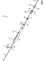
図1は、本発明に係る静脈カテーテル挿入装置20の一実施の形態の分解組立図を示す。図2は、使用準備が完了して未配置状態の静脈カテーテル挿入装置20の組立図を示す。図3は、安全ガイドワイヤが前進した静脈カテーテル挿入装置の想定図を示す。
FIG. 1 shows an exploded view of one embodiment of a venous
静脈カテーテル挿入装置20は、外部筐体1を含む。例示において、外部筐体1は、細長い空洞のシリンダ状である。人間工学に基づくハンドル形状を含む他の形状も可能である。外部筐体1は、医療分野における使用に適した任意の材料を用いて作られてよい。一実施の形態において、外部筐体1は、好ましくは、堅く、透明な医療グレードのプラスチックを用いて成形される。代わりに、外部筐体1は、押出プラスチック管を機械加工してもよい。
The venous
細長いスロット14が、外部筐体1の軸とほぼ並行に、外部筐体1にある。スロット14は、ドエルピン10に適合するか、又は、外部筐体1の内部に沿ってスライダを移動させるために、スライダ4に接続点を提供するような大きさである。スロット14の末端部は、図2及び3に見られるように、三角切欠き部15に広がる。他の形状の切欠き部15でもよい。
An
フロントプラグ2は、外部筐体1の末端部に適合する大きさである。フロントプラグ2は、堅い、透明な医療グレードのプラスチックを用いて、好ましくは成形され、又は代わりに機械加工されてもよい。フロントプラグ2は、接着され、ピン留めされ、溶着され、又はその他によって、外部筐体1の末端部に固定される。フロントプラグ2の末端部は、ルアースリップ接続部16等を含む。ショルダ部又はフランジ17は、外部筐体1の末端部に結合する。フロントプラグ2の基端部は、連結部材18を有し、連結部材18は、持針器6が有し、適合する連結部材19と連結する。図示する例において、連結部材18は、持針器6が有し、対応したらせん状のツメ又は4分の1回転ネジ連結部材19とともに連結する、タブである。連結部材18,19は、他の形状であってもよい。
The
図1〜3の例示する実施の形態において、スロット14及び三角切欠き部15の形状は、回転連結部材18,19との協働で操作するように選択される。スロット14によって、アクチュエータ・ハンドル9は、安全ガイドワイヤ11を末端側へ前進させることができるように外部筐体1に相対的に長手方向に移動できる一方で、同時に、横方向の動きを規制して、アクセス針8及び安全ガイドワイヤ11が早く引き込まれることを回避する。三角切欠き部15に末端部でスロット14を広げることによって、アクチュエータ・ハンドル9は、横方向に選択的に回転し、それによって、安全ガイドワイヤ11が完全に前進した後にアクセス針8及び安全ガイドワイヤ11を引き込むまで、回転連結部材18,19を離して、付勢部材12を解放する。異なる形状又は異なる解放機構が、回転連結部材18,19の所定場所に使用される場合、スロット14及び三角切欠き部15の形状は、解放機構を適合させるように修正される必要がある。
In the illustrated embodiment of FIGS. 1-3, the shape of the
持針器6は、外部筐体1の中に適合する形状及び寸法である。図1〜3に示す実施の形態において、持針器6は、円柱状の外部筐体1の中にスライド移動可能に適合する寸法の円柱形状を有する。他の形状でもよく、概ね、持針器6は、外部筐体1の内部形状に適合する形状である。持針器6は、医療環境における使用に適した材料を用いて、好ましくは成形され、又は代わりに機械加工される。一実施の形態において、持針器6は、堅く、医療グレードのプラスチックを用いて形成される。鋭い勾配が付いた末端部を有する管状アクセス針8は、持針器突出部5に取り付けられ、それによって、順に、持針器6に取り付けられる。アクセス針8は、好ましくは、ステンレス鋼皮下注射管を用いて作られる。小腔又は血液逆流チャンバは、アクセス針8のルーメンに連通し、持針器突出部5と持針器6との間の持針器6の中に位置付けられる。上述のように、持針器6の末端部は、フロントプラグ2の基端部で適合連結部材18と嵌合するように設けられる連結部材19を有する。一実施の形態において、連結部材18,19は、フロントプラグ2に相対的に持針器6が回転することによって、固定及び解除するように設けられる。連結部材18,19は、ビヨネット式接続具を用いて、固定及び解除をしてもよい。図示するように、連結部材は、フロントプラグ2の対応するタブ連結部材18に嵌合する、らせん状の歯止め連結部材19である。一実施の形態において、連結部材は、持針器6の一回転よりも少ないものを用いて、固定及び/又は解除する。他の実施の形態において、連結部材は、持針器6の半回転よりも小さいものを用いて、固定及び/又は解除する。更に他の代替の形態において、連結部材は、持針器6の4分の1回転よりも小さいものを用いて、固定及び/又は解除する。連結部材は、他の形状であってもよい。
The needle holder 6 has a shape and a size that fit into the
付勢部材12は、持針器6とフロントプラグ2との間で適合するように形成され、それによって、それらの分離を促す。持針器6とフロントプラグ2とが互いに固定している場合、付勢部材12の力は、連結部材18,19によって抑えられる。一実施の形態において、付勢部材12はバネである。図1において、付勢部材又は圧縮バネ12は、圧縮状態で示されており、未配置状態の組立静脈カテーテル挿入装置20におけるものである。
The biasing
別の実施の形態において、連結部材18,19は、壊れやすい接着を用いて互いに接続された2つの部材、又は壊れやすいリンクを有する1つの部材によって代替される。部材は、アクセス針8及び安全ガイドワイヤ11を引き込むことが必要なときまで付勢部材12を拘束するように設けられ、そのとき、アクチュエータは、接着又はリンクを破壊し、付勢部材12を解放する。この構成によって、装置20は、再製造又は再使用に一層耐えることができるようになる。
In another embodiment, the connecting
アンジオキャス(ANGIOCATH,登録商標)のような管状の静脈カテーテル13は、アクセス針8の周囲に同軸で適合する。好ましくは、静脈カテーテル13は、アクセス針8とテーパ状末端部とに密接に適合し、それによって、静脈の壁を通って挿入される場合のアクセス針8とカテーテル13との間の段差を最小にする。静脈カテーテル13の基端部にルアー接続部27等があり、それは、静脈カテーテル13を所定位置に保持する弱い締まりばめを用いて、フロントプラグ2の末端部のルアースリップ接続部16に適合する。装置の代替形態では、静脈カテーテル13をフロントプラグ2に取り付けるルアー固定等の固定機構を用いる。
A tubular
スライダ4は、概ね円柱状であり、円柱状の外部筐体1の中でスライド可能に適合する寸法である。外部筐体1の内部形状に応じて、スライダ4は、他の形状であってもよい。スライダ4は、適切な医療グレードの材料を用いて、好ましくは成形され、又は代わりに機械加工される。例えば、スライダは、堅い医療グレードのプラスチックを用いて形成されてもよい。ハンドル9又は操作部材は、外部筐体1にスロット14を介して伸長するドエルピン10等の取付部材を用いてスライダ4に取り付けられる。スライダ4は、持針器6の基端側の外部筐体1に適合する。ピン25は、スライダ4の末端側表面から伸び、持針器6の基端部の穴、ステップ、ボス又は同様の接続機構26に可逆的に係合するように設けられる。静脈カテーテルの挿入及び配置手技の適切なステップの間、ピン25は、接続機構26に係合する。静脈カテーテルの挿入及び配置手技の適切なステップの間にピン25が接続機構26に係合する場合、スライダ4の回転が持針器6に伝達され、それによって、連結部材18,19の係合及び/又は解除が容易になる。ピン25及び機構26は、単なる例示である。ピン25は、雌機構に置き換えられてもよく、適合する雌機構は、持針器6の基端面に配置される。更に、接続機構25,26は、細長いスロット及びスライダ4のスライド移動に対して整列し、その結果、スライダ4の末端側への移動によって、接続機構25,26は接続する。装置20が作動する際、適宜、装置20は、スライダ4と持針器6との間の接続が不可逆的に生じるように、形成されてもよい。
The slider 4 has a generally cylindrical shape, and has a dimension that fits in the cylindrical
図3に示すように、安全ガイドワイヤ11は、直接的に又は間接的に、スライダ4に取り付けられ、その結果、それは、スライダ4に取り付けられたハンドル9とともに前進し、また退避する。好ましい実施の形態において、安全ガイドワイヤ11は、非常に柔軟なニッケル−チタン合金(ニチノール)のワイヤを用いて構成される。この種のワイヤは、非常に柔軟であるため、好ましくは、安全ガイドワイヤ11は、その長さ方向の大部分に沿って封入され、それによって、安全ガイドワイヤ11が前進する間、曲がったり、よじれることを防ぐことができる。このため、図示する例は、持針器6の基端部に取り付けられるサポート管7を含む。安全ガイドワイヤ11は、シース管3の内部ルーメンを通って伸び、安全ガイドワイヤ11の基端部は、シース管3の基端部に取り付けられる。シース管3の末端部は、順にスライダに取り付けられ、その結果、間接的に安全ガイドワイヤ11をスライダ4に取り付ける。サポート管7は、シース管3の中にスライド可能に適合し、その結果、スライダ4が末端方向に前進するとき、2つの部分が互いに順に嵌め込む。サポート管7及びシース管3の嵌め込み動作は、安全ガイドワイヤ11の基端部分のために長さ可変の支持部を備え、それによって、安全ガイドワイヤ11が、前進中に曲がったり、又はよじれることを阻止することができる。サポート管7及びシース管3は、好ましくは、ステンレス鋼の皮下注射管を用いて作られるが、適切な医療グレードの材料が用いられてもよい。大きい直径又は堅いガイドワイヤを用いるような、他の実施の形態の場合、嵌り合い支持管は、必要なく、安全ガイドワイヤ11の基端部は、直接的にスライダ4に取り付けられてよい。
As shown in FIG. 3, the
図4A及び4Bは、静脈カテーテル挿入装置20とともに使用するための安全ガイドワイヤ11の詳細図である。安全ガイドワイヤ11は、好ましくは、約0.004〜0.012インチの直径の非常に柔軟なニッケル−チタン合金ワイヤを用いて構成され、最も好ましくは、直径が約0.008インチである。図4Bに示すように、安全ガイドワイヤ11の末端部は、挿入されるべき標的血管の内径より小さい外径を有する密にらせん状に巻かれて予め形成されている。らせん状の先端は、ガイドワイヤの安全バンパとして作用し、標的血管の内部を穿刺したり、損傷することを防ぐことができる。コイル状のガイドワイヤの先端は、壊れやすく又は傷付きやすい血管を保護するために、特に有用である。安全ガイドワイヤ11がアクセス針8に引き込まれ、安全ガイドワイヤ11がアクセス針8から前進して塑性変形する時にらせん形状を完全に回復する時、ニッケル−チタン合金ワイヤの極だった柔軟性によって、らせん状の末端湾曲部は、真っ直ぐになることができる。図示するように、安全ガイドワイヤ11の末端部は、約0.75回転する直径約0.167インチの第1の小径コイルと、約1回転する直径約0.175インチの第2の大径コイルとを有する。第1及び第2のコイルは、好ましくは、互いにほぼ同一平面上にあり、好ましくはガイドワイヤ11の直線基端部分とも同一平面上にある。安全ガイドワイヤ11の他の形状は、複数の平面、単一のコイル、全半径端部、及び/又は、針の直径よりも小さい径で丸められた端部を含む。
4A and 4B are detailed views of the
図5A、図5B及び図5Cは、静脈カテーテル挿入装置20とともに使用するための他の安全ガイドワイヤ11の詳細図である。本実施の形態において、約0.008インチの直径のニッケル−チタン合金ワイヤの末端部分は、研磨、伸長等によって、約0.004インチの直径のテーパ状にされ、それによって、柔軟性を増して、より小径の血管で使用するために直径のより小さいらせん状に形成され得る。ガイドワイヤ先端のらせん状の湾曲は、好ましくは、標的血管の内径より小さい外径を有する。例示において、らせん形状は、約0.75回転で直径約0.034インチの第1の小径コイルと、約1回転で直径0.059インチの第2の大径コイルとを備える。第1及び第2のコイルは、好ましくは互いにほぼ同一平面上にあり、好ましくはガイドワイヤ11の直線状の基端部とほぼ同一平面上にある。
5A, 5B and 5C are detailed views of another
安全ガイドワイヤ11は、他の寸法及び形状であってもよい。
The
図1〜3に示すように、静脈カテーテル挿入装置20を組み立てるために、アクセス針8は、持針器突出部5の基端面と同一平面で接着され、それは、順に持針器6に接着される。サポート管3は、持針器6の末端穴に配置され、血液逆流チャンバの基端面と同一平面で接着される。形成された安全ガイドワイヤ11は、安全ガイドワイヤ11のコイル状部分がアクセス針8の先端面取り部に適合するまで、アクセス針8及びサポート管7のルーメンを通って前進する。シース管3は、スライダ4を通ってスライド移動し、末端面と同一平面で接着する。シース管3及びスライダ4の組み物は、安全ガイドワイヤ11を超えて前進する。安全ガイドワイヤ11がシース管3の基端部と同一平面にある場合、2つは接着する。スプリング12は、持針器突出部5で圧縮され、フロントプラグ2に前進し、フロントプラグ2及び持針器6の連結部材18,19は連結する。この部品の組み物は外部筐体1に配置され、フロントプラグ2が外部筐体1と同一平面になるまで前進し、フロントプラグ2は適切な角度で回転する。フロントプラグ2は、次に、外部筐体1に接着される。ドエルピン10及びハンドル9は、スライダ4とともに圧縮される。ハンドル9は、安全ガイドワイヤ11をアクセス針8に引き込むために、基端側にスライド移動し、それによって、らせん状の末端湾曲部を真っ直ぐにする。静脈カテーテル13は、次に、アクセス針8の周囲に同心で設けられる。適宜、静脈カテーテル13の挿入装置は、針カバーその他の保護パッケージとともに備えられてもよい。組み立てられた静脈カテーテル挿入装置20は、静脈カテーテル13を含んでおり、次に、包装され、ラベルが貼られ、滅菌される。
As shown in FIGS. 1 to 3, in order to assemble the venous
上述の組み物の説明は、静脈カテーテル挿入装置20の実施の形態を製造するためのプロセスの一例を示すために提示されており、それによって、種々の部品の内部関係も理解されるであろう。本記載の改良及び派生は、特定の選択された組み物又は製造技術によるものと思われる。例えば、接着された部品は、単一に統合された破片等を用いて形成されるように、再び設計されてもよい。静脈カテーテル挿入装置20の他の実施の形態を組み合わせるために、製造プロセスが改良され、応用されてもよい。
The above description of the assembly is presented to show an example of a process for manufacturing an embodiment of the venous
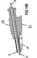
図6は、本発明に係る静脈カテーテル挿入装置20の他の実施の形態の内部図を示す。本実施の形態は、多くの点で、図1〜3の静脈カテーテル挿入装置20に類似する。静脈カテーテル挿入装置20は、外部筐体1と、適宜外部筐体1と一体的に形成されるフロントプラグ2と、持針器6に取り付けられる針8と、安全ガイドワイヤ11と、バネ12と、静脈カテーテル13とを含む。しかしながら、ハンドル9及びスライダ4の機能は、1組の摩擦車22,23を連結するサムホイール21によって代替されてきた。摩擦車22,23は、安全ガイドワイヤ11と接触している。同様に、シース管3及びサポート管7の機能は、ガイドワイヤ・スプール24によって、代替されてきた。これらの機構によって、静脈カテーテル挿入装置20は、よりコンパクトな形状に構成される。安全ガイドワイヤ11は、使用時に、サムホイール21を回転させることによって、前進する。サムホイール21が横方向に移動することによって、持針器6をフロントプラグ2から解除し、それによって、付勢部材12を伸長させ、その結果、針8及び安全ガイドワイヤ11を外部筐体1に収納する。代わりに、針8及び安全ガイドワイヤ11の引き込みを作動させるために、分離ボタン、レバー又はその他の操作部材が備えられてもよい。ガイドワイヤ・スプール24は、安全ガイドワイヤ11を外部筐体1に退避させることを補助するために、適宜、回転バネ又は同様の機構(図示せず)を含む。
FIG. 6 shows an internal view of another embodiment of the venous
一実施の形態において、スプール24でのガイドワイヤ11の長さは、筐体の長さの2倍より長い。他の形態において、スプール24のガイドワイヤの長さは、ガイドワイヤがある血管にアクセスするために、十分である。一実施の形態において、ガイドワイヤ・スプールは、10から60センチの間の長さを有するガイドワイヤを含む。サムホイール21又はホイール22,23を回転させるために必要な力を低減させるために、ガイドワイヤ・スプール24は、クラッチ、カム、又はガイドワイヤ11の前進中にスプール24を解除する他の開放可能な連結部材を含むように設けられてもよい。前進が完了した後、開放可能な連結部材は、次に、スプール24に関連付けられた退避機構を連結する。ガイドワイヤを引き込む必要があると、引き込み機構が作動する。ガイドワイヤ・スプール24を使用することによって、ガイドワイヤ・スプールを含む筐体の長さより非常に長いガイドワイヤ挿入長さを使用することが可能になる。
In one embodiment, the length of the
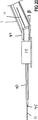
図7〜9は、図1〜3又は図6に記載するような静脈カテーテル挿入装置20を用いた静脈カテーテル挿入方法を示す。静脈カテーテル挿入装置20は、使い捨てであり、使用準備が整った状態で滅菌され医師又は医療施術者に供給される再利用できない装置であって、図2に未配置状態で示す。使用時に、医師は、外部筐体1をハンドルとして使用し、静脈カテーテル挿入装置20を操作する。図7に示すように、未配置状態の装置の場合、アクセス針8は、静脈に穿刺される。静脈血が血液逆流チャンバで観察されると、アクセス針8の末端部は、静脈のルーメンにある。医師は、次に、安全ガイドワイヤ11をアクセス針8から静脈のルーメンへ伸ばすために、末端側へハンドル9を前進させることができる。安全ガイドワイヤ11の末端部分は、静脈の遠い方の壁を偶然に刺すこと等の静脈の損傷を阻止する安全バンパとして作用するように、らせん形状を想定している。安全ガイドワイヤ11が、このように配置される場合、静脈カテーテル13の末端部が静脈のルーメン内に位置するまで、医師は、静脈カテーテル挿入装置20を安全に前進させ続けることができる。一旦、静脈カテーテル13が十分遠くの静脈に挿入されると、医師は、ハンドル9を回転させ、スライダ4を回転させる。それによって、順次、持針器6が回転し、持針器6の連結部材18がフロントプラグ2の適合連結部材19から解除される。(上述の本実施の形態において、ハンドルは、外部筐体1のスロット14の末端部にある三角切欠き部15によって可能になる時計周りに移動する。更に、アクチュエータの機構に関する構造的な特徴は、図1〜3によって詳細に示される。)。ハンドル9が解放される場合、付勢部材23は(本実施の形態では、圧縮バネ12)、持針器6及びスライダ4を基端側の方向へ付勢し、同時に、アクセス針8及び安全ガイドワイヤ11を外部筐体1へ引き込み、静脈カテーテル13のみを静脈のルーメンに残す。図8は、外部筐体1に引き込むアクセス針8及び安全ガイドワイヤ11を示す。三角切欠き部15の形状によって、ハンドル9は、付勢部材12の作用の下で基端側へ移動するため、細長いスロット14に滑らかに移動することができる。最後に、静脈カテーテル13は、図9に示すように、フロントプラグ2の末端部で接続するルアースリップ16から解除され、静脈流源、シリンジその他の装置は、静脈カテーテル13のルアー接続部27に取り付けられる。
7 to 9 show a venous catheter insertion method using the venous
静脈カテーテル挿入装置20は、好ましくは、アクセス針8及び安全ガイドワイヤ11を同時に引き込むが、作動機構は、アクセス針8及び安全ガイドワイヤ11を順に引き込むように改良されてもよい。例えば、作動機構は、まずアクセス針8を引き込み、次に少し遅れて、安全ガイドワイヤ11を引き込む。
Intravenous
代わりに、作動機構は、アクセス針8及び安全ガイドワイヤ11を選択的に引き込むために、1つの作動部材が2つの別個の動き、又は2つの分離した作動部材の選択的な移動を必要とするように改良されてもよい。
Instead, the actuation mechanism requires two actuations of one actuation member or selective movement of two separate actuation members to selectively retract the
静脈カテーテル挿入装置20の代わりの実施の形態において、圧縮バネ12が、作動機構から取り除かれ、それによって、アクセス針8及び安全ガイドワイヤ11をハンドル9を用いて手動で引き込むことが可能になる。静脈カテーテル13が患者の静脈に挿入されると、ハンドル9は、横方向に回転し、持針器6をフロントプラグ2から解除する。次に、ハンドル9は、アクセス針8及び安全ガイドワイヤ11を外部筐体1へ引き込むために、スロット14に沿って基端側に移動する。
In an alternative embodiment of the venous
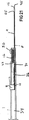
他の実施の形態のカテーテル挿入装置20の部品を図10A及び10Bに示す。図10Aは、内部空間34を有する筐体1を示す。筐体1は、カテーテル挿入装置20の種々の部品を保持するために十分な強度を有する、概ね円柱状の容器を示す。取付機構40は、内部空間34の中に見ることもできる。後続の図に示すように、取付機構40は、ハンドル1に又は内部空間34の中に抑制部材36を固定するために使用されてもよい。アクセス針8は、筐体1の末端部に位置付けられ、内部空間34から出る。アクセス針は、末端部45及びルーメン46を有する。アクセス針8は、内部空間34に相対的にスライド移動可能である。解放バー32は、筐体1の中に針8を保持するために、使用される。本実施の形態において、付勢部材12は、筐体1と針支持部29との間で圧縮される。解放ボタン30は、解放バー32を傾動させるために、使用され、付勢部材12が内部空間内のアクセス針8を基端側へ伸長して移動させることが可能になる。
Parts of a
本明細書において説明されたカテーテル挿入装置は、解放時に、少なくとも針の一部が筐体外部の所定位置から内部空間23の中の所定位置へ挿入針を移動させるように設計して、適用された付勢部材を含む。更に、同じ又は異なる付勢部材が、解放時に、筐体外部の所定位置から筐体1の中の所定位置へガイドワイヤ11を移動させるように、設計して、適用される。本明細書で説明した実施の形態の多くで説明された形態において、針8又はガイドワイヤ11の末端側への移動は、標的血管への挿入を示し、基端側への移動は、標的血管からの引き込みを示す。付勢部材は、考察のために従来のものを用いて説明する。他の移動は、中へ前進させるため、又は中から引き込むために使用されてもよい。付勢部材の移動及び設計に関する説明は、適宜調整されるであろう。一形態において、付勢部材は、拘束状態から解放する際に針8を移動させるように、設計して、適用され、それによって、針8は、完全に内部空間34の中に含まれる。他の形態において、付勢部材は、拘束状態から解放する際にガイドワイヤ11を移動させ、それによって、ガイドワイヤ11の全長さが内部空間34の中に完全に含まれる。図11Aに示す実施の形態において、付勢部材12はバネである。
The catheter insertion device described herein is designed and applied so that at the time of release, at least a part of the needle moves the insertion needle from a predetermined position outside the housing to a predetermined position in the internal space 23. A biasing member. Further, the same or different biasing members are designed and applied to move the
図10Bは、ガイドワイヤ11と関連する部品を示す。図示する実施の形態において、ガイドワイヤ11の基端部は、ガイドワイヤ支持部38に取り付けられる。ガイドワイヤの末端部は、使用時に、アクセス針に沿って伸び、筐体1の末端部を超える。使用前に、ガイドワイヤ11の一端部は、常に、ハンドル1に若しくは内部空間の中に又はその両方に取り付けられる。使用後に、ガイドワイヤ11は、ハンドル1の中に又は内部空間34の中に完全に含まれる。ハンドル9は、直接的に又は間接的に、ガイドワイヤに取り付けられる。ハンドル9は、内部空間34に対してガイドワイヤ11を移動させるために、筐体1に対して移動可能である。
FIG. 10B shows the parts associated with the
ガイドワイヤ支持部38及びガイドワイヤ11は、適切な技術を用いて接続する。ガイドワイヤ11が小径の、柔軟な線材の、コイル状の、壊れやすい、又は本明細書で説明したような、医療技術でよく知られたワイヤであるため、ガイドワイヤ支持部38は、ガイドワイヤ11に対する機械的強さを提供するために使用される。ガイドワイヤ支持部38は、図示した実施の形態と異なる形状を有し、更に、ガイドワイヤ11の一端部を支持するという機能的な要求を満たす。ハンドル9は、直接的に又は間接的に、ガイドワイヤ11に取り付けられ、その結果、ハンドル9の移動によって、ガイドワイヤ11が内部空間34又は筐体1に相対的に移動する。図示する実施の形態において、ハンドル9は、ガイドワイヤ支持部38を用いてガイドワイヤ11に取り付けられる。図10Bは、抑制部材36をも示す。抑制部材36は、ガイドワイヤ11の移動を阻止するために使用される。一形態において、ハンドル9に取り付けられた抑制部材36は、アクセス針8に関するガイドワイヤ11の動きを制限する。図示する実施の形態において、抑制部材36の一端部は、ガイドワイヤ支持部38に取り付けられる。抑制部材36の他端又は他の部分は、ハンドル1に取り付けられる。一実施の形態において、抑制部材は、ガイドワイヤ支持部38又はハンドル9と、ハンドル1又は内部空間34との間で伸びる。抑制部材36は、取付機構40に、適切な手段によってハンドル1に、又は内部空間34の中に取り付けられてもよい。
The
図10C及び10Dは、カテーテルハブの実施の形態の側面図を示す。図10Dは、従来のカテーテルハブ・アセンブリ13である。図10Cは、傾斜した基部61を有するカテーテルハブ13Aであり、それによって、図19A及び19Bを参照して更に説明するように、カテーテルを血管に容易に挿入することが可能になる。
10C and 10D show side views of an embodiment of a catheter hub. FIG. 10D shows a conventional
図10E及び10Fは、血管への穿刺に関する早期表示を可能にするための、アクセス針8における種々の装置43を示す。図10Eは、単一表示開口部43であり、図11Fは、2つの表示部43の実施の形態を示す。表示部43は、血液が針ルーメン46の中に存在することの表示を提供するために、適切な大きさ及び形状を有する。図示する形状は、図10Eの長方形であり、また図10Fの卵形である。円形状が使用されてもよい。
FIGS. 10E and 10F show
図10Gは、針6と、ガイドワイヤ11と、カテーテルハブ13に取り付けられたハンドル1の末端部との平面図を示す。針8の長さは、図示するようにカテーテルの末端部を超えて伸びるように選択される。針末端部45は、カテーテル端部を超えて、血管を穿刺できるだけ十分遠くに伸びる。ガイドワイヤ11は、アクセス針8によって支持され、アクセス針8に相対的に移動可能である。ガイドワイヤ11は、針末端部45から伸びた状態で示される。
FIG. 10G shows a plan view of the needle 6, the
ガイドワイヤ11は、図示する形態において、紙面においてコイル状である。ガイドワイヤコイルは、針ルーメン46に形成され、コイル状で針8から前進してもよく、又はガイドワイヤ11は、アクセス針ルーメン46の中で直線形状に拘束されてもよい。一旦、アクセス針ルーメン46から伸びると、ガイドワイヤ11は、予め定められたコイル状の形状と想定される。他の形態において、ガイドワイヤ11は、コイル状ではなく、代わりに使用中に直線状のままである。種々のコイルタイプが、図1,4A,4B,5B,5A,16A〜17B,22,23及び24に示され、また説明される。
In the illustrated form, the
アクセス針8は、アクセス針8がカテーテル13の中に位置付けられる場合に、カテーテル13の末端部の可視的な血液逆流表示部42を含む。図示する実施の形態において血液逆流表示部43は、針8の末端部の側壁に開口部43を含む。血液逆流ポート42は、カテーテル・アセンブリ13を介して可視化し、それによって、血管への穿刺とほぼ同時の表示が可能になる。血液逆流表示部42は、アクセス針8の筐体1を超えて伸びる部分の中にある。図示するように、血液逆流表示部42は、針8に形成され、筐体1の末端部より末端側の針の部分に形成される開口部43である。
図10Gは、ガイドワイヤと血液逆流開口部との関係をも示す。ガイドワイヤを操作する際に配慮する事項の1つは、ハンドル9の不注意な動作である。ハンドル9が基端側へ移動する場合、例えば、ガイドワイヤの先端部は、針ルーメン46から逆流チャネル43を通じて飛び出す。この例において、ガイドワイヤ11は、アクセス針ルーメン46に再び通される必要がある。図11A及び11Bは、このような望ましくない基端側への移動を、抑制部材36を用いて阻止するための一技術を示す。抑制部材36は、ガイドワイヤ11の移動を規制するために使用される。図11Aによく示されるように、抑制部材36は、ハンドル9に取り付けられ、アクセス針8に相対的なガイドワイヤ11の基端側への動きを制限する。抑制部材36は、強く引かれ、ハンドル9が基端側へ更に移動することを規制する。図示するように、解放ボタン30の作動前に最も基端側に位置する場合、ガイドワイヤ11は、アクセス針8の中に留まる。一実施の形態において、抑制部材36は、内部空間36の中に適合するように裁断されたケブラー繊維の細長い一片である。抑制部材36は、ガイドワイヤの移動を制限し、又は禁止する幅広い種々の材料のいずれかでよい。抑制部材36は、ハンドルが移動するにつれて抵抗を増すような柔軟な部材であってもよく、それによって、ユーザは、その方向へ更に移動させることが望ましくないという触感フィードバックを感じることができる。
FIG. 10G also shows the relationship between the guidewire and the blood reflux opening. One of the considerations when operating the guide wire is the careless movement of the
上述の図7〜9と同様に、図11A〜14Bは、例示のカテーテル挿入手順を説明するために使用される。カテーテル13の挿入、及びカテーテル挿入装置20の実施の形態の操作は、筐体1の内部の断面図を含む一連の図を用いて説明され、例示する装置は、血管にアクセスするために使用される。
Similar to FIGS. 7-9 described above, FIGS. 11A-14B are used to illustrate an exemplary catheter insertion procedure. The insertion of the
図11Aは、血管を刺すための針を使用する際の準備位置にある筐体1を示す。ハンドル9の基端側への移動が、抑制装置35によって制限され、その結果、ガイドワイヤ11が、内部空間34及び針ルーメン46の中の所定位置に留まっていることに注意すべきである。図11Bは、血管が付着する前に、カテーテル13の中に挿入される装置20を示す。図11Cは、血管壁(VW)を介して血管内に刺さる針8を示す。血液(B)は、血液逆流表示部42に現れる。血液逆流表示部42によって、血管への穿刺を早期に表示することが可能になる。ガイドワイヤ11は、針45の末端部と血液逆流開口部43との間のアクセス針ルーメン46の中に留まる。
FIG. 11A shows the
図12Aは、ガイドワイヤが前進した後の内部部品の位置を示す。図示するように、ハンドル9は、筐体1に相対的に末端側へ移動する。この移動により、ガイドワイヤ11は、針末端部45を超えて前進し、抑制部材36の張力を低減する。図12Bは、針8から出た後のコイル状を想定したガイドワイヤ11を示す。ハンドル9が続けて移動することによって、ガイドワイヤ11は、更なる血管(V)に前進する。
FIG. 12A shows the position of the internal parts after the guidewire has been advanced. As shown in the figure, the
図13Aは、針末端部45を超えて、ガイドワイヤ11に沿って前進するカテーテル13を示す。カテーテルが血管Vに挿入されると、ガイドワイヤ11及びアクセス針8を引き込むことができる。ガイドワイヤ11及び針8を引き込むには、種々の方法がある。引き込みは、同時又は順次になされてよい。順次の場合、ガイドワイヤ又針のいずれかが、最初に引き込まれる。引き込むことは、ガイドワイヤ11、針8、又はガイドワイヤ11及び針8の両方に、直接的に又は間接的に取り付けられたノブ、ハンドル、スライダその他部品の手動操作によって行われる。引き込むことは、ガイドワイヤ11及び針8の1つ又は両方を引き込むように設けられた自動機構を使用することによっても行われる。要素を自動的に引き込むことは、要素を手動で引き込むことと組み合わされてもよい。引き込む技術又は実行される手順に関わらず、完全に引き込む手順は、筐体末端部1の基端側の、及び/又は内部空間34の中の、針及びガイドワイヤの両方で終了する。一形態において、引き込み操作の結果、ガイドワイヤ11及び針8は、完全に内部空間38の中にあり、その結果、鋭く、血に晒された部品は、筐体1の中に収容される(例えば、図14A、15 13C,18G及び31参照)。
FIG. 13A shows the
自動的に引き込む手順が、図12Aから始まって記載される。解放ボタン30が押下されると、解放バー32が、針支持部29の基端部から解除される。付勢部材12は、基端側の方向に拘束され、その方向へ伸長する。付勢部材12が基端側へ移動すると、それによって、針支持部29も基端側へ、針8に沿って移動する。針支持部29が基端側へ移動することによって、ガイドワイヤ支持部38及びハンドル9も、ガイドワイヤ11に沿って基端側に移動する。図13Bは、図13Aに示すように血管を更に下るのではなく、カテーテル13の末端部の近くで示されるガイドワイヤ11が基端側へ移動する様子を示す。図13Cは、矢印によって示される、連続的な基端側への移動を示す。ここで、ガイドワイヤ11及び針8の両方が、カテーテル13から引き込まれて、筐体1の末端部より基端側にある。図13Dは、引き込む手順の最後の筐体1の断面図である。引き込む手順の最後に、カテーテル13は血管vに挿入されるが、筐体1は図示するようにカテーテル13に、まだ取り付けられている。針8及びガイドワイヤ11は、筐体末端部1より基端側と内部空間34の中との両方にある。更に、図13Dは、筐体1及び内部空間34の中に、完全にガイドワイヤ11及び針8の両方を示す。
The automatic retraction procedure is described starting from FIG. 12A. When the
図14Aは、カテーテル・アセンブリ13から分離された筐体1を示す。この時、筐体1は、廃棄準備ができており、カテーテル13は、図14Bに示す血管の中にある。図14A及び15に示すように、針末端部45は、筐体末端部35から距離dで引き込まれる。針8及びガイドワイヤ11は、完全に筐体内部34にある。距離dは、筐体の長さ、針の長さ、付勢部材に蓄えられられたエネルギーの大きさ、及び引き込むために必要な移動長さのような多くの設計要素に基づいて調整されてもよい。距離dは、1mmから約20mmであり、図18Gに示すように、筐体末端部35より基端側である。
FIG. 14A shows the
図14Aを参照して、針8及びガイドワイヤ11が筐体11に引き込まれると、血液に晒された鋭い、装置20の部品は、典型的には、針8及びガイドワイヤ11であって、ハンドル内部空間34の中にある。この追加的な機構によって、安全性を更に増すことができ、針及びガイドワイヤが筐体内又は内部空間の中に確実に留まる。本発明の一形態において、抑制部材は、内部空間34の中に位置付けられ、それによって、アクセス針8又はガイドワイヤ11の1つ又は両方が移動することを制限する。抑制装置は、引き込む手順の間に必要な移動長さに基づいて、内部空間の中に位置付けられる。抑制部材は、ある実施の形態では、針及び/又はガイドワイヤが移動する端部近傍の内部空間36の中に位置付けられる。針及びガイドワイヤの移動端部は、応用に応じて変化してもよい。適切に位置付けられると、ガイドワイヤ11、針8又はガイドワイヤ若しくは針に係合した部品が末端側に移動することが規制され、その結果、ガイドワイヤ及び針のいずれもが筐体末端部1から伸長する。代わりに、適切に位置付けられると、ガイドワイヤ11、針8又はガイドワイヤ若しくは針に係合した部品が末端側に移動することが規制され、その結果、ガイドワイヤ及び針は、内部空間34の中に留まる。内部空間34は、筐体1の中のキャビティであってもよく、又は筐体1の中の空洞(hollow space)であってもよい。
Referring to FIG. 14A, when the
一実施の形態において、抑制装置は、基端側及び末端側の両方への移動を規制する。他の実施の形態において、抑制装置は、基端側への移動を許容するが、基端側への移動を規制する。図15は、内部空間34の中の抑制装置64の一実施の形態を示す。抑制装置64は、筐体末端部1に向かって解放した基部を有する面取りされたコーン形状を有する。抑制装置は、柔軟な材料を用いて作られ、ガイドワイヤ11、針8及び関連付けられたサブ・部品が基端側へ一方向に移動できるだけの十分なアクセスを可能にする。図示する実施の形態において、抑制装置は、針支持部29の基端部で固着するように、設計して適用される。抑制装置29は、ガイドワイヤ及び針を望ましい位置に留めるために、あらゆる部品を保持し、制限し、又は規制して連結するように、設けられてもよい。抑制装置64は、筐体内壁部とガイドワイヤ及び/又は針部品との間の摩擦適合を生み出す内部空間34の中で狭まっていってもよい。更に、ガイドワイヤ及び針部品は、針又はガイドワイヤのいずれかの基端側への初動時に連結し、固定するように、設けられてもよい。一実施の形態において、基端側への移動によって、ガイドワイヤ及び針がともに固定され、その結果、それらは、単一のユニットとして筐体1の中を基端側へ移動してもよい。抑制装置64は、次に、ガイドワイヤ若しくは針の1つ、又は単一のガイドワイヤ/針ユニットの機構と連結するように、設計して、適用されてもよい。
In one embodiment, the restraining device regulates movement to both the proximal side and the distal side. In another embodiment, the suppression device allows movement to the proximal end side but restricts movement to the proximal end side. FIG. 15 shows an embodiment of the
他の実施の形態において、抑制装置64は、内部空間34の基端部に向かう角度ファイを1つ以上含む。実質的には、針/ガイドワイヤの一方向(ここから基端部へ)の通過が可能であり、反対方向(ここから末端部へ)の移動を阻止すれば、どのような形状であっても使用され得る。図では、針ガイドの移動を制限するように示すが、これは単に説明のためである。抑制装置は、係合によって筐体内部に引き込むことができ、また筐体内部からの前進を阻止できる範囲で、針又はガイドワイヤ組み物のあらゆる部品の中で連結するように設計して、適用される。他の抑制機構及び形態は、例えば、1つ以上のリング、くさび又は他の摩擦固定設計を含む。
In other embodiments, the restraining
ガイドワイヤ11は、図3,4a,4b,5a〜5c,8,22,23及び24に示して説明した湾曲状、コイル状若しくは直線状、又は医学的応用のためのガイドワイヤの分野で従来からある他の形状を含む多数の異なる設計のいずれかであってもよい。図16A〜17Bの実施の形態の図において、ガイドワイヤ11は、アクセス針ルーメン46の中でコイル状である。図16A〜17Bは、カテーテル挿入装置20に使用されるアクセス針8の実施の形態の末端部分の端面図(図16A及び17A)及びアイソメトリック図(図16B及び17B)である。図示するアクセス針8a及び8bは、末端部45、及び末端部から基端部まで伸びるルーメン46を形成する内壁部を有する。アクセス針8を参照して説明したように、アクセス針8a及び8bは、内部空間46に関してスライド移動可能であり、筐体末端部1を超えて伸びる。アクセス針側壁8a,8bの開口部43は、アクセス針ルーメン46と連通する。アクセス針側壁の開口部43は、アクセス針末端部45より基端側に位置する。ガイドワイヤ11は、アクセス針によって支持される。
The
アクセス針8a,8bのルーメンは、アクセス針ルーメン46に相対的なガイドワイヤ11の方向性を維持する断面形状を有する。アクセス針8a,8bは、非円形の断面形状を有するアクセス針ルーメンを示す。一形態において、アクセス針ルーメンの形状は、ガイドワイヤの方向性を維持するために使用され、それによって、ガイドワイヤがアクセス針から血液逆流表示部又は開口部43を介して排出されてしまうことを阻止する。図16A〜17Bの形態において、ガイドワイヤ11が基端側へ血液逆流開口部43の領域に引き込まれる場合、機構(図16A及び16B)又は針の内部形状(図17A及び17B)のいずれかによって、ガイドワイヤ11は、アクセス針ルーメン46から開口部43を介して排出することを阻止する方向で維持される。図16A〜17Bに示す機構を維持する方向性は、単独で又は互いの組合せで、使用されてもよい。他の変形例において、機構を維持する方向性は、図10B及び11Aを参照して説明した抑制装置36の代わりに又はそれと組み合わせて、使用されてもよい。
The lumens of the access needles 8 a and 8 b have a cross-sectional shape that maintains the directionality of the
ある実施の形態において、アクセス針側壁の中に形成された機構は、アクセス針ルーメン46に相対的なガイドワイヤ11の方向性を維持する。機構は、側壁又は側壁に接続された分離部品に形成されてもよい。図16A及び16Bは、アクセス針ルーメンに相対的なガイドワイヤ11の方向性を維持するために、アクセス針側壁の中に形成された機構52を示す。図示する実施の形態において、機構52は、側壁に沿って形成される溝である。溝の深さは、ガイドワイヤ11を制限し、針ルーメン46の中の方向性を維持するために十分である。
In certain embodiments, a mechanism formed in the access needle sidewall maintains the orientation of the
図17A及び17Bに示す実施の形態において、アクセス針ルーメン46の断面形状は、ガイドワイヤ11が血液逆流開口部を介してルーメン46をから抜け出ることを阻止するために、針ルーメン46の中のガイドワイヤを制限するために使用される。図17A,17Bは、楕円形の断面形状を有するアクセス針ルーメン46を示す。他の断面形状が、アクセス針ルーメン46の中にガイドワイヤ11を制限するために使用されてもよい。
In the embodiment shown in FIGS. 17A and 17B, the cross-sectional shape of the
一実施の形態において、アクセス針ルーメン46は、アクセス針ルーメン46の中で少なくとも半回転を形成するように、コイル状のガイドワイヤ11を制限する。代わりの実施の形態において、アクセス針ルーメンは、アクセス針ルーメン46の中で1つ以上の回転を形成するように、コイル状のガイドワイヤ11を制限する。
In one embodiment, the
血管アクセス装置を支援するガイドワイヤの使用に関する他の課題は、穿刺中又はその前にガイドワイヤが末端側へ早急に前進することである。図18A〜18Hは、メインチャネル14及びガイドチャネル70を有するカテーテル挿入装置20の実施の形態を示す。筐体1の中にメインチャネル14は、筐体1に沿ってハンドル9の移動を制限する。ガイドチャネル70は、メインチャネル14に隣接し、メインチャネル14からアクセス可能である。ガイドチャネル70は、ハンドル9がガイドチャネル70の中にある場合に、ハンドル9の移動を阻止又は規制するように設けられる。
Another challenge with the use of guidewires to assist vascular access devices is that the guidewire is advanced rapidly distally during or before puncture. 18A-18H show an embodiment of a
図示する挿入装置は、図7〜9及び図11A〜14Bを参照して上述した手順と同様の挿入手順によって使用される。図18A〜18Hのカテーテル装置20の部品及び操作は、上述の実施の形態と同様であり、同一の要素には同一の参照符号が使用される。ガイドチャネルは、ガイドワイヤ11の末端側への移動を規制又は阻止するための追加的な機構の一例である。筐体1は、メインチャネル14に加えて、ガイドチャネル70を有する。ガイドチャネル70は、図18Bのアイソメトリック図に最もよく示される。
The insertion device shown is used by an insertion procedure similar to that described above with reference to FIGS. 7-9 and 11A-14B. The parts and operation of the
図18A及び18Bは、それぞれ、メインチャネル14の基端側の所定位置にハンドル9を有するカテーテル挿入装置20の一実施の形態の側面図及びアイソメトリック図を示す。カテーテル挿入装置20の本実施の形態は、内部空間34を有する筐体1を含む。アクセス針8は、内部空間34に関してスライド移動可能であり、筐体末端部1から伸びる。ガイドワイヤ11は、アクセス針8によって支持され、アクセス針8に相対的に移動可能である。ハンドル9は、ガイドワイヤに取り付けられる。ハンドルの移動が制限され、その結果、ガイドワイヤ11の少なくとも一部が、内部空間34に常に留まる。図示する実施の形態において、ハンドル9は、ガイドワイヤ支持部38を用いてガイドワイヤ11に取り付けられる。ハンドル9及びガイドワイヤ支持部38は一体の部品であってもよい。手順の最初(図18A)と手順の最後(図18G)に示されるように、ハンドル9の移動が制限され、その結果、ガイドワイヤの基端部分11Aは、内部空間34に常に留まる。
18A and 18B show a side view and an isometric view, respectively, of one embodiment of a
図18Aに示すように、ハンドル9の基端側への移動は、抑制装置36によって規制され又は止められる。図18Bに示すように、ハンドル9及びガイドワイヤ11が基端側へ引き込まれる場合であっても、ガイドワイヤ11は、開口部43よりも末端側かつ末端部45より基端側の針ルーメン46の中に留まる。図18A〜18Dに示す実施の形態において、抑制部材36によって、基端側へのガイドワイヤの移動が阻止され、保持チャネル70によって、使用時に、末端側へのガイドワイヤの移動が阻止される。ガイドワイヤ11の一端部は、取付ポイント40を用いて筐体1に固定される。図18A及び18Bに示すように、ガイドワイヤ11は、アクセス針8の中に配置される。
As shown in FIG. 18A, the movement of the
ガイドチャネル70は、摩擦又は干渉適合部を含んでもよく、又は、一旦ハンドル9がガイドチャネルに移動すると、ハンドル9を規制する。例えば、ガイドチャネルは、ハンドルをチャネル70の中に開放可能に固定するために、チャネル70の末端部に固定部、タブ等の機構を均一な幅で備える。代わりに、ガイドチャネル70に相対的なハンドルの移動は、ハンドル9を固定しかつガイドチャネル70から固定解除するために使用されてもよい。例えば、ハンドル9は、固定するために、J形状のガイドチャネルに移動し、チャネル14から戻るために、J形状のガイドチャネルから移動してもよい。他の代替の形態において、ガイドチャネル70の幅は、末端側に進んだハンドル9に摩擦を生じさせるために、末端側ほど小さい。
The
図18C及び18Dは、ガイドチャネル70の中の末端側へ前進したハンドル9を示す。図18A及び18Bを比べると、ハンドル9が末端側へ移動することによって、ガイドワイヤ11の末端側への対応する移動が生じる。図18Dに示すように、ガイドワイヤ11は、なお、アクセス針8の中にあり、かる末端部45より基端側にある。ガイドチャネル70は、ハンドル9がチャネル70の中に移動する場合、ガイドワイヤ11が針8の中に留まるように設計される。針が開口部43を含むそれらの実施の形態の場合、チャネル70は、開口部43と針45の末端部との間のガイドワイヤ11の移動を制限する。
18C and 18D show the
図18E及び18Fは、図8,12A及び13を参照して説明したようなガイドワイヤの前進を示す。図18E及び18Fは、カテーテル挿入装置の実施の形態をも示す。そのカテーテル挿入装置は、ガイドワイヤ11がアクセス針末端部45を超えて伸びる場合に、ガイドワイヤ11の一端が内部空間34の中に拘束される。
18E and 18F show the advancement of the guide wire as described with reference to FIGS. 8, 12A and 13. FIG. 18E and 18F also show an embodiment of the catheter insertion device. In the catheter insertion device, when the
図18G及び18Hは、図9,13A,13B,13C,13D,14及び15を参照して説明した引き込み手順の最後での部品の配置を示す。図18Gは、筐体末端部35のちょうど基端側の所定位置までの、針末端部45の引き込みを示す。この最終位置は、図14A及び15を比べて、針末端部45が筐体末端部35から距離dだけ引き込まれた位置である。本形態において使用される部品の空間的な関係は、針末端部が距離dだけ引き込まれるように、変形されてもよい。本明細書で説明した実施の形態の各々において、ガイドワイヤは、同じ位置又は針末端部45の基端側まで、すなわち、少なくとも筐体末端部35より少なくとも基端側まで又は上述のように距離dだけ、引き込まれる。
18G and 18H show the component placement at the end of the pull-in procedure described with reference to FIGS. 9, 13A, 13B, 13C, 13D, 14 and 15. FIG. 18G shows the retraction of the needle
図18A〜18Dは、抑制装置36及びガイドワイヤチャネル70によって提供されるハンドル9の移動の規制を示す。カテーテル挿入装置20は、図18C及び18Dに示す「使用準備完了」の状態で使用者に提供されてもよい。この形態の場合、不注意で末端側にガイドワイヤ11が前進することが、ガイドチャネル70のハンドル9の配置によって減少する。ガイドワイヤ11を末端側に、又は針末端部45を超えて前進させるために、ハンドル9及びガイドワイヤ11は、ハンドル9をガイドチャネル70から自由にする必要があるとき、基端側に移動する。この基端側への移動は、針8におけるガイドワイヤ11を維持するために、図18Aに示すように抑制装置36によって制限される。従って、ハンドル9及びガイドワイヤ11は、針/ガイドワイヤ引き込み手順に従ったカテーテル挿入によって、本明細書で記載したように末端側に前進する。
18A-18D show the restriction of the movement of the
血管穿刺又は一般的な進入に関わる他の課題は、挿入後に患者が快適であるために、カテーテルの方向性を備えることである。方向性に関する1つの潜在的な問題は、図14Bに最もよく示される。図4Bは、従来のカテーテルハブ・アセンブリ13を示しており、カテーテルルーメンは、平坦なベースと概ね碁盤目配列のハブに適合するために、下方へ曲がる。その一方、図19A及び19Bは、傾斜カテーテルルーメンを示す。カテーテルルーメン角θは、血管Vに進入する針8の接近角を可視化するように、選択される。図19Aに示すように、筐体1は、カテーテルルーメンに整列される。結果として、針8は、カテーテルルーメン角θにも整列する。図19は、カテーテルハブ13Aの断面図であり、ベース61とカテーテルルーメンとの間に形成されるカテーテルルーメン角θを示す。一実施の形態において、カテーテルルーメン角θは、約0度から約90度までで変動する。他の実施の形態において、カテーテルルーメン角θは、約0度から約25度より小さい角度で変動する。カテーテル13Aは、図7及び11Cに示すカテーテルハブ13とはことなる使用がなされる。図7及び11Cに示すように、筐体及びカテーテルは、カテーテルベースが肌に接触しない血管の上方で支持されていない。これに対して、カテーテル13Aが使用される場合、ベース61は、肌に接触しており、肌に適切に配置される場合、カテーテルルーメン角θは、針末端部45を案、肌を介して血管Vの中に案内するために使用されてもよい。傾斜カテーテルハブによって、患者の快適さが向上し、カテーテルが不注意で外れてしまう可能性が低減する。このような利点は、ハブ及びルーメンによってもたらされるものであり、ハブ及びルーメンは、カテーテルルーメンが血管への挿入のために傾斜しているので、肌によりよく接触するであろう。
Another challenge associated with vascular puncture or general entry is to provide catheter orientation for patient comfort after insertion. One potential problem with directionality is best shown in FIG. 14B. FIG. 4B shows a conventional
図20は、内部空間34及び長軸を備えた筐体1を有するカテーテル挿入装置の実施の形態を示す。機構80は、筐体末端部35に位置付けられ、又は筐体末端部35から形成される。機構80がカテーテル13に係合する場合、筐体長軸は、カテーテル13の長軸からオフセットする。オフセットは、筐体オフセット角βによって示される。図示するように、筐体オフセット角βは、約10度から約15度である。他の実施の形態において、筐体オフセット角βは、約5度から約50度より小さい範囲である。アクセス針8は、機構80を通過し、持針器又は他の筐体内の部品に取り付けられる。針及び/又は持針器は、内部空間34に関してスライド移動可能であり、アクセス針8は、機構80に関してスライド移動可能である。一実施の形態において、機構80がカテーテル13に係合する場合、筐体長軸は、カテーテルの長軸からオフセットし、それによって、180度より小さい筐体オフセット角βを形成する。他の形態において、機構80がカテーテル13に係合する場合、筐体長軸は、カテーテルの長軸からオフセットし、それによって、60度より小さい筐体オフセット角βを形成する。他の形態において、機構80がカテーテル13に係合する場合、筐体長軸は、カテーテルの長軸からオフセットし、それによって、45度より小さい筐体オフセット角βを形成する。オフセット角βの結果として、引き込む手順において、針及びガイドワイヤは、最初は筐体の長軸に対して所定角度で、オフセット角βに従って移動する。機構80を通過した後に、引き込み移動は、平行な移動に変わり、ある実施の形態においては筐体1の長軸と同一方向の移動に変わる。そのように、ガイドワイヤ及び/又は針が機構80を通して引き込まれると、アクセス針及びガイドワイヤは、筐体1の長軸に実質的に平行な内部空間34に引き込まれる。
FIG. 20 shows an embodiment of a catheter insertion device having a
血管への進入角を調整し、カテーテル挿入装置の使用を容易にする他の技術は、針が筐体から出る箇所を変更することを含む。針を移動させることによって、前の実施の形態において図示したような、また従来の一般的な安全なシリンジのような筐体の中央部分から退出すると考えられ、異なるアクセス角度が筐体1と標的血管との間で形成される。
Other techniques for adjusting the angle of entry into the blood vessel and facilitating use of the catheter insertion device include changing the location where the needle exits the housing. By moving the needle, it is assumed that the central access point of the housing as shown in the previous embodiment and as in the conventional general safe syringe is retracted, and the different access angles are different from the
図21は、内部空間34及び長軸を備えた筐体1を有するカテーテル挿入装置の一実施の形態を示す。内部空間34は、カテーテルの挿入が完了した後にガイドワイヤ11及びアクセス針8の全てを含むような寸法で設計される。アクセス針8は、内部空間34に関してスライド移動可能である。針の軸は、筐体長軸からオフセットする。オフセット針は、筐体の1つの壁部の近くにあり、中央ではない筐体末端部から退出する。ここで、針の退出は、筐体長軸の下方で平行に伸びる。
FIG. 21 shows an embodiment of a catheter insertion device having a
付勢部材12は、筐体軸と同方向である。解放バー32は、筐体の1つの壁部に向けて位置付けられた端支持部21を連結するように設けられる。部品は、上述のように、針及びガイドワイヤの挿入及び引き込みに作用する。
The biasing
図示する実施の形態において、筐体の長軸は、府西部座12の軸を通って伸びる。ガイドワイヤ11は、針8と同方向である。針軸は、平行であるが、筐体長軸にはオフセットしない。付勢部材12は、針及び付勢部材が同方向であった前の実施の形態とは対照的に、針8の上方にある。ここで、針及びガイドワイヤは、筐体の1つの壁部に近づくように移動してもよい。結果として、針は、1つの壁部に近い筐体から出て、その結果、針が筐体のほぼ中央から退出する前の実施の形態形態よりも、筐体を肌の近くに保持することが可能になる。他の形態において、抑制部材36及び取付箇所40は、針が筐体の1つの壁部へ異動することを支援するように、針の上方へ移動してもよい。
In the illustrated embodiment, the long axis of the housing extends through the axis of the Fus
例えば、図1,3,4A,4B,5A,5B,5C,8,10B,10G及び16A〜17Bに図示して説明するように、種々のガイドワイヤの設計領域は、変更されてよい。更に、ガイドワイヤの設計は、本明細書で説明したカテーテル挿入装置にも使用される。本明細書で図示して説明したように、ガイドワイヤ11は、コイル状、非コイル状又は湾曲した形状で使用されてもよい。更に、第2部分の末端部は、1つ以上の全半径末端部と、ガイドワイヤと同じ材料の半球部と、ガイドワイヤ又は第1の直径とほぼ同様の直径を有する末端部と異なる材料の半球部とを備える。
For example, as illustrated and described in FIGS. 1, 3, 4A, 4B, 5A, 5B, 5C, 8, 10B, 10G, and 16A-17B, the design area of the various guidewires may be varied. Furthermore, the guidewire design is also used in the catheter insertion device described herein. As illustrated and described herein, the
図22は、第1直径を有する第1部分と、縮小部分84と、第1直径より小さい第2直径を有する第2部分とを備えたガイドワイヤ11の断面図である。ガイドワイヤ末端部85は、丸められた先端部87又はボール状先端部87に形成され、末端部85に取り付けられる。第1直径及び第2直径は、アクセス針8の内径より小さい。一実施の形態において、第1直径は、0.008インチの直径のワイヤを用いて作られ、第2直径は、全半径末端部85を備えた0.004インチの直径のワイヤを用いて作られる。遷移部又はテーパ部84は、図示するように、第1直径から第2直径への直線的な変化である。一実施の形態において、先端部87は、末端部85とともに又は末端部85に取り付けられた別部品とともに形成された、0.005及び0.012インチの間の直径を有する半球部である。半球部87は、各種金属、合金、プラスチック、ニチノールその他体内での使用に適した材料を用いて形成されてよい。
FIG. 22 is a cross-sectional view of the
図23は、第1直径を有する第1部分と、縮小部分84と、第1直径より小さい第2直径を有する第2部分とを備えたガイドワイヤの断面図である。ガイドワイヤ末端部85は、丸められた端部に形成される。第1直径及び第2直径は、アクセス針8の内径よりも小さい。一実施の形態において、第1直径は、0.008インチの直径のワイヤを用いて作られ、第2直径は、全半径末端部85を有する0.004インチの直径のワイヤを用いて作られる。遷移部又はテーパ部84は、図示するように、第1直径から第2直径への直線的な変化である。代わりの実施の形態において、遷移部84は、取り除かれ、ガイドワイヤが、基端部から末端部までの単一の直径を有してもよい。一特定の形態において、ガイドワイヤに使用されるワイヤは、0.006インチの直径を有する。
FIG. 23 is a cross-sectional view of a guidewire that includes a first portion having a first diameter, a reduced
図24は、編み上げ構造89で形成されたガイドワイヤ11を示す。
FIG. 24 shows the
一実施の形態において、編み上げ構造89は、0.002インチの直径を有するニチノール繊維を用いて作られる。
In one embodiment, the
図25A及び25Bは、コイル状部分91を有するガイドワイヤ11の一実施の形態を示す。図25Aは、第1直径領域と、テーパ状又は遷移領域84と、コイル部分91に形成された第2直径領域とを有するガイドワイヤ11の側面図である。コイル部分91は、コイル幅(cw)及びコイルスパン(cp)に関して説明する。コイル幅(cw)は、図25Aに最もよく示される。コイルスパン(cs)は、図25Bに最もよく示される。一実施の形態において、末端部85は、直線形状(図23)からコイル形状(図25A)に移動する場合に、少なくとも180度の角度変化を通じて移動する。他の実施の形態において、末端部85は、直線形状(図23)からコイル形状(図25A)に移動する場合に、270度より小さい角度変化を通じて移動する。他の実施の形態において、コイル部分91は、少なくとも1つの完全に形成されたコイルを含む。他の実施の形態において、コイル幅は、約0.04から約0.05インチであり、他の実施の形態において、コイルスパンは、0.015インチより小さい。
FIGS. 25A and 25B show an embodiment of a
図26A及び26Bは、図10A及び11Aを参照して説明した装置に多くの点で類似するカテーテル挿入装置の断面図を示す。図6は、使用されるガイドワイヤ11の長さが筐体の長さを超える場合に、ガイドワイヤ11の筐体1への完全な引き込みを確実にする機構を提供するために、バネ内蔵ドラム24を利用する。図6、図26A及び図26Bと同じラインに沿って、筐体1の長さよりも長いガイドワイヤ11の長さ分を引き込むための機構をも備えるカテーテル挿入装置を示す。
26A and 26B show cross-sectional views of a catheter insertion device that is similar in many respects to the device described with reference to FIGS. 10A and 11A. FIG. 6 shows a drum with built-in spring to provide a mechanism to ensure complete retraction of the
図26A及び26Bは、内部空間34の中に固定されたプーリー98を備えるカテーテル挿入装置の一実施の形態を示す。プーリー98は、内部空間34へのガイドワイヤ11の移動を容易にするように設けられる。図26Aは、ガイドワイヤが針末端部45を超えて前進した場合にガイドワイヤの一端が内部空間に拘束される、他のカテーテル挿入装置の実施の形態を示す。
FIGS. 26A and 26B show one embodiment of a catheter insertion device that includes a
筐体内部34は、より多くのガイドワイヤを格納できるが、回収されるべきガイドワイヤは筐体より長く、引き込み操作手順の最後にガイドワイヤ11の全てが筐体の中にあるということに応じた大きさである。ガイドワイヤ11は、プーリー98の周りを通過し、筐体にアタッチメント40aで取り付けられる。付勢部材12aは、付勢部材12の代替である。ガイドワイヤ11が図26Aに示すように末端側へ前進するにつれて、付勢部材12aは伸びる。解放時に、プーリー98は、図26Bに示すように、筐体1の中で基端側へ移動する。プーリーが基端側へ移動することは、上述のように針8及びガイドワイヤ11を引き込むために使用される引き込み手順の推進力である。上述の部品に応じて使用される参照符号は、本実施の形態において、同様の機能を発揮する。
The
図27A〜27Eは、ガイドワイヤチャネル54とともに使用するために設けられたアクセス針8の末端部の複数の断面図を示す。これらの実施の形態において、ガイドワイヤチャネル54は、アクセス針8によって支持される。一実施の形態において、ガイドワイヤ54は、適切な接続部又は接着技術を用いてアクセス針8に取り付けられる適切な大きさの針である。ガイドワイヤチャネルの直径は、ある実施の形態において、アクセス針の直径の長さの半分より小さい。他の実施の形態において、ガイドワイヤチャネルの直径は、0.016インチから0.028インチまでの範囲である。他の実施の形態において、アクセス針は、標準的な大きさの市場で入手可能な針であり、ガイドワイヤチャネルは、標準的な大きさの市場で入手可能な大きいゲージ針である。例えば、アクセス針が標準的な17ゲージ針(直径0.058インチ)である場合、ゲージワイヤチャネルは、18ゲージから27ゲージまでのような、大きいゲージ針である。他の実施の形態において、ゲージワイヤチャネルは、ガイドワイヤ11を適応させるために選択された標準的なゲージ針である。例えば、27〜20ゲージ針(0.016〜0.035インチの範囲の直径)が、望ましい間隔の大きさに応じて直径0.008インチのガイドワイヤのために使用されてもよい。他の形態において、ガイドワイヤチャネルの内径は、チャネル54におけるガイドワイヤの直径の約2倍である。
27A-27E show multiple cross-sectional views of the distal end of the
以下の実施の形態において、末端部45を有する針の側部は、針の底部を示し、側部は針の上部としての表面に対向する。図27Aは、ガイドワイヤチャネル54が針8の上部にある場合の実施の形態を示す。ガイドワイヤ11は、ガイドワイヤチャネル54に留まる。本実施の形態において、ガイドワイヤは、アクセス針ルーメン46を通過することなく、又は、アクセス針ルーメン46の中で、基端側及び末端側に前進してもよい。
In the following embodiment, the side of the needle having the
図27Bは、ガイドワイヤチャネル54が針8の底部にある場合の実施の形態を示す。ガイドワイヤ11はガイドワイヤチャネル54に留まる。本実施の形態において、ガイドワイヤは、アクセス針ルーメン46を通過することなく、又は、アクセス針ルーメン46の中で、基端側及び末端側に前進してもよい。図27B1は、ガイドチャネル54がアクセス針末端部45の近傍に位置付けられた末端部57を伴う針である場合の代わりの実施の形態を示す。
FIG. 27B shows an embodiment where the
図27Cは、ガイドワイヤチャネル54が針ルーメン45の中の針8の上部にある場合の実施の形態を示す。本実施の形態において、ガイドワイヤチャネル54の長さは、アクセス針ルーメンよりも短い。アクセス針は、ガイドワイヤチャネルの端部よりも末端側、かつ、針末端部より基端側の針の側壁にポート58を含む。ガイドワイヤは、ポート58を通ってガイドワイヤチャネルの端部から、血管へ排出される。ガイドワイヤ11は、アクセス針ルーメンの長さ方向の大部分でガイドワイヤチャネル54に留まる。
FIG. 27C shows an embodiment where the
図27Dは、ガイドワイヤチャネル54が針8の上部にある場合の実施の形態を示す。本実施の形態において、ガイドワイヤチャネル54の長さは、アクセス針ルーメンの長さよりも短い。アクセス針は、ガイドワイヤチャネルの端部の針側壁に、かつ、針末端部より基端側にポート58を含む。ガイドワイヤは、ガイドワイヤチャネルの端部からポート58を通って、アクセス針ルーメン46に排出される。ガイドワイヤ11は、アクセス針ルーメンの長さ方向の大部分でガイドワイヤチャネル54に留まる。
FIG. 27D shows an embodiment where the
図27Eは、ガイドワイヤチャネル54が針ルーメン45の中の針8の上部にある場合の実施の形態を示す。図27Cと対比すると、アクセス針は、針側壁のポート58を含まない。図27Cを参照すると、ガイドワイヤチャネル54の長さは、アクセス針ルーメンの長さより短い。しかしながら、針ルーメンを排出する代わりに、ガイドワイヤチャネルの端部の末端側は、アクセス針末端部より基端側の針ルーメンに開口する。ガイドワイヤは、ガイドワイヤチャネルの端部から針ルーメン末端部を通って、血管Vへ排出される。前の実施の形態のように、ガイドワイヤ11は、アクセス針ルーメンの長さ方向の大部分でガイドワイヤチャネル54に留まるが、ガイドチャネルから出ることはなく、図27A,27B及び27B1の実施の形態のように直接的に血管に進入する。
FIG. 27E shows an embodiment where the
1つの動作でガイドワイヤ及び針の両方を自動的に引き込むための1つのボタンを使用するように説明したが、ガイドワイヤ又は針の1つが手動で血管から引き込まれてもよい。他の代替の形態において、ガイドワイヤ及び針の両方が手動で引き込まれる。本実施の形態の一形態において、図10Aに示す付勢部材12は、取り除かれてもよく、針支持部29は第2ハンドルに取り付けられてもよい。本実施の形態において、針の引き込みは、針が筐体内部34の中にある間、針の基端側に取り付けられた第2スライダを移動させることによって実行される。更に、装置は、ハンドル9がガイドワイヤを手動で別々に引き込むために、又は針の引き込み手順において、使用されるように適用されてもよい。
Although described as using one button for automatically retracting both the guidewire and the needle in one action, one of the guidewire or the needle may be manually retracted from the blood vessel. In other alternative forms, both the guidewire and the needle are manually retracted. In one embodiment of the present embodiment, the biasing
上述のカテーテル挿入装置は、カテーテルを血管に導入する多くの異なる方法を実行するために使用されてもよい。基本的な方法の一例は、3つのステップを含む。最初に、筐体の中に実質的に含まれるガイドワイヤを血管に挿入する。次に、カテーテルをガイドワイヤに沿って、血管に前進させる。最後に、血管から完全に筐体へガイドワイヤを引き込む。 The catheter insertion device described above may be used to perform many different methods of introducing a catheter into a blood vessel. An example of a basic method includes three steps. First, a guide wire substantially contained within the housing is inserted into the blood vessel. The catheter is then advanced along the guide wire into the blood vessel. Finally, the guide wire is drawn completely from the blood vessel into the housing.
基本的な方法は、他のステップを含んでもよい。代替の一形態において、ガイドワイヤは、挿入ステップを実行する前に、血管に挿入された針に沿って、針の中に前進する。他の代替の形態において、ガイドワイヤは、挿入ステップを実行する前に、血管に挿入された針に沿って、針の外側を前進する。更に他の代替の形態において、ガイドワイヤは、血管に進入する前に、ハイドワイヤチャネルの中で前進する。更に他の形態において、挿入ステップの後に、アクセス針の中にある間に、又は、ガイドワイヤチャネルを出た後に、ガイドワイヤは、血管の中でコイル状である。 The basic method may include other steps. In an alternative form, the guidewire is advanced into the needle along the needle inserted into the blood vessel before performing the insertion step. In another alternative, the guidewire is advanced outside the needle along the needle inserted into the blood vessel prior to performing the insertion step. In yet another alternative, the guidewire is advanced in the hide wire channel before entering the blood vessel. In yet another form, after the insertion step, while in the access needle, or after exiting the guidewire channel, the guidewire is coiled in the blood vessel.
他の異なる又は改良された方法のステップが実行されてもよい。ある形態において、引き込むステップは手動で実行され、他の形態の引き込みは自動で実行される。代替の一形態において、引き込むステップは、ガイドワイヤを完全に筐体へ引き込むために、付勢部材を解放することによって実行される。他の形態において、付勢部材を解放することによって、ガイドワイヤを完全に筐体へ支持する針をも引き込む。代替の一形態において、引き込むステップ又は引き込み手順は、ボタンを押下することによって初期化される。更なる形態において、筐体に取り付けられた針を血管へ挿入するステップは、ガイドワイヤを挿入すするステップの前に実行される。1つの追加的な選択的ステップは、針挿入ステップの後に針が血管に進入したことを断定するために、針の末端部近傍で逆流表示部を使用することをも含む。他の形態において、方法は、挿入ステップの前に、ガイドワイヤに取り付けられたハンドルを基端側へ移動させるステップを含んでもよい。 Other different or improved method steps may be performed. In some forms, the retraction step is performed manually, and other forms of retraction are performed automatically. In an alternative form, the step of retracting is performed by releasing the biasing member to fully retract the guidewire into the housing. In another form, releasing the biasing member also retracts the needle that fully supports the guidewire to the housing. In an alternative form, the retraction step or retraction procedure is initialized by pressing a button. In a further form, the step of inserting a needle attached to the housing into the blood vessel is performed prior to the step of inserting the guide wire. One additional optional step also includes using a backflow indicator near the distal end of the needle to determine that the needle has entered the blood vessel after the needle insertion step. In other forms, the method may include moving the handle attached to the guide wire proximally prior to the insertion step.
本明細書で言及した特許明細書、特許及び参照の各々は、参照によってその全体が本明細書に組み入れられる。更に、米国特許4,747,831、米国特許4,509,945、米国特許4,900,307及び米国特許5,749,371は、参照によってその全体が本明細書に組み入れられる。 Each of the patent specifications, patents and references mentioned herein is hereby incorporated by reference in its entirety. In addition, U.S. Pat. No. 4,747,831, U.S. Pat. No. 4,509,945, U.S. Pat. No. 4,900,307 and U.S. Pat. No. 5,749,371 are hereby incorporated by reference in their entirety.
本発明について、典型的な実施の形態及び本発明を実施するための最善の形態に関して本明細書で説明してきたが、種々の実施の形態、応用及び派生に関する多くの改良、改善及び組合せが本発明の精神及び範囲から逸脱することなくなされ得ることは、当該技術分野の通常の技術を備える者にとって当然予定されている。例えば、明細書又は図面に含まれる全ての寸法及び材料は、現在の好ましい実施の形態の例としてのみ意図しており、発明の範囲を制限することを意図していない。 Although the invention has been described herein with reference to exemplary embodiments and best modes for carrying out the invention, many improvements, improvements and combinations of various embodiments, applications and derivatives have been described herein. What can be done without departing from the spirit and scope of the invention is naturally contemplated by those skilled in the art. For example, all dimensions and materials included in the specification or drawings are intended only as examples of presently preferred embodiments and are not intended to limit the scope of the invention.
Claims (15)
前記内部空間に相対的にスライド移動可能なアクセス針と、
アクセス針によって支持され、前記アクセス針に相対的に移動可能なガイドワイヤと、
前記ガイドワイヤに取り付けられたアクチュエータ・ハンドルであって、前記ガイドワイヤの少なくとも一部分が前記内部空間に常にとどまるように、その移動が制限されるアクチュエータ・ハンドルと、
解放時に前記内部空間の中で基端側へ前記ガイドワイヤおよび前記アクセス針を移動させるように、適用して設けられた付勢部材とを備え、
アクチュエータ・ハンドルは、アクセス針を介して前記ガイドワイヤを末端側へ前進させるとともに、付勢部材を選択的に解放することにより前記ガイドワイヤおよび前記アクセス針を前記筐体に対して基端側へ移動させるように構成された
ことを特徴とするカテーテル挿入装置。A housing having an internal space;
An access needle capable of sliding relative to the internal space;
A guide wire supported by the access needle and movable relative to the access needle;
An actuator handle attached to the guide wire, such that at least a portion of the guide wire remains always in the internal space, and the actuator handle the movement of its is restricted,
An urging member applied and provided to move the guide wire and the access needle to the proximal side in the internal space at the time of release ,
The actuator handle advances the guide wire to the distal side via the access needle and selectively releases the biasing member to move the guide wire and the access needle to the proximal side with respect to the housing. A catheter insertion device configured to be moved .
ことを特徴とする請求項1に係るカテーテル挿入装置。The catheter insertion device according to claim 1 , wherein the urging member is applied and provided so as to move the guide wire to the proximal side in the internal space when released.
ことを特徴とする請求項1に係るカテーテル挿入装置。The catheter urging apparatus according to claim 1 , wherein the biasing member is applied and provided so as to move the needle completely within the inner space when released.
ことを特徴とする請求項2に係るカテーテル挿入装置。Said biasing member, all in the longitudinal direction of the guide wire so as to move the guide wire completely kept in the interior space, according to claim 2, characterized in that it is provided by applying Catheter insertion device.
前記抑制部材は、前記アクセス針又は前記ガイドワイヤが前記抑制部材より基端側に移動した場合に、前記内部空間の中で前記アクセス針又は前記ガイドワイヤが末端へ移動することを制限する
ことを特徴とする請求項1に係るカテーテル挿入装置。A further restraining member in the internal space,
The restraining member restricts the access needle or the guide wire from moving to the end in the internal space when the access needle or the guide wire moves to the proximal end side from the restraining member. A catheter insertion device according to claim 1, characterized in that:
ことを特徴とする請求項1に係るカテーテル挿入装置。One end of the guide wire is fixed to the housing. The catheter insertion device according to claim 1 characterized by things.
ことを特徴とする請求項1に係るカテーテル挿入装置。The catheter insertion device according to claim 1, wherein one end of the guide wire is constrained in the internal space when the guide wire extends beyond a distal end portion of the access needle.
ことを特徴とする請求項1に係るカテーテル挿入装置。The catheter insertion device according to claim 1, wherein the guide wire is disposed in the access needle.
ことを特徴とする請求項1に係るカテーテル挿入装置。The catheter insertion device according to claim 1, wherein the access needle includes a blood backflow display unit that visualizes at a distal end portion of the catheter when the access needle is positioned in the catheter.
第1の直径を有する第1部分と、
縮小部分と、
前記第1の直径より小さい第2の直径を有する第2部分とを備える
ことを特徴とする請求項1に係るカテーテル挿入装置。The guide wire is
A first portion having a first diameter;
A reduced portion,
The catheter insertion device according to claim 1, further comprising: a second portion having a second diameter smaller than the first diameter.
ことを特徴とする請求項10に係るカテーテル挿入装置。The end portion of the second portion has one or more full radius end portions, a hemispherical portion of the same material as the guidewire, a hemispherical portion of a material different from the guidewire, or approximately the same size as the first diameter. The catheter insertion device according to claim 10 , further comprising: a distal end having a distal end.
ことを特徴とする請求項1に係るカテーテル挿入装置。The catheter insertion device according to claim 1, wherein the access needle restrains the non-coiled guide wire in the access needle.
ことを特徴とする請求項1に係るカテーテル挿入装置。The access needle or the guidewire is retracted into the interior space after use to insert a catheter, or the access needle and the guidewire remain fully retracted into the interior space. The catheter insertion device according to claim 1, further comprising a suppressing member in the internal space that restricts movement of the needle or the guide wire toward the distal side in the internal space.
前記ガイドワイヤに取り付けられており、前記ガイドワイヤが前記開口部へ移動することを阻止するように設けられた抑制部材、又は、前記ガイドワイヤに取り付けられており、前記ガイドワイヤが前記アクセス針の中で前記開口部より末端側に配置された場合に、前記開口部へ向かう前記ガイドワイヤの基端側への移動を制限する抑制部材とを、更に備える
ことを特徴とする請求項1に係るカテーテル挿入装置。An opening in the side wall of the access needle that communicates with the access needle lumen;
A restraining member attached to the guide wire and provided to prevent the guide wire from moving to the opening, or attached to the guide wire, and the guide wire is attached to the access needle. The control member according to claim 1, further comprising: a restraining member that restricts movement of the guide wire toward the opening toward the proximal end when it is disposed on a distal side from the opening. Catheter insertion device.
ことを特徴とする請求項1に係るカテーテル挿入装置。A mechanism for the distal end of the housing to offset the major axis of the housing from the major axis of the catheter so as to form an angle of less than 180 degrees when engaged with the catheter. A catheter insertion device according to claim 1.
Applications Claiming Priority (3)
| Application Number | Priority Date | Filing Date | Title |
|---|---|---|---|
| USPCT/US2006/026671 | 2006-07-06 | ||
| PCT/US2006/026671 WO2007006055A2 (en) | 2005-07-06 | 2006-07-06 | Intravenous catheter insertion device and method of use |
| PCT/US2007/068393 WO2008005618A2 (en) | 2006-07-06 | 2007-05-07 | Intravenous catheter insertion device and method of use |
Publications (3)
| Publication Number | Publication Date |
|---|---|
| JP2010512803A JP2010512803A (en) | 2010-04-30 |
| JP2010512803A5 JP2010512803A5 (en) | 2010-06-24 |
| JP5108882B2 true JP5108882B2 (en) | 2012-12-26 |
Family
ID=42261829
Family Applications (1)
| Application Number | Title | Priority Date | Filing Date |
|---|---|---|---|
| JP2009518416A Active JP5108882B2 (en) | 2006-07-06 | 2007-05-07 | Venous catheter insertion device |
Country Status (1)
| Country | Link |
|---|---|
| JP (1) | JP5108882B2 (en) |
Cited By (2)
| Publication number | Priority date | Publication date | Assignee | Title |
|---|---|---|---|---|
| WO2014199697A1 (en) | 2013-06-12 | 2014-12-18 | テルモ株式会社 | Catheter assembly |
| US11253656B2 (en) | 2017-12-20 | 2022-02-22 | Terumo Kabushiki Kaisha | Catheter assembly |
Families Citing this family (9)
| Publication number | Priority date | Publication date | Assignee | Title |
|---|---|---|---|---|
| US8690833B2 (en) * | 2011-01-31 | 2014-04-08 | Vascular Pathways, Inc. | Intravenous catheter and insertion device with reduced blood spatter |
| US9717886B2 (en) | 2013-03-12 | 2017-08-01 | Teleflex Medical Incorporated | Safety clip for a needle |
| US10357635B2 (en) | 2013-03-12 | 2019-07-23 | Teleflex Medical Incorporated | Catheter insertion device |
| US11224724B2 (en) | 2013-03-12 | 2022-01-18 | Teleflex Medical Incorporated | Catheter insertion device |
| CN110115797B (en) * | 2013-08-14 | 2022-05-27 | 泰利福医疗公司 | Catheter insertion device |
| JP6616399B2 (en) | 2015-03-25 | 2019-12-04 | テルモ株式会社 | Catheter assembly |
| EP3600516A4 (en) * | 2017-03-21 | 2021-01-20 | Velano Vascular, Inc. | Devices and methods for fluid transfer through a placed peripheral intravenous catheter |
| WO2018191361A1 (en) | 2017-04-13 | 2018-10-18 | Teleflex Medical Incorporated | Catheter insertion device |
| WO2023189225A1 (en) * | 2022-03-30 | 2023-10-05 | テルモ株式会社 | Catheter assembly and blood vessel puncturing system |
Family Cites Families (2)
| Publication number | Priority date | Publication date | Assignee | Title |
|---|---|---|---|---|
| EP0763369B1 (en) * | 1995-09-18 | 2002-01-09 | Becton, Dickinson and Company | Needle shield with collapsible cover |
| US5704914A (en) * | 1996-02-23 | 1998-01-06 | Stocking; John E. | Catheter placement assembly |
-
2007
- 2007-05-07 JP JP2009518416A patent/JP5108882B2/en active Active
Cited By (12)
| Publication number | Priority date | Publication date | Assignee | Title |
|---|---|---|---|---|
| US10004878B2 (en) | 2013-03-12 | 2018-06-26 | Terumo Kabushiki Kaisha | Catheter assembly |
| WO2014199697A1 (en) | 2013-06-12 | 2014-12-18 | テルモ株式会社 | Catheter assembly |
| JPWO2014199697A1 (en) * | 2013-06-12 | 2017-02-23 | テルモ株式会社 | Catheter assembly |
| US10099038B2 (en) | 2013-06-12 | 2018-10-16 | Terumo Kabushiki Kaisha | Catheter assembly |
| USD832423S1 (en) | 2013-06-12 | 2018-10-30 | Terumo Kabushiki Kaisha | Catheter assembly with needle, guide wire and catheter |
| US10238841B2 (en) | 2013-06-12 | 2019-03-26 | Terumo Kabushiki Kaisha | Catheter Assembly |
| US10279149B2 (en) | 2013-06-12 | 2019-05-07 | Terumo Kabushiki Kaisha | Catheter assembly with guidewire, catheter and puncture needle |
| US11020568B2 (en) | 2013-06-12 | 2021-06-01 | Terumo Kabushiki Kaisha | Catheter assembly with guidewire, catheter and puncture needle |
| EP4218886A1 (en) | 2013-06-12 | 2023-08-02 | Terumo Kabushiki Kaisha | Catheter assembly |
| US11793976B2 (en) | 2013-06-12 | 2023-10-24 | Terumo Kabushiki Kaisha | Catheter assembly with guidewire, catheter and puncture needle |
| US11253656B2 (en) | 2017-12-20 | 2022-02-22 | Terumo Kabushiki Kaisha | Catheter assembly |
| US11819674B2 (en) | 2017-12-20 | 2023-11-21 | Terumo Kabushiki Kaisha | Catheter assembly |
Also Published As
| Publication number | Publication date |
|---|---|
| JP2010512803A (en) | 2010-04-30 |
Similar Documents
| Publication | Publication Date | Title |
|---|---|---|
| US11577054B2 (en) | Intravenous catheter insertion device and method of use | |
| JP5108882B2 (en) | Venous catheter insertion device | |
| EP2037985B1 (en) | Intravenous catheter insertion device and method of use | |
| US20210008347A1 (en) | Catheter assembly with segmented stabilization system | |
| US10328239B2 (en) | Intravenous catheter and insertion device with reduced blood spatter | |
| JP2022050681A (en) | Catheter placement device including extensible needle safety component | |
| JP6469594B2 (en) | Guidewire extension mechanism for catheter placement devices | |
| JPH1099443A (en) | Access device for blood/lymphatic vessel | |
| CN117580605A (en) | Device and method for controlling the same | |
| AU2007269530B2 (en) | Intravenous catheter insertion device and method of use |
Legal Events
| Date | Code | Title | Description |
|---|---|---|---|
| A521 | Request for written amendment filed |
Free format text: JAPANESE INTERMEDIATE CODE: A523 Effective date: 20100506 |
|
| A621 | Written request for application examination |
Free format text: JAPANESE INTERMEDIATE CODE: A621 Effective date: 20100506 |
|
| A977 | Report on retrieval |
Free format text: JAPANESE INTERMEDIATE CODE: A971007 Effective date: 20120208 |
|
| A131 | Notification of reasons for refusal |
Free format text: JAPANESE INTERMEDIATE CODE: A131 Effective date: 20120214 |
|
| A521 | Request for written amendment filed |
Free format text: JAPANESE INTERMEDIATE CODE: A523 Effective date: 20120511 |
|
| TRDD | Decision of grant or rejection written | ||
| A01 | Written decision to grant a patent or to grant a registration (utility model) |
Free format text: JAPANESE INTERMEDIATE CODE: A01 Effective date: 20121002 |
|
| A01 | Written decision to grant a patent or to grant a registration (utility model) |
Free format text: JAPANESE INTERMEDIATE CODE: A01 |
|
| A61 | First payment of annual fees (during grant procedure) |
Free format text: JAPANESE INTERMEDIATE CODE: A61 Effective date: 20121005 |
|
| R150 | Certificate of patent or registration of utility model |
Ref document number: 5108882 Country of ref document: JP Free format text: JAPANESE INTERMEDIATE CODE: R150 Free format text: JAPANESE INTERMEDIATE CODE: R150 |
|
| FPAY | Renewal fee payment (event date is renewal date of database) |
Free format text: PAYMENT UNTIL: 20151012 Year of fee payment: 3 |
|
| R250 | Receipt of annual fees |
Free format text: JAPANESE INTERMEDIATE CODE: R250 |
|
| R250 | Receipt of annual fees |
Free format text: JAPANESE INTERMEDIATE CODE: R250 |
|
| R250 | Receipt of annual fees |
Free format text: JAPANESE INTERMEDIATE CODE: R250 |
|
| R250 | Receipt of annual fees |
Free format text: JAPANESE INTERMEDIATE CODE: R250 |
|
| R250 | Receipt of annual fees |
Free format text: JAPANESE INTERMEDIATE CODE: R250 |
|
| R250 | Receipt of annual fees |
Free format text: JAPANESE INTERMEDIATE CODE: R250 |
|
| R250 | Receipt of annual fees |
Free format text: JAPANESE INTERMEDIATE CODE: R250 |
|
| R250 | Receipt of annual fees |
Free format text: JAPANESE INTERMEDIATE CODE: R250 |
|
| R250 | Receipt of annual fees |
Free format text: JAPANESE INTERMEDIATE CODE: R250 |