JP5100355B2 - Temperature control device - Google Patents
Temperature control device Download PDFInfo
- Publication number
- JP5100355B2 JP5100355B2 JP2007324181A JP2007324181A JP5100355B2 JP 5100355 B2 JP5100355 B2 JP 5100355B2 JP 2007324181 A JP2007324181 A JP 2007324181A JP 2007324181 A JP2007324181 A JP 2007324181A JP 5100355 B2 JP5100355 B2 JP 5100355B2
- Authority
- JP
- Japan
- Prior art keywords
- temperature
- circuit
- protective material
- storage battery
- temperature control
- Prior art date
- Legal status (The legal status is an assumption and is not a legal conclusion. Google has not performed a legal analysis and makes no representation as to the accuracy of the status listed.)
- Expired - Fee Related
Links
Images


Classifications
-
- H—ELECTRICITY
- H05—ELECTRIC TECHNIQUES NOT OTHERWISE PROVIDED FOR
- H05B—ELECTRIC HEATING; ELECTRIC LIGHT SOURCES NOT OTHERWISE PROVIDED FOR; CIRCUIT ARRANGEMENTS FOR ELECTRIC LIGHT SOURCES, IN GENERAL
- H05B6/00—Heating by electric, magnetic or electromagnetic fields
- H05B6/64—Heating using microwaves
- H05B6/6447—Method of operation or details of the microwave heating apparatus related to the use of detectors or sensors
- H05B6/645—Method of operation or details of the microwave heating apparatus related to the use of detectors or sensors using temperature sensors
-
- H—ELECTRICITY
- H02—GENERATION; CONVERSION OR DISTRIBUTION OF ELECTRIC POWER
- H02J—CIRCUIT ARRANGEMENTS OR SYSTEMS FOR SUPPLYING OR DISTRIBUTING ELECTRIC POWER; SYSTEMS FOR STORING ELECTRIC ENERGY
- H02J50/00—Circuit arrangements or systems for wireless supply or distribution of electric power
- H02J50/20—Circuit arrangements or systems for wireless supply or distribution of electric power using microwaves or radio frequency waves
- H02J50/23—Circuit arrangements or systems for wireless supply or distribution of electric power using microwaves or radio frequency waves characterised by the type of transmitting antennas, e.g. directional array antennas or Yagi antennas
-
- H—ELECTRICITY
- H02—GENERATION; CONVERSION OR DISTRIBUTION OF ELECTRIC POWER
- H02J—CIRCUIT ARRANGEMENTS OR SYSTEMS FOR SUPPLYING OR DISTRIBUTING ELECTRIC POWER; SYSTEMS FOR STORING ELECTRIC ENERGY
- H02J50/00—Circuit arrangements or systems for wireless supply or distribution of electric power
- H02J50/20—Circuit arrangements or systems for wireless supply or distribution of electric power using microwaves or radio frequency waves
- H02J50/27—Circuit arrangements or systems for wireless supply or distribution of electric power using microwaves or radio frequency waves characterised by the type of receiving antennas, e.g. rectennas
-
- H—ELECTRICITY
- H02—GENERATION; CONVERSION OR DISTRIBUTION OF ELECTRIC POWER
- H02J—CIRCUIT ARRANGEMENTS OR SYSTEMS FOR SUPPLYING OR DISTRIBUTING ELECTRIC POWER; SYSTEMS FOR STORING ELECTRIC ENERGY
- H02J7/00—Circuit arrangements for charging or depolarising batteries or for supplying loads from batteries
- H02J7/0068—Battery or charger load switching, e.g. concurrent charging and load supply
-
- H—ELECTRICITY
- H05—ELECTRIC TECHNIQUES NOT OTHERWISE PROVIDED FOR
- H05B—ELECTRIC HEATING; ELECTRIC LIGHT SOURCES NOT OTHERWISE PROVIDED FOR; CIRCUIT ARRANGEMENTS FOR ELECTRIC LIGHT SOURCES, IN GENERAL
- H05B6/00—Heating by electric, magnetic or electromagnetic fields
- H05B6/64—Heating using microwaves
- H05B6/6402—Aspects relating to the microwave cavity
-
- H—ELECTRICITY
- H05—ELECTRIC TECHNIQUES NOT OTHERWISE PROVIDED FOR
- H05B—ELECTRIC HEATING; ELECTRIC LIGHT SOURCES NOT OTHERWISE PROVIDED FOR; CIRCUIT ARRANGEMENTS FOR ELECTRIC LIGHT SOURCES, IN GENERAL
- H05B6/00—Heating by electric, magnetic or electromagnetic fields
- H05B6/64—Heating using microwaves
- H05B6/66—Circuits
Landscapes
- Engineering & Computer Science (AREA)
- Power Engineering (AREA)
- Physics & Mathematics (AREA)
- Electromagnetism (AREA)
- Computer Networks & Wireless Communication (AREA)
- Measuring Temperature Or Quantity Of Heat (AREA)
- Electric Ovens (AREA)
- Cookers (AREA)
Description
本発明は、無線で温度の管理を行うことができる温度制御装置に関する。 The present invention relates to a temperature control device that can perform temperature management wirelessly.
近年、電波または電磁波等の無線通信を利用した個体識別技術や電力電送の技術が注目を集めている。個体識別技術は、RFIDタグ、ICタグ、ICチップ、RFタグ、電子タグなどと呼ばれる無線タグに用いられている。電力電送の技術は、一部の家電の充電に用いられている。例えば電動歯ブラシや電気シェーバー等の製品が市場に出回っている。 In recent years, individual identification technology and power transmission technology using radio communication such as radio waves or electromagnetic waves have attracted attention. The individual identification technology is used for wireless tags called RFID tags, IC tags, IC chips, RF tags, electronic tags, and the like. Electric power transmission technology is used to charge some home appliances. For example, products such as electric toothbrushes and electric shavers are on the market.
また、無線通信と、高周波発生装置を備えた電子レンジ等の高周波加熱装置とを組み合わせた技術が考えられている。高周波加熱装置は一般家庭にも広く普及しているもので、高周波の電波を使用して食品の加熱を行うものである。この技術は、高周波加熱装置内で無線通信を行うことで、食品の情報を読み出し、読み出した情報によって高周波加熱装置を制御するというものである。 Further, a technique that combines wireless communication and a high-frequency heating device such as a microwave oven equipped with a high-frequency generator is considered. A high-frequency heating apparatus is widely used in general households, and heats food using high-frequency radio waves. This technology reads food information by performing wireless communication in a high-frequency heating device, and controls the high-frequency heating device based on the read information.
下記特許文献1では、高周波加熱装置から発せられる電波を電力に変えて、電気的要素に電流を供給する方法が提案されている。また下記特許文献2及び特許文献3では、食品の容器または食品そのものに温度センサを搭載し、無線で高周波加熱装置と温度情報のやり取りをして、食品の温度を高周波加熱装置で管理する方法が提案されている。
従来の上記特許文献2及び特許文献3に記載されている技術によれば、無線タグを用いることで、誘電加熱における被処理物の温度の管理が可能になっている。しかし誘電加熱が終了した後において、被処理物は自然冷却されてしまう。よって、食品を被処理物として加熱した場合、加熱後においても風味や味覚を楽しむのに適した温度を維持するために、該食品を盛り付けた状態で保温装置に収納するしかなく、不便を強いられるという問題があった。 According to the conventional techniques described in Patent Document 2 and Patent Document 3, by using a wireless tag, it is possible to manage the temperature of an object to be processed in dielectric heating. However, after the dielectric heating is finished, the object to be processed is naturally cooled. Therefore, when food is heated as an object to be treated, in order to maintain a temperature suitable for enjoying the flavor and taste even after heating, the food must be stored in a heat retaining device in a state where the food is served, which is inconvenient. There was a problem of being.
本発明は上述した問題に鑑み、高周波加熱装置を利用した無線タグによる被処理物の温度管理に加え、高周波加熱装置からの電波または電磁波の供給が途絶えた後でも被処理物の温度を制御することができる温度制御装置の提供を課題とする。 In view of the above problems, the present invention controls the temperature of an object to be processed even after the supply of radio waves or electromagnetic waves from the high frequency heating apparatus is interrupted, in addition to the temperature management of the object to be processed by a radio tag using the high frequency heating apparatus. It is an object of the present invention to provide a temperature control device that can be used.
本発明の温度制御装置は、高周波加熱装置からの電波または電磁波による誘電加熱を利用することで被処理物を加熱する際、該被処理物の温度を温度センサで検知する。そして検知された温度情報を、無線で高周波加熱装置に帰還する。高周波加熱装置は得られた温度情報をもとに、該被処理物の温度が所定の範囲内に収まるように高周波加熱装置からの電波または電磁波の出力を調整することができる。 The temperature control device of the present invention detects the temperature of the object to be processed by a temperature sensor when the object to be processed is heated by using dielectric heating by radio waves or electromagnetic waves from a high-frequency heating device. Then, the detected temperature information is wirelessly returned to the high-frequency heating device. Based on the obtained temperature information, the high-frequency heating device can adjust the output of radio waves or electromagnetic waves from the high-frequency heating device so that the temperature of the workpiece is within a predetermined range.
さらに本発明の温度制御装置は、蓄電池と、該蓄電池から電力が供給されるヒーターとを有する。本発明の温度制御装置は、被処理物を加熱する際に高周波加熱装置から発せられる電波または電磁波を電気エネルギーに変換し、該電気エネルギーを用いて蓄電池を充電する。よって、高周波加熱装置からの電波または電磁波による電力の供給が途絶えた後でも、蓄電池からヒーターへ電力を供給することが可能である。 Furthermore, the temperature control apparatus of this invention has a storage battery and a heater to which electric power is supplied from the storage battery. The temperature control device of the present invention converts radio waves or electromagnetic waves emitted from a high-frequency heating device when heating an object to be processed into electric energy, and charges the storage battery using the electric energy. Therefore, it is possible to supply power from the storage battery to the heater even after the supply of power by radio waves or electromagnetic waves from the high-frequency heating device is interrupted.
具体的に本発明の温度制御装置は、電波から電気エネルギーを生成するための電源回路と、前記電気エネルギーを用いて充電を行う蓄電池と、該蓄電池から電力の供給を受けるヒーターと、被処理物の温度を検知するための温度センサとを有する。 Specifically, the temperature control device of the present invention includes a power supply circuit for generating electrical energy from radio waves, a storage battery that performs charging using the electrical energy, a heater that receives power supply from the storage battery, and an object to be processed. And a temperature sensor for detecting the temperature.
また本発明の温度制御装置は、被処理物の温度のみならず、ヒーターの温度を上記温度センサにおいて検知するようにしてもよい。 Moreover, the temperature control apparatus of this invention may detect not only the temperature of a to-be-processed object but the temperature of a heater in the said temperature sensor.
本発明の温度制御装置は、非接触で蓄電池の充電を行うことができ、その蓄電池の電力を利用することで、高周波加熱装置からの電波または電磁波の供給が途絶えた後でも、被処理物の温度管理や温度制御機能を有した温度制御装置を提供することが出来る。 The temperature control device of the present invention can charge the storage battery in a non-contact manner, and by using the power of the storage battery, even after the supply of radio waves or electromagnetic waves from the high-frequency heating device is interrupted, A temperature control device having temperature management and temperature control functions can be provided.
以下、本発明の実施の形態について図面を参照しながら説明する。但し、本発明は多くの異なる態様で実施することが可能であり、本発明の趣旨及びその範囲から逸脱することなくその形態及び詳細を様々に変更し得ることは当業者であれば容易に理解される。従って、本実施の形態の記載内容に限定して解釈されるものではない。 Hereinafter, embodiments of the present invention will be described with reference to the drawings. However, the present invention can be implemented in many different modes, and those skilled in the art can easily understand that the modes and details can be variously changed without departing from the spirit and scope of the present invention. Is done. Therefore, the present invention is not construed as being limited to the description of this embodiment mode.
(実施の形態1)
本発明の温度制御装置の構成について、図1に示すブロック図を用いて説明する。
(Embodiment 1)
The configuration of the temperature control apparatus of the present invention will be described with reference to the block diagram shown in FIG.
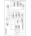
図1に示す温度制御装置100は、アンテナ101、信号処理回路102、充電回路103、蓄電池104、温度センサ108、ヒーター105を有する。信号処理回路102は、変調回路110、復調回路111、第1電源回路113、論理回路114、メモリ回路115、メモリ制御回路116、センサ制御回路117及びヒーター制御回路118を有する。充電回路103は、整流回路120、第2電源回路121、及び充電制御回路122を有する。
A temperature control device 100 illustrated in FIG. 1 includes an
なお本発明の温度制御装置は、アンテナ101において生成された交流電圧を用いて動作を行うことができれば良く、アンテナ101を必ずしも有していなくとも良い。
Note that the temperature control device of the present invention only needs to be able to operate using an AC voltage generated in the
本実施の形態で示す温度制御装置100では、アンテナ101で電波を受信することで生成された電気エネルギーが、充電回路103に供給される。充電回路103では、該電気エネルギーを用いて蓄電池104を充電する。必要に応じて、蓄電池104から温度センサ108、ヒーター105、信号処理回路102に電力が供給される。また、蓄電池104を充電することの他に、信号処理回路102を用いて、外部の通信機器と無線通信が行うことができる。
In the temperature control device 100 described in this embodiment, electric energy generated by receiving radio waves with the
なお、蓄電池104を充電するためにアンテナ101で受信する電波として、外部の電波を利用する。外部の電波として、例えば、クッキングヒーターだと20kHz〜30kHzの電波、高周波加熱装置だと2.45GHzの電波などがある。温度制御装置100は使用する周波数帯に適用させたアンテナ101を設けることによって、電波を受信し、電力を供給する事ができる。
Note that external radio waves are used as radio waves received by the
また、アンテナ101の形状についても、特に限定されない。例えば、線状(例えば、ダイポールアンテナ)、平坦な形状(例えば、パッチアンテナ)等に形成することができる。高周波加熱装置から電波を受信する場合であれば、2.45GHzの波長に合わせた長さにすればよい。周波数が2.45GHzの場合は、半波長ダイポールアンテナを設けるなら約60mm(1/2波長)、モノポールアンテナを設けるなら約30mm(1/4波長)とすれば良い。
Further, the shape of the
図1に示す整流回路120は、アンテナ101が受信した電波を直流電圧に変換する回路であればよい。例えば、半波整流回路、全波整流回路、半波2倍圧整流回路等が用いられる。充電制御回路122は、蓄電池104への過充電を制御するものである。第2電源回路121は、蓄電池104に充電する電圧を制御するもので、蓄電池104の定格電圧などに合わせたものである。
The
なお、本明細書において、蓄電池とは、充電することで連続使用時間を回復することが出来る電池のことをいう。例えば、リチウム電池、好ましくはゲル状の電解質を用いるリチウムポリマー電池や、リチウムイオン電池等を用いることで、小型化が可能である。勿論、充電可能な電池であれば、これらに限定されるものではなく、ニッケル水素電池、ニカド電池等の充放電可能な電池であってもよいし、電気二重層コンデンサのような、大容量コンデンサなどを用いても良い。 Note that in this specification, a storage battery refers to a battery whose continuous use time can be recovered by charging. For example, the size can be reduced by using a lithium battery, preferably a lithium polymer battery using a gel electrolyte, a lithium ion battery, or the like. Of course, as long as it is a rechargeable battery, the battery is not limited to these, and may be a chargeable / dischargeable battery such as a nickel metal hydride battery or a nickel-cadmium battery, or a large capacity capacitor such as an electric double layer capacitor. Etc. may be used.
図1に示す温度センサ108は、被処理物の温度を測定するものであり、代表的な例として、測温抵抗体、サーミスタ、熱電対がある。温度センサ108は、蓄電池104から電力を供給される。温度センサ108が測定した温度情報は、センサ制御回路117に送られ、論理回路114において基準となる温度情報(規定温度情報)と比較される。規定温度情報は、あらかじめメモリ回路115に記憶してあるデータや、外部の信号によりメモリ回路115に書き込まれたデータを使用する。そして、温度センサ108の測定した温度が基準となる温度以上である、もしくは基準となる温度に達していないという比較の結果を、温度制御装置100は外部の通信機器と無線通信を行う。もしくは、温度情報のまま外部の通信機器へ情報を送り、外部の通信機器で規定温度との比較を行っても良い。
A
図1に示すヒーター105は、電気によって熱を発生させるものを使用する。ヒーター105は、蓄電池104から電力が供給される。ヒーター105の形状や種類は、特に限定されない。ヒーターの種類で代表的なものは、電熱線、シーズヒーターが一般的である。蓄電池104の容量や温度制御装置100の大きさに適用させたヒーター105を、搭載することで発熱機能を有する温度制御装置100となる。ヒーター制御回路118は、温度情報を元にヒーター105の発熱制御を行う。温度センサにより測定された被処理物の温度は、論理回路114で規定温度情報と比較される。規定温度情報は、あらかじめメモリ回路115に記憶してあるデータや、外部の信号によりメモリ回路115に書き込まれたデータを使用する。温度センサ108の測定した被処理物の温度が規定温度以上になった場合や規定温度に達していないという情報により、ヒーター制御回路118はヒーター105の発熱を制御する。なお、温度センサ108において、被処理物の温度のみならずヒーター105の温度も検知し、検知されたヒーター105の温度が特定の温度を超えたときに、ヒーター制御回路118がヒーター105の発熱を抑制するようにしてもよい。
As the
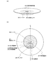
なお図1に示す温度制御装置100は第1保護材106と第2保護材107とで覆われている。図2に、図1で示した温度制御装置100が有するアンテナ101、信号処理回路102、充電回路103、蓄電池104、ヒーター105及び温度センサ108と、第1保護材106と、第2保護材107との位置関係を示す。
The temperature control device 100 shown in FIG. 1 is covered with a first protective material 106 and a second protective material 107. 2 shows an
第1保護材106は、外部の電波から温度制御装置100内部の回路、具体的には信号処理回路102、充電回路103、蓄電池104を保護することが目的であるため、電波吸収材のような電波を通しにくい材料を用いる。例えば電波吸収材として、基材に磁性損失材料を混入させたものを用いることができる。この場合、基材として合成ゴム、ウレタン、磁性損失材料としてカーボン材、フェライト材、カーボニル鉄材を用いればよい。温度制御装置100の使用する周波数帯に適用させた材料を第1保護材106として使用すればよい。2.45GHzでの使用であれば、例えばフェライト材を合成ゴムやウレタンなどに混入させたものを第1保護材106として使用すればよい。
The first protective material 106 is intended to protect the circuit inside the temperature control device 100 from external radio waves, specifically, the
第2保護材107は、温度制御装置100を物理的に保護するものであり、ポリエチレン、ポリプロピレン、ポリ塩化ビニルなどの合成樹脂やセラミック等を用いる。第1保護材106と第2保護材107の材料は、例に挙げた材料に限らず、第1保護材106に挙げた材料を第2保護材107で使用しても良く、第2保護材107に挙げた材料を第1保護材106で使用しても良い。また、第1保護材106と第2保護材107に同じ材料を用いることも可能である。ただし、第1保護材106は電波を通しにくくする必要があり、第2保護材107は電波を通す必要があるため、電波の損失の高い材料を両方に使用した場合は、保護材の厚みや形状に変化を付ける必要がある。電波の損失の高い材料を第1保護材106と第2保護材107の両方に使用する場合は、第1保護材106よりも第2保護材107の厚みを極力薄くすれば良い。例えば第1保護材106及び第2保護材107として、フェライト材と合成ゴムを用いる場合、第1保護材106の厚さを約6mm、第2保護材107の厚さを1〜2mm程度とすれば良い。第1保護材106、第2保護材107は用途に合わせて適当な材料で構成すれば良い。 The second protective material 107 physically protects the temperature control device 100 and uses a synthetic resin such as polyethylene, polypropylene, or polyvinyl chloride, ceramics, or the like. The materials of the first protective material 106 and the second protective material 107 are not limited to the materials mentioned in the example, and the materials listed in the first protective material 106 may be used as the second protective material 107. The materials listed in 107 may be used for the first protective material 106. In addition, the same material can be used for the first protective material 106 and the second protective material 107. However, since the first protective material 106 needs to make it difficult for radio waves to pass through and the second protective material 107 needs to pass radio waves, when materials with high radio wave loss are used for both, It is necessary to change the shape. When a material with a high loss of radio waves is used for both the first protective material 106 and the second protective material 107, the thickness of the second protective material 107 may be made as thin as possible as compared with the first protective material 106. For example, when ferrite material and synthetic rubber are used as the first protective material 106 and the second protective material 107, the thickness of the first protective material 106 is about 6 mm, and the thickness of the second protective material 107 is about 1 to 2 mm. It ’s fine. The first protective material 106 and the second protective material 107 may be made of an appropriate material in accordance with the application.
なお、温度センサ108とヒーター105は、第1保護材106で覆われていても良いし、第1保護材106に加え、第2保護材107でも覆われていても良い。
The
次に、信号処理回路102の動作について説明する。アンテナ101で受信した電波は、整流回路120で直流電圧に変換され、蓄電池104に蓄えられる。蓄電池104は、信号処理回路102の第1電源回路113に電力を供給する。そして、第1電源回路113は、安定化した後の電圧を、変調回路110、論理回路114、メモリ回路115、メモリ制御回路116、センサ制御回路117及びヒーター制御回路118に供給する。
Next, the operation of the
アンテナ101で受信された信号はアンプなどで増幅または波形整形されて、クロック信号として論理回路114に入力される。さらに、電波に含まれる信号は、復調回路111により復調され、データとして論理回路114に入力される。
A signal received by the
また、温度制御装置100の情報を呼び出す際には、論理回路114からの信号を用いて、メモリ制御回路116を制御し、メモリ回路115に記憶されているデータを呼び出す。次にメモリ回路115から呼び出されたデータを論理回路114で加工し、アンプなどで増幅後、変調回路110を動作させる。データの加工はISO14443、ISO15693、ISO18000などの規格に定められた方式に従い加工されるが、通信を行う外部の通信機器との整合性が確保されれば、上記の規格以外を用いてもかまわない。
Further, when calling up the information of the temperature control device 100, the
(実施の形態2)
次に、本発明の温度制御装置の具体的な構成について説明する。
(Embodiment 2)
Next, a specific configuration of the temperature control device of the present invention will be described.
図3に本発明の温度制御装置の一形態を示す。図3(A)は本実施の形態の温度制御装置200の斜視図、図3(B)は上面図に相当する。また図5は、図3(B)の破線A−A’における断面図に相当する。図3に示す温度制御装置200は、食品などの被処理物を載置または収容できる形状を有しており、被処理物と接するように、或いは被処理物に隣接するように、温度センサ201が設けられている。また温度制御装置200は、ヒーター202を有している。ヒーター202は、温度センサ201との間に距離を有するように設けられており、なおかつ被処理物と接するように、或いは被処理物に隣接するように設けられている。
FIG. 3 shows an embodiment of the temperature control device of the present invention. 3A corresponds to a perspective view of the
蓄電池203と、信号処理回路及び充電回路204とは第1保護材205によって覆われている。また蓄電池203と、信号処理回路及び充電回路204と、ヒーター202と、アンテナ206とは、第2保護材207によって覆われている。なお図3では温度センサ201が第2保護材207によって覆われている例を示しているが、温度センサ201は第2保護材207に覆われずに露出していても良い。また図3ではヒーター202が第2保護材207によって覆われているが、第2保護材207によって覆われずに露出していても良い。
The storage battery 203 and the signal processing circuit and charging
また図5に示すように、第1保護材205で覆われている蓄電池203と、信号処理回路及び充電回路204とは、複数の配線208によって、温度センサ201と、ヒーター202とに接続されている。そして図5では、第2保護材207で覆われている領域には、樹脂などの充填材209が設けられている。充填材209は必ずしも設ける必要はないが、第2保護材207で覆われている領域において空間が形成されている場合は、該空間に充填材209を設けることで、温度制御装置の物理的な強度を高めることができる。
As shown in FIG. 5, the storage battery 203 covered with the first protective material 205, the signal processing circuit and the charging
なお図3では、温度制御装置200が、食品などの被処理物を載置または収容できる形状を有する場合を示しているが、本発明はこの構成に限定されない。例えば温度制御装置200を、被処理物を載置または収容するための器具に取り付けて用いる場合、必ずしも被処理物を載置または収容できる形状を有していなくとも良い。被処理物が食品である場合、例えば、皿、お椀、弁当箱、タッパ等に装着する。本発明品の装着された容器に食品を入れ、高周波加熱装置で食品を加熱すれば良い。
Note that FIG. 3 shows a case where the
次に本発明の温度制御装置を、高周波加熱装置内で使用する場合について、図4を用いて説明する。 Next, the case where the temperature control device of the present invention is used in a high-frequency heating device will be described with reference to FIG.
本発明は、アンテナにより外部の電波を受け取り、蓄電池を充電する。アンテナは、高周波加熱装置300から電波を受信する場合であれば、2.45GHzの波長に合わせた長さにすればよい。周波数が2.45GHzの場合は、半波長ダイポールアンテナを設けるなら約60mm(1/2波長)、モノポールアンテナを設けるなら約30mm(1/4波長)とすれば良い。また、形状に限定はなく、2.45GHzに対応したアンテナであれば良い。
In the present invention, an external radio wave is received by an antenna and a storage battery is charged. If the antenna receives radio waves from the high-
図4(A)に示すように、高周波加熱装置300からの電波を温度制御装置200が有するアンテナが受け取る。アンテナで受信した電波は、整流回路で直流電圧に変換され、蓄電池に蓄えられる。そして蓄電池から温度センサ、ヒーター、信号処理回路に電力が供給される。温度制御装置200と無線通信を行うためには、高周波加熱装置300も無線通信が行える構造を有している必要がある。温度制御装置200は、温度制御装置200内で温度情報を処理し、高周波加熱装置300を制御する。もしくは、高周波加熱装置300が温度制御装置200より受信した情報によって動作を制御する。蓄電池により電力を供給された温度センサは、被処理物の温度を測定する。規定温度以上になったときに、高周波加熱装置300からの高周波の発生を停止させる。温度制御装置200は被処理物の加熱中に蓄電池を充電する。
As shown in FIG. 4A, an antenna included in the
次に図4(B)に示すように高周波加熱装置での調理が終わった後は、充電された蓄電池を用いてヒーターを動作させて、被処理物の保温を行うことが可能である。温度制御装置200は高周波加熱装置300の外でも無線通信を行うことが可能であるため、ヒーターなどを無線で制御することもできる。この場合は、2.45GHzで無線通信を行うリーダ、またはリーダライタと呼ばれる質問器が必要である。
Next, as shown in FIG. 4B, after cooking in the high-frequency heating apparatus is completed, the heater can be operated using the charged storage battery to keep the object to be processed warm. Since the
以上のように、本発明の温度制御装置は、無線で充電した蓄電池を使用して動作する。蓄電池を充電しておくことによって、電波を受けていないときにでも、温度センサ、ヒーターへの電力の供給を行うことが可能である。 As described above, the temperature control device of the present invention operates using a storage battery charged wirelessly. By charging the storage battery, it is possible to supply power to the temperature sensor and the heater even when not receiving radio waves.
100 温度制御装置
101 アンテナ
102 信号処理回路
103 充電回路
104 蓄電池
105 ヒーター
106 保護材
107 保護材
108 温度センサ
110 変調回路
111 復調回路
113 電源回路
114 論理回路
115 メモリ回路
116 メモリ制御回路
117 センサ制御回路
118 ヒーター制御回路
120 整流回路
121 電源回路
122 充電制御回路
200 温度制御装置
201 温度センサ
202 ヒーター
203 蓄電池
204 充電回路
205 保護材
206 アンテナ
207 保護材
208 配線
209 充填材
300 高周波加熱装置
DESCRIPTION OF SYMBOLS 100
Claims (3)
前記温度センサによって検知された温度を、基準の温度と比較する信号処理回路と、
前記電波を受信することで電気エネルギーを生成するアンテナと、
前記電気エネルギーにより、充電が行われる蓄電池と、
前記蓄電池の充電を制御する充電回路と、
前記蓄電池から電力が供給され、かつ前記信号処理回路による比較の結果に従って、前記被処理物を前記基準の温度に近づくように加熱するヒーターと、
前記信号処理回路、前記蓄電池及び前記充電回路を覆う第1保護材と、
前記信号処理回路、前記蓄電池、前記充電回路、前記温度センサ、前記ヒーター、前記アンテナ及び前記第1保護材を覆う第2保護材と、
を有することを特徴とする温度制御装置。 A temperature sensor for detecting the temperature of the workpiece heated by the radio wave emitted from the high-frequency generator;
A signal processing circuit that compares a temperature detected by the temperature sensor with a reference temperature;
An antenna that generates electrical energy by receiving the radio waves;
A storage battery that is charged by the electrical energy;
A charging circuit for controlling charging of the storage battery;
A heater that is supplied with electric power from the storage battery and that heats the workpiece to approach the reference temperature according to the result of the comparison by the signal processing circuit;
A first protective material covering the signal processing circuit, the storage battery and the charging circuit;
Said signal processing circuit, said battery, said charging circuit, said temperature sensor, and the heater, the second protective member covering the antenna and the first protective material,
A temperature control device comprising:
前記第2保護材は合成樹脂またはセラミックであることを特徴とする温度制御装置。The temperature control device, wherein the second protective material is synthetic resin or ceramic.
Priority Applications (1)
| Application Number | Priority Date | Filing Date | Title |
|---|---|---|---|
| JP2007324181A JP5100355B2 (en) | 2006-12-22 | 2007-12-17 | Temperature control device |
Applications Claiming Priority (3)
| Application Number | Priority Date | Filing Date | Title |
|---|---|---|---|
| JP2006345555 | 2006-12-22 | ||
| JP2006345555 | 2006-12-22 | ||
| JP2007324181A JP5100355B2 (en) | 2006-12-22 | 2007-12-17 | Temperature control device |
Publications (3)
| Publication Number | Publication Date |
|---|---|
| JP2008173464A JP2008173464A (en) | 2008-07-31 |
| JP2008173464A5 JP2008173464A5 (en) | 2011-01-20 |
| JP5100355B2 true JP5100355B2 (en) | 2012-12-19 |
Family
ID=39541374
Family Applications (1)
| Application Number | Title | Priority Date | Filing Date |
|---|---|---|---|
| JP2007324181A Expired - Fee Related JP5100355B2 (en) | 2006-12-22 | 2007-12-17 | Temperature control device |
Country Status (2)
| Country | Link |
|---|---|
| US (2) | US8759725B2 (en) |
| JP (1) | JP5100355B2 (en) |
Families Citing this family (32)
| Publication number | Priority date | Publication date | Assignee | Title |
|---|---|---|---|---|
| JP5312810B2 (en) * | 2007-01-19 | 2013-10-09 | 株式会社半導体エネルギー研究所 | Charger |
| JP2009087928A (en) * | 2007-09-13 | 2009-04-23 | Semiconductor Energy Lab Co Ltd | Semiconductor device and manufacturing method therefor |
| US20110056215A1 (en) * | 2009-09-10 | 2011-03-10 | Qualcomm Incorporated | Wireless power for heating or cooling |
| US8759721B1 (en) * | 2010-11-02 | 2014-06-24 | Piatto Technologies, Inc. | Heated or cooled dishwasher safe dishware and drinkware |
| US11950726B2 (en) | 2010-11-02 | 2024-04-09 | Ember Technologies, Inc. | Drinkware container with active temperature control |
| US9814331B2 (en) | 2010-11-02 | 2017-11-14 | Ember Technologies, Inc. | Heated or cooled dishware and drinkware |
| US10010213B2 (en) | 2010-11-02 | 2018-07-03 | Ember Technologies, Inc. | Heated or cooled dishware and drinkware and food containers |
| US9035222B2 (en) * | 2010-11-02 | 2015-05-19 | Oromo Technologies, Inc. | Heated or cooled dishware and drinkware |
| EP2636118B1 (en) * | 2010-11-02 | 2019-07-17 | Ember Technologies, Inc. | Heated or cooled dishwasher safe dishware and drinkware |
| GB201109495D0 (en) * | 2011-06-07 | 2011-07-20 | Thomson Wendy | Food heater |
| JP5244229B2 (en) * | 2011-12-26 | 2013-07-24 | シャープ株式会社 | Cooker |
| KR102025722B1 (en) | 2012-05-02 | 2019-09-26 | 가부시키가이샤 한도오따이 에네루기 켄큐쇼 | Temperature sensor circuit and semiconductor device including temperature sensor circuit |
| TW201433214A (en) * | 2013-02-01 | 2014-08-16 | Primax Electronics Ltd | Wireless heat generation device and wireless heat generation system |
| US20140238250A1 (en) * | 2013-02-28 | 2014-08-28 | Wki Holding Company, Inc. | Microwavable Heating Element and Composition |
| WO2015056252A2 (en) * | 2013-10-18 | 2015-04-23 | Oglesby & Butler Research & Development Limited | An evaporator |
| TWI474769B (en) * | 2014-03-04 | 2015-02-21 | Cheng Uei Prec Ind Co Ltd | Power device and assembling method thereof |
| CA2955921C (en) * | 2014-06-23 | 2018-09-25 | Ember Technologies, Inc. | Heated or cooled dishware and drinkware |
| US11141011B2 (en) * | 2014-10-28 | 2021-10-12 | Tempra Technology, Inc. | Heat retaining dish assembly and method of heating same |
| US9782036B2 (en) | 2015-02-24 | 2017-10-10 | Ember Technologies, Inc. | Heated or cooled portable drinkware |
| WO2017151362A1 (en) | 2016-02-29 | 2017-09-08 | Ember Technologies, Inc. | Liquid container and module for adjusting temperature of liquid in container |
| WO2017192396A1 (en) | 2016-05-02 | 2017-11-09 | Ember Technologies, Inc. | Heated or cooled drinkware |
| WO2017197026A1 (en) | 2016-05-12 | 2017-11-16 | Ember Technologies, Inc. | Drinkware and plateware and active temperature control module for same |
| KR20180035662A (en) | 2016-09-29 | 2018-04-06 | 엠버 테크놀로지스 인코포레이티드 | Heated or cooled drinkware |
| US9995529B1 (en) * | 2016-12-08 | 2018-06-12 | Nova Laboratories | Temperature-regulating containment system |
| US20200146477A1 (en) * | 2017-07-13 | 2020-05-14 | Ember Technologies, Inc. | Plateware with active temperature control |
| US20190110643A1 (en) * | 2017-10-14 | 2019-04-18 | Gloria Contreras | Smart charger plate |
| EP3745930B1 (en) | 2018-01-31 | 2021-12-29 | Ember Technologies, Inc. | Actively heated or cooled infant bottle system |
| CN112136012A (en) | 2018-04-19 | 2020-12-25 | 恩伯技术公司 | Portable cooler with active temperature control |
| CA3125017A1 (en) | 2019-01-11 | 2020-07-16 | Ember Technologies, Inc. | Portable cooler with active temperature control |
| US11668508B2 (en) | 2019-06-25 | 2023-06-06 | Ember Technologies, Inc. | Portable cooler |
| KR20220027144A (en) | 2019-06-25 | 2022-03-07 | 엠버 테크놀로지스 인코포레이티드 | portable cooler |
| US11162716B2 (en) | 2019-06-25 | 2021-11-02 | Ember Technologies, Inc. | Portable cooler |
Family Cites Families (56)
| Publication number | Priority date | Publication date | Assignee | Title |
|---|---|---|---|---|
| US3931494A (en) * | 1975-04-01 | 1976-01-06 | Barbara Fisher | Rechargeable battery heating unit |
| US4219715A (en) * | 1978-07-24 | 1980-08-26 | Jurgensen Peter D | Microwave powered turntable for microwave ovens |
| CA1272502A (en) * | 1986-07-07 | 1990-08-07 | Leonard Ineson | Heated cup |
| DE68905710T2 (en) * | 1988-08-12 | 1993-07-08 | Nissin Food Products Ltd | SELF-WARMING CONTAINER. |
| US4967061A (en) * | 1989-10-10 | 1990-10-30 | Sonne Medical, Inc. | Heated basin |
| US4980539A (en) * | 1990-02-02 | 1990-12-25 | Walton Charles A | Portable warmer |
| US5300875A (en) * | 1992-06-08 | 1994-04-05 | Micron Technology, Inc. | Passive (non-contact) recharging of secondary battery cell(s) powering RFID transponder tags |
| JP2905017B2 (en) * | 1992-11-16 | 1999-06-14 | 三菱電機株式会社 | High frequency heating equipment |
| JPH0815117B2 (en) | 1993-06-28 | 1996-02-14 | 川重防災工業株式会社 | Sealing structure of dielectric heating device |
| WO1997003539A1 (en) * | 1995-07-07 | 1997-01-30 | Marvin Fabrikant | Heater for a liquid or gel container |
| JPH10127981A (en) | 1996-10-30 | 1998-05-19 | Sharp Corp | Electric washing machine |
| JPH10178293A (en) | 1996-12-16 | 1998-06-30 | Kitagawa Ind Co Ltd | Computer system |
| GB9705870D0 (en) * | 1997-03-21 | 1997-05-07 | Philips Electronics Nv | Charging of secondary cells using transmitted microwave energy |
| US6108489A (en) * | 1997-10-17 | 2000-08-22 | Phase Change Laboratories, Inc. | Food warning device containing a rechargeable phase change material |
| JPH11148652A (en) * | 1997-11-19 | 1999-06-02 | Matsushita Electric Ind Co Ltd | Heater |
| JP2001235157A (en) * | 2000-02-24 | 2001-08-31 | Sanyo Electric Co Ltd | High frequency heating device |
| US6469282B1 (en) * | 2000-07-28 | 2002-10-22 | General Electric Company | Boil dry detection in cooking appliances |
| JP2003158394A (en) * | 2001-11-20 | 2003-05-30 | Matsushita Electric Ind Co Ltd | High frequency heating device |
| JP4030787B2 (en) * | 2002-03-04 | 2008-01-09 | 東京エレクトロン株式会社 | Substrate heating method, substrate heating apparatus, coating and developing apparatus |
| JP2003299255A (en) | 2002-04-02 | 2003-10-17 | Nippon Telegr & Teleph Corp <Ntt> | Portable battery charger |
| JP2004138331A (en) | 2002-10-18 | 2004-05-13 | Hitachi Ltd | Container with wireless ic tag and food cooker |
| US7075442B2 (en) * | 2003-07-07 | 2006-07-11 | Mastrad Sa | Food temperature monitoring device |
| US7737658B2 (en) * | 2003-10-27 | 2010-06-15 | Sony Corporation | Battery packs having a charging mode and a discharging mode |
| JP2005242629A (en) | 2004-02-26 | 2005-09-08 | Matsushita Electric Ind Co Ltd | Non-contact information storage medium and cooking appliance |
| JP4611093B2 (en) * | 2004-05-12 | 2011-01-12 | セイコーインスツル株式会社 | Radio power generation circuit |
| US7736964B2 (en) * | 2004-11-22 | 2010-06-15 | Semiconductor Energy Laboratory Co., Ltd. | Semiconductor device, and method for manufacturing the same |
| JP2006166522A (en) | 2004-12-03 | 2006-06-22 | Oyama Yoshio | Current supply method |
| US7176426B2 (en) * | 2005-03-18 | 2007-02-13 | Ramirez Juan Jose | Integrated microwaveable heat storage device |
| US7333910B2 (en) * | 2005-04-26 | 2008-02-19 | Semiconductor Energy Laboratory Co., Ltd. | Fire sensing method and fire sensing system using wireless chip for sensing fire |
| WO2006129742A1 (en) * | 2005-05-30 | 2006-12-07 | Semiconductor Energy Laboratory Co., Ltd. | Semiconductor device |
| KR101299932B1 (en) * | 2006-03-10 | 2013-08-27 | 가부시키가이샤 한도오따이 에네루기 켄큐쇼 | Semiconductor device |
| KR101362954B1 (en) * | 2006-03-10 | 2014-02-12 | 가부시키가이샤 한도오따이 에네루기 켄큐쇼 | Semiconductor device and method for operating the same |
| WO2007108371A1 (en) * | 2006-03-15 | 2007-09-27 | Semiconductor Energy Laboratory Co., Ltd. | Semiconductor device |
| JP2007312932A (en) * | 2006-05-24 | 2007-12-06 | Nippon Telegr & Teleph Corp <Ntt> | Case |
| WO2007139205A1 (en) * | 2006-05-31 | 2007-12-06 | Semiconductor Energy Laboratory Co., Ltd. | Semiconductor device and ic label, ic tag, and ic card having the same |
| US8132026B2 (en) * | 2006-06-02 | 2012-03-06 | Semiconductor Energy Laboratory Co., Ltd. | Power storage device and mobile electronic device having the same |
| US7714535B2 (en) * | 2006-07-28 | 2010-05-11 | Semiconductor Energy Laboratory Co., Ltd. | Power storage device |
| US8344888B2 (en) * | 2006-08-31 | 2013-01-01 | Semiconductor Energy Laboratory Co., Ltd. | Semiconductor device |
| EP1895450B1 (en) * | 2006-08-31 | 2014-03-05 | Semiconductor Energy Laboratory Co., Ltd. | Semiconductor device and power receiving device |
| US8463332B2 (en) * | 2006-08-31 | 2013-06-11 | Semiconductor Energy Laboratory Co., Ltd. | Wireless communication device |
| US10168801B2 (en) * | 2006-08-31 | 2019-01-01 | Semiconductor Energy Laboratory Co., Ltd. | Electronic pen and electronic pen system |
| US7764046B2 (en) * | 2006-08-31 | 2010-07-27 | Semiconductor Energy Laboratory Co., Ltd. | Power storage device and semiconductor device provided with the power storage device |
| JP5052079B2 (en) * | 2006-09-08 | 2012-10-17 | 株式会社半導体エネルギー研究所 | Sensor device and containers having the same |
| EP1901058A3 (en) * | 2006-09-13 | 2010-02-17 | Semiconductor Energy Laboratory Co., Ltd. | Examination element and examination container for testing liquid samples |
| US7965180B2 (en) * | 2006-09-28 | 2011-06-21 | Semiconductor Energy Laboratory Co., Ltd. | Wireless sensor device |
| US7839124B2 (en) * | 2006-09-29 | 2010-11-23 | Semiconductor Energy Laboratory Co., Ltd. | Wireless power storage device comprising battery, semiconductor device including battery, and method for operating the wireless power storage device |
| US7881693B2 (en) * | 2006-10-17 | 2011-02-01 | Semiconductor Energy Laboratory Co., Ltd. | Semiconductor device |
| US8099140B2 (en) * | 2006-11-24 | 2012-01-17 | Semiconductor Energy Laboratory Co., Ltd. | Wireless power supply system and wireless power supply method |
| US7830113B2 (en) * | 2006-11-28 | 2010-11-09 | Semiconductor Energy Laboratory Co., Ltd. | Semiconductor device, communication system, and method of charging the semiconductor device |
| JP2008165744A (en) * | 2006-12-07 | 2008-07-17 | Semiconductor Energy Lab Co Ltd | Semiconductor device |
| JP2008181634A (en) * | 2006-12-26 | 2008-08-07 | Semiconductor Energy Lab Co Ltd | Semiconductor device |
| KR101588579B1 (en) * | 2006-12-27 | 2016-01-26 | 가부시키가이샤 한도오따이 에네루기 켄큐쇼 | Switch device and power supply control system |
| JP5178181B2 (en) * | 2006-12-27 | 2013-04-10 | 株式会社半導体エネルギー研究所 | Display device |
| US20080158217A1 (en) * | 2006-12-28 | 2008-07-03 | Semiconductor Energy Laboratory Co., Ltd. | Display device |
| JP5312810B2 (en) * | 2007-01-19 | 2013-10-09 | 株式会社半導体エネルギー研究所 | Charger |
| US20140149064A1 (en) * | 2012-11-29 | 2014-05-29 | Animaware Ltd | Temperature monitor |
-
2007
- 2007-12-17 JP JP2007324181A patent/JP5100355B2/en not_active Expired - Fee Related
- 2007-12-20 US US12/003,124 patent/US8759725B2/en not_active Expired - Fee Related
-
2014
- 2014-06-06 US US14/297,887 patent/US9629205B2/en active Active
Also Published As
| Publication number | Publication date |
|---|---|
| US8759725B2 (en) | 2014-06-24 |
| US9629205B2 (en) | 2017-04-18 |
| JP2008173464A (en) | 2008-07-31 |
| US20140284324A1 (en) | 2014-09-25 |
| US20080149624A1 (en) | 2008-06-26 |
Similar Documents
| Publication | Publication Date | Title |
|---|---|---|
| JP5100355B2 (en) | Temperature control device | |
| US11056916B2 (en) | Transmission coil module for wireless power transmitter | |
| US20220115908A1 (en) | System and Method for Inductive Charging of Portable Devices | |
| US8339096B2 (en) | Wireless power receiving device | |
| JP2020522157A (en) | Near-field antenna for storing energy in near-field distance with minimal far-field gain | |
| US8629654B2 (en) | System and method for inductive charging of portable devices | |
| EP1946426B1 (en) | Non-contact charger available of wireless data and power transmission, charging battery-pack and mobile device using non-contact charger | |
| EP2546956B1 (en) | Method for wireless charging of a mobile terminal and mobile terminal for same | |
| AU2015307027B2 (en) | Battery pack including an indicator circuit | |
| CN108337920A (en) | Multi-coil wireless charging method and its equipment and system | |
| WO2015088875A1 (en) | Wireless charging of clothing and smart fabrics | |
| WO2016054019A1 (en) | Wireless heat devices | |
| WO2015020991A1 (en) | Wireless electrical temperature regulator for food and beverages | |
| US9521926B1 (en) | Wireless electrical temperature regulator for food and beverages | |
| KR102576401B1 (en) | Foreign Object Detection Method and Apparatus and System therefor | |
| KR20170051139A (en) | Apparatus for receiving wireless power | |
| US20180294673A1 (en) | Wireless power transmitter | |
| KR101769050B1 (en) | Transmitting Coil Module For Wireless Power Transmitter | |
| CN105393570A (en) | Method and apparatus for authentication in wireless power transmission system | |
| CN108233555A (en) | It can carry out the mechanism of wireless charging and heating and device and its control method with wireless charging and heating function | |
| KR20190011638A (en) | Method for Preventing Over-temperature for Each of Wireless Power Receiver and Wireless Power Transmitter | |
| KR20170124185A (en) | Apparatus for receiving wireless power | |
| KR20190030019A (en) | Method for Transmitting Power for Each of Wireless Power Receiver and Wireless Power Transmitter | |
| KR20180013088A (en) | Wireless Power Transmitter and Wireless Power Receiver | |
| KR20180011606A (en) | Wireless Power Transmitter and Wireless Power Receiver |
Legal Events
| Date | Code | Title | Description |
|---|---|---|---|
| A521 | Request for written amendment filed |
Free format text: JAPANESE INTERMEDIATE CODE: A523 Effective date: 20101124 |
|
| A621 | Written request for application examination |
Free format text: JAPANESE INTERMEDIATE CODE: A621 Effective date: 20101124 |
|
| A977 | Report on retrieval |
Free format text: JAPANESE INTERMEDIATE CODE: A971007 Effective date: 20120803 |
|
| TRDD | Decision of grant or rejection written | ||
| A01 | Written decision to grant a patent or to grant a registration (utility model) |
Free format text: JAPANESE INTERMEDIATE CODE: A01 Effective date: 20120918 |
|
| A01 | Written decision to grant a patent or to grant a registration (utility model) |
Free format text: JAPANESE INTERMEDIATE CODE: A01 |
|
| A61 | First payment of annual fees (during grant procedure) |
Free format text: JAPANESE INTERMEDIATE CODE: A61 Effective date: 20120925 |
|
| FPAY | Renewal fee payment (event date is renewal date of database) |
Free format text: PAYMENT UNTIL: 20151005 Year of fee payment: 3 |
|
| R150 | Certificate of patent or registration of utility model |
Free format text: JAPANESE INTERMEDIATE CODE: R150 |
|
| FPAY | Renewal fee payment (event date is renewal date of database) |
Free format text: PAYMENT UNTIL: 20151005 Year of fee payment: 3 |
|
| R250 | Receipt of annual fees |
Free format text: JAPANESE INTERMEDIATE CODE: R250 |
|
| R250 | Receipt of annual fees |
Free format text: JAPANESE INTERMEDIATE CODE: R250 |
|
| R250 | Receipt of annual fees |
Free format text: JAPANESE INTERMEDIATE CODE: R250 |
|
| LAPS | Cancellation because of no payment of annual fees |