JP5100280B2 - Image forming apparatus - Google Patents
Image forming apparatus Download PDFInfo
- Publication number
- JP5100280B2 JP5100280B2 JP2007248181A JP2007248181A JP5100280B2 JP 5100280 B2 JP5100280 B2 JP 5100280B2 JP 2007248181 A JP2007248181 A JP 2007248181A JP 2007248181 A JP2007248181 A JP 2007248181A JP 5100280 B2 JP5100280 B2 JP 5100280B2
- Authority
- JP
- Japan
- Prior art keywords
- power
- engine control
- control cpu
- engine
- image forming
- Prior art date
- Legal status (The legal status is an assumption and is not a legal conclusion. Google has not performed a legal analysis and makes no representation as to the accuracy of the status listed.)
- Expired - Fee Related
Links
Images


Landscapes
- Accessory Devices And Overall Control Thereof (AREA)
- Control Or Security For Electrophotography (AREA)
Description
本発明は、画像形成装置に関する。 The present invention relates to an image forming apparatus.
近年の画像形成装置は、環境問題やエネルギー問題における対策として、待機時には省エネ状態または省エネモードと呼ぶ状態を有し消費電力を低減する機能を備えている。省エネモードにおいて、画像形成装置はスタンバイ状態とは異なり、定着装置の保温の停止、および画像形成装置に接続される外部機器、オプション装置などの通電も遮断して消費電力を低減する。 2. Description of the Related Art Recent image forming apparatuses have a function of reducing power consumption in a state called an energy saving state or an energy saving mode during standby as a countermeasure against environmental problems and energy problems. In the energy saving mode, unlike the standby state, the image forming apparatus reduces power consumption by stopping the heat retention of the fixing device and cutting off the energization of external devices and optional devices connected to the image forming apparatus.
さらに近年は制御CPUへの通電も遮断し、消費電力の削減を達成するシステムも多くなっている。ホストコンピュータと接続し画像情報を受け付けるコントローラと、画像形成部の動作を制御するエンジン部とを有するシステムで、コントローラのみを通電してエンジン部の通電を止めるシステムも増えている。 Furthermore, in recent years, there are many systems that cut off the power supply to the control CPU and achieve reduction of power consumption. An increasing number of systems are connected to a host computer to receive image information and have an engine unit that controls the operation of the image forming unit and energize only the controller to stop energization of the engine unit.
例えば、更なる電力消費を削減する為にコントローラにおいても必要なデバイスにのみ電力供給を行うことで省エネモードの効率を高める技術が開示されている。具体的には、コントローラに設けられているホストコンピュータとのデータ通信を司るインタフェース(I/F)のみに給電を行い、エンジン部との通信や画像処理などの高度な制御を司る部分への給電を停止させる技術が提案されている。
For example, techniques to increase the efficiency of energy-saving mode is disclosed by performing the required devices to only the power supply in the controller to reduce the additional power consumption. Specifically, power is supplied only to the interface (I / F) that controls data communication with the host computer provided in the controller, and power is supplied to the parts that control advanced communication such as communication with the engine and image processing. A technique for stopping the system has been proposed.
また、特許文献1によれば、省エネ状態からの復帰時の装置の立ち上げ動作を、電源オン時の装置の立ち上げ動作と異ならせる省エネ復帰方法が開示されている。省エネ用CPUで、省エネ状態からの復帰要因の発生を検出すると、復帰要因の検出結果を自ポートに保持した後に、本体用CPUを起動する。起動された本体用CPUは、省エネ用CPUのポートを読み、復帰要因の検出結果の有無を判別する。復帰要因の検出結果の有無に応じて異なる初期化手順により、ファクシミリ装置の初期化を行う。例えば、復帰要因を検出していなければ、本体用CPUは、ファクシミリ装置の電源スイッチがオンされた場合の初期化手順、すなわち、感光体のクリーニングを含む初期化動作を行う。また、復帰要因が検出されていれば、復帰要因に対応して予め定められた初期化手順により装置の初期化を行うことが提案されている。
しかしながら、上記省エネモード時にホストコンピュータとのデータ通信を司るインタフェース(I/F)のみに給電を行う画像形成装置においては、省エネモード時に、エンジン部への通電と、エンジン部のON/OFFを司るメイン制御ブロックへの通電までもが遮断される。エンジン部の制御CPUは、オフからオンに状態変化した場合、画像形成装置の電源投入時の電源オンであるのか、省エネモードからの復帰による電源オンであるのかの区別が付かない。メイン制御ブロックから電源投入時の電源オンであるのか、省エネモードからの復帰による電源オンであるのかの区別をつけるための指示を受けない限り、エンジン部の制御CPUは適切な起動制御が行えないという点が課題である。
However, in the image forming apparatus that supplies power only to the interface (I / F) that controls data communication with the host computer in the energy saving mode, it controls energization of the engine unit and ON / OFF of the engine unit in the energy saving mode. Even the energization of the main control block is shut off. When the control CPU of the engine unit changes from off to on, there is no distinction between whether the image forming apparatus is powered on when the power is turned on or when the power is turned on by returning from the energy saving mode. The engine control CPU cannot perform appropriate start-up control unless it receives an instruction from the main control block to distinguish between power-on at power-on and power-on by returning from the energy-saving mode. That is the problem.
従来の画像形成装置において電源ON時のエンジン部の起動は、メイン制御ブロックの起動後に行われている。エンジン部の制御CPUが省エネモードからの復帰により起動する場合でも、通常の電源ON時の起動処理と同様の処理を行うと、メイン制御ブロックの起動からエンジン部のイニシャライズ終了までに多くの時間を要することになる。 In the conventional image forming apparatus, the engine unit is activated when the power is turned on after the main control block is activated. Even when the control CPU of the engine unit is activated by returning from the energy-saving mode, if the same process as the normal start-up process is performed, a lot of time is required from the start of the main control block to the end of initialization of the engine unit. It will take.
また、特許文献1に開示されたエンジン部の通電を停止させる省エネモードを有する画像形成装置においては、エンジン部の起動時に画像形成装置の電源オンであるのか、省エネモードからの復帰によるオンであるのかの区別はエンジン部自身では付かない。従って、省エネ時においてもオフにならないコントローラ(メイン制御ブロック)からの指示を受けない限り、エンジン部の制御CPUは適切な起動処理を行うことができない。
In addition, in the image forming apparatus having the energy saving mode for stopping the energization of the engine unit disclosed in Patent Document 1 , the power of the image forming apparatus is turned on when the engine unit is started, or is turned on by returning from the energy saving mode. No distinction is made by the engine part itself. Therefore, the control CPU of the engine unit cannot perform an appropriate start-up process unless receiving an instruction from a controller (main control block) that does not turn off even during energy saving.
本発明は、電源投入による起動か、省エネモードからの復帰による起動かを判定し、この判定結果に従い、エンジン制御CPUにおける起動処理の切り替えを制御することが可能な画像形成技術の提供を目的とする。 SUMMARY OF THE INVENTION An object of the present invention is to provide an image forming technique capable of determining whether to start by turning on the power or starting from the energy saving mode, and to control switching of start processing in the engine control CPU according to the determination result. To do.
本発明に係る画像形成装置は、ホストコンピュータから画像情報を受信し、当該画像情報をエンジン部に送信するコントローラと、当該コントローラから受信した前記画像情報に基づく画像形成を画像形成手段に実行させるエンジン部と、を有する画像形成装置であって、
前記コントローラは、
前記ホストコンピュータとの通信と、当該画像形成装置の動作モードの切り替えと、を制御するサブ制御手段と、
前記サブ制御手段による前記動作モードの切り替えに従い、前記エンジン部の動作を制御するメイン制御手段と、を備え
前記エンジン部は、
前記画像形成手段の動作を制御するエンジン制御手段と、
電源が投入され、前記コントローラに電力が供給された際、前記コントローラへの電力供給とは独立に、前記電源から前記エンジン制御手段に電力を供給する第1制御回路と、
通常の電力消費の動作モードから低消費電力の省エネモードへの移行時、前記メイン制御手段から出力される出力信号によって、前記電源から前記エンジン制御手段に供給される電力をオフにし、前記省エネモードから前記通常の電力消費の動作モードへの移行時、前記メイン制御手段から出力される出力信号によって、前記電源から前記エンジン制御手段に供給される電力をオンにする第2制御回路と、
前記エンジン制御手段の起動が、電源投入による起動か、前記省エネモードから前記通常の電力消費の動作モードへの復帰による起動か、を判定するための判定回路と、を備え、
前記エンジン制御手段は、前記判定回路が電源投入による起動を示している場合、第1の起動処理を実行し、前記判定回路が前記通常の電力消費の動作モードへの復帰による起動を示している場合、前記第1の起動処理より処理時間の短い第2の起動処理を実行し、
前記判定回路は、前記電源がオフにされると当該判定回路を構成する容量性素子の電荷が放電されるように構成され、前記電源がオンの状態で、前記容量性素子には電荷が蓄えられる様に構成されていることを特徴とする。
An image forming apparatus according to the present invention includes a controller that receives image information from a host computer and transmits the image information to an engine unit, and an engine that causes an image forming unit to perform image formation based on the image information received from the controller. An image forming apparatus comprising:
The controller is
Sub-control means for controlling communication with the host computer and switching of the operation mode of the image forming apparatus;
Main control means for controlling the operation of the engine unit in accordance with the switching of the operation mode by the sub-control means, the engine unit,
Engine control means for controlling the operation of the image forming means;
Power is turned on and when the power is supplied to the controller, independently of the power supply to the controller, a first control circuit for supplying electric power to the engine control unit from said power source,
When shifting from the normal power consumption operation mode to the low power consumption energy saving mode, the power supplied from the power source to the engine control means is turned off by the output signal output from the main control means , and the energy saving mode is set. A second control circuit for turning on the power supplied from the power source to the engine control means by an output signal output from the main control means at the time of transition to the normal power consumption operation mode ;
Starting the engine control unit, or power is turned on for startup, and a determination circuit for determining a start or, by a return to the operation mode of the normal power consumption from the power saving mode,
The engine control means executes a first activation process when the determination circuit indicates activation upon power-on, and the determination circuit indicates activation upon return to the normal power consumption operation mode. A second startup process having a processing time shorter than that of the first startup process,
The determination circuit is configured such that when the power is turned off, the charge of the capacitive element constituting the determination circuit is discharged, and the charge is stored in the capacitive element when the power is on. It is comprised so that it may be.
本発明によれば、電源投入による起動か、省エネモードからの復帰による起動かを判定し、この判定結果に従い、エンジン制御CPUにおける起動処理の切り替えを制御することが可能になる。 According to the present invention, it is possible to determine whether the start-up is performed by turning on the power or the return from the energy-saving mode, and it is possible to control switching of the start-up process in the engine control CPU according to the determination result.
以下、図面を参照して、本発明の好適な実施形態を例示的に詳しく説明する。ただし、この実施の形態に記載されている構成要素はあくまで例示であり、本発明の技術的範囲は、特許請求の範囲によって確定されるのであって、以下の個別の実施形態によって限定されるわけではない。 Hereinafter, exemplary embodiments of the present invention will be described in detail with reference to the drawings. However, the constituent elements described in this embodiment are merely examples, and the technical scope of the present invention is determined by the scope of claims, and is limited by the following individual embodiments. is not.
<第1実施形態>
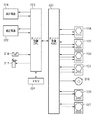
図2は、本発明の実施形態にかかる画像形成装置101の概略的な構成を示す図である。画像形成装置101は、用紙カセット102、給紙ローラ103、トップセンサ123、転写ベルト駆動ローラ104、転写ベルト105、イエロー、マゼンタ、シアン、ブラックの感光ドラム106〜109を備える。また、画像形成装置101は、各色用の転写ローラ110〜113、イエロー、マゼンタ、シアン、ブラックのカートリッジ114〜117を備える。更に、画像形成装置101は、イエロー、マゼンタ、シアン、ブラックの光学ユニット118〜121、および定着ユニット122を備えている。
<First Embodiment>
FIG. 2 is a diagram showing a schematic configuration of the
画像形成装置101は、電子写真プロセスにより記録材上にイエロー、マゼンタ、シアン、ブラックの画像を重ねて転写し、定着ローラを含む定着ユニット122によってトナー画像を温度制御することにより熱定着させる。各色の光学ユニット118〜121は、感光ドラム106〜109の表面をレーザビームによって露光走査して潜像を形成するよう構成されている。これら一連の画像形成動作は搬送される記録材上のあらかじめ決まった位置から画像が転写されるよう同期がとられている。
The
更に、画像形成装置101は記録材である記録紙を給紙、搬送する給紙モータを備え、給紙された記録紙は、転写ベルト、定着ローラへと搬送されながらその表面上に所望の像が形成される。
Further, the
次に、図3を参照して、画像形成装置101のエンジン制御CPU210の動作について説明する。エンジン制御CPU210は、エンジン制御ASIC223と接続し、ポリゴンミラー、ポリゴンミラー回転駆動用のモータおよびレーザ発振器を含む各色用の光学ユニット118〜121を制御する。
Next, the operation of the
エンジン制御CPU210は、エンジン制御ASIC223を介して、記録材を搬送する給紙モータ216、感光ドラムを駆動するドラム駆動モータ220、転写ベルト等を駆動するためのベルト駆動モータ221を制御する。エンジン制御CPU210は、記録材を給紙するための給紙ローラの駆動開始に使用する給紙ソレノイド217、記録材が用紙カセット102内にセットされているか否かを検知する紙有無センサ218を制御する。エンジン制御CPU210は、電子写真プロセスに必要な1次帯電、現像、1次転写、2次転写バイアスを制御する高電圧電源219と接続する。また、低圧電源222は、エンジン制御CPU210とコントローラ1003とに電力供給が可能である。
The
エンジン制御ASIC223は、エンジン制御CPU210の指示に基づき、光学ユニット118〜211内部のモータ速度制御、給紙モータ216の速度制御等を行うことが可能なハードウエア回路である。エンジン制御ASIC223は、給紙モータ216等からのタック信号を検出して、タック信号の間隔が所定の時間となるようモータに対して加速または減速信号を出力してモータ速度制御を実行する。複数のモータの速度制御を行うため、ソフトウエアによる制御よりは、制御回路としてエンジン制御ASIC223のハードウエアによる回路で構成したほうが、エンジン制御CPU210の制御負荷の低減が図れるメリットがある。
The engine control ASIC 223 is a hardware circuit that can perform motor speed control inside the
エンジン制御CPU210は、コントローラからプリントデータを受信すると、紙有無センサ218は記録材の有無を判断する。記録材が有りと紙有無センサ218により判断される場合、エンジン制御CPU210は、給紙モータ216、ドラム駆動モータ220、ベルト駆動モータ221を駆動するとともに、給紙ソレノイド217を駆動して記録材を所定の位置まで搬送制御する。記録材の先端はトップセンサ123(図2)で検知され、この検知結果に基づき、エンジン制御CPU210は、画像形成タイミングを決定し、画像と記録材との位置関係を補正する。
When
コントローラ1003のメイン制御CPU1008は、エンジン制御CPU210のON/OFFを制御することが可能である。画像形成装置が省エネモードに移行した場合に、コントローラ1003のメイン制御CPU1008は、エンジン制御CPU210の動作を停止(オフ(OFF))させるために、NORゲート1011(第21制御回路)への出力信号を切り替える。
The
コントローラ1003は、省エネモードにおいてホストコンピュータ1006とのインタフェースであるネットワークコントローラなどの一部の回路に通電する。コントローラ1003は、コントローラ1003を構成するメモリ、ハードディスクドライブなど、消費電力の大きなデバイスに対する電源からの電力供給を遮断し、さらなる消費電力の削減を達成している。
The
電源オンの状態で印刷を停止している場合を、スタンバイ状態と呼ぶ。このスタンバイ状態において、エンジン制御CPU210は、定着ユニットの温度を印刷時よりも低い温度で保温するように温度を制御する。印刷停止状態で保温する目的は、定着に要する定着温度まで加熱する時間を短縮することにより、短時間で印刷が可能な状態にするためである。
A case where printing is stopped while the power is on is called a standby state. In this standby state, the
省エネ状態からの復帰処理は、コントローラ1003の一部の回路がホストコンピュータまたはユーザから入力されるトリガを検出することで開始される。例えば、ユーザから入力されるトリガは、画像形成装置の操作パネルに設けられた節電モードからの復帰キースイッチの入力操作により生成される。
The return processing from the energy saving state is started when a part of the circuit of the
ホストコンピュータ1006からのトリガは、主にコントローラ1003が印刷コマンドの着信を受け付けることにより生成される。省エネ状態でも通電されている一部の回路は、印刷コマンドの着信をトリガに、コントローラ1003のメイン制御CPU1008の電源をオンにして起動することで、コントローラ1003の全体は省エネ状態から復帰する。メイン制御CPU1008が起動すると、メイン制御CPU1008は、エンジン制御CPU210を起動(オン(ON))させるために、NORゲート1011(第21制御回路)への出力信号を更に切り替える。
A trigger from the
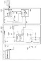
次に、図1を参照して、画像形成装置101を構成するエンジン部1001とコントローラ1003の構成について説明する。コントローラ1003は、ホストコンピュータ1006から画像情報を受信し、画像情報をエンジン部に送信する機能を有する。エンジン部1001は、画像形成部を制御して、コントローラから受信した画像情報に基づく画像形成を実行させる機能を有する。
Next, the configuration of the
エンジン部1001は低圧電源222を備え、低圧電源222は、エンジン制御CPU210を含むエンジン部1001およびコントローラ1003への電力を供給することが可能である。エンジン制御CPU210は、エンジン部1001の動作を制御する機能を有する。エンジン制御CPU210は、エンジン制御基板1002上に構成されており、低圧電源222とエンジン制御基板1002との間にはP型のMOSFET1004が設けられている。例えば、NORゲート1011、MOSFET1010は、第1制御回路として機能する。P型のMOSFET1004のゲート端子に接続されたユーザスイッチ1005がONされると、ゲート電圧がHighレベルからLowレベルへと遷移する。これにより、低圧電源222から各負荷(エンジン制御CPU210およびコントローラ1003)に対し電力供給が行われる構成となっている。
The
コントローラ1003は、コントローラメイン制御CPU1008(以下、単に「メイン制御CPU」ともいう)とコントローラサブ制御CPU1007(以下、単に「サブ制御CPU」ともいう)とを備えている。サブ制御CPU1007は、ホストコンピュータ1006とのインタフェース(I/F)機能と画像形成装置の通常の動作モード、省エネモードへの移行、省エネモードからの復帰など、動作状態を制御する省エネ制御機能を有する。ここで、動作状態には、通常の電力消費の動作モード、低消費電力の省エネモードへの移行、省エネモードから当該通常の電力消費の動作モードへの復帰が含まれる。
The
メイン制御CPU1008は、画像処理およびエンジン部1001との通信機能を有する。サブ制御CPU1007はメイン制御CPU1008への電力供給をコントロールするためのP型のMOSFET1009を制御し、省エネモード時にはメイン制御CPU1008への電力供給を遮断する。
The
図1においてユーザスイッチ1005がONされると、P型のMOSFET1004がONし、低圧電源222から3.3V(3.3VB)が、エンジン制御基板1002およびコントローラ1003のサブ制御CPU1007へ給電(電力供給)される。
In FIG. 1, when the
メイン制御CPU1008と3.3VBラインのON/OFFを制御するMOSFET1009のゲートはプルダウンされており、初期状態においてMOSFET1009は導通するよう構成されている。そのため、メイン制御CPU1008はユーザによりユーザスイッチ1005がONされた後から低圧電源222から電力が供給された状態となる。メイン制御CPU1008は、電力供給を受け、画像処理およびエンジン部1001との通信のため、初期化(イニシャライズ制御)を開始することが可能である。
The
メイン制御CPU1008の起動により、初期化が完了すると、メイン制御CPU1008は、エンジン部1001のエンジン制御CPU210と通信が可能な状態になる。
When initialization is completed by activation of the
サブ制御CPU1007の制御により画像形成装置が省エネモードに移行した場合に、メイン制御CPU1008は、エンジン制御CPU210の動作を停止させるために、NORゲート1011への出力信号を切り替える。また、サブ制御CPU1007の制御により画像形成装置が省エネモードから復帰した場合に、メイン制御CPU1008は、エンジン制御CPU210を起動させるために、NORゲート1011への出力信号を更に切り替える。
When the image forming apparatus shifts to the energy saving mode under the control of the
エンジン制御CPU210への電力供給ラインにはP型のMOSFET1010が配されている。P型のMOSFET1010のゲートには、エンジン制御CPU210と、メイン制御CPU1008とからの出力を入力とするNORゲート1011が接続されている。NORゲート1011はメイン制御CPU1008からの出力に基づき、エンジン制御CPU210のON/0FFを制御し、エンジン制御CPU210自身の出力によってP型のMOSFET1010のON状態を維持することが可能である。
A P-
さらに、P型のMOSFET1010のゲート端子は低圧電源からの3.3VB出力でプルアップされており、エンジン制御CPU210およびメイン制御CPU1008がOFFした際にP型のMOSFET1010の動作がOFFになるよう構成されている。P型のMOSFET1010のゲートにはPNPトランジスタ1012が配されており、PNPトランジスタ1012のベースにはコンデンサ1013の正極が接続されている。
Furthermore, the gate terminal of the P-
画像形成装置本体への電源投入直後においてコンデンサ1013の両端の電圧は、ほぼ0Vで低いことを利用し、画像形成装置の本体への電源投入直後、予め定められた時間、MOSFET1010を導通させエンジン部の起動時間の短縮化を実現する。
Immediately after the power supply to the image forming apparatus main body is turned on, the voltage across the
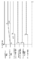
図4は、エンジン制御CPU210の起動制御を説明するタイミングチャートである。ユーザによりユーザスイッチ1005がONされると、P型のMOSFET1004がONし、3.3VBがエンジン制御基板1002およびコントローラ1003に供給される。電源投入直後にはコンデンサ1013には電荷が蓄積されていないため、コンデンサ1013の両端の電圧はほぼ0Vとなる。そのため、PNPトランジスタ1012のベース端子の電圧もほぼ0Vであり、エミッタ端子の電圧はベースエミッタ電圧(約0.6V)より高い電圧値となる。つまり、PNPトランジスタ1012のエミッタ端子に接続されているMOSFET1010のゲート電圧も約0.6Vとなる。一方、MOSFET1010のソース端子は3.3VBラインに接続されているので3.3Vである。よって、MOSFET1010のゲートソース間には電源投入直後に約2.7Vの電圧が加わることによりドレイン端子に導通し、MOSFET1010はONする(T1)。電源投入直後、コンデンサ1013の両端の電圧は、ほぼ0Vであり、画像形成装置の本体への電源投入直後、メイン制御CPU1008の起動とは独立に、MOSFET1010を導通させエンジン部の起動時間の短縮化を実現することができる。
FIG. 4 is a timing chart for explaining the startup control of the
MOSFET1010がONすると所定時間後にエンジン制御CPU210は起動し(T2)、エンジン制御CPU210は起動直後にポート1(P1)をHighにする(T3)。エンジン制御CPU210のポート1(P1)から出力されるHigh信号は、NORゲート1011に入力される。一方、メイン制御CPU1008が起動していない状態では、Low信号がNORゲート1011に入力された状態となる。この状態で、NORゲート1011の出力はHighからLow状態に切り替えられ、MOSFET1010のゲート端子電圧はLowの状態で維持される。
When the
MOSFET1010のゲート端子電圧をLowにした時点で、PNPトランジスタ1012のエミッタ端子はベース端子より電位が低くなりOFF状態になる。その後、コンデンサ1013の両端の電位は3.3Vまで上昇し(T5)、PNPトランジスタ1012のエミッタ端子は常にOFF状態を保持する。また、エンジン制御CPU210はポート2(P2)に接続されているコンデンサ1013の静電容量に基づく電圧値に従い、起動が画像形成装置の本体への電源投入によるものか、省エネモードからの復帰によるものかを判断する。
When the gate terminal voltage of the
電源投入時によるエンジン制御CPU210の起動であればコンデンサ1013の電圧値は3.3Vより十分低い電圧(例えば、0V)となる。また省エネモードからの復帰であればコンデンサ1013の電圧値は、ほぼ3.3Vである。エンジン制御CPU210は、コンデンサ1013の電圧値の検出結果に基づき、画像形成装置への電源投入時の起動か、省エネモードからの復帰による起動かを判別することができる。
If the
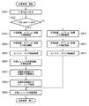
図5は、エンジン制御CPU210の起動制御の流れを説明するフローチャートである。エンジン制御CPU210が起動されると、S501で、エンジン制御CPU210は、ポート1(P1)の出力をHighにしてエンジン制御CPU210への電力供給をつかさどるMOSFET1010のONを維持する。
FIG. 5 is a flowchart for explaining the flow of startup control of the
その後、S502で、エンジン制御CPU210は、ポート2(P2)に接続されているコンデンサ1013の電位を検出する。そして、エンジン制御CPU210は、その検出結果に基づきエンジン制御CPU210の起動が画像形成装置の本体への電源投入によるものか、もしくは、省エネモードからの復帰によるものかを判断する。P2の電圧がLowレベルであった場合(S502−Yes)、処理はS503に進められ、エンジン制御CPU210は、画像形成装置への電源投入時の起動処理を実行する。エンジン制御CPU210は、電源投入による起動と判定した場合、メイン制御CPU1008の起動前に、第1制御回路(NORゲート1011、MOSFET1010)により電力の供給を受ける。エンジン制御CPU610は、起動後に以下のS503〜S509の処理を実行する。
Thereafter, in S502, the
尚、Lowレベルの判定は、例えば、電圧レベルの判定用の閾値を設定しておき、この閾値に対して、P2に入力される電圧が高ければ、コンデンサ1013の電圧値は、3.3Vの近傍のHighレベルの電圧と判定される。一方、閾値に対して、P2に入力される電圧が低ければ、コンデンサ1013の電圧は、3.3Vより十分低い、Lowレベルの電圧と判定される。
For the determination of the Low level, for example, a threshold value for determining the voltage level is set, and if the voltage input to P2 is higher than this threshold value, the voltage value of the
S503において、エンジン制御CPU210は、外部装置、オプション装置の接続確認を行い、S504で、外部装置、オプション装置との通信を開始する。そして、S505で、エンジン制御CPU210は、コントローラ1003との接続確認を行い、S506で、各部ユニットの有無確認、初期化処理を実行する。そして、S507で、エンジン制御CPU210は、画像形成装置内の記録材の有無検出し、S508で、画像形成装置内のクリーニング処理を行い、S509で、エンジン制御CPU210は、定着ユニットの加温制御を行う。
In S503, the
一方、S502の判定で、P2の電圧がLowレベルでない場合(S502−No)、処理はS510に進められ、エンジン制御CPU210は省エネモードから復帰するための起動処理を実行する。エンジン制御CPU210は、第2制御回路(NORゲート1011)を介して、メイン制御CPU1008の出力信号に基づき低圧電源222から電力の供給を受ける。エンジン制御CPU210は、起動後に以下のS510〜S512、S509の処理を実行する。
On the other hand, if it is determined in S502 that the voltage of P2 is not at the low level (S502-No), the process proceeds to S510, and the
まず、S510において、エンジン制御CPU210は、外部装置、オプション装置との接続確認し、S511において、外部装置、オプション装置との通信を開始する。S512において、エンジン制御CPU210は、コントローラとの接続確認を行い、S509で、エンジン制御CPU210は、定着ユニットの加温制御を行う。
First, in S510, the
本実施形態に拠れば、電源投入による起動か、省エネモードからの復帰による起動かを判定し、この判定結果に従い、エンジン制御CPUにおける起動処理の切り替えを制御することが可能になる。 According to the present embodiment, it is possible to determine whether the start-up is performed by turning on the power or the return from the energy-saving mode, and it is possible to control switching of the start-up process in the engine control CPU according to the determination result.
電源投入時の起動処理に比べて、省エネモードから復帰するための起動処理では、S506〜S508に対応する処理が実行されない。電源投入時の起動処理と比較して省エネモードからの復帰処理(起動に要する処理)を短縮化することで、省エネモードからの復帰の高速化を達成し、ユーザビリティーの向上を実現することができる。 In the startup process for returning from the energy saving mode, the processes corresponding to S506 to S508 are not executed as compared to the startup process at power-on. By shortening the return process from the energy saving mode (the process required for startup) compared to the startup process when the power is turned on, the speed of return from the energy saving mode can be increased, and usability can be improved. it can.
また電源投入時と省エネ復帰時において重複した処理を避けることは、装置の稼働時間を減らすため、装置寿命を延ばすという観点でも重要である。ここで装置とは、例えば、画像形成装置のコントローラのハードディスクドライブ、または、エンジン部のモータ類、ローラ、ベルト、感光ドラムユニット、現像剤などを含む。装置寿命の延命により低コストの画像形成装置を提供することができる。 In addition, avoiding duplicate processing at power-on and energy-saving return is also important from the viewpoint of extending the life of the apparatus in order to reduce the operation time of the apparatus. Here, the apparatus includes, for example, a hard disk drive of a controller of the image forming apparatus, motors of an engine unit, rollers, a belt, a photosensitive drum unit, a developer, and the like. By extending the life of the apparatus, a low-cost image forming apparatus can be provided.
<第2実施形態>
ユーザにより画像形成装置の電源のOFF/ONが繰り返された場合、第1実施形態の構成では、コンデンサ1013の電荷をOFF/ONが繰り返される短時間にディスチャージすることができない。そのため、エンジン制御CPUは、画像形成装置本体の電源投入時であるにもかかわらず省エネモードからの復帰と判断してしまう。本実施形態においては上記の場合を鑑みて、電源OFF時にエンジン制御CPU610によりコンデンサ1013の電荷をディスチャージする回路を備える構成を説明する。第1実施形態と同様の回路構成については、説明の重複を避けるため、説明を省略する。
Second Embodiment
When the power of the image forming apparatus is repeatedly turned off / on by the user, the configuration of the first embodiment cannot discharge the charge of the
図6は、第2実施形態にかかる画像形成装置を構成するエンジン部6001とコントローラ1003の構成を説明する図である。エンジン制御CPU610は、エンジン部6001の動作を制御する機能を有し、エンジン制御基板6002上に構成されている。低圧電源222とエンジン制御基板6002との間にはP型のMOSFET1004が設けられている。P型のMOSFET1004のゲート端子にはユーザスイッチ1005が接続されている。また、ユーザスイッチ1005のOFF/ONに連動し、ユーザスイッチ1005の状態をエンジン制御CPU610のポート3(P3)に入力することが可能な検出用スイッチ1015が設けられている。エンジン制御CPU610は、ポート3(P3)に入力される検出用スイッチ1015の信号に基づき、ユーザスイッチ1005のOFF/ONの状態を検出することができる。
FIG. 6 is a diagram illustrating the configuration of the
また、エンジン制御CPU610は、MOSFET1004のゲートに接続するポート4(P4)を介して、MOSFET1004のON状態を保持するための制御信号(制御情報)を出力することが可能である。ユーザスイッチ1005がOFFにされてもMOSFET1004のON状態を保持することが可能である。
Further, the
更に、ユーザスイッチ1005がOFFの時にコンデンサ1013をディスチャージ(放電)するためにNPNトランジスタ1014がエンジン制御基板6002に設けられている。NPNトランジスタ1014のベース端子には検出用スイッチ1015が接続されている。ユーザスイッチ1005のOFFの時に検出用スイッチ1015がOFFになると、NPNトランジスタ1014は、抵抗1016を介しベース電流が流れ容量性素子(コンデンサ)1013の両端をディスチャージする。コンデンサ1013、NPNトランジスタ1014、エンジン制御CPU910の起動時に、電源投入による起動か、省エネモードから通常の電力消費の動作モードへの復帰による起動かを判定するための判定回路として機能する。
Further, an
図7は、エンジン制御CPU610の起動制御の流れを説明するフローチャートである。エンジン制御CPU610が起動されると、S701で、エンジン制御CPU610は、ポート1(P1)の出力をHighにしてエンジン制御CPU610への電力供給をつかさどるMOSFET1010のONを維持する。
FIG. 7 is a flowchart for explaining the flow of start control of the
その後、S702で、エンジン制御CPU610は、検出用スイッチ1015から入力される信号に基づき、ポート4(P4)の出力をHighにする。エンジン制御CPU610は、ユーザによりユーザスイッチ1005がOFFにされてもエンジン制御基板6002およびコントローラ1003への電力供給が切断されないように制御する。
Thereafter, in S702, the
続いて、S703で、エンジン制御CPU610は、ポート2(P2)に接続されているコンデンサ1013の電位(コンデンサ1013に蓄えられている電荷)を検出する。そして、エンジン制御CPU610は、その検出結果に基づきエンジン制御CPU610の起動が画像形成装置の本体への電源投入によるものか、もしくは、省エネモードからの復帰によるものかを判断する。P2の電圧(電荷)がLowレベルであった場合(S703−Yes)、処理はS704に進められ、エンジン制御CPU610は、画像形成装置への電源投入時の起動処理を実行する。エンジン制御CPU610は、電源投入による起動と判定した場合、メイン制御CPU1008の起動前に、第1制御回路(NORゲート1011、MOSFET1010)により電力の供給を受ける。エンジン制御CPU610は、起動後に以下のS704〜S710の処理を実行する。
Subsequently, in S703, the
S704において、エンジン制御CPU610は、外部装置、オプション装置との接続確認を行い、S705で、外部装置、オプション装置との通信を開始する。そして、S706で、エンジン制御CPU610は、コントローラ1003との接続確認を行い、S707で、各部ユニットの有無確認、初期化処理を実行する。そして、S708で、エンジン制御CPU610は、画像形成装置内の記録材の有無検出し、S709で、画像形成装置内のクリーニング処理を行い、S710で、エンジン制御CPU610は、定着ユニットの加温制御を行う。
In S704, the
一方、S703の判定で、P2の電圧がLowレベルでない場合(S703−No)、処理はS711に進められ、エンジン制御CPU610は省エネモードから復帰するための起動処理を実行する。エンジン制御CPU610は、第2制御回路(NORゲート1011)を介して、メイン制御CPU1008の出力信号に基づき低圧電源222から電力の供給を受ける。エンジン制御CPU610は、起動後に以下のS711〜S713、S710の処理を実行する。
On the other hand, if it is determined in S703 that the voltage of P2 is not at the low level (S703-No), the process proceeds to S711, and the
まず、S711において、エンジン制御CPU610は、外部装置、オプション装置との接続確認し、S712において、外部装置、オプション装置との通信を開始する。S713において、エンジン制御CPU610は、コントローラとの接続確認を行い、S710で、エンジン制御CPU610は、定着ユニットの加温制御を行う。
First, in S711, the
ユーザスイッチ1005がOFFされてもMOSFET1004がOFFされないように、エンジン制御CPU610は、P型のMOSFET1004のON状態を保持するための制御信号を出力することが可能である。
The
次に、図8を参照して、エンジン制御CPU610の電源OFF時の制御について説明する。まず、S801において、エンジン制御CPU610は、ポート3(P3)の入力信号に基づき、ユーザスイッチ1005がOFFされたことを検知した場合(S801−Yes)、処理は、S802に進められる。一方、ユーザスイッチ1005がOFFされたことが検知されない場合(S801−No)、待機状態となる。
Next, the control of the
S802において、エンジン制御CPU610は、コントローラ1003のメイン制御CPU1008へユーザスイッチ1005がOFFされたことを通知する。S803において、エンジン制御CPU610は、画像形成を実行する各ユニットの終了処理を行い、コントローラ1003のメイン制御CPU1008から送信されるOFF許可信号の受信待ちの状態で待機する(S804―No)。メイン制御CPU1008から送信されるOFF許可信号をエンジン制御CPU610が受信した時点で(S804−Yes)、エンジン制御CPU610は、ポート4(P4)の出力信号をHighにして、MOSFET1004の動作状態をOFFにする。
In step S802, the
なお、ユーザスイッチ1005と連動した検出用スイッチ1015はユーザによりユーザスイッチ1005がOFFにされた時点でオープン状態となる。検出用スイッチ1015がオープン状態になると、NPNトランジスタ1014にベース電流が流れNPNトランジスタ1014がONの状態になり、コンデンサ1013をディスチャージする。
Note that the
ユーザスイッチ1005が短時間にOFF/ONされた場合でも、電源投入による起動か、省エネモードからの復帰による起動かを判定し、この判定結果に従いエンジン制御CPUにおける起動処理の切り替えを制御することが可能になる。
Even when the
電源投入時のエンジン制御CPU610の起動をコントローラ1003のメイン制御CPU1008からの指示を待つことなく起動することが可能となり、画像形成装置の電源投入からの起動処理の短縮化を図ることが可能になる。
It is possible to start the
<第3実施形態>
次に、電源投入による起動か、低消費電力の省エネモードから通常の電力消費の動作モードへの復帰による起動かを判定するための判定回路の構成をラッチ回路により構成した第3実施形態を説明する。図9は、第3実施形態にかかる画像形成装置を構成するエンジン部9001とコントローラ1003の構成を説明する図である。エンジン制御CPU910は、エンジン部9001の動作を制御する機能を有し、エンジン制御基板9002上に構成されている。ラッチ回路としてPNPトランジスタ1017とNPNトランジスタ1019によりサイリスタ回路を構成している。サイリスタ回路は、エンジン制御CPU910の起動時に、電源投入による起動か、省エネモードから通常の電力消費の動作モードへの復帰による起動か、を判定するための判定回路として機能する。
<Third Embodiment>
Next, a description will be given of a third embodiment in which the configuration of a determination circuit for determining whether the activation is performed by turning on the power or the activation is performed by returning from the low power consumption energy saving mode to the normal power consumption operation mode by a latch circuit. To do. FIG. 9 is a diagram illustrating the configuration of the
サイリスタ回路はエンジン制御CPU910のポート2(P2)と接続し、検出用スイッチ1015による電源のONの検知結果に従い、電源がONの状態を識別するための出力信号のレベル(High)の状態を保持する。一度、Highが保持されると、サイリスタ回路はHighの状態を保持し、エンジン制御CPU910へのポート5(P5)の信号レベルはHighの状態に保持(ラッチ)される。また、サイリスタ回路において、Highの状態に保持されている信号は、検出用スイッチ1015による電源のOFFの検知結果に従い解除されてサイリスタ回路の出力はLowレベルになる。
The thyristor circuit is connected to port 2 (P2) of the
画像形成装置本体への電源投入時において、サイリスタ回路はHighの状態にラッチされていないのでポート5(P5)への信号レベルはLowになる。また、サイリスタ回路を構成しているNPNトランジスタ1019のベース電位は、サイリスタ回路がHighの状態にラッチされていない電源投入時においてLowレベルとなっている。NPNトランジスタ1019のエミッタ端子に対しダイオード1020を介してMOSFET1010のゲートを接続する。これにより、電源投入時にMOSFET1010のゲート電位をソース電位(3.3V)に対し引き下げることが可能となりMOSFET1010をONできる。このことは電源投入時においてコントローラ1003からの指示を待たずにエンジン制御CPU910をONすることを可能にする。また、ダイオード1020はサイリスタ回路がラッチした後にもNORゲート1011の出力としてMOSFET1010のゲートレベルをLowに維持することを可能にする。また、ユーザによってON/OFFされるユーザスイッチ1005と連動してON/OFFする検出用スイッチ1015とNPNトランジスタ1018のベース端子とを接続する。ユーザスイッチ1005がOFFにされて検出用スイッチ1015がオープンになると、NPNトランジスタ1018にベース電流が流れラッチ回路をリセットするよう構成されている。これによりユーザによりユーザスイッチ1005のOFF/ONが短時間で繰り返されたとしても、ラッチしたまま本体への電源投入が行われることがなくなり正常なエンジン起動制御が実現可能となる。
When the power supply to the image forming apparatus main body is turned on, since the thyristor circuit is not latched in the High state, the signal level to the port 5 (P5) becomes Low. The base potential of the
図10は、エンジン制御CPU910の起動制御の流れを説明するフローチャートとである。エンジン制御CPU910が起動されると、S1001で、エンジン制御CPU910は、ポート1(P1)の出力をHighにしてエンジン制御CPU910への電力供給をつかさどるMOSFET1010のONを維持する。
FIG. 10 is a flowchart for explaining the flow of startup control of the
その後、S1002で、エンジン制御CPU910は、検出用スイッチ1015から入力される信号に基づき、ポート4(P4)をHigh(Low)にする。エンジン制御CPU910は、ユーザによりユーザスイッチ1005がOFFにされてもエンジン制御基板9002およびコントローラ1003への電力供給が切断されないよう制御する。
Thereafter, in S1002, the
続いて、S1003で、エンジン制御CPU910は、ポート5(P5)に接続されているラッチ回路の出力の電位を読み取る。エンジン制御CPU910は、ラッチ回路から出力される電位に基づき、画像形成装置本体への電源投入による起動か、もしくは、省エネモードからの復帰による起動であるかを判断する。
Subsequently, in S1003, the
ポート5(P5)の電圧がLowレベルであった場合、エンジン制御CPU910は、本体への電源投入による起動であると判断し(S1003−Yes)、処理はS1004に進められる。エンジン制御CPU910は、電源投入による起動と判定した場合、メイン制御CPU1008の起動前に、第1制御回路(NORゲート1011、MOSFET1010)により電力の供給を受ける。エンジン制御CPU910は、画像形成装置への電源投入時の起動処理として、以下のS1004〜S1011の処理を実行する。
When the voltage of the port 5 (P5) is at the low level, the
S1004において、エンジン制御CPU910は、ポート2(P2)をHighに設定し、ラッチ回路をラッチさせる。
In S1004, the
S1005において、エンジン制御CPU910は、外部装置、オプション装置との接続確認を行い、S1006で、外部装置、オプション装置との通信を開始する。そして、S1007で、エンジン制御CPU910は、コントローラ1003との接続確認を行い、S1008で、各部ユニットの有無確認、初期化処理を実行する。そして、S1009で、エンジン制御CPU910は、画像形成装置内の記録材の有無検出し、S1010で、画像形成装置内のクリーニング処理を行い、S1011で、エンジン制御CPU910は、定着ユニットの加温制御を行う。
In S1005, the
一方、S1003の判定において、ラッチ回路がHigh信号をラッチした状態でありポート5(P5)への入力がHighである場合、エンジン制御CPU910は、省エネモードからの復帰であると判定する。エンジン制御CPU910は、第2制御回路(NORゲート1011)を介して、メイン制御CPU1008の出力信号に基づき低圧電源222から電力の供給を受ける。エンジン制御CPU910は省エネモードから復帰するための起動処理として、以下のS1012〜S1014、S1011の処理を実行する。
On the other hand, in the determination of S1003, when the latch circuit is in a state of latching the High signal and the input to the port 5 (P5) is High, the
まず、S1012において、エンジン制御CPU910は、外部装置、オプション装置との接続確認し、S1013において、外部装置、オプション装置との通信を開始する。S1014において、エンジン制御CPU910は、コントローラとの接続確認を行い、S1011で、エンジン制御CPU910は、定着ユニットの加温制御を行う。
First, in S1012, the
次に、図11を参照して、エンジン制御CPU910の電源OFF時の制御について説明する。まず、S1101において、エンジン制御CPU910は、ポート3(P3)の入力信号に基づき、ユーザスイッチ1005がOFFされたことを検知した場合(S1101−Yes)、処理は、S1102に進められる。一方、ユーザスイッチ1005がOFFされたことが検知されない場合(S1101−No)、待機状態となる。
Next, the control of the
S1102において、エンジン制御CPU910は、コントローラ1003のメイン制御CPU1008へユーザスイッチ1005がOFFされたことを通知する。S1103において、エンジン制御CPU910は、画像形成を実行する各ユニットの終了処理を行い、コントローラ1003のメイン制御CPU1008から送信されるOFF許可信号の受信待ちの状態で待機する(S1104―No)。メイン制御CPU1008から送信されるOFF許可信号をエンジン制御CPU910が受信した時点で(S1104−Yes)、エンジン制御CPU910は、ポート4(P4)の出力信号をHighにして、MOSFET1004の動作状態をOFFにする。
In step S1102, the
なお、ユーザスイッチ1005と連動した検出用スイッチ1015はユーザによりユーザスイッチ1005がOFFにされた時点でオープン状態となる。検出用スイッチ1015がオープン状態になると、NPNトランジスタ1018にベース電流が流れNPNトランジスタ1018がONし、ラッチ回路はリセットされる。
Note that the
本実施形態によれば、電源投入による起動か、省エネモードからの復帰による起動かを判定し、この判定結果に従いエンジン制御CPUにおける起動処理の切り替えを制御することが可能になる。 According to the present embodiment, it is possible to determine whether the start-up is performed by turning on the power or the return from the energy saving mode, and switching of the start-up process in the engine control CPU can be controlled according to the determination result.
電源投入時のエンジン制御CPU910の起動をコントローラ1003のメイン制御CPU1008からの指示を待つことなく起動することが可能となり、画像形成装置の電源投入からの起動処理の短縮化を図ることが可能になる。
It is possible to start the
101 画像形成装置
210 エンジン制御CPU
222 低圧電源
1003 コントローラ
1006 ホストコンピュータ
1007 コントローラサブ制御CPU
1008 コントローラメイン制御CPU
101
222 Low-
1008 Controller main control CPU
Claims (5)
前記コントローラは、
前記ホストコンピュータとの通信と、当該画像形成装置の動作モードの切り替えと、を制御するサブ制御手段と、
前記サブ制御手段による前記動作モードの切り替えに従い、前記エンジン部の動作を制御するメイン制御手段と、を備え
前記エンジン部は、
前記画像形成手段の動作を制御するエンジン制御手段と、
電源が投入され、前記コントローラに電力が供給された際、前記コントローラへの電力供給とは独立に、前記電源から前記エンジン制御手段に電力を供給する第1制御回路と、
通常の電力消費の動作モードから低消費電力の省エネモードへの移行時、前記メイン制御手段から出力される出力信号によって、前記電源から前記エンジン制御手段に供給される電力をオフにし、前記省エネモードから前記通常の電力消費の動作モードへの移行時、前記メイン制御手段から出力される出力信号によって、前記電源から前記エンジン制御手段に供給される電力をオンにする第2制御回路と、
前記エンジン制御手段の起動が、電源投入による起動か、前記省エネモードから前記通常の電力消費の動作モードへの復帰による起動か、を判定するための判定回路と、を備え、
前記エンジン制御手段は、前記判定回路が電源投入による起動を示している場合、第1の起動処理を実行し、前記判定回路が前記通常の電力消費の動作モードへの復帰による起動を示している場合、前記第1の起動処理より処理時間の短い第2の起動処理を実行し、
前記判定回路は、前記電源がオフにされると当該判定回路を構成する容量性素子の電荷が放電されるように構成され、前記電源がオンの状態で、前記容量性素子には電荷が蓄えられる様に構成されていることを特徴とする画像形成装置。 An image forming apparatus comprising: a controller that receives image information from a host computer and transmits the image information to an engine unit; and an engine unit that causes an image forming unit to perform image formation based on the image information received from the controller. There,
The controller is
Sub-control means for controlling communication with the host computer and switching of the operation mode of the image forming apparatus;
Main control means for controlling the operation of the engine unit in accordance with the switching of the operation mode by the sub-control means, the engine unit,
Engine control means for controlling the operation of the image forming means;
Power is turned on and when the power is supplied to the controller, independently of the power supply to the controller, a first control circuit for supplying electric power to the engine control unit from said power source,
When shifting from the normal power consumption operation mode to the low power consumption energy saving mode, the power supplied from the power source to the engine control means is turned off by the output signal output from the main control means , and the energy saving mode is set. A second control circuit for turning on the power supplied from the power source to the engine control means by an output signal output from the main control means at the time of transition to the normal power consumption operation mode ;
Starting the engine control unit, or power is turned on for startup, and a determination circuit for determining a start or, by a return to the operation mode of the normal power consumption from the power saving mode,
The engine control means executes a first activation process when the determination circuit indicates activation upon power-on, and the determination circuit indicates activation upon return to the normal power consumption operation mode. A second startup process having a processing time shorter than that of the first startup process,
The determination circuit is configured such that when the power is turned off, the charge of the capacitive element constituting the determination circuit is discharged, and the charge is stored in the capacitive element when the power is on. An image forming apparatus configured as described above .
前記サブ制御手段の制御により前記画像形成装置が前記省エネモードから前記通常の電力消費の動作モードへ復帰した場合に、前記メイン制御手段は、前記第2制御回路に前記エンジン制御手段への電力供給をオンにするための信号を出力することを特徴とする請求項1に記載の画像形成装置。 When the image forming apparatus shifts from the normal power consumption operation mode to the energy saving mode under the control of the sub control unit, the main control unit supplies power to the engine control unit to the second control circuit. Outputs a signal to turn off ,
When the image forming apparatus returns from the energy saving mode to the normal power consumption operation mode by the control of the sub control unit, the main control unit supplies power to the engine control unit to the second control circuit. the image forming apparatus according to claim 1, characterized in that the output be because of the signal to turn on.
前記コントローラは、
前記ホストコンピュータとの通信と、当該画像形成装置の動作モードの切り替えと、を制御するサブ制御手段と、
前記サブ制御手段による前記動作モードの切り替えに従い、前記エンジン部の動作を制御するメイン制御手段と、を備え、
前記エンジン部は、
前記画像形成手段の動作を制御するエンジン制御手段と、
電源が投入され、前記コントローラに電力が供給された際、前記コントローラへの電力供給とは独立に、前記電源から前記エンジン制御手段に電力を供給する第1制御回路と、
通常の電力消費の動作モードから低消費電力の省エネモードへの移行時、前記メイン制御手段から出力される出力信号によって、前記電源から前記エンジン制御手段に供給される電力をオフにし、前記省エネモードから前記通常の電力消費の動作モードへの移行時、前記メイン制御手段から出力される出力信号によって、前記電源から前記エンジン制御手段に供給される電力をオンにする第2制御回路と、
前記エンジン制御手段の起動が、電源投入による起動か、前記省エネモードから前記通常の電力消費の動作モードへの復帰による起動か、を判定するための判定回路と、を備え、
前記エンジン制御手段は、前記判定回路が電源投入による起動を示している場合、第1の起動処理を実行し、前記判定回路が前記通常の電力消費の動作モードへの復帰による起動を示している場合、前記第1の起動処理より処理時間の短い第2の起動処理を実行し、
前記判定回路は、前記電源がオフのときには第1の電位を出力し、前記電源がオンとなった後に第2の電位を出力するラッチ回路を含み、
電源投入時、前記ラッチ回路が出力する前記第1の電位により、前記第1制御回路は、前記電源から前記エンジン制御手段への電力の供給をオンにすることを特徴とする画像形成装置。 An image forming apparatus comprising: a controller that receives image information from a host computer and transmits the image information to an engine unit; and an engine unit that causes an image forming unit to perform image formation based on the image information received from the controller. There,
The controller is
Sub-control means for controlling communication with the host computer and switching of the operation mode of the image forming apparatus;
Main control means for controlling the operation of the engine unit in accordance with the switching of the operation mode by the sub-control means,
The engine part is
Engine control means for controlling the operation of the image forming means;
A first control circuit for supplying power from the power source to the engine control means independently of power supply to the controller when power is turned on and power is supplied to the controller;
When shifting from the normal power consumption operation mode to the low power consumption energy saving mode, the power supplied from the power source to the engine control means is turned off by the output signal output from the main control means, and the energy saving mode is set. A second control circuit for turning on the power supplied from the power source to the engine control means by an output signal output from the main control means at the time of transition to the normal power consumption operation mode;
A determination circuit for determining whether activation of the engine control means is activation by power-on or activation by returning from the energy saving mode to the normal power consumption operation mode;
The engine control means executes a first activation process when the determination circuit indicates activation upon power-on, and the determination circuit indicates activation upon return to the normal power consumption operation mode. A second startup process having a processing time shorter than that of the first startup process,
The determination circuit includes a latch circuit that outputs a first potential when the power source is off, and outputs a second potential after the power source is on,
When power is turned on by the first potential the latch circuit outputs, said first control circuit includes images forming device you wherein turning on the power supply of to the engine control unit from the power supply .
Priority Applications (1)
| Application Number | Priority Date | Filing Date | Title |
|---|---|---|---|
| JP2007248181A JP5100280B2 (en) | 2007-09-25 | 2007-09-25 | Image forming apparatus |
Applications Claiming Priority (1)
| Application Number | Priority Date | Filing Date | Title |
|---|---|---|---|
| JP2007248181A JP5100280B2 (en) | 2007-09-25 | 2007-09-25 | Image forming apparatus |
Publications (3)
| Publication Number | Publication Date |
|---|---|
| JP2009080211A JP2009080211A (en) | 2009-04-16 |
| JP2009080211A5 JP2009080211A5 (en) | 2010-11-11 |
| JP5100280B2 true JP5100280B2 (en) | 2012-12-19 |
Family
ID=40655010
Family Applications (1)
| Application Number | Title | Priority Date | Filing Date |
|---|---|---|---|
| JP2007248181A Expired - Fee Related JP5100280B2 (en) | 2007-09-25 | 2007-09-25 | Image forming apparatus |
Country Status (1)
| Country | Link |
|---|---|
| JP (1) | JP5100280B2 (en) |
Families Citing this family (2)
| Publication number | Priority date | Publication date | Assignee | Title |
|---|---|---|---|---|
| JP5421209B2 (en) * | 2010-08-27 | 2014-02-19 | 株式会社沖データ | Power supply control circuit and image forming apparatus having power supply control circuit |
| JP2013035153A (en) * | 2011-08-04 | 2013-02-21 | Ricoh Co Ltd | Image forming apparatus, image forming method, and image forming program |
Family Cites Families (11)
| Publication number | Priority date | Publication date | Assignee | Title |
|---|---|---|---|---|
| JP3651758B2 (en) * | 1998-12-25 | 2005-05-25 | 株式会社リコー | Energy saving return method and recording device using the same |
| JP2000307750A (en) * | 1999-04-22 | 2000-11-02 | Canon Inc | Communication apparatus, reception device and transmission device |
| JP2001180083A (en) * | 1999-12-24 | 2001-07-03 | Fuji Xerox Co Ltd | Printer |
| JP3839241B2 (en) * | 2000-03-30 | 2006-11-01 | 株式会社リコー | Image forming apparatus management system, image forming apparatus used therefor, and power supply control method therefor |
| JP2003186357A (en) * | 2001-12-20 | 2003-07-04 | Copyer Co Ltd | Method for returning from energy saving and image forming apparatus |
| JP2004148569A (en) * | 2002-10-29 | 2004-05-27 | Ricoh Co Ltd | Image forming apparatus |
| JP4446790B2 (en) * | 2004-04-27 | 2010-04-07 | 京セラミタ株式会社 | Image forming apparatus |
| JP4631385B2 (en) * | 2004-10-14 | 2011-02-16 | 富士ゼロックス株式会社 | Controller, image forming apparatus, and power supply control method |
| JP2006301367A (en) * | 2005-04-21 | 2006-11-02 | Konica Minolta Business Technologies Inc | Image forming apparatus |
| JP2007047211A (en) * | 2005-08-05 | 2007-02-22 | Ricoh Co Ltd | Fixing heater controller, fixing heater control method, and image forming apparatus |
| JP4459150B2 (en) * | 2005-10-07 | 2010-04-28 | キヤノン株式会社 | Printing apparatus and control method thereof |
-
2007
- 2007-09-25 JP JP2007248181A patent/JP5100280B2/en not_active Expired - Fee Related
Also Published As
| Publication number | Publication date |
|---|---|
| JP2009080211A (en) | 2009-04-16 |
Similar Documents
| Publication | Publication Date | Title |
|---|---|---|
| JP4480470B2 (en) | Image forming apparatus and image forming method | |
| KR101669443B1 (en) | Image forming apparatus capable of shortening time required for start-up, control method therefor, and storage medium | |
| JP2011112710A (en) | Image forming apparatus | |
| US20200329166A1 (en) | Image forming apparatus and controlling method for the same | |
| JP5978835B2 (en) | Image processing device | |
| JP2008158210A (en) | Power source supply control apparatus, power source supply control method and image forming apparatus | |
| US20110273742A1 (en) | Electronic apparatus, image forming apparatus, and computer program product | |
| JP5489625B2 (en) | Image forming apparatus | |
| JP2012230228A (en) | Image forming apparatus | |
| JP5100280B2 (en) | Image forming apparatus | |
| JP2017219771A (en) | Image forming apparatus | |
| JP2006129651A (en) | Power supply, system equipment, electronic equipment, and power supply control method | |
| JP2017027458A (en) | Memory control device and image forming apparatus having the same | |
| JP2006142779A (en) | Electric power source starting method and device to which the method is applied | |
| JP2010026037A (en) | Image forming apparatus | |
| JP2006234970A (en) | Image forming apparatus and control method therefor, and control program | |
| JP7318528B2 (en) | Power supply circuit and electronic equipment with power supply circuit | |
| JP2005115478A (en) | Control system | |
| JP4423070B2 (en) | Image forming apparatus and power saving control method thereof | |
| JP2000324820A (en) | Power supply, image-forming device, image-forming system, method for controlling the power supply, power supply control method of the image-forming device, and storage medium | |
| JP5247098B2 (en) | Image forming apparatus and control method thereof | |
| JP2006010825A (en) | Image forming device | |
| JP7158948B2 (en) | image forming device | |
| JP2007021844A (en) | Printer | |
| JP7119629B2 (en) | POWER SUPPLY DEVICE, CONTROL METHOD OF POWER SUPPLY DEVICE, IMAGE FORMING APPARATUS |
Legal Events
| Date | Code | Title | Description |
|---|---|---|---|
| A521 | Written amendment |
Free format text: JAPANESE INTERMEDIATE CODE: A523 Effective date: 20100927 |
|
| A621 | Written request for application examination |
Free format text: JAPANESE INTERMEDIATE CODE: A621 Effective date: 20100927 |
|
| A977 | Report on retrieval |
Free format text: JAPANESE INTERMEDIATE CODE: A971007 Effective date: 20120606 |
|
| A131 | Notification of reasons for refusal |
Free format text: JAPANESE INTERMEDIATE CODE: A131 Effective date: 20120611 |
|
| A521 | Written amendment |
Free format text: JAPANESE INTERMEDIATE CODE: A523 Effective date: 20120808 |
|
| TRDD | Decision of grant or rejection written | ||
| A01 | Written decision to grant a patent or to grant a registration (utility model) |
Free format text: JAPANESE INTERMEDIATE CODE: A01 Effective date: 20120827 |
|
| A01 | Written decision to grant a patent or to grant a registration (utility model) |
Free format text: JAPANESE INTERMEDIATE CODE: A01 |
|
| A61 | First payment of annual fees (during grant procedure) |
Free format text: JAPANESE INTERMEDIATE CODE: A61 Effective date: 20120925 |
|
| FPAY | Renewal fee payment (event date is renewal date of database) |
Free format text: PAYMENT UNTIL: 20151005 Year of fee payment: 3 |
|
| R151 | Written notification of patent or utility model registration |
Ref document number: 5100280 Country of ref document: JP Free format text: JAPANESE INTERMEDIATE CODE: R151 |
|
| FPAY | Renewal fee payment (event date is renewal date of database) |
Free format text: PAYMENT UNTIL: 20151005 Year of fee payment: 3 |
|
| LAPS | Cancellation because of no payment of annual fees |