JP5091601B2 - Sequin feeder and sewing machine capable of sequin sewing - Google Patents

Sequin feeder and sewing machine capable of sequin sewing Download PDF

Info

Publication number
JP5091601B2
JP5091601B2 JP2007244083A JP2007244083A JP5091601B2 JP 5091601 B2 JP5091601 B2 JP 5091601B2 JP 2007244083 A JP2007244083 A JP 2007244083A JP 2007244083 A JP2007244083 A JP 2007244083A JP 5091601 B2 JP5091601 B2 JP 5091601B2
Authority
JP
Japan
Prior art keywords
sequin
feed
sewing
sequin feed
unit
Prior art date
Legal status (The legal status is an assumption and is not a legal conclusion. Google has not performed a legal analysis and makes no representation as to the accuracy of the status listed.)
Expired - Fee Related
Application number
JP2007244083A
Other languages
Japanese (ja)
Other versions
JP2008114049A5 (en
JP2008114049A (en
Inventor
愛介 村瀬
Current Assignee (The listed assignees may be inaccurate. Google has not performed a legal analysis and makes no representation or warranty as to the accuracy of the list.)
Tokai Kogyo Sewing Machine Co Ltd
Original Assignee
Tokai Kogyo Sewing Machine Co Ltd
Priority date (The priority date is an assumption and is not a legal conclusion. Google has not performed a legal analysis and makes no representation as to the accuracy of the date listed.)
Filing date
Publication date
Application filed by Tokai Kogyo Sewing Machine Co Ltd filed Critical Tokai Kogyo Sewing Machine Co Ltd
Priority to JP2007244083A priority Critical patent/JP5091601B2/en
Priority to CN2007101545547A priority patent/CN101161900B/en
Priority to DE102007048344A priority patent/DE102007048344A1/en
Priority to US11/870,703 priority patent/US20080087206A1/en
Priority to KR1020070103105A priority patent/KR100925588B1/en
Priority to TR2007/07023A priority patent/TR200707023A2/en
Priority to GR20080100114A priority patent/GR20080100114A/en
Priority to BRPI0801112-5A priority patent/BRPI0801112A2/en
Priority to ITMI20080577 priority patent/ITMI20080577A1/en
Publication of JP2008114049A publication Critical patent/JP2008114049A/en
Publication of JP2008114049A5 publication Critical patent/JP2008114049A5/ja
Application granted granted Critical
Publication of JP5091601B2 publication Critical patent/JP5091601B2/en
Expired - Fee Related legal-status Critical Current
Anticipated expiration legal-status Critical

Links

Images

Classifications

    • DTEXTILES; PAPER
    • D05SEWING; EMBROIDERING; TUFTING
    • D05BSEWING
    • D05B3/00Sewing apparatus or machines with mechanism for lateral movement of the needle or the work or both for making ornamental pattern seams, for sewing buttonholes, for reinforcing openings, or for fastening articles, e.g. buttons, by sewing
    • D05B3/12Sewing apparatus or machines with mechanism for lateral movement of the needle or the work or both for making ornamental pattern seams, for sewing buttonholes, for reinforcing openings, or for fastening articles, e.g. buttons, by sewing for fastening articles by sewing
    • DTEXTILES; PAPER
    • D05SEWING; EMBROIDERING; TUFTING
    • D05BSEWING
    • D05B35/00Work-feeding or -handling elements not otherwise provided for
    • D05B35/06Work-feeding or -handling elements not otherwise provided for for attaching bands, ribbons, strips, or tapes or for binding
    • DTEXTILES; PAPER
    • D05SEWING; EMBROIDERING; TUFTING
    • D05CEMBROIDERING; TUFTING
    • D05C7/00Special-purpose or automatic embroidering machines
    • D05C7/08Special-purpose or automatic embroidering machines for attaching cords, tapes, bands, or the like

Description

本発明は、シークイン連結体からシークインを切断しつつ該シークインを被縫製体に縫着するミシンにおけるシークイン送り装置に関し、特に、縫い付けるシークインを縫いの途中で切替えることが可能なシークイン送り装置に関する。更には、異なるピッチのシークインを組み合わせて縫い付けるのに適したミシンに関する。   The present invention relates to a sequin feed device in a sewing machine that sews a sequin to a sewing object while cutting the sequin from a sequin coupling body, and more particularly to a sequin feed device that can switch sequins to be sewn during sewing. Furthermore, the present invention relates to a sewing machine suitable for sewing sequins having different pitches in combination.

従来のシークイン送り装置としては、例えば、下記特許文献1あるいは特許文献2又は3に示されたものが知られている。このようなシークイン送り装置は、多数のシークイン(スパンコール)を連結してなるシークイン連結体を巻回収納したリールから該シークイン連結体を繰り出して支承板の上面に載置し、送りレバーの前進及び後退動作によってシークイン連結体を1個分のシークインのサイズに対応する所定ピッチで送り出す送り機構を備え、ミシンの針棒の縫い動作に連動して送り出されたシークイン連結体から1個のシークインを切断しつつシークインを被縫製体に縫着するようになっている。
ドイツ実用新案登録第G9209764.2号公報 米国特許第5755168号公報 ドイツ特許第DE19538084号公報(特許文献2に対応)
As conventional sequin feeders, for example, those shown in Patent Document 1 or Patent Document 2 or 3 below are known. Such a sequin feeding device is configured to feed out the sequin coupling body from a reel in which a sequin coupling body formed by connecting a large number of sequins (sequins) is wound and placed on the upper surface of the support plate. Equipped with a feed mechanism that feeds the sequined linked body at a predetermined pitch corresponding to the size of one sequin by reverse movement, cutting one sequin from the sequined linked body fed in conjunction with the sewing operation of the needle bar of the sewing machine However, sequins are sewn on the workpiece.
German utility model registration No. G9209764.2 US Pat. No. 5,755,168 German patent DE19538084 (corresponding to Patent Document 2)

また、下記特許文献4においては、シークイン送り装置を刺繍ミシンの縫いヘッドに装着することで、刺繍布等の被刺繍物にシークインを縫い付けることができるようにした刺繍ミシンが示されている。
特開2004-167097号公報
Further, Patent Document 4 below discloses an embroidery sewing machine in which a sequin feeder can be sewn to an embroidery object such as an embroidery cloth by attaching a sequin feeding device to a sewing head of the embroidery sewing machine.
Japanese Patent Laid-Open No. 2004-167097

一方、下記特許文献5及び6においては、縫いの途中でシークインを切替えながら縫い付けることができるようにした装置が示されている。この従来装置では、それぞれ所定の形及び色のシークインが連結されたシークイン連結体を巻回した二つのシークインリールと、これらから繰り出したシークイン連結体を針元に向かって個別に送り出すための個別の送り棒とが備えられており、送り棒による送り動作を制御信号に基づいて選択することで、送り出すシークイン連結体を切替えながら連続的にシークイン縫いを行なうことができる。しかし、シークイン連結体からシークインを切断するためのカッターは、共通のものが1つしか設けられておらず、2つのシークイン連結体のうち送り出された方のシークイン連結体のシークインを該共通のカッターで切断する構成からなっている。そのため、2つのシークイン連結体におけるシークインのサイズは互いに異ならせることができるが、一旦それぞれ所定のサイズのシークインをセットするように装置を構成すると、もうサイズの自由な変更ができないものとなっている。なぜならば、2つの系列のシークインのサイズを互いに異ならせる場合、2つのシークイン連結体に共用されるカッターの構造が、所定の段差構造を持つ可動カッターと、同じく所定の段差構造を持つ固定刃(カッター台)とからなり、これらの可動カッター及び固定刃の段差構造は機械的に固定されたものとならざるを得ないからである。
韓国特許出願公開10-2006-68405号公報 韓国特許10-614630号公報(特許文献5に対応)
On the other hand, in Patent Documents 5 and 6 below, there is shown a device that can sew while changing sequins during sewing. In this conventional apparatus, two sequin reels each wound with a sequin coupling body in which sequins of a predetermined shape and color are coupled, and individual sequin coupling bodies fed out from the sequin coupling bodies are individually fed toward the needle base. A feed bar is provided, and by selecting a feed operation by the feed bar based on the control signal, sequin sewing can be performed continuously while switching the sequin coupling body to be fed. However, only one common cutter is provided for cutting sequins from the sequin linking body. Of the two sequin linking bodies, the sequin of the sequin linking body that has been fed out is used as the common cutter. It is configured to cut with Therefore, the sequin sizes in the two sequin linked bodies can be different from each other, but once the apparatus is configured to set sequins of a predetermined size, the size cannot be freely changed anymore. . This is because, when the sizes of two series of sequins are made different from each other, the structure of the cutter shared by the two sequin linked bodies is a movable cutter having a predetermined step structure and a fixed blade having the same step structure ( This is because the step structure of these movable cutters and fixed blades must be mechanically fixed.
Korean Patent Application Publication No. 10-2006-68405 Korean Patent No. 10-614630 (corresponding to Patent Document 5)

本発明は上述の点に鑑みてなされたもので、縫い付けるシークインを縫いの途中で切替えることが可能なように複数系列のシークイン送りユニットを備え、各系列におけるシークイン送り量を任意に変更することができるようにしたシークイン送り装置を提供しようとするものである。また、そのようなシークイン送り装置を使用して、異なる任意の送りピッチのシークインを組み合わせて縫い付けるのに適したミシンを提供しようとするものである。   The present invention has been made in view of the above points, and includes a plurality of sequin feed units so that sequins to be sewn can be switched during sewing, and the sequin feed amount in each series can be arbitrarily changed. It is an object of the present invention to provide a sequin feeder capable of performing the above. Further, the sewing machine is intended to provide a sewing machine suitable for combining and sewing sequins having different arbitrary feed pitches using such a sequin feeder.

本発明に係るシークイン送り装置は、シークイン連結体を所定の切断位置に向けて送り出すためのシークイン送り機構と、前記所定の切断位置に配置されたシークイン切断用のカッター部とをそれぞれ含む少なくとも2つのシークイン送りユニットと、前記少なくとも2つのシークイン送りユニットのうち1つのユニットを選択して所定の縫い動作位置に位置決めするシークイン選択機構と、前記所定の縫い動作位置に位置決めされた前記1つのシークイン送りユニットの前記シークイン送り機構に係合して、縫い動作に応じて該係合したシークイン送り機構を駆動し、前記シークイン連結体を所定の切断位置に向けて送り出す駆動機構とを備え、前記各シークイン送りユニットは、それぞれの前記所定の切断位置を他のユニットとは独立に調整可能であり、縫い動作に応じて前記カッター部を駆動し、前記所定の切断位置に送り出された前記シークイン連結体からシークインを切断することを特徴とする。
本発明に係るミシンは、上記シークイン送り装置を縫いヘッドに対応づけて具備するものである。
The sequin feeding device according to the present invention includes at least two sequin feeding mechanisms for feeding the sequin coupling body toward a predetermined cutting position, and a sequin cutting cutter disposed at the predetermined cutting position. A sequin feed unit, a sequin selection mechanism for selecting one of the at least two sequin feed units and positioning it at a predetermined sewing operation position, and the one sequin feed unit positioned at the predetermined sewing operation position Each sequin feed mechanism, and a drive mechanism that drives the sequin feed mechanism engaged according to a sewing operation and feeds the sequin coupling body toward a predetermined cutting position. Each unit has its predetermined cutting position independent of other units. A possible integer, drives the cutter unit in accordance with sewing operation, characterized by cutting the sequin from fed out the continuous sequin strip to the predetermined cutting position.
The sewing machine according to the present invention comprises the sequin feeding device in association with the sewing head.

各シークイン送りユニットは、それぞれ個別に、シークイン送り機構とカッター部を有しており、各シークイン送りユニットはそれぞれの前記所定の切断位置を他のユニットとは独立に調整可能である。従って、各ユニットにおいては、それぞれ独立に、針落ち位置に対する前記カッター部によるシークイン切断位置を任意に調整することができる構成となっており、それぞれ任意の送りサイズのシークインを取り扱うことができる。これにより、それぞれの系列におけるシークイン送り量をそれぞれ独立に任意に変更することができるので、本発明に係るシークイン送り装置を適用したミシンにおいては、任意の異なる送りピッチのシークインを組み合わせてシークイン縫いを行うことができるようになる。   Each sequin feed unit has a sequin feed mechanism and a cutter unit, and each sequin feed unit can adjust the predetermined cutting position independently of other units. Accordingly, each unit has a configuration in which the sequin cutting position by the cutter unit with respect to the needle drop position can be arbitrarily adjusted independently, and sequins of any feed size can be handled. As a result, the sequin feed amount in each train can be arbitrarily changed independently, so that in the sewing machine to which the sequin feed device according to the present invention is applied, the sequin sewing is performed by combining the sequins of arbitrary different feed pitches. Will be able to do.

以下、添付図面を参照してこの発明の実施の形態の一例を詳細に説明する。
図1には、4つのミシンヘッドHを有する4頭立て刺繍ミシンが示してある。各ミシンヘッドHには針棒ケース2が設けてあり、各針棒ケース2の下方には針板70が配置してある。シークイン送り装置1は各針棒ケース2の左サイド及び/または右サイドにそれぞれ装着されるようになっており、本実施例では左サイドにのみ装着してある。各針棒ケース2は多針構成からなり、本実施例のようにシークイン送り装置1を針棒ケース2の左サイドに装着する場合は、針棒ケース2内の最左端の針棒をシークイン縫い用の針棒(シークイン針棒)として使用する。通常知られているように、刺繍枠80は縫いデータに応じて横方向(X方向)及び縦方向(Y方向)に駆動される。
Hereinafter, an example of an embodiment of the present invention will be described in detail with reference to the accompanying drawings.
In FIG. 1, a four-head embroidery sewing machine having four sewing heads H is shown. Each sewing head H is provided with a needle bar case 2, and a needle plate 70 is disposed below each needle bar case 2. The sequin feeder 1 is mounted on the left side and / or the right side of each needle bar case 2, and is mounted only on the left side in this embodiment. Each needle bar case 2 has a multi-needle structure. When the sequin feeder 1 is mounted on the left side of the needle bar case 2 as in this embodiment, the leftmost needle bar in the needle bar case 2 is sequined. Used as a needle bar (sequin needle bar). As is generally known, the embroidery frame 80 is driven in the horizontal direction (X direction) and the vertical direction (Y direction) in accordance with the sewing data.

〔第1実施例〕
まず、第1実施例に係るシークイン送り装置1について説明する。
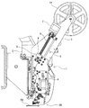
図2は1つのシークイン送り装置1の部分を拡大して示す右側面図、図3はその左側面図、図4はその正面図であってシークイン送り装置1のみを示したものである。シークイン送り装置1をミシンヘッドHに取り付けるためのベース部材として、針棒ケース2の左側面に固定されたベース3と、該固定ベース3に昇降可能に配置された取付ベース4とが設けられている。ベース3には2本の案内ロッド5が固定してあるとともに、ねじ軸6が軸支してある(図3において、もう1本の案内ロッド5はねじ軸6の裏側に位置している)。ねじ軸6はベース3に固定されたモータ7のモータ軸に連結してある。取付ベース4には、2本の案内ロッド5にスライド可能に嵌合された移動体8が固定してある。移動体8にはねじ軸6に螺合したナット部材9が固定してある。これにより、モータ7の駆動によってねじ軸6が回転すると、取付ベース4が案内ロッド5に沿って、シークイン送り装置1がシークインの縫い付けを行う下降位置と、シークイン送り装置1がシークインの縫い付けを行わない退避位置との間で昇降されることとなる。なお、図2及び図3は、シークイン送り装置1が上記下降位置に位置している状態を示しており、図5及び図6は、シークイン送り装置1が上記退避位置に位置している状態を示している。更に、取付ベース4には、該取付ベース4が下降位置にあるときにベース3の左右両面にその先端を突出して固定した両位置決め板11の間に嵌合する位置決めブロック12が固定してある。この位置決めブロック12が両位置決め板11の間に嵌合することにより、下降位置にある取付ベース4の左右(横方向)の位置決めがされる。
[First Example]
First, the sequin feeder 1 according to the first embodiment will be described.
FIG. 2 is an enlarged right side view showing a part of one sequin feed device 1, FIG. 3 is a left side view thereof, and FIG. 4 is a front view thereof showing only the sequin feed device 1. FIG. As a base member for attaching the sequin feeder 1 to the sewing machine head H, a base 3 fixed to the left side surface of the needle bar case 2 and an attachment base 4 arranged to be movable up and down on the fixed base 3 are provided. Yes. Two guide rods 5 are fixed to the base 3 and a screw shaft 6 is pivotally supported (in FIG. 3, the other guide rod 5 is located on the back side of the screw shaft 6). . The screw shaft 6 is connected to a motor shaft of a motor 7 fixed to the base 3. A moving body 8 slidably fitted to two guide rods 5 is fixed to the mounting base 4. A nut member 9 screwed onto the screw shaft 6 is fixed to the moving body 8. As a result, when the screw shaft 6 is rotated by driving the motor 7, the mounting base 4 is moved along the guide rod 5 and the sequin feed device 1 is sewn in a sewn position, and the sequin feed device 1 is sewn in the sequin. It will be moved up and down between the retreat positions where no operation is performed. 2 and 3 show a state where the sequin feed device 1 is located at the lowered position, and FIGS. 5 and 6 show a state where the sequin feed device 1 is located at the retracted position. Show. Furthermore, the mounting base 4 is fixed with a positioning block 12 that fits between both positioning plates 11 whose front ends protrude and are fixed to the left and right sides of the base 3 when the mounting base 4 is in the lowered position. . When the positioning block 12 is fitted between the positioning plates 11, the mounting base 4 at the lowered position is positioned left and right (lateral direction).

1つのシークイン送り装置1は、大別して、2つのシークイン送りユニット20,21と、該2つのシークイン送りユニット20,21のうち1つのユニットを選択して所定の縫い動作位置に位置決めするシークイン選択機構(図7等を参照して後述する符号44〜50,60〜67等の部分)と、所定の縫い動作位置に位置決めされた1つのシークイン送りユニットのシークイン送り機構19に係合して、縫い動作に応じて該係合したシークイン送り機構19を駆動し、シークイン連結体13を所定の切断位置に向けて送り出す送り駆動機構(図7等を参照して後述する符号51〜59等の部分)とを備えている。これらのシークイン送りユニット20,21、シークイン選択機構(44〜50,60〜67等)、送り駆動機構(51〜59等)は、前記取付ベース4に搭載されており、前記固定ベース3に対する該取付ベース4の上記昇降に伴い、シークインの縫い付けを行わない退避位置と、シークインの縫い付けを行う下降位置との間で、これらが昇降される。   One sequin feed device 1 is roughly divided into two sequin feed units 20, 21 and a sequin selection mechanism for selecting one of the two sequin feed units 20, 21 and positioning it at a predetermined sewing operation position. (Parts indicated by reference numerals 44 to 50, 60 to 67 and the like which will be described later with reference to FIG. 7 and the like) and the sequin feed mechanism 19 of one sequin feed unit positioned at a predetermined sewing operation position, According to the operation, the engaged sequin feed mechanism 19 is driven to feed the sequin coupling body 13 toward a predetermined cutting position (parts 51-59 and the like which will be described later with reference to FIG. 7). And. These sequin feed units 20 and 21, a sequin selection mechanism (44 to 50, 60 to 67, etc.), and a feed drive mechanism (51 to 59, etc.) are mounted on the mounting base 4, and are connected to the fixed base 3. As the mounting base 4 is raised and lowered, these are raised and lowered between a retracted position where the sequin is not sewn and a lowered position where the sequin is sewn.

また、各シークイン送りユニット20,21は、シークイン連結体13を所定の切断位置に向けて送り出すためのシークイン送り機構19と、該所定の切断位置に配置されたシークイン切断用のカッター部(図7等を参照して後述する符号36,23bの部分)とをそれぞれ含む。ここで、各シークイン送りユニット20,21に対応してシークイン連結体13を供給するために、所望のシークイン連結体13を巻回したリール(シークイン収納部)14が、図4に示すように2系列で設けられている。各シークイン送りユニット20,21に対応するリール14には、それぞれ任意の形状、色、サイズ(針通し孔から外縁までの寸法に応じた送りサイズ)のシークインを連結してなるシークイン連結体13を巻回して収納している。すなわち、1つのシークイン送り装置1を使用して、1つの刺繍柄において縫い付けされるべきシークインとして2種類の異なるシークインを適宜組み合わせて、シークイン縫いを行うことができるようになっており、そのような組み合わせシークイン縫いデザインの目的にあった2種類の異なるシークインのシークイン連結体13をそれぞれ収納した2つのリール14(供給源)が、図4に示すように、セットされる。例えば、図4で、左側のリール14が左側のシークイン送りユニット20に対応し、右側のリール14が右側のシークイン送りユニット21に対応している。   Each sequin feed unit 20, 21 includes a sequin feed mechanism 19 for feeding the sequin coupling body 13 toward a predetermined cutting position, and a sequin cutting cutter section (FIG. 7) arranged at the predetermined cutting position. , And the like, which will be described later with reference to FIG. Here, in order to supply the sequin coupling body 13 corresponding to each sequin feeding unit 20, 21, the reel (sequin storage part) 14 around which the desired sequin coupling body 13 is wound is provided as shown in FIG. It is provided in series. The reel 14 corresponding to each sequin feed unit 20, 21 has a sequin coupling body 13 formed by connecting sequins of any shape, color, and size (feed size according to the dimension from the needle through hole to the outer edge). It is wound and stored. That is, by using one sequin feeding device 1, sequins can be sewn by appropriately combining two different sequins as sequins to be sewn in one embroidery pattern. As shown in FIG. 4, two reels 14 (supply sources) each storing sequin coupling bodies 13 of two different kinds of sequins that are suitable for the purpose of the combination sequin design are set. For example, in FIG. 4, the left reel 14 corresponds to the left sequin feed unit 20, and the right reel 14 corresponds to the right sequin feed unit 21.

これらの2個のリール14は、図4に示すように、固定ベース3に設けられたリール取付軸に対して同軸で並列に取り付けられる。更に、固定ベース3には、各リール14から繰り出されたシークイン連結体13を案内する第1ローラ15、第2ローラ16、第3ローラ17が支持してあり、また、取付ベース4には第4ローラ18が支持してある。これらの各ローラもそれぞれ2個並列に設けてある。また、第1ローラ15、第2ローラ16の間には2つのテンションローラ10が設けてある。テンションローラ10はそれぞれ第1ローラ15、第2ローラ16の軸上に回動可能に設けられたテンションベース72、73に支持してある。第1ローラ15、第2ローラ16の軸上にはトーションバネ(図示省略)が設けてあり、図2においてテンションベース72は時計方向に、テンションベース73は半時計方向に付勢され、常にはベース3に固定したストッパ74にそれぞれ当接している。   As shown in FIG. 4, these two reels 14 are coaxially mounted in parallel with the reel mounting shaft provided on the fixed base 3. Further, the fixed base 3 supports a first roller 15, a second roller 16, and a third roller 17 that guide the sequin coupling body 13 fed out from each reel 14, and the mounting base 4 has a first roller 15. Four rollers 18 are supported. Two of each of these rollers are also provided in parallel. Two tension rollers 10 are provided between the first roller 15 and the second roller 16. The tension roller 10 is supported by tension bases 72 and 73 which are rotatably provided on the shafts of the first roller 15 and the second roller 16, respectively. Torsion springs (not shown) are provided on the shafts of the first roller 15 and the second roller 16, and in FIG. 2, the tension base 72 is urged clockwise and the tension base 73 is urged counterclockwise. The stopper 74 fixed to the base 3 is in contact with each other.

リール14から繰り出したシークイン連結体13は、第1ローラ15、テンションローラ10、第2ローラ16、第3ローラ17、第4ローラ18の順に図2に示すよう掛け渡され、取付ベース4に設けたシークイン送り機構19へと案内される。これにより、取付ベース4が退避位置に退避するときには、第4ローラ18によってシークイン連結体13が適切に手繰り上げられることになり、退避位置へ移動する時に、シークイン連結体13が余って大きく弛むことが起こらない。   The sequin coupling body 13 fed out from the reel 14 is passed over the first roller 15, the tension roller 10, the second roller 16, the third roller 17, and the fourth roller 18 in this order as shown in FIG. The sequin feed mechanism 19 is guided. As a result, when the mounting base 4 is retracted to the retracted position, the sequin coupled body 13 is appropriately lifted by the fourth roller 18, and the sequin coupled body 13 is excessively loosened when moving to the retracted position. Does not happen.

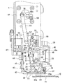
図7はシークイン送り装置1におけるシークイン送りユニット20,21、シークイン選択機構(44〜50,60〜67等)、送り駆動機構(51〜59等)の部分を更に拡大して背面側から見た斜視図、図8はその背面図、図9は図8のI−I線断面図である。これらの図より明らかなように、取付ベース4において2つのシークイン送りユニット20,21が対向して設けられており、これらのユニット20,21は、取付ベース4に設けられたスライド用のロッド47,48に沿って該取付ベース4に対して横スライド可能となっている。このスライド動作は、シークイン選択機構(44〜50,60〜67等)によって行われ、シークイン送りユニット20,21のどちらか一方を選択して送り駆動機構(51〜59等)に連結させ、該送り駆動機構(51〜59等)の駆動力を該連結された一方のシークイン送りユニット20,21に伝達することで、該選択された1つのシークイン送りユニット20,21からシークインを送り出すようにしている。   FIG. 7 is a further enlarged view of sequin feed units 20 and 21, sequin selection mechanisms (44 to 50, 60 to 67, etc.) and feed drive mechanisms (51 to 59, etc.) in the sequin feeder 1 as seen from the back side. FIG. 8 is a rear view thereof, and FIG. 9 is a cross-sectional view taken along the line II of FIG. As is apparent from these drawings, two sequin feed units 20 and 21 are provided facing each other in the mounting base 4, and these units 20 and 21 are provided with a sliding rod 47 provided on the mounting base 4. , 48 can be slid horizontally with respect to the mounting base 4. This sliding operation is performed by a sequin selection mechanism (44-50, 60-67, etc.), and either one of the sequin feed units 20, 21 is selected and connected to a feed drive mechanism (51-59, etc.) By transmitting the driving force of the feed drive mechanism (51-59, etc.) to the one connected sequin feed unit 20, 21, the sequin is sent out from the selected one sequin feed unit 20, 21. Yes.

対向して設けられた2つのシークイン送りユニット20,21は同一の機械的要素で構成されているものであるが、両者間ではその機械的配置及び形状が対称性をなしている。そこで、図9を参照して、一方のシークイン送りユニット20についてのみ、その各構成要素の詳細を説明する。1つのシークイン送りユニット20は、大別して、支持プレート22と、該支持プレート22の下端にて水平に設けられた支承板23と、該支持プレート22に搭載された各種要素(符号24〜35等)で構成されるシークイン送り機構19と、支承板23の先端の切断位置に配置されたカッター部(固定刃23bと可動刃36)とで構成される。対応するリール14から繰り出されたシークイン連結体13が支承板23上に導かれ、シークイン送り機構19によって切断位置つまりカッター部の方に送られるようになっている。支承板23には前後方向(Y方向)に適宜の幅のスリット23aが設けてある(図10参照)。このスリット23aには、後述するように、シークイン送り機構19におけるロックレバー33の係合爪33aが侵入しうるようになっている。   The two sequin feed units 20 and 21 provided opposite to each other are composed of the same mechanical elements, but the mechanical arrangement and shape are symmetrical between the two. Therefore, with reference to FIG. 9, only the one sequin feed unit 20 will be described in detail. One sequin feed unit 20 is roughly divided into a support plate 22, a support plate 23 provided horizontally at the lower end of the support plate 22, and various elements (reference numerals 24-35, etc.) mounted on the support plate 22. ) And a cutter part (fixed blade 23b and movable blade 36) disposed at the cutting position of the tip of the support plate 23. The sequin coupling body 13 fed out from the corresponding reel 14 is guided onto the support plate 23 and is fed by the sequin feeding mechanism 19 toward the cutting position, that is, toward the cutter portion. The support plate 23 is provided with a slit 23a having an appropriate width in the front-rear direction (Y direction) (see FIG. 10). As will be described later, the engaging claw 33a of the lock lever 33 in the sequin feed mechanism 19 can enter the slit 23a.

まず、シークイン送り機構19について詳細を説明する。支持プレート22に支持された軸24には連係アーム25が固定してあり、連係アーム25の自由端には先端に傾斜面が形成された連係ピン26が固定してある。軸24には揺動アーム27がネジ28により固定してあり、揺動アーム27の自由端には、先端に引掛け部29aの形成された送りレバー29が軸30により回動自由に支持されている。軸30には送りレバー29を時計方向に付勢するトーションバネ(図示省略)が設けてあり、送りレバー29の先端側が常に支承板23に接近する方向に付勢される。また、この送りレバー29の時計方向への付勢によって、揺動アーム27がストッパ31と当接する方向へ付勢される。ストッパ31は、支持プレート22に固定したブラケット32に螺着されたネジ棒からなり、ナットの締め付けによりロックされるもので、その後端に揺動アーム27が当接する。送りレバー29の上方にはロックレバー33が設けてある。ロックレバー33は、一端側の先端に係合爪(係合突起)33aが、他端側にストッパ部33bが形成されており、その中間部が、支持プレート22に取付けられた支持ブロック34に対してピン35により回動自由に支持してある。ロックレバー33の係合爪33aは送りレバー29に形成された透孔29bを貫通している。支持ブロック34に設けられたピン35にはトーションバネ(図示省略)が設けられており、該トーションバネによりロックレバー33は反時計方向に回動付勢されている。この回動付勢により、ロックレバー33は自由状態においてはストッパ部33bが支持ブロック34の受止め部34aに当接し、係合爪33aの端部が支承板23のスリット23a内に臨む姿勢に保持されるようになっている。この姿勢に保持されたロックレバー33の係合爪33aは、支承板23上に導かれたシークイン連結体13のうちの1つのシークインSの縫止孔Saに係合し、縫い付け時(切断時)にシークイン連結体13を移動不能にロックする。   First, details of the sequin feed mechanism 19 will be described. A linkage arm 25 is fixed to the shaft 24 supported by the support plate 22, and a linkage pin 26 having an inclined surface formed at the tip is fixed to the free end of the linkage arm 25. A swing arm 27 is fixed to the shaft 24 with a screw 28, and a feed lever 29 having a hook portion 29 a formed at the tip of the swing arm 27 is rotatably supported by a shaft 30 at the free end of the swing arm 27. ing. The shaft 30 is provided with a torsion spring (not shown) that urges the feed lever 29 in the clockwise direction, and the tip end side of the feed lever 29 is always urged in a direction approaching the support plate 23. Further, the oscillating arm 27 is urged in the direction in which it abuts against the stopper 31 by the urging of the feed lever 29 in the clockwise direction. The stopper 31 is a screw rod screwed to a bracket 32 fixed to the support plate 22 and is locked by tightening a nut. The swing arm 27 abuts on the rear end thereof. A lock lever 33 is provided above the feed lever 29. The lock lever 33 has an engagement claw (engagement protrusion) 33 a at the tip on one end side and a stopper portion 33 b on the other end side, and an intermediate portion of the lock lever 33 on the support block 34 attached to the support plate 22. On the other hand, it is supported by a pin 35 so as to freely rotate. The engaging claw 33 a of the lock lever 33 passes through a through hole 29 b formed in the feed lever 29. A pin 35 provided on the support block 34 is provided with a torsion spring (not shown), and the lock lever 33 is urged to rotate counterclockwise by the torsion spring. By this urging force, the lock lever 33 is in a posture in which the stopper portion 33b contacts the receiving portion 34a of the support block 34 in the free state, and the end portion of the engaging claw 33a faces the slit 23a of the support plate 23. It is supposed to be retained. The engaging claw 33a of the lock lever 33 held in this posture engages with the sewing hole Sa of one sequin S of the sequin coupling body 13 guided on the support plate 23, and is sewn (disconnected). The sequin coupling 13 is locked so as not to move.

次に、固定刃23bと可動刃36とで構成されるカッター部について詳細を説明する。支承板23の先端には可動刃36がピン37により回動自由に支持してあり、トーションバネ38によって常には支承板23の端縁に形成された固定刃23bから上方に離間した退避姿勢に保持されている。可動刃36は針棒39が下降したときその下端の針抱き40により押されるようになっており、針抱き40により押されると、トーションバネ38の弾力に抗して揺動し、固定刃23bと協働して先端のシークインSの接合部Sb(図10参照)を切断する。針棒39とともに針抱き40が上昇すると、可動刃36はトーションバネ38の復元力により退避姿勢に戻る。   Next, the details of the cutter unit composed of the fixed blade 23b and the movable blade 36 will be described. A movable blade 36 is rotatably supported by a pin 37 at the tip of the support plate 23, and is always in a retracted position spaced upward from a fixed blade 23b formed on the end edge of the support plate 23 by a torsion spring 38. Is retained. The movable blade 36 is pushed by a needle clamp 40 at the lower end of the needle bar 39, and when it is pressed by the needle clamp 40, it swings against the elasticity of the torsion spring 38, and the fixed blade 23b. The joint Sb (see FIG. 10) of the sequin S at the tip is cut in cooperation with the above. When the needle holder 40 rises together with the needle bar 39, the movable blade 36 returns to the retracted posture by the restoring force of the torsion spring 38.

次に、リール14から繰り出されたシークイン連結体13を各シークイン送りユニット20又は21にガイドするためのガイド機構について、図9を参照して説明する。支持プレート22にはブラケット41が固定してあり、ブラケット41にはシークイン連結体13を支承板23上に導くガイド部42が設けてある。ガイド部42はシークイン連結体13の幅に応じて交換可能となっている。ブラケット41には、バネ鋼鈑のような弾力を有する板材で形成した押え部材43が固定してある。押え部材43は、その自由端が支承板23の上面に弾接しており、ガイド部42から導いたシークイン連結体13をその間に挿通させるようになっている。   Next, a guide mechanism for guiding the sequin coupling body 13 fed out from the reel 14 to each sequin feed unit 20 or 21 will be described with reference to FIG. A bracket 41 is fixed to the support plate 22, and a guide portion 42 that guides the sequin coupling body 13 onto the support plate 23 is provided on the bracket 41. The guide part 42 can be exchanged according to the width of the sequin coupling body 13. A pressing member 43 formed of a plate material having elasticity such as a spring steel plate is fixed to the bracket 41. The free end of the pressing member 43 is in elastic contact with the upper surface of the support plate 23, and the sequin coupling body 13 guided from the guide portion 42 is inserted therebetween.

次に、シークイン選択機構(44〜50,60〜67等)について説明する。上記構成からなるシークイン送りユニット20、21は、図7に示すように、それぞれ固定ブラケット44を介して、スライドプレート45に固定してある。スライドプレート45の左右端部にはスライド体46が固定してある。両スライド体46は取付ベース4に固定された第1ロッド47に摺動自在に支持してある。両固定ブラケット44には第2ロッド48が掛け渡して設けてある。第2ロッド48は支持部材49の2つの支持部49aに摺動自在に支持してある。支持部材49はブラケット50に固定してあり、ブラケット50は取付ベース4に固定されている(詳しくは軸受体51を介して取付ベース4に固定してある)。   Next, the sequin selection mechanism (44-50, 60-67, etc.) will be described. The sequin feed units 20 and 21 having the above-described configuration are fixed to the slide plate 45 via fixing brackets 44 as shown in FIG. A slide body 46 is fixed to the left and right ends of the slide plate 45. Both slide bodies 46 are slidably supported by a first rod 47 fixed to the mounting base 4. A second rod 48 is provided over both fixed brackets 44. The second rod 48 is slidably supported on the two support portions 49 a of the support member 49. The support member 49 is fixed to the bracket 50, and the bracket 50 is fixed to the mounting base 4 (specifically, the bracket 50 is fixed to the mounting base 4 via the bearing body 51).

なお、図7は、一方の(以下、「第1の」という)シークイン送りユニット20が選択されている状態を示している。図11は、図7の状態におけるシークイン送りユニット20,21とシークイン選択機構の部分を更に拡大して示す正面図である。図12は、図11と同様の正面図であるが、他方の(以下、「第2の」という)シークイン送りユニット21が選択されている状態を示している。また、図13は、図7と同様の斜視図であるが、図12のように他方のシークイン送りユニット21が選択されている状態を示している。   FIG. 7 shows a state in which one (hereinafter referred to as “first”) sequin feed unit 20 is selected. FIG. 11 is an enlarged front view of the sequin feed units 20 and 21 and the sequin selection mechanism in the state of FIG. FIG. 12 is a front view similar to FIG. 11, but shows a state where the other (hereinafter referred to as “second”) sequin feed unit 21 is selected. 13 is a perspective view similar to FIG. 7, but shows a state where the other sequin feed unit 21 is selected as shown in FIG.

図11より明らかなように、スライドプレート45には連結アーム60の一端が枢支してある。連結アーム60の他端は、取付ベース4に固定されたモータベース61に回動可能に支持された回動アーム62の一端と連結してある。モータベース61に固定されたモータ63のモータ軸には駆動アーム64が固定してあり、駆動アーム64の自由端は回動アーム62の他端に連結目金65を介して連結してある。これにより、モータ63を往復駆動すると、2つのシークイン送りユニット20,21が一体的に左右に(横方向つまりX方向に)スライドすることとなる。第1ロッド47にはシークイン送りユニット20,21のスライド位置の限界を規定する規制部材66が、左側のスライド体46の左右両側にそれぞれ設けてある。図11に示すように、左側のスライド体46が右側の規制部材66に緩衝体67を介して当接したスライド位置のときは、第1のシークイン送りユニット20を選択してこれを所定の縫い動作位置に位置決めした状態である。なお、図8は、同様に第1のシークイン送りユニット20が選択された状態を示している。このように第1のシークイン送りユニット20を選択して所定の縫い動作位置に位置決めした状態においては、図8に示すように、該第1のシークイン送りユニット20の連係アーム25の連係ピン26が、送り駆動機構(51〜59等)における伝達レバー54の係合部54aと係合するとともに、該第1のシークイン送りユニット20によって送り出すシークインSの縫止孔Saが針落ち位置(針板70の針通し孔71の位置)と合致する。   As apparent from FIG. 11, one end of the connecting arm 60 is pivotally supported on the slide plate 45. The other end of the connecting arm 60 is connected to one end of a rotating arm 62 that is rotatably supported by a motor base 61 fixed to the mounting base 4. A drive arm 64 is fixed to the motor shaft of the motor 63 fixed to the motor base 61, and the free end of the drive arm 64 is connected to the other end of the rotating arm 62 via a connecting metal 65. Accordingly, when the motor 63 is driven to reciprocate, the two sequin feed units 20 and 21 are integrally slid left and right (laterally, that is, in the X direction). The first rod 47 is provided with restricting members 66 for defining the limit of the slide position of the sequin feed units 20 and 21 on the left and right sides of the left slide body 46, respectively. As shown in FIG. 11, when the left slide body 46 is in the slide position where it abuts against the right regulating member 66 via the buffer body 67, the first sequin feed unit 20 is selected and this is sewn to a predetermined stitch. It is in a state where it is positioned at the operating position. FIG. 8 similarly shows a state where the first sequin feed unit 20 is selected. In this state where the first sequin feed unit 20 is selected and positioned at a predetermined sewing operation position, as shown in FIG. 8, the link pin 26 of the link arm 25 of the first sequin feed unit 20 is In addition, the sewing hole Sa of the sequin S that is engaged with the engaging portion 54a of the transmission lever 54 in the feed drive mechanism (51 to 59, etc.) and fed by the first sequin feed unit 20 is in the needle drop position (the needle plate 70). And the position of the needle-passing hole 71).

一方、図12に示すように、左側のスライド体46が左側の規制部材66に緩衝体67を介して当接したスライド位置のときは、第2のシークイン送りユニット21を選択してこれを所定の縫い動作位置に位置決めした状態である。この状態では、第2のシークイン送りユニット21の連係ピン26が送り駆動機構(51〜59等)における伝達レバー54の係合部54aと係合する(図13参照)とともに、送りユニット21にて送り出すシークインSの縫止孔Saが針落ち位置(針板70の針通し孔71の位置)と合致する。このように、2つのシークイン送りユニット20,21を一体的にスライドさせることでいずれかのユニット20、21が選択的に所定の縫い動作位置に位置決めされる。そして、後述するように、選択した送りユニットを使用してシークインの縫い付けが行われるようになる。なお、変形例として、2つのシークイン送りユニット20,21を一体的にスライドさせることなく、どちらか一方を選択的に動かすことで、一方のシークイン送りユニットを選択的に所定の縫い動作位置に位置決めするように設計変更することも可能である。   On the other hand, as shown in FIG. 12, when the left slide body 46 is in the slide position where it abuts the left regulating member 66 via the buffer body 67, the second sequin feed unit 21 is selected and set to a predetermined position. The sewing machine is positioned at the sewing operation position. In this state, the linkage pin 26 of the second sequin feed unit 21 is engaged with the engaging portion 54a of the transmission lever 54 in the feed drive mechanism (51 to 59, etc.) (see FIG. 13), and at the feed unit 21 The sewing hole Sa of the sequin S to be fed coincides with the needle drop position (the position of the needle passage hole 71 of the needle plate 70). In this way, by sliding the two sequin feed units 20 and 21 together, one of the units 20 and 21 is selectively positioned at a predetermined sewing operation position. As will be described later, sequins are sewn using the selected feed unit. As a modification, one sequin feed unit is selectively positioned at a predetermined sewing operation position by selectively moving one of the two sequin feed units 20 and 21 without sliding them integrally. It is also possible to change the design.

なお、一連のシークイン模様縫いを行っている途中で縫い付けるべきシークインを切り替えるために、シークイン送りユニット20又は21を選択するために行うシークイン選択機構(44〜50,60〜67等)によるスライド動作は、針棒39が上方にある間に行うようにする。そうすれば、シークインを切り替えるために針棒39の上下動を休止(所謂ジャンプ)しなくともよいことになり、縫い作業の効率が向上する。   In addition, a sliding operation by a sequin selection mechanism (44 to 50, 60 to 67, etc.) performed to select the sequin feed unit 20 or 21 in order to switch the sequin to be sewn while performing a series of sequin pattern sewing. Is performed while the needle bar 39 is in the upper position. Then, it is not necessary to pause (so-called jump) the vertical movement of the needle bar 39 in order to switch sequins, and the efficiency of the sewing work is improved.

次に、送り駆動機構(51〜59等)について説明する。図7あるいは図9を参照すると、取付ベース4に取り付けられた前記軸受体51には回動軸52が回動自在に支持してあり、回動軸52には従動レバー53及び伝達レバー54が固定してある。伝達レバー54の自由端には、各シークイン送りユニット20,21の前記連係アーム25の前記連係ピン26と係合するU字状の凹部からなる係合部54aが形成してある。このU字状の凹部からなる係合部54aは、上述のようにシークイン送りユニット20,21が横方向にスライドされるとき、各ユニット20,21の連係ピン26が該係合部54aに対して相対的に横方向に動くことを許し、これによって、選択された1つのシークイン送りユニット20,21の連係ピン26のみが係合部54aに係合することとなる。なお、各連係ピン26の先端には傾斜面を形成しておき、その係合がスムーズに行われるようにするとよい。なお、このような傾斜面は伝達レバー54の係合部54aの側に形成してもよいし、あるいは、連係ピン26と係合部54aの双方に形成してもよい。   Next, the feed drive mechanism (51 to 59, etc.) will be described. Referring to FIG. 7 or FIG. 9, a rotating shaft 52 is rotatably supported on the bearing body 51 attached to the attachment base 4, and a driven lever 53 and a transmission lever 54 are supported on the rotating shaft 52. It is fixed. At the free end of the transmission lever 54, an engaging portion 54a formed of a U-shaped recess that engages with the linkage pin 26 of the linkage arm 25 of each sequin feed unit 20, 21 is formed. When the sequin feed units 20 and 21 are slid in the horizontal direction as described above, the engaging pin 54 of the U-shaped recess is formed so that the linking pin 26 of each unit 20 and 21 is relative to the engaging portion 54a. Therefore, only the linkage pin 26 of one selected sequin feed unit 20, 21 is engaged with the engaging portion 54a. In addition, it is good to form the inclined surface in the front-end | tip of each linkage pin 26 so that the engagement may be performed smoothly. Such an inclined surface may be formed on the engaging portion 54a side of the transmission lever 54, or may be formed on both the linkage pin 26 and the engaging portion 54a.

従動レバー53の自由端は連結リンク55を介して駆動レバー56の自由端に連結してある。駆動レバー56は、取付ベース4の左側面に固定されたモータ57のモータ軸に固定してある。回動軸52にはトーションバネ58が設けてあり、従動レバー53及び伝達レバー54が図9において時計方向に揺動付勢され、常には駆動レバー56の当接片56aがストッパ59と当接することとなる。シークインを送り出す場合は、モータ57を図9において反時計方向に所定角度だけ回動し、その後、時計方向に所定角度だけ回動する(戻す)、という所定角度範囲の1往復ストローク駆動を行う。   The free end of the driven lever 53 is connected to the free end of the drive lever 56 via a connecting link 55. The drive lever 56 is fixed to the motor shaft of the motor 57 fixed to the left side surface of the mounting base 4. The rotation shaft 52 is provided with a torsion spring 58, and the driven lever 53 and the transmission lever 54 are oscillated and urged clockwise in FIG. 9, and the contact piece 56 a of the drive lever 56 is always in contact with the stopper 59. It will be. In order to send out sequins, the motor 57 is rotated by a predetermined angle in the counterclockwise direction in FIG. 9, and then rotated (returned) by a predetermined angle in the clockwise direction for one reciprocating stroke drive within a predetermined angle range.

次に、シークイン送り機構19によるシークイン送り動作について説明する。往動時における前記モータ57の反時計方向の回転駆動に応じて、駆動レバー56が反時計方向に所定角度だけ回動され、連結リンク55の下端と従動レバー53の自由端との連結点が下向きに反時計方向に所定角度だけ回動され、これに伴い、回動軸52が反時計方向に所定角度だけ回動され、伝達レバー54の下端の係合部54aが後方(図9で右方向つまり反時計方向)に駆動される。この係合部54aの後方駆動に応じて、該係合部54aに係合している1つの送りユニット(20又は21)のシークイン送り機構19の連係ピン26が一緒に後方に動く。該1つの送りユニット(20又は21)のシークイン送り機構19では、連係ピン26の動きに応じて、軸24を中心にして、連係アーム25及び揺動アーム27が図9で時計方向に動かされ、該揺動アーム27の自由端(下端)に支持されている送りレバー29が前方(図9で左方向)に動かされる。次に、復動時のモータ57の時計方向の回転駆動に応じて、各要素が、上述とは逆方向に動かされ、揺動アーム27の自由端(下端)に支持されている送りレバー29が後方(図9で右方向つまり所定の切断位置の方向)に動かされる。   Next, the sequin feed operation by the sequin feed mechanism 19 will be described. In accordance with the counterclockwise rotational drive of the motor 57 during the forward movement, the drive lever 56 is rotated counterclockwise by a predetermined angle, and the connection point between the lower end of the connection link 55 and the free end of the driven lever 53 is It is rotated downward by a predetermined angle in the counterclockwise direction, and accordingly, the rotation shaft 52 is rotated counterclockwise by a predetermined angle, and the engaging portion 54a at the lower end of the transmission lever 54 is moved backward (right in FIG. 9). Direction, ie counterclockwise). In response to the rear drive of the engaging portion 54a, the linkage pin 26 of the sequin feed mechanism 19 of one feed unit (20 or 21) engaged with the engaging portion 54a moves rearward together. In the sequin feed mechanism 19 of the one feed unit (20 or 21), the linkage arm 25 and the swing arm 27 are moved clockwise in FIG. 9 around the shaft 24 according to the movement of the linkage pin 26. The feed lever 29 supported by the free end (lower end) of the swing arm 27 is moved forward (leftward in FIG. 9). Next, each element is moved in the opposite direction to that described above in accordance with the clockwise rotation drive of the motor 57 during the backward movement, and the feed lever 29 supported by the free end (lower end) of the swing arm 27. Is moved backward (in the right direction in FIG. 9, that is, in the direction of a predetermined cutting position).

往動時又は復動時における該送りレバー29の1ストローク長が、シークイン連結体13の1ピッチ分の送り量にほぼ対応している。このシークイン送り動作は、前述の特許文献4(特開2004-167097号公報)に詳しく説明されているように、図10に示す先端のシークインSの縫い付け(及びそれに伴う接合部Sbでの切断)が終わった後に行われる。このとき、次のシークインS1の縫止孔に送りレバー29の先端の引掛け部29aが係合しており、かつ、前述のロックレバー33の係合爪33aが、そのいくつか(例えば2つ)後に続くシークインの縫止孔に係合している。   One stroke length of the feed lever 29 at the time of forward movement or backward movement substantially corresponds to the feed amount of one pitch of the sequin coupling body 13. As described in detail in the above-mentioned Patent Document 4 (Japanese Patent Laid-Open No. 2004-167097), the sequin feeding operation is performed by sewing the sequin S at the tip end shown in FIG. 10 (and cutting at the joint Sb associated therewith). ) Is done. At this time, the hook portion 29a at the tip of the feed lever 29 is engaged with the sewing hole of the next sequin S1, and the engaging claws 33a of the lock lever 33 are some of them (for example, two ) Engage with the sequin hole that follows.

このシークイン送り動作は、前述の特許文献4(特開2004-167097号公報)において詳しく説明されているものと同じであるが、以下、簡単に説明する。往動時に、前述のように送りレバー29が前方(図9,図10で左方向)に動かされると、まず、送りレバー29の引掛け部29aがシークインS1の縫止孔から抜け出すが、この抜け出し時にはまだロックレバー33の係合爪33aが後続のシークインの縫止孔に係合したままとなっているため、送りレバー29の引掛け部29aがシークインS1の縫止孔から抜け出る際の衝動でシークイン連結体13が移動してしまうのが確実に防止される。この状態から送りレバー29がさらに前方(図9,図10で左方向)に動くと、送りレバー29の透孔29bの口縁との係合によってロックレバー33が前記トーションバネの付勢力に抗して図9で時計方向に回動し、その係合爪33aがシークインから上方に離間し、該係合爪33aのシークインの縫止孔に対する係合が解かれる。そして、往動ストロークの終わりでは、送りレバー29の引掛け部29aがシークインS1の隣のシークインの縫止孔よりも少しだけ前方(図9,図10で左方向)に位置し(つまり縫止孔には入り込んでいない)、ロックレバー33も上方に位置したままになっている。なお、変形例として、往動ストロークの終わりでは、送りレバー29の引掛け部29aがシークインS1の隣のシークインの縫止孔に入り込むようにしてもよい。なお、往動ストローク時において、ロックレバー33の係合爪33aとの係合も解かれたシークイン連結体13は、押え部材43のバネ弾力によって押えられるので、送りレバー29の動きに伴って一緒に動くことはない。   This sequin feed operation is the same as that described in detail in the above-mentioned Patent Document 4 (Japanese Patent Laid-Open No. 2004-167097), but will be briefly described below. When the feed lever 29 is moved forward (leftward in FIGS. 9 and 10) as described above during the forward movement, first, the hooking portion 29a of the feed lever 29 comes out of the sewn hole of the sequin S1. At the time of withdrawal, the engaging claw 33a of the lock lever 33 is still engaged with the sewing hole of the subsequent sequin, so that the hooking portion 29a of the feed lever 29 is urged to come out of the sewing hole of the sequin S1. Therefore, it is possible to reliably prevent the sequin coupling body 13 from moving. When the feed lever 29 moves further forward (leftward in FIGS. 9 and 10) from this state, the lock lever 33 resists the urging force of the torsion spring by engagement with the lip of the through hole 29b of the feed lever 29. Then, it rotates clockwise in FIG. 9, and the engaging claw 33a is separated upward from the sequin, and the engagement of the engaging claw 33a with the sewn hole of the sequin is released. At the end of the forward stroke, the hooking portion 29a of the feed lever 29 is positioned slightly forward (leftward in FIGS. 9 and 10) slightly ahead of the sequin sewing hole adjacent to the sequin S1 (that is, the sewing stop). The lock lever 33 also remains in the upper position. As a modification, at the end of the forward stroke, the hooking portion 29a of the feed lever 29 may enter the sequin sewing hole adjacent to the sequin S1. During the forward stroke, the sequin coupling body 13 that has been disengaged from the engagement claw 33a of the lock lever 33 is pressed by the spring elasticity of the pressing member 43, so that it moves together with the movement of the feed lever 29. Never move.

次に、復動時に、前述のように送りレバー29が後方(図9,図10で右方向)に動かされると、送りレバー29の引掛け部29aがシークインS1の隣のシークインの縫止孔に係合し、その係合により、シークイン連結体13を所定の切断位置の方(図9,図10で右方向)に送り出す。その動きの過程で、送りレバー29の透孔29bの口縁がロックレバー33から離間すると、送りレバー29の透孔29bの口縁による係止が解かれて、ロックレバー33は、前記ピン35に設けられたトーションバネの弾力によって反時計方向に回動付勢される。これによって、該ロックレバー33の係合爪33aが、シークイン連結体13の上面に弾接し、シークインの上面を相対的に摺動する。復動ストロークの終わりでは、先端のシークインS1が図10に示す先端のシークインSと同様に、所定の切断位置(つまり縫い付け位置)に到達する。そして、上記したように、ロックレバー33の係合爪33aがシークイン連結体13の所定のシークインの縫止孔に係合する。   Next, when the feed lever 29 is moved rearward (rightward in FIGS. 9 and 10) as described above at the time of backward movement, the hooking portion 29a of the feed lever 29 is sewn in the sequin hole next to the sequin S1. The sequin coupling body 13 is sent out toward the predetermined cutting position (rightward in FIGS. 9 and 10). In the course of the movement, when the lip of the through hole 29b of the feed lever 29 is separated from the lock lever 33, the lock by the lip of the through hole 29b of the feed lever 29 is released, and the lock lever 33 is moved to the pin 35. It is urged to rotate counterclockwise by the elasticity of the torsion spring provided on. As a result, the engaging claw 33a of the lock lever 33 comes into elastic contact with the upper surface of the sequin coupling body 13 and slides relatively on the upper surface of the sequin. At the end of the backward movement stroke, the tip sequin S1 reaches a predetermined cutting position (that is, the sewing position) in the same manner as the tip sequin S shown in FIG. As described above, the engaging claw 33 a of the lock lever 33 engages with a predetermined sequin sewing hole of the sequin coupling body 13.

次に、各シークイン送りユニット20、21における切断位置(縫い針77に対する位置)の可変調整するための調整機構(68,69)につき説明する。図14は、一方のシークイン送りユニット21の支持プレート22をシークイン送り機構19が設けられた側とは反対側から見た側面図である。図14に示すように、支持プレート22はネジ68により固定ブラケット44に固定してある。固定ブラケット44のネジ68が貫通する孔44aは長孔に形成してある。固定ブラケット44には、その先端が支持プレート22に形成したネジ孔に螺合している調整ネジ(又はボルト)69が、回転自在であるがネジ軸方向には動かないように、設けてある。支持プレート22を固定しているネジ68を緩め、調整ネジ69を右回し又は左回しすることにより、支持プレート22が固定ブラケット44に対して前又は後に直線的に動かされて、その前後位置が調整される。所望の位置に調整したら、ネジ68を締めて支持プレート22を固定ブラケット44に固定する。
ところで、この支持プレート22の位置調整を行なうことによって、連係アーム25の連係ピン26の位置も前後動し、復帰位置にある伝達レバー54の係合部54aに対する位置関係が狂うことになるが、支持プレート22の位置調整を行う際には、連係アーム25を軸24に固定しているネジ81(図8参照)を予め緩めて連係アーム25をフリー状態にしておけば、支持プレート22を移動させたときに、復帰位置にある伝達レバー54が揺動することはなく、調整後にネジ81を締めて連係アーム25を軸24に固定すればよい。
Next, an adjustment mechanism (68, 69) for variably adjusting the cutting position (position with respect to the sewing needle 77) in each sequin feed unit 20, 21 will be described. FIG. 14 is a side view of the support plate 22 of one sequin feed unit 21 as viewed from the side opposite to the side where the sequin feed mechanism 19 is provided. As shown in FIG. 14, the support plate 22 is fixed to the fixing bracket 44 with screws 68. A hole 44a through which the screw 68 of the fixing bracket 44 passes is formed as a long hole. The fixing bracket 44 is provided with an adjustment screw (or bolt) 69 whose tip is screwed into a screw hole formed in the support plate 22 so that it can rotate but does not move in the screw shaft direction. . By loosening the screw 68 fixing the support plate 22 and turning the adjustment screw 69 clockwise or counterclockwise, the support plate 22 is linearly moved forward or backward with respect to the fixing bracket 44, and the front and rear positions thereof are changed. Adjusted. After the adjustment to the desired position, the screw 68 is tightened to fix the support plate 22 to the fixing bracket 44.
By the way, by adjusting the position of the support plate 22, the position of the linkage pin 26 of the linkage arm 25 also moves back and forth, and the positional relationship of the transmission lever 54 at the return position with respect to the engaging portion 54 a becomes out of order. When adjusting the position of the support plate 22, the screw 81 (see FIG. 8) that fixes the linkage arm 25 to the shaft 24 is loosened in advance so that the linkage arm 25 is in a free state. When this is done, the transmission lever 54 at the return position does not swing, and after adjustment, the screw 81 may be tightened to fix the linkage arm 25 to the shaft 24.

この支持プレート22の位置調整によって、当該シークイン送りユニット21の前後位置が調整されることになる。ミシンヘッドの針棒39に取り付けられた縫い針77の位置(水平方向位置)は相対的に固定されているので、このような当該シークイン送りユニット21の前後位置の調整によって、該縫い針77に対するカッター部(36,23b)の位置つまり切断位置(縫い針77の上下動軸線と固定刃23bとの間の水平方向の距離)が調整される。この切断位置は、当該シークイン送りユニット21にセットするシークイン連結体13のシークインのサイズ(図10に示す縫止孔Saから接合部Sbまでの距離)に応じて調整する。従って、当該送りユニット21に対応して取り付けられるリール(シークイン収納部)14を、それまでとは異なるサイズ(送りサイズ)のシークイン連結体13を収納したリール(シークイン収納部)14と交換するとき、この切断位置調整を行う。具体的には、例えば、シークイン連結体13を収納したリール14を新たに装着したとき、そこからシークイン連結体13を繰り出して支承板23の上に置き、その先端のシークインSを図10に示すように固定刃23bよりも先に出して接合部Sbが固定刃23bの位置に合致するようにした上で、該先端のシークインSの縫止孔Saの中心が縫い針77の中心に合致するように、調整ネジ69を右回し又は左回しして送りユニット21の前後位置を調整する。   By adjusting the position of the support plate 22, the front / rear position of the sequin feed unit 21 is adjusted. Since the position (horizontal direction position) of the sewing needle 77 attached to the needle bar 39 of the sewing machine head is relatively fixed, the adjustment of the front / rear position of the sequin feed unit 21 with respect to the sewing needle 77 is performed. The position of the cutter part (36, 23b), that is, the cutting position (the horizontal distance between the vertical movement axis of the sewing needle 77 and the fixed blade 23b) is adjusted. This cutting position is adjusted according to the sequin size of the sequin coupling body 13 set in the sequin feed unit 21 (distance from the sewing hole Sa to the joint Sb shown in FIG. 10). Therefore, when the reel (sequin storage portion) 14 attached corresponding to the feed unit 21 is replaced with the reel (sequin storage portion) 14 storing the sequin coupling body 13 of a different size (feed size) than before. Then, the cutting position is adjusted. Specifically, for example, when a reel 14 containing a sequin coupling body 13 is newly mounted, the sequin coupling body 13 is drawn out therefrom and placed on the support plate 23, and the sequin S at the tip thereof is shown in FIG. In this way, the joint Sb comes out before the fixed blade 23b so as to match the position of the fixed blade 23b, and the center of the sewing hole Sa of the sequin S at the tip matches the center of the sewing needle 77. As described above, the front and rear positions of the feed unit 21 are adjusted by turning the adjustment screw 69 clockwise or counterclockwise.

なお、このような倣い調整に限らず、装着したリール14に収納されたシークインの縫止孔Saから接合部Sbまでの距離のデータに基づき、縫い針77の中心から固定刃23bまでの距離を測定しながら、この測定距離が、該データによって示される距離に等しくなるように調整してもよい。また、データに基づく調整と倣い調整を組み合わせてもよい。更に、調整ネジ69に関連して適宜の目盛りを設けておき、調整ネジ69の現在設定状態と切断位置(縫い針77の中心から固定刃23bまでの距離)との対応が把握できるようにしてもよい。調整機構としては、調整ネジ69を用いたものに限らず、その他の直線変位機構を用いたものであってもよい。あるいは、調整ネジ69を設けることなく、支持プレート22を固定しているネジ68を緩めた状態で、手で支持プレート22を掴んで動かすことでその前後位置を調整するようにしてもよい。逆にリニアモータのような駆動手段を用いて対応するシークイン送りユニット20または21を自動的に直線変位させることでそれぞれの切断位置を可変調整するようにしてもよい。   The distance from the center of the sewing needle 77 to the fixed blade 23b is determined based on the distance data from the sewing hole Sa of the sequin stored in the mounted reel 14 to the joining portion Sb. While measuring, this measured distance may be adjusted to be equal to the distance indicated by the data. Further, adjustment based on data and copying adjustment may be combined. Further, an appropriate scale is provided in relation to the adjustment screw 69 so that the correspondence between the current setting state of the adjustment screw 69 and the cutting position (the distance from the center of the sewing needle 77 to the fixed blade 23b) can be grasped. Also good. The adjusting mechanism is not limited to the one using the adjusting screw 69 but may be one using another linear displacement mechanism. Alternatively, the front and rear positions of the support plate 22 may be adjusted by grasping and moving the support plate 22 by hand in a state where the screw 68 fixing the support plate 22 is loosened without providing the adjustment screw 69. Conversely, the cutting position may be variably adjusted by automatically linearly displacing the corresponding sequin feed unit 20 or 21 using a driving means such as a linear motor.

もう一方のシークイン送りユニット20の切断位置を調整する機構も上記と同様に構成されている。ただし、各シークイン送りユニット20,21は、それぞれ独立にその切断位置つまり縫い針77に対するカッター部(36,23b)の位置つまり切断位置が調整可能である。すなわち、各シークイン送りユニット20,21は、前述のスライドプレート45の動きに応じて固定ブラケット44と共に横方向には一体的にスライド可能であるが、前後方向に関してはそれぞれ固定ブラケット44に対して独立に位置調整可能であるから、それぞれ独立にその切断位置を調整することができる。こうして、各シークイン送りユニット20、21にセットされたシークイン連結体13のシークインのサイズ(シークインの縫止孔Saから接合部Sbまでの距離)に合わせて、それぞれの切断位置を調整すると、そのサイズが異なる場合には、図15に示すように、各送りユニット20、21の両支承板23の前後の配置位置つまりカッター部(36,23b)の位置が適宜異なることとなる。   The mechanism for adjusting the cutting position of the other sequin feed unit 20 is also configured in the same manner as described above. However, each sequin feed unit 20, 21 can independently adjust its cutting position, that is, the position of the cutter portion (36, 23b) with respect to the sewing needle 77, that is, the cutting position. That is, each sequin feed unit 20, 21 can be slid integrally with the fixed bracket 44 in the lateral direction according to the movement of the slide plate 45, but is independent of the fixed bracket 44 in the front-rear direction. Therefore, the cutting position can be adjusted independently. Thus, when the respective cut positions are adjusted in accordance with the sequin size (distance from the sequin sewn hole Sa to the joint Sb) of the sequin coupling body 13 set in each sequin feed unit 20, 21, If they are different, as shown in FIG. 15, the arrangement positions of the front and rear of the support plates 23 of the feeding units 20 and 21, that is, the positions of the cutter portions (36, 23b) are appropriately different.

次に、各シークイン送りユニット20、21におけるシークイン送り機構19のシークイン送り量(送りピッチ)の可変設定につき説明する。いずれかのシークイン送りユニット20、21において、送りピッチを調整すべきシークイン連結体13を収納したリール14を新たに装着したとき、該ユニット20又は21のシークイン送り機構19のシークイン送り量(送りピッチ)の調整を行う。まず、揺動レバー27を固定しているネジ28(図9参照)を緩め、回動軸24に対して揺動レバー27を手で容易に回せるようにする。また、ストッパ31のナットネジを緩めてロックを解除し、かつ、シークイン連結体13をリール14から支承板23上に繰り出して、その先端のシークインSを図10に示すように固定刃23bよりも先に出して接合部Sbが固定刃23bの位置に合致するようにする。この状態は、当該シークイン送り機構19の1ピッチ分のシークイン送り出しが終了した状態に該当する。この「送り出し終了状態」で、揺動レバー27と送りレバー29を手で動かして、先端から2番目のシークインS1の縫止孔に送りレバー29の引掛け部29aを係合させる。つまり、当該シークインについての1ピッチ分の「送り出し終了状態」に、揺動レバー27と送りレバー29を倣わせる。このように「送り出し終了状態」に倣った揺動レバー27及び送りレバー29の状態を固定するために、ストッパ31のナットを締めてロックし、かつネジ28を締めて回動軸24に対して揺動レバー27を固定する。   Next, variable setting of the sequin feed amount (feed pitch) of the sequin feed mechanism 19 in each sequin feed unit 20, 21 will be described. In any of the sequin feed units 20 and 21, when a reel 14 containing a sequin coupling body 13 whose feed pitch is to be adjusted is newly installed, the sequin feed amount (feed pitch) of the sequin feed mechanism 19 of the unit 20 or 21 is set. ). First, the screw 28 (see FIG. 9) that fixes the swing lever 27 is loosened so that the swing lever 27 can be easily turned by hand with respect to the rotating shaft 24. Further, the nut screw of the stopper 31 is loosened to release the lock, and the sequin coupling body 13 is fed out from the reel 14 onto the support plate 23 so that the sequin S at the tip thereof is ahead of the fixed blade 23b as shown in FIG. So that the joint Sb matches the position of the fixed blade 23b. This state corresponds to a state in which the sequin feed for one pitch of the sequin feed mechanism 19 has been completed. In this “feed end state”, the swing lever 27 and the feed lever 29 are moved by hand, and the hooking portion 29a of the feed lever 29 is engaged with the sewing hole of the second sequin S1 from the tip. That is, the swing lever 27 and the feed lever 29 are made to follow the “feed end state” of one pitch for the sequin. In this way, in order to fix the state of the swing lever 27 and the feed lever 29 following the “feed end state”, the nut of the stopper 31 is tightened and locked, and the screw 28 is tightened to the rotation shaft 24. The swing lever 27 is fixed.

次に、揺動レバー27及び送りレバー29並びに支承板23上のシークイン連結体13を上記のように「送り出し終了状態」にしたままで、ロックレバー33の支持ブロック34のロックを解除し、ロックレバー33の調整を行う。ロックレバー33の上端のストッパ部33bが支持ブロック34の受止め部34aに当接した状態で、ロックレバー33の係合爪33aが支承板23上のシークイン連結体13における所定のシークイン(送りレバー29の引掛け部29aが係合したシークインS1からいくつか(例えば2つ)後に続くシークイン)の縫止孔に係合するよう、支持ブロック34の前後位置を手動調整してロックレバー33の位置を調整する。このようにロックレバー33の位置を調整した状態で、支持ブロック34をロックする。   Next, the lock block 33 of the lock lever 33 is unlocked and the lock lever 33, the feed lever 29, and the sequin coupling body 13 on the support plate 23 are left in the “feed end state” as described above. The lever 33 is adjusted. In a state where the stopper portion 33b at the upper end of the lock lever 33 is in contact with the receiving portion 34a of the support block 34, the engagement claw 33a of the lock lever 33 has a predetermined sequin (feed lever) in the sequin coupling body 13 on the support plate 23. The position of the lock lever 33 is adjusted by manually adjusting the front / rear position of the support block 34 so that it engages with several (for example, two sequins subsequent to the sequin S1) with which the 29 hooks 29a are engaged. Adjust. With the position of the lock lever 33 adjusted as described above, the support block 34 is locked.

シークイン送り機構19のシークイン送り量(送りピッチ)の可変設定に際しては、上記のように、まず、「送り出し終了状態」つまり1ピッチ分の送りを行う往復ストロークの始まり=終わり位置の設定・調整が、揺動レバー27、送りレバー29及びロックレバー33の機械的な位置調整で行われる。次に、1ピッチ分の送りを行う往復ストロークにおける往動ストロークの終わり=復動ストロークの始まりの位置については、1ピッチ分の送り駆動を行うモータ57の回転範囲を送りレバー29の1ピッチ分の送り量に対応する値にデータ設定することで行う。このデータ設定は、ミシンの操作パネル90(図1)で手動設定操作を行うことで設定されるようにしてもよいし、あるいは、刺繍縫いデータの中にシークイン送り量設定データとして組み込んでおくようにしてもよい。勿論、1ピッチ分の送り量を設定するためのデータ設定は、各ユニット20,21毎に独立に行われる。すなわち、共通のモータ57が送り駆動に使用されるのであるが、第1のシークイン送りユニット20のための送り駆動を行うときは該ユニット20のために設定された送り駆動量(回転範囲)でモータ57が駆動制御され、第2のシークイン送りユニット21のための送り駆動を行うときは該ユニット21のために設定された送り駆動量(回転範囲)でモータ57が駆動制御される。   When the sequin feed amount (feed pitch) of the sequin feed mechanism 19 is variably set, first, as described above, the “feed end state”, that is, the start / end position of the reciprocating stroke for feeding one pitch is set and adjusted. This is done by adjusting the mechanical position of the swing lever 27, the feed lever 29 and the lock lever 33. Next, for the position of the end of the forward stroke in the reciprocating stroke in which the feed for one pitch is performed = the start position of the reverse stroke, the rotation range of the motor 57 that performs the feed drive for one pitch is set to one pitch of the feed lever 29. This is done by setting data to a value corresponding to the feed amount. This data setting may be set by performing a manual setting operation on the operation panel 90 (FIG. 1) of the sewing machine, or may be incorporated as sequin feed amount setting data in the embroidery sewing data. It may be. Of course, data setting for setting the feed amount for one pitch is performed independently for each of the units 20 and 21. That is, the common motor 57 is used for the feed drive, but when the feed drive for the first sequin feed unit 20 is performed, the feed drive amount (rotation range) set for the unit 20 is used. When the motor 57 is drive-controlled and feed driving for the second sequin feed unit 21 is performed, the motor 57 is driven and controlled by the feed driving amount (rotation range) set for the unit 21.

なお、基本的には、繰り出しすべきシークインのサイズ(直径)を1ピッチとして送り出しを行えばよいが、実用的には、シークイン連結体13の送り出しをより確実とするために、シークインのサイズ(直径)より若干大きめの値を送りレバー29の1ピッチ分の送り量として設定するようにしている。例えば、直径6mmのシークインの場合、1送りピッチを7mm程度に設定し、あるいは、直径4mmのシークインの場合、1送りピッチを5mm程度に設定する。このように、送りレバー29の1ピッチ分の送り量を、シークインのサイズ(直径)より若干大きめの値に設定することにより、前述のように、送りレバー29の往動ストロークの終わりでは、送りレバー29の引掛け部29aが先頭のシークインS1の隣に後続するシークインの縫止孔よりも少しだけ前方(図9,図10で左方向)に位置する(つまり縫止孔には入り込んでいない)ことになる。この状態から復動ストロークが始まると、すぐに、送りレバー29の引掛け部29aが先頭のシークインS1の隣に後続するシークインの縫止孔に入り込んで係合し、シークイン連結体13を切断位置の方向に送り出すことができる。原理的には、送りレバー29の1ピッチ分の送り量をシークインのサイズ(直径)と同じ値に設定してもよいのであるが、その場合、誤差によって、送りレバー29の往動ストロークの終わりで送りレバー29の引掛け部29aが先頭のシークインS1の隣に後続するシークインの縫止孔に入り込まずに、その手前で止まってしまうことが起こるかもしれない。もしそうなると、次に送りレバー29が復動ストロークを始めても、送りレバー29の引掛け部29aがシークインの縫止孔に係合することなく、シークイン連結体13の送り動作は行われないことになる。そのような不都合を未然に防ぐために、送りレバー29の1ピッチ分の送り量をシークインのサイズ(直径)より若干大きめの値に設定するのが好ましい。   Basically, it is only necessary to feed the sequins to be fed out with a size (diameter) of 1 pitch. However, practically, in order to make the sequin linking body 13 fed out more reliably, the sequin size ( A value slightly larger than (diameter) is set as the feed amount for one pitch of the feed lever 29. For example, in the case of a sequin having a diameter of 6 mm, the one feed pitch is set to about 7 mm, or in the case of a sequin having a diameter of 4 mm, the one feed pitch is set to about 5 mm. Thus, by setting the feed amount for one pitch of the feed lever 29 to a value slightly larger than the sequin size (diameter), as described above, at the end of the forward stroke of the feed lever 29, the feed lever 29 is fed. The hooking portion 29a of the lever 29 is positioned slightly forward (leftward in FIGS. 9 and 10) slightly beyond the sewing hole of the subsequent sequin next to the first sequin S1 (that is, does not enter the sewing hole). ) As soon as the return stroke starts from this state, the hooking portion 29a of the feed lever 29 enters and engages with the sequin hole of the subsequent sequin next to the front sequin S1, and the sequin coupling body 13 is disconnected. Can be sent in the direction of In principle, the feed amount for one pitch of the feed lever 29 may be set to the same value as the sequin size (diameter). In this case, the end of the forward stroke of the feed lever 29 is caused by an error. Thus, the hooking portion 29a of the feed lever 29 may stop before entering the sewing hole of the succeeding sequin next to the first sequin S1 and stop. If this happens, even if the feed lever 29 starts the backward stroke next time, the hooking portion 29a of the feed lever 29 will not engage with the sequin sewing hole, and the feed operation of the sequin coupling body 13 will not be performed. Become. In order to prevent such inconvenience, it is preferable to set the feed amount for one pitch of the feed lever 29 to a value slightly larger than the sequin size (diameter).

次に、上述したシークイン送り装置1を使用してシークインの縫い付け動作を行う例について説明する。このシークイン送り装置1がセットされたミシンヘッドHを使用してシークイン縫い付けを行う場合、一連の縫い模様中において、2つのシークイン送りユニット20,21を切り替えて使用することにより、2種類の異なるシークインを自在に縫い付けることができる。本発明によれば、上述したように、各シークイン送りユニット20,21では、そのシークイン送りピッチを任意に設定・変更することができるので、この2種類の異なるシークインとは、形状や色が異なるばかりでなく、サイズ(直径)が異なっていてもよい。また、同じシークイン送り装置1であっても、シークイン縫いのデザインに応じて、その都度、任意のサイズ(直径)つまり送りピッチのシークインを縫い付けることができる。なお、以下説明する縫い制御は、図示しない制御装置(コンピュータ等)が、2種類シークイン組み合わせ刺繍に関する所望のシークイン模様の縫いパターンデータに基づき、以下説明するような手順からなる縫い制御を実現する縫いプログラムを実行することにより実現される。なお、これらの縫い制御手順をプログラムのフロー図の添付は省略しているが、そのようなフロー図は以下における縫い制御手順の説明から容易に実現可能である。   Next, an example of performing a sequin sewing operation using the above-described sequin feeder 1 will be described. When performing sequin sewing using the sewing machine head H in which the sequin feed device 1 is set, two different sequin feed units 20 and 21 are used by switching between them in a series of sewing patterns. Sequins can be sewn freely. According to the present invention, as described above, the sequin feed units 20 and 21 can arbitrarily set and change the sequin feed pitch, so that the shape and color differ from these two different types of sequins. Not only the size (diameter) may be different. Further, even with the same sequin feed device 1, sequins of any size (diameter), that is, a feed pitch can be sewn each time according to the design of sequin sewing. The sewing control described below is performed by a control device (computer or the like) (not shown) that realizes the sewing control according to the procedure described below based on the sewing pattern data of a desired sequin pattern related to two types of sequin combination embroidery. It is realized by executing the program. Although these sewing control procedures are omitted from the flow chart of the program, such a flow chart can be easily realized from the description of the sewing control procedure below.

まず、これから縫いを行おうとする2種類シークイン組み合わせ刺繍のデザインに応じて、形状や色やサイズの異なるシークイン連結体13をそれぞれ巻回収納した2つのリール14を用意し、これを、各シークイン送りユニット20,21に対応して、ベース3に並列にセットする。両リール14からシークイン連結体13を繰り出して、第1ローラ15、テンションローラ10、第2ローラ16、第3ローラ17、第4ローラ18の順に掛け渡した後に、各シークイン送りユニット20,21に案内する。図4において右側のリール14から繰り出したシークイン連結体13は右側の送りユニット21の支承板23へ、左側のリール14から繰り出したシークイン連結体13は左側の送りユニット20の支承板23へと導く。なお、このとき、各シークイン送りユニット20,21に対応するガイド部42(図9)も、シークイン連結体13の横幅に合わせて、交換する必要があれば交換する。それから、各シークイン送りユニット20、21において、セットしたシークイン連結体13のシークインのサイズに合わせて前述した各種の調整(「切断位置」調整、「送り量」調整など)を行う。この各種の調整は適当な順番で行えばよい。   First, according to the design of two kinds of sequin combination embroidery to be sewn, two reels 14 each having a sequin coupling body 13 of different shapes, colors and sizes wound and stored are prepared, and each sequin feed is prepared. Corresponding to the units 20 and 21, they are set in parallel on the base 3. The sequin coupling body 13 is fed out from both reels 14 and is passed over the first roller 15, the tension roller 10, the second roller 16, the third roller 17, and the fourth roller 18 in this order, and then to the sequin feed units 20 and 21. invite. In FIG. 4, the sequin coupling body 13 fed from the right reel 14 is guided to the support plate 23 of the right feed unit 21, and the sequin coupling body 13 fed from the left reel 14 is guided to the support plate 23 of the left feeding unit 20. . At this time, the guide portions 42 (FIG. 9) corresponding to the respective sequin feed units 20 and 21 are also replaced if necessary in accordance with the lateral width of the sequin coupling body 13. Then, in each sequin feed unit 20, 21, various adjustments described above (“cutting position” adjustment, “feed amount” adjustment, etc.) are performed in accordance with the sequin size of the set sequin coupling body 13. These various adjustments may be performed in an appropriate order.

所定の調整・設定をすべて完了したら、ミシン運転をスタートする。ミシン運転がスタートすると、制御装置の制御に従って、少なくとも2種類のシークインを組み合わせて使用する所望のシークイン模様の縫いパターンデータに基づき、シークイン刺繍縫い動作が実行される。例えば、所望のシークイン模様の縫いパターンデータは、所望の縫い模様を実現するようにプログラムされた既存の刺繍縫いデータフォーマットからなる刺繍縫いデータ(刺繍枠を所望の縫い模様に応じてX−Y駆動するデータ等からなるもの)において、初期ステッチ及び任意の1又は複数のステッチの各々に対応して縫いに使用するシークインを選択(切り替え)するデータを含ませた構成からなる。まず、初期ステッチに対応してシークインを選択するデータに基づき、2つのシークイン送りユニット20,21のうちどちらを使用すべきかが指示される。例えば、第1のシークイン送りユニット20が指示されると、モータ63を駆動して図11に示すように第1のシークイン送りユニット20を縫い動作位置に位置決めする。この状態で、1縫い動作毎にモータ57を駆動して第1のシークイン送りユニット20の揺動アーム27を揺動させてシークイン連結体13を送り出す。送り出されたシークイン連結体13の先頭のシークインSが縫い針77によって刺繍枠80に張られた布地に縫い付けられ、同時に下動した針棒39の針抱き40によって可動刃36が下向きに駆動され、縫い付けられた先頭のシークインSがシークイン連結体13から切り離される。こうして、第1のシークイン送りユニット20から送り出されるシークインが縫い付けられることになる。   When all prescribed adjustments and settings have been completed, the sewing machine starts running. When the sewing machine operation starts, a sequin embroidery sewing operation is executed based on the sewing pattern data of a desired sequin pattern that uses a combination of at least two types of sequins in accordance with the control of the control device. For example, the sewing pattern data of a desired sequin pattern includes embroidery sewing data (an embroidery frame is driven in accordance with the desired sewing pattern in an XY manner) in an existing embroidery sewing data format programmed to realize the desired sewing pattern. The data includes data for selecting (switching) sequins used for sewing corresponding to each of the initial stitch and any one or a plurality of stitches. First, based on data for selecting a sequin corresponding to the initial stitch, it is instructed which of the two sequin feed units 20 and 21 should be used. For example, when the first sequin feed unit 20 is instructed, the motor 63 is driven to position the first sequin feed unit 20 at the sewing operation position as shown in FIG. In this state, the motor 57 is driven for each sewing operation, the swing arm 27 of the first sequin feed unit 20 is swung, and the sequin coupling body 13 is fed out. The leading sequin S of the fed sequin coupling body 13 is sewn to the fabric stretched on the embroidery frame 80 by the sewing needle 77, and at the same time, the movable blade 36 is driven downward by the needle clamp 40 of the needle bar 39 that has moved downward. The sequined top sequin S is cut off from the sequin coupling body 13. In this way, the sequin fed from the first sequin feed unit 20 is sewn.

シークイン縫いの進行に伴い、シークインを切り替えるステッチが到来すると、前記刺繍縫いデータに基づき、例えば第2のシークイン送りユニット21が指示される。すると、針棒39が上方にある間に、モータ63を駆動して図12に示すように第2のシークイン送りユニット21を縫い動作位置に位置決めする。これにより、モータ57の駆動は第2のシークイン送りユニット21の揺動アーム27に伝達されるようになり、以後は、第2のシークイン送りユニット21のシークイン連結体13が切断位置に送り出されるようになる。なお、針棒39の上下動1サイクルにおいて該針棒39が上方にある間に、シークイン切り替えのスライドとシークイン送り出しを行うために、シークイン切り替えのスライド動作を先に行い、次に、モータ57によるシークイン送り出しの1往復ストローク駆動を行う。こうして、今度は第2のシークイン送りユニット21から送り出されるシークインが縫い付けられるようになる。以後、縫いに使用するシークイン送りユニットを必要に応じて随時他方に切り替えることができる。   When a stitch for switching sequins comes along with the progress of sequin sewing, for example, the second sequin feed unit 21 is instructed based on the embroidery sewing data. Then, while the needle bar 39 is on the upper side, the motor 63 is driven to position the second sequin feed unit 21 at the sewing operation position as shown in FIG. As a result, the drive of the motor 57 is transmitted to the swing arm 27 of the second sequin feed unit 21, and thereafter, the sequin coupling body 13 of the second sequin feed unit 21 is sent to the cutting position. become. In order to perform the sequin switching slide and the sequin sending out while the needle bar 39 is in the upward direction in one cycle of the vertical movement of the needle bar 39, the sequin switching slide operation is performed first, and then the motor 57 Performs one reciprocating stroke drive for sending out sequins. In this way, the sequin fed from the second sequin feed unit 21 is now sewn. Thereafter, the sequin feed unit used for sewing can be switched to the other as needed.

こうして、ミシン回転を止めることなく、また、針棒39をジャンプさせることなく、シークインを一方から他方に随時切り替えることができる。勿論、切り替え制御の仕方は、これに限られるものではなく、シークインを切り替えるスライド動作中は針棒39をジャンプさせるようにしてもよい。   In this way, sequin can be switched from one to the other at any time without stopping the sewing machine rotation and without causing the needle bar 39 to jump. Of course, the method of switching control is not limited to this, and the needle bar 39 may be jumped during a sliding operation for switching sequins.

なお、刺繍縫いデータにおいて、上記のようにシークインを切り替えるステッチに対応してのみシークイン選択(切り替え)データを含ませておく例に限らず、各ステッチ毎にシークイン選択(切り替え)データを含ませておいてもよい。   The embroidery sewing data is not limited to the example in which the sequin selection (switching) data is included only in correspondence with the stitch for switching sequins as described above, but the sequin selection (switching) data is included for each stitch. It may be left.

また、シークイン切り替え用のスライド制御は、上記例のように刺繍縫いデータに基づいて行うものに限らず、予め決められたシークイン切り替えパターンに基づき自動的に行うようにしてもよいし、あるいは操作者が操作パネル90を操作して手動で任意に随時行うようにしてもよい。予め決められたシークイン切り替えパターンとは、例えば、第1のユニット20のシークインを所定個数nだけ連続して縫った後、第2のユニット21のシークインを所定個数mだけ連続して縫う、というようなものであり、このパターンを繰り返すことで縫い付けるシークインを切り替えるものである。その場合、n及びmの値を操作者が操作パネル90を操作して手動で任意に設定・変更できるようにするとよい。また、複数のシークイン切り替えパターンを予め用意しておき、その中から操作者が操作パネル90を操作して任意のパターンを選択できるようにしてもよい。   Further, the slide control for sequin switching is not limited to the one based on the embroidery sewing data as in the above example, but may be automatically performed based on a predetermined sequin switching pattern, or the operator However, it may be performed manually at any time by operating the operation panel 90. The predetermined sequin switching pattern is, for example, that the sequins of the first unit 20 are continuously sewed by a predetermined number n and then the sequins of the second unit 21 are continuously sewed by a predetermined number m. The sequins to be sewn are switched by repeating this pattern. In this case, it is preferable that the operator can arbitrarily set and change the values of n and m manually by operating the operation panel 90. Alternatively, a plurality of sequin switching patterns may be prepared in advance, and an operator may select an arbitrary pattern by operating the operation panel 90 from among them.

なお、上記実施例では、対称構成からなる2つのシークイン送りユニット20、21を対向して設けたが、同一構成のシークイン送りユニット20、21を同じ向きで併設してもよい。その場合には、連係ピン26を固定している連係アーム25を、ユニット20,21のスライド時に伝達レバー54と干渉することなくすり抜け可能な形状に変更する構造とする。また、連係アーム25の形状/構造をそのように変更した場合は、2つのシークイン送りユニット20、21に限らず3個以上のシークイン送りユニットをスライド選択可能に並設することもでき、よって切り替え可能なシークインを3種類以上に増やすこともできる。   In addition, in the said Example, although the two sequin feed units 20 and 21 which have a symmetrical structure were provided facing each other, you may install the sequin feed units 20 and 21 of the same structure in the same direction. In this case, the linkage arm 25 that fixes the linkage pin 26 is changed to a shape that can be slipped through without interfering with the transmission lever 54 when the units 20 and 21 are slid. Further, when the shape / structure of the linkage arm 25 is changed as such, not only the two sequin feed units 20 and 21 but also three or more sequin feed units can be arranged side by side so that they can be selected. The number of possible sequins can be increased to more than three.

なお、上記実施例では、各シークイン送りユニット20、21における切断位置の調整を支持プレート22(シークイン送りユニット全体)の位置調整によって行う構成としたが、支承板23を支持プレート22に対して位置調整可能とし、支承板23のみの位置調整によって行うようにしてもよい。その場合、支承板23を直線変位させる機構は、前述の調整ネジ69のような回転直線変換機構あるいはリニアモータ等を適宜用いればよい。   In the above-described embodiment, the cutting position of each sequin feed unit 20, 21 is adjusted by adjusting the position of the support plate 22 (the entire sequin feed unit), but the support plate 23 is positioned relative to the support plate 22. The adjustment may be performed and the position adjustment of only the support plate 23 may be performed. In that case, as a mechanism for linearly displacing the support plate 23, a rotating linear conversion mechanism such as the adjusting screw 69 described above, a linear motor, or the like may be appropriately used.

〔第2実施例〕
次に、第2実施例に係るシークイン送り装置100について図16〜図20を参照して説明する。
図16は第2実施例に係るシークイン送り装置100の右側面図である。この第2実施例に係るシークイン送り装置100には、リール14に巻回したシークイン連結体13が供給し尽くされたことを検出するための検出装置101が設けてある。すなわち、検出装置101は、供給源(リール14)から各シークイン送りユニット20,21に供給されるシークイン連結体13の供給が途切れたか否かを検出するものである。なお、この検出装置101を配置する関係上、リール14から繰り出されたシークイン連結体13を案内する各ローラの配置が、第2実施例に係るシークイン送り装置100においては前述の第1実施例のシークイン送り装置1とは幾分異なるが、それ以外の構成に関しては両実施例は同じである。
[Second Embodiment]
Next, the sequin feeder 100 according to the second embodiment will be described with reference to FIGS.
FIG. 16 is a right side view of the sequin feeder 100 according to the second embodiment. The sequin feeder 100 according to the second embodiment is provided with a detection device 101 for detecting that the sequin coupling body 13 wound around the reel 14 has been supplied. That is, the detection device 101 detects whether or not the supply of the sequin coupling body 13 supplied from the supply source (reel 14) to each of the sequin feed units 20 and 21 is interrupted. In addition, because of the arrangement of the detection device 101, the arrangement of the rollers for guiding the sequin coupling body 13 fed out from the reel 14 is the same as that of the first embodiment in the sequin feeding device 100 according to the second embodiment. Although somewhat different from the sequin feeder 1, both embodiments are the same with respect to the other configurations.

図17〜図20は、検出装置101の構成例を拡大して示す図であり、図17は右側面図、図18は図17のA矢視図、図19は図17のB−B線断面図である。検出装置101の取付ブラケット102は、ベース3に取り付けられる取付部102aと、該取付部102aから直角に折れ曲がって形成された第1ベースプレート102bとからなる。図18に示すように、第1ベースプレート102bには下方縁に逆T字形の突片103が連設され、突片103の左右には、それぞれシークイン連結体13を案内する案内片103a、103bが延びている。取付ブラケット102には、その第1ベースプレート102bと略同形状の第2ベースプレート104が、スタッド105を介して第1ベースプレート102bと平行に取り付けられている。すなわち、この第2ベースプレート104には、第1ベースプレート102bの案内片103a、103bと同様の案内片104a、104bが設けられている。これにより、図19に示すように、上方から垂下した2列のシークイン連結体13を案内片103a、103b(104a、104b)の左右にてそれぞれ支持(案内)し、かつ、各列のシークイン連結体13を相前後する案内片103a、104a(103b、104b)により2点間に掛け渡す形で案内するようになっている。第1及び第2ベースプレート102b、104の間には、右レバー106、左レバー107が突片103に設けたピンによって回動自在に取り付けてある。両レバー106、107は、上下の(相前後する)案内片103a、104a(103b、104b)に掛け渡されたシークイン連結体13に当接可能なアーム106a、107aと、これらに延設された検出片(金属)106b、107bをそれぞれ備えており、両アーム106a、107aの自由端にはツマミ108がそれぞれ取り付けてある。   FIGS. 17 to 20 are enlarged views of configuration examples of the detection apparatus 101. FIG. 17 is a right side view, FIG. 18 is a view taken along an arrow A in FIG. 17, and FIG. It is sectional drawing. The mounting bracket 102 of the detection device 101 includes a mounting portion 102a that is mounted on the base 3 and a first base plate 102b that is bent at a right angle from the mounting portion 102a. As shown in FIG. 18, the first base plate 102 b is provided with inverted T-shaped protrusions 103 at the lower edge, and guide pieces 103 a and 103 b for guiding the sequin coupling body 13 are respectively provided on the left and right sides of the protrusion 103. It extends. A second base plate 104 having substantially the same shape as the first base plate 102 b is attached to the mounting bracket 102 in parallel with the first base plate 102 b via a stud 105. That is, the second base plate 104 is provided with guide pieces 104a and 104b similar to the guide pieces 103a and 103b of the first base plate 102b. Accordingly, as shown in FIG. 19, two rows of sequin coupling bodies 13 hanging from above are supported (guided) on the left and right of the guide pieces 103a and 103b (104a and 104b), respectively, and the sequin coupling of each row is performed. The body 13 is guided between two points by guide pieces 103a and 104a (103b and 104b) that move back and forth. Between the first and second base plates 102 b and 104, a right lever 106 and a left lever 107 are rotatably attached by pins provided on the projecting piece 103. Both levers 106 and 107 are extended to arms 106a and 107a that can abut on the sequin coupling body 13 spanned between the upper and lower guide pieces 103a and 104a (103b and 104b). Detection pieces (metal) 106b and 107b are provided, and knobs 108 are attached to the free ends of both arms 106a and 107a, respectively.

各レバー106、107は、第1の位置と第2の位置との間で変位する変位部材に相当する。第1の位置とは、変位部材(レバー106、107)がシークイン連結体13に当接して止まっている位置であり、第2の位置とは、シークイン連結体13が途切れたことにより変位部材(レバー106、107)がシークイン連結体(13)に当接することなく該第1の位置を通り越した位置である。
図18は左右両側の案内片103a、103b(104a、104b)に2列のシークイン連結体13がそれぞれ掛け渡されている状態を示す。この状態では、それぞれのツマミ108の自重によって下方に回動した右レバー106、左レバー107の各アーム106a、107aがそれぞれのシークイン連結体13に上から当接しており、各レバー106、107は第1の位置に位置している。一方、案内片103a、103b(104a、104b)にシークイン連結体13が掛け渡されていないとき(つまり、シークイン連結体13が途切れたとき)には、図20に示す右レバー106のようにツマミ108の自重によって時計方向に回動し、下方に回動するアーム106aが案内片103a、104aの間を通り抜け、ツマミ108が鉛直方向を指向する同図に示すような姿勢となり、レバー106は第2の位置に位置する。
Each lever 106, 107 corresponds to a displacement member that is displaced between a first position and a second position. The first position is a position where the displacement member (lever 106, 107) is in contact with the sequin coupling body 13 and stopped, and the second position is the displacement member (the displacement member (lever 106, 107) is stopped when the sequin coupling body 13 is interrupted). The levers 106 and 107) pass through the first position without coming into contact with the sequin coupling body (13).
FIG. 18 shows a state in which two rows of sequin coupling bodies 13 are respectively hung on the left and right guide pieces 103a and 103b (104a and 104b). In this state, the arms 106a and 107a of the right lever 106 and the left lever 107 rotated downward by the weight of each knob 108 are in contact with the respective sequin coupling bodies 13 from above, and the levers 106 and 107 are Located in the first position. On the other hand, when the sequin coupling body 13 is not stretched over the guide pieces 103a, 103b (104a, 104b) (that is, when the sequin coupling body 13 is interrupted), the knob as in the right lever 106 shown in FIG. The arm 106a that rotates clockwise by its own weight 108 passes through between the guide pieces 103a and 104a through the arm 106a that rotates downward, and the knob 108 is oriented in the vertical direction as shown in FIG. Located at position 2.

第2ベースプレート104の上面には、検出片106b、107bの回動軌跡上に磁気センサ109が設けてあり、これと対向する永久磁石110が第1ベースプレート102bの下面に取り付けてある。図18に示すように、磁気センサ109と永久磁石110との間を検出片106b、107bが遮っていないときは、磁気センサ109がON状態となっているが、例えば図18の状態から図20に示すように右側のシークイン連結体13が無くなって右レバー106が時計方向に回動すると、つまり第1の位置から第2の位置に変化すると、その検出片106bが磁気センサ109と永久磁石110の間を横切ることで永久磁石110の磁気が一時的に遮断され、磁気センサ109がOFF状態となる。これにより、リール14から繰り出されていたシークイン連結体13が無くなったことが検出できる。   On the upper surface of the second base plate 104, a magnetic sensor 109 is provided on the rotation trajectory of the detection pieces 106b and 107b, and a permanent magnet 110 facing the magnetic sensor 109 is attached to the lower surface of the first base plate 102b. As shown in FIG. 18, when the detection pieces 106b and 107b do not block between the magnetic sensor 109 and the permanent magnet 110, the magnetic sensor 109 is in the ON state. When the right sequin coupling body 13 disappears and the right lever 106 rotates in the clockwise direction, that is, when it changes from the first position to the second position, the detection piece 106b becomes the magnetic sensor 109 and the permanent magnet 110 as shown in FIG. Is temporarily interrupted, and the magnetic sensor 109 is turned off. Thereby, it can be detected that the sequined linked body 13 fed out from the reel 14 is lost.

更に、シークインの縫付け時における第2実施例に係る検出装置101の動作について説明する。まず、第1実施例の場合と同様に、形状やサイズの異なるシークイン連結体13を巻回収納した2つのリール14をベース3に並列にセットする。両リール14から繰り出したシークイン連結体13を、図16に示すように各ローラ、検出装置101に掛け渡した後に各シークイン送りユニット20、21へと案内する。検出装置101へは、その左右の案内片103a、104a,103b,104bにそれぞれシークイン連結体13をセットする。例えば、検出装置101へのシークイン連結体13のセットを右側について行う場合について説明する。右側にシークイン連結体13がセットされていないとき、右レバー106は図20に示すようにツマミ108が鉛直方向を指向する位置(第2の位置)にある。この第2の位置にある右レバー106のツマミ108を持って反時計方向に回動させ、該右レバー106のアーム106aが図18に示す位置(第1の位置)よりも上方に来るようにし、アーム106aと案内片103a、104aとの間に右側のシークイン連結体13を差し入れてセットする。これにより、右レバー106は、相前後する案内片103a、104aにより2点間に掛け渡されたシークイン連結体13の上面で受け止められてアーム106aが横向きになる図18に示す位置(第1の位置)に保持される。検出装置101の左側に対する左側のシークイン連結体13のセットも同様に行う。   Furthermore, the operation of the detection apparatus 101 according to the second embodiment when sewing sequins will be described. First, as in the case of the first embodiment, two reels 14 each having a sequin coupling body 13 having different shapes and sizes are wound and stored in the base 3 in parallel. As shown in FIG. 16, the sequin coupling body 13 fed out from both reels 14 is guided to the respective sequin feed units 20 and 21 after being passed over the respective rollers and the detection device 101. The sequin coupling body 13 is set on the left and right guide pieces 103a, 104a, 103b, and 104b to the detection device 101, respectively. For example, a case where the sequin coupling body 13 is set to the detection apparatus 101 on the right side will be described. When the sequin coupling body 13 is not set on the right side, the right lever 106 is in a position (second position) where the knob 108 is directed in the vertical direction as shown in FIG. Hold the knob 108 of the right lever 106 in the second position and rotate it counterclockwise so that the arm 106a of the right lever 106 is located above the position (first position) shown in FIG. The right sequin connector 13 is inserted and set between the arm 106a and the guide pieces 103a and 104a. As a result, the right lever 106 is received by the upper surface of the sequin coupling body 13 spanned between two points by the adjacent guide pieces 103a and 104a, and the arm 106a is turned sideways (the first position shown in FIG. 18). Position). The left sequin coupling body 13 is set in the same manner with respect to the left side of the detection apparatus 101.

このようにシークイン連結体13をセットしてシークインの縫付けを開始すると、シークイン連結体13がある間は、両レバー106、107は図18に示す第1の位置に保持され、磁気センサ109は永久磁石110の磁気を検出してON状態が続く。そして、シークインの縫付けの進行に伴ない、例えば右側のシークイン連結体13が供給し尽くされて右側の案内片103a,104aからシークイン連結体13が無くなったときには、右レバー106が図20に示す第2の位置まで動く。このときに、右レバー106の検出片106bが磁気センサ109と永久磁石110の間を通過することにより永久磁石110の磁気が一時的に遮断されて磁気センサ109が一時的にOFF状態となり、その後、ON状態に戻る。磁気センサ109の出力は図示しない制御装置に供給される。制御装置は、磁気センサ109の出力がOFF状態となったことを検出すると、シークイン連結体13が無くなったと判断して、ミシンを自動的に停止するとともに、適宜の可視的及び/又は可聴的手段により作業者に対してシークイン連結体13が無くなったことを報知する。   When the sequin coupling body 13 is set and sequin sewing is started, the levers 106 and 107 are held at the first position shown in FIG. 18 while the sequin coupling body 13 is present, and the magnetic sensor 109 is The magnetism of the permanent magnet 110 is detected and the ON state continues. As the sequin sewing progresses, for example, when the right sequin coupling body 13 is completely supplied and the sequin coupling body 13 disappears from the right guide pieces 103a and 104a, the right lever 106 is shown in FIG. Move to the second position. At this time, when the detection piece 106b of the right lever 106 passes between the magnetic sensor 109 and the permanent magnet 110, the magnetism of the permanent magnet 110 is temporarily cut off, and the magnetic sensor 109 is temporarily turned off. Return to the ON state. The output of the magnetic sensor 109 is supplied to a control device (not shown). When the control device detects that the output of the magnetic sensor 109 is in the OFF state, the control device determines that the sequin coupling body 13 has disappeared, automatically stops the sewing machine, and uses appropriate visual and / or audible means. Thus, the operator is notified that the sequin coupling body 13 has been lost.

ところで、上述した検出装置101では、レバー106又は107が第2の位置に保持されているときは、磁気センサ109はON状態となっているため、シークイン連結体13を片側のみにセットして一つのシークイン連結体13のみでシークインの縫付けを行う(シークインの色換えなし)ときに、シークイン連結体13がセットされていない側のレバー106、107を退避させるなど、シークイン連結体13がセットされていない側の状態が検出されないようにする必要がない。従って、1種類のシークイン縫いを行う場合に、余分な制御を行う必要がないので便利である。なお、このとき、シークイン連結体13がセットされていない側のレバー106又は107は、ツマミ108の自重のみによってツマミ108が鉛直方向を指向するように保持されているため、刺繍ミシンの振動が大きいとレバー106又は107が回動してしまい誤検出される恐れがある。これを回避するために、レバー106、107が第2の位置(ツマミ108が鉛直方向を指向する位置)にあるときに、振動によって揺動しないようにレバー106、107の動きを抑制する板バネ等の保持部材を設けてもよい。あるいは、通常はレバー106、107が第2の位置(ツマミ108が鉛直方向を指向する位置)に位置するように付勢するトーションバネ等の付勢部材を設けるようにしてもよい。この場合、付勢されたレバー106、107を第2の位置で止めるためのストッパを設けるとよい。   By the way, in the detection apparatus 101 described above, when the lever 106 or 107 is held at the second position, the magnetic sensor 109 is in the ON state. When performing sequin sewing with only one sequin coupling body 13 (no sequin color change), the sequin coupling body 13 is set such that the levers 106 and 107 on the side where the sequin coupling body 13 is not set are retracted. There is no need to prevent undetected side states from being detected. Therefore, when performing one kind of sequin sewing, there is no need to perform extra control, which is convenient. At this time, the lever 106 or 107 on the side where the sequin coupling body 13 is not set is held so that the knob 108 is directed in the vertical direction only by the weight of the knob 108, and therefore the vibration of the embroidery sewing machine is large. And the lever 106 or 107 may rotate and may be erroneously detected. To avoid this, when the levers 106 and 107 are in the second position (the position where the knob 108 points in the vertical direction), a leaf spring that suppresses the movement of the levers 106 and 107 so as not to swing due to vibration. You may provide holding members, such as. Alternatively, a biasing member such as a torsion spring that normally biases the levers 106 and 107 so as to be positioned at the second position (position where the knob 108 points in the vertical direction) may be provided. In this case, it is preferable to provide a stopper for stopping the biased levers 106 and 107 at the second position.

なお、上記第2実施例では、検出装置101は、2列のシークイン連結体13のどちらか一方のシークイン連結体13が無い状態となったことを検出するだけであり、どちらのシークイン連結体13が無い状態となったのかまでは検出していない。どちらかのシークイン連結体13が無い状態となったことの検出に基づくミシンの自動停止又は作業者への報知によって、必要十分な機能を果たすことができるからである。しかし、これに限らず、シークイン連結体13の各列に対応して検出装置を設け、どちらのシークイン連結体13が無い状態となったのかを検出できるようにしてもよい。   In the second embodiment, the detection device 101 only detects that one of the two sequined links 13 in the two rows of sequined links 13 is not present. It is not detected whether there is no state. This is because a necessary and sufficient function can be achieved by automatically stopping the sewing machine based on the detection that one of the sequin coupling bodies 13 is not present or notifying the operator. However, the present invention is not limited to this, and a detection device may be provided corresponding to each row of the sequin linked bodies 13 so that it can be detected which sequin linked body 13 is not present.

なお、シークイン連結体13が無い状態となったことを検出するための検出装置(101)は、上記第1,第2実施例のように2列(又は複数列)のシークイン連結体13を併設してシークインの選択が行えるタイプのシークイン送り装置1に限らず、1列のシークイン連結体のみの送り動作を行う従来タイプのシークイン送り装置においても適用することができる。その場合は、図17〜図20に示された検出装置101の構成をそのまま使用して、左右いずれか一方の案内片103a、104a(又は103b,104b)のみでシークイン連結体13を案内するようにすればよい。あるいは、図17〜図20に示された検出装置101の構成を変形して、左右いずれか一方の案内片103a、104a(又は103b,104b)と、それに対応するレバー106(又は107)を設けるようにすればよい。
なお、検出装置101としては、磁気式センサからなるものに限らず、光学式センサあるいは機械式センサなど、どのような検出手段を用いてもよい。
Note that the detection device (101) for detecting that the sequin coupling body 13 is not present is provided with two rows (or a plurality of rows) of sequin coupling bodies 13 as in the first and second embodiments. Thus, the present invention can be applied not only to the type of sequin feeder 1 that can select sequins, but also to a conventional type of sequin feeder that performs a feeding operation of only one row of sequin couplings. In that case, the configuration of the detection apparatus 101 shown in FIGS. 17 to 20 is used as it is, and the sequin coupling body 13 is guided only by one of the left and right guide pieces 103a and 104a (or 103b and 104b). You can do it. Alternatively, the configuration of the detection apparatus 101 shown in FIGS. 17 to 20 is modified to provide one of the left and right guide pieces 103a, 104a (or 103b, 104b) and the corresponding lever 106 (or 107). What should I do?
The detection device 101 is not limited to a magnetic sensor, and any detection means such as an optical sensor or a mechanical sensor may be used.

〔その他の工夫又は変更例〕
2つのリール14を並列にセットする個所にはリール14が余分に回転しないようにリール14を側方から押え付けるバネ部材が設けてある。このため、並列した2つのリール14には一緒に回転する作用が働き、縫付けを行っている方のリール14が回転すると、縫付けを行っていない方のリール14も一緒に回転してシークイン連結体13が弛んで縫付けに悪影響を及ぼすことがある。これを回避するために2つのリール14が一緒に回転することを防止する対策を施すことが望ましい。この対策としては、リール14を支持するリール取付軸にキー溝を形成し、このキー溝に嵌まるキーを内周縁に形成したワッシャーを2つのリール14の間に設けるとよい。他にも、リール取付軸の一部を平面(略D字状)とし、これと同形状の抜き孔を設けたワッシャーを2つのリール14の間に設けるようにしてもよい。このようにすれば、2つのリール14が一緒に回転することはなく、しかも、バネ部材による側方からの押え付けは2つのリール14の双方に作用することとなる。
[Other ideas or changes]
A spring member for pressing the reel 14 from the side is provided at a place where the two reels 14 are set in parallel so that the reel 14 does not rotate excessively. Therefore, the two reels 14 arranged in parallel act to rotate together, and when the reel 14 that is being sewn is rotated, the reel 14 that is not sewn is also rotated together and sequined. The connecting body 13 may loosen and adversely affect sewing. In order to avoid this, it is desirable to take measures to prevent the two reels 14 from rotating together. As a countermeasure, it is preferable to provide a washer between the two reels 14 by forming a key groove on the reel mounting shaft that supports the reel 14 and forming a key that fits in the key groove on the inner peripheral edge. In addition, a part of the reel mounting shaft may be a flat surface (substantially D-shaped), and a washer provided with a hole having the same shape may be provided between the two reels 14. In this way, the two reels 14 do not rotate together, and the side pressing by the spring member acts on both of the two reels 14.

取付ベース4を下降位置と退避位置との間の中間位置にも停止できるようにしてもよい。そして、例えばシークインの縫着からシークイン針棒による刺繍へと切り換えるときに、従来であれば作業時間を短縮するために下降位置のままとしていたが、ミシンを停止することなく取付ベース4を下降位置から中間位置に上昇させるようにする。これにより、可動刃36が針抱き40により無駄に叩かれることによって、可動刃が破損し易くなったり、ミシン騒音が大きくなるという不具合を防止できることとなる。そして、その昇降に要する時間は短くてよく、ミシンも停止させないために下降位置のまま行う場合と比べて作業時間のロスはない。また、このときに針棒をジャンプ状態としてもよく、この場合であっても作業時間のロスは僅かなものとなる。なお、中間位置としては、可動刃36が針抱き40に叩かれない位置であれば何処であってもよい。なお、このように、中間位置にも停止できるようにした場合には、ミシンを停止したときに取付ベース4を中間位置から退避位置まで退避させるようにするとよい。更に、取付ベース4の昇降は、糸切りを行うときや糸切れを検出したときなど各種の所定状態のときに下降位置のままとするのか、中間位置または退避位置に上昇させるのかを作業者が個別に設定できるようにしてもよい。   The mounting base 4 may be stopped at an intermediate position between the lowered position and the retracted position. For example, when switching from sequin sewing to embroidery with a sequin needle bar, conventionally, the mounting base 4 is kept in the lowered position without stopping the sewing machine. To the middle position. As a result, it is possible to prevent a problem that the movable blade 36 is easily damaged and the sewing machine noise increases due to the movable blade 36 being hit unnecessarily by the needle holder 40. And the time required for the raising / lowering may be short, and there is no loss of working time compared with the case where it is performed in the lowered position in order not to stop the sewing machine. At this time, the needle bar may be in a jump state, and even in this case, the loss of work time is small. The intermediate position may be anywhere as long as the movable blade 36 is not hit by the needle holder 40. When the sewing machine can be stopped at the intermediate position as described above, the attachment base 4 may be retracted from the intermediate position to the retracted position when the sewing machine is stopped. Further, when the lifting / lowering of the mounting base 4 is carried out by the operator, whether to keep the lowered position or raise it to the intermediate position or the retracted position in various predetermined states such as when performing thread trimming or detecting thread breakage. It may be set individually.

図1に示すようにシークイン送り装置1を針棒ケース2の左端に装着する場合は、シークイン送り装置1における2つのシークイン送りユニット20、21のうち右側のシークイン送りユニット21を縫い動作位置に設定する状態を基準位置とし、シークイン縫いを行わないときは基準位置に位置させる(右側のシークイン送りユニット21を縫い動作位置に設定する)ようにするとよい。これにより、針棒ケース2においてシークイン針棒の右隣に位置する針棒への糸通しなどの作業に際して、シークイン送り装置1が邪魔にならず、糸通しを楽に行えることとなる。なお、シークイン送り装置1を針棒ケース2の右端に装着する場合は、上記とは反対に、左側のシークイン送りユニット20が縫い動作位置にある状態を基準位置とするのがよい。   As shown in FIG. 1, when the sequin feeder 1 is attached to the left end of the needle bar case 2, the right sequin feeder unit 21 of the two sequin feeder units 20, 21 in the sequin feeder 1 is set as the sewing operation position. The state to be used is set as the reference position, and when the sequin sewing is not performed, it is preferable to set it to the reference position (set the right sequin feed unit 21 to the sewing operation position). As a result, the sequin feeding device 1 does not get in the way of threading to the needle bar located on the right side of the sequin needle bar in the needle bar case 2, and the threading can be performed easily. When the sequin feed device 1 is attached to the right end of the needle bar case 2, the state where the left sequin feed unit 20 is in the sewing operation position is preferably set as the reference position, contrary to the above.

各シークイン送り装置1毎に、シークイン連結体13を送り出す動作を指示するための送り出しスイッチ、送り出す動作を行うべきシークイン送りユニットを左右いずれかのユニット20又は21に切り換えることを指示するための切り換えスイッチ、あるいはシークイン送り装置1を昇降させることを指示するための昇降スイッチなどを設け、所望のスイッチを作業者が手動操作することで所望の動作を手動指示できるようにしてもよい。   For each sequin feeder 1, a delivery switch for instructing an operation for delivering the sequin coupling body 13 and a changeover switch for instructing to switch the sequin feed unit to be delivered to either the left or right unit 20 or 21. Alternatively, a lift switch for instructing to raise or lower the sequin feeder 1 may be provided so that the operator can manually instruct a desired operation by manually operating the desired switch.

ミシン運転中は刺繍縫いデータを数ステッチ分先読みして、シークインの切り換えをその縫い付けが行われる前のステッチで行うようにしてもよい。具体的には、刺繍縫いデータの先読みによってシークインを切り換えて縫い付けるステッチを識別したら、その前のステッチにてシークインの切り換えが可能かを判別する。その前のステッチがシークインを送り出さないステッチであればシークインの切り換えを可能として、その前のステッチにてシークインの切り換えを行うようにする。前のステッチがシークインを送り出すステッチであればシークインの切り換えを不可能として、ステッチ間に針棒をジャンプさせるジャンプステッチデータを挿入して、針棒をジャンプさせている間にシークインの切り換えを行うようにする。   During sewing operation, the embroidery sewing data may be read ahead for several stitches and sequin switching may be performed at the stitch before the sewing is performed. Specifically, when a stitch to be sewn is identified by switching the sequin by prefetching the embroidery sewing data, it is determined whether the sequin can be switched with the previous stitch. If the previous stitch is a stitch that does not send out sequins, it is possible to switch the sequins, and the sequins are switched at the previous stitch. If the previous stitch is a stitch that sends out sequins, it is impossible to switch sequins, and jump stitch data that jumps the needle bar between stitches is inserted, and sequin switching is performed while the needle bar is jumping. To.

このときのシークインの切り換えを図21、図22に示すシークイン模様を縫い付ける場合を例に説明する。図21、図22に示すシークイン模様は、サイズの異なるシークインが交互に縫い付けられたもので、大きいサイズのシークインAはシークイン送りユニット21にて、小さいサイズのシークインBはシークイン送りユニット20にて縫い付けるものとする。両図に示す、P1は第1針目の縫い目、P2は第2針目の縫い目であり、以降P3、P4、...と続く。これより明らかなように、図21に示すシークイン模様では各シークインA,Bの間にシークインを縫い付けないステッチがそれぞれ設けられており、図22では1ステッチ毎に連続して異なるシークインA,Bを縫い付ける形態となっている。   Switching of sequins at this time will be described by taking as an example a case where the sequin patterns shown in FIGS. 21 and 22 are sewn. The sequin patterns shown in FIGS. 21 and 22 are obtained by alternately sewing sequins of different sizes. A large sequin A is a sequin feed unit 21 and a small sequin B is a sequin feed unit 20. It shall be sewn. In both figures, P1 is the first stitch, P2 is the second stitch, and P3, P4,. . . It continues with. As is clear from this, in the sequin pattern shown in FIG. 21, stitches that do not sew sequins are provided between the sequins A and B. In FIG. 22, different sequins A and B are continuously different for each stitch. The form is sewn.

図21に示すシークイン模様を縫い付ける場合についての制御装置(コンピュータ)による処理手順について説明すると、まず、最初に縫い付けられるシークインAに対応してシークイン送りユニット21を縫い動作位置に位置決めし、その後に、シークインを縫い付けない第1針目の縫い目P1を形成する。次に、シークイン送りユニット21にてシークインAを送り出し、第2針目の縫い目P2によってシークインAを縫い付ける。刺繍縫いデータの先読みによって第4針目のシークインBの縫い付けを識別し、その前の第3針目でのシークインの切り換えが可能かを判断する。第3針目はシークインを送り出さないステッチで、シークインの切り換えが可能であるため、第3針目にてシークインの切り換えを行うように決定する。これに基づき、次にシークインBに対応してシークイン送りユニット20を縫い動作位置に位置決めし、その後にシークインを縫い付けない第3針目の縫い目P3を形成する。このとき、縫い動作位置に位置決めすべきシークイン送りユニットの切り換えは、第2針目と第3針目の間の針棒が上方にあるときに行う。次に、既に縫い動作位置に位置決めされているシークイン送りユニット20にてシークインBを送り出し、第4針目の縫い目P4によってシークインBを縫い付ける。次に、上記と同様にシークインAに対応するシークイン送りユニット21が縫い動作位置に位置決めされた後に、シークインを縫い付けない第5針目の縫い目P5が形成される。以降は上記の動作が同様に繰り返されて図21に示すようなシークイン模様が縫い付けられる。   The processing procedure by the control device (computer) for sewing the sequin pattern shown in FIG. 21 will be described. First, the sequin feed unit 21 is positioned at the sewing operation position corresponding to sequin A to be sewn first, and then In addition, the first stitch seam P1 is formed without sewing sequins. Next, the sequin A is sent out by the sequin feed unit 21, and the sequin A is sewn by the seam P2 of the second stitch. Based on the pre-reading of the embroidery sewing data, the sewing of the sequin B of the fourth stitch is identified, and it is determined whether the sequin switching at the previous third stitch is possible. Since the third stitch is a stitch that does not send out sequins and sequin switching is possible, it is determined that sequin switching is performed by the third stitch. Based on this, the sequin feed unit 20 is then positioned at the sewing operation position corresponding to sequin B, and then the third stitch seam P3 is sewn without sequins being sewn. At this time, switching of the sequin feed unit to be positioned at the sewing operation position is performed when the needle bar between the second needle and the third needle is above. Next, the sequin B is sent out by the sequin feed unit 20 already positioned at the sewing operation position, and the sequin B is sewn by the stitch P4 of the fourth stitch. Next, after the sequin feed unit 21 corresponding to the sequin A is positioned at the sewing operation position in the same manner as described above, the fifth stitch seam P5 in which the sequin is not sewn is formed. Thereafter, the above operation is repeated in the same manner, and a sequin pattern as shown in FIG. 21 is sewn.

図22に示すシークイン模様を縫い付ける場合についての制御装置(コンピュータ)による処理手順について説明すると、まず、最初に縫い付けられるシークインAに対応してシークイン送りユニット21を縫い動作位置に位置決めし、その後に第1針目の縫い目P1を形成する。次に、シークイン送りユニット21にてシークインAを送り出し、第2針目の縫い目P2によってシークインAを縫い付ける。刺繍データの先読みによって第3針目のシークインBの縫い付けが識別され、その前の第2針目でのシークインの切り換えが可能か否かを判断する。第2針目はシークインAを縫い付けるステッチであるからシークインの切り換えは不可能であると判定され、第2針目と第3針目の間に針棒をジャンプさせるジャンプステッチデータが挿入される。これにより、次はジャンプステッチにて針棒がジャンプされ、シークインBに対応してシークイン送りユニット20が縫い動作位置に位置決めされる。次に、シークイン送りユニット20にてシークインBが送り出され、第3針目の縫い目P3によってシークインBを縫い付ける。次に、上記と同様にジャンプステッチデータを挿入し、針棒をジャンプするとともに、シークインAに対応するシークイン送りユニット21を縫い動作位置に位置決めする。次に、シークイン送りユニット21にてシークインAを送り出し、第4針目の縫い目P4によってシークインAを縫い付ける。以降は上記の動作が繰り返されて図22に示すシークイン模様が縫い付けられる。このように、シークインの切り換えをその縫い付けが行われる前のステッチで行うようにすることによって、シークインの切り換えと送り出しを別のステッチにて行わせるようにしてもよい。   The processing procedure by the control device (computer) for sewing the sequin pattern shown in FIG. 22 will be described. First, the sequin feed unit 21 is positioned at the sewing operation position corresponding to sequin A to be sewn first, and thereafter The first stitch seam P1 is formed. Next, the sequin A is sent out by the sequin feed unit 21, and the sequin A is sewn by the seam P2 of the second stitch. Sewing of the third stitch Sequin B is identified by pre-reading the embroidery data, and it is determined whether or not sequin switching at the second stitch before that is possible. Since the second stitch is a stitch for sewing sequin A, it is determined that sequin switching is impossible, and jump stitch data for jumping the needle bar is inserted between the second stitch and the third stitch. As a result, the needle bar is jumped by a jump stitch, and the sequin feed unit 20 is positioned at the sewing operation position corresponding to sequin B. Next, the sequin B is sent out by the sequin feed unit 20, and the sequin B is sewn by the seam P3 of the third stitch. Next, jump stitch data is inserted in the same manner as described above, the needle bar is jumped, and the sequin feed unit 21 corresponding to sequin A is positioned at the sewing operation position. Next, the sequin A is sent out by the sequin feed unit 21, and the sequin A is sewn by the seam P4 of the fourth stitch. Thereafter, the above operation is repeated and the sequin pattern shown in FIG. 22 is sewn. In this way, by switching the sequins in the stitches before the sewing is performed, the sequins may be switched and sent out in different stitches.

なお、図21に示すシークイン模様のように、シークインを縫い付けるステッチの前にシークインの送り出しを行わないステッチがある場合でも、刺繍枠80が手前側に移動するときにはシークインの切り換えは不可能と判断するようにしてもよい。これは、刺繍枠80が手前側に移動すると先のステッチ位置はシークイン送りユニット20、21の下方に入り込んで、図23に示すように上糸Tがシークイン送りユニット20、21の先端(可動刃36)に接することとなり、このときに例えばシークインのサイズに合わせて図15に示すように各シークイン送りユニット20、21の前後位置が異なる場合で、シークイン送りユニット21からシークイン送りユニット20へ切り換えると、シークイン送りユニット20のカッター部(36,23b)に上糸Tが入り込むことがあるためである。カッター部(36,23b)に上糸Tが入り込むと、縫いに影響するだけでなく、シークインの縫い付け時には可動刃36によって上糸Tが切断されてしまう。このように、刺繍枠80が手前側に移動するときのシークインの切り換えを不可能としたときには、更にその前のステッチにてシークインの切り換えが可能かを判別するようにし、そのステッチがシークインを送り出さないステッチで刺繍枠80が手前側に移動しないときには、そのステッチでシークインの切り換えを行うようにする。一方、そのステッチにおいてもシークインの切り換えが不可能なときには、ジャンプステッチデータを挿入するようにする。なお、上糸Tがカッター部(36,23b)に入り込むのを確実に防止するために、シークイン送りユニット20、21に上糸Tがカッター部(36,23b)に入り込まないように該上糸Tを案内するガイド部材を設けるようにしてもよい。また、刺繍縫いデータの先読みによって、シークインを切り換えるステッチの数ステッチ手前からミシンの縫いスピードを下げるようにし、あるステッチの間シークインの切り換えが行われないときは縫いスピードを戻すようにしてもよい。 Even when there is a stitch that does not send out sequins before the stitch that sews sequins, as in the sequin pattern shown in FIG. 21, it is determined that sequin switching is impossible when the embroidery frame 80 moves to the near side. You may make it do. This is because when the embroidery frame 80 moves to the near side, the previous stitch position enters below the sequin feed units 20 and 21, and the upper thread T is moved to the tip of the sequin feed units 20 and 21, as shown in FIG. 36), and when the front and rear positions of the sequin feed units 20 and 21 are different from each other as shown in FIG. 15 according to the size of the sequin, for example, the sequin feed unit 21 is switched to the sequin feed unit 20. This is because the upper thread T may enter the cutter portion (36, 23b) of the sequin feed unit 20. When the upper thread T enters the cutter section (36, 23b), not only the sewing is affected, but the upper thread T is cut by the movable blade 36 when sewing sequins. In this way, when it is impossible to switch sequins when the embroidery frame 80 moves to the near side, it is further determined whether or not sequins can be switched in the previous stitch, and the stitches send out sequins. When the embroidery frame 80 does not move to the near side with no stitches, sequin switching is performed with the stitches. On the other hand, if it is impossible to switch sequins even in the stitch, jump stitch data is inserted. Incidentally, the upper thread T cutter unit in order to reliably prevented from entering the (36,23b), said upper thread to the needle thread T from entering the cutter unit (36,23b) to sequin feed units 20 and 21 A guide member for guiding T may be provided. Alternatively, the sewing speed of the sewing machine may be reduced by a pre-reading of the embroidery sewing data so that the sewing speed of the sewing machine is lowered before the number of stitches to switch the sequin, and the sewing speed may be returned when the sequin is not switched for a certain stitch.

次に、本発明を利用して新たなパターンからなるシークイン模様を作成する例について説明する。本発明に係るシークイン送り装置1を使用して、図24に示すように異なるタイプの2つのシークインC、Dを重ねて縫い付けることにより、従来にない新たなパターンからなるシークイン模様を作成することができる。この場合の制御装置(コンピュータ)による縫い処理手順の一例を図25に基づいて説明する。まず、シークインCの縫い付けを行うために使用するシークイン送りユニット(20又は21)を縫い動作位置に位置決めし、それから図25(a)に示す第1針目の縫い目P1を形成する。次にシークインCを送り出して第2針目の縫い目P2によってシークインCを縫い付ける。次に、他方のシークイン送りユニット(21又は20)を縫い動作位置に位置決めし、それから第3針目の縫い目P3を形成する。次に、図25(b)に示すようにシークインDを送り出して第4針目の縫い目P4によってシークインDを縫い付ける。その後はシークインC、Dを確実に縫い止めるために、図25(c)に示すように第5、6、7針目の縫い目P5、P6、P7を順次形成する。この間に次のシークインCの縫い付けを行うシークイン送りユニット(20又は21)を縫い動作位置に位置決めし、第8針目にて次のシークインCを縫い付ける。以降は上記の第3針目〜第8針目の動作が同様に繰り返されて図24に示すようなシークイン模様が縫い付けられる。なお、上記縫い付けにおいて複数の縫い目が重複する箇所があるが、その場合同じ位置に縫い目を形成するようにしてもよいし、僅かにずらした位置に縫い目を形成するようにしてもよい。   Next, an example of creating a sequin pattern composed of a new pattern using the present invention will be described. Using the sequin feeding device 1 according to the present invention, a sequin pattern composed of a new pattern that has not existed before is created by stitching two sequins C and D of different types as shown in FIG. Can do. An example of the sewing processing procedure by the control device (computer) in this case will be described with reference to FIG. First, the sequin feed unit (20 or 21) used for sewing sequin C is positioned at the sewing operation position, and then the first stitch seam P1 shown in FIG. 25A is formed. Next, the sequin C is sent out, and the sequin C is sewn by the seam P2 of the second stitch. Next, the other sequin feed unit (21 or 20) is positioned at the sewing operation position, and then the third stitch seam P3 is formed. Next, as shown in FIG. 25 (b), the sequin D is sent out, and the sequin D is sewn by the seam P4 of the fourth stitch. Thereafter, in order to securely seize sequins C and D, stitches P5, P6, and P7 of fifth, sixth, and seventh stitches are sequentially formed as shown in FIG. During this time, the sequin feed unit (20 or 21) for sewing the next sequin C is positioned at the sewing operation position, and the next sequin C is sewn with the eighth stitch. Thereafter, the operations of the third to eighth stitches are similarly repeated, and a sequin pattern as shown in FIG. 24 is sewn. In the above-described sewing, there are portions where a plurality of seams overlap. In that case, the seam may be formed at the same position, or the seam may be formed at a slightly shifted position.

〔シークイン送り装置の別の例〕
シークイン送り装置の別の実施例を図26に示す。図26はシークイン送り装置120を背面側から見た分解斜視図であり、シークイン送り装置120を構成する送り駆動機構121、シークイン選択機構122、左側のシークイン送りユニット123、右側のシークイン送りユニット124の部分が拡大して示されている。このシークイン送り装置120では、シークイン送りユニットにおける切断位置(縫い針77に対する位置)を可変調整するための調整機構が各シークイン送りユニット123、124に備えてあり、シークインのサイズに応じて調整した切断位置がシークイン送りユニット123、124をシークイン送り装置120から取り外しても維持されるようになっている。また、シークイン送りユニット123、124のシークイン送り装置120への取り付けは、所定位置に固定的に位置決めできる構成となっている。
[Another example of sequin feeder]
Another embodiment of the sequin feeder is shown in FIG. FIG. 26 is an exploded perspective view of the sequin feed device 120 as viewed from the back side. The feed drive mechanism 121, the sequin selection mechanism 122, the left sequin feed unit 123, and the right sequin feed unit 124 that constitute the sequin feed device 120 are shown. The part is shown enlarged. In this sequin feed device 120, an adjustment mechanism for variably adjusting the cutting position (position with respect to the sewing needle 77) in the sequin feed unit is provided in each sequin feed unit 123, 124, and the cutting adjusted according to the size of the sequin. The position is maintained even when the sequin feed units 123 and 124 are detached from the sequin feed device 120. Further, the sequin feed units 123 and 124 can be attached to the sequin feed device 120 in a fixed position at a predetermined position.

このシークイン送りユニット123、124及びその取付部の構成に関して説明する。シークイン選択機構122はシークイン送りユニット123、124を取り付けるためのベース部材125を左右両側に備えている。シークイン送りユニット123、124は取付ブラケット126を備えており、取付ブラケット126には取付用の溝126aと孔126bが形成してある。シークイン送りユニット123、124は2つの段付きネジ132にてベース部材125に対して着脱自在に固定できるようになっており、取付ブラケット126の溝126aの高さ及び孔126bの径は、段付きネジ132の軸部132aがガタなく入り込む寸法となっている。これにより、取付ブラケット126はベース部材125に対して常に同じ位置に位置決めされることとなる。   The configuration of the sequin feed units 123 and 124 and their attachment portions will be described. The sequin selection mechanism 122 includes base members 125 for attaching sequin feed units 123 and 124 on both the left and right sides. The sequin feed units 123 and 124 include a mounting bracket 126, and a mounting groove 126a and a hole 126b are formed in the mounting bracket 126. The sequin feed units 123 and 124 can be detachably fixed to the base member 125 with two stepped screws 132. The height of the groove 126a of the mounting bracket 126 and the diameter of the hole 126b are stepped. The shaft 132a of the screw 132 is dimensioned to enter without play. As a result, the mounting bracket 126 is always positioned at the same position with respect to the base member 125.

取付ブラケット126は支持プレート127に2つの固定ネジ128にて固定してある。支持プレート127の固定ネジ128の取付部は、固定ネジ128のネジ部を通す通し孔と固定ネジ128の頭部が入り込む拡径部との段差状に形成してあり、これらが前後に延びる長孔となっている。取付ブラケット126には前後に延びる案内孔126cが形成してあり、案内孔126cには支持プレート127に固定された案内ピン129が嵌入するようになっている。取付ブラケット126の直角に曲成された支持部126dには調整ネジ130が回転自在であるがネジ軸方向には動かないように支持してあり、調整ネジ130の先端部は支持プレート127に固定された受け部材131のネジ孔に螺合してある。従って、調整ネジ130の回転に応じて、該ネジ130は直線変位せず、ネジ孔の形成された受け部材131及び支持プレート127が直線変位する。これにより、2つの固定ネジ128を緩め、調整ネジ130を右回し又は左回しすると、支持プレート127が取付ブラケット126に対して前又は後に直線的に動かされて、その前後位置が調整されることとなる。なお、シークイン送り装置120の上記説明した以外の構成は、各部品の形状や配置が若干異なるものの機能的には第1実施例のシークイン送り装置1と同様であるため説明は省略する。   The mounting bracket 126 is fixed to the support plate 127 with two fixing screws 128. The attachment portion of the fixing screw 128 of the support plate 127 is formed in a stepped shape between a through-hole through which the screw portion of the fixing screw 128 passes and an enlarged diameter portion into which the head portion of the fixing screw 128 enters, and these portions extend in the front-rear direction. It is a hole. A guide hole 126c extending in the front-rear direction is formed in the mounting bracket 126, and a guide pin 129 fixed to the support plate 127 is fitted into the guide hole 126c. An adjustment screw 130 is rotatably supported on a support portion 126d bent at a right angle of the mounting bracket 126, but is supported so as not to move in the screw axis direction, and the tip end portion of the adjustment screw 130 is fixed to the support plate 127. The receiving member 131 is screwed into the screw hole. Therefore, in accordance with the rotation of the adjusting screw 130, the screw 130 is not linearly displaced, and the receiving member 131 and the support plate 127 in which the screw holes are formed are linearly displaced. Accordingly, when the two fixing screws 128 are loosened and the adjusting screw 130 is turned clockwise or counterclockwise, the support plate 127 is linearly moved forward or backward with respect to the mounting bracket 126, and the front-rear position thereof is adjusted. It becomes. The configuration of the sequin feeding device 120 other than that described above is the same as the sequin feeding device 1 of the first embodiment, although the shape and arrangement of each part are slightly different, and thus description thereof is omitted.

このシークイン送り装置120において、縫い付けるシークインのサイズに応じて調整を行うときには、調整を行うシークイン送りユニット123、124をシークイン送り装置120から取り外してシークイン送り量の調整(揺動レバー、ロックレバーの位置調整)を行う。また、ガイド部の交換が必要であれば交換する。その後、シークイン送りユニット123、124をシークイン送り装置120に取り付けて、シークイン送りユニット123、124における切断位置(縫い針77に対する位置)を、上記したように調整ネジ130を右回し又は左回しして支持プレート127を前後に動かして調整する。あとは、必要に応じて送り駆動を行うモータの回転範囲をシークインの1ピッチ分の送り量に対応する値にデータ設定する。このように、シークイン送りユニット123、124をシークイン送り装置120から取り外してシークイン送り量の調整を行うことによって、その調整を容易に行うことができる。   In this sequin feed device 120, when adjusting according to the size of the sequin to be sewn, the sequin feed units 123 and 124 to be adjusted are removed from the sequin feed device 120 and the sequin feed amount is adjusted (the swing lever, lock lever Position adjustment). If the guide part needs to be replaced, it is replaced. Thereafter, the sequin feed units 123 and 124 are attached to the sequin feed device 120, and the cutting position (position with respect to the sewing needle 77) in the sequin feed units 123 and 124 is turned clockwise or counterclockwise as described above. The support plate 127 is moved back and forth to adjust. After that, if necessary, the rotation range of the motor that performs feed driving is set to a value corresponding to the feed amount for one pitch of sequin. Thus, the sequin feed units 123 and 124 are removed from the sequin feed device 120 and the sequin feed amount is adjusted, so that the adjustment can be easily performed.

また、取付ブラケット126はベース部材125に対して同じ位置に固定されるため、シークインのサイズに応じて支持プレート127の位置を調整した後にシークイン送りユニット123、124を脱着しても、シークイン送りユニット123、124における切断位置は変わらない。このことから、各シークインのサイズに応じた支持プレート127の調整位置を示した目盛などを設け、切断位置の調整に関してもシークイン送りユニット123、124をシークイン送り装置120から取り外した状態で調整できるようにすれば、その調整が容易に行えることとなる。更には、各シークインのサイズに調整されたシークイン送りユニットをそれぞれ用意しておいて、使用するシークインのサイズに応じて各種の調整を行うのではなく、そのサイズに調整されたシークイン送りユニットに交換するだけという使い方が可能となる。   Further, since the mounting bracket 126 is fixed at the same position with respect to the base member 125, the sequin feed unit 123, 124 can be attached or detached after the position of the support plate 127 is adjusted according to the sequin size. The cutting positions at 123 and 124 are not changed. Therefore, a scale indicating the adjustment position of the support plate 127 according to the size of each sequin is provided, and the adjustment of the cutting position can be performed with the sequin feed units 123 and 124 removed from the sequin feeder 120. In this case, the adjustment can be easily performed. In addition, each sequin feed unit adjusted to the size of each sequin is prepared, and instead of making various adjustments according to the size of the sequin used, it is replaced with a sequin feed unit adjusted to that size. You can use it just by doing it.

なお、上記各実施例ではシークイン選択機構をスライドさせるための構造は、2本のロッドとロッドに摺動可能に支持された部材とを用いた構成としているが、これに限定されるものではなく、例えばリニアレールを用いるなど他の任意のスライド構造を採用してよい。   In each of the above-described embodiments, the structure for sliding the sequin selection mechanism is configured using two rods and a member slidably supported by the rods, but is not limited thereto. Any other slide structure such as a linear rail may be employed.

本発明のシークイン送り装置を適用した刺繍ミシンの一例を示す斜視図。The perspective view which shows an example of the embroidery sewing machine to which the sequin feeder of this invention is applied. 本発明に係るシークイン送り装置の第1実施例を示す右側面図であって、シークイン送り装置が下降位置に位置している状態を示すもの。It is a right view which shows 1st Example of the sequin feeder which concerns on this invention, Comprising: The sequin feeder is in the down position. 同実施例の左側面図。The left view of the Example. 同実施例の正面図。The front view of the Example. 同実施例のシークイン送り装置が退避位置に位置している状態を示す右側面図。The right view which shows the state in which the sequin feeder of the Example is located in a retracted position. 同じく退避位置に位置しているシークイン送り装置の左側面図。The left view of the sequin feeder similarly located in the retracted position. 同実施例のシークイン送り装置におけるシークイン送りユニット、シークイン選択機構、送り駆動機構の部分を拡大して背面側から見た斜視図。The perspective view which expanded the part of the sequin feed unit in the sequin feeder of the Example, a sequin selection mechanism, and the feed drive mechanism, and was seen from the back side. 同実施例のシークイン送り装置の背面図。The rear view of the sequin feeder of the Example. 図8のI−I線断面図。FIG. 9 is a cross-sectional view taken along line II in FIG. 8. 1つのシークイン送りユニットにおける支承板上のシークイン連結体から先端のシークインを切断する状態を抽出して示す平面図。The top view which extracts and shows the state which cut | disconnects the front-end sequins from the sequin coupling body on the support plate in one sequin feed unit. 第1のシークイン送りユニットが選択されている状態におけるシークイン送りユニットとシークイン選択機構の部分を拡大して示す正面図。The front view which expands and shows the part of the sequin feed unit and the sequin selection mechanism in the state in which the 1st sequin feed unit is selected. 第2のシークイン送りユニットが選択されている状態におけるシークイン送りユニットとシークイン選択機構の部分を拡大して示す正面図。The front view which expands and shows the part of the sequin feed unit and the sequin selection mechanism in the state in which the 2nd sequin feed unit is selected. 第2のシークイン送りユニットが選択されている状態における図7と同様の斜視図。The perspective view similar to FIG. 7 in the state in which the 2nd sequin feed unit is selected. 第2のシークイン送りユニットの支持プレートをシークイン送り機構が設けられた側とは反対側から見た側面図。The side view which looked at the support plate of the 2nd sequin feed unit from the opposite side to the side in which the sequin feed mechanism was provided. 第1及び第2のシークイン送りユニットにセットされたシークイン連結体のシークインのサイズに合わせて、それぞれの切断位置が調整されることを示す平面図。The top view which shows that each cutting position is adjusted according to the size of the sequin of the sequin coupling body set to the 1st and 2nd sequin feed unit. 第2実施例に係るシークイン送り装置の右側面図。The right view of the sequin feeder which concerns on 2nd Example. 同第2実施例で使用される検出装置の構成例を拡大して示す右側面図。The right view which expands and shows the structural example of the detection apparatus used by the 2nd Example. 図17のA矢視図。The A arrow line view of FIG. 図17のB−B線断面図。BB sectional drawing of FIG. 図18において一方のシークイン連結体が無い状態となったことを示す図。FIG. 19 is a diagram showing that one sequined connected body is not present in FIG. 18. 異なるタイプのシークインを交互に縫い付けるシークイン模様の一例を示す図。The figure which shows an example of the sequin pattern which sews different types of sequins alternately. 異なるタイプのシークインを交互に縫い付けるシークイン模様の別の例を示す図。The figure which shows another example of the sequin pattern which sews different types of sequins alternately. 先に縫われたステッチ位置がシークイン送りユニットの下方に入り込んだ状態を示す側面図。The side view which shows the state which the stitch position sewed previously entered below the sequin feed unit. 異なるタイプの2つのシークインを重ねて縫い付けたシークイン模様の一例を示す図。The figure which shows an example of the sequin pattern which piled up and sewn two sequins of a different type. 異なるタイプの2つのシークインを重ねて縫い付けるときの縫い手順を示す図。The figure which shows the sewing procedure when two sequins of different types are piled up and sewed. シークイン送り装置の別の実施例を背面側から見た分解斜視図。The disassembled perspective view which looked at another Example of the sequin feeder from the back side.

符号の説明Explanation of symbols

1,100,120 シークイン送り装置
2 針棒ケース
3 固定ベース
4 取付ベース
13 シークイン連結体
14 リール(シークイン収納部)
19 シークイン送り機構
20,21 シークイン送りユニット
22 支持プレート
23 支承板
23b 固定刃
29 送りレバー
33 ロックレバー
36 可動刃
39 針棒
40 針抱き
69 切断位置を調整するためのネジ
70 針板
77 縫い針
80 刺繍枠
90 操作パネル
H ミシンヘッド
1,100,120 Sequin feeder 2 Needle bar case 3 Fixed base 4 Mounting base 13 Sequin coupling body 14 Reel (sequin storage part)
19 Sequin feed mechanism 20, 21 Sequin feed unit 22 Support plate 23 Support plate 23b Fixed blade 29 Feed lever 33 Lock lever 36 Movable blade 39 Needle bar 40 Needle holder 69 Screw 70 for adjusting the cutting position Needle plate 77 Sewing needle 80 Embroidery frame 90 Operation panel H Sewing head

Claims (17)

シークイン連結体を所定の切断位置に向けて送り出すためのシークイン送り機構と、前記所定の切断位置に配置されたシークイン切断用のカッター部とをそれぞれ含2つのシークイン送りユニットと、
2つのシークイン送りユニットのうち1つのユニットを選択して所定の縫い動作位置に位置決めするシークイン選択機構と、
前記所定の縫い動作位置に位置決めされた前記1つのシークイン送りユニットの前記シークイン送り機構に係合して、縫い動作に応じて該係合したシークイン送り機構を駆動し、前記シークイン連結体を所定の切断位置に向けて送り出す駆動機構と
を備え、
前記各シークイン送りユニットは、縫い針の位置に対するそれぞれの前記カッター部の位置を他のユニットとは独立に調整する調整機構を含み
縫い動作に応じて前記カッター部を駆動し、前記所定の切断位置に送り出された前記シークイン連結体からシークインを切断し、
前記2つのシークイン送りユニットは一体的に横方向にスライド可能に並んで配置されており、
前記シークイン選択機構は、前記2つのシークイン送りユニットを一体的にスライドすることで、そのうち1つのユニットを所定の縫い動作位置に位置決めし、
前記2つのシークイン送りユニットの前記各シークイン送り機構は、連係部材をそれぞれ有していて、該連係部材に対して与えられる往復運動に応じて前記シークイン連結体を送り出すように構成されており、前記両シークイン送り機構の前記連係部材はギャップを開けて前記スライドの方向に横並びに配置されており、
前記駆動機構は、一方の前記連係部材に係合する係合部を有し、該係合部は、前記シークイン選択機構によって前記1つのユニットが前記所定の縫い動作位置に位置決めされたとき、該係合部が該所定の縫い動作位置に位置決めされた該1つのユニットの前記連係部材に係合するように配置されており、該係合部を介して該1つのユニットの前記連係部材に対して往復運動を与えることにより、前記対応するシークイン連結体を前記所定の切断位置に向けて送り出すことを特徴とするシークイン送り装置。
A sequin feed mechanism for feeding toward the continuous sequin strip at a predetermined cutting position, said predetermined cutting position to arranged a sequin cutter portion for cutting each including two sequin feed units,
A sequin selection mechanism for positioning in a predetermined sewing operation position by selecting one of the units of the previous SL two sequin feed units,
The sequin feed mechanism is engaged with the sequin feed mechanism of the one sequin feed unit positioned at the predetermined sewing operation position, the sequin feed mechanism is driven according to the sewing operation, and the sequin coupling body is moved to a predetermined position. A drive mechanism for sending out toward the cutting position,
Each sequin feed unit includes an adjustment mechanism that adjusts the position of the cutter unit with respect to the position of the sewing needle independently of the other units,
Driving the cutter unit according to a sewing operation, cutting sequins from the sequin coupling body fed to the predetermined cutting position ,
The two sequin feed units are arranged side by side so as to be slidable in the horizontal direction.
The sequin selection mechanism slides the two sequin feed units integrally to position one unit at a predetermined sewing operation position,
Each of the sequin feed mechanisms of the two sequin feed units has a linking member, and is configured to send out the sequin linked body according to a reciprocating motion given to the linking member, The linkage members of both sequin feed mechanisms are arranged side by side in the direction of the slide with a gap therebetween,
The drive mechanism has an engagement portion that engages with one of the linkage members, and the engagement portion is positioned when the one unit is positioned at the predetermined sewing operation position by the sequin selection mechanism. An engagement portion is arranged to engage with the linkage member of the one unit positioned at the predetermined sewing operation position, and the engagement portion is connected to the linkage member of the one unit via the engagement portion. By applying reciprocating motion, the corresponding sequin connection body is sent out toward the predetermined cutting position .
前記2つのシークイン送りユニットの前記各カッター部は、1つの支点で回動可能に支持された可動刃を含み、該各カッター部の前記可動刃は、それぞれの前記可動刃間の距離がそれぞれの前記支点間の距離よりも短くなるように対称的に隣接して配置されていることを特徴とする請求項1に記載のシークイン送り装置。Each cutter part of the two sequin feed units includes a movable blade that is rotatably supported by one fulcrum, and the movable blade of each cutter part has a distance between the movable blades. The sequin feeder according to claim 1, wherein the sequin feeders are arranged symmetrically adjacent to each other so as to be shorter than a distance between the fulcrums. 縫い動作時に下動する針棒に連動して、前記所定の縫い動作位置に位置決めされた前記1つのユニットの前記可動刃を下方に駆動することにより、該1つのユニットにおいて前記所定の切断位置に送り出された前記シークイン連結体からシークインを切断することを特徴とする請求項2に記載のシークイン送り装置。In conjunction with the needle bar that moves downward during the sewing operation, the movable blade of the one unit positioned at the predetermined sewing operation position is driven downward, so that the one unit is brought to the predetermined cutting position. The sequin feeding device according to claim 2, wherein the sequin is cut from the fed sequin coupling body. 前記調整機構は、対応するシークイン送りユニット全体を直線変位させることで前記カッター部による前記切断位置を調整することを特徴とする請求項1乃至3のいずれかに記載のシークイン送り装置。 The said adjustment mechanism adjusts the said cutting position by the said cutter part by carrying out the linear displacement of the whole corresponding sequin feed unit, The sequin feed apparatus in any one of Claim 1 thru | or 3 characterized by the above-mentioned. 前記各シークイン送りユニットは、送り出されるシークイン連結体を支持する支承板を含み、前記カッター部は該支承板の先端に設けられており、
前記調整機構は、前記支承板を直線変位させることで前記カッター部による前記切断位置を調整することを特徴とする請求項1乃至3のいずれかに記載のシークイン送り装置。
Each sequin feed unit includes a support plate that supports a fed sequin coupling body, and the cutter portion is provided at the tip of the support plate,
The sequin feed device according to any one of claims 1 to 3, wherein the adjustment mechanism adjusts the cutting position by the cutter portion by linearly displacing the support plate.
前記調整機構は、対応するシークイン送りユニット全体を直線変位させるための機構を含む請求項に記載のシークイン送り装置。 The sequin feed device according to claim 4 , wherein the adjustment mechanism includes a mechanism for linearly displacing the corresponding sequin feed unit as a whole. 対応するシークイン送りユニット全体を直線変位させるための前記機構は、調整ネジの回転をシークイン送りユニットの直線変位に変換する機構を含む請求項に記載のシークイン送り装置。 The sequin feed device according to claim 6 , wherein the mechanism for linearly displacing the entire corresponding sequin feed unit includes a mechanism for converting the rotation of the adjusting screw into the linear displacement of the sequin feed unit. 前記調整機構は、対応する前記支承板を直線変位させるための機構を含む請求項に記載のシークイン送り装置。 The sequin feeder according to claim 5 , wherein the adjustment mechanism includes a mechanism for linearly displacing the corresponding support plate. 対応する前記支承板を直線変位させるための前記機構は、調整ネジの回転を前記支承板の直線変位に変換する機構を含む請求項に記載のシークイン送り装置。 The sequin feeder according to claim 8 , wherein the mechanism for linearly displacing the corresponding support plate includes a mechanism for converting rotation of an adjusting screw into linear displacement of the support plate. 前記各シークイン送りユニットの前記シークイン送り機構は、それぞれ独立にシークイン送り量の設定が可能であることを特徴とする請求項1乃至8のいずれかに記載のシークイン送り装置。 Said sequin feed mechanism of the sequin feed units, sequin feeder apparatus according to any one of claims 1 to 8, characterized in that it is possible independently sequin feed amount setting. 前記駆動機構は、前記所定の縫い動作位置に現在位置決めされている前記1つのシークイン送りユニットの前記シークイン送り機構で設定されたシークイン送り量に対応する駆動量で該シークイン送り機構を駆動することを特徴とする請求項10に記載のシークイン送り装置。   The drive mechanism drives the sequin feed mechanism with a drive amount corresponding to the sequin feed amount set by the sequin feed mechanism of the one sequin feed unit currently positioned at the predetermined sewing operation position. The sequin feeder according to claim 10. 前記駆動機構は、
記係合部と、
縫い動作に連動して駆動されるモータと、
前記モータの動きを前記係合部に伝達するリンク機構と
を含み、前記モータの動きに応じて、前記リンク機構及び前記係合部が動き、該係合部に係合する前記連係部材を介して、前記所定の縫い動作位置に位置決めされた前記1つのシークイン送りユニットの前記シークイン送り機構が動かされ、該シークイン送り機構の動きにより前記シークイン連結体を所定の切断位置に向けて送り出すことを特徴とする請求項1乃至11のいずれかに記載のシークイン送り装置。
The drive mechanism is
And before Symbol engaging portion,
A motor driven in conjunction with the sewing operation;
And a link mechanism for transmitting the motion of the motor to the engagement portion, in response to movement of said motor, said linkage and said engagement portion moves, via the linkage member for engaging the engagement portion The sequin feed mechanism of the one sequin feed unit positioned at the predetermined sewing operation position is moved, and the sequin coupling body is fed toward the predetermined cutting position by the movement of the sequin feed mechanism. The sequin feeder according to any one of claims 1 to 11 .
供給源から前記シークイン送りユニットに供給されるシークイン連結体の供給が途切れたか否かを検出するための検出装置を更に備えた請求項1乃至12のいずれかに記載のシークイン送り装置。 The sequin feed device according to any one of claims 1 to 12, further comprising a detection device for detecting whether or not the supply of the sequin connection body supplied from the supply source to the sequin feed unit is interrupted. 前記各シークイン送りユニットは、前記シークイン選択機構のベース部に対してそれぞれ着脱自在に取り付けられることを特徴とする請求項1乃至13のいずれかに記載のシークイン送り装置。 The sequin feed device according to any one of claims 1 to 13, wherein each sequin feed unit is detachably attached to a base portion of the sequin selection mechanism. 前記各シークイン送りユニットは、上糸が前記カッター部に入り込まないように該上糸を案内するガイド部材を備えることを特徴とする請求項1乃至14のいずれかに記載のシークイン送り装置。 The sequin feed unit according to any one of claims 1 to 14 , wherein each sequin feed unit includes a guide member that guides the upper thread so that the upper thread does not enter the cutter portion. 請求項1乃至15のいずれかに記載のシークイン送り装置を縫いヘッドに対応づけて具備するミシン。   A sewing machine comprising the sequin feeder according to any one of claims 1 to 15 in association with a sewing head. 2つのシークイン送りユニットには、種類の異なるシークイン連結体が供給源からそれぞれ供給されるようになっており、
前記2種類のシークインを組み合わせて使用する所望のシークイン模様の縫いパターンデータに基づき、縫いに使用するシークインを切り換えるべき縫い位置で前記シークイン選択機構を制御して前2つのシークイン送りユニットのいずれか1つを選択し、該選択されたシークイン送りユニットを使用してシークイン縫いが行われるよう制御する制御装置、
を更に備えたことを特徴とする請求項16に記載のミシン。
The front SL two sequin feed units, two different sequin strip is adapted to be supplied from a source,
Any desired based on the sewing pattern data sequin pattern, two previous SL controls the sequin selection mechanism in the sewing position to switch the sequin to be used for sewing the sequin feed units are used in combination the two sequin A control device for selecting one and controlling sequin sewing using the selected sequin feed unit;
The sewing machine according to claim 16 , further comprising:
JP2007244083A 2006-10-13 2007-09-20 Sequin feeder and sewing machine capable of sequin sewing Expired - Fee Related JP5091601B2 (en)

Priority Applications (9)

Application Number Priority Date Filing Date Title
JP2007244083A JP5091601B2 (en) 2006-10-13 2007-09-20 Sequin feeder and sewing machine capable of sequin sewing
CN2007101545547A CN101161900B (en) 2006-10-13 2007-09-25 Sequin feeder apparatus and sewing machine capable of sewing sequins
DE102007048344A DE102007048344A1 (en) 2006-10-13 2007-10-09 Sequin conveyor and sewing machine for sewing sequins
US11/870,703 US20080087206A1 (en) 2006-10-13 2007-10-11 Sequin feeder apparatus and sewing machine capable of sewing sequins
KR1020070103105A KR100925588B1 (en) 2006-10-13 2007-10-12 Sequin feeder apparatus and sewing machine capable of sewing sequins
TR2007/07023A TR200707023A2 (en) 2006-10-13 2007-10-15 Sewing machine with sequin feeding apparatus and sequin sewing capability.
GR20080100114A GR20080100114A (en) 2006-10-13 2008-02-22 Sequin feeder apparatus and sewing machine capable of sewing sequins.
BRPI0801112-5A BRPI0801112A2 (en) 2006-10-13 2008-03-18 sequin feeding machine and sewing machine
ITMI20080577 ITMI20080577A1 (en) 2007-09-20 2008-04-03 LUSTRINI FEEDER DEVICE AND SEWING MACHINE ABLE TO SEW LUSTRINI

Applications Claiming Priority (3)

Application Number Priority Date Filing Date Title
JP2006280396 2006-10-13
JP2007244083A JP5091601B2 (en) 2006-10-13 2007-09-20 Sequin feeder and sewing machine capable of sequin sewing

Publications (3)

Publication Number Publication Date
JP2008114049A JP2008114049A (en) 2008-05-22
JP2008114049A5 JP2008114049A5 (en) 2010-10-14
JP5091601B2 true JP5091601B2 (en) 2012-12-05

Family

ID=39277842

Family Applications (1)

Application Number Title Priority Date Filing Date
JP2007244083A Expired - Fee Related JP5091601B2 (en) 2006-10-13 2007-09-20 Sequin feeder and sewing machine capable of sequin sewing

Country Status (8)

Country Link
US (1) US20080087206A1 (en)
JP (1) JP5091601B2 (en)
KR (1) KR100925588B1 (en)
CN (1) CN101161900B (en)
BR (1) BRPI0801112A2 (en)
DE (1) DE102007048344A1 (en)
GR (1) GR20080100114A (en)
TR (1) TR200707023A2 (en)

Families Citing this family (18)

* Cited by examiner, † Cited by third party
Publication number Priority date Publication date Assignee Title
KR100973558B1 (en) * 2007-08-08 2010-08-03 썬스타 특수정밀 주식회사 A apparatus of supplying sequin embroidery machine
JP5184992B2 (en) * 2008-06-26 2013-04-17 株式会社バルダン Sequin feeder
KR101049154B1 (en) * 2008-08-07 2011-07-14 썬스타 특수정밀 주식회사 Sequin Reel Fixture in Sequin Sewing Machine
CH700377A1 (en) * 2009-02-11 2010-08-13 Bernina Int Ag Holding device for a tool for machining a textile or non-textile fabric in a sewing machine.
US20100207945A1 (en) * 2009-02-14 2010-08-19 Kirsch Jeremy A Template for creating sequin-based designs & methods of use thereof
CH700560B1 (en) * 2009-03-10 2013-09-13 Laesser Ag Device for embroidery, quilting and small embroidery machines for reserving to be embroidered items.
JP2011160918A (en) * 2010-02-08 2011-08-25 Tokai Ind Sewing Mach Co Ltd Sequin feeder apparatus
CN102560925B (en) * 2010-12-15 2014-03-26 北京大豪科技股份有限公司 Control method for embroidering system
US9014837B2 (en) * 2011-08-26 2015-04-21 Ioannis Doukakis Attachment for embroidery and sewing machines for creating crystal/rhinestone patterns and motifs, and software functions to control the attachment
JP2014083061A (en) * 2012-10-19 2014-05-12 Brother Ind Ltd Sewing machine, embroidery data processing device, and embroidery data processing program
CN102978847B (en) * 2012-12-20 2014-12-03 温州欧罗华实业有限公司 Multi-sequin embroidering device and embroidery machine comprising multi-sequin embroidering device
JP5997089B2 (en) * 2013-03-29 2016-09-28 株式会社バルダン Sequin feeder
US9074309B1 (en) * 2014-02-18 2015-07-07 Abm International, Inc. Method, apparatus and computer-readable medium for sequin attachment
CN105795568B (en) * 2016-05-09 2017-07-28 广东溢达纺织有限公司 Preceding width automatic processing system and preceding width automatic processing method
US10619296B2 (en) 2017-01-06 2020-04-14 Under Armour, Inc. Articles with embroidered sequins and methods of making
JP7079918B2 (en) * 2017-08-25 2022-06-03 株式会社ジャノメ Quick-view panel device for sewing machines
CN111575933B (en) * 2020-05-20 2023-08-15 浙江信胜科技股份有限公司 Sheet feeding driving assembly convenient for color changing and sheet ironing machine
CN113445224A (en) * 2021-07-07 2021-09-28 温州欧罗华实业有限公司 Single-color bead arranging mechanism and embroidery machine with same

Family Cites Families (20)

* Cited by examiner, † Cited by third party
Publication number Priority date Publication date Assignee Title
US2645193A (en) * 1950-01-20 1953-07-14 Peerless Sewing Machine Corp Sewing machine
US3329113A (en) * 1964-09-08 1967-07-04 Glamorise Foundation Inc Stripping cutters for sewing machines
US3390650A (en) * 1965-10-27 1968-07-02 Arnold G. Ochsner Decorating attachment for embroidery machine
JPS61284287A (en) * 1985-06-11 1986-12-15 東海工業ミシン株式会社 Apparatus and method for change-over stitching of plural strip like spun webs in sewing machine
US4848253A (en) * 1987-08-21 1989-07-18 Tokai Industrial Sewing Machine Co., Ltd. Embroidery machine for sewing spangles on fabrics
US5481993A (en) * 1991-06-24 1996-01-09 Kurihara; Akira Method and apparatus for embroidering beads
US5562057A (en) * 1992-05-11 1996-10-08 Lenson; Harry Dish-shaped sequin application apparatus and method for shuttle embroidery machine
DE19538084A1 (en) * 1995-10-13 1997-04-17 Zsk Stickmasch Gmbh Sequin feeder for embroidery and / or sewing machines
JP2001198369A (en) * 2000-01-20 2001-07-24 Juki Corp Binding machine
EP1209272B1 (en) * 2000-11-17 2003-05-02 Franz Lässer AG Spangle feeding head
JP3744846B2 (en) * 2001-12-04 2006-02-15 ブラザー工業株式会社 Tape detection mechanism of tape transfer device
JP3861048B2 (en) * 2002-11-21 2006-12-20 東海工業ミシン株式会社 Sequin feeder
JP4239192B2 (en) * 2002-12-24 2009-03-18 ヤマトミシン製造株式会社 Apparatus and method for controlling the feeding size of a strip
JP2005052571A (en) * 2003-08-07 2005-03-03 Tokai Ind Sewing Mach Co Ltd Sequin sewing device
KR100512455B1 (en) * 2003-11-19 2005-09-06 김충식 A Dobule supplying device of spangle
JP4482358B2 (en) * 2003-12-22 2010-06-16 株式会社バルダン Sequin feeder
KR100614630B1 (en) * 2004-12-16 2006-08-21 김충식 Spangle supply device of embroidery machine
JP4913373B2 (en) * 2005-01-07 2012-04-11 Juki株式会社 Sewing needle drive mechanism
TWI364469B (en) * 2005-09-14 2012-05-21 Lasser Ag Embroidery machine
JP2007151598A (en) * 2005-11-30 2007-06-21 Tokai Ind Sewing Mach Co Ltd Sewing machine capable of sequin sewing

Also Published As

Publication number Publication date
KR20080033885A (en) 2008-04-17
BRPI0801112A2 (en) 2009-01-06
DE102007048344A1 (en) 2008-05-15
CN101161900B (en) 2012-03-07
TR200707023A2 (en) 2007-12-24
CN101161900A (en) 2008-04-16
GR20080100114A (en) 2008-09-04
JP2008114049A (en) 2008-05-22
US20080087206A1 (en) 2008-04-17
KR100925588B1 (en) 2009-11-06

Similar Documents

Publication Publication Date Title
JP5091601B2 (en) Sequin feeder and sewing machine capable of sequin sewing
US7966956B2 (en) Multi-head embroidery sewing machine
JP4492385B2 (en) Eyelet hole sewing machine
EP1568810A1 (en) Sequin feeder
US8256362B2 (en) Embroidery sewing machine and control method therefor
JP2008114049A5 (en)
JP2005052571A (en) Sequin sewing device
JP2013034812A (en) Double chain stitch sewing machine with device for preventing raveling of seam
JP2009207639A (en) Sequin tape supplying device and multi-head embroidery machine
US20130025517A1 (en) Multi-needle sewing machine
JP2007068829A (en) Cutting device in sewing machine
US20130152838A1 (en) Sewing Machine
EP1818438A1 (en) Chain-stitch sewing machine
JP2019072466A (en) sewing machine
JP3156574B2 (en) sewing machine
JP2007029433A (en) Hole sewing machine
JP2001137584A (en) Buttonhole sewing machine
CN1523156B (en) Sewing machine
GB2109021A (en) Cycle sewing machine
JP2009207641A (en) Sequin tape supplying device
JP4482358B2 (en) Sequin feeder
JP2008029591A (en) Sewing machine
US7600481B2 (en) Upper looper driving device of sewing machine
JP5854478B2 (en) Lower thread feeding device for sewing device
US11390973B2 (en) Presser device

Legal Events

Date Code Title Description
A521 Request for written amendment filed

Free format text: JAPANESE INTERMEDIATE CODE: A523

Effective date: 20100826

A621 Written request for application examination

Free format text: JAPANESE INTERMEDIATE CODE: A621

Effective date: 20100826

A977 Report on retrieval

Free format text: JAPANESE INTERMEDIATE CODE: A971007

Effective date: 20120224

A131 Notification of reasons for refusal

Free format text: JAPANESE INTERMEDIATE CODE: A131

Effective date: 20120313

A521 Request for written amendment filed

Free format text: JAPANESE INTERMEDIATE CODE: A523

Effective date: 20120514

TRDD Decision of grant or rejection written
A01 Written decision to grant a patent or to grant a registration (utility model)

Free format text: JAPANESE INTERMEDIATE CODE: A01

Effective date: 20120821

A01 Written decision to grant a patent or to grant a registration (utility model)

Free format text: JAPANESE INTERMEDIATE CODE: A01

A61 First payment of annual fees (during grant procedure)

Free format text: JAPANESE INTERMEDIATE CODE: A61

Effective date: 20120914

FPAY Renewal fee payment (event date is renewal date of database)

Free format text: PAYMENT UNTIL: 20150921

Year of fee payment: 3

R150 Certificate of patent or registration of utility model

Ref document number: 5091601

Country of ref document: JP

Free format text: JAPANESE INTERMEDIATE CODE: R150

Free format text: JAPANESE INTERMEDIATE CODE: R150

R250 Receipt of annual fees

Free format text: JAPANESE INTERMEDIATE CODE: R250

R250 Receipt of annual fees

Free format text: JAPANESE INTERMEDIATE CODE: R250

R250 Receipt of annual fees

Free format text: JAPANESE INTERMEDIATE CODE: R250

R250 Receipt of annual fees

Free format text: JAPANESE INTERMEDIATE CODE: R250

R250 Receipt of annual fees

Free format text: JAPANESE INTERMEDIATE CODE: R250

S533 Written request for registration of change of name

Free format text: JAPANESE INTERMEDIATE CODE: R313533

R350 Written notification of registration of transfer

Free format text: JAPANESE INTERMEDIATE CODE: R350

R250 Receipt of annual fees

Free format text: JAPANESE INTERMEDIATE CODE: R250

LAPS Cancellation because of no payment of annual fees