JP5090843B2 - Wireless communication system, wireless communication method, and base station - Google Patents
Wireless communication system, wireless communication method, and base station Download PDFInfo
- Publication number
- JP5090843B2 JP5090843B2 JP2007263534A JP2007263534A JP5090843B2 JP 5090843 B2 JP5090843 B2 JP 5090843B2 JP 2007263534 A JP2007263534 A JP 2007263534A JP 2007263534 A JP2007263534 A JP 2007263534A JP 5090843 B2 JP5090843 B2 JP 5090843B2
- Authority
- JP
- Japan
- Prior art keywords
- transmission rate
- cell
- serving cell
- uplink user
- control data
- Prior art date
- Legal status (The legal status is an assumption and is not a legal conclusion. Google has not performed a legal analysis and makes no representation as to the accuracy of the status listed.)
- Expired - Fee Related
Links
Images


Classifications
-
- H—ELECTRICITY
- H04—ELECTRIC COMMUNICATION TECHNIQUE
- H04W—WIRELESS COMMUNICATION NETWORKS
- H04W28/00—Network traffic management; Network resource management
- H04W28/16—Central resource management; Negotiation of resources or communication parameters, e.g. negotiating bandwidth or QoS [Quality of Service]
- H04W28/18—Negotiating wireless communication parameters
- H04W28/22—Negotiating communication rate
-
- H—ELECTRICITY
- H04—ELECTRIC COMMUNICATION TECHNIQUE
- H04B—TRANSMISSION
- H04B2201/00—Indexing scheme relating to details of transmission systems not covered by a single group of H04B3/00 - H04B13/00
- H04B2201/69—Orthogonal indexing scheme relating to spread spectrum techniques in general
- H04B2201/707—Orthogonal indexing scheme relating to spread spectrum techniques in general relating to direct sequence modulation
- H04B2201/70718—Particular systems or standards
- H04B2201/70722—HSDPA/HSUPA
-
- H—ELECTRICITY
- H04—ELECTRIC COMMUNICATION TECHNIQUE
- H04W—WIRELESS COMMUNICATION NETWORKS
- H04W72/00—Local resource management
- H04W72/20—Control channels or signalling for resource management
- H04W72/23—Control channels or signalling for resource management in the downlink direction of a wireless link, i.e. towards a terminal
-
- H—ELECTRICITY
- H04—ELECTRIC COMMUNICATION TECHNIQUE
- H04W—WIRELESS COMMUNICATION NETWORKS
- H04W72/00—Local resource management
- H04W72/50—Allocation or scheduling criteria for wireless resources
- H04W72/56—Allocation or scheduling criteria for wireless resources based on priority criteria
- H04W72/566—Allocation or scheduling criteria for wireless resources based on priority criteria of the information or information source or recipient
- H04W72/569—Allocation or scheduling criteria for wireless resources based on priority criteria of the information or information source or recipient of the traffic information
Landscapes
- Engineering & Computer Science (AREA)
- Computer Networks & Wireless Communication (AREA)
- Signal Processing (AREA)
- Quality & Reliability (AREA)
- Mobile Radio Communication Systems (AREA)
Description
本発明は、絶対伝送速度制御データ及び相対伝送速度制御データを無線端末に送信するサービングセルと、絶対伝送速度制御データを送信せずに相対伝送速度制御データを無線端末に送信する非サービングセルとを含む無線通信システム、無線通信方法及び基地局に関する。 The present invention includes a serving cell that transmits absolute transmission rate control data and relative transmission rate control data to a wireless terminal, and a non-serving cell that transmits relative transmission rate control data to a wireless terminal without transmitting absolute transmission rate control data. The present invention relates to a wireless communication system, a wireless communication method, and a base station.
従来、基地局(Base Station)及び無線制御装置(Radio Network Controller)を含む無線通信システムが知られている。基地局は、単数又は複数のセルを有しており、各セルは、無線端末と無線通信を行う。無線制御装置は、複数の基地局を管理しており、無線端末に対する無線リソースの割り当てを行っている。なお、このような技術(以下、第1技術)は、R99(Release 99)などと称されることもある。 2. Description of the Related Art Conventionally, a wireless communication system including a base station (Base Station) and a radio network controller (Radio Network Controller) is known. The base station has one or a plurality of cells, and each cell performs wireless communication with a wireless terminal. The radio control apparatus manages a plurality of base stations and assigns radio resources to radio terminals. Such a technique (hereinafter referred to as the first technique) may be referred to as R99 (Release 99) or the like.
近年、スループットの向上や遅延時間の短縮などを目的として、無線端末から基地局(ネットワーク側)への上り方向ユーザデータに対する無線リソースの割り当てなどを基地局が行う技術が提案されている。なお、このような技術(以下、第2技術)は、HSUPA(High Speed Uplink Packet Access)やEUL(Enhanced Uplink)などと称されることもある。 In recent years, for the purpose of improving throughput and shortening delay time, a technique has been proposed in which a base station assigns radio resources to uplink user data from a radio terminal to the base station (network side). Such a technique (hereinafter referred to as the second technique) may be referred to as HSUPA (High Speed Uplink Packet Access) or EUL (Enhanced Uplink).
各セルは、サービングセルとして機能するケースと非サービングセルとして機能するケースとがある。上り方向ユーザデータの伝送速度(例えば、SG(Serving Grant)によって定められるTBS(Transport Block Size))は、サービングセル及び非サービングセルから送信される制御データによって制御される。制御データは、伝送速度を直接的に指定するための絶対伝送速度制御データ(AG;Absolute Grant)、伝送速度を相対的に指定するための相対伝送速度制御データ(RG;Relative Grant)を含む(例えば、非特許文献1)。 Each cell has a case that functions as a serving cell and a case that functions as a non-serving cell. The transmission rate of uplink user data (for example, TBS (Transport Block Size) determined by SG (Serving Grant)) is controlled by control data transmitted from a serving cell and a non-serving cell. The control data includes absolute transmission rate control data (AG; Absolute Grant) for directly specifying the transmission rate, and relative transmission rate control data (RG; Relativate Grant) for specifying the transmission rate relatively ( For example, Non-Patent Document 1).
ここで、上り方向ユーザデータは、拡張個別物理データチャネル(E−DPDCH;Enhanced Dedicated Physical Data Channel)を介して無線端末から基地局に送信される。絶対伝送速度制御データ(AG)は、絶対伝送速度制御チャネル(E−AGCH;E−DCH Absolute Grant Channel)を介して無線端末から基地局に送信される。相対伝送速度制御データ(RG)は、相対伝送速度制御チャネル(E−RGCH;E−DCH Relative Grant Channel)を介して無線端末から基地局に送信される。 Here, the uplink user data is transmitted from the wireless terminal to the base station via an extended dedicated physical data channel (E-DPDCH; Enhanced Dedicated Physical Data Channel). Absolute transmission rate control data (AG) is transmitted from the wireless terminal to the base station via an absolute transmission rate control channel (E-AGCH; E-DCH Absolute Grant Channel). Relative transmission rate control data (RG) is transmitted from a wireless terminal to a base station via a relative transmission rate control channel (E-RGCH; E-DCH Relative Grant Channel).
サービングセルは、絶対伝送速度制御データ(AG)及び相対伝送速度制御データ(RG)を無線端末に送信する。一方で、非サービングセルは、絶対伝送速度制御データ(AG)を送信せずに、相対伝送速度制御データ(RG)のみを無線端末に送信する。
ところで、無線通信システムでは、無線端末が複数のセルに接続した状態、すなわち、ハンドオーバ状態が考えられる。 By the way, in a wireless communication system, a state where a wireless terminal is connected to a plurality of cells, that is, a handover state can be considered.
上述した第1技術では、各セルは、ハンドオーバ状態において、上り方向ユーザデータの受信に成功したか否かを無線制御装置に報告する。無線制御装置は、各セルのいずれかが上り方向ユーザデータの受信に成功した場合に、上り方向ユーザデータの送信電力の減少を無線端末に指示する。一方で、無線制御装置は、各セルの全てが上り方向ユーザデータの受信に失敗した場合に、上り方向ユーザデータの送信電力の増大を無線端末に指示する。これによって、上り方向ユーザデータの送信電力が過大となることが抑制され、各セルにおける干渉電力が抑制されている。 In the first technique described above, each cell reports to the radio network controller whether or not uplink user data has been successfully received in the handover state. The radio network controller instructs the radio terminal to reduce the transmission power of the uplink user data when any one of the cells succeeds in receiving the uplink user data. On the other hand, the radio network controller instructs the radio terminal to increase the transmission power of the uplink user data when all of the cells fail to receive the uplink user data. Thereby, it is suppressed that the transmission power of the uplink user data is excessive, and the interference power in each cell is suppressed.
一方で、上述した第2技術においても、各セルにおける干渉電力の抑制は重要である。しかしながら、第2技術では、無線制御装置が上り方向ユーザデータの送信電力を増減させる送信電力制御が有効ではない。具体的には、第2技術では、基地局が無線リソースの割り当てなどを行うことによって、遅延時間の短縮が図られているが、無線制御装置による送信電力制御では遅延時間が大きい。従って、第2技術では、無線制御装置による送信電力制御が適用されていない。 On the other hand, also in the 2nd technique mentioned above, suppression of the interference power in each cell is important. However, in the second technique, the transmission power control in which the radio control apparatus increases or decreases the transmission power of the uplink user data is not effective. Specifically, in the second technique, the delay time is shortened by the base station allocating radio resources and the like, but in the transmission power control by the radio control device, the delay time is large. Therefore, in the second technique, transmission power control by the wireless control device is not applied.
一方で、第2技術では、非サービングセルは、他セルをサービングセルとして用いる無線端末にRG(減少コマンド)を送信することによって、非サービングセルで生じる干渉電力を減少させることが可能である。 On the other hand, in the second technique, the non-serving cell can reduce the interference power generated in the non-serving cell by transmitting RG (reduction command) to the radio terminal using the other cell as the serving cell.
しかしながら、非サービングセルが送信するRG(減少コマンド)によって、他セルをサービングセルとして用いる無線端末に割り当てられた伝送速度(SG)が過剰に減少してしまうケースが考えられる。また、伝送速度(SG)が過剰に低下した場合に、サービングセルが送信するAG又はRG(増加コマンド)によって、無線端末に割り当てられた伝送速度(SG)が再び増加することも考えられる。 However, there may be a case where the transmission rate (SG) assigned to the wireless terminal using another cell as a serving cell is excessively reduced by RG (reduction command) transmitted by a non-serving cell. In addition, when the transmission rate (SG) decreases excessively, the transmission rate (SG) assigned to the wireless terminal may increase again due to AG or RG (increase command) transmitted from the serving cell.
さらに、伝送速度(SG)の増減が頻繁に生じることによって、サービングセルにおける総受信電力(RTWP;Received Total Wideband Power)が目標総受信電力の近傍で頻繁に増減するケースが生じる可能性がある。 Furthermore, when the transmission rate (SG) increases or decreases frequently, there is a possibility that the total received power (RTWP) in the serving cell frequently increases or decreases near the target total received power.
そこで、本発明は、上述した課題を解決するためになされたものであり、上り方向ユーザデータの伝送速度の増減が頻繁に生じることを抑制しながら、非サービングセルで生じる干渉電力を抑制することを可能とする無線通信システム、無線通信方法及び基地局を提供することを目的とする。 Therefore, the present invention has been made to solve the above-described problem, and suppresses interference power generated in a non-serving cell while suppressing frequent increase / decrease in the transmission rate of uplink user data. An object of the present invention is to provide a wireless communication system, a wireless communication method, and a base station.
一の特徴では、無線通信システムは、上り方向ユーザデータの伝送速度を直接的に指定するための絶対伝送速度制御データ及び前記上り方向ユーザデータの伝送速度を相対的に指定するための相対伝送速度制御データを無線端末に送信するサービングセルと、前記絶対伝送速度制御データを送信せずに前記相対伝送速度制御データを前記無線端末に送信する非サービングセルとを含む。前記非サービングセルは、前記上り方向ユーザデータの伝送速度の減少を指示する前記相対伝送速度制御データの送信間隔を制御する制御部(RG制御部133)を有する。 In one aspect, the wireless communication system includes absolute transmission rate control data for directly specifying a transmission rate of uplink user data and a relative transmission rate for relatively specifying the transmission rate of the uplink user data. A serving cell that transmits control data to the wireless terminal; and a non-serving cell that transmits the relative transmission rate control data to the wireless terminal without transmitting the absolute transmission rate control data. The non-serving cell includes a control unit (RG control unit 133) that controls a transmission interval of the relative transmission rate control data instructing a decrease in the transmission rate of the uplink user data.
かかる特徴によれば、制御部は、上り方向ユーザデータの伝送速度の減少を指示する相対伝送速度制御データの送信間隔を制御する。従って、非サービングセルが送信する相対伝送速度制御データ(減少コマンド)によって、上り方向ユーザデータの伝送速度の増減が頻繁に生じることが抑制される。なお、相対伝送速度制御データ(減少コマンド)の送信によって、非サービングセルで生じる干渉電力が抑制されることは勿論である。 According to this feature, the control unit controls the transmission interval of the relative transmission rate control data instructing a decrease in the transmission rate of the uplink user data. Therefore, frequent increase / decrease in the transmission rate of the uplink user data is suppressed by the relative transmission rate control data (decrease command) transmitted by the non-serving cell. Of course, the transmission of the relative transmission rate control data (decrease command) suppresses the interference power generated in the non-serving cell.
上述した一の特徴において、前記非サービングセルは、前記上り方向ユーザデータの伝送速度の減少を指示する前記相対伝送速度制御データを送信してから経過した時間である経過時間を計時するガードカウンタ(カウンタ132に設けられたガードカウンタ)を有する。前記制御部は、前記ガードカウンタによって計時される前記経過時間が所定非送信時間(ガード閾値)となるまで、前記上り方向ユーザデータの伝送速度の減少を指示する前記相対伝送速度制御データの送信を規制する。 In the one feature described above, the non-serving cell is a guard counter (counter) that counts an elapsed time that has elapsed since the transmission of the relative transmission rate control data instructing a decrease in the transmission rate of the uplink user data. And a guard counter provided at 132. The control unit transmits the relative transmission rate control data instructing a decrease in the transmission rate of the uplink user data until the elapsed time counted by the guard counter reaches a predetermined non-transmission time (guard threshold). regulate.
上述した一の特徴において、前記制御部は、前記上り方向ユーザデータに割り当てられた優先度に応じて、前記送信間隔を制御する。 In the one feature described above, the control unit controls the transmission interval according to a priority assigned to the uplink user data.
上述した一の特徴において、前記制御部は、前記優先度が第1優先度である場合における前記送信間隔が、前記優先度が前記第1優先度よりも低い第2優先度である場合における前記送信間隔よりも長くなるように、前記送信間隔を制御する。 In the one feature described above, the control unit is configured so that the transmission interval when the priority is the first priority is the second priority when the priority is lower than the first priority. The transmission interval is controlled so as to be longer than the transmission interval.
上述した一の特徴において、前記非サービングセルは、自セルにおける受信電力が所定条件を満たした状態の継続時間を計時するトリガカウンタ(カウンタ132に設けられたトリガカウンタ)を有する。前記制御部は、トリガカウンタによって計時される継続時間が所定保留時間(トリガ閾値)となるまで、前記上り方向ユーザデータの伝送速度の減少を指示する前記相対伝送速度制御データの送信を保留する。 In the one feature described above, the non-serving cell includes a trigger counter (a trigger counter provided in the counter 132) that counts a duration in a state where the received power in the own cell satisfies a predetermined condition. The control unit suspends transmission of the relative transmission rate control data instructing a decrease in the transmission rate of the uplink user data until the duration timed by the trigger counter reaches a predetermined suspension time (trigger threshold).
上述した一の特徴において、前記所定条件は、他セルを前記サービングセルとして用いる無線端末から受信するデータの受信電力が所定干渉電力以上であるという条件である。 In the one feature described above, the predetermined condition is a condition that reception power of data received from a radio terminal using another cell as the serving cell is equal to or greater than a predetermined interference power.
上述した一の特徴において、前記所定条件は、自セルにおける総受信電力と目標受信電力との差分が所定範囲内であるという条件である。 In the one feature described above, the predetermined condition is a condition that a difference between the total received power and the target received power in the own cell is within a predetermined range.
一の特徴では、無線通信方法において、上り方向ユーザデータの伝送速度を直接的に指定するための絶対伝送速度制御データ及び前記上り方向ユーザデータの伝送速度を相対的に指定するための相対伝送速度制御データをサービングセルが無線端末に送信し、前記絶対伝送速度制御データを送信せずに前記相対伝送速度制御データを非サービングセルが前記無線端末に送信する。無線通信方法は、前記非サービングセルが、前記上り方向ユーザデータの伝送速度の減少を指示する前記相対伝送速度制御データの送信間隔を制御するステップを含む。 In one aspect, in the wireless communication method, the absolute transmission rate control data for directly specifying the transmission rate of the uplink user data and the relative transmission rate for relatively specifying the transmission rate of the uplink user data. The serving cell transmits control data to the wireless terminal, and the non-serving cell transmits the relative transmission rate control data to the wireless terminal without transmitting the absolute transmission rate control data. The wireless communication method includes a step in which the non-serving cell controls a transmission interval of the relative transmission rate control data instructing a decrease in the transmission rate of the uplink user data.
一の特徴では、上り方向ユーザデータの伝送速度を直接的に指定するための絶対伝送速度制御データ及び前記上り方向ユーザデータの伝送速度を相対的に指定するための相対伝送速度制御データを無線端末に送信するサービングセルと、前記絶対伝送速度制御データを送信せずに前記相対伝送速度制御データを前記無線端末に送信する非サービングセルとを含む無線通信システムにおいて、基地局は、前記非サービングセルを有する、前記非サービングセルは、前記上り方向ユーザデータの伝送速度の減少を指示する前記相対伝送速度制御データの送信間隔を制御する制御部を有する。 In one aspect, an absolute transmission rate control data for directly designating a transmission rate of uplink user data and a relative transmission rate control data for relatively designating a transmission rate of the uplink user data are wireless terminals. In a wireless communication system including a serving cell for transmitting to and a non-serving cell for transmitting the relative transmission rate control data to the wireless terminal without transmitting the absolute transmission rate control data, a base station includes the non-serving cell. The non-serving cell includes a control unit that controls a transmission interval of the relative transmission rate control data instructing a decrease in a transmission rate of the uplink user data.
本発明によれば、上り方向ユーザデータの伝送速度の増減が頻繁に生じることを抑制しながら、非サービングセルで生じる干渉電力を抑制することを可能とする無線通信システム、無線通信方法及び基地局を提供することができる。 According to the present invention, there is provided a radio communication system, a radio communication method, and a base station capable of suppressing interference power generated in a non-serving cell while suppressing frequent increase / decrease in uplink user data transmission rate. Can be provided.
以下において、本発明の実施形態に係る無線通信システムについて、図面を参照しながら説明する。なお、以下の図面の記載において、同一又は類似の部分には、同一又は類似の符号を付している。 Hereinafter, a wireless communication system according to an embodiment of the present invention will be described with reference to the drawings. In the following description of the drawings, the same or similar parts are denoted by the same or similar reference numerals.
ただし、図面は模式的なものであり、各寸法の比率などは現実のものとは異なることに留意すべきである。従って、具体的な寸法などは以下の説明を参酌して判断すべきである。また、図面相互間においても互いの寸法の関係や比率が異なる部分が含まれていることは勿論である。 However, it should be noted that the drawings are schematic and ratios of dimensions and the like are different from actual ones. Therefore, specific dimensions and the like should be determined in consideration of the following description. Moreover, it is a matter of course that portions having different dimensional relationships and ratios are included between the drawings.
[第1実施形態]
(無線通信システムの構成)
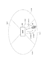
以下において、第1実施形態に係る無線通信システムの構成について、図面を参照しながら説明する。図1は、第1実施形態に係る無線通信システムを示す図である。図1に示すように、無線通信システムは、無線端末10と、基地局100とを有する。
[First Embodiment]
(Configuration of wireless communication system)
Hereinafter, the configuration of the wireless communication system according to the first embodiment will be described with reference to the drawings. FIG. 1 is a diagram illustrating a wireless communication system according to the first embodiment. As shown in FIG. 1, the wireless communication system includes a
無線端末10は、上り方向ユーザデータを基地局100に送信する。具体的には、無線端末10は、無線制御装置が無線リソースの割り当てなどを行う枠組みにおいて、個別物理データチャネル(DPDCH;Dedicated Physical Data Channel)を介して上り方向ユーザデータを基地局100に送信する。なお、無線制御装置が無線リソースの割り当てなどを行う枠組みは、R99(Release99)などと称されることもある。
The
無線端末10は、基地局100が無線リソースの割り当てなどを行う枠組みにおいて、エンハンスド個別物理データチャネル(E−DPDCH;Enhanced Dedicated Physical Data Channel)を介して上り方向ユーザデータを基地局100に送信する。なお、基地局100が無線リソースの割り当てなどを行う枠組みは、HSUPA(High Speed Uplink Packet Access)、EUL(Enhanced Uplink)などと称されることもある。
The
ここで、上り方向ユーザデータは、1TTI(Transmission Time Interval)、すなわち、プロセス(HARQ process)単位でブロック化される。各ブロック(MAC−e PDU)は、無線端末10に割り当てられたプロセス(以下、アクティブプロセス)を用いて送信される。
Here, the uplink user data is blocked in units of 1 TTI (Transmission Time Interval), that is, a process (HARQ process). Each block (MAC-e PDU) is transmitted using a process (hereinafter referred to as an active process) assigned to the
また、所定数のプロセス(プロセス#1〜プロセス#n)は、1サイクル(HARQ RTT)を構成しており、サイクル単位で繰り返される。なお、1サイクルに含まれるプロセス数は、TTI長に応じて定められている。例えば、TTI長が2msである場合には、1サイクル内に含まれるプロセス数は“8”である。TTI長が10msである場合には、1サイクル内に含まれるプロセス数は“4”である。 Further, a predetermined number of processes (process # 1 to process #n) constitute one cycle (HARQ RTT) and are repeated in units of cycles. Note that the number of processes included in one cycle is determined according to the TTI length. For example, when the TTI length is 2 ms, the number of processes included in one cycle is “8”. When the TTI length is 10 ms, the number of processes included in one cycle is “4”.
なお、無線端末10は、DPDCHやE−DPDCHなどのデータチャネルを介して上り方向ユーザデータを送信するだけではなくて、DPCCH(Dedicated Physical Control Channel)やE−DPCCH(Enhanced Dedicated Physical Control Channel)などを介して上り方向制御データを送信する。
The
基地局100は、複数のセル(セルA〜セルD)を有しており、各セルは、自セルに在圏する無線端末10と通信を行う。各セルは、サービングセルとして機能するケースと非サービングセルとして機能するケースとがある。
The
なお、「セル」は、基本的に、無線端末10と通信を行う機能を示す用語として用いることに留意すべきである。また、「セル」は、無線端末10が在圏するエリアを示す用語として用いる場合もあることに留意すべきである。
It should be noted that “cell” is basically used as a term indicating a function of performing communication with the
例えば、図1において、セルAに設けられたEULスケジューラの指示に従って無線端末10が通信を行っているケース(すなわち、セルAからE−AGCHを介して受信するAGに従って通信を行っているケース)について考える。このようなケースでは、セルAは、無線端末10にとってサービングセルであり、セルB〜セルDは、無線端末10にとって非サービングセルである。一方で、無線端末10は、セルAにとってサービング端末であり、セルB〜セルDにとって非サービング端末である。
For example, in FIG. 1, a case where the
基地局100は、DPDCHやE−DPDCHなどのデータチャネルを介して上り方向ユーザデータを無線端末10から受信する。一方、基地局100は、E−DPDCHを介して送信される上り方向ユーザデータの伝送速度を制御するための制御データを無線端末10に送信する。なお、制御データは、伝送速度を直接的に指定するための絶対伝送速度制御データ(AG;Absolute Grant)、伝送速度を相対的に指定するための相対伝送速度制御データ(RG;Relative Grant)を含む。
The
ここで、無線端末10は、送信電力比と伝送速度とを対応付けるテーブルを有している。送信電力比は、E−DPDCHの送信電力とDPCCHの送信電力との比(E−DPDCH/DPCCH)である。伝送速度は、TBS;Transport Block Sizeによって表される。
Here, the
以下においては、無線端末10に許容される送信電力比をSG(Serving Grant)と称する。なお、送信電力比と伝送速度とは1対1で対応付けられているため、SG(Serving Grant)は、無線端末10に許容される送信電力比を示す用語だけではなく、無線端末10に許容される伝送速度を示す用語として考えてもよい。
Hereinafter, the transmission power ratio allowed for the
絶対伝送速度制御データ(AG)は、無線端末10に許容される送信電力比(E−DPDCH/DPCCH)を直接的に指定するデータ(Index)である(3GPP TS25.212 Ver.7.5.0 4.10.1A.1 “Information field mapping of the Absolute Grant Value”を参照)。 The absolute transmission rate control data (AG) is data (Index) that directly specifies the transmission power ratio (E-DPDCH / DPCCH) allowed for the radio terminal 10 (3GPP TS25.212 Ver.7.5. 0 4.10.1 A.1 “Information field mapping of the absolute grant value”).
このように、絶対伝送速度制御データ(AG)は、現在の伝送速度に依拠せずに、伝送速度の値を直接的に指示するコマンドである。 As described above, the absolute transmission rate control data (AG) is a command that directly indicates the value of the transmission rate without depending on the current transmission rate.
相対伝送速度制御データ(RG)は、無線端末10に許容される送信電力比(E−DPDCH/DPCCH)を相対的に指定するデータ(“Up”、“Down”、“Hold”)である(3GPP TS25.321 Ver.7.5.0 9.2.5.2.1 “Relative Grants”を参照)。 The relative transmission rate control data (RG) is data (“Up”, “Down”, “Hold”) that relatively specifies the transmission power ratio (E-DPDCH / DPCCH) allowed for the radio terminal 10 ( 3GPP TS 25.321 Ver. 7.5.0 9.2.5.2.1 (see “Relativity Grants”).
このように、相対伝送速度制御データ(RG)は、現在の伝送速度を相対的に制御するコマンドである。具体的には、現在の伝送速度の増加を指示する増加コマンド“Up”、現在の伝送速度の維持を指示する維持コマンド“Hold”、現在の伝送速度の減少を指示する減少コマンド“Down”を含む。なお、増加コマンドは、所定増加幅の増加を指示するコマンドであり、減少コマンドは、所定減少幅の減少を指示するコマンドである。所定増加幅は、所定減少幅と同じであってもよく、所定減少幅よりも小さくてもよい。 Thus, the relative transmission rate control data (RG) is a command for relatively controlling the current transmission rate. Specifically, an increase command “Up” for instructing an increase in the current transmission rate, a maintenance command “Hold” instructing to maintain the current transmission rate, and a decrease command “Down” instructing a decrease in the current transmission rate are provided. Including. The increase command is a command for instructing an increase in the predetermined increase width, and the decrease command is a command for instructing a decrease in the predetermined decrease width. The predetermined increase width may be the same as the predetermined decrease width, or may be smaller than the predetermined decrease width.
無線端末10は、基地局100から受信したAG又はRGに応じてSGを更新する(3GPP TS25.321 Ver.7.5.0 11.8.1.3 “Serving Grant Update”を参照)。続いて、無線端末10は、送信電力比と伝送速度とを対応付けるテーブルを参照して、SGに対応する伝送速度(すなわち、TBS)を決定する(3GPP TS25.321 Ver.7.5.0 11.8.1.4 “E−TFC Selection”を参照)。
The
基地局100は、絶対伝送速度制御チャネル(E−AGCH;E−DCH Absolute Grant Channel)を介してAGを無線端末に送信する。基地局100は、相対伝送速度制御チャネル(E−RGCH;E−DCH Relative Grant Channel)を介してRGを無線端末に送信する。
The
例えば、サービングセル(ここでは、セルA)は、E−AGCHを介してAGを無線端末に送信し、E−RGCHを介してRGを無線端末に送信する。一方で、非サービングセル(ここでは、セルB)は、E−AGCHを介してAGを無線端末に送信せずに、E−RGCHを介してRGを無線端末に送信する。 For example, the serving cell (here, cell A) transmits AG to the radio terminal via E-AGCH and transmits RG to the radio terminal via E-RGCH. On the other hand, the non-serving cell (here, cell B) transmits RG to the wireless terminal via E-RGCH without transmitting AG to the wireless terminal via E-AGCH.
なお、図1では、説明を簡略化するために、R99で用いられるチャネル(DPDCHやDPCCHなど)が省略されているに過ぎないことに留意すべきである。 It should be noted that in FIG. 1, channels (DPDCH, DPCCH, etc.) used in R99 are merely omitted for the sake of simplicity.
また、実際には、各セルに多数の無線端末10が存在していることに留意すべきである。例えば、セルB〜セルDにとってサービング端末である無線端末10が存在している。すなわち、セルAにとって非サービング端末である無線端末10が存在している。一方で、セルAにとってサービング端末である無線端末10が図1に示す無線端末10以外にも存在している。すなわち、セルB〜セルDにとって非サービング端末である無線端末10が図1に示す無線端末10以外にも存在している。
In addition, it should be noted that there are actually a large number of
なお、無線端末10がサービングセルとして用いるセルは、1セルに限定されるものではなく、複数セルであってもよいことに留意すべきである。
Note that the cell used as the serving cell by the
(基地局の構成)
以下において、第1実施形態に係る基地局の構成について、図面を参照しながら説明する。図2は、第1実施形態に係る基地局100を示すブロック図である。
(Base station configuration)
Hereinafter, the configuration of the base station according to the first embodiment will be described with reference to the drawings. FIG. 2 is a block diagram showing the
図2に示すように、基地局100は、通信部110と、セルA機能部120と、セルB機能部130と、セルC機能部140と、セルD機能部150とを有する。
As illustrated in FIG. 2, the
通信部110は、セルA〜セルD内に在圏する無線端末10と通信を行う。具体的には、通信部110は、DPDCHやE−DPDCHなどのデータチャネルを介して上り方向ユーザデータを無線端末10から受信する。通信部110は、DPCCHやE−DPCCHなどの制御チャネルを介して上り方向制御データを無線端末10から受信する。一方で、通信部110は、E−AGCHやE−RGCHなどの制御チャネルを介して制御データ(AGやRG)を無線端末10に送信する。
The
なお、通信部110は、基地局100を管理する上位局(無線制御装置や交換機など)とも通信を行う。
Note that the
セルA機能部120は、セルAに在圏する無線端末10にとってサービングセルとして機能する。一方で、セルA機能部120は、セルB〜セルDに在圏する無線端末10にとって非サービングセルとして機能する。
The cell
セルB機能部130は、セルBに在圏する無線端末10にとってサービングセルとして機能する。一方で、セルB機能部130は、セルA、セルC及びセルDに在圏する無線端末10にとって非サービングセルとして機能する。
The cell
セルC機能部140は、セルCに在圏する無線端末10にとってサービングセルとして機能する。一方で、セルC機能部140は、セルA、セルB及びセルDに在圏する無線端末10にとって非サービングセルとして機能する。
The cell C function unit 140 functions as a serving cell for the
セルD機能部150は、セルDに在圏する無線端末10にとってサービングセルとして機能する。一方で、セルD機能部150は、セルA〜セルCに在圏する無線端末10にとって非サービングセルとして機能する。
The cell D function unit 150 functions as a serving cell for the
なお、非サービングセルとして機能するセルの詳細については後述する(図3を参照)。同様に、サービングセルとして機能するセルの詳細については後述する(図5を参照)。また、第1実施形態では、セルB(セルB機能部130)が非サービングセルとして機能するケース、セルA(セルA機能部120)がサービングセルとして機能するケースについて例示する。 Details of the cell functioning as a non-serving cell will be described later (see FIG. 3). Similarly, details of the cell functioning as a serving cell will be described later (see FIG. 5). Moreover, in 1st Embodiment, the case where the cell B (cell B functional part 130) functions as a non-serving cell and the case where the cell A (cell A functional part 120) functions as a serving cell are illustrated.
(非サービングセルとして機能するセルの構成)
以下において、第1実施形態に係る非サービングセルとして機能するセルの構成について、図面を参照しながら説明する。図3は、第1実施形態に係る非サービングセルとして機能するセルB(セルB機能部130)を示すブロック図である。上述したように、セルB機能部130(セルB)は、セルA、セルC又はセルDに在圏する無線端末10(すなわち、セルA、セルC又はセルDをサービングセルとして用いる無線端末10)に対して非サービングセルとして機能する。
(Configuration of cells that function as non-serving cells)
Hereinafter, the configuration of a cell that functions as a non-serving cell according to the first embodiment will be described with reference to the drawings. FIG. 3 is a block diagram showing a cell B (cell B functional unit 130) functioning as a non-serving cell according to the first embodiment. As described above, the cell B functional unit 130 (cell B) is the
図3に示すように、非サービングセルとして機能するセルB機能部130は、干渉測定部131と、カウンタ132と、RG制御部133とを有する。
As illustrated in FIG. 3, the cell B
干渉測定部131は、セルBに在圏する無線端末10(サービング端末)から受信する各種データの受信電力、及び、セルB以外の他セルに在圏する無線端末10(非サービング端末)から受信する各種データの干渉電力を測定する。セルB以外の他セルは、セルA、セルC及びセルDだけではなくて、基地局100に隣接する他の基地局が有するセルを含む。
The
具体的には、図4に示すように、干渉測定部131は、雑音電力、受信電力(R99)、干渉電力(R99)、受信電力(サービング)及び干渉電力(非サービング)を測定する。
Specifically, as illustrated in FIG. 4, the
受信電力(R99)は、セルBに在圏する無線端末10からDPDCHを介して受信する上り方向ユーザデータの受信電力である。干渉電力(R99)は、セルB以外の他セルに在圏する無線端末10からDPDCHを介して受信する上り方向ユーザデータの受信電力である。
The received power (R99) is the received power of the uplink user data received from the
受信電力(サービング)は、セルBに在圏する無線端末10(サービング端末)からE−DPDCHを介して受信する上り方向ユーザデータの受信電力である。干渉電力(非サービング)は、セルB以外の他セルに在圏する無線端末10(非サービング端末)からE−DPDCHを介して受信する上り方向ユーザデータの受信電力である。 The received power (serving) is the received power of the uplink user data received via the E-DPDCH from the radio terminal 10 (serving terminal) located in the cell B. The interference power (non-serving) is the reception power of the uplink user data received via the E-DPDCH from the radio terminal 10 (non-serving terminal) located in a cell other than the cell B.
カウンタ132は、ガードカウンタとトリガカウンタとを含む。ガードカウンタは、セルB以外の他セルをサービングセルとして用いる無線端末10(非サービング端末)にRGを送信してから経過した時間である経過時間をカウントする。トリガカウンタは、セルBにおける受信電力が所定条件を満たす状態の継続時間をカウントする。
The
具体的には、ガードカウンタは、サブフレーム周期(2msec)毎にカウントアップされるカウンタである。ガードカウンタのカウント値は、非サービング端末にRGを送信した際にリセットされる。ガードカウンタのカウント値は、サブフレーム間で引き継がれる。なお、ガードカウンタは、セル毎に設けられており、経過時間をセル毎にカウントする。 Specifically, the guard counter is a counter that is counted up every subframe period (2 msec). The count value of the guard counter is reset when RG is transmitted to the non-serving terminal. The count value of the guard counter is inherited between subframes. The guard counter is provided for each cell, and counts the elapsed time for each cell.
トリガカウンタは、サブフレーム周期(2msec)毎にカウントアップされるカウンタである。トリガカウンタのカウント値は、セルBにおける受信電力が所定条件を満たさなくなった際にリセットされる。トリガカウンタのカウント値は、サブフレーム間で引き継がれる。 The trigger counter is a counter that is counted up every subframe period (2 msec). The count value of the trigger counter is reset when the reception power in the cell B does not satisfy the predetermined condition. The count value of the trigger counter is inherited between subframes.
ここで、所定条件とは、(1)“RTWP閾値≧目標RTWP−測定RTWP”、(2)“所定干渉電力≦干渉電力(非サービング)”である。 Here, the predetermined conditions are (1) “RTWP threshold ≧ target RTWP−measured RTWP” and (2) “predetermined interference power ≦ interference power (non-serving)”.
総受信電力(RTWP;Received Total Wideband Power)は、雑音電力、受信電力(R99)、干渉電力(R99)、受信電力(サービング)及び干渉電力(非サービング)の合計である。目標RTWPは、セルにおいて目標とされるRTWPである。測定RTWPは、セルにおいて測定されたRTWPである。RTWP閾値は、測定RTWPが目標RTWPの近傍であるか否かを判定するための閾値である。 Total received power (RTWP) is the sum of noise power, received power (R99), interference power (R99), received power (serving), and interference power (non-serving). The target RTWP is the RTWP targeted in the cell. The measured RTWP is the RTWP measured in the cell. The RTWP threshold value is a threshold value for determining whether or not the measured RTWP is in the vicinity of the target RTWP.
RG制御部133は、他セルをサービングセルとして用いる無線端末10(非サービング端末)からE−DPDCHを介して受信する上り方向ユーザデータの減少を指示するRGの送信間隔を制御する。具体的には、RG制御部133は、以下に示す動作を行う。
The
第1に、RG制御部133は、セルBにおける受信電力が所定条件を満たすか否かを判定する。具体的には、RG制御部133は、“RTWP閾値≧目標RTWP−測定RTWP”が満たされているか否かを判定する。RG制御部133は、“所定干渉電力≦干渉電力(非サービング)”が満たされているか否かを判定する。
First, the
ここで、所定干渉閾値は、予め定められた固定値であってもよく、受信電力(サービング)と干渉電力(非サービング)との比率によって定められる値であってもよい。 Here, the predetermined interference threshold value may be a predetermined fixed value, or may be a value determined by a ratio between received power (serving) and interference power (non-serving).
例えば、所定干渉閾値を“Th”、干渉電力(非サービング)を“I”、受信電力(サービング)を“S”で表したケースについて考える。 For example, consider a case where a predetermined interference threshold is represented by “Th”, interference power (non-serving) is represented by “I”, and received power (serving) is represented by “S”.
このようなケースにおいて、所定干渉閾値“Th”が予め定められた値である場合には、RG制御部133は、“I”が“Th”を超えているか否かを判定する。
In such a case, when the predetermined interference threshold “Th” is a predetermined value, the
所定干渉閾値“Th”が“I/S”で定められた値である場合には、RG制御部133は、“I”が“Th×S”を超えているか否かを判定する。逆に、所定干渉閾値“Th”が“S/I”で定められた値である場合には、RG制御部133は、“I”が“S/Th”を超えているか否かを判定する。
When the predetermined interference threshold “Th” is a value determined by “I / S”, the
所定干渉閾値“Th”が“I/S+I”で定められた値である場合には、RG制御部133は、“I”が“Th×(S+I)”を超えているか否かを判定する。逆に、所定干渉閾値“Th”が“S+I/I”で定められた値である場合には、RG制御部133は、“I”が“(S+I)/Th”を超えているか否かを判定する。
When the predetermined interference threshold “Th” is a value determined by “I / S + I”, the
第2に、RG制御部133は、ガードカウンタのカウント値がガード閾値よりも小さいか否かを判定する。ガード閾値は、他セルをサービングセルとして用いる無線端末10(非サービング端末)にRGを連続的に送信すべきではない時間(所定非送信時間)を定める閾値である。
Secondly, the
第3に、RG制御部133は、トリガカウンタのカウント値がトリガ閾値よりも小さいか否かを判定する。トリガ閾値は、上述した所定条件が満たされた場合に、他セルをサービングセルとして用いる無線端末10(非サービング端末)に対するRGの送信を保留する時間(所定保留時間)を定める閾値である。
Thirdly, the
第4に、RG制御部133は、ガードカウンタのカウント値がガード閾値よりも大きく、トリガカウンタのカウント値がトリガ閾値よりも大きい場合に、他セルをサービングセルとして用いる無線端末10(非サービング端末)に対して、E−RGCHを介してRGを送信する。なお、RGは、維持コマンド“Hold”又は減少コマンド“Down”である。上述したように、減少コマンド“Down”は、所定減少幅の減少を指示するコマンドである。なお、RG制御部133は、増加コマンド“Up”を非サービング端末に送信しないことに留意すべきである。
Fourth, the
(サービングセルとして機能するセルの構成)
以下において、第1実施形態に係るサービングセルとして機能するセルの構成について、図面を参照しながら説明する。図5は、第1実施形態に係るサービングセルとして機能するセルA(セルA機能部120)を示すブロック図である。上述したように、セルA機能部120(セルA)は、セルAに在圏する無線端末10(すなわち、セルAをサービングセルとして用いる無線端末10)に対してサービングセルとして機能する。
(Configuration of cell functioning as serving cell)
Hereinafter, the configuration of a cell functioning as a serving cell according to the first embodiment will be described with reference to the drawings. FIG. 5 is a block diagram showing a cell A (cell A functional unit 120) functioning as a serving cell according to the first embodiment. As described above, the cell A function unit 120 (cell A) functions as a serving cell for the
図5に示すように、サービングセルとして機能するセルA機能部120は、セルAをサービングセルとして用いる無線端末10に対する無線リソースの割り当てなどを行うスケジューリング部120aを有する。
As illustrated in FIG. 5, the cell
スケジューリング部120aは、AG制御部121と、RG制御部122と、再送制御部123と、送信スロット割当部124とを有する。スケジューリング部120aは、MAC−e(Media Access Control Enhanced)層で動作する。
The scheduling unit 120a includes an
AG制御部121は、セルAをサービングセルとして用いる無線端末10(サービング端末)に対して、E−AGCHを介してAGを送信する。なお、AGは、現在の伝送速度に依拠せずに、伝送速度の値を直接的に指示するコマンドである。
AG control
RG制御部122は、セルAをサービングセルとして用いる無線端末10(サービング端末)に対して、E−RGCHを介してRGを送信する。なお、RGは、増加コマンド“Up”、維持コマンド“Hold”、減少コマンド“Down”である。上述したように、増加コマンド“Up”は、所定増加幅の増加を指示するコマンドであり、減少コマンド“Down”は、所定減少幅の減少を指示するコマンドである。
The
再送制御部123は、上り方向ユーザデータに誤りが生じているか否かをブロック毎に判定する。続いて、再送制御部123は、誤りを有するブロック(以下、誤りブロック)の再送を無線端末10に要求する。再送制御技術は、無線端末10から初めて送信されたブロック(以下、送信ブロック)と無線端末10から再送されたブロック(以下、再送ブロック)とを合成するHARQ(Hybrid Automatic Repeat Request)技術である。
The
送信スロット割当部124は、E−DPDCHを介して送信する上り方向ユーザデータ(ブロック)の送信に用いる送信スロット(すなわち、TTI)を無線端末10に割り当てる。なお、無線端末10は、送信スロット割当部124によって割り当てられた送信スロットで送信ブロックや再送ブロックを基地局100に送信する。
The transmission
(非サービングセルとして機能するセルの動作)
以下において、第1実施形態に係る非サービングセルとして機能するセルの動作について、図面を参照しながら説明する。図6は、第1実施形態に係る非サービングセルとして機能するセルB(セルB機能部130)の動作を示すフロー図である。なお、図6に示す動作は、サブフレーム周期(2msec)毎に繰り返されることに留意すべきである。
(Operation of cells functioning as non-serving cells)
Hereinafter, an operation of a cell functioning as a non-serving cell according to the first embodiment will be described with reference to the drawings. FIG. 6 is a flowchart showing the operation of the cell B (cell B functional unit 130) functioning as a non-serving cell according to the first embodiment. It should be noted that the operation shown in FIG. 6 is repeated every subframe period (2 msec).
図6に示すように、ステップ10において、セルB機能部130は、ガードカウンタのカウントアップを行う。
As shown in FIG. 6, in
ステップ11において、セルB機能部130は、目標RTWP−測定RTWPがRTWP閾値よりも大きいか否かを判定する。すなわち、セルB機能部130は、“RTWP閾値≧目標RTWP−測定RTWP”が満たされているか否かを判定する。
In step 11, the cell B
セルB機能部130は、目標RTWP−測定RTWPがRTWP閾値よりも大きい場合、すなわち、“RTWP閾値≧目標RTWP−測定RTWP”が満たされていない場合には、ステップ18の処理に移る。一方で、セルB機能部130は、目標RTWP−測定RTWPがRTWP閾値よりも大きくない場合、すなわち、“RTWP閾値≧目標RTWP−測定RTWP”が満たされている場合には、ステップ12の処理に移る。
When the target RTWP−measured RTWP is larger than the RTWP threshold, that is, when “RTWP threshold ≧ target RTWP−measured RTWP” is not satisfied, the cell B
ステップ12において、セルB機能部130は、干渉電力(非サービング)が所定干渉閾値よりも小さいか否かを判定する。すなわち、セルB機能部130は、“所定干渉電力≦干渉電力(非サービング)”が満たされているか否かを判定する。
In Step 12, the cell B
セルB機能部130は、干渉電力(非サービング)が所定干渉閾値よりも小さい場合、すなわち、“所定干渉電力≦干渉電力(非サービング)”が満たされていない場合には、ステップ18の処理に移る。一方で、セルB機能部130は、干渉電力(非サービング)が所定干渉閾値よりも小さくない場合、すなわち、“所定干渉電力≦干渉電力(非サービング)”が満たされている場合には、ステップ13の処理に移る。
When the interference power (non-serving) is smaller than the predetermined interference threshold, that is, when “predetermined interference power ≦ interference power (non-serving)” is not satisfied, the cell B
ステップ13において、セルB機能部130は、トリガカウンタのカウントアップを行う。
In step 13, the cell B
ステップ14において、セルB機能部130は、トリガカウンタのカウント値がトリガ閾値よりも小さいか否かを判定する。セルB機能部130は、トリガカウンタのカウント値がトリガ閾値よりも小さい場合には、一連の処理を終了する。一方で、セルB機能部130は、トリガカウンタのカウント値がトリガ閾値よりも小さくない場合には、ステップ15の処理に移る。
In step 14, the cell B
ステップ15において、セルB機能部130は、ガードカウンタのカウント値がガード閾値よりも小さい場合には、一連の処理を終了する。一方で、セルB機能部130は、ガードカウンタのカウント値がガード閾値よりも小さくない場合には、ステップ16の処理に移る。
In step 15, when the count value of the guard counter is smaller than the guard threshold value, the cell B
ステップ16において、セルB機能部130は、他セルをサービングセルとして用いる無線端末10(非サービング端末)に対して、E−RGCHを介してRGを送信する。
In Step 16, the cell B
ステップ17において、セルB機能部130は、ガードカウンタをリセットする。ステップ18において、セルB機能部130は、トリガカウンタをリセットする。
In step 17, the cell B
(作用及び効果)
第1実施形態では、RG制御部133は、他セルをサービングセルとして用いる無線端末10に送信するRG(減少コマンド)の送信間隔を制御する。従って、非サービングセルが送信するRG(減少コマンド)によって、上り方向ユーザデータの伝送速度の増減が頻繁に生じることが抑制される。なお、RG(減少コマンド)の送信によって、非サービングセルで生じる干渉電力が抑制されることは勿論である。
(Function and effect)
In the first embodiment, the
具体的には、RG制御部133は、ガードカウンタのカウンタ値がガード閾値よりも小さい場合にRGの送信を規制する。従って、RGが連続的に送信されることによって、上り方向ユーザデータの増減が頻繁に生じることが抑制される。
Specifically, the
RG制御部133は、トリガカウンタのカウンタ値がトリガ閾値よりも小さい場合にRGの送信を保留する。トリガカウンタは、セルBにおける受信電力が所定条件を満たす状態の継続時間をカウントする。所定条件は、(1)“RTWP閾値≧目標RTWP−測定RTWP”、(2)“所定干渉電力≦干渉電力(非サービング)”である。
The
すなわち、RG制御部133は、“RTWP閾値≧目標RTWP−測定RTWP”が満たされてすぐにRGの送信を行わずに、トリガカウンタのカウンタ値がトリガ閾値以上となるまでRGの送信を保留する。従って、測定RTWPが目標RTWPの近傍である場合に、RTWPが頻繁に増減することを抑制することができる。
In other words, the
RG制御部133は、“所定干渉電力≦干渉電力(非サービング)”が満たされてすぐにRGの送信を行わずに、トリガカウンタのカウンタ値がトリガ閾値以上となるまでRGの送信を保留する。従って、干渉電力(非サービング)が所定干渉電力以上となったことに起因して、RGの送信が頻繁に生じることを抑制することができる。
The
[第2実施形態]
以下において、第2実施形態について図面を参照しながら説明する。以下においては、上述した第1実施形態と第2実施形態との相違点について主として説明する。
[Second Embodiment]
The second embodiment will be described below with reference to the drawings. In the following, differences between the first embodiment and the second embodiment described above will be mainly described.
上述した第1実施形態では特に触れていないが、第2実施形態では、非サービングセルとして機能するセルB機能部130は、上り方向ユーザデータ(無線リンク)に割り当てられた優先度クラス(Priority Class)に応じて、他セルをサービングセルとして用いる無線端末10に送信するRGの送信間隔を制御する。
Although not particularly mentioned in the first embodiment described above, in the second embodiment, the cell B
(非サービングセルとして機能するセルの構成)
以下において、第2実施形態に係る非サービングセルとして機能するセルの構成について、図面を参照しながら説明する。図7は、第2実施形態に係る非サービングセルとして機能するセルB(セルB機能部130)を示すブロック図である。なお、図7では、上述した図3と同様の構成について同様の符号を付していることに留意すべきである。
(Configuration of cells that function as non-serving cells)
Hereinafter, the configuration of a cell functioning as a non-serving cell according to the second embodiment will be described with reference to the drawings. FIG. 7 is a block diagram showing a cell B (cell B functional unit 130) functioning as a non-serving cell according to the second embodiment. In FIG. 7, it should be noted that the same components as those in FIG.
図7に示すように、非サービングセルとして機能するセルB機能部130は、図3に示した構成に加えて、記憶部134を有する。
As illustrated in FIG. 7, the cell B
記憶部134は、図8に示すRG送信対象順位テーブルを記憶する。RG送信対象順位テーブルでは、図8に示すように、“グループNo.”と、“優先度クラス”と、“判定値”と、“無線リンクの有無”とが対応付けられている。
The
“グループNo.”は、RGの送信対象とすべき無線リンクを検索する順位(検索順位)毎に分類されたグループを識別する番号である。後述するように、RGの送信対象とすべき無線リンクはグループ毎に検索される。 “Group No.” is a number for identifying a group classified for each rank (search rank) for searching for a radio link to be transmitted by RG. As will be described later, a radio link to be transmitted by RG is searched for each group.
具体的には、各無線リンクは、グループ#1〜グループ#nに分類されている。グループNo.が小さいグループの検索順位は、グループNo.が大きいグループの検索順位よりも高い。 Specifically, each wireless link is classified into group # 1 to group #n. Group No. The search order of a group with a small number is the group number. Is higher than the search ranking of large groups.
なお、RGの送信対象とすべき無線リンクを検索するグループ(ターゲットグループ)は、ターゲットグループ数に応じて、グループNo.が小さい順に選択される。ターゲットグループ数は、同一の他セルをサービングセルとして用いる無線端末10にRGを送信した回数が最大送信回数(例えば、3回)となった際に更新される。
Note that a group (target group) for searching for a radio link to be transmitted by RG is a group No. corresponding to the number of target groups. Are selected in ascending order. The number of target groups is updated when the number of times of transmitting RG to the
“優先度クラス(Priority Class)”は、上り方向ユーザデータ(無線リンク)に割り当てられた優先度である。第2実施形態では、優先度クラスの種類は、クラス0〜クラス15の16種類である。ここでは、優先度クラスの値が大きくなるほど、上り方向ユーザデータ(無線リンク)の優先度が高い。 “Priority class” is a priority assigned to uplink user data (wireless link). In the second embodiment, there are 16 types of priority classes, class 0 to class 15. Here, the higher the priority class value, the higher the priority of the uplink user data (radio link).
“判定値”は、優先度クラスがグループに含まれるか否かを示す値である。“TRUE”は、優先度クラスがグループに含まれることを示す。“FALSE”は、優先度クラスがグループに含まれないことを示す。例えば、グループ#1を例に挙げると、クラス0及びクラス1は、グループ#1に含まれており、クラス15は、グループ#1に含まれていない。 The “determination value” is a value indicating whether or not the priority class is included in the group. “TRUE” indicates that the priority class is included in the group. “FALSE” indicates that the priority class is not included in the group. For example, taking group # 1 as an example, class 0 and class 1 are included in group # 1, and class 15 is not included in group # 1.
ここでは、優先度クラスが低い無線リンク(上り方向ユーザデータ)に対応するRGの送信頻度が、優先度クラスが高い無線リンクに対応するRGの送信頻度よりも高くなるように、各グループに含まれる優先度クラスが設定されている。具体的には、グループNo.が小さいグループには、優先度クラスが低い無線リンクが含まれており、グループNo.が大きいグループには、優先度クラスが高い無線リンクが含まれる。 Here, it is included in each group so that the transmission frequency of RG corresponding to a radio link (uplink user data) with a low priority class is higher than the transmission frequency of RG corresponding to a radio link with a high priority class. Priority class to be set. Specifically, the group No. The group having a smaller priority class includes a radio link having a lower priority class. A group having a larger value includes a radio link having a higher priority class.
但し、グループに含まれる優先度クラスは任意に設定することが可能であることは勿論である。 However, as a matter of course, the priority class included in the group can be arbitrarily set.
“無線リンクの有無”は、セルBを非サービングセルとして用いる無線端末10(非サービング端末)とセルBとの間に設定された無線リンクについて、各優先度クラスが割り当てられた無線リンクが存在するか否かを示している。“無”は、各優先度クラスが割り当てられた無線リンクが存在しないことを示す。“有”は、各優先度クラスが割り当てられた無線リンクが存在することを示す。 “Presence / absence of radio link” indicates that there is a radio link to which each priority class is assigned for a radio link set between the radio terminal 10 (non-serving terminal) using the cell B as a non-serving cell and the cell B. Indicates whether or not. “None” indicates that there is no radio link to which each priority class is assigned. “Present” indicates that there is a radio link to which each priority class is assigned.
なお、“優先度クラス”や“判定値”は、予め設定される設定値である。“無線リンクの有無”は、TTI周期、サブフレーム周期又は任意の周期で更新される測定値である。 Note that “priority class” and “determination value” are preset values. “Presence / absence of radio link” is a measurement value updated in a TTI period, a subframe period, or an arbitrary period.
RG制御部133は、RG送信対象順位テーブルを参照して、RGの送信対象とすべき無線リンクを検索する。具体的には、RG制御部133は、ターゲットグループ数に相当するターゲットグループをグループNo.が小さい順に選択する。続いて、RG制御部133は、ターゲットグループに含まれる優先度クラスを有する無線リンクに対応するRGの送信を決定する。
The
なお、RG制御部133は、同一の他セルをサービングセルとして用いる無線端末10にRGを送信した回数が最大送信回数(例えば、3回)となった際に、ターゲットグループ数に“1”を加算する。
The
ここで、ターゲットグループ数に“1”が加算された場合に、ターゲットグループは、グループNo.が小さい順に再び選択される。すなわち、グループNo.が小さいグループは、ターゲットグループとして選択される頻度が高い。従って、グループNo.が小さいグループに含まれる優先度クラスを有する無線リンクに対応するRGの送信頻度も高い。 Here, when “1” is added to the number of target groups, the target group is a group number. Are selected again in ascending order. That is, the group No. A group having a small value is frequently selected as a target group. Therefore, the group No. The transmission frequency of RG corresponding to a radio link having a priority class included in a small group is also high.
また、上述したように、グループNo.が小さいグループには、優先度クラスが低い無線リンクが含まれており、グループNo.が大きいグループには、優先度クラスが高い無線リンクが含まれる。従って、優先度クラスが低い無線リンクに対応するRGの送信頻度は、優先度クラスが高い無線リンクに対応するRGの送信頻度よりも高い。 As described above, the group No. The group having a smaller priority class includes a radio link having a lower priority class. A group having a larger value includes a radio link having a higher priority class. Therefore, the transmission frequency of RG corresponding to a radio link with a low priority class is higher than the transmission frequency of RG corresponding to a radio link with a high priority class.
このように、RG制御部133は、上り方向ユーザデータ(無線リンク)に割り当てられた優先度クラスに応じて、他セルをサービングセルとして用いる無線端末10に送信するRGの送信間隔(送信頻度)を制御する。
In this way, the
具体的には、RG制御部133は、優先度クラスが高い無線リンクに対応するRGの送信間隔が、優先度クラスが低い無線リンクに対応するRGの送信間隔よりも長くなるように、RGの送信間隔を制御する。
Specifically, the
(非サービングセルとして機能するセルの動作)
以下において、第2実施形態に係る非サービングセルとして機能するセルの動作について、図面を参照しながら説明する。図9は、第2実施形態に係る非サービングセルとして機能するセルB(セルB機能部130)の動作を示すフロー図である。なお、図9の動作は、図6に示したステップ16の処理の詳細である。
(Operation of cells functioning as non-serving cells)
Hereinafter, an operation of a cell functioning as a non-serving cell according to the second embodiment will be described with reference to the drawings. FIG. 9 is a flowchart showing an operation of the cell B (cell B functional unit 130) functioning as a non-serving cell according to the second embodiment. The operation in FIG. 9 is the details of the processing in step 16 shown in FIG.
図9に示すように、ステップ21において、セルB機能部130は、ターゲットグループ数をセットする。上述したように、同一の他セルをサービングセルとして用いる無線端末10にRGを送信した回数が最大送信回数(例えば、3回)となった際に、ターゲットグループ数に“1”が加算される。
As shown in FIG. 9, in step 21, the cell B
なお、第2実施形態では、上述したように、ターゲットグループは、グループNo.が小さい順に選択される。例えば、ターゲットグループ数が“2”である場合には、ターゲットグループは、グループ#1及びグループ#2である。 In the second embodiment, as described above, the target group is the group number. Are selected in ascending order. For example, when the number of target groups is “2”, the target groups are group # 1 and group # 2.
ステップ22a〜ステップ22bにおいて、セルB機能部130は、RG送信対象順位テーブル内において、RGの送信対象とすべき無線リンクの有無をターゲットグループ毎に検索する処理を行う。なお、ターゲットグループは、ステップ21でセットされたターゲットグループ数に応じて選択される。
In Step 22a to Step 22b, the cell B
ステップ23において、セルB機能部130は、検索対象のターゲットグループ(gi)をセットする。例えば、ターゲットグループ(gi)の初期値は、ステップ21でセットされたターゲットグループ数である。
In step 23, the cell B
ステップ24において、セルB機能部130は、検索対象の優先度クラス(c)をセットする。例えば、優先度クラス(c)の初期値は“0”である。
In step 24, the cell B
ステップ25a〜ステップ25bにおいて、セルB機能部130は、ターゲットグループ(gi)内において、RGの送信対象とすべき無線リンクの有無を優先度クラス毎に検索する処理を行う。
In Step 25a to Step 25b, the cell B
ステップ26において、セルB機能部130は、優先度クラス(c)がターゲットグループ(gi)に含まれるか否かを判定する。具体的には、セルB機能部130は、ターゲットグループ(gi)において優先度クラス(c)に対応付けられた判定値が“TRUE”であるか否かを判定する。セルB機能部130は、判定値が“TRUE”である場合には、ステップ27の処理に移る。一方で、セルB機能部130は、判定値が“FALSE”である場合には、ステップ29の処理に移る。
In step 26, the cell B
ステップ27において、セルB機能部130は、ターゲットグループ(gi)において優先度クラス(c)を有する無線リンクの有無を判定する。セルB機能部130は、無線リンクがある場合には、ステップ28の処理に移る。一方で、セルB機能部130は、無線リンクがない場合には、ステップ29の処理に移る。
In step 27, the cell B
ステップ28において、セルB機能部130は、ターゲットグループ(gi)において優先度クラス(c)を有する無線リンクを設定している無線端末10にRGを送信する。具体的には、セルB機能部130は、当該無線リンクに対応する上り方向ユーザデータの減少を指示するRGを、他セルをサービングセルとして用いる無線端末10に送信する。
In step 28, the cell B
ステップ29において、セルB機能部130は、優先度クラス(c)を更新する。例えば、セルB機能部130は、優先度クラス(c)に“1”を加算する。
In step 29, the cell B
ステップ30において、セルB機能部130は、ターゲットグループ(gi)を更新する。例えば、セルB機能部130は、ターゲットグループ(gi)から“1”を減算する。
In step 30, the cell B
このように、ループ#1において、ターゲットグループ(gi)内に含まれる優先度クラス(c)を有する無線リンクが検索され、当該無線リンクを設定している無線端末10にRGが送信される。また、ターゲットグループ(gi)の初期値としては、ターゲットグループ数がセットされる。ターゲットグループ(gi)として選択され得るグループは、ターゲットグループ数の増加に応じて、グループ#1から順に増加する。
In this way, in the loop # 1, a radio link having the priority class (c) included in the target group (gi) is searched, and RG is transmitted to the
従って、グループNo.が小さいグループに含まれる優先度クラス(判定値が“TRUE”である優先度クラス)を有する無線リンクを設定している無線端末10にRGが送信される機会が増大する。
Therefore, the group No. An opportunity to transmit RG to a
(作用及び効果)
第2実施形態では、RG制御部133は、上り方向ユーザデータ(無線リンク)に割り当てられた優先度クラスに応じて、他セルをサービングセルとして用いる無線端末10に送信するRGの送信間隔(送信頻度)を制御する。具体的には、優先度クラスが低い無線リンクに対応するRGの送信間隔は、優先度クラスが高い無線リンクに対応するRGの送信間隔よりも長い。
(Function and effect)
In the second embodiment, the
従って、優先度クラスが高い無線リンク(上り方向ユーザデータ)の伝送速度の減少を抑制しながら、非サービングセルとして機能するセルBで生じる干渉電力を抑制することができる。 Therefore, it is possible to suppress interference power generated in the cell B functioning as a non-serving cell while suppressing a decrease in transmission rate of a radio link (uplink user data) having a high priority class.
なお、上述した背景技術では、非サービングセルが送信するRGを無線端末が受信する頻度は、無線端末に割り当てられる優先度(Priority Class)によらず同程度であることに留意すべきである。すなわち、優先度が高い無線端末が非サービングセルからRGを受信する頻度は、優先度が低い無線端末が非サービングセルからRGを受信する頻度と同程度である。 In the background art described above, it should be noted that the frequency at which the wireless terminal receives the RG transmitted by the non-serving cell is similar regardless of the priority (Priority Class) assigned to the wireless terminal. That is, the frequency with which a high priority wireless terminal receives RG from a non-serving cell is similar to the frequency with which a low priority wireless terminal receives RG from a non-serving cell.
これに対して、第2実施形態では、非サービングセルがRGを送信する頻度が優先度に応じて制御されるため、優先度が低い無線端末に比べて、優先度が高い無線端末のSGが減少する頻度を小さくすることができる。 On the other hand, in the second embodiment, since the frequency with which the non-serving cell transmits RG is controlled according to the priority, the SG of the radio terminal having a higher priority is reduced compared to the radio terminal having a lower priority. Can be reduced in frequency.
[第3実施形態]
以下において、第3実施形態について図面を参照しながら説明する。以下においては、上述した第1実施形態と第3実施形態との相違点について主として説明する。
[Third Embodiment]
Hereinafter, a third embodiment will be described with reference to the drawings. In the following, differences between the first embodiment and the third embodiment described above will be mainly described.
上述した第1実施形態では、サービングセル及び非サービングセルが同一の基地局に設けられているケースについて説明した。これに対して、第3実施形態では、サービングセル及び非サービングセルが異なる基地局に設けられている。 In the first embodiment described above, the case where the serving cell and the non-serving cell are provided in the same base station has been described. On the other hand, in 3rd Embodiment, a serving cell and a non-serving cell are provided in the different base station.
(無線通信システムの構成)
以下において、第3実施形態に係る無線通信システムの構成について、図面を参照しながら説明する。図10は、第3実施形態に係る無線通信システムを示す図である。
(Configuration of wireless communication system)
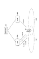
The configuration of the wireless communication system according to the third embodiment will be described below with reference to the drawings. FIG. 10 is a diagram illustrating a wireless communication system according to the third embodiment.
図10に示すように、無線通信システムは、無線端末10と、複数の基地局100(基地局100a及び基地局100b)と、無線制御装置200を有する。
As illustrated in FIG. 10, the wireless communication system includes a
基地局100aは、セルAを有しており、基地局100bは、セルBを有している。例えば、基地局100aに設けられたセルAは、無線端末10がサービングセルとして用いるセルである。一方で、基地局100bに設けられたセルBは、無線端末10が非サービングセルとして用いるセルである。
The base station 100a has a cell A, and the base station 100b has a cell B. For example, the cell A provided in the base station 100a is a cell that the
このように、サービングセル及び非サービングセルが異なる基地局に設けられていても、第1実施形態又は第2実施形態で説明したRGの送信間隔の制御が適用可能である。 As described above, even when the serving cell and the non-serving cell are provided in different base stations, the control of the RG transmission interval described in the first embodiment or the second embodiment is applicable.
[その他の実施形態]
本発明は上述した実施形態によって説明したが、この開示の一部をなす論述及び図面は、この発明を限定するものであると理解すべきではない。この開示から当業者には様々な代替実施形態、実施例及び運用技術が明らかとなろう。
[Other Embodiments]
Although the present invention has been described with reference to the above-described embodiments, it should not be understood that the descriptions and drawings constituting a part of this disclosure limit the present invention. From this disclosure, various alternative embodiments, examples and operational techniques will be apparent to those skilled in the art.
例えば、ガードカウンタは、経過時間をカウントアップするように構成されるが、これに限定されるものではない。具体的には、ガードカウンタは、所定非送信時間(ガード閾値)から経過時間をカウントダウンするように構成されていてもよい。 For example, the guard counter is configured to count up the elapsed time, but is not limited thereto. Specifically, the guard counter may be configured to count down the elapsed time from a predetermined non-transmission time (guard threshold).
同様に、トリガカウンタは、継続時間をカウントアップするように構成されるが、これに限定されるものではない。具体的には、トリガカウンタは、所定保留時間(トリガ閾値)から継続時間をカウントダウンするように構成されていてもよい。 Similarly, the trigger counter is configured to count up the duration, but is not limited thereto. Specifically, the trigger counter may be configured to count down the duration from a predetermined holding time (trigger threshold).
無線端末10、基地局100、通信部110、セルA機能部120、スケジューリング部120a、AG制御部121、RG制御部122、再送制御部123、送信スロット割当部124、セルB機能部130、干渉測定部131、カウンタ132、RG制御部133、記憶部134、セルC機能部140、セルD機能部150、無線制御装置200
Claims (7)
前記非サービングセルは、前記上り方向ユーザデータの伝送速度の減少を指示する前記相対伝送速度制御データを送信する間隔である送信間隔を制御する制御部を有し、
前記非サービングセルは、自セルにおける受信電力が所定条件を満たした状態の継続時間を計時するトリガカウンタを有しており、
前記制御部は、トリガカウンタによって計時される継続時間が所定保留時間となるまで、前記上り方向ユーザデータの伝送速度の減少を指示する前記相対伝送速度制御データの送信を保留し、
前記所定条件は、他セルを前記サービングセルとして用いる無線端末から受信するデータの受信電力が所定干渉電力以上であるという条件であることを特徴とする無線通信システム。 A serving cell for transmitting absolute transmission rate control data for directly specifying the transmission rate of uplink user data and relative transmission rate control data for relatively specifying the transmission rate of the uplink user data to a wireless terminal; A wireless communication system including a non-serving cell that transmits the relative transmission rate control data to a wireless terminal without transmitting the absolute transmission rate control data,
The non-serving cell, have a control unit for controlling the transmission interval is an interval for transmitting the relative transmission rate control data for instructing a decrease of the transmission rate of the uplink user data,
The non-serving cell has a trigger counter that counts the duration of the state in which the received power in the own cell satisfies a predetermined condition,
The control unit suspends transmission of the relative transmission rate control data instructing a decrease in the transmission rate of the uplink user data until the duration timed by the trigger counter reaches a predetermined suspension time,
The wireless communication system , wherein the predetermined condition is a condition that received power of data received from a wireless terminal using another cell as the serving cell is equal to or higher than a predetermined interference power .
前記制御部は、前記ガードカウンタによって計時される前記経過時間が所定非送信時間となるまで、前記上り方向ユーザデータの伝送速度の減少を指示する前記相対伝送速度制御データの送信を規制することを特徴とする請求項1に記載の無線通信システム。 The non-serving cell has a guard counter that counts an elapsed time that is an elapsed time since the transmission of the relative transmission rate control data instructing a decrease in the transmission rate of the uplink user data;
The control unit regulates transmission of the relative transmission rate control data instructing a decrease in the transmission rate of the uplink user data until the elapsed time counted by the guard counter reaches a predetermined non-transmission time. The wireless communication system according to claim 1.
前記非サービングセルが、前記上り方向ユーザデータの伝送速度の減少を指示する前記相対伝送速度制御データの送信間隔を制御するステップを含み、
前記非サービングセルは、自セルにおける受信電力が所定条件を満たした状態の継続時間を計時するトリガカウンタを有しており、
前記制御するステップでは、トリガカウンタによって計時される継続時間が所定保留時間となるまで、前記上り方向ユーザデータの伝送速度の減少を指示する前記相対伝送速度制御データの送信を保留し、
前記所定条件は、他セルを前記サービングセルとして用いる無線端末から受信するデータの受信電力が所定干渉電力以上であるという条件であることを特徴とする無線通信方法。 The serving cell transmits to the wireless terminal absolute transmission rate control data for directly specifying the uplink user data transmission rate and relative transmission rate control data for relatively specifying the uplink user data transmission rate. A wireless communication method in which the non-serving cell transmits the relative transmission rate control data to the wireless terminal without transmitting the absolute transmission rate control data,
The non-serving cell, see contains the step of controlling the transmission interval of the relative transmission rate control data for instructing a decrease of the transmission rate of the uplink user data,
The non-serving cell has a trigger counter that counts the duration of the state in which the received power in the own cell satisfies a predetermined condition,
In the controlling step, the transmission of the relative transmission rate control data instructing a decrease in the transmission rate of the uplink user data is suspended until the duration timed by the trigger counter reaches a predetermined suspension time,
The wireless communication method according to claim 1, wherein the predetermined condition is a condition that reception power of data received from a wireless terminal using another cell as the serving cell is equal to or greater than a predetermined interference power .
前記非サービングセルは、前記上り方向ユーザデータの伝送速度の減少を指示する前記相対伝送速度制御データの送信間隔を制御する制御部を有し、
前記非サービングセルは、自セルにおける受信電力が所定条件を満たした状態の継続時間を計時するトリガカウンタを有しており、
前記制御部は、トリガカウンタによって計時される継続時間が所定保留時間となるまで、前記上り方向ユーザデータの伝送速度の減少を指示する前記相対伝送速度制御データの送信を保留し、
前記所定条件は、他セルを前記サービングセルとして用いる無線端末から受信するデータの受信電力が所定干渉電力以上であるという条件であることを特徴とする基地局。 A serving cell for transmitting absolute transmission rate control data for directly specifying the transmission rate of uplink user data and relative transmission rate control data for relatively specifying the transmission rate of the uplink user data to a wireless terminal; In a wireless communication system including a non-serving cell that transmits the relative transmission rate control data to the wireless terminal without transmitting the absolute transmission rate control data, a base station having the non-serving cell,
The non-serving cell, have a control unit for controlling the transmission interval of the relative transmission rate control data for instructing a decrease of the transmission rate of the uplink user data,
The non-serving cell has a trigger counter that counts the duration of the state in which the received power in the own cell satisfies a predetermined condition,
The control unit suspends transmission of the relative transmission rate control data instructing a decrease in the transmission rate of the uplink user data until the duration timed by the trigger counter reaches a predetermined suspension time,
The base station is characterized in that the received power of data received from a wireless terminal using another cell as the serving cell is a condition that the received power is equal to or higher than a predetermined interference power .
Priority Applications (5)
| Application Number | Priority Date | Filing Date | Title |
|---|---|---|---|
| JP2007263534A JP5090843B2 (en) | 2007-10-09 | 2007-10-09 | Wireless communication system, wireless communication method, and base station |
| US12/246,576 US20090092120A1 (en) | 2007-10-09 | 2008-10-07 | Radio communication system, radio communication method and base station |
| EP08017668A EP2048911A1 (en) | 2007-10-09 | 2008-10-08 | Radio communication system, radio communication method and base station for controlling the transmission interval of a relative grant |
| KR1020080098597A KR101010231B1 (en) | 2007-10-09 | 2008-10-08 | Radio communication system, radio communication method, and base station |
| CNA2008101699249A CN101409925A (en) | 2007-10-09 | 2008-10-09 | Radio communication system, radio communication method and base station |
Applications Claiming Priority (1)
| Application Number | Priority Date | Filing Date | Title |
|---|---|---|---|
| JP2007263534A JP5090843B2 (en) | 2007-10-09 | 2007-10-09 | Wireless communication system, wireless communication method, and base station |
Publications (2)
| Publication Number | Publication Date |
|---|---|
| JP2009094804A JP2009094804A (en) | 2009-04-30 |
| JP5090843B2 true JP5090843B2 (en) | 2012-12-05 |
Family
ID=40386176
Family Applications (1)
| Application Number | Title | Priority Date | Filing Date |
|---|---|---|---|
| JP2007263534A Expired - Fee Related JP5090843B2 (en) | 2007-10-09 | 2007-10-09 | Wireless communication system, wireless communication method, and base station |
Country Status (5)
| Country | Link |
|---|---|
| US (1) | US20090092120A1 (en) |
| EP (1) | EP2048911A1 (en) |
| JP (1) | JP5090843B2 (en) |
| KR (1) | KR101010231B1 (en) |
| CN (1) | CN101409925A (en) |
Families Citing this family (17)
| Publication number | Priority date | Publication date | Assignee | Title |
|---|---|---|---|---|
| CN102045764B (en) * | 2009-10-20 | 2014-02-19 | 华为技术有限公司 | Method and device for adaptive retransmission of high speed uplink packet access |
| US8780943B2 (en) | 2011-10-17 | 2014-07-15 | Golba Llc | Method and system for utilizing multiplexing to increase throughput in a network of distributed transceivers with array processing |
| CN103249092A (en) * | 2012-02-02 | 2013-08-14 | 华为技术有限公司 | Method and terminal for sending data |
| US9226092B2 (en) | 2012-08-08 | 2015-12-29 | Golba Llc | Method and system for a distributed configurable transceiver architecture and implementation |
| CN105900377B (en) * | 2014-09-02 | 2019-10-18 | 华为技术有限公司 | A kind of method and apparatus transmitting data |
| US10854995B2 (en) | 2016-09-02 | 2020-12-01 | Movandi Corporation | Wireless transceiver having receive antennas and transmit antennas with orthogonal polarizations in a phased array antenna panel |
| US10199717B2 (en) | 2016-11-18 | 2019-02-05 | Movandi Corporation | Phased array antenna panel having reduced passive loss of received signals |
| US10321332B2 (en) | 2017-05-30 | 2019-06-11 | Movandi Corporation | Non-line-of-sight (NLOS) coverage for millimeter wave communication |
| US10916861B2 (en) | 2017-05-30 | 2021-02-09 | Movandi Corporation | Three-dimensional antenna array module |
| US10484078B2 (en) | 2017-07-11 | 2019-11-19 | Movandi Corporation | Reconfigurable and modular active repeater device |
| US10348371B2 (en) | 2017-12-07 | 2019-07-09 | Movandi Corporation | Optimized multi-beam antenna array network with an extended radio frequency range |
| US10090887B1 (en) | 2017-12-08 | 2018-10-02 | Movandi Corporation | Controlled power transmission in radio frequency (RF) device network |
| US10862559B2 (en) | 2017-12-08 | 2020-12-08 | Movandi Corporation | Signal cancellation in radio frequency (RF) device network |
| US10637159B2 (en) | 2018-02-26 | 2020-04-28 | Movandi Corporation | Waveguide antenna element-based beam forming phased array antenna system for millimeter wave communication |
| US11088457B2 (en) | 2018-02-26 | 2021-08-10 | Silicon Valley Bank | Waveguide antenna element based beam forming phased array antenna system for millimeter wave communication |
| US11145986B2 (en) | 2018-12-26 | 2021-10-12 | Silicon Valley Bank | Lens-enhanced communication device |
| US11205855B2 (en) | 2018-12-26 | 2021-12-21 | Silicon Valley Bank | Lens-enhanced communication device |
Family Cites Families (10)
| Publication number | Priority date | Publication date | Assignee | Title |
|---|---|---|---|---|
| JP3678967B2 (en) * | 2000-02-23 | 2005-08-03 | 日本電信電話株式会社 | Transmission control circuit in digital radio communication system |
| US7193966B2 (en) * | 2001-06-25 | 2007-03-20 | Telefonakitebolaget Lm Ericsson (Publ) | Triggered packet data rate change in a communication system |
| US8139523B2 (en) * | 2004-11-10 | 2012-03-20 | Ntt Docomo. Inc. | Mobile communication system, mobile station, and radio base station |
| KR100663278B1 (en) * | 2004-11-15 | 2007-01-02 | 삼성전자주식회사 | Method and apparatus for the transmission and reception of downlink control information in mobile telecommunication system supporting uplink packet data service |
| CN100425087C (en) * | 2005-02-07 | 2008-10-08 | 上海贝尔阿尔卡特股份有限公司 | Base-station scheduling method and system for HSUPA |
| CN100576955C (en) * | 2005-02-07 | 2009-12-30 | 上海贝尔阿尔卡特股份有限公司 | A kind of terminal operation method and device thereof based on the non-serving base stations relative order |
| EP1885147B1 (en) * | 2005-04-28 | 2011-03-30 | NTT DoCoMo, Inc. | Transmission rate control method and radio base station |
| EP1811800A1 (en) * | 2006-01-23 | 2007-07-25 | Alcatel Lucent | Method, base station, and communication network supporting high-speed uplink packet access (HSUPA) with soft handover mechanisms |
| US7660279B2 (en) * | 2006-01-27 | 2010-02-09 | Alcatel-Lucent Usa Inc. | Method of scheduling uplink resource in a wireless communication system |
| JP4620620B2 (en) | 2006-03-30 | 2011-01-26 | 三井造船株式会社 | Waste gasifier and operating method thereof |
-
2007
- 2007-10-09 JP JP2007263534A patent/JP5090843B2/en not_active Expired - Fee Related
-
2008
- 2008-10-07 US US12/246,576 patent/US20090092120A1/en not_active Abandoned
- 2008-10-08 KR KR1020080098597A patent/KR101010231B1/en not_active IP Right Cessation
- 2008-10-08 EP EP08017668A patent/EP2048911A1/en not_active Withdrawn
- 2008-10-09 CN CNA2008101699249A patent/CN101409925A/en active Pending
Also Published As
| Publication number | Publication date |
|---|---|
| KR101010231B1 (en) | 2011-01-21 |
| CN101409925A (en) | 2009-04-15 |
| JP2009094804A (en) | 2009-04-30 |
| US20090092120A1 (en) | 2009-04-09 |
| EP2048911A1 (en) | 2009-04-15 |
| KR20090036518A (en) | 2009-04-14 |
Similar Documents
| Publication | Publication Date | Title |
|---|---|---|
| JP5090843B2 (en) | Wireless communication system, wireless communication method, and base station | |
| JP5108450B2 (en) | Wireless communication system, wireless communication method, base station, and wireless terminal | |
| JP5039593B2 (en) | Wireless communication system, wireless communication method, and base station | |
| JP5055431B2 (en) | Base station, radio communication system and radio communication method | |
| JP5171196B2 (en) | Wireless communication system, wireless communication method, and base station | |
| JP5164512B2 (en) | Wireless communication system, wireless communication method, and base station | |
| JP4989513B2 (en) | Wireless communication system, wireless communication method, and base station | |
| JP5117837B2 (en) | Wireless communication system, wireless communication method, and base station | |
| JP5135119B2 (en) | Base station, host station and radio communication system | |
| JP5184141B2 (en) | Wireless communication system, wireless communication method, and base station | |
| JP5118071B2 (en) | Base station, radio communication system and radio communication method | |
| JP5030730B2 (en) | Wireless communication system, wireless communication method, and base station |
Legal Events
| Date | Code | Title | Description |
|---|---|---|---|
| A621 | Written request for application examination |
Free format text: JAPANESE INTERMEDIATE CODE: A621 Effective date: 20100922 |
|
| A977 | Report on retrieval |
Free format text: JAPANESE INTERMEDIATE CODE: A971007 Effective date: 20120613 |
|
| A131 | Notification of reasons for refusal |
Free format text: JAPANESE INTERMEDIATE CODE: A131 Effective date: 20120619 |
|
| A521 | Request for written amendment filed |
Free format text: JAPANESE INTERMEDIATE CODE: A523 Effective date: 20120817 |
|
| TRDD | Decision of grant or rejection written | ||
| A01 | Written decision to grant a patent or to grant a registration (utility model) |
Free format text: JAPANESE INTERMEDIATE CODE: A01 Effective date: 20120904 |
|
| A01 | Written decision to grant a patent or to grant a registration (utility model) |
Free format text: JAPANESE INTERMEDIATE CODE: A01 |
|
| A61 | First payment of annual fees (during grant procedure) |
Free format text: JAPANESE INTERMEDIATE CODE: A61 Effective date: 20120913 |
|
| FPAY | Renewal fee payment (event date is renewal date of database) |
Free format text: PAYMENT UNTIL: 20150921 Year of fee payment: 3 |
|
| R150 | Certificate of patent or registration of utility model |
Ref document number: 5090843 Country of ref document: JP Free format text: JAPANESE INTERMEDIATE CODE: R150 Free format text: JAPANESE INTERMEDIATE CODE: R150 |
|
| R250 | Receipt of annual fees |
Free format text: JAPANESE INTERMEDIATE CODE: R250 |
|
| R250 | Receipt of annual fees |
Free format text: JAPANESE INTERMEDIATE CODE: R250 |
|
| R250 | Receipt of annual fees |
Free format text: JAPANESE INTERMEDIATE CODE: R250 |
|
| R250 | Receipt of annual fees |
Free format text: JAPANESE INTERMEDIATE CODE: R250 |
|
| R250 | Receipt of annual fees |
Free format text: JAPANESE INTERMEDIATE CODE: R250 |
|
| R250 | Receipt of annual fees |
Free format text: JAPANESE INTERMEDIATE CODE: R250 |
|
| LAPS | Cancellation because of no payment of annual fees |