JP5089214B2 - Image processing method and apparatus, computer program, and storage medium - Google Patents
Image processing method and apparatus, computer program, and storage medium Download PDFInfo
- Publication number
- JP5089214B2 JP5089214B2 JP2007082740A JP2007082740A JP5089214B2 JP 5089214 B2 JP5089214 B2 JP 5089214B2 JP 2007082740 A JP2007082740 A JP 2007082740A JP 2007082740 A JP2007082740 A JP 2007082740A JP 5089214 B2 JP5089214 B2 JP 5089214B2
- Authority
- JP
- Japan
- Prior art keywords
- pixel
- image
- resolution
- flag
- value
- Prior art date
- Legal status (The legal status is an assumption and is not a legal conclusion. Google has not performed a legal analysis and makes no representation as to the accuracy of the status listed.)
- Expired - Fee Related
Links
- 238000003672 processing method Methods 0.000 title claims description 25
- 238000004590 computer program Methods 0.000 title description 2
- 238000006243 chemical reaction Methods 0.000 claims description 164
- 238000000034 method Methods 0.000 claims description 163
- 230000008569 process Effects 0.000 claims description 149
- 238000001914 filtration Methods 0.000 claims description 37
- 239000011159 matrix material Substances 0.000 description 24
- 238000010586 diagram Methods 0.000 description 12
- 238000004364 calculation method Methods 0.000 description 10
- 238000009877 rendering Methods 0.000 description 10
- 230000006870 function Effects 0.000 description 9
- 230000006835 compression Effects 0.000 description 7
- 238000007906 compression Methods 0.000 description 7
- 230000006837 decompression Effects 0.000 description 7
- 238000012935 Averaging Methods 0.000 description 5
- 230000000694 effects Effects 0.000 description 5
- 230000015654 memory Effects 0.000 description 5
- 230000005540 biological transmission Effects 0.000 description 2
- 230000015572 biosynthetic process Effects 0.000 description 2
- 230000003111 delayed effect Effects 0.000 description 2
- 238000005516 engineering process Methods 0.000 description 2
- 230000009467 reduction Effects 0.000 description 2
- 238000009825 accumulation Methods 0.000 description 1
- 230000008859 change Effects 0.000 description 1
- 239000003086 colorant Substances 0.000 description 1
- 238000006073 displacement reaction Methods 0.000 description 1
- 230000003287 optical effect Effects 0.000 description 1
- 230000002093 peripheral effect Effects 0.000 description 1
- 239000011295 pitch Substances 0.000 description 1
- 230000002250 progressing effect Effects 0.000 description 1
- 230000017105 transposition Effects 0.000 description 1
Images


Classifications
-
- G—PHYSICS
- G06—COMPUTING; CALCULATING OR COUNTING
- G06T—IMAGE DATA PROCESSING OR GENERATION, IN GENERAL
- G06T3/00—Geometric image transformations in the plane of the image
- G06T3/40—Scaling of whole images or parts thereof, e.g. expanding or contracting
- G06T3/4023—Scaling of whole images or parts thereof, e.g. expanding or contracting based on decimating pixels or lines of pixels; based on inserting pixels or lines of pixels
-
- H—ELECTRICITY
- H04—ELECTRIC COMMUNICATION TECHNIQUE
- H04N—PICTORIAL COMMUNICATION, e.g. TELEVISION
- H04N1/00—Scanning, transmission or reproduction of documents or the like, e.g. facsimile transmission; Details thereof
- H04N1/40—Picture signal circuits
- H04N1/40068—Modification of image resolution, i.e. determining the values of picture elements at new relative positions
-
- H—ELECTRICITY
- H04—ELECTRIC COMMUNICATION TECHNIQUE
- H04N—PICTORIAL COMMUNICATION, e.g. TELEVISION
- H04N1/00—Scanning, transmission or reproduction of documents or the like, e.g. facsimile transmission; Details thereof
- H04N1/40—Picture signal circuits
- H04N1/409—Edge or detail enhancement; Noise or error suppression
- H04N1/4092—Edge or detail enhancement
Landscapes
- Engineering & Computer Science (AREA)
- Multimedia (AREA)
- Signal Processing (AREA)
- Physics & Mathematics (AREA)
- General Physics & Mathematics (AREA)
- Theoretical Computer Science (AREA)
- Image Processing (AREA)
- Record Information Processing For Printing (AREA)
- Color, Gradation (AREA)
- Editing Of Facsimile Originals (AREA)
- Facsimile Image Signal Circuits (AREA)
Description
本発明は画像処理方法及びその装置、コンピュータプログラム及び記憶媒体に関する。特に、擬似高解像度変換処理によって低解像度に解像度変換された画像データと生成された属性データとに基づいて、精度よく変換前の画像データを復元する解像度変換処理に関するものである。 The present invention relates to an image processing method and apparatus, a computer program, and a storage medium. In particular, the present invention relates to resolution conversion processing for accurately restoring image data before conversion based on image data that has been converted to low resolution by pseudo high-resolution conversion processing and generated attribute data.
近年のプリンタにおける高画質化はめざましく、エンジンの高解像度化やそれに伴う処理部の高速化、メモリ容量の増大が急速に進んでいる。しかし、それら全てを満たすためには膨大なコストがかかってしまうため、現在では高画質や高速化と、低コスト化との両立を図るためにいくつかの方法が提案されている。 In recent years, the image quality in printers is remarkable, and the resolution of the engine, the speed of the processing unit, and the increase in memory capacity are rapidly progressing. However, since enormous costs are required to satisfy all of these requirements, several methods have been proposed to achieve both high image quality, high speed, and low cost.
例えば、従来から電子写真方式のプリンタで行われている方法としては、エンジンの解像度をそのままにして、低い解像度の画像データを用いて各画素のドットピッチ間で重なるように感光体上に露光する方法がある。これによって、画素間の重なる部分も有効画素となるように潜像を形成させる。これは、実解像度よりも擬似的に高い解像度で画像を再現するスポット多重化と呼ばれている(例えば、特許文献1参照)。 For example, as a method conventionally used in an electrophotographic printer, the image is exposed on the photoconductor so as to overlap between the dot pitches of the respective pixels using the low resolution image data while keeping the resolution of the engine as it is. There is a way. As a result, a latent image is formed so that the overlapping portion between the pixels also becomes an effective pixel. This is called spot multiplexing in which an image is reproduced at a pseudo-higher resolution than the actual resolution (see, for example, Patent Document 1).
ところが、上記スポット多重化による方法では、通常のプロセスに比べ不安定で制御が難しいことや、文字や線画において背景とオブジェクトとの境界が不鮮明になる、文字がつぶれてしまう、ジャギーが発生するといったことが起こる。この問題を解決するため、例えば、受信したベクトルデータの画像をエンジン解像度よりも低い解像度のラスターデータの画像に展開して、最終的にエンジン解像度になるようにラスターデータの画像を解像度変換して出力する。これにより、コントローラ内部では低解像度を維持し、出力時に擬似的に高い解像度で画像を再現する方法が提案されている(例えば、特許文献2参照)。
上記特許文献1の原理を用いたプリンタにおいて、プリンタ内部の画像処理部でフィルタ処理を行って高解像度の画像を低解像度の画像に変換し、その低解像度の画像からスポット多重化を利用して擬似的に高解像度を再現するものである。
In a printer using the principle of
このように、前述のスポット多重化を利用した従来技術(例えば特許文献1)やその上記改良技術では、低い解像度の画像を擬似的に高い解像度の画像として再現できるため画像記憶領域のメモリ容量を削減できるなどのメリットがある。しかしながら、1つのドットを再現するために隣り合った2つの露光部分の重なり部分から潜像を形成するため画像が不安定になることがあり、小フォントや細線の再現が苦手でコントロールが難しいという問題点が残る。 As described above, the conventional technology using the above-described spot multiplexing (for example, Patent Document 1) and the improved technology can reproduce a low-resolution image as a high-resolution image in a pseudo manner. There are advantages such as reduction. However, in order to reproduce one dot, a latent image is formed from the overlapping part of two adjacent exposure parts, so the image may become unstable, and it is difficult to control small fonts and fine lines and difficult to control. The problem remains.
また、前述の従来技術(例えば特許文献2)では、ベクトルデータをエンジン解像度よりも低い解像度のラスターデータの画像へとレンダリングして記憶した後、出力時にエンジン解像度へと解像度変換を行う。このため、コントローラ内のメモリ領域を削減しながら、スポット多重化といった制御の難しい方法を用いずに安定して高解像度の画像再現を実現している。しかしながら、レンダリングされるラスターデータが低解像度であるため、高解像度のラスターデータに直接展開した場合と比べて再現性が十分でないといった問題点がある。したがって、高解像度画像の復元というには十分でない解像度変換技術であった。 In the above-described prior art (for example, Patent Document 2), vector data is rendered and stored as an image of raster data having a resolution lower than the engine resolution, and then the resolution is converted to the engine resolution at the time of output. For this reason, while reducing the memory area in the controller, stable and high-resolution image reproduction is realized without using a difficult control method such as spot multiplexing. However, since the raster data to be rendered has a low resolution, there is a problem in that the reproducibility is not sufficient as compared with the case where the raster data is directly developed into high resolution raster data. Therefore, this is a resolution conversion technique that is not sufficient for restoring a high-resolution image.
本発明は、前記従来技術の問題点に鑑み、擬似高解像度変換のフィルタ処理によって生成されたハーフドットを出力解像度に再変換すると同時に元の画像に近い画像へと復元できる画像処理方法及びその装置を提供する。 In view of the above-described problems of the prior art, the present invention is an image processing method and apparatus capable of reconverting half dots generated by the filter processing of pseudo high resolution conversion into output resolution and at the same time restoring an image close to the original image. I will provide a.
そのため、ハーフドットのまま画像を再現するよりも安定し、エッジ部分などに現れるジャギーなどの発生を防ぐことができる画像処理方法及びその装置を提供する。 Therefore, the present invention provides an image processing method and apparatus that are more stable than reproducing an image with half dots and can prevent the occurrence of jaggies or the like appearing at an edge portion.
更に、多値の属性データに基づいて多値の入力画像のパターンを判定し、柔軟に出力パターンを指定できる画像処理方法及びその装置を提供する。 Furthermore, the present invention provides an image processing method and apparatus capable of determining a pattern of a multi-value input image based on multi-value attribute data and flexibly specifying an output pattern.
そのため、従来の解像度変換に比べ擬似高解像度変換された画像をより高精度に復元することが可能であり、小フォントや細線にも対応することができる画像処理方法及びその装置を提供する。 Therefore, it is possible to provide an image processing method and apparatus that can restore an image that has been subjected to pseudo-high resolution conversion with higher accuracy than conventional resolution conversion, and that can deal with small fonts and fine lines.
上述した課題を解決するために、本発明の画像処理方法は、第1解像度の多値画像を前記第1解像度より低い第2解像度の多値画像に変換した後に、前記第2解像度の多値画像から前記第1解像度の多値画像を復元する画像処理方法であって、前記第1解像度の多値画像から前記第2解像度の多値画像への変換では、該変換前の画素の属性フラグに対応する変換を行い、当該対応した変換を施したことを示す変換処理フラグを該変換後の画素データに対応付けて保持する保持工程と、前記第2解像度の多値画像から前記第1解像度の多値画像への復元では、前記第2解像度の多値画像の注目画素と該注目画素の周囲の画素に対応付けて保持された前記変換処理フラグを用いて、該注目画素の画素データを複数画素からなる画素データに置き換える置換工程と、を有し、前記属性フラグに対応する変換がフィルタ処理の場合には、前記変換処理フラグは、フィルタ処理による解像度変換を施したことを示すフィルタ処理フラグと、該フィルタ処理を施した後の画素値が該フィルタ処理以前の画素値よりも小さくなったことを示すハーフドットフラグとを含み、前記第2解像度の多値画像から前記第1解像度の多値画像への復元において、前記置換工程は、前記注目画素と該注目画素の周囲の画素の前記フィルタ処理フラグと前記ハーフドットフラグとを用いて、予め定められたパターンとのパターンマッチングを行い、該注目画素の画素データを複数画素からなる画素データに置き換える、ことを特徴とする。
In order to solve the above-described problem, the image processing method according to the present invention converts a multi-value image of a first resolution into a multi-value image of a second resolution lower than the first resolution, and then multi-value of the second resolution. An image processing method for restoring the first resolution multi-value image from the image, wherein in the conversion from the first resolution multi-value image to the second resolution multi-value image, the attribute flag of the pixel before the conversion A conversion process flag indicating that the corresponding conversion has been performed, and holding the conversion processing flag in association with the pixel data after the conversion, and the first resolution from the multi-value image of the second resolution In the multi-valued image, the pixel data of the target pixel is converted using the conversion processing flag held in association with the target pixel of the multi-value image of the second resolution and the surrounding pixels of the target pixel. Replace with pixel data consisting of multiple pixels Includes a displacement step that, a, wherein when the attribute flag corresponding to the conversion of the filter processing, the conversion processing flag and filtering flag indicating that subjected to resolution conversion by filtering, the filter processing A half-dot flag indicating that the pixel value after application has become smaller than the pixel value before the filter processing, and in the restoration from the multi-value image of the second resolution to the multi-value image of the first resolution The replacement step performs pattern matching with a predetermined pattern using the filter processing flag and the half-dot flag of the pixel of interest and pixels around the pixel of interest, and pixel data of the pixel of interest Is replaced with pixel data composed of a plurality of pixels .
また、本発明の画像処理方法は、第2解像度の画像から前記第2解像度よりも高い第1解像度の画像を生成する画像処理方法であって、フィルタ処理による解像度変換を施したことを示すフィルタ処理フラグと、該フィルタ処理を施した後の画素値が該フィルタ処理以前の画素値よりも小さくなったことを示すハーフドットフラグとが付加された前記第2解像度の画像データを入力する入力工程と、該入力された前記第2解像度の画像データ中の注目画素と該注目画素の周囲の画素とに付加された前記フィルタ処理フラグと前記ハーフドットフラグとを用いて、予め定められたパターンとのパターンマッチングを行い、前記注目画素の画素データを複数画素からなる画素データに置き換えることで前記第1解像度の画像を生成する生成工程と、を有することを特徴とする。The image processing method of the present invention is an image processing method for generating an image having a first resolution higher than the second resolution from an image having a second resolution, wherein the filter indicates that resolution conversion has been performed by filter processing. An input step of inputting the image data of the second resolution to which a processing flag and a half dot flag indicating that the pixel value after the filtering process is smaller than the pixel value before the filtering process are added A predetermined pattern using the filter processing flag and the half-dot flag added to the target pixel in the input image data of the second resolution and the pixels around the target pixel, and Generating a first resolution image by performing pattern matching and replacing pixel data of the target pixel with pixel data composed of a plurality of pixels; Characterized in that it has a.
擬似高解像度変換のフィルタ処理によって生成されたハーフドットを、出力解像度に再変換すると同時に元の画像に近い画像へと復元できる。そのため、ハーフドットのまま画像を再現するよりも安定し、また、エッジ部分などに現れるジャギーなどの発生を防ぐことができる。 Half dots generated by the pseudo high resolution conversion filter processing can be reconverted to output resolution and simultaneously restored to an image close to the original image. Therefore, it is more stable than reproducing an image with half dots, and it is possible to prevent the occurrence of jaggies or the like appearing at the edge portion.
更に、多値の属性データに基づいて多値の入力画像のパターンを判定し、柔軟に出力パターンを指定できる。そのため、従来の解像度変換に比べ擬似高解像度変換された画像をより高精度に復元することが可能であり、小フォントや細線にも対応することができる。 Furthermore, it is possible to determine the pattern of the multi-value input image based on the multi-value attribute data and to specify the output pattern flexibly. Therefore, it is possible to restore an image that has been subjected to pseudo high resolution conversion with higher accuracy than conventional resolution conversion, and it is possible to deal with small fonts and fine lines.
以下、図面に基づいて本発明の実施形態を詳細に説明する。なお、以下の実施形態では、本発明を適用する画像処理装置として印刷装置を例に説明するが、本発明は比較的に高解像度の多値画像の蓄積や処理の簡略化と、元の高解像度画像への良好な再現性とを実現する画像処理に係る発明であり、印刷装置に限定されない。例えば、適用する装置は、表示装置であってもよいし、画像蓄積装置であってもよいし、画像送信装置であってもよい。 Hereinafter, embodiments of the present invention will be described in detail with reference to the drawings. In the following embodiments, a printing apparatus will be described as an example of an image processing apparatus to which the present invention is applied. However, the present invention is simplified in the accumulation and processing of a relatively high resolution multi-valued image, The invention relates to image processing that realizes good reproducibility to a resolution image, and is not limited to a printing apparatus. For example, the device to be applied may be a display device, an image storage device, or an image transmission device.
<本実施形態の画像処理装置の構成例>
図1Aは、本発明の画像処理装置の一実施形態である印刷装置(以下プリンタ)の制御構成を説明するブロック図である。
<Example of Configuration of Image Processing Device of Present Embodiment>
FIG. 1A is a block diagram illustrating a control configuration of a printing apparatus (hereinafter referred to as a printer) which is an embodiment of an image processing apparatus of the present invention.
図1Aにおいて、101はホストコンピュータであり、色情報、文字、図形、イメージ画像、コピー枚数等の印刷処理を行う印刷情報をプリンタ102へ送出する。
In FIG. 1A,
プリンタ102は、次の構成を含む。プリンタ102は、画像処理部103と、画像処理部103から送出された画像信号の基づいて実際の画像形成を行うプリンタエンジン104とに大別される。プリンタエンジン104は、本例では解像度1200dpiのエンジン解像度を持つ。
The
以下、画像処理部103における主な構成及びその動作について説明する。
Hereinafter, main configurations and operations of the
画像処理部103において、105はホストコンピュータ101との印刷情報の送受信を制御するインターフェイスである。オブジェクト生成部106は、ホストコンピュータ101から入力された印刷情報である色、文字、図形、イメージ画像等の情報を中間情報(以下オブジェクト)に変換してRAM115に格納する。
In the
次に、オブジェクト生成部106で変換・格納されたオブジェクトに基づいて、レンダリング部107で、描画対象となるビットイメージを例えばビット数8bit、解像度1200dpiとなるよう生成してRAM115に格納する。このとき、オブジェクトに付加されている印刷情報に基づいて、レンダリングされた画像の1画素毎に対応したオブジェクト情報をフラグ(以下、属性フラグ)として与えた多値のデータ(以下、属性データ)を生成する。レンダリング部107で生成される属性フラグには、カラー/モノクロフラグ、フォントフラグ、グラフィックフラグ、イメージフラグ、細線フラグがある。
Next, based on the object converted and stored by the
更に、擬似高解像度変換処理部108において、属性データに基づきレンダリングされた解像度1200dpiの画像に後述する擬似高解像度変換処理を行って、解像度600dpiの画像を生成する。そして、後述する各種属性フラグを属性データとして設定する。
Further, the pseudo high resolution
次に、圧縮/伸長部109において、レンダリング部107で生成し、擬似高解像度変換処理部108で擬似高解像度変換された解像度600dpiのビットイメージと属性データとを圧縮して、ハードディスク110へとスプール、格納しておく。
Next, the compression /
次処理の要求にしたがって、ハードディスク110より格納しておいたビットイメージと属性データとを読み出し、伸長を行って画像処理部103へ送出する。
In accordance with the next processing request, the bit image and attribute data stored in the
高解像度変換処理部111では、圧縮/伸長部109で伸長された解像度600dpiのビットイメージに、同様に伸長された属性データの属性フラグに基づいて後述する高解像度変換処理を行って、解像度1200dpiのビットイメージに復元する。高解像度変換処理部111では、ラインバッファ設けることによって、後述する高解像度変換処理のためのウィンドウを形成する。本実施形態では、4ライン分のビットマップデータを遅延させて(5×5)画素で構成されるウィンドウを形成し、かかるウィンドウ内のウィンドウパターンに基づく処理により高解像度変換処理が行われる。
The high resolution
このようにして解像度1200dpiに復元されたビットイメージは、中間調処理部112において中間調処理が行われて出力階調に落ちた後、プリンタエンジン104に送出されて記憶媒体上に画像が形成される。
The bit image restored to the resolution of 1200 dpi is subjected to halftone processing in the
また、114は中央演算処理装置(CPU)で、ROM113に格納されたプログラムにしたがって、上記各処理部での各種処理の判断や制御を行う。113はROM(リードオンリーメモリ)である。ROM113には、図5,図6,図16,図24のフローチャートに示すプログラムを含む各種制御プログラム113aと、後述する擬似高解像度変換テーブル113bと、マッチングパターン113cと、画素置き換えパターン113dとが格納されている。115はRAM(ランダムアクセスメモリ)であり、CPU114がROM113に格納されたプログラムに従って各処理の判断制御を行うためのデータやステータス情報を格納し、更に、作業領域1150として使用される。
(ROM113及びRAM115の記憶構成例)
図1Bは、本実施形態に係るROM113及びRAM115の記憶構成例を示した図である。なお、図1Bには、本実施形態の関連の深いプログラム及びデータのみを図示しており、一般的なあるいは関連の薄いものは図示されていない。
(Storage configuration example of
FIG. 1B is a diagram illustrating a storage configuration example of the
まず、ROM113の記憶構成例を説明する。図1Bの参照番号は、図1Aの参照番号に対応している。
First, a storage configuration example of the
制御プログラム113aには、本実施形態では以下のようなプログラムやモジュールが含まれる。まず、図1Aの各処理部を実現するオブジェクト生成プログラム113a-1が記憶されている。また、レンダリング・プログラム113a-2が記憶されている。また、擬似高解像度変換プログラム113a-2が記憶されている。また、圧縮/伸張プログラム113a-4が記憶されている。また、高解像度変換プログラム113a-5が記憶されている。また、中間調処理プログラム113a-8が記憶されている。本実施形態の特徴である高解像度変換プログラム113a-5には、後述の背景/最大画素値検索モジュール113a-6や3値化処理モジュール113a-7などが含まれている。更に、図1Aの画像処理部103の外部装置とのインタフェースを制御するインタフェース・プログラム113a-9も格納されている。例えば、ホストコンピュータ101とのインタフェースを制御するホスト・インタフェース、プリンタエンジン104とのインタフェースを制御するプリンタ・インタフェース、ハードディスク110とのインタフェースを制御するディスク・インタフェースを含む。更に、図示しないが、表示操作部を介してユーザとのインタフェースを制御するユーザ・インタフェースも含まれる。
In the present embodiment, the
そして、本実施形態で使用される各テーブルとして、擬似高解像度変換テーブル113bと、マッチングパターン113cと、画素置き換えパターン113dとが格納されている。
A pseudo high resolution conversion table 113b, a
次に作業領域としてのRAM115には、本実施形態で使用される以下のデータを記憶する領域が確保される。
Next, an area for storing the following data used in the present embodiment is secured in the
ホストコンピュータ101からの入力からプリンタエンジン104への出力までの画像データとして、以下のようなデータが記憶される。ホストコンピュータ101からの画像データである入力印刷情報115a、オブジェクト生成部106で生成されたオブジェクト形式の中間情報115b、レンダリング部107でレンダリングされた属性フラグ付きのビットイメージ115cが記憶される。また、擬似高解像度変換処理部108で低解像度に変換された属性フラグを含む属性データ付きの擬似高解像度変換データ115d、圧縮/伸張部109で圧縮されてハードディスク110に格納される圧縮データ115eが記憶される。また、ハードディスク110から読み出されて圧縮/伸張部109で伸張された伸張データ115f(このデータは、擬似高解像度変換データ115dに略等しい)が記憶される。また、本実施形態の高解像度変換処理部111で高解像度に再現された高解像度変換データ115g、中間調処理部112で中間調処理されてプリンタエンジン104に出力されるプリンタ出力データ115hが記憶される。
The following data is stored as image data from the input from the
また、各処理に使用されるパラメータとして、本実施形態の擬似高解像度変換処理部108でのフィルタ処理で使用される、2×2フィルタ係数115i、3×3フィルタ係数115jが記憶される。また、実施形態2で使用される画素値の閾値TH1〜TH4(115k)が記憶される。
Further, 2 × 2
本実施形態の処理の途中で一時記憶される中間データとしては、以下のデータが記憶される。擬似高解像度変換処理部108の処理における、最大画素値115m、注目画素の属性データ(属性フラグを含む)115n、注目画素の低解像度変換値115pが記憶される。また、高解像度変換処理部111の処理における、最大画素値115q、背景画素値115r、5×5マトリックス115s、マッチング処理結果のマッチング・インデックス115tが記憶される。また、注目画素の属性データ(属性フラグを含む)など115u、注目画素の3値データ115y、注目画素の高解像度置換値115w、実施形態2で使用される注目画素の出力画素数115xが記憶される。
The following data is stored as intermediate data temporarily stored during the processing of this embodiment. In the process of the pseudo high resolution
本実施形態の処理の分岐などで使用されるフラグとしては、解像度の変換処理と処理結果を示す変換処理フラグである、ハーフトーンであることを示すハーフドットフラグ115y、フィルタ処理フラグ115zが、各画素データに対して一時記憶される。これらは、擬似高解像度変換処理部108の処理結果により生成されて、像域を表わす属性データとして保持される。
As flags used in the branch of the processing of the present embodiment, a
<本実施形態の画像処理装置の動作例>
<擬似高解像度変換処理部108の構成及び動作例>
まず、図2〜図4を参照して、本実施形態の画像形成装置102の画像処理部103内、擬似高解像度変換処理部108の構成及び動作例を説明する。
<Example of Operation of Image Processing Apparatus of Present Embodiment>
<Configuration and Operation Example of Pseudo High Resolution
First, a configuration and an operation example of the pseudo high resolution
図2は、レンダリング部107によってレンダリングされた解像度1200dpiのビットイメージの一部を示す一例を示す図である。図3は、後述するフィルタ処理に用いるフィルタ係数の一例を示す図である。図4は、図2に示すビットイメージを擬似高解像度変換処理部108で行われる擬似高解像変換処理によって変換した結果の一例を示す図である。
FIG. 2 is a diagram illustrating an example of a part of a bit image having a resolution of 1200 dpi rendered by the
レンダリング部107で解像度1200dpiのビットイメージにレンダリングされた入力画像は、擬似高解像度変換処理部108において低解像度に変換される。低解像度への変換処理は、図3に示す擬似高解像度変換テーブル113bによって後述する2×2フィルタ処理、3×3フィルタ処理、または後述する注目画素値の間引き処理や、後述する最大画素値の置き換え処理により行われる。
An input image rendered as a bit image having a resolution of 1200 dpi by the
これらの処理は、例えば、図2の入力画像に示す画素座標(i,j)の両座標ともに奇数を示すときの画素を注目画素として行われる。本例では、注目画素の画素値や、注目画素と周囲の近傍画素に対応する属性フラグに基づいて、適意上述の処理の切り替えを行い、注目画素と近傍画素に対して行われる。以上の処理が注目画素を順次に移しながら1200dpiのビットイメージ全体に対して適用されることで、本例では解像度が半分の600dpiのビットイメージを生成する。 These processes are performed using, for example, a pixel when the pixel coordinates (i, j) shown in the input image of FIG. In this example, based on the pixel value of the target pixel and the attribute flags corresponding to the target pixel and surrounding neighboring pixels, the above-described processing is appropriately switched, and the processing is performed on the target pixel and the neighboring pixels. The above processing is applied to the entire 1200 dpi bit image while sequentially shifting the target pixel, thereby generating a 600 dpi bit image with half the resolution in this example.
(2×2フィルタ処理例)
図3の(a)は2×2フィルタ係数の一例を示す図である。
(Example of 2 × 2 filter processing)
FIG. 3A shows an example of a 2 × 2 filter coefficient.
前述の2×2フィルタ処理は、例えば図2の入力画像に対しては、入力画像の両座標ともに奇数である画素座標(iodd,jodd)が注目画素となるとき、次式によって算出され解像度600dpiのビットイメージ1画素を生成する。 The 2 × 2 filter processing described above is calculated by the following equation when the pixel coordinates (iodd, jodd) in which both coordinates of the input image are odd numbers are the target pixel, for example, for the input image of FIG. One pixel of the bit image is generated.

Din(i,j)は、解像度1200dpiの入力画像の画素座標(i、j)の画素値を、Doutは、2×2フィルタ処理によって生成される入力画像の座標(i,j)に対応した画素座標の解像度600dpiの出力画像の画素値を示す。F2x2(x,y)は、図3の(a)に示す2×2フィルタの座標(x,y)が持つ重み付け係数の値を示す。 Din (i, j) corresponds to the pixel value of the pixel coordinate (i, j) of the input image having a resolution of 1200 dpi, and Dout corresponds to the coordinate (i, j) of the input image generated by the 2 × 2 filter processing. A pixel value of an output image having a pixel coordinate resolution of 600 dpi is shown. F2x2 (x, y) indicates the value of the weighting coefficient possessed by the coordinates (x, y) of the 2 × 2 filter shown in FIG.
(3×3フィルタ処理例)
図3の(b)は、3×3フィルタ係数の一例を示す図である。
(Example of 3 × 3 filter processing)
FIG. 3B is a diagram illustrating an example of a 3 × 3 filter coefficient.
前述の3×3フィルタ処理は、前述の2×2フィルタ処理と同様にして行われる。例えば図2の入力画像に対しては、入力画像の両座標ともに奇数である画素座標(iodd,jodd)が注目画素となるとき、次式によって算出され解像度600dpiのビットイメージ1画素を生成する。 The 3 × 3 filter process described above is performed in the same manner as the 2 × 2 filter process described above. For example, for the input image of FIG. 2, when pixel coordinates (iodd, jodd), which are odd numbers in both coordinates of the input image, become the target pixel, one pixel of a bit image having a resolution of 600 dpi calculated by the following equation is generated.
Din(i,j)は、解像度1200dpiの入力画像の画素座標(i、j)の画素値を、Doutは、3×3フィルタ処理によって生成される入力画像の座標(i,j)に対応した画素座標の解像度600dpiの出力画像の画素値を示す。F3x3(x,y)は、図3の(b)に示す3×3フィルタの座標(x,y)が持つ重み付け係数の値を示す。 Din (i, j) corresponds to the pixel value (i, j) of the input image having a resolution of 1200 dpi, and Dout corresponds to the coordinate (i, j) of the input image generated by the 3 × 3 filter processing. A pixel value of an output image having a pixel coordinate resolution of 600 dpi is shown. F3x3 (x, y) indicates the value of the weighting factor possessed by the coordinates (x, y) of the 3 × 3 filter shown in (b) of FIG.
(間引き処理例)
前述の注目画素値の間引き処理は、本例では次のように行われる。例えば図2の入力画像に対しては、入力画像の両座標ともに奇数である画素座標(iodd,jodd)が注目画素となるとき、その画素値であるDin(iodd,jodd)、出力画像Doutとしてビットイメージ1画素を生成する。すなわち、1画素間隔で画素値を間引くことに相当するため、解像度600dpiの1画素を生成することと同義となる。
(Thinning processing example)
In the present example, the above-described thinning process of the target pixel value is performed as follows. For example, in the case of the input image of FIG. 2, when pixel coordinates (iodd, jodd) that are odd numbers in both coordinates of the input image become the target pixel, the pixel value Din (iodd, jodd) and output image Dout One pixel of the bit image is generated. In other words, this corresponds to thinning out pixel values at intervals of one pixel, which is equivalent to generating one pixel with a resolution of 600 dpi.
(置き換え処理例)
前述の最大画素値の置き換え処理は、本例では次のように行われる。例えば図2の入力画像に対しては、入力画像の両座標ともに奇数である画素座標(iodd,jodd)が注目画素となるとき、以下の画素内から最大画素値を検出し、最大画素値を解像度600dpiビットイメージ1画素のDoutとして生成する。例えば、画素値Din(iodd−1,jodd−1),Din(iodd,jodd−1),Din(iodd−1,jodd),Din(iodd,jodd)の4画素内から最大画素値を検出する。もしくは、次の9画素内から最大画素値を検出する。9画素は、左側の3画素Din(iodd−1,jodd−1),Din(iodd,jodd−1),Din(iodd+1,jodd−1)を含む。また、中央の3画素Din(iodd−1,jodd),Din(iodd,jodd),Din(iodd+1,jodd)を含む。また、右側のDin(iodd−1,jodd+1),Din(iodd,jodd+1),Din(iodd+1,jodd+1)を含む。
(Example of replacement processing)
The replacement process of the maximum pixel value described above is performed as follows in this example. For example, in the case of the input image of FIG. 2, when pixel coordinates (iodd, jodd) in which both coordinates of the input image are odd numbers become the target pixel, the maximum pixel value is detected from the following pixels, and the maximum pixel value is determined. A resolution of 600 dpi bit image is generated as Dout of one pixel. For example, the maximum pixel value is detected from four pixels of pixel values Din (iodd−1, jodd−1), Din (iodd−1, jodd−1), Din (iodd−1, jodd), and Din (iodd, jodd). . Alternatively, the maximum pixel value is detected from the next nine pixels. The nine pixels include the left three pixels Din (iodd-1, jodd-1), Din (iodd, jodd-1), and Din (iodd + 1, jodd-1). Further, it includes three central pixels Din (iodd−1, jodd), Din (iodd, jodd), and Din (iodd + 1, jodd). Also, Din (iodd-1, jod + 1), Din (iodd, jodd + 1), Din (iodd + 1, jodd + 1) on the right side are included.
(解像度変換の切り替え例)
上記処理は入力画像の1画素毎に対応する属性データ中の属性フラグに基づき適意切り替えて処理されるが、その一例を以下に示す。
(Resolution conversion switching example)
The above processing is performed by appropriately switching based on the attribute flag in the attribute data corresponding to each pixel of the input image. An example is shown below.
注目画素もしくは近傍の画素に対応する属性データにおいてイメージフラグがONのとき、もしくはフラグが無い場合、注目画素の間引き処理が選択される。また、グラフィックフラグが共にONの場合、最大画素値の置き換え処理が選択される。上記条件以外の場合は、注目画素データである画素値に応じた重み付け係数のフィルタが選択されて、フィルタ処理が行われる。 When the image flag is ON in the attribute data corresponding to the target pixel or a neighboring pixel, or when there is no flag, the target pixel thinning-out process is selected. When both graphic flags are ON, replacement processing for the maximum pixel value is selected. In cases other than the above conditions, a filter with a weighting coefficient corresponding to the pixel value that is the target pixel data is selected and the filter process is performed.
また、フィルタ処理時には、2×2フィルタ処理、3×3フィルタ処理に関わらず注目画素に対応する属性データにフィルタ処理フラグを付加する。更に、フィルタ処理によって生成・出力された画素の画素値が注目画素データであるフィルタ処理以前の画素値より小さくなった画素については、ハーフドットフラグを付加する。 At the time of filter processing, a filter processing flag is added to attribute data corresponding to the pixel of interest regardless of 2 × 2 filter processing or 3 × 3 filter processing. Further, a half dot flag is added to a pixel whose pixel value generated and output by the filter process is smaller than the pixel value before the filter process as the target pixel data.
(擬似高解像度変換処理の結果例)
図4は、図2の解像度1200dpiのビットイメージの一部を、前述の属性フラグのルールに基づいて擬似高解像度変換処理を行って生成された解像度600dpiのビットイメージの一例を示す図である。図2において、黒で塗られた画素201が画素値aの値を持ち、且つフォントフラグがONであって、白で塗られた画素202が値とフラグを持たない画素であった場合である。
(Example result of pseudo high-resolution conversion processing)
FIG. 4 is a diagram showing an example of a 600 dpi resolution bit image generated by performing a pseudo high resolution conversion process on a part of the 1200 dpi resolution bit image of FIG. 2 based on the attribute flag rule described above. In FIG. 2, the
前述の属性フラグのルールによって、注目画素もしくは近傍画素にフォントフラグがある画素に関してはフィルタ処理が行われる。その結果、図2の黒で塗られた画素201は、図4に示す黒で塗られた画素401、もしくは斜線で示された薄い画素402、中間の画素403、濃い画素404のいずれかに変換される。一方、図2でフラグが無い場合には、注目画素の間引き処理によって白く塗られている画素405に置き換えられる。
According to the rule of the attribute flag described above, a filter process is performed for a pixel having a font flag in the target pixel or a neighboring pixel. As a result, the
図4における黒で塗られた画素401は、図2の黒で示された画素201と同じ画素値aをもっており、変換処理によってフィルタ処理フラグが付加されている。図4における斜線で塗られた薄い画素402は、フィルタ処理によって算出された画素値a/4の値を持ち、且つフォントフラグ、フィルタ処理フラグ、ハーフドットフラグがONの状態となっている。また、図4における斜線で塗られた中間の画素403は、フィルタ処理によって算出された画素値2a/4の値を持ち、且つフォントフラグ、フィルタ処理フラグ、ハーフドットフラグがONの状態である。図4の濃い画素404は、画素値3a/4の値を持ち、且つフォントフラグ、フィルタ処理フラグ、ハーフドットフラグがONの状態となっている。
The
なお、本実施形態では説明を容易にするために、実行されるフィルタ処理において使用されるフィルタ係数は注目画素の画素値に関わらず一定で、図3の(a)に示す2×2フィルタのみとしている。もちろん、注目画素の画素値に合わせて多数のフィルタ係数を切り替えて実施すると、更に効果的となることは容易に想像できよう。 In the present embodiment, for ease of explanation, the filter coefficient used in the filter processing to be executed is constant regardless of the pixel value of the target pixel, and only the 2 × 2 filter shown in FIG. It is said. Of course, it can be easily imagined that it is more effective if a large number of filter coefficients are switched in accordance with the pixel value of the target pixel.
<実施形態1の高解像度変換処理部111の構成及び動作例>
次に、図5のフローチャートを用いて、実施形態1における高解像度変換処理部111で行われる高解像度変換処理の全体の手順例を説明する。
<Configuration and Operation Example of High Resolution
Next, an example of the entire procedure of the high resolution conversion process performed by the high resolution
高解像度変換処理部111には、上述の圧縮/伸長部109で伸長された解像度600dpiのビットイメージと、同様にして伸長された属性データが入力される。4ライン分ラインバッファで遅延させた後、ラインバッファ中のビットイメージから中心座標を注目画素とする(5×5)画素で構成されるウィンドウを生成する(S501)。
The high resolution
中心座標の注目画素に対応する属性データより、注目画素がフィルタ処理によって生成された画素か否かの判定を行う(S502)。 It is determined from the attribute data corresponding to the target pixel of the center coordinate whether or not the target pixel is a pixel generated by the filtering process (S502).
ステップS502によって注目画素がフィルタ処理によって生成されたものであったと判定された場合、後述する背景/最大画素値検索処理によって、ウィンドウ内、もしくはラインバッファ中から背景画素値と画像中の最大画素値とを抽出する(S503)。次に、中心座標の注目画素に対応する属性データより、注目画素がフィルタ処理によってハーフドット化されているか、更に前述の背景/最大画素値検索S503によって背景画素値と最大画素値とを算出できたかを判定する(S504)。 If it is determined in step S502 that the pixel of interest has been generated by the filtering process, the background pixel value and the maximum pixel value in the image are retrieved from the window or line buffer by the background / maximum pixel value search process described later. Are extracted (S503). Next, from the attribute data corresponding to the pixel of interest at the center coordinate, whether the pixel of interest is half-dotted by filtering, or the background pixel value and the maximum pixel value can be calculated by the background / maximum pixel value search S503 described above. (S504).
ステップS504において注目画素がハーフドット化されていて、背景画素値と最大画素値とが算出されたと判定された場合、後述するマッチングパターンのインデックスをチェックして、次処理のマッチングパターンの有無を判定する(S505)。ステップS505によって次処理のマッチングパターンがあると判定された場合、マッチングパターンとそれに対応する画素置き換えパターンをセットする(S506)。 If it is determined in step S504 that the target pixel is half-dotted and the background pixel value and the maximum pixel value are calculated, the matching pattern index described later is checked to determine the presence or absence of the matching pattern for the next process. (S505). If it is determined in step S505 that there is a matching pattern for the next process, a matching pattern and a corresponding pixel replacement pattern are set (S506).
ステップS501で生成されたウィンドウ内の各画素に対して、ウィンドウ内の各画素に対応する属性データに基づいて、後述する3値化処理を行う(S507)。3値化処理(S507)によって3値化されたウィンドウと、ステップS506でセットされたマッチングパターンとで後述するパターンマッチングを行う(S508)。マッチング(S508)で3値化されたウィンドウとセットされたマッチングパターンとが一致したかを判定する(S509)。 Based on the attribute data corresponding to each pixel in the window, a ternary process described later is performed on each pixel in the window generated in step S501 (S507). Pattern matching, which will be described later, is performed using the window binarized by the binarization process (S507) and the matching pattern set in step S506 (S508). It is determined whether the window ternarized by matching (S508) matches the set matching pattern (S509).
判定の結果、一致していた場合には、マッチングパターンに対応付けられた画素置き換えパターンにしたがって後述する画素の置き換え処理を行う(S510)。なお、一致しなかったと判定された場合にはS505に戻る。 As a result of the determination, if they match, pixel replacement processing described later is performed according to the pixel replacement pattern associated with the matching pattern (S510). If it is determined that they do not match, the process returns to S505.
前述の属性判定(S502)によって、注目画素がフィルタ処理によって生成されてない、すなわち、注目画素の間引き処理や最大画素の置き換え処理によって生成されたと判定されると、注目画素の画素値を出力のための4画素に置き換える(S511)。更に、前述のハーフドット判定(S504)によって、注目画素がハーフドット化されていない、もしくは背景画素値と最大画素値とが算出されていないと判定された場合も、同様に、上記S511で同様の画素置き換え処理が行われる。更に、前述のマッチングパターンの判定(S505)によって全てのマッチングパターンが終了したと判定された場合も、同様に、上記S511で同様の画素置き換え処理が行われる。 If it is determined by the attribute determination (S502) that the target pixel has not been generated by the filtering process, that is, it has been generated by the thinning process or the maximum pixel replacement process, the pixel value of the target pixel is output. (S511). Further, when it is determined by the above half dot determination (S504) that the target pixel is not half-dotted or the background pixel value and the maximum pixel value are not calculated, the same applies to S511. The pixel replacement process is performed. Furthermore, when it is determined that all the matching patterns have been completed by the above-described matching pattern determination (S505), the same pixel replacement process is similarly performed in S511.
ステップS510、ステップS511のいずれかによって生成された4画素を、600dpi1画像の注目画素に対する1200dpi画像の4画素として出力する(S512)。最後に、ラインバッファの終端に達したか否かを判定し(S513)、終端の場合は処理を終了して次ラインの処理を待ち、そうでない場合には次画素処理のためにステップS501に戻る。
The four pixels generated by either step S510 or step S511 are output as four pixels of a 1200 dpi image with respect to the target pixel of the 600
(背景/最大画素値検索処理S503の手順例)
次に、図6のフローチャートを用いて、前述の背景/最大画素値検索処理S503の詳細な処理手順例について説明する。
(Example of background / maximum pixel value search processing S503)
Next, a detailed processing procedure example of the background / maximum pixel value search processing S503 will be described with reference to the flowchart of FIG.
まず、図5のステップS501によって生成されたウィンドウ内を順次走査して、各画素に対応付けられた属性データに基づいて背景画素と最大画素とを検索する(S601)。ここで背景画素とは、各画素に対応付けられた属性データにおいてフィルタ処理フラグがOFFであって、注目画素に最近隣の画素を示す。また、最大画素とは、各画素に対応付けられた属性データにおいてフィルタ処理フラグがONでハーフドットフラグがOFFであって、注目画素に最近隣の画素を示す。 First, the inside of the window generated in step S501 of FIG. 5 is sequentially scanned to search for the background pixel and the maximum pixel based on the attribute data associated with each pixel (S601). Here, the background pixel is a pixel nearest to the pixel of interest when the filtering flag is OFF in the attribute data associated with each pixel. The maximum pixel indicates a pixel nearest to the target pixel when the filter processing flag is ON and the half dot flag is OFF in the attribute data associated with each pixel.
次に、背景画素及び最大画素がウィンドウ内から検出されたかを判定する(S602)。背景画素及び最大画素ともに検出されたと判定された場合、それら画素に対応する画素値をそれぞれ背景画素値及び最大画素値として出力する(S603)。 Next, it is determined whether the background pixel and the maximum pixel are detected from the window (S602). If it is determined that both the background pixel and the maximum pixel are detected, the pixel values corresponding to these pixels are output as the background pixel value and the maximum pixel value, respectively (S603).
背景画素あるいは最大画素が検出されていないと判定された場合の処理は、次のようになる。すなわち、ウィンドウが生成されたラインバッファ内において、ウィンドウが生成された画素座標の外から走査方向(本実施形態では右方向となる)の画素に対して後述するルールに従って検索を行う(S604)。 The processing when it is determined that the background pixel or the maximum pixel is not detected is as follows. That is, in the line buffer in which the window is generated, a search is performed according to a rule to be described later with respect to pixels in the scanning direction (in the present embodiment, the right direction) from outside the pixel coordinates where the window is generated (S604).
背景画素及び最大画素がウィンドウ内、もしくはラインバッファ内から検出されたかを判定 (S605)し、検出されればステップS603においてそれぞれに対応する画素値を背景画素値及び最大画素値として出力する。背景画素あるいは最大画素が検出されていないと判定された場合、ウィンドウ内において後述する最大画素値の算出を行う(S606)。 It is determined whether the background pixel and the maximum pixel are detected in the window or the line buffer (S605). If detected, the corresponding pixel values are output as the background pixel value and the maximum pixel value in step S603. When it is determined that the background pixel or the maximum pixel is not detected, the maximum pixel value described later is calculated in the window (S606).
最大画素値がウィンドウ内で算出でき、且つ背景画素を検出できたかを判定 (S607)し、両者が算出または検出できている場合はステップS603においてそれぞれに対応する画素値を背景画素値及び最大画素値として出力する。 It is determined whether the maximum pixel value can be calculated in the window and the background pixel can be detected (S607). If both can be calculated or detected, the corresponding pixel value is determined as the background pixel value and the maximum pixel in step S603. Output as a value.
(背景/最大画素値検索処理の具体例)
図7は、図2から擬似高解像度変換処理により生成された図4中で、画素座標(9,2)を注目画素としたときのウィンドウである。図7を例にとって、前述の背景/最大画素値検索処理の動作の具体例を詳細に説明する。図7は、前述した画素401、画素403、画素404、画素405でウィンドウを構成している。
(Specific example of background / maximum pixel value search processing)
FIG. 7 is a window when the pixel coordinate (9, 2) is the target pixel in FIG. 4 generated by the pseudo high resolution conversion process from FIG. Using FIG. 7 as an example, a specific example of the operation of the background / maximum pixel value search process will be described in detail. In FIG. 7, the above-described
図6のS601では、背景画素は、属性データのフィルタ処理フラグがOFFであって注目画素に最近隣の画素であり、画素座標(2,1)の画素405となる。一方、最大画素は、属性データのフィルタ処理フラグがONでハーフドットフラグがOFFであって注目画素に最近隣の画素であり、画素座標(3,2)の画素401と検出される。したがって、図6のS603において、背景画素値0、最大画素値aが出力される。
In S601 of FIG. 6, the background pixel is the pixel nearest to the pixel of interest with the attribute data filtering flag OFF, and is the
図8は、図2から擬似高解像度変換処理により生成された図4中で、画素座標(2,2)を注目画素としたときのウィンドウである。図4と図8を例にとって、前述の背景/最大画素値検索処理のステップS604においてラインバッファ内を検索する動作を詳細に説明する。図8は、前述した画素402、画素403、画素405でウィンドウを構成している。
FIG. 8 is a window when the pixel coordinate (2, 2) is the target pixel in FIG. 4 generated by the pseudo high resolution conversion process from FIG. Taking FIG. 4 and FIG. 8 as an example, the operation of searching the line buffer in step S604 of the background / maximum pixel value search process described above will be described in detail. In FIG. 8, the above-described
図6のS601において、背景画素は、属性データのフィルタ処理フラグがOFFであって注目画素に最近隣の画素であり、画素座標(2,1)の画素405となる。一方、最大画素は、属性データのフィルタ処理フラグがONでハーフドットフラグがOFFであって注目画素に最近隣の画素であり、ウィンドウ内において検出することができない。よって、図6のS604のラインバッファ内の検索が行われる。
In S601 of FIG. 6, the background pixel is the pixel nearest to the pixel of interest with the attribute data filtering flag OFF, and is the
ラインバッファ内では、ウィンドウが形成された画素座標より外から走査方向に検索を行う。つまり、図4の画素座標(5,0)、(5,1)、(5,2)、(5,3)、(5,4)より右の画素座標に位置する画素が対象となる。検索は、それぞれ5つのラインメモリにおいて同じ位置となる5画素すべてが全フラグOFF、もしくはラインの終端となるまで検索を続けるというルールで実行される。図8においては、最大画素が図4中の画素座標(10,2)にて検出されることから、図6のS603で背景画素値0、最大画素値aが出力される。
In the line buffer, a search is performed in the scanning direction from outside the pixel coordinates where the window is formed. That is, the pixel located at the pixel coordinates on the right side of the pixel coordinates (5, 0), (5, 1), (5, 2), (5, 3), and (5, 4) in FIG. The search is executed according to a rule that the search is continued until all the five pixels at the same position in each of the five line memories are all flag OFF or the end of the line. In FIG. 8, since the maximum pixel is detected at the pixel coordinates (10, 2) in FIG. 4, the
図9は、図2から擬似高解像度変換処理により生成された図4中で、画素座標(16,2)を注目画素としたときのウィンドウである。図4と図9を例にとって、前述の背景/最大画素値検索処理のステップS606において最大画素値を算出する動作を詳細に説明する。図9は、前述した画素403、画素405でウィンドウを構成している。
FIG. 9 is a window when the pixel coordinate (16, 2) is the target pixel in FIG. 4 generated by the pseudo high resolution conversion process from FIG. Taking FIG. 4 and FIG. 9 as an example, the operation for calculating the maximum pixel value in step S606 of the background / maximum pixel value search process will be described in detail. In FIG. 9, the above-described
図6のS601において、背景画素は、属性データのフィルタ処理フラグがOFFであって注目画素に最近隣の画素であるため、画素座標(3,2)の画素405となる。一方、最大画素は、属性データのフィルタ処理フラグがONでハーフドットフラグがOFFであって注目画素に最近隣の画素であり、ウィンドウ内において検出することができない。よって、図6のS604のラインバッファ内の検索が行われる。検索対象となる範囲は、図4の画素座標(19,0)、(19,1)、(19,2)、(19,3)、(19,4)より右の画素座標に位置する画素であるが、5画素すべてが全フラグOFFであるため図6のS604でも最大画素が検出されない。よって、図6のS606において最大画素値の算出が行われる。
In S601 of FIG. 6, the background pixel is the
最大画素値の算出は、擬似高解像度変換処理部108で実行されるフィルタ処理のフィルタとフィルタ係数が限られた後述する条件の時に実行される。上述の条件とは、2×2フィルタ処理のみで、画素値に応じてフィルタ係数を変化させない擬似高解像度変換処理されたビットイメージの場合である。この場合に、擬似高解像度変換処理部108の設定が保存されているレジストリやROM113の擬似高解像度変換テーブル113bを参照することで、本処理の切り替えを行うことができる。
The calculation of the maximum pixel value is executed under the conditions described later in which the filters and filter coefficients of the filter processing executed by the pseudo high resolution
図9においては、図3の(a)に示すフィルタ係数で2×2フィルタ処理されたビットイメージであり、条件と一致するため最大画素値の算出が実行される。算出方法は以下のとおりである。ウィンドウ内の第1の画素列において同じ画素値が2画素連続して存在し、且つ第1の画素列に隣接する第2の画素列において上記2画素と同じ行位置に2画素連続して以下の比となる画素値が存在するとき、それら4画素の画素値の和の1/2を最大画素値とする。 FIG. 9 shows a bit image that has been subjected to 2 × 2 filter processing with the filter coefficient shown in FIG. 3A, and the maximum pixel value is calculated because it matches the condition. The calculation method is as follows. In the first pixel column in the window, the same pixel value continuously exists in two pixels, and in the second pixel column adjacent to the first pixel column, two pixels continuously in the same row position as the above two pixels When there is a pixel value that is the ratio of the two, the maximum pixel value is ½ of the sum of the pixel values of the four pixels.
第1の画素列の画素値:第2の画素列の画素値
=(F2x2(0, 0)+F2x2(1, 0)):(F2x2(0, 1)+F2x2(1, 1))
すなわち、図9においては上記比が(1:1)であって、画素座標(1,0)と(2,0)が画素値a/2を持つため、これら画素を含む画素列が上記第1の画素列となる。また、画素座標(1,1)と(2,1)が画素値a/2を持つため上記第2の画素列となる。これら第1の画素列の2画素の画素値と第2の画素列の2画素の画素値とが上記比の関係と一致するため、これら4画素の画素値の和2aの1/2である画素値aが、図9におけるウィンドウの最大画素値として算出される。そして、図6のS603において背景領域の背景画素値0、最大画素値aが出力される。
Pixel value of the first pixel column: Pixel value of the second pixel column = (F2x2 (0, 0) + F2x2 (1, 0)): (F2x2 (0, 1) + F2x2 (1, 1))
That is, in FIG. 9, since the ratio is (1: 1) and the pixel coordinates (1, 0) and (2, 0) have the pixel value a / 2, the pixel column including these pixels is 1 pixel column. Further, since the pixel coordinates (1, 1) and (2, 1) have the pixel value a / 2, the second pixel column is obtained. Since the pixel values of the two pixels in the first pixel column and the pixel values of the two pixels in the second pixel column agree with the above relationship, it is ½ of the sum 2a of the pixel values of these four pixels. The pixel value a is calculated as the maximum pixel value of the window in FIG. Then, in S603 of FIG. 6, the
(マッチングパターンの例)
図10、図11、図12、図13、図14、図15を用いて、前述のパターンマッチングで使用するマッチングパターンについて説明する。図10、図11、図12、図13、図14はそれぞれ、本実施形態におけるマッチングパターン1001、1101、1201、1301、1401と画素置き換えパターン1002、1102、1202、1302、1402の一例を示す図である。マッチングパターンにはそれぞれインデックスが付けられており、図15のテーブルによって画素置き換えパターンと対応付けて準備され管理される。
(Example of matching pattern)
A matching pattern used in the above-described pattern matching will be described with reference to FIGS. 10, 11, 12, 13, 14, and 15. FIGS. 10, 11, 12, 13, and 14 are diagrams showing examples of the
マッチングパターン1001、1101、1201、1301、1401は、5×5のマトリックスで与えられ、マトリックス内のそれぞれの数字は以下の7値の数字に対応している。
0:無視
1:背景画素
2:ハーフドット画素
3:最大画素
4:背景画素以外
5:ハーフドット画素以外
6:最大画素以外
画素置き換えパターン1002、1102、1202、1302、1402は、2×2のマトリックスで与えられ、マトリックス内のそれぞれの数字は以下の2値の数字に対応している。
0:背景画素値
1:最大画素値
(3値化処理S507の手順例)
図16のフローチャートを用いて3値化処理の手順例について説明する。
The
0: Ignored 1: Background pixel 2: Half dot pixel 3: Maximum pixel 4: Other than background pixel 5: Other than half dot pixel 6: Other than maximum pixel The
0: Background pixel value 1: Maximum pixel value (Procedure example of ternary processing S507)
An example of the ternary processing procedure will be described with reference to the flowchart of FIG.
ウィンドウ内の画素座標(x,y)の画素値と属性データとをセットする(S1601)。次に、セットされた属性データを参照し、フィルタ処理フラグがあるかを判定する(S1602)。 The pixel value of pixel coordinates (x, y) and attribute data in the window are set (S1601). Next, with reference to the set attribute data, it is determined whether there is a filter processing flag (S1602).
フィルタ処理フラグがONだった場合は、更に属性データを参照して、ハーフドットフラグがあるかを判定する(S1603)。ハーフドットフラグがONだった場合は、画素座標(x,y)の画素を"2:ハーフドット画素"として出力する(S1604)。ハーフドットフラグがOFFだった場合は、画素座標(x,y)の画素を"3:最大画素"として出力する(S1605)。 If the filter processing flag is ON, it is further determined by referring to the attribute data whether there is a half dot flag (S1603). If the half dot flag is ON, the pixel at pixel coordinates (x, y) is output as “2: half dot pixel” (S1604). If the half dot flag is OFF, the pixel coordinate (x, y) is output as “3: maximum pixel” (S1605).
一方、フィルタ処理フラグがOFFだった場合は、画素座標(x,y)の画素を"1:背景画素"として出力する(S1606)。ウィンドウ内の全画素について上記処理を行う(S1607)。 On the other hand, if the filter processing flag is OFF, the pixel at the pixel coordinate (x, y) is output as “1: background pixel” (S1606). The above processing is performed for all the pixels in the window (S1607).
(3値化処理の具体例)
以下、図7〜図9のウィンドウを3値化処理によって3値化した具体例を説明する。
(Specific example of ternary processing)
Hereinafter, a specific example in which the windows of FIGS. 7 to 9 are ternarized by ternary processing will be described.
図17は、図7のウィンドウを3値化処理によって3値化したものである。また、図18は図8のウィンドウを3値化処理によって3値化したものである。また、図19は図9のウィンドウを3値化処理によって3値化したものである。上記3値化処理のフローを図7、図8、図9についてそれぞれ実施したとき、結果として図17、図18、図19のように処理される。 FIG. 17 is a ternarization of the window of FIG. 7 by ternary processing. FIG. 18 shows a ternarization of the window of FIG. 8 by a ternarization process. FIG. 19 shows a ternarization of the window of FIG. 9 by a ternarization process. When the above-described ternary processing flow is performed for FIGS. 7, 8, and 9, the processing is performed as shown in FIGS. 17, 18, and 19, as a result.
すなわち、図7における黒の画素401は3に、中間の画素403は2に、濃い画素404は2に、白い画素405は1に変換されて、図17のようになる。図8及び図9においても同様に、それぞれ変換されて図18及び図19となる。
That is, the
(マッチング処理S508の具体例)
図17、図18、図19、図20を用いて、前述のマッチングについて説明する。
(Specific example of matching processing S508)
The above-described matching will be described with reference to FIGS. 17, 18, 19, and 20.
図20は、図10に示したマッチングパターンとそれに対応付けられた画素置き換えパターンの一例と、それらを回転(図20の左側)、あるいは転置(図20の右側)させたマトリックスである。すなわち、マッチングパターン2001はマッチングパターン1001を右方向に90度回転させたもの、画素置き換えパターン2002は画素置き換えパターン1002を同様に回転させたものである。以下、2003,2004は1001,1002を180度回転、2005,2006は270度回転させたものである。また、マッチングパターン2007はマッチングパターン1001を転置させたもの、画素置き換えパターン2008は画素置き換えパターン1002を転置させたものである。以下、2009,2010は2001,2002を転置させたもの、2011,2012は2003,2004を転置させたもの、2013,2014は2005,2006を転置させたものである。
FIG. 20 shows an example of the matching pattern shown in FIG. 10 and a pixel replacement pattern associated therewith, and a matrix obtained by rotating (left side of FIG. 20) or transposing (right side of FIG. 20). That is, the
マッチングは、注目画素の周辺画素の画素データに対応して設定された複数の画素の出力順位に従って、1つのマッチングパターンについてマトリックスの回転と転置とを行ってマッチングを行う。マトリックスの回転と転置は画素置き換えパターンについても同様に行う。そして、マッチングによってマッチングパターンのマトリックスの値にある条件と3値化処理されたウィンドウの値とが一致したとき、一致したマッチングパターンに対応付けられた画素置き換えパターンによって、後述する画素の置き換えを行う。かかる処理が、出力画素数置換の処理に相当する。 Matching is performed by rotating and transposing the matrix for one matching pattern in accordance with the output order of a plurality of pixels set corresponding to the pixel data of the peripheral pixels of the target pixel. The matrix rotation and transposition are performed in the same manner for the pixel replacement pattern. Then, when the condition in the matrix value of the matching pattern matches the value of the three-valued window by matching, pixel replacement described later is performed with the pixel replacement pattern associated with the matched matching pattern. . Such processing corresponds to output pixel number replacement processing.
すなわち、図17のウィンドウに対しては、マッチングによってマッチングパターン2011と一致するため、画素置き換えパターン2012が後述する画素の置き換えに利用される。また、図18のウィンドウでは、図11のマッチングパターン1101と一致するため画素置き換えパターン1102が後述する画素の置き換えに使用される。また、図19のウィンドウでは、図14のマッチングパターン1401が180度回転したとき一致するため、画素置き換えパターン1402が180度回転した状態で後述する画素の置き換えに使用される。
That is, since the window of FIG. 17 matches the
(画素置き換え処理S510の具体例)
次に、前述の画素置き換え処理について図21、図22、図23を用いて説明する。
(Specific example of pixel replacement processing S510)
Next, the above-described pixel replacement process will be described with reference to FIGS.
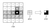
図21の矢印左側は、3値化された図17のウィンドウ1701と、マッチングでウィンドウ1701と一致した図20のマッチングパターンに対応付けられている画素置き換えパターン2012とを示す。図21の矢印右側は、画素置き換え処理によって生成された1200dpiの4画素のビットマップデータ2101である。ウィンドウ1701は、背景/最大画素値検索処理において背景画素値0、最大画素値aであるため、画素置き換えパターン2012のマトリックスに配置された値に従ってマトリックス状に画素を配置して、ビットマップデータ2101を生成する。
The left side of the arrow in FIG. 21 shows the
図22の矢印左側は、3値化された図18のウィンドウ1801と、マッチングでウィンドウ1801と一致した図11のマッチングパターンに対応付けられている画素置き換えパターン1102とを示す。図22の矢印右側は、画素置き換え処理によって生成された1200dpiの4画素のビットマップデータ2201である。ウィンドウ1801は、背景/最大画素値検索処理において背景画素値0、最大画素値aであるため、画素置き換えパターン1102のマトリックスに配置された値に従ってマトリックス状に画素を配置して、ビットマップデータ2201を生成する。
The left side of the arrow in FIG. 22 shows a
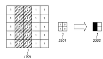
図23の矢印左側は、3値化された図19ウィンドウ1901と、マッチングでウィンドウ1901と図14のマッチングパターン1401が180度回転した状態で一致したため同様に180度回転した画素置き換えパターン2301とを示す。図23の矢印右側は、画素置き換え処理によって生成された1200dpiの4画素のビットマップデータ2302である。ウィンドウ1901は、背景/最大画素値検索処理において背景画素値0、最大画素値aであるため、画素置き換えパターン2301のマトリックスに配置された値に従ってマトリックス状に画素を配置して、ビットマップデータ2302を生成する。
The left side of the arrow in FIG. 23 shows a ternary FIG. 19
(実施形態1の効果)
以上説明してきたように、本実施形態によれば、レンダリング部107において1200dpiにレンダリングされたビットイメージを、擬似高解像度変換部108において600dpiのビットイメージに変換する。この600dpiの1画素のビットイメージに対して、従来のスポット多重化によらず高解像度変換処理部111で図5に示すフローチャートの高解像度変換処理を行って、1200dpiの4画素のビットイメージを生成する。この高解像度変換処理によって、擬似高解像度変換処理された画素に対して変換前に近い状態へと復元することができる。また、複数のマッチングパターンを用いて変換を行うことで、従来は行えなかったより小さいフォントや細線に対しても柔軟に処理を行い復元することができるようになる。また、擬似高解像度変換によって潜像形成などのプロセスが不安定になるスポット多重化技術を用いずに、安定して高い解像度の画像を再現することができる。
(Effect of Embodiment 1)
As described above, according to the present embodiment, the bit image rendered at 1200 dpi in the
<実施形態2の高解像度変換処理部111の構成及び動作例>
以下、図面に基づいて本実施形態の高解像度変換処理部111の構成及び動作例を詳細に説明する。
<Configuration and Operation Example of High Resolution
Hereinafter, a configuration and an operation example of the high resolution
本実施形態における装置の基本的な構成は、上述の実施形態1の説明に用いた図1と同様なため、詳細な説明は省略する。また、擬似高解像度変換処理部108で行われる擬似高解像変換処理についても実施形態1と同様であるので、詳細な説明は省略する。
Since the basic configuration of the apparatus in the present embodiment is the same as that of FIG. 1 used in the description of the first embodiment, detailed description thereof is omitted. The pseudo high resolution conversion process performed by the pseudo high resolution
図24のフローチャートを用いて、本実施形態における高解像度変換処理部111で行われる高解像度変換処理の処理手順例を説明する。
A processing procedure example of the high resolution conversion process performed by the high resolution
ハードディスク110から読み出され上述の圧縮/伸長部109で伸長された解像度600dpiのビットイメージと、同様にして伸長された属性データが、高解像度変換処理部111に入力される。4ライン分ラインバッファに遅延させた後、ラインバッファ中のビットイメージから中心座標を注目画素とする(5×5)画素で構成されるウィンドウを生成する(S2401)。
A 600 dpi resolution bit image read from the
中心座標の注目画素に対応する属性データより、注目画素がフィルタ処理によって生成された画素かの判定を行う(S2402)。ステップS2402によって注目画素がフィルタ処理によって生成されたものであったと判定された場合、背景/最大画素値検索処理によって、ウィンドウ内もしくはラインバッファ中から背景画素値と最大画素値を検索する(S2403)。なお、背景/最大画素値検索処理は上述の実施形態1の処理と同様であるため、ここでの詳細な説明は省略する。 It is determined from the attribute data corresponding to the target pixel in the center coordinates whether the target pixel is a pixel generated by the filtering process (S2402). If it is determined in step S2402 that the pixel of interest has been generated by the filtering process, the background / maximum pixel value search process searches for the background pixel value and the maximum pixel value from within the window or line buffer (S2403). . Note that the background / maximum pixel value search processing is the same as the processing in the first embodiment described above, and thus detailed description thereof is omitted here.
中心座標の注目画素に対応する属性データより、注目画素がフィルタ処理によってハーフドット化されているか、更に前述の背景/最大画素値検索S2403によって背景画素値と最大画素値を算出できたかを判定する(S2404)。 It is determined from the attribute data corresponding to the pixel of interest at the center coordinates whether the pixel of interest has been half-dotted by filtering, and whether the background pixel value and the maximum pixel value have been calculated by the background / maximum pixel value search S2403 described above. (S2404).
ステップS2404において注目画素がハーフドット化されていて、背景画素値と最大画素値とが算出されたと判定された場合、後述する出力画素数の算出(S2405)を行う。 If it is determined in step S2404 that the pixel of interest has been half-dotted and the background pixel value and the maximum pixel value have been calculated, the number of output pixels to be described later is calculated (S2405).
後述するマッチングパターンのインデックスをチェックして次処理のマッチングパターンの有無を判定する(S2406)。ステップS2406によって次処理のマッチングパターンがあると判定された場合、マッチングパターンとそれに対応する画素置き換えパターンをセットする(S2407)。ステップS2401で生成されたウィンドウ内の各画素に対して、ウィンドウ内の各画素に対応する属性データに基づいて3値化処理を行う(S2408)。なお、3値化処理は上述の実施形態1の処理と同様であるため、ここでの詳細な説明は省略する。 A matching pattern index, which will be described later, is checked to determine whether there is a matching pattern for the next process (S2406). If it is determined in step S2406 that there is a matching pattern for the next process, a matching pattern and a corresponding pixel replacement pattern are set (S2407). A ternarization process is performed on each pixel in the window generated in step S2401 based on attribute data corresponding to each pixel in the window (S2408). Since the ternarization process is the same as the process of the first embodiment, a detailed description thereof is omitted here.
3値化処理(S2408)によって3値化されたウィンドウと、ステップS2407でセットされたマッチングパターンとでマッチングを行う(S2409)。なお、マッチングは上述の実施形態1の処理と同様であるため、ここでの詳細な説明は省略する。 Matching is performed between the window that is binarized by the binarization process (S2408) and the matching pattern set in step S2407 (S2409). Note that the matching is the same as the processing of the first embodiment, and thus detailed description thereof is omitted here.
マッチング(S2409)で3値化されたウィンドウとセットされたマッチングパターンとが一致したかの判定(S2410)を行う。一致したと判定された場合、マッチングパターンに対応付けられた画素置き換えパターンにしたがって、後述する画素の置き換え処理を行う(S2411)。なお、S2410によって一致しなかったと判定された場合にはS2406に移る。 It is determined (S2410) whether the window ternarized by matching (S2409) matches the set matching pattern. If it is determined that they match, a pixel replacement process (to be described later) is performed according to the pixel replacement pattern associated with the matching pattern (S2411). If it is determined by S2410 that they do not match, the process moves to S2406.
前述のマッチングパターンの判定(S2406)によって全てのマッチングパターンが終了したと判定された場合には、後述する出力画素の順位付け(S2412)を行って画素置き換えパターンを生成する。そして、求めた画素置き換えパターンに基づいて画素の置き換え処理を行う(S2411)。 If it is determined that all the matching patterns have been completed by the above-described matching pattern determination (S2406), output pixel ranking (S2412) described later is performed to generate a pixel replacement pattern. Then, pixel replacement processing is performed based on the obtained pixel replacement pattern (S2411).
一方、前述の属性判定(S2402)で、注目画素がフィルタ処理から生成されてない、すなわち、注目画素の間引き処理もしくは最大画素の置き換え処理によって生成されと判定された場合は、次の処理をする。すなわち、注目画素の画素値を出力のための4画素に置き換える(S2413)。更に、前述のハーフドット判定(S2404)によって注目画素がハーフドット化されていない、もしくは背景画素値と最大画素値とが算出されていないと判定された場合も、同様に、上記ステップS2413で画素置き換え処理が行われる。 On the other hand, if it is determined in the attribute determination (S2402) that the target pixel has not been generated from the filter process, that is, it has been generated by the target pixel thinning process or the maximum pixel replacement process, the following process is performed. . That is, the pixel value of the target pixel is replaced with four pixels for output (S2413). Further, when it is determined by the above half dot determination (S2404) that the pixel of interest is not half-dotted or the background pixel value and the maximum pixel value are not calculated, the pixel is similarly determined in step S2413. Replacement processing is performed.
ステップS2411、ステップS2413のいずれかによって生成された4画素を、600dpi1画像の注目画素に対応する1200dpi画像の4画素として出力する(S2414)。ラインバッファの終端に達した場合は処理を終了して次ラインの処理を待ち、そうでない場合には次画素処理のためにステップS2401に戻るためのライン終端の判定を行う(S2415)。
The four pixels generated in either step S2411 or step S2413 are output as four pixels of a 1200 dpi image corresponding to the target pixel of the 600
(出力画素数算出S2405の例)
次に、前述の出力画素数の算出S2405について、詳細に説明する。
(Example of output pixel count calculation S2405)
Next, the above-described calculation S2405 of the number of output pixels will be described in detail.
図24のステップS2403によって検索された最大画素値と最低画素値であるゼロとに基づいて置き換える画素数に分ける4つの閾値を算出し、前述の算出した閾値とウィンドウ内の注目画素に基づいて出力画素数を算出する。 Four threshold values divided into the number of pixels to be replaced are calculated based on the maximum pixel value searched in step S2403 in FIG. 24 and the minimum pixel value of zero, and output based on the calculated threshold value and the target pixel in the window. The number of pixels is calculated.
閾値の算出方法の一例を以下に示す。4つの閾値をTH1、TH2、TH3、TH4とし、最大画素値をDmaxとするとき以下の式によって算出する。
TH1 = Dmax / 8
TH2 = (Dmax × 3) / 8
TH3 = (Dmax × 5) / 8
TH4 = (Dmax × 7) / 8
すなわち、最大画素値Dmaxが255であるとき、閾値はTH1=31、TH2=96、TH3=159、TH4=223となる。
An example of the threshold calculation method is shown below. When the four threshold values are TH1, TH2, TH3, TH4, and the maximum pixel value is Dmax, the following formula is used.
TH1 = Dmax / 8
TH2 = (Dmax × 3) / 8
TH3 = (Dmax × 5) / 8
TH4 = (Dmax × 7) / 8
That is, when the maximum pixel value Dmax is 255, the threshold values are TH1 = 31, TH2 = 96, TH3 = 159, and TH4 = 223.
以上のようにして算出した閾値に基づいて、注目画素値をD、出力画素数をNとするとき、次式から出力画素数Nが算出される。
if(D>TH4) N=4;
else if(D>TH3) N=3;
else if(D>TH2) N=2;
else if(D>TH1) N=1;
else N=0;
(出力画素数算出の具体例)
図7、図8、図9を例にとって、前述の出力画素数の算出の動作の具体例を詳細に説明する。
Based on the threshold value calculated as described above, when the target pixel value is D and the number of output pixels is N, the output pixel number N is calculated from the following equation.
if (D> TH4) N = 4;
else if (D> TH3) N = 3;
else if (D> TH2) N = 2;
else if (D> TH1) N = 1;
else N = 0;
(Specific example of calculating the number of output pixels)
A specific example of the operation for calculating the number of output pixels will be described in detail with reference to FIGS. 7, 8, and 9.
図7は、実施形態1でも説明したように前述の画素401、画素403、画素404、画素405でウィンドウを構成している。
In FIG. 7, as described in the first embodiment, the above-described
ステップS2403において背景画素値0、最大画素値aとなるため、閾値はそれぞれTH1=a/8、TH2=3a/8、TH3=5a/8、TH4=7a/8となる。図7におけるウィンドウの注目画素の画素値DはD=3a/4であるから、図7のとき出力画素数NはN=3となる。 Since the background pixel value is 0 and the maximum pixel value is a in step S2403, the threshold values are TH1 = a / 8, TH2 = 3a / 8, TH3 = 5a / 8, and TH4 = 7a / 8, respectively. Since the pixel value D of the pixel of interest in the window in FIG. 7 is D = 3a / 4, the number of output pixels N is N = 3 in FIG.
図8は、実施形態1でも説明したように前述の画素402、画素403、画素405でウィンドウを構成している。
In FIG. 8, as described in the first embodiment, the above-described
ステップS2403において背景画素値0、最大画素値aとなるため、閾値はそれぞれTH1=a/8、TH2=3a/8、TH3=5a/8、TH4=7a/8となる。図8におけるウィンドウの注目画素の画素値DはD=a/4であるから、図7のとき出力画素数NはN=1となる。 Since the background pixel value is 0 and the maximum pixel value is a in step S2403, the threshold values are TH1 = a / 8, TH2 = 3a / 8, TH3 = 5a / 8, and TH4 = 7a / 8, respectively. Since the pixel value D of the pixel of interest in the window in FIG. 8 is D = a / 4, the number of output pixels N is N = 1 in FIG.
図9は、実施形態1でも説明したように画素403、画素405でウィンドウを構成している。
In FIG. 9, as described in the first embodiment, a window is configured by the
ステップS2403において背景画素値0、最大画素値aとなるため、閾値はそれぞれTH1=a/8、TH2=3a/8、TH3=5a/8、TH4=7a/8となる。図9におけるウィンドウの注目画素の画素値DはD=a/2であるから、図9のとき出力画素数NはN=2となる。 Since the background pixel value is 0 and the maximum pixel value is a in step S2403, the threshold values are TH1 = a / 8, TH2 = 3a / 8, TH3 = 5a / 8, and TH4 = 7a / 8, respectively. Since the pixel value D of the pixel of interest in the window in FIG. 9 is D = a / 2, the number of output pixels N is N = 2 in FIG.
本実施形態では出力画素数の算出において最大画素値から4つの閾値を算出するとしているが、これら閾値は算出せずに最大画素値ごとに予め定めた値を用いてもよく、その場合においても本実施例は有効である。 In this embodiment, four threshold values are calculated from the maximum pixel value in calculating the number of output pixels. However, these threshold values may not be calculated, and a predetermined value may be used for each maximum pixel value. This embodiment is effective.
(マッチングパターンの例)
図25、図26、図27、図28、図29を用いて前述のマッチングパターンについて説明する。
(Example of matching pattern)
The above-described matching pattern will be described with reference to FIGS. 25, 26, 27, 28, and 29.
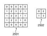
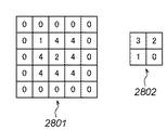
図25、図26、図27、図28、図29はそれぞれ、本実施形態におけるマッチングパターン2501、2601、2701、2801、2901と画素置き換えパターン2502、2602、2702、2802、2902の一例を示す図である。マッチングパターンにはそれぞれインデックスが付けられており、実施形態1で示したものと同様に画素置き換えパターンと対応付けて準備され管理される。
25, 26, 27, 28, and 29 are diagrams showing examples of the
マッチングパターン2501、2601、2701、2801、2901については実施形態1と同様であるため、詳細な説明は省略する。
Since the
画素置き換えパターン2502、2602、2702、2802、2902は、2×2のマトリックスで与えられ、マトリックスの位置に対応した0〜3までの置き換え順位(0が優先)がそれぞれに与えられている。
The
なお、本実施形態における上述の画素置き換えパターンに与えられた順位は0〜3に限定するものではなく、マトリックスの位置に対応した順位がそれぞれわかるものであれば、本実施形態は有効である。 The order given to the above-described pixel replacement pattern in the present embodiment is not limited to 0 to 3, and the present embodiment is effective as long as the order corresponding to the position of the matrix is known.
(画素の置き換え処理S2411の具体例)
次に、前述の画素の置き換え処理S2411について、図30、図31、図32を用いて説明する。
(Specific example of pixel replacement processing S2411)
Next, the above-described pixel replacement process S2411 will be described with reference to FIGS. 30, 31, and 32. FIG.
図30の矢印左側は、図17に示す3値化されたウィンドウ1701と、図25のマッチングパターン2501を180度回転し転置した状態で一致するため、対応する画素置き換えパターン2502を回転、転置した画素置き換えパターン3001とを示す。図30の矢印右側は、画素置き換え処理によって生成された1200dpiの4画素のビットマップデータ3002である。ウィンドウ1701は、背景/最大画素値検索処理S2403において背景画素値0、最大画素値aであり、出力画素数の算出S2405において出力画素数3とされている。このため、画素置き換えパターン3001のマトリックスに配置された順位に従ってマトリックス状に画素を配置して、ビットマップデータ3002を生成する。
The left side of the arrow in FIG. 30 matches the
図31の矢印左側は、図18に示す3値化されたウィンドウ1801と、図26のマッチングパターン2601が一致したため、マッチングパターン2601に対応付けられている画素置き換えパターン2602とを示す。図31の矢印右側は、画素置き換え処理によって生成された1200dpiの4画素のビットマップデータ3101である。ウィンドウ1801は、背景/最大画素値検索処理S2403において背景画素値0、最大画素値aであり、出力画素数の算出S2405において出力画素数1とされている。そのため、画素置き換えパターン2602のマトリックスに配置された順位に従ってマトリックス状に画素を配置して、ビットマップデータ3101を生成する。
The left side of the arrow in FIG. 31 shows the
図32の矢印左側は、図19に示す3値化されたウィンドウ1901と、180度回転した画素置き換えパターン3201とを示す。この例では、図29に示すマッチングパターン2901が180度回転した状態で一致したため、対応する画素置き換えパターン2902を同様に180度回転している。図32の矢印右側は、画素置き換え処理によって生成された1200dpi4画素のビットマップデータ3202である。ウィンドウ1901は、背景/最大画素値検索処理S2403において背景画素値0、最大画素値aであり、出力画素数の算出S2405において出力画素数2とされている。そのため、画素置き換えパターン3201のマトリックスに配置された順位に従ってマトリックス状に画素を配置して、ビットマップデータ3202生成する。
The left side of the arrow in FIG. 32 shows a
(出力画素の順位付けの例)
次に、前述の出力画素の順位付けについて、図33、図34を用いて説明する。
(Example of ranking output pixels)
Next, the above-described output pixel ranking will be described with reference to FIGS. 33 and 34. FIG.
図33は、図2から擬似高解像度変換処理により生成された図4中で、画素座標(12,2)を注目画素としたときのウィンドウである。図33は、実施形態1で説明した画素401、画素402、画素403、画素404、画素405でウィンドウを構成している。図33のウィンドウは、図24のマッチングS2409において、本実施形態における一例として挙げた図25、図26、図27、図28、図29のマッチングパターンのいずれにも一致しない。そのため、出力画素の順位付けS2412において、ウィンドウ内の画素値に基づいてウィンドウの注目画素を中心とした左上、右上、右下、左下の総和を求め、それらの大きさによって出力画素の順位付けを行い、画素置き換えパターンを生成する。
FIG. 33 is a window when the pixel coordinate (12, 2) is the target pixel in FIG. 4 generated by the pseudo high resolution conversion process from FIG. In FIG. 33, the
本実施形態における出力画素の順位付けの一例を説明する。 An example of ranking output pixels in the present embodiment will be described.
図33におけるウィンドウのある画素位置を(i,j)、そのときの画素値をD(i,j)とする。その場合、ウィンドウの注目画素を中心とした左上の総和であるSUMupper-leftと、右上の総和であるSUMupper-rightと、右下の総和であるSUMlower-rightと、左下の総和であるSUMlower-leftは以下の式で求められる。
SUMupper-left =D(1,1)+D(2,1)+D(1,2)
SUMupper-right=D(2,1)+D(3,1)+D(3,2)
SUMlower-right=D(3,2)+D(2,3)+D(3,3)
SUMlower-left =D(1,2)+D(1,3)+D(2,3)
したがって、図33においてSUMupper-left=5a/4、SUMupper-right=0、SUMlower-right=a/2、SUMlower-left=2aとなる。
The pixel position in the window in FIG. 33 is (i, j), and the pixel value at that time is D (i, j). In that case, SUMupper-left which is the sum of the upper left centered on the pixel of interest of the window, SUMupper-right which is the sum of the upper right, SUMlower-right which is the sum of the lower right, and SUMlower-left which is the sum of the lower left. Is obtained by the following equation.
SUMupper-left = D (1,1) + D (2,1) + D (1,2)
SUMupper-right = D (2,1) + D (3,1) + D (3,2)
SUMlower-right = D (3,2) + D (2,3) + D (3,3)
SUMlower-left = D (1,2) + D (1,3) + D (2,3)
Therefore, in FIG. 33, SUMupper-left = 5a / 4, SUMupper-right = 0, SUMlower-right = a / 2, and SUMlower-left = 2a.
上記式によって算出されたそれぞれの総和に基づいて、値の大きい順にそれぞれの総和の位置に対応した画素置き換えパターンの座標に順位を設定して画素置き換えパターンを生成する。よって、図33においては、SUMlower-left>SUMupper-left>SUMlower-right>SUMupper-rightとなるため、図34に示す画素置き換えパターンが生成される。 Based on each sum calculated by the above equation, a pixel replacement pattern is generated by setting the rank in the coordinates of the pixel replacement pattern corresponding to the position of each sum in descending order. Therefore, in FIG. 33, since SUMlower-left> SUMupper-left> SUMlower-right> SUMupper-right, the pixel replacement pattern shown in FIG. 34 is generated.
上記、ウィンドウの注目画素を中心とした左上の総和SUMupper-leftと、右上の総和SUMupper-rightと、右下の総和SUMlower-rightと、左下の総和SUMlower-leftの算出方法は、一例を示す図である。それぞれの順位付けが可能であれば、ウィンドウ内のどの画素位置を用いてそれぞれの値を求めても本実施形態は有効である。 The calculation method of the upper left sum SUMupper-left, the upper right sum SUMupper-right, the lower right sum SUMlower-right, and the lower left sum SUMlower-left centered on the target pixel of the window is shown as an example. It is. If each ranking is possible, this embodiment is effective even if each pixel position in the window is used to obtain each value.
なお、その他の構成、作用などは実施形態1と同様であるので、詳細な説明は省略する。 Since other configurations and operations are the same as those in the first embodiment, detailed description thereof is omitted.
(実施形態2の効果)
以上説明してきたように、本実施形態によれば、実施形態1と同様の効果が得られる。加えて、実施形態1の方法よりも処理量は増えるが、マッチングによって一致しない注目画素についても画素置き換えパターンを算出して置き換えが可能なことから、マッチングパターンの数を減らすことに繋がる。また、最大画素値と注目画素値とに基づいて出力画素値を算出するため、擬似高解像度変換処理された画素に対して変換前により近い状態へと、より柔軟に復元することができるようになる。
(Effect of Embodiment 2)
As described above, according to the present embodiment, the same effects as those of the first embodiment can be obtained. In addition, although the processing amount is larger than that of the method of the first embodiment, it is possible to calculate and replace a pixel replacement pattern for a pixel of interest that does not match due to matching, leading to a reduction in the number of matching patterns. In addition, since the output pixel value is calculated based on the maximum pixel value and the target pixel value, it can be more flexibly restored to a state closer to that before the conversion with respect to the pixel subjected to the pseudo high resolution conversion processing. Become.
<実施形態3の擬似高解像度変換処理部108の構成及び動作例>
本実施形態における装置の基本的な構成は、上述の実施形態1の説明に用いた図1と同様なため、詳細な説明は省略する。
<Configuration and Operation Example of Pseudo High Resolution
Since the basic configuration of the apparatus in the present embodiment is the same as that of FIG. 1 used in the description of the first embodiment, detailed description thereof is omitted.
以下、本実施形態の高解像度変換処理部108の構成及び動作例を詳細に説明する。
Hereinafter, a configuration and an operation example of the high resolution
本実施形態においては、実施形態1の間引き処理、置き換え処理に加えて、後述の平均化処理を行うものとする。 In this embodiment, in addition to the thinning process and replacement process of the first embodiment, an averaging process described later is performed.
(平均化処理例)
平均化処理は、1200dpiの入力画像の両座標ともに奇数である座標の画素を注目画素Din(i, j)とし、Din(i-1, j-1)、Din(i, j-1)、Din(i, j)内で注目画素と同じ属性データの画素の総和SUMを求める。そして、画素数Nをカウントする。その後、SUMをNで割って、600dpi1画素に対応する出力値とする。
この時、N数を出力画素に対応する属性データに付加する。
(Example of averaging process)
In the averaging process, a pixel having coordinates that are odd in both coordinates of the 1200 dpi input image is set as a target pixel Din (i, j), and Din (i-1, j-1), Din (i, j-1), The sum SUM of pixels having the same attribute data as the target pixel is obtained in Din (i, j). Then, the number of pixels N is counted. Then, SUM is divided by N to obtain an output value corresponding to 600
At this time, the N number is added to the attribute data corresponding to the output pixel.
(解像度変換の切り替え例)
上記処理は入力画像の1画素毎に対応する属性データ中の属性フラグに基づき適意切り替えて処理されるが、その一例を以下に示す。
(Resolution conversion switching example)
The above processing is performed by appropriately switching based on the attribute flag in the attribute data corresponding to each pixel of the input image. An example is shown below.
注目画素もしくは近傍の画素に対応する属性データにおいてイメージフラグがONのとき、もしくはフラグが無い場合、注目画素の間引き処理が選択される。また、グラフィックフラグが共にONの場合、最大画素値の置き換え処理が選択される。上記条件以外の場合は、注目画素の属性データに応じて平均化処理が行われる。 When the image flag is ON in the attribute data corresponding to the target pixel or a neighboring pixel, or when there is no flag, the target pixel thinning-out process is selected. When both graphic flags are ON, replacement processing for the maximum pixel value is selected. In cases other than the above conditions, an averaging process is performed according to the attribute data of the target pixel.
<実施形態3の高解像度変換処理部111の構成及び動作例>
以下、本実施形態の高解像度変換処理部111の構成及び動作例を詳細に説明する。
<Configuration and Operation Example of High Resolution
Hereinafter, a configuration and an operation example of the high resolution
本実施形態の高解像度変換処理は、実施形態2の高解像度変換処理とほぼ同様であるため差異のある部分のみ詳細に説明する。 Since the high resolution conversion process of the present embodiment is substantially the same as the high resolution conversion process of the second embodiment, only differences will be described in detail.
本実施形態では、ステップS2402において、フィルタ処理フラグではなく、平均化処理によって付加した画素数Nを用いて判定を行う。また、S2403の背景/最大画素値検索処理において、最大画素値は必要ないため背景画素値のみ検索する。また、S2404では、ハーフドット判定に画素数Nを用い、N=1,2,3の場合ハーフドットと判定する。また、S2405の出力画素数算出を行わず、出力画素数として前記擬似高解像度変換処理において属性データに付加した画素数Nを用いる。また、S2408の3値化処理では、画素数N=4のとき“3:最大画素”に、画素数N=1,2,3のとき“2:ハーフドット画素”に、それ以外を“1:背景画素”とする。また、S2411の画素置き換えパターンの置き換え処理で用いる最大画素値には、前記擬似高解像度変換処理で平均化された注目画素の値を用いる。 In this embodiment, in step S2402, determination is performed using the number N of pixels added by the averaging process, not the filter processing flag. Further, in the background / maximum pixel value search processing in S2403, only the background pixel value is searched because the maximum pixel value is not necessary. In S2404, the number N of pixels is used for half-dot determination, and when N = 1, 2, 3, it is determined as a half-dot. Further, the number of output pixels is not calculated in S2405, and the number of pixels N added to the attribute data in the pseudo high resolution conversion process is used as the number of output pixels. Further, in the ternarization processing of S2408, when the number of pixels N = 4, “3: maximum pixel”, when the number of pixels N = 1, 2, 3 is set to “2: half-dot pixel”, and other than “1” : Background pixel ”. Further, the value of the target pixel averaged in the pseudo high resolution conversion process is used as the maximum pixel value used in the pixel replacement pattern replacement process in S2411.
(実施形態3の効果)
以上説明してきたように、本実施形態によれば、実施形態2と同様の効果が得られる。加えて、実施形態2の方法よりも属性データのデータ量は増えるが、置き換え画素数の演算など、処理を大幅に減らすことが可能となる。
(Effect of Embodiment 3)
As described above, according to the present embodiment, the same effects as those of the second embodiment can be obtained. In addition, although the data amount of the attribute data is increased as compared with the method of the second embodiment, the processing such as the calculation of the number of replacement pixels can be significantly reduced.
<他の実施形態>
なお、本実施形態では、レンダリング部107でレンダリングされるビットイメージのビット数を8bitとしているが、階調を再現するに十分なビット数であれば、他のビット数(例えば10bit)であっても、本発明は有効となる。
<Other embodiments>
In this embodiment, the bit number of the bit image rendered by the
また、本実施形態では、レンダリング部107でレンダリングされるビットイメージの解像度を1200dpi、擬似高解像度変換処理部108で擬似高解像度変換処理されて生成されるビットイメージの解像度を600dpiとした。しかし、上記の条件に限定するものではない。レンダリング部107で生成されるビットイメージの解像度を解像度A、擬似高解像度変換処理部108で生成されるビットイメージの解像度を解像度Bとする。この場合に、解像度Aと解像度Bとの関係が解像度A > 解像度Bであって、解像度Aは解像度Bの整数倍nであれば、本発明は有効となる。また、その際には画素置き換えパターンのサイズをn×nとしておくことが必要となることは言うまでもない。
In this embodiment, the resolution of the bit image rendered by the
また、本実施形態では、擬似高解像度変換処理において、属性フラグに基づいてイメージフラグもしくはグラフィックフラグがONのとき注目画素の間引き処理を選択した。また、小フォントフラグが共にONのとき最大画素値の置き換え処理を選択した。また、それ以外の場合は注目画素の画素値に応じた重み付け係数のフィルタが選択されてフィルタ処理が行われるとした。しかし、この組み合わせに限定するものではなく、異なる組み合わせや異なる属性フラグにおいて種々の擬似高解像度変換処理を切り替えて実施されても、本発明は有効となる。 Further, in this embodiment, in the pseudo high resolution conversion process, the pixel-of-interest thinning process is selected based on the attribute flag when the image flag or the graphic flag is ON. Further, when both the small font flags are ON, the replacement process of the maximum pixel value is selected. In other cases, a filter having a weighting coefficient corresponding to the pixel value of the target pixel is selected and the filter process is performed. However, the present invention is not limited to this combination, and the present invention is effective even when various pseudo high-resolution conversion processes are performed with different combinations and different attribute flags.
また、マッチングパターン、画素置き換えパターン、3値化処理の数値はこれに限定するものではなく、同じ役割を持てばどのような組合せであっても、本発明は有効となる。 In addition, the numerical values of the matching pattern, the pixel replacement pattern, and the ternary processing are not limited to this, and the present invention is effective in any combination as long as it has the same role.
また、本実施形態において、マッチングパターン、画素置き換えパターンは5つとしているが、個数について限定するものではなく、いくつのパターンを有していても、本発明は有効となる。 In the present embodiment, the number of matching patterns and pixel replacement patterns is five. However, the number of patterns is not limited, and the present invention is effective with any number of patterns.
また、本実施形態では、高解像度変換処理におけるウィンドウサイズを(5×5)画素としている。しかし、ウィンドウサイズが本実施形態より大きい、もしくは小さい場合でも、本発明は有効となる。また、ラインバッファのライン数やマッチングパターンのサイズをウィンドウのサイズに応じて変更させる必要があることは言うまでもない。 In the present embodiment, the window size in the high resolution conversion process is set to (5 × 5) pixels. However, the present invention is effective even when the window size is larger or smaller than this embodiment. It goes without saying that the number of lines in the line buffer and the size of the matching pattern need to be changed according to the size of the window.
また、本実施形態では、上記画像処理をソフトウエアで行うように記載している。しかし、SOC(システムオンチップ)やFPGAなどのハードに実装して行っても、本発明は有効である。また、高解像度処理部におけるマッチングなどのシームレスな動作をパイプライン化して動作させても、本発明は有効となる。 In the present embodiment, the image processing is described as being performed by software. However, the present invention is effective even when mounted on hardware such as SOC (system on chip) or FPGA. Further, the present invention is effective even when a seamless operation such as matching in the high resolution processing unit is performed in a pipeline.
また、本発明は、複数の機器から構成されるシステムに適用しても良いし、また、1つの機器からなる装置に適用しても良い。 Further, the present invention may be applied to a system composed of a plurality of devices, or may be applied to an apparatus composed of one device.
また、本発明の目的は前述した実施形態の機能を実現するソフトウェアのプログラムコードを記録した記憶媒体を、システム或いは装置に供給する。そして、そのシステム或いは装置のコンピュータ(CPU若しくはMPU)が記憶媒体に格納されたプログラムコードを読出し実行することによっても、達成されることは言うまでもない。 Also, an object of the present invention is to supply a storage medium that records a program code of software that realizes the functions of the above-described embodiments to a system or apparatus. Needless to say, this can also be achieved by the computer (CPU or MPU) of the system or apparatus reading and executing the program code stored in the storage medium.
この場合、記憶媒体から読出されたプログラムコード自体が前述した実施形態の機能を実現することになり、そのプログラムコードを記憶した記憶媒体は本発明を構成することになる。 In this case, the program code itself read from the storage medium realizes the functions of the above-described embodiments, and the storage medium storing the program code constitutes the present invention.
このプログラムコードを供給するための記憶媒体としては、例えばフロッピー(登録商標)ディスク、ハードディスク、光ディスク、光磁気ディスク、CD-ROM、CD-R、磁気テープ、不揮発性のメモリカード、ROMなどを用いることができる。 As a storage medium for supplying the program code, for example, a floppy (registered trademark) disk, a hard disk, an optical disk, a magneto-optical disk, a CD-ROM, a CD-R, a magnetic tape, a nonvolatile memory card, a ROM, or the like is used. be able to.
また、コンピュータが読出したプログラムコードを実行することにより、前述した実施形態の機能が実現されるだけではない。そのプログラムコードの指示に基づき、コンピュータ上で稼働しているOS(オペレーティングシステム)などが実際の処理の一部又は全部を行い、その処理によって前述した実施形態の機能が実現される場合も含まれることは言うまでもない。 In addition, the functions of the above-described embodiments are not only realized by executing the program code read by the computer. This includes the case where an OS (operating system) running on a computer performs part or all of the actual processing based on the instruction of the program code, and the functions of the above-described embodiments are realized by the processing. Needless to say.
更に、記憶媒体から読出されたプログラムコードが、コンピュータに挿入された機能拡張ボードやコンピュータに接続された機能拡張ユニットに備わるメモリに書込まれる。その後、そのプログラムコードの指示に基づき、その機能拡張ボードや機能拡張ユニットに備わるCPUなどが実際の処理の一部又は全部を行い、その処理によって前述した実施形態の機能が実現される場合も含まれることは言うまでもない。 Further, the program code read from the storage medium is written in a memory provided in a function expansion board inserted into the computer or a function expansion unit connected to the computer. After that, based on the instruction of the program code, the CPU of the function expansion board or function expansion unit performs part or all of the actual processing, and the function of the above-described embodiment is realized by the processing. Needless to say.
Claims (22)
前記第1解像度の多値画像から前記第2解像度の多値画像への変換では、該変換前の画素の属性フラグに対応する変換を行い、当該対応した変換を施したことを示す変換処理フラグを該変換後の画素データに対応付けて保持する保持工程と、
前記第2解像度の多値画像から前記第1解像度の多値画像への復元では、前記第2解像度の多値画像の注目画素と該注目画素の周囲の画素に対応付けて保持された前記変換処理フラグを用いて、該注目画素の画素データを複数画素からなる画素データに置き換える置換工程と、を有し、
前記属性フラグに対応する変換がフィルタ処理の場合には、
前記変換処理フラグは、フィルタ処理による解像度変換を施したことを示すフィルタ処理フラグと、該フィルタ処理を施した後の画素値が該フィルタ処理以前の画素値よりも小さくなったことを示すハーフドットフラグとを含み、前記第2解像度の多値画像から前記第1解像度の多値画像への復元において、前記置換工程は、前記注目画素と該注目画素の周囲の画素の前記フィルタ処理フラグと前記ハーフドットフラグとを用いて、予め定められたパターンとのパターンマッチングを行い、該注目画素の画素データを複数画素からなる画素データに置き換える、
ことを特徴とする画像処理方法。 An image processing method for restoring a first multi-value image from a second multi-value image after converting a first multi-value image into a second multi-value image lower than the first resolution. There,
In the first resolution conversion from multi-value image to the second resolution of the multi-valued image, it performs conversion corresponding to the attribute flag of the pre-conversion pixel conversion process flag indicating that subjected to conversion to the corresponding Holding in association with the converted pixel data ,
In the restoration from the multi-value image of the second resolution to the multi-value image of the first resolution, the conversion held in association with the target pixel of the multi-value image of the second resolution and the surrounding pixels of the target pixel Replacing the pixel data of the target pixel with pixel data consisting of a plurality of pixels using a processing flag ,
When the conversion corresponding to the attribute flag is a filtering process,
The conversion processing flag includes a filtering flag indicating that resolution conversion has been performed by filtering, and a half dot indicating that the pixel value after the filtering is smaller than the pixel value before the filtering In the restoration from the second resolution multi-valued image to the first resolution multi-valued image, the replacement step includes the filtering process flag of the pixel of interest and pixels around the pixel of interest, and the Perform pattern matching with a predetermined pattern using a half-dot flag, and replace pixel data of the target pixel with pixel data composed of a plurality of pixels.
An image processing method.
前記フィルタ処理フラグ及び前記ハーフドットフラグがONで、前記注目画素を含む予め決められたウィンドウ内の画素データの配置と前記予め定められたパターンとのパターンマッチングが取れた場合には、該注目画素が前記予め定められたパターンに対応付けられた複数の画素の出力順位に対応して前記出力画素数だけの画素データに置き換え、
前記フィルタ処理フラグ及び前記ハーフドットフラグがONで、前記注目画素を含む予め決められたウィンドウ内の画素データの配置と前記予め定められたパターンとのパターンマッチングが取れない場合には、該注目画素の周辺画素の画素データに対応して複数の画素の出力順位を設定し、該出力順位に対応して前記出力画素数だけの画素データに置き換え、
前記フィルタ処理フラグがOFF又は前記ハーフドットフラグがOFFの場合には、前記注目画素の画素データの値を維持して複数の画素の画素データに置き換える、ことを特徴とする請求項1に記載の画像処理方法。 In the restoration from the multi-valued image of the second resolution to the multi-valued image of the first resolution, the number of output pixels to be output corresponding to the target pixel is calculated,
The filtering flag and the half dot flag is ON, when the pattern matching between the predetermined pattern and the arrangement of pixel data within a predetermined window including the pixel of interest has been established, the target pixel There replaced with pixel data of only the number of the output pixels corresponding to the output order of the plurality of pixels associated with said predetermined pattern,
The filtering flag and the half dot flag is ON, when the pattern matching predetermined including the pixel of interest and the arrangement of pixel data in the window with the predetermined pattern can not be taken, the target pixel Set the output order of a plurality of pixels corresponding to the pixel data of the surrounding pixels, and replace with pixel data of the number of output pixels corresponding to the output order,
Wherein when filtering flag is OFF or the half dot flag OFF, according to claim 1, wherein while maintaining the value of the pixel data of the target pixel replaced with pixel data of a plurality of pixels, characterized in that Image processing method.
前記第1解像度の多値画像から前記第2解像度の多値画像への変換では、該変換前の画素の属性フラグに対応する変換を行い、当該対応した変換を施したことを示す変換処理フラグを該変換後の画素データに対応付けて保持する保持手段と、
前記第2解像度の多値画像から前記第1解像度の多値画像への復元では、前記第2解像度の多値画像の注目画素と該注目画素の周囲の画素に対応付けて保持された前記変換処理フラグを用いて、該注目画素の画素データを複数画素からなる画素データに置き換える置換手段と、を有し、
前記属性フラグに対応する変換がフィルタ処理の場合には、
前記変換処理フラグは、フィルタ処理による解像度変換を施したことを示すフィルタ処理フラグと、該フィルタ処理を施した後の画素値が該フィルタ処理以前の画素値よりも小さくなったことを示すハーフドットフラグとを含み、前記第2解像度の多値画像から前記第1解像度の多値画像への復元において、前記置換手段は、前記注目画素と該注目画素の周囲の画素の前記フィルタ処理フラグと前記ハーフドットフラグとを用いて、予め定められたパターンとのパターンマッチングを行い、該注目画素の画素データを複数画素からなる画素データに置き換える、
ことを特徴とする画像処理装置。 An image processing apparatus for restoring a first multi-value image from a second multi-value image after converting a first multi-value image into a second multi-value image lower than the first resolution. There,
In the first resolution conversion from multi-value image to the second resolution of the multi-valued image, it performs conversion corresponding to the attribute flag of the pre-conversion pixel conversion process flag indicating that subjected to conversion to the corresponding Holding means for holding the pixel data in association with the converted pixel data ;
In the restoration from the multi-value image of the second resolution to the multi-value image of the first resolution, the conversion held in association with the target pixel of the multi-value image of the second resolution and the surrounding pixels of the target pixel Replacement means for replacing pixel data of the target pixel with pixel data composed of a plurality of pixels using a processing flag ,
When the conversion corresponding to the attribute flag is a filtering process,
The conversion processing flag includes a filtering flag indicating that resolution conversion has been performed by filtering, and a half dot indicating that the pixel value after the filtering is smaller than the pixel value before the filtering In the restoration from the second resolution multi-value image to the first resolution multi-value image, the replacement means includes the filter processing flag of the pixel of interest and pixels around the pixel of interest, and the Perform pattern matching with a predetermined pattern using a half-dot flag, and replace pixel data of the target pixel with pixel data composed of a plurality of pixels.
An image processing apparatus.
前記フィルタ処理フラグ及び前記ハーフドットフラグがONで、前記注目画素を含む予め決められたウィンドウ内の画素データの配置と前記予め定められたパターンとのパターンマッチングが取れた場合には、該注目画素が前記予め定められたパターンに対応付けられた複数の画素の出力順位に対応して前記出力画素数だけの画素データに置き換え、
前記フィルタ処理フラグ及び前記ハーフドットフラグがONで、前記注目画素を含む予め決められたウィンドウ内の画素データの配置と前記予め定められたパターンとのパターンマッチングが取れない場合には、該注目画素の周辺画素の画素データに対応して複数の画素の出力順位を設定し、該出力順位に対応して前記出力画素数だけの画素データに置き換え、
前記フィルタ処理フラグがOFF又は前記ハーフドットフラグがOFFの場合には、前記注目画素の画素データの値を維持して複数の画素の画素データに置き換える、ことを特徴とする請求項10に記載の画像処理装置。 In the restoration from the multi-valued image of the second resolution to the multi-valued image of the first resolution, the number of output pixels to be output corresponding to the target pixel is calculated,
The filtering flag and the half dot flag is ON, when the pattern matching between the predetermined pattern and the arrangement of pixel data within a predetermined window including the pixel of interest has been established, the target pixel There replaced with pixel data of only the number of the output pixels corresponding to the output order of the plurality of pixels associated with said predetermined pattern,
The filtering flag and the half dot flag is ON, when the pattern matching predetermined including the pixel of interest and the arrangement of pixel data in the window with the predetermined pattern can not be taken, the target pixel Set the output order of a plurality of pixels corresponding to the pixel data of the surrounding pixels, and replace with pixel data of the number of output pixels corresponding to the output order,
Wherein when filtering flag is OFF or the half dot flag OFF, according to claim 10, wherein while maintaining the value of the pixel data of the target pixel replaced with pixel data of a plurality of pixels, characterized in that Image processing device.
フィルタ処理による解像度変換を施したことを示すフィルタ処理フラグと、該フィルタ処理を施した後の画素値が該フィルタ処理以前の画素値よりも小さくなったことを示すハーフドットフラグとが付加された前記第2解像度の画像データを入力する入力工程と、A filter processing flag indicating that resolution conversion has been performed by the filter processing and a half dot flag indicating that the pixel value after the filter processing is smaller than the pixel value before the filter processing are added. An input step of inputting the image data of the second resolution;
該入力された前記第2解像度の画像データ中の注目画素と該注目画素の周囲の画素とに付加された前記フィルタ処理フラグと前記ハーフドットフラグとを用いて、予め定められたパターンとのパターンマッチングを行い、前記注目画素の画素データを複数画素からなる画素データに置き換えることで前記第1解像度の画像を生成する生成工程と、A pattern of a predetermined pattern using the filter processing flag and the half-dot flag added to the target pixel in the input image data of the second resolution and the pixels around the target pixel Generating a first resolution image by performing matching and replacing the pixel data of the target pixel with pixel data composed of a plurality of pixels;
を有することを特徴とする画像処理方法。 An image processing method comprising:
フィルタ処理による解像度変換を施したことを示すフィルタ処理フラグと、該フィルタ処理を施した後の画素値が該フィルタ処理以前の画素値よりも小さくなったことを示すハーフドットフラグとが付加された前記第2解像度の画像データを入力する入力手段と、A filter processing flag indicating that resolution conversion has been performed by the filter processing and a half dot flag indicating that the pixel value after the filter processing is smaller than the pixel value before the filter processing are added. Input means for inputting the image data of the second resolution;
該入力された前記第2解像度の画像データ中の注目画素と該注目画素の周囲の画素とに付加された前記フィルタ処理フラグと前記ハーフドットフラグとを用いて、予め定められたパターンとのパターンマッチングを行い、前記注目画素の画素データを複数画素からなる画素データに置き換えることで前記第1解像度の画像を生成する生成手段と、A pattern of a predetermined pattern using the filter processing flag and the half-dot flag added to the target pixel in the input image data of the second resolution and the pixels around the target pixel Generating means for generating an image of the first resolution by performing matching and replacing pixel data of the target pixel with pixel data composed of a plurality of pixels;
を有することを特徴とする画像処理装置。 An image processing apparatus comprising:
Priority Applications (3)
| Application Number | Priority Date | Filing Date | Title |
|---|---|---|---|
| JP2007082740A JP5089214B2 (en) | 2007-03-27 | 2007-03-27 | Image processing method and apparatus, computer program, and storage medium |
| US12/052,664 US8331731B2 (en) | 2007-03-27 | 2008-03-20 | Image processing method and image processing apparatus |
| CN2008100848250A CN101277365B (en) | 2007-03-27 | 2008-03-27 | Image processing device and image processing method |
Applications Claiming Priority (1)
| Application Number | Priority Date | Filing Date | Title |
|---|---|---|---|
| JP2007082740A JP5089214B2 (en) | 2007-03-27 | 2007-03-27 | Image processing method and apparatus, computer program, and storage medium |
Publications (3)
| Publication Number | Publication Date |
|---|---|
| JP2008238590A JP2008238590A (en) | 2008-10-09 |
| JP2008238590A5 JP2008238590A5 (en) | 2010-01-07 |
| JP5089214B2 true JP5089214B2 (en) | 2012-12-05 |
Family
ID=39910505
Family Applications (1)
| Application Number | Title | Priority Date | Filing Date |
|---|---|---|---|
| JP2007082740A Expired - Fee Related JP5089214B2 (en) | 2007-03-27 | 2007-03-27 | Image processing method and apparatus, computer program, and storage medium |
Country Status (3)
| Country | Link |
|---|---|
| US (1) | US8331731B2 (en) |
| JP (1) | JP5089214B2 (en) |
| CN (1) | CN101277365B (en) |
Families Citing this family (19)
| Publication number | Priority date | Publication date | Assignee | Title |
|---|---|---|---|---|
| US8675998B2 (en) * | 2007-12-06 | 2014-03-18 | Mitsubishi Electric Corporation | Method and apparatus for high frequency component smoothing, and image display apparatus |
| JP4650500B2 (en) * | 2008-02-25 | 2011-03-16 | コニカミノルタビジネステクノロジーズ株式会社 | Image processing apparatus and image processing method |
| JP5147597B2 (en) | 2008-08-13 | 2013-02-20 | キヤノン株式会社 | Image forming apparatus, image forming method, and program |
| JP5241429B2 (en) * | 2008-10-24 | 2013-07-17 | キヤノン株式会社 | Image forming apparatus and control method thereof |
| JP5254739B2 (en) * | 2008-10-24 | 2013-08-07 | キヤノン株式会社 | Image forming apparatus and control method thereof |
| JP5564806B2 (en) | 2009-03-11 | 2014-08-06 | 株式会社リコー | Image forming apparatus, image forming method, image forming program, and recording medium |
| JP5597968B2 (en) | 2009-07-01 | 2014-10-01 | ソニー株式会社 | Image processing apparatus and method, program, and recording medium |
| JP2012019357A (en) | 2010-07-07 | 2012-01-26 | Canon Inc | Image processing device and compression method |
| US9248525B2 (en) * | 2012-06-27 | 2016-02-02 | Mitsubishi Electric Research Laboratories, Inc. | Method and system for cutting features from sheet materials with a laser cutter according to a pattern |
| JP6099961B2 (en) | 2012-12-18 | 2017-03-22 | キヤノン株式会社 | Image display apparatus, image display apparatus control method, and computer program |
| JP2014139776A (en) * | 2012-12-19 | 2014-07-31 | Canon Inc | Display controller, display control method, and program |
| US9564186B1 (en) * | 2013-02-15 | 2017-02-07 | Marvell International Ltd. | Method and apparatus for memory access |
| JP5660187B2 (en) * | 2013-10-21 | 2015-01-28 | 株式会社リコー | Image forming apparatus, image forming method, image forming program, and recording medium |
| JP6165112B2 (en) | 2014-07-30 | 2017-07-19 | 京セラドキュメントソリューションズ株式会社 | Image forming apparatus |
| CN104835440B (en) * | 2015-05-22 | 2017-08-29 | 京东方科技集团股份有限公司 | Display methods, the display device of image |
| CN108833975B (en) * | 2016-03-18 | 2021-05-18 | 海信视像科技股份有限公司 | Video playing processing method and device |
| JP6824052B2 (en) | 2017-01-25 | 2021-02-03 | キヤノン株式会社 | Image processing device, its control method, and program |
| CN109993761B (en) | 2018-06-29 | 2021-04-09 | 长城汽车股份有限公司 | Ternary image acquisition method and device and vehicle |
| CN116055684B (en) * | 2023-01-18 | 2023-12-12 | 广州乐体科技有限公司 | Online physical education system based on picture monitoring |
Family Cites Families (37)
| Publication number | Priority date | Publication date | Assignee | Title |
|---|---|---|---|---|
| JPS54150022A (en) * | 1978-05-18 | 1979-11-24 | Ricoh Co Ltd | Method and apparatus for picture encoding reproduction |
| US4414580A (en) * | 1981-06-01 | 1983-11-08 | Bell Telephone Laboratories, Incorporated | Progressive transmission of two-tone facsimile |
| US4437122A (en) * | 1981-09-12 | 1984-03-13 | Xerox Corporation | Low resolution raster images |
| JPH0777418B2 (en) * | 1986-03-17 | 1995-08-16 | 株式会社東芝 | Image processing device |
| US4873577A (en) * | 1988-01-22 | 1989-10-10 | American Telephone And Telegraph Company | Edge decomposition for the transmission of high resolution facsimile images |
| JPH02250464A (en) * | 1989-03-24 | 1990-10-08 | Sharp Corp | Facsimile equipment |
| US4979049A (en) * | 1989-06-01 | 1990-12-18 | At&T Bell Laboratories | Efficient encoding/decoding in the decomposition and recomposition of a high resolution image utilizing its low resolution replica |
| US5031053A (en) * | 1989-06-01 | 1991-07-09 | At&T Bell Laboratories | Efficient encoding/decoding in the decomposition and recomposition of a high resolution image utilizing pixel clusters |
| JP3060569B2 (en) | 1991-04-04 | 2000-07-10 | セイコーエプソン株式会社 | Printing equipment |
| JP2898785B2 (en) | 1991-05-14 | 1999-06-02 | 京セラ株式会社 | High density image forming method |
| JP3221997B2 (en) * | 1993-03-26 | 2001-10-22 | 株式会社東芝 | Image processing device |
| JP3310744B2 (en) * | 1993-12-22 | 2002-08-05 | 東芝テック株式会社 | Resolution converter |
| US6289137B1 (en) * | 1994-06-02 | 2001-09-11 | Canon Kabushiki Kaisha | Image processing apparatus and method |
| US5526468A (en) * | 1995-03-27 | 1996-06-11 | Lexmark International, Inc. | Method and apparatus for smoothing an expanded bitmap for two-state image data |
| US5917952A (en) * | 1995-09-20 | 1999-06-29 | Hewlett-Packard Company | Compression of randomly dithered bi-level images |
| JP3581477B2 (en) * | 1996-03-04 | 2004-10-27 | 株式会社リコー | Digital copier |
| US5956470A (en) * | 1997-09-25 | 1999-09-21 | Xerox Corporation | Text quality enhancement via resolution enhancement technique based on separating jaggedness detection and filtering |
| US6020979A (en) * | 1998-03-23 | 2000-02-01 | Xerox Corporation | Method of encoding high resolution edge position information in continuous tone image information |
| JP2000011161A (en) * | 1998-06-26 | 2000-01-14 | Dainippon Screen Mfg Co Ltd | Image processor |
| JP2000151991A (en) * | 1998-11-12 | 2000-05-30 | Murata Mach Ltd | Image resolution conversion method and its device |
| JP2001169098A (en) * | 1999-09-27 | 2001-06-22 | Seiko Epson Corp | Medium recording output picture data correction program, output picture data correction method, output picture data correction device, medium recording picture data reduction program, picture data reduction method, picture data reduction device, medium recording picture data correction program and method and device for correcting picture data |
| JP2001105670A (en) * | 1999-10-13 | 2001-04-17 | Fuji Xerox Co Ltd | Imaging apparatus |
| JP2001119574A (en) * | 1999-10-14 | 2001-04-27 | Matsushita Graphic Communication Systems Inc | Image processing unit and image processing method |
| JP3964088B2 (en) * | 1999-12-28 | 2007-08-22 | 株式会社リコー | Image processing apparatus, image processing method, and computer-readable recording medium storing program for causing computer to execute the method |
| JP2001219601A (en) * | 2000-02-09 | 2001-08-14 | Canon Inc | Print controller and data processing method thereof |
| US7006244B2 (en) * | 2000-12-06 | 2006-02-28 | Xerox Corporation | Image rendering method and system using negative signals |
| JP2002207578A (en) * | 2001-01-09 | 2002-07-26 | Fuji Xerox Co Ltd | Image forming method and device |
| JP3940890B2 (en) * | 2001-09-17 | 2007-07-04 | 富士ゼロックス株式会社 | Image processing apparatus and image processing method |
| JP2003125401A (en) * | 2001-10-17 | 2003-04-25 | Mitsubishi Electric Corp | Video data reproducing method |
| US20050170183A1 (en) | 2002-04-26 | 2005-08-04 | Membrana Gmbh | Substituted polyarylether molded body, method for the production thereof and use of the same |
| JP3950839B2 (en) * | 2002-12-04 | 2007-08-01 | キヤノン株式会社 | Image processing apparatus and image processing method |
| JP2004242287A (en) * | 2003-01-14 | 2004-08-26 | Canon Inc | Information processing method and apparatus, computer program, and computer readable storage medium |
| JP4534505B2 (en) * | 2004-02-02 | 2010-09-01 | 富士ゼロックス株式会社 | Printing apparatus and raster image processor |
| JP4336859B2 (en) | 2004-06-15 | 2009-09-30 | 日本電気株式会社 | Redundant drive group and writing method and data restoring method using the same |
| JP4227569B2 (en) | 2004-07-07 | 2009-02-18 | キヤノン株式会社 | Image processing system, control method for image processing apparatus, program, and recording medium |
| JP2006168073A (en) * | 2004-12-14 | 2006-06-29 | Canon Inc | Inkjet recording system |
| US8520253B2 (en) * | 2005-03-22 | 2013-08-27 | Infoprint Solutions Company, Llc | Method and system for scaling with dot gain control |
-
2007
- 2007-03-27 JP JP2007082740A patent/JP5089214B2/en not_active Expired - Fee Related
-
2008
- 2008-03-20 US US12/052,664 patent/US8331731B2/en not_active Expired - Fee Related
- 2008-03-27 CN CN2008100848250A patent/CN101277365B/en not_active Expired - Fee Related
Also Published As
| Publication number | Publication date |
|---|---|
| CN101277365B (en) | 2011-03-02 |
| US20080310758A1 (en) | 2008-12-18 |
| US8331731B2 (en) | 2012-12-11 |
| JP2008238590A (en) | 2008-10-09 |
| CN101277365A (en) | 2008-10-01 |
Similar Documents
| Publication | Publication Date | Title |
|---|---|---|
| JP5089214B2 (en) | Image processing method and apparatus, computer program, and storage medium | |
| JP4495745B2 (en) | Image processing apparatus, image processing method, computer program, and storage medium | |
| JP2010171552A (en) | Image forming apparatus, control method, and program | |
| JP7005314B2 (en) | Image processing equipment, image processing methods, and programs | |
| JP6482265B2 (en) | Method and program for generating dither threshold matrix | |
| US8441690B2 (en) | Image processing apparatus and image processing method for processing screen-processed image | |
| JP5476874B2 (en) | Color processing apparatus, image forming apparatus, and program | |
| US9542130B2 (en) | Mask based toner reduction | |
| JPS60157375A (en) | Halftone expressing system | |
| JP3950839B2 (en) | Image processing apparatus and image processing method | |
| EP0723362B1 (en) | Colour image forming apparatus | |
| CN102035979A (en) | In place line splitting process and method for multiple beam printers | |
| WO2005109851A1 (en) | Image processing device, image processing method, and program | |
| JP4196782B2 (en) | Image processing apparatus and image processing program causing computer to execute image processing | |
| JP5678501B2 (en) | Image processing apparatus and image processing method | |
| JP6985943B2 (en) | Image processing device and its control method and program | |
| JP2000013601A (en) | Print information processor and device and method for generating intermediate data | |
| JP2015149719A (en) | Digital image halftone conversion with selective enhancement | |
| JP4636145B2 (en) | Image processing apparatus and program | |
| JP2014090272A (en) | Image processing method, image processing apparatus and program | |
| JP2019047275A (en) | Image forming method, image forming apparatus, and program | |
| JP2005045342A (en) | Image processing apparatus and image processing program for allowing computer to perform image processing | |
| JP2007118199A (en) | Screening method and image forming apparatus | |
| JPH114340A (en) | Image processor and image processing system | |
| JP2020195004A (en) | Image forming apparatus and control method for the same, and program |
Legal Events
| Date | Code | Title | Description |
|---|---|---|---|
| A521 | Request for written amendment filed |
Free format text: JAPANESE INTERMEDIATE CODE: A523 Effective date: 20091113 |
|
| A621 | Written request for application examination |
Free format text: JAPANESE INTERMEDIATE CODE: A621 Effective date: 20091113 |
|
| A131 | Notification of reasons for refusal |
Free format text: JAPANESE INTERMEDIATE CODE: A131 Effective date: 20120622 |
|
| A521 | Request for written amendment filed |
Free format text: JAPANESE INTERMEDIATE CODE: A523 Effective date: 20120821 |
|
| TRDD | Decision of grant or rejection written | ||
| A01 | Written decision to grant a patent or to grant a registration (utility model) |
Free format text: JAPANESE INTERMEDIATE CODE: A01 Effective date: 20120910 |
|
| A01 | Written decision to grant a patent or to grant a registration (utility model) |
Free format text: JAPANESE INTERMEDIATE CODE: A01 |
|
| A61 | First payment of annual fees (during grant procedure) |
Free format text: JAPANESE INTERMEDIATE CODE: A61 Effective date: 20120911 |
|
| FPAY | Renewal fee payment (event date is renewal date of database) |
Free format text: PAYMENT UNTIL: 20150921 Year of fee payment: 3 |
|
| R151 | Written notification of patent or utility model registration |
Ref document number: 5089214 Country of ref document: JP Free format text: JAPANESE INTERMEDIATE CODE: R151 |
|
| FPAY | Renewal fee payment (event date is renewal date of database) |
Free format text: PAYMENT UNTIL: 20150921 Year of fee payment: 3 |
|
| LAPS | Cancellation because of no payment of annual fees |