JP5084079B2 - A segmented architecture for detecting and identifying multiple sequences in fading channels - Google Patents
A segmented architecture for detecting and identifying multiple sequences in fading channels Download PDFInfo
- Publication number
- JP5084079B2 JP5084079B2 JP2001284240A JP2001284240A JP5084079B2 JP 5084079 B2 JP5084079 B2 JP 5084079B2 JP 2001284240 A JP2001284240 A JP 2001284240A JP 2001284240 A JP2001284240 A JP 2001284240A JP 5084079 B2 JP5084079 B2 JP 5084079B2
- Authority
- JP
- Japan
- Prior art keywords
- signal
- sequence
- signal identification
- symbols
- correlator
- Prior art date
- Legal status (The legal status is an assumption and is not a legal conclusion. Google has not performed a legal analysis and makes no representation as to the accuracy of the status listed.)
- Expired - Fee Related
Links
Images


Classifications
-
- H—ELECTRICITY
- H04—ELECTRIC COMMUNICATION TECHNIQUE
- H04B—TRANSMISSION
- H04B1/00—Details of transmission systems, not covered by a single one of groups H04B3/00 - H04B13/00; Details of transmission systems not characterised by the medium used for transmission
- H04B1/69—Spread spectrum techniques
- H04B1/707—Spread spectrum techniques using direct sequence modulation
- H04B1/7073—Synchronisation aspects
- H04B1/7075—Synchronisation aspects with code phase acquisition
- H04B1/70751—Synchronisation aspects with code phase acquisition using partial detection
- H04B1/70752—Partial correlation
-
- H—ELECTRICITY
- H04—ELECTRIC COMMUNICATION TECHNIQUE
- H04B—TRANSMISSION
- H04B1/00—Details of transmission systems, not covered by a single one of groups H04B3/00 - H04B13/00; Details of transmission systems not characterised by the medium used for transmission
- H04B1/69—Spread spectrum techniques
- H04B1/707—Spread spectrum techniques using direct sequence modulation
- H04B1/7073—Synchronisation aspects
- H04B1/7075—Synchronisation aspects with code phase acquisition
- H04B1/70751—Synchronisation aspects with code phase acquisition using partial detection
-
- H—ELECTRICITY
- H04—ELECTRIC COMMUNICATION TECHNIQUE
- H04B—TRANSMISSION
- H04B1/00—Details of transmission systems, not covered by a single one of groups H04B3/00 - H04B13/00; Details of transmission systems not characterised by the medium used for transmission
- H04B1/69—Spread spectrum techniques
- H04B1/707—Spread spectrum techniques using direct sequence modulation
- H04B1/709—Correlator structure
Description
【0001】
【発明の属する技術分野】
関連する主題は、本明細書と同時出願された以下の出願に開示されている:「フェージングチャネルにおいて信号を検出するためのセグメント化された相関器アーキテクチャ(Segmented Correlator Architecture For Signal Detection In Fading Channels)」と題する米国特許出願第09/665,511号。
本発明は通信に関し、特に無線通信に関する。
【0002】
【従来の技術】
無線通信は、移動通信局と基地局との間に音声またはデータの通信チャネルを作成することを含む。通信チャネルのセットアップには、通常、移動局が基地局によって監視されるアクセスチャネル上で既知のシーケンスを送信することを含む。基地局は既知のシーケンスを検出し、移動局と基地局との間のタイミング差推定等の機能にこれを用いる。
【0003】
移動局によりアクセスチャネルを介して基地局に送信される信号は、通常、S個のシンボルを含むM個の可能なシグネチャシーケンスのうちの1つに基づく既知のシーケンスを含む。このようなシステムの1つにおいては、M=16個の異なるシグネチャシーケンスを利用でき、各シグネチャシーケンスは、S=16個のシンボルを含む。UMTS W―CDMAは、16長ウォルシュ−アダマールシーケンスをシグネチャシーケンスとして用いる。これらシーケンスは当分野で周知であり、3GPP TSG RAN「拡散と変調(Spreading and Modulation)(FDD)」(TS25.213V3.2.b.)の第15、16頁に記載されている。16シンボルシグネチャシーケンスのうちの1つが選択されると、これを用いて、基地局に送信するシーケンスを生成する。図1は、どのように送信シーケンスが16シンボルシグネチャシーケンスから生成されるかを示したものである。シーケンス10は、シンボル期間12を有する16シンボルシグネチャシーケンスを表し、ここで各シンボルは+1または−1である。16シンボル期間はそれぞれCのチップすなわちサンプル期間14に分割され、この例ではC=256である。その結果、シグネチャシーケンスは総計Kのチップすなわちサンプル期間を含むことになり、ここではK=4,096である(S=16シンボル期間×シンボル期間当たりC=256のチップ期間)。シグネチャシーケンスを用いて、インタリーブドシーケンス18を生成する。インタリーブドシーケンスは256(K/C)の反復期間20を含み、該反復期間20はそれぞれ16(S)チップ期間22、総計で4,096(K)のチップ期間を有する。インタリーブドシーケンスは、シグネチャシーケンス10のシンボル期間0〜15の最初のチップ期間のシンボル値を用いて、インタリーブドシーケンス18の反復期間0の最初の16チップ期間を埋めることで作成される。インタリーブドシーケンス18の反復期間1のチップ期間は、シグネチャシーケンス10の16シンボル期間それぞれの二番目のチップ期間におけるシンボル値を用いて埋められる。同様に、インタリーブドシーケンス18の反復期間2のチップ期間は、シグネチャシーケンス10のシンボル期間0〜15の三番目のチップ期間におけるシンボル値を用いて埋められる。このプロセスは、最後の反復期間(反復期間255)の16チップ期間が、シグネチャシーケンス10の16シンボル期間それぞれの最後のチップ期間におけるシンボル値を用いて埋められるまで続けられる。その結果、インタリーブドシーケンス18は、16チップ期間をそれぞれ含む256反復期間からなる。各反復期間は、シグネチャシーケンス10の各シンボル期間からの1つのチップ期間の値に等しい値を有する16チップ期間を含む。したがって、シグネチャシーケンス10のシンボル期間0〜15のサンプルは、インタリーブドシーケンス18の各反復期間のチップ0〜15それぞれに含まれる。
【0004】
移動局から基地局に送信される既知のシーケンスを生成する際の最後のステップは、インタリーブドシーケンス18と4,096(K)チップ期間二値シーケンス24とのチップ期間ごとの乗算を行うことを含む。二値シーケンス24は既知であり、移動体が通信する特定の基地局に割り当てられる。チップ期間ごとの乗算の結果は送信シーケンス26であり、これが次に移動体によって基地局に送信される。
【0005】
可能な送信シーケンス26のセットは、移動体送信を受信することになる基地局に知れている。利用できるシグネチャシーケンス、二値シーケンス、およびインタリーブパターンは知られているため、可能な送信シーケンス26のセットもまた利用できる各シグネチャシーケンスごとに知れている。
【0006】
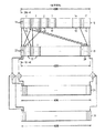
図2は、移動局によって送信され、基地局で受信される既知のシーケンスを識別し検出するために基地局によって用いられる多重信号検出器を示している。シフトレジスタ30は、受信したシーケンスのサンプルを受信する。シフトレジスタ30は、受信したシーケンスを構成する4,096のチップ期間に対応する4096のサンプルに備えるために、4,096(K)のロケーションを有する。受信したシーケンスを作成するために用いたインタリーブを考慮するため、シフトレジスタ30から相関器32、34、および36にサンプルを提供しながら、デインタリーブプロセスを実行する。各16チップ長反復期間の最初のチップ期間は、相関器32に提供されることに留意されたい。同様に、各16チップ長反復期間の二番目のチップ期間は、相関器34に提供される。このプロセスは、総計16の相関器について続けられ、16番目の相関器すなわち相関器36が各16チップ長反復期間の最後のチップを受信する。このデインタリーブプロセスは、各相関器にシンボル期間の256チップ期間サンプルを提供する。各相関器には、1つのシンボルを表す256チップ期間値に関連する一連の値を表す係数が提供されている。相関器に提供される一連の係数は、インタリーブドシーケンス18と二値シーケンス24との間のチップ期間ごとの乗算を考慮に入れたものであることに留意する。各相関器によって提供される出力は、シンボル期間からの256チップ期間値が+1または−1シンボルに予期される一連のチップ期間値にどの程度良好にマッチするかを示す。その結果、高速アダマール変換器(FHT)40が16個の相関器それぞれからの入力を受信する。ここで、各入力は、相関器によって検査される256チップ期間値がシンボルにどの程度良好に対応するか、およびその対応が+1シンボルであるか、または−1シンボルであるかを表す。
【0007】
FHTは当分野で周知であり、D. ElliotおよびK. Raoによる「高速変換:アルゴリズム、解析、応用(Fast transforms: algorithms, analysis, applications)」(Academic Press, Orlando, Florida, 1982)等の参照に記載されている。FHT40には、相関器から提供される出力に基づいて、可能な16のシグネチャシーケンスのいずれを受信しているかを識別するために用いられる係数が提供されている。FHTは、可能なシグネチャシーケンスのうちの1つにそれぞれ対応する16の出力を提供する。ここで、出力の大きさは、シフトレジスタ30におけるサンプルが各シーケンスにどの程度良好にマッチするかを示す。FHT40の出力はそれぞれ絶対値発生器42に提供される。該絶対値発生器42は、各FHTの出力の絶対値または絶対値の二乗をとる。絶対値発生器42の各出力は閾値器44に提供され、該閾値器44が絶対値発生器42からの値を所定の閾値と比較する。値が閾値を上回る場合、検出が宣言され、閾値超過信号を生成したFHT出力によって、受信したシーケンスが特定のシグネチャシーケンスに対応するものとして識別される。
【0008】
基地局が検索窓と呼ばれる時間期間でシーケンスを検出しようとすることに留意されたい。検索窓は、通常、受信したシーケンスのサンプル期間のN倍である。シフトレジスタ30は、初期サンプルセットで埋められると、N−1回新しいサンプルをシフトインすると共に、古いサンプルをシフトアウトする。この結果、シフトレジスタ30に提供されるサンプル間の時間期間をN倍したものに等しい検索窓にわたり、予期されるシーケンスの検出をN回試みることになる。検出されたシーケンスの検索窓における位置は、検出すべきシグネチャパターンに対応するFHTの出力の1つが閾値を越える場合に、シフトレジスタ30により行われるシフトの数によって決定される。検索窓における検出されたシーケンスの位置は、移動局と基地局との間の往復遅延の測度である。
【0009】
【発明が解決しようとする課題】
移動局が高速で移動中の自動車または列車内にある場合、シフトレジスタに供給される信号は高速フェージングを受ける。その結果、シフトレジスタが受信するシーケンスは部分的に破損し、低いFHT出力を生成する。その結果、閾値と比較するFHT出力は閾値を超えず、そのため受信したシグネチャシーケンスを検出または識別することができない。
【0010】
【課題を解決するための手段】
本発明は、セグメント化相関器およびFHT(高速アダマール変換)アーキテクチャを用いて、高速フェージング環境においてウォルシュ−ハダマードシーケンスおよびスクランブルシーケンスからなるシーケンス等、既知のシーケンスの検出および識別を提供する。サンプルまたはデータの入力シーケンスがブロックにセグメント化される。各ブロックは、相関器/FHTセグメントを用いて個々に検出される。各相関器/FHTセグメントの出力を識別する各シーケンスは、他の相関器/FHTセグメントの対応する出力と加算される。各和は閾値と比較され、特定のシーケンスが検出され識別されたかを判断する。
【0011】
【発明の実施の形態】
図3は、セグメント化されたシーケンス検出器/識別器の相関器/FHTセグメント50の機能ブロック図を示す。この例において、信号検出器/識別器は、図3に示すL=4のセグメントを含む。図4は、検出器/識別器を構成するLセグメント間の関係を示す。各Lセグメントは入力信号のK/Lサンプルを受信するが、但しKはそのシーケンスを含むチップ期間またはサンプルの数である。新しいサンプルが最初のセグメントにシフトインされると、最も古いサンプルが最初のセグメントからシフトアウトされ、二番目のセグメントにシフトインされる。同様に、残っているセグメントはそれぞれ先行セグメントから入力を受け取り、最も古いサンプルを次のセグメントにシフトアウトする。
【0012】
検出および識別プロセスは、入力信号のKサンプルの初期セットを受信した(すなわち、各セグメントがK/Lサンプルの初期セットを有する)後に開始する。図3に戻り、シフトレジスタ60は、受信したシーケンスの初期すなわちK/L(1024)サンプルを受信するが、但しLは検出器/識別器を構成するセグメントの数であり、基地局で移動局から受信したシーケンスを構成するチップ期間またはサンプルの数である(この例では、K=4096)。他の値のLを用いてもよく、Lの値が大きいほど、ハードウェアおよび/または処理を犠牲にして、高速フェージング環境においてパフォーマンスが改良される。受信シーケンスはシフトレジスタ60においてデインタリーブされ、相関器62、64〜66に提供される。デインタリーブは、シーケンスが移動局によって生成されたときに行われたあらゆるインタリーブ化を解除するために用いられる。送信されたシーケンスがインタリーブなしで生成された場合には、デインタリーブを省いてもよい。3つの相関器しか示さないが、この実施形態において、長さ64の16個の相関器を用いることに留意されたい。シグネチャシーケンスがS=16シンボルを含むものと前提するため、この例では16個の相関器を用いる。一般的に、相関器の数は、識別すべきシーケンスにおけるシンボルの数と一致すべきであり、相関器はC/Lの長さであるべきである。但し、Cはシグネチャシーケンスにおけるシンボル期間当たりのチップ期間の数である。この例では、C=256である。16シンボルの例に戻り、16チップ長の反復期間70それぞれの最初の期間のチップ値は、相関器62に提供され、16チップ長の反復期間70それぞれの二番目の期間のチップ値は相関器64に提供され、相関器66が16チップ長の反復期間70それぞれの最後のチップ値を受信するまで、同様にして残りの相関器が入力値で埋められる。相関器62、64、および66に提供される係数すなわち代表的なシンボルは、インタリーブドシーケンスと基地局関連の二値シーケンスとの間でのチップ期間ごとの乗算を考慮に入れた場合に予期されるC/L(64)チップ値シーケンスである。各相関器の出力は、相関器に提供されるC/Lチップ値が、+1または−1シンボルについて予期される一連のチップ期間値にどの程度良好にマッチするかを示す。相関器62、64、および66のシンボル相関器の出力は、16×16(S×M)FHT72に提供される。ここで、Sはシグネチャシーケンスにおけるシンボルの数であり、Mは受信可能な異なるシグネチャシーケンスの数である。相関器からの出力に基づいて、FHT72は、相関器からの信号相関入力によって表される信号が、16(M)個の可能なシグネチャシーケンスにどの程度良好に対応するかを示す16(M)個の信号識別出力それぞれについての出力値を提供する。たとえば、出力74は、レジスタ60におけるシーケンスが最初のシグネチャシーケンスにどの程度良好に対応するかを示す。同様に、出力76は、レジスタ60におけるシーケンスが二番目のシグネチャシーケンスにどの程度良好に対応するかを示す。最後に、出力78は、レジスタ60におけるシーケンスが16番目(M番目)のシグネチャシーケンスにどの程度良好に対応するかを示す。M個の可能なシグネチャシーケンスが識別される場合、M個の出力FHTを用いるべきであることに留意されたい。さらに、シンボル数SがMに等しいことが望ましい。図3に戻り、各FHTまたは信号識別出力は、絶対値発生器80およびマルチプレクサ82に提供される。絶対値発生器80は、FHT72からの出力の絶対値か、絶対値の二乗のいずれかを発生し、その値をマルチプレクサ82に提供する。マルチプレクサ82は、FHT72の出力か、または絶対値発生器80の出力を選択する。高速フェージング環境において信号の検出が試みられている場合には、絶対値発生器80の出力が選択される。深刻さのより低いフェージング環境において信号の検出が試みられている場合には、FHT72の出力が選択される。マルチプレクサ82の出力は、図4に示すように組み合わせられる。
【0013】
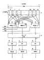
図4は、L=4の相関器/FHTセグメント50を組み合わせて、セグメント化されたシーケンス検出器/識別器を提供する様式を示す。各セグメント50は、図3に示す相関器/FHTセグメントに対応する。各セグメント50は、特定のシグネチャシーケンスにそれぞれ関連する16(M)個の信号識別出力を提供する。セグメント50からの出力は加算器110で加算され、各加算器は、特定のシグネチャシーケンスに関連する一群の出力を加算する。この例では、16(M)個の可能なシグネチャシーケンスがあるため、16個の加算器110がある。しかし、図を簡潔にするため、2個の加算器しか示さない。各加算器110の出力は、絶対値発生器112およびマルチプレクサ114に提供される。絶対値発生器は、加算器110によって生成される出力の絶対値、または絶対値の二乗を発生する。次に、絶対値発生器112の出力がマルチプレクサ114に提供される。マルチプレクサ114を用いて加算器110の出力と、絶対値発生器112の出力を選択する。高速フェージング環境では、マルチプレクサ114を用いて加算器110の出力を選択する。深刻さのより低いフェージング環境では、マルチプレクサ114を用いて絶対値発生器の出力を選択する。マルチプレクサ114の出力は閾値器116に提供され、閾値器116が、マルチプレクサの出力を所定の閾値と比較する。各シグネチャシーケンスに1つが関連する16(M)個の閾値116がある。閾値の1つが、入力が所定の閾値を超過することを示す場合、その閾値器に関連するシグネチャシーケンスが検出され、識別される。
【0014】
入力信号は、入力シフトレジスタ60を介し、セグメント50を通してシフトされて検査され、入力信号サンプル期間のN倍の検索窓が検査されるまで、既知のまたは予期されるシーケンスを検出/識別するよう試みる。これは、入力信号の初期Kサンプルを検査してから、Kサンプルの次の新しいN−1セットそれぞれを検査することで達成される。新しいKサンプルセットは、シフトレジスタ60が新しい入力信号サンプルをシフトインし、最も古いサンプルをシフトアウトする度に生成される。検出/識別されたシーケンスの検索窓における位置は、閾値器116による閾値を超過を検出したときに、シフトレジスタ60によって行われるシフトの数によって決定される。
【0015】
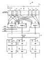
図5は、セグメント化された時分割多重アーキテクチャを用いる検出器/識別器アーキテクチャを示す。この例において、検索窓はサンプル期間のN個分の長さであり、NはK/L以下である。ここで、Kサンプルの入力シーケンスは長さK/LのL個のセグメントにセグメント化される。入力シフトレジスタ130は、各セグメントについてデータを左から右にN−1回シフトし、そうすることでNセットのK/Lサンプルを相関器132に提供する。この例において、シーケンスはS個のシンボルからなり、各シンボルはCのチップ期間を含む。したがって、それぞれ長さC/Lを有するS個の相関器を用いることが望ましい。この結果、相関器132は、各セグメントごとにNセットのSシンボル相関出力を生成することになる。この例では、L個の異なるセグメントがあるため、L個の異なる係数セットが相関器132に提供される。ここで、各係数セットは、代表的なシンボルの予期されるシーケンスセグメントまたはシーケンスを表す。最初のセグメントが相関器132に提供されると、最初のセットのK/L係数もまた該相関器に提供される。同様に、二番目のセグメントのK/Lサンプルが相関器132に提供され、第2のセットのK/L係数が相関器に提供される。このプロセスは、サンプルの最後のすなわちL番目のセグメントが相関器132に提供されるまで続けられる。各セグメントについて、相関器132からのNセットのS個の出力はそれぞれ、FHT134に提供される。FHT134はS×MのFHTである。但し、Mは識別すべき可能なシグネチャシーケンスの数である。FHT134のM出力はそれぞれ、相関器132のS個の出力で表されるシーケンスまたは信号が、M個の可能なシグネチャシーケンスの1つすなわち予期されるシーケンスとどの程度良好にマッチするかを示す。その結果、各セグメントについて、FHT134からのNセットのM個の信号識別出力が、絶対値発生器140およびマルチプレクサ142の双方に提供される。上述したように、絶対値発生器140は、FHT134の出力の絶対値または絶対値の二乗をとることができる。高速フェージング環境で信号検出を行う場合、マルチプレクサ142は絶対値発生器140の出力を選択して、これを累算器144に提供する。深刻さがより低いフェージング環境では、マルチプレクサ142はFHT134の出力を選択し、これを累算器144に提供する。マルチプレクサ142から受信したM個の出力それぞれに、別個の累算器144が設けられる。この結果、M個の可能なシグネチャシーケンスそれぞれに別個の累算器が用いられることになる。L個のセグメントそれぞれに、NセットのM個の出力が生成されることを想起すると、N個の別個の累算が生成されて、各累算器144に格納される。ここで、N個の累算はそれぞれ、検索窓における異なる位置に関連付けられる。その結果、入力データストリームがL個のセグメントに分割される場合、各累積器144は別個のN個の累算それぞれにL個の値を累積する。L個の値がN個の累積それぞれに累積された後、累積器144の出力が閾値器148に提供される。M個の閾値器148がある。各閾値器は、M個の可能なシグネチャシーケンスのうちの異なる1つに対応する。シグネチャシーケンスは、M個の閾値のいずれが、閾値を越えたことを示すかによって識別される。さらに、検索窓における識別されたシーケンスの位置は、N個の累積器のいずれが閾値を超えるかによって示される。累積器がL個のセグメントについて完了した後、かつN個の累積すべてを閾値と比較した後、累積器144およびシフトレジスタ130がクリアされ、プロセスが次の信号受信期間の開始において繰り返される。
【0016】
図6は、図5の時分割多重化アーキテクチャを用いて、信号の検出および識別がどのように達成されるかを示すフローチャートである。最初に、累積器144およびシフトレジスタ130がクリアされる。ステップ160において、プロセスは、基地局の次の信号受信期間の開始を待つ。信号受信期間が開始すると、ステップ162が実行され、ここでシフトレジスタ130に入力信号の最初のK/Lサンプルがロードされる。ステップ164においてインデックスλが1に等しくセットされ、ステップ166においてインデックスnが0に等しくセットされる。ステップ168において、係数セットλが相関器132に提供される。ステップ170において、シフトレジスタ130からの最新のK/Lサンプルセットが相関器132に提供される。相関器132からの結果得られるシンボル相関出力がFHT134に提供され、FHT134のM個の出力が絶対値発生器140およびマルチプレクサ142に提供される。マルチプレクサ142のM個のシンボル識別出力はM個の累積器144に提供され、ステップ172において、各累積器がM個の出力のうちの1つを受信し、これを累積nに追加する。ステップ174において、インデックスnはn+1に等しくセットされる。ステップ176において、インデックスnが検索窓におけるサンプル期間の数であるNに等しいか否かを決定する。インデックスnがN未満である場合、ステップ178が実行され、ここで入力信号の新しいサンプルがシフトレジスタ130にシフトインされ、最も古いサンプルがシフトレジスタからシフトアウトされる。ステップ178において、ステップ170が実行され、ここでシフトレジスタ130からの最新のK/Lサンプルセットが相関器132に提供される。このプロセスは、NセットのK/Lサンプルが検査されるまで、かつ各セットのM個の結果が累積器144内の対応するn累積に格納されるまで続けられる。Nセットの入力サンプルが評価されると、ステップ176がn=Nであると判断し、ステップ180が実行される。ステップ180において、インデックスλがλ+1に等しくセットされる。ステップ182において、インデックスλがLよりも大きいか否かが判断される。インデックスλがL以下である場合、ステップ184が実行され、検査のために、シフトレジスタ130に次のセグメントが提供される。ステップ184において、入力信号のK/L−N+1の新しいサンプルがシフトレジスタ130にシフトインされ、K/L−N+1の古いサンプルがシフトレジスタからシフトアウトされる。ステップ184の後、ステップ166が実行され、ここでインデックスnが0に等しくセットされ、ステップ168が実行され、ここで相関器132に使用すべき次の係数セットが提供される。先行セグメントのように、NセットのK/Lサンプルが検査され、M個の累積器144におけるN個の別個の累積に累積されるNセットのM個の出力を生成する。ステップ182に戻り、λがLよりも大きいと判断された場合、ステップ186が実行される。インデックスλはLよりも大きいため、入力信号に関係するすべてのセグメントが検査されている。ステップ186において、M個の累積器144それぞれにおけるL値のN個の各累積が、閾値器148において所定の閾値と比較され、既知の信号またはシーケンスが検出されたか否かを判断する。信号またはシーケンスは、M個の閾値のうちのいずれが閾値を越えることを示すことで識別される。閾値を超える特定の累積n(但し、nは0〜N−1に等しい)が、検索窓における検出された信号の位置を決定する。ステップ186後、ステップ188が実行され、ここで累積器144およびシフトレジスタ130がクリアされる。次に、ステップ160が実行され、プロセスは再び、基地局の次の信号受信期間の開始を待つ。
【0017】
図3〜図5に示すアーキテクチャは、機能ブロック図に示される機能を行う、各ブロックに関連する個々の回路、特定用途向け集積回路(ASIC)、またはデジタル信号プロセッサ(DSP)等の汎用プロセッサを用いて実行しうることに留意されたい。
【図面の簡単な説明】
【図1】シグネチャシーケンスを使用して、どのように移動局から基地局に送信される送信シーケンスを生成するかを示す。
【図2】従来技術による信号検出器および識別器を示す。
【図3】セグメント化された相関器およびFHTアーキテクチャを用いる信号検出器および識別器を示す。
【図4】複数にセグメント化された相関器およびFHT出力の結果を組み合わせての最終的な出力の生成を示す。
【図5】セグメント化された時分割多重相関器およびFHTアーキテクチャを示す。
【図6】セグメント化された時分割多重相関器およびFHTアーキテクチャを用いる信号の検出および識別のフローチャートである。[0001]
BACKGROUND OF THE INVENTION
Related subject matter is disclosed in the following application filed concurrently with this specification: “Segmented Correlator Architecture For Signal Detection In Fading Channels” US patent application Ser. No. 09 / 665,511.
The present invention relates to communication, and more particularly to wireless communication.
[0002]
[Prior art]
Wireless communication involves creating a voice or data communication channel between a mobile communication station and a base station. Communication channel setup typically involves a mobile station transmitting a known sequence on an access channel monitored by a base station. The base station detects a known sequence and uses it for functions such as timing difference estimation between the mobile station and the base station.
[0003]
The signal transmitted by the mobile station over the access channel to the base station typically includes a known sequence based on one of M possible signature sequences including S symbols. In one such system, M = 16 different signature sequences can be utilized, and each signature sequence includes S = 16 symbols. UMTS W-CDMA uses a 16-length Walsh-Hadamard sequence as a signature sequence. These sequences are well known in the art and are described on
[0004]
The final step in generating a known sequence to be transmitted from the mobile station to the base station is to perform a chip period multiplication of the
[0005]
A set of
[0006]
FIG. 2 shows a multiple signal detector used by the base station to identify and detect known sequences transmitted by the mobile station and received at the base station. The
[0007]
FHT is well known in the art and see references such as “Fast transforms: algorithms, analysis, applications” by A. Elliot and K. Rao (Academic Press, Orlando, Florida, 1982). It is described in. The
[0008]
Note that the base station tries to detect the sequence in a time period called the search window. The search window is typically N times the sample period of the received sequence. When the
[0009]
[Problems to be solved by the invention]
When the mobile station is in a moving car or train at high speed, the signal supplied to the shift register undergoes fast fading. As a result, the sequence received by the shift register is partially corrupted and produces a low FHT output. As a result, the FHT output to be compared with the threshold does not exceed the threshold, so the received signature sequence cannot be detected or identified.
[0010]
[Means for Solving the Problems]
The present invention uses segmented correlators and FHT (Fast Hadamard Transform) architectures to provide detection and identification of known sequences, such as sequences consisting of Walsh-Hadamard sequences and scrambled sequences in a fast fading environment. The input sequence of samples or data is segmented into blocks. Each block is detected individually using a correlator / FHT segment. Each sequence that identifies the output of each correlator / FHT segment is summed with the corresponding output of the other correlator / FHT segment. Each sum is compared with a threshold to determine if a particular sequence has been detected and identified.
[0011]
DETAILED DESCRIPTION OF THE INVENTION
FIG. 3 shows a functional block diagram of a segmented sequence detector / identifier correlator /
[0012]
The detection and identification process begins after receiving an initial set of K samples of the input signal (ie, each segment has an initial set of K / L samples). Returning to FIG. 3, the
[0013]
FIG. 4 illustrates the manner in which L = 4 correlator /
[0014]
The input signal is shifted through
[0015]
FIG. 5 shows a detector / identifier architecture that uses a segmented time division multiplexing architecture. In this example, the search window is the length of N sample periods, where N is less than or equal to K / L. Here, the input sequence of K samples is segmented into L segments of length K / L.
[0016]
FIG. 6 is a flow chart illustrating how signal detection and identification is achieved using the time division multiplexing architecture of FIG. Initially,
[0017]
The architecture shown in FIGS. 3-5 includes a general purpose processor such as an individual circuit associated with each block, an application specific integrated circuit (ASIC), or a digital signal processor (DSP) that performs the functions shown in the functional block diagrams. Note that can be used to implement.
[Brief description of the drawings]
FIG. 1 illustrates how a signature sequence is used to generate a transmission sequence that is transmitted from a mobile station to a base station.
FIG. 2 shows a signal detector and discriminator according to the prior art.
FIG. 3 shows a signal detector and discriminator using a segmented correlator and FHT architecture.
FIG. 4 illustrates final output generation by combining the results of multiple segmented correlators and FHT output.
FIG. 5 shows a segmented time division multiple correlator and FHT architecture.
FIG. 6 is a flowchart of signal detection and identification using a segmented time division multiple correlator and FHT architecture.
Claims (5)
前記受信した情報を少なくとも第1及び第2のセグメントへセグメント化するステップであって、各セグメントが前記複数のシンボルの各々からの少なくとも1つのチップを有する、ステップと、
少なくとも第1及び第2のシンボル相関出力セットを生成するために、前記少なくとも第1及び第2のセグメントにおける前記少なくとも1つのチップにより表される前記複数のシンボルの各々を、前記相関器の各々を用いて代表的なシンボルに相関させるステップと、
少なくとも第1及び第2の信号識別出力セットを生成するステップであって、前記第1の信号識別出力セットは、前記第1のシンボル相関出力セットにより表される第1の信号と複数の予期される信号強度の各々との間でのマッチングの程度を示し、前記第2の信号識別出力セットは、前記第2のシンボル相関出力セットによって表される第2の信号と前記複数の予期される信号強度の各々との間でのマッチングの程度を示す、ステップと、
複数の加算信号識別出力を形成するために、前記少なくとも第1及び第2の信号識別出力セットからの対応する信号識別出力を加算するステップと、そして、
前記受信した信号を検出し識別するために、前記複数の加算信号識別出力を閾値と比較するステップとを含む方法。 A method for detecting and identifying a received signal including a plurality of symbols using a correlator having the same number as the number of symbols, wherein each of the plurality of symbols includes a plurality of chips, the method comprising:
Segmenting the received information into at least first and second segments, each segment comprising at least one chip from each of the plurality of symbols;
Each of the plurality of symbols represented by the at least one chip in the at least first and second segments to each of the correlators to generate at least a first and second symbol correlation output set. Using to correlate to a representative symbol;
Generating at least a first and a second signal identification output set, wherein the first signal identification output set includes a plurality of expected signals and a first signal represented by the first symbol correlation output set. The second signal identification output set includes a second signal represented by the second symbol correlation output set and the plurality of expected signals. Steps indicating the degree of matching between each of the intensities;
Adding corresponding signal identification outputs from the at least first and second signal identification output sets to form a plurality of summed signal identification outputs; and
Comparing the plurality of summed signal identification outputs with a threshold value to detect and identify the received signal.
前記受信した信号を、少なくとも第1及び第2のセグメントへセグメント化するステップであって、前記セグメントの各々は少なくとも2つのシンボルを有する、ステップと、
少なくとも第1及び第2のシンボル相関出力セットを生成するために、前記少なくとも第1及び第2のセグメントの前記シンボルの各々を、前記相関器の各々を用いて代表的なシンボルと相関させるステップと、
少なくとも第1及び第2の信号識別出力セットを生成するステップであって、前記第1の信号識別出力セットは、前記第1のシンボル相関出力セットにより表される第1の信号と複数の予期される信号強度の各々との間でのマッチング程度の程度を示し、前記第2の信号識別出力セットは、前記第2のシンボル相関出力セットによって表される第2の信号と前記複数の予期される信号強度の各々との間でのマッチングの程度を示す、ステップと、
複数の加算信号識別出力を形成するために、前記少なくとも第1及び第2の信号識別出力セットからの対応する信号識別出力を加算するステップと、そして、
前記受信した信号を検出し識別するために、各加算信号識別出力を閾値と比較し、前記閾値が各加算信号識別出力について同じである、ステップを含む方法。 A method for detecting and identifying a received signal using a correlator having the same number as the number of symbols ,
Segmenting the received signal into at least first and second segments, each segment having at least two symbols;
Correlating each of the symbols of the at least first and second segments with a representative symbol using each of the correlators to generate at least first and second symbol correlation output sets; ,
Generating at least a first and a second signal identification output set, wherein the first signal identification output set includes a plurality of expected signals and a first signal represented by the first symbol correlation output set. And the second signal identification output set includes a second signal represented by the second symbol correlation output set and the plurality of expected signal strengths. Steps indicating the degree of matching between each of the signal strengths;
Adding corresponding signal identification outputs from the at least first and second signal identification output sets to form a plurality of summed signal identification outputs; and
Comparing each summed signal identification output to a threshold value to detect and identify the received signal, the threshold value being the same for each summed signal identification output.
Applications Claiming Priority (2)
| Application Number | Priority Date | Filing Date | Title |
|---|---|---|---|
| US09/664,646 US6771688B1 (en) | 2000-09-19 | 2000-09-19 | Segmented architecture for multiple sequence detection and identification in fading channels |
| US09/664646 | 2000-09-19 |
Publications (3)
| Publication Number | Publication Date |
|---|---|
| JP2002111540A JP2002111540A (en) | 2002-04-12 |
| JP2002111540A5 JP2002111540A5 (en) | 2008-11-06 |
| JP5084079B2 true JP5084079B2 (en) | 2012-11-28 |
Family
ID=24666849
Family Applications (1)
| Application Number | Title | Priority Date | Filing Date |
|---|---|---|---|
| JP2001284240A Expired - Fee Related JP5084079B2 (en) | 2000-09-19 | 2001-09-19 | A segmented architecture for detecting and identifying multiple sequences in fading channels |
Country Status (3)
| Country | Link |
|---|---|
| US (1) | US6771688B1 (en) |
| EP (1) | EP1189358A1 (en) |
| JP (1) | JP5084079B2 (en) |
Families Citing this family (25)
| Publication number | Priority date | Publication date | Assignee | Title |
|---|---|---|---|---|
| DE10065238A1 (en) * | 2000-12-27 | 2002-07-04 | Alcatel Sa | Radio operated telecommunication system |
| US7752419B1 (en) | 2001-03-22 | 2010-07-06 | Qst Holdings, Llc | Method and system for managing hardware resources to implement system functions using an adaptive computing architecture |
| US6836839B2 (en) | 2001-03-22 | 2004-12-28 | Quicksilver Technology, Inc. | Adaptive integrated circuitry with heterogeneous and reconfigurable matrices of diverse and adaptive computational units having fixed, application specific computational elements |
| US20040133745A1 (en) | 2002-10-28 | 2004-07-08 | Quicksilver Technology, Inc. | Adaptable datapath for a digital processing system |
| US7962716B2 (en) | 2001-03-22 | 2011-06-14 | Qst Holdings, Inc. | Adaptive integrated circuitry with heterogeneous and reconfigurable matrices of diverse and adaptive computational units having fixed, application specific computational elements |
| US7653710B2 (en) | 2002-06-25 | 2010-01-26 | Qst Holdings, Llc. | Hardware task manager |
| US6577678B2 (en) | 2001-05-08 | 2003-06-10 | Quicksilver Technology | Method and system for reconfigurable channel coding |
| US7046635B2 (en) | 2001-11-28 | 2006-05-16 | Quicksilver Technology, Inc. | System for authorizing functionality in adaptable hardware devices |
| US6986021B2 (en) | 2001-11-30 | 2006-01-10 | Quick Silver Technology, Inc. | Apparatus, method, system and executable module for configuration and operation of adaptive integrated circuitry having fixed, application specific computational elements |
| US8412915B2 (en) | 2001-11-30 | 2013-04-02 | Altera Corporation | Apparatus, system and method for configuration of adaptive integrated circuitry having heterogeneous computational elements |
| US7215701B2 (en) * | 2001-12-12 | 2007-05-08 | Sharad Sambhwani | Low I/O bandwidth method and system for implementing detection and identification of scrambling codes |
| US7403981B2 (en) | 2002-01-04 | 2008-07-22 | Quicksilver Technology, Inc. | Apparatus and method for adaptive multimedia reception and transmission in communication environments |
| US7660984B1 (en) | 2003-05-13 | 2010-02-09 | Quicksilver Technology | Method and system for achieving individualized protected space in an operating system |
| US7328414B1 (en) | 2003-05-13 | 2008-02-05 | Qst Holdings, Llc | Method and system for creating and programming an adaptive computing engine |
| US7308019B2 (en) * | 2002-05-20 | 2007-12-11 | Telefonaktiebolaget Lm Ericsson (Publ) | System and method for Fast Walsh Transform processing in a multi-coded signal environment |
| US8108656B2 (en) | 2002-08-29 | 2012-01-31 | Qst Holdings, Llc | Task definition for specifying resource requirements |
| US7937591B1 (en) | 2002-10-25 | 2011-05-03 | Qst Holdings, Llc | Method and system for providing a device which can be adapted on an ongoing basis |
| US8276135B2 (en) | 2002-11-07 | 2012-09-25 | Qst Holdings Llc | Profiling of software and circuit designs utilizing data operation analyses |
| US7225301B2 (en) | 2002-11-22 | 2007-05-29 | Quicksilver Technologies | External memory controller node |
| GB0320993D0 (en) * | 2003-09-09 | 2003-10-08 | Koninkl Philips Electronics Nv | A method of acquiring a received spread spectrum signal |
| US7733988B2 (en) * | 2005-10-28 | 2010-06-08 | Alcatel-Lucent Usa Inc. | Multiframe control channel detection for enhanced dedicated channel |
| ES2540916T3 (en) * | 2008-05-09 | 2015-07-14 | Vodafone Holding Gmbh | Procedure and data communication system |
| US8228971B2 (en) * | 2008-07-29 | 2012-07-24 | Agere Systems Inc. | Technique for searching for a preamble signal in a spread spectrum signal using a fast Hadamard transform |
| CN103051356B (en) * | 2013-01-21 | 2015-08-12 | 中兴通讯股份有限公司 | CDMA communication system reduces the method and apparatus of the error rate |
| EP3119049B1 (en) * | 2015-07-15 | 2019-12-04 | Tata Consultancy Services Limited | Detecting physical random access channel preambles in a long term evolution communication system |
Family Cites Families (11)
| Publication number | Priority date | Publication date | Assignee | Title |
|---|---|---|---|---|
| US5579338A (en) * | 1992-06-29 | 1996-11-26 | Mitsubishi Denki Kabushiki Kaisha | Spread spectrum receiver using partial correlations |
| DE4318368C1 (en) * | 1993-05-28 | 1994-07-14 | Siemens Ag | Method for obtaining a signal indicating a failure of the synchronization between a pseudo random signal sequence of a transmitter and a reference pseudo random signal sequence of a receiver |
| US5627855A (en) | 1995-05-25 | 1997-05-06 | Golden Bridge Technology, Inc. | Programmable two-part matched filter for spread spectrum |
| US5864578A (en) | 1996-04-29 | 1999-01-26 | Golden Bridge Technology, Inc. | Matched filter-based handoff method and apparatus |
| US6028887A (en) | 1996-07-12 | 2000-02-22 | General Electric Company | Power efficient receiver |
| US5715276A (en) | 1996-08-22 | 1998-02-03 | Golden Bridge Technology, Inc. | Symbol-matched filter having a low silicon and power requirement |
| US5956369A (en) | 1997-02-24 | 1999-09-21 | Golden Bridge Technology, Inc. | Spread spectrum multipath combining subsystem and method |
| US6005889A (en) * | 1997-07-17 | 1999-12-21 | Nokia | Pseudo-random noise detector for signals having a carrier frequency offset |
| US6005899A (en) * | 1997-09-29 | 1999-12-21 | Ericsson, Inc. | Method for efficiently computing sequence correlations |
| US5894494A (en) | 1997-10-29 | 1999-04-13 | Golden Bridge Technology, Inc. | Parallel correlator architecture for synchronizing direct sequence spread-spectrum signals |
| US6363105B1 (en) | 1998-02-17 | 2002-03-26 | Ericsson Inc. | Flexible sliding correlator for direct sequence spread spectrum systems |
-
2000
- 2000-09-19 US US09/664,646 patent/US6771688B1/en not_active Expired - Lifetime
-
2001
- 2001-04-02 EP EP01303139A patent/EP1189358A1/en not_active Withdrawn
- 2001-09-19 JP JP2001284240A patent/JP5084079B2/en not_active Expired - Fee Related
Also Published As
| Publication number | Publication date |
|---|---|
| US6771688B1 (en) | 2004-08-03 |
| JP2002111540A (en) | 2002-04-12 |
| EP1189358A1 (en) | 2002-03-20 |
Similar Documents
| Publication | Publication Date | Title |
|---|---|---|
| JP5084079B2 (en) | A segmented architecture for detecting and identifying multiple sequences in fading channels | |
| JP4230111B2 (en) | Communication method and apparatus based on orthogonal Hadamard reference sequence with selected correlation characteristics | |
| US7957361B2 (en) | Transmitter, transmitting method, receiver, and receiving method for MC-CDMA communication system | |
| KR100904567B1 (en) | Spread-spectrum telephony with accelerated code acquisition | |
| US5440597A (en) | Double dwell maximum likelihood acquisition system with continuous decision making for CDMA and direct spread spectrum system | |
| EP1056217B1 (en) | Apparatus for acquiring pseudo noise code and DS-CDMA receiver including the same | |
| EP0756387A2 (en) | Serial acquisition system with adaptive threshold and optimal decision for spread spectrum systems | |
| EP0563020A2 (en) | RAKE receiver with selective ray combining | |
| JP3553038B2 (en) | Signal transmission method, signal reception method, transmission device, reception device, and recording medium | |
| EP1096693B1 (en) | Fixed pattern detection apparatus | |
| JPH09511893A (en) | Receiver and method for generating a spreading code in the receiver | |
| KR100436296B1 (en) | Preamble search apparatus and method | |
| US6411610B1 (en) | Correlation for synchronizing to long number sequences in communications systems | |
| JP2003517241A (en) | Multi-bit spread spectrum signaling | |
| FR2841407A1 (en) | METHOD FOR OPTIMIZING CELL SEARCH IN A MOBILE TELECOMMUNICATION NETWORK | |
| GB2359966A (en) | Post processing of spreading codes in a mobile telecommunications system | |
| US6130906A (en) | Parallel code matched filter | |
| FI104020B (en) | Reception procedure and recipients | |
| JP2003188769A (en) | Synchronism capturing method and device | |
| US6907091B2 (en) | Segmented architecture for multiple sequence detection and identification with frequency offset compensation | |
| TW200405740A (en) | Mitigation of interference in cell search by wireless transmit and receive units | |
| KR100843340B1 (en) | Apparatus and method for advanced GCL sequence detection in Wireless communication system | |
| JP2002190773A (en) | Segmented correlator architecture for detecting signal in fading channel | |
| JP2802058B2 (en) | CDMA mobile communication system and transmitting / receiving apparatus | |
| JP2004289788A (en) | System and method for performing symbol boundary-aligned search of direct sequence spread spectrum signal |
Legal Events
| Date | Code | Title | Description |
|---|---|---|---|
| A521 | Written amendment |
Free format text: JAPANESE INTERMEDIATE CODE: A523 Effective date: 20080919 |
|
| A621 | Written request for application examination |
Free format text: JAPANESE INTERMEDIATE CODE: A621 Effective date: 20080919 |
|
| A977 | Report on retrieval |
Free format text: JAPANESE INTERMEDIATE CODE: A971007 Effective date: 20110610 |
|
| A131 | Notification of reasons for refusal |
Free format text: JAPANESE INTERMEDIATE CODE: A131 Effective date: 20110620 |
|
| RD02 | Notification of acceptance of power of attorney |
Free format text: JAPANESE INTERMEDIATE CODE: A7422 Effective date: 20110920 |
|
| A131 | Notification of reasons for refusal |
Free format text: JAPANESE INTERMEDIATE CODE: A131 Effective date: 20120411 |
|
| A521 | Written amendment |
Free format text: JAPANESE INTERMEDIATE CODE: A523 Effective date: 20120711 |
|
| TRDD | Decision of grant or rejection written | ||
| A01 | Written decision to grant a patent or to grant a registration (utility model) |
Free format text: JAPANESE INTERMEDIATE CODE: A01 Effective date: 20120807 |
|
| A01 | Written decision to grant a patent or to grant a registration (utility model) |
Free format text: JAPANESE INTERMEDIATE CODE: A01 |
|
| A61 | First payment of annual fees (during grant procedure) |
Free format text: JAPANESE INTERMEDIATE CODE: A61 Effective date: 20120904 |
|
| R150 | Certificate of patent or registration of utility model |
Free format text: JAPANESE INTERMEDIATE CODE: R150 |
|
| FPAY | Renewal fee payment (event date is renewal date of database) |
Free format text: PAYMENT UNTIL: 20150914 Year of fee payment: 3 |
|
| R250 | Receipt of annual fees |
Free format text: JAPANESE INTERMEDIATE CODE: R250 |
|
| R250 | Receipt of annual fees |
Free format text: JAPANESE INTERMEDIATE CODE: R250 |
|
| LAPS | Cancellation because of no payment of annual fees |