JP5073786B2 - Mobile communication method and radio base station - Google Patents
Mobile communication method and radio base station Download PDFInfo
- Publication number
- JP5073786B2 JP5073786B2 JP2010141108A JP2010141108A JP5073786B2 JP 5073786 B2 JP5073786 B2 JP 5073786B2 JP 2010141108 A JP2010141108 A JP 2010141108A JP 2010141108 A JP2010141108 A JP 2010141108A JP 5073786 B2 JP5073786 B2 JP 5073786B2
- Authority
- JP
- Japan
- Prior art keywords
- relay node
- subframe
- base station
- radio base
- downlink signal
- Prior art date
- Legal status (The legal status is an assumption and is not a legal conclusion. Google has not performed a legal analysis and makes no representation as to the accuracy of the status listed.)
- Active
Links
Images
Classifications
-
- H—ELECTRICITY
- H04—ELECTRIC COMMUNICATION TECHNIQUE
- H04W—WIRELESS COMMUNICATION NETWORKS
- H04W72/00—Local resource management
- H04W72/04—Wireless resource allocation
- H04W72/044—Wireless resource allocation based on the type of the allocated resource
- H04W72/0446—Resources in time domain, e.g. slots or frames
-
- H—ELECTRICITY
- H04—ELECTRIC COMMUNICATION TECHNIQUE
- H04B—TRANSMISSION
- H04B7/00—Radio transmission systems, i.e. using radiation field
- H04B7/14—Relay systems
- H04B7/15—Active relay systems
- H04B7/155—Ground-based stations
- H04B7/15507—Relay station based processing for cell extension or control of coverage area
-
- H—ELECTRICITY
- H04—ELECTRIC COMMUNICATION TECHNIQUE
- H04B—TRANSMISSION
- H04B7/00—Radio transmission systems, i.e. using radiation field
- H04B7/14—Relay systems
- H04B7/15—Active relay systems
- H04B7/155—Ground-based stations
- H04B7/15528—Control of operation parameters of a relay station to exploit the physical medium
- H04B7/15542—Selecting at relay station its transmit and receive resources
-
- H—ELECTRICITY
- H04—ELECTRIC COMMUNICATION TECHNIQUE
- H04W—WIRELESS COMMUNICATION NETWORKS
- H04W28/00—Network traffic management; Network resource management
- H04W28/16—Central resource management; Negotiation of resources or communication parameters, e.g. negotiating bandwidth or QoS [Quality of Service]
- H04W28/18—Negotiating wireless communication parameters
-
- H—ELECTRICITY
- H04—ELECTRIC COMMUNICATION TECHNIQUE
- H04W—WIRELESS COMMUNICATION NETWORKS
- H04W36/00—Hand-off or reselection arrangements
- H04W36/10—Reselecting an access point controller
-
- H—ELECTRICITY
- H04—ELECTRIC COMMUNICATION TECHNIQUE
- H04W—WIRELESS COMMUNICATION NETWORKS
- H04W72/00—Local resource management
- H04W72/20—Control channels or signalling for resource management
- H04W72/23—Control channels or signalling for resource management in the downlink direction of a wireless link, i.e. towards a terminal
-
- H—ELECTRICITY
- H04—ELECTRIC COMMUNICATION TECHNIQUE
- H04L—TRANSMISSION OF DIGITAL INFORMATION, e.g. TELEGRAPHIC COMMUNICATION
- H04L5/00—Arrangements affording multiple use of the transmission path
- H04L5/003—Arrangements for allocating sub-channels of the transmission path
- H04L5/0058—Allocation criteria
- H04L5/0062—Avoidance of ingress interference, e.g. ham radio channels
-
- H—ELECTRICITY
- H04—ELECTRIC COMMUNICATION TECHNIQUE
- H04L—TRANSMISSION OF DIGITAL INFORMATION, e.g. TELEGRAPHIC COMMUNICATION
- H04L5/00—Arrangements affording multiple use of the transmission path
- H04L5/14—Two-way operation using the same type of signal, i.e. duplex
- H04L5/16—Half-duplex systems; Simplex/duplex switching; Transmission of break signals non-automatically inverting the direction of transmission
-
- H—ELECTRICITY
- H04—ELECTRIC COMMUNICATION TECHNIQUE
- H04W—WIRELESS COMMUNICATION NETWORKS
- H04W16/00—Network planning, e.g. coverage or traffic planning tools; Network deployment, e.g. resource partitioning or cells structures
- H04W16/24—Cell structures
- H04W16/26—Cell enhancers or enhancement, e.g. for tunnels, building shadow
-
- H—ELECTRICITY
- H04—ELECTRIC COMMUNICATION TECHNIQUE
- H04W—WIRELESS COMMUNICATION NETWORKS
- H04W56/00—Synchronisation arrangements
-
- H—ELECTRICITY
- H04—ELECTRIC COMMUNICATION TECHNIQUE
- H04W—WIRELESS COMMUNICATION NETWORKS
- H04W84/00—Network topologies
- H04W84/02—Hierarchically pre-organised networks, e.g. paging networks, cellular networks, WLAN [Wireless Local Area Network] or WLL [Wireless Local Loop]
- H04W84/04—Large scale networks; Deep hierarchical networks
- H04W84/042—Public Land Mobile systems, e.g. cellular systems
- H04W84/045—Public Land Mobile systems, e.g. cellular systems using private Base Stations, e.g. femto Base Stations, home Node B
-
- H—ELECTRICITY
- H04—ELECTRIC COMMUNICATION TECHNIQUE
- H04W—WIRELESS COMMUNICATION NETWORKS
- H04W84/00—Network topologies
- H04W84/02—Hierarchically pre-organised networks, e.g. paging networks, cellular networks, WLAN [Wireless Local Area Network] or WLL [Wireless Local Loop]
- H04W84/04—Large scale networks; Deep hierarchical networks
- H04W84/042—Public Land Mobile systems, e.g. cellular systems
- H04W84/047—Public Land Mobile systems, e.g. cellular systems using dedicated repeater stations
-
- H—ELECTRICITY
- H04—ELECTRIC COMMUNICATION TECHNIQUE
- H04W—WIRELESS COMMUNICATION NETWORKS
- H04W88/00—Devices specially adapted for wireless communication networks, e.g. terminals, base stations or access point devices
- H04W88/02—Terminal devices
- H04W88/04—Terminal devices adapted for relaying to or from another terminal or user
Landscapes
- Engineering & Computer Science (AREA)
- Signal Processing (AREA)
- Computer Networks & Wireless Communication (AREA)
- Quality & Reliability (AREA)
- Mobile Radio Communication Systems (AREA)
- Radio Relay Systems (AREA)
Abstract
Description
本発明は、移動通信方法及び無線基地局に関する。 The present invention relates to a mobile communication method and a radio base station.
LTE(Long Term Evolution)方式の後継の通信方式であるLTE-Advanced方式の移動通信システムでは、移動局UEと無線基地局DeNB(Donor eNB)との間に、無線基地局DeNBと同様な機能を具備する「リレーノード(Relay Node)RN」を接続することができる。 In an LTE-Advanced mobile communication system, which is a successor of LTE (Long Term Evolution), a function similar to that of the radio base station DeNB is provided between the mobile station UE and the radio base station DeNB (Donor eNB). It can be connected to a “Relay Node (RN) RN”.
かかるLTE-Advanced方式の移動通信システムでは、移動局UEとリレーノードRNとの間で、Uuサブフレーム(Uu subframe)が設定され、リレーノードRNと無線基地局DeNBとの間で、Unサブフレーム(Un subframe)が設定されるように構成されている。 In the mobile communication system of the LTE-Advanced scheme, a Uu subframe (Uu subframe) is set between the mobile station UE and the relay node RN, and an Un subframe is set between the relay node RN and the radio base station DeNB. (Unsubframe) is set.
しかしながら、かかる移動通信システムにおいて、リレーノードRNによる無線基地局DeNBからの下り信号の受信処理(Unサブフレームにおける受信処理)とリレーノードRNによる移動局UEへの下り信号の送信処理(Uuサブフレームにおける送信処理)とが同時に行われる場合や、リレーノードRNによる移動局UEからの上り信号の受信処理(Uuサブフレームにおける受信処理)とリレーノードRNによる無線基地局DeNBへの上り信号の送信処理(Unサブフレームにおける送信処理)とが同時に行われる場合、リレーノードRNの送信信号がリレーノードRN自身の受信回路に回り込み、干渉が発生してしまうという問題点があった。 However, in such a mobile communication system, downlink signal reception processing from the radio base station DeNB by the relay node RN (reception processing in the Un subframe) and downlink signal transmission processing to the mobile station UE by the relay node RN (Uu subframe) Transmission processing in the Uu subframe by the relay node RN and transmission processing of the uplink signal to the radio base station DeNB by the relay node RN. When the (transmission processing in the Un subframe) is performed at the same time, there is a problem in that the transmission signal of the relay node RN wraps around the reception circuit of the relay node RN itself and interference occurs.
そこで、本発明は、上述の課題に鑑みてなされたものであり、Unサブフレームにおける送受信処理及びUuサブフレームにおける送受信処理が同時に行われることから引き起こされるリレーノード自身の受信回路への干渉を低減することができる移動通信方法及び無線基地局を提供することを目的とする。 Therefore, the present invention has been made in view of the above-described problems, and reduces interference with the reception circuit of the relay node itself caused by simultaneous transmission / reception processing in the Un subframe and transmission / reception processing in the Uu subframe. It is an object of the present invention to provide a mobile communication method and a radio base station that can be used.
本発明の第1の特徴は、移動通信方法であって、無線基地局が、リレーノードに対して、第1サブフレームで第1下り信号を送信する工程と、前記リレーノードが、移動局に対して、第2サブフレームで第2下り信号を送信する工程と、前記リレーノードが、前記無線基地局に対して、前記第1サブフレームと前記第2サブフレームとが時間方向で重複しないようにすべきであることを通知する工程と、前記無線基地局が、前記通知に応じて、前記リレーノードに対して、該無線基地局と該リレーノードとの間のサブフレームにおける該リレーノード宛ての物理下りリンク制御チャネル及び物理下りリンク共有チャネルの送信タイミングを送信する工程とを有することを要旨とする。 A first feature of the present invention is a mobile communication method, in which a radio base station transmits a first downlink signal in a first subframe to a relay node, and the relay node transmits to the mobile station. On the other hand, the step of transmitting the second downlink signal in the second subframe and the relay node so that the first subframe and the second subframe do not overlap in the time direction with respect to the radio base station. In response to the notification, the radio base station is addressed to the relay node in a subframe between the radio base station and the relay node in response to the notification. And a step of transmitting transmission timings of the physical downlink control channel and the physical downlink shared channel.
本発明の第2の特徴は、移動通信方法であって、無線基地局が、リレーノードに対して、第1サブフレームで第1下り信号を送信する工程と、前記リレーノードが、移動局に対して、第2サブフレームで第2下り信号を送信する工程と、前記リレーノードが、前記無線基地局に対して、前記第1サブフレームと前記第2サブフレームとが時間方向で重複しないようにすべきであることを通知する工程と、前記無線基地局が、前記通知に応じて、前記リレーノードに対して、該無線基地局と該リレーノードとの間の1つのサブフレーム内で受信可能なOFDMシンボル数を送信する工程とを有することを要旨とする。 A second feature of the present invention is a mobile communication method in which a radio base station transmits a first downlink signal in a first subframe to a relay node, and the relay node transmits to the mobile station. On the other hand, the step of transmitting the second downlink signal in the second subframe and the relay node so that the first subframe and the second subframe do not overlap in the time direction with respect to the radio base station. In response to the notification, the radio base station receives the relay node within one subframe between the radio base station and the relay node in response to the notification. And transmitting a number of possible OFDM symbols.
本発明の第3の特徴は、移動通信方法であって、無線基地局が、リレーノードに対して、第1サブフレームで第1下り信号を送信する工程と、前記リレーノードが、移動局に対して、第2サブフレームで第2下り信号を送信する工程と、前記リレーノードが、前記無線基地局に対して、前記第1サブフレームと前記第2サブフレームとが時間方向で重複しないようにすべきであることを通知する工程と、前記無線基地局が、前記通知に応じて、前記リレーノードに対して、該無線基地局と該リレーノードとの間のサブフレームにおける該リレーノード宛ての復号用参照信号の配置パターンを送信する工程とを有することを要旨とする。 A third feature of the present invention is a mobile communication method in which a radio base station transmits a first downlink signal in a first subframe to a relay node, and the relay node transmits to the mobile station. On the other hand, the step of transmitting the second downlink signal in the second subframe and the relay node so that the first subframe and the second subframe do not overlap in the time direction with respect to the radio base station. In response to the notification, the radio base station is addressed to the relay node in a subframe between the radio base station and the relay node in response to the notification. And a step of transmitting an arrangement pattern of the decoding reference signal.
本発明の第4の特徴は、リレーノードが、移動局に対して、第2サブフレームで第2下り信号を送信するように構成されている移動通信システムで用いられる無線基地局であって、前記リレーノードに対して、第1サブフレームで第1下り信号を送信するように構成されている送信部を具備しており、前記リレーノードから、前記第1サブフレームと前記第2サブフレームとが時間方向で重複しないようにすべきであることの通知を受信した場合、前記送信部は、該リレーノードに対して、前記無線基地局と該リレーノードとの間のサブフレームにおける該リレーノード宛ての物理下りリンク制御チャネル及び物理下りリンク共有チャネルの送信タイミングを送信するように構成されていることを要旨とする。 A fourth feature of the present invention is a radio base station used in a mobile communication system in which a relay node is configured to transmit a second downlink signal in a second subframe to a mobile station, A transmission unit configured to transmit a first downlink signal in a first subframe to the relay node; from the relay node, the first subframe and the second subframe; When the notification is received that it should not overlap in the time direction, the transmitter transmits the relay node to the relay node in the subframe between the radio base station and the relay node. The gist is that it is configured to transmit the transmission timing of the physical downlink control channel and the physical downlink shared channel that are addressed.
本発明の第5の特徴は、リレーノードが、移動局に対して、第2サブフレームで第2下り信号を送信するように構成されている移動通信システムで用いられる無線基地局であって、前記リレーノードに対して、第1サブフレームで第1下り信号を送信するように構成されている送信部を具備しており、前記リレーノードから、前記第1サブフレームと前記第2サブフレームとが時間方向で重複しないようにすべきであることの通知を受信した場合、前記送信部は、該リレーノードに対して、前記無線基地局と該リレーノードとの間の1つのサブフレーム内で受信可能なOFDMシンボル数を送信するように構成されていることを要旨とする。 A fifth feature of the present invention is a radio base station used in a mobile communication system in which a relay node is configured to transmit a second downlink signal in a second subframe to a mobile station, A transmission unit configured to transmit a first downlink signal in a first subframe to the relay node; from the relay node, the first subframe and the second subframe; Are received in a time frame in a subframe between the radio base station and the relay node. The gist is that the number of receivable OFDM symbols is transmitted.
本発明の第6の特徴は、リレーノードが、移動局に対して、第2サブフレームで第2下り信号を送信するように構成されている移動通信システムで用いられる無線基地局であって、前記リレーノードに対して、第1サブフレームで第1下り信号を送信するように構成されている送信部を具備しており、前記リレーノードから、前記第1サブフレームと前記第2サブフレームとが時間方向で重複しないようにすべきであることの通知を受信した場合、前記送信部は、該リレーノードに対して、前記無線基地局と該リレーノードとの間のサブフレームにおける該リレーノード宛ての復号用参照信号の配置パターンを送信するように構成されていることを要旨とする。 A sixth feature of the present invention is a radio base station used in a mobile communication system in which a relay node is configured to transmit a second downlink signal in a second subframe to a mobile station, A transmission unit configured to transmit a first downlink signal in a first subframe to the relay node; from the relay node, the first subframe and the second subframe; When the notification is received that it should not overlap in the time direction, the transmitter transmits the relay node to the relay node in the subframe between the radio base station and the relay node. The gist is that it is configured to transmit the arrangement pattern of the reference signal for decoding addressed thereto.
以上説明したように、本発明によれば、Unサブフレームにおける送受信処理及びUuサブフレームにおける送受信処理が同時に行われることから引き起こされるリレーノード自身の受信回路への干渉を低減することができる移動通信方法及び無線基地局を提供することができる。 As described above, according to the present invention, mobile communication that can reduce interference with the receiving circuit of the relay node itself caused by simultaneous transmission / reception processing in the Un subframe and transmission / reception processing in the Uu subframe. A method and a radio base station can be provided.
(本発明の第1の実施形態に係る移動通信システム)
図1乃至図5を参照して、本発明の第1の実施形態に係る移動通信システムについて説明する。
(Mobile communication system according to the first embodiment of the present invention)
A mobile communication system according to a first embodiment of the present invention will be described with reference to FIG. 1 to FIG.
図1に示すように、本実施形態に係る移動通信システムは、LTE-Advanced方式の移動通信システムであって、移動管理ノードMME(Mobiliry Management Entity)や、無線基地局DeNBや、リレーノードRN等を具備している。 As shown in FIG. 1, the mobile communication system according to the present embodiment is an LTE-Advanced mobile communication system, which includes a mobility management node MME (Mobile Management Entity), a radio base station DeNB, a relay node RN, and the like. It has.
ここで、図1の例では、リレーノードRNと移動局UEとの間には、Uuサブフレーム(Uu無線ベアラ)が設定されており、無線基地局DeNBとリレーノードRNとの間には、Unサブフレーム(Un無線ベアラ)が設定されている。 Here, in the example of FIG. 1, a Uu subframe (Uu radio bearer) is set between the relay node RN and the mobile station UE, and between the radio base station DeNB and the relay node RN, An Un subframe (Un radio bearer) is set.
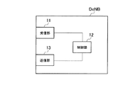
図2に示すように、無線基地局DeNBは、受信部11と、制御部12と、送信部13とを具備している。
As illustrated in FIG. 2, the radio base station DeNB includes a
受信部11は、リレーノードRNによって送信された信号を受信するように構成されている。
The
例えば、受信部11は、リレーノードRNから、「RRC UE Capability Information」を介して、「Half duplex inband Relay Node(Type 1 relay)」、「Full duplex inband Relay Node(Type 1b relay)」、「Outband Relay Node(Type 1a relay)」のどれかであることの通知を受信するように構成されている(例えば、3GPP TR36.814参照)。
For example, the
制御部12は、受信部11によって「Half duplex inband Relay Nodeであることの通知が受信された場合、UnサブフレームにおけるR-PDCCH(Relay-Physical Downlink Control Channel)及びR-PDSCH(Relay-Physical Downlink Shared Channel)の送信タイミング(例えば、送信開始シンボル)や、1つのUnサブフレーム内で受信可能なOFDMシンボル数や、UnサブフレームにおけるリレーノードRN宛てのDM-RS(Demodulation Reference Signal)の配置パターン等を決定するように構成されている。
When the
送信部13は、リレーノードRNに対して信号を送信するように構成されている。具体的には、送信部13は、Unサブフレーム内でスケジューリングされた第1サブフレームで第1下り信号を送信するように構成されている。
The
また、送信部13は、「RRC Conncetion Reconfiguration」によって、リレーノードRNに対して、制御部12によって決定されたUnサブフレームにおけるR-PDCCH及びR-PDSCHの送信タイミングや、1つのUnサブフレーム内で受信可能なOFDMシンボル数や、UnサブフレームにおけるリレーノードRN宛てのDM-RSの配置パターン等を送信するように構成されている。
Also, the
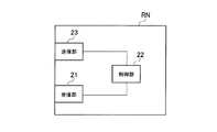
図3に示すように、リレーノードRNは、受信部21と、制御部22と、送信部23とを具備している。
As illustrated in FIG. 3, the relay node RN includes a
受信部21は、無線基地局DeNBや移動局UEによって送信された信号を受信するように構成されている。
The receiving
例えば、受信部21は、「RRC Conncetion Reconfiguration」を介して、UnサブフレームにおけるR-PDCCH及びR-PDSCHの送信タイミングや、1つのUnサブフレーム内で受信可能なOFDMシンボル数や、UnサブフレームにおけるリレーノードRN宛てのDM-RSの配置パターン等を受信するように構成されている。
For example, the
制御部22は、受信部21によって受信されたUnサブフレームにおけるR-PDCCH及びR-PDSCHの送信タイミングや、1つのUnサブフレーム内で受信可能なOFDMシンボル数や、UnサブフレームにおけるリレーノードRN宛てのDM-RSの配置パターン等に基づいて、リレーノードRNにおける通信を制御するように構成されている。
The
送信部23は、無線基地局DeNBや移動局UEに対して、信号を送信するように構成されている。具体的には、送信部23は、Uuサブフレーム内でスケジューリングされた第2サブフレームで第2下り信号を送信するように構成されている。
The
例えば、送信部23は、無線基地局DeNBに対して、「RRC UE Capability Information」によって、「Half duplex inband Relay Node(Type 1 relay)」、「Full duplex inband Relay Node(Type 1b relay)」、「Outband Relay Node(Type 1a relay)」のどれかであることの通知を送信するように構成されている(例えば、3GPP TR36.814参照)。
For example, the
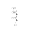
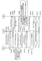
以下、図4及び図5を参照して、本実施形態に係る移動通信システムにおいて、無線基地局DeNBとリレーノードRNとの間でRRCコネクションを設定する際の動作について説明する。 Hereinafter, with reference to FIG.4 and FIG.5, the operation | movement at the time of setting an RRC connection between the radio base station DeNB and the relay node RN in the mobile communication system which concerns on this embodiment is demonstrated.
図4に示すように、ステップS1001において、リレーノードRNは、起動時に、無線基地局DeNBに対して、「RRC Connection Request」を送信する。 As illustrated in FIG. 4, in step S1001, the relay node RN transmits “RRC Connection Request” to the radio base station DeNB at the time of activation.
ステップS1002において、無線基地局DeNBは、「RRC Connection Request」内にリレーノードRNであることを示すフラグが設定されている場合、かかる「RRC Connection Request」がリレーノードRNから送信されたものであると判定し、リレーノードRNに対して、「RRC Connection Setup」を送信する。 In step S1002, if the flag indicating that the radio base station DeNB is a relay node RN is set in the "RRC Connection Request", the "RRC Connection Request" is transmitted from the relay node RN. And “RRC Connection Setup” is transmitted to the relay node RN.
ステップS1003において、リレーノードRNは、無線基地局DeNBに対して、「Attach Request」を含む「RRC Connection Setup Complete」を送信する。 In Step S1003, the relay node RN transmits “RRC Connection Setup Complete” including “Attach Request” to the radio base station DeNB.
ステップS1004において、無線基地局DeNBは、移動管理ノードMMEに対して、「Attach Request」を含む「Initial UE Message」を送信する。 In step S1004, the radio base station DeNB transmits “Initial UE Message” including “Attach Request” to the mobility management node MME.
ステップS1005において、リレーノードRNと移動管理ノードMMEとの間で「Authentication/Security処理」が完了した後、ステップS1006において、移動管理ノードMMEは、無線基地局DeNBに対して、「Attach Accept」を含む「Initial Context Setup Request」を送信する。 In step S1005, after the “Authentication / Security process” is completed between the relay node RN and the mobility management node MME, in step S1006, the mobility management node MME transmits “Attach Accept” to the radio base station DeNB. Including “Initial Context Setup Request” is transmitted.
移動管理ノードMMEは、加入者情報管理ノードHSS(Home Subscriber Server)から「Attach Request」を送信したノードがリレーノードRNであることを通知された場合、リレーノードRNであることを識別する情報を含む「Initial Context Setup Request」を送信する。 When the mobile management node MME is notified from the subscriber information management node HSS (Home Subscriber Server) that the node that has transmitted “Attach Request” is the relay node RN, the mobile management node MME receives information identifying the relay node RN. Including “Initial Context Setup Request” is transmitted.
ステップS1007において、無線基地局DeNBは、リレーノードRNに対して、「RRC UE Capability Enquiry」を送信する。 In step S1007, the radio base station DeNB transmits “RRC UE Capability Enquiry” to the relay node RN.
ステップS1008において、リレーノードRNは、無線基地局DeNBに対して、「RRC UE Capability Information」を送信する。 In Step S1008, the relay node RN transmits “RRC UE Capability Information” to the radio base station DeNB.
例えば、リレーノードRNは、図5に示すように、「RRC UE Capability Information」内の情報要素「UE-EUTRA-Capability」によって、無線基地局DeNBに対して、「Half duplex inband Relay Node」であることの通知を送信する。 For example, as illustrated in FIG. 5, the relay node RN is a “Half duplex inband Relay Node” for the radio base station DeNB by the information element “UE-EUTRA-Capability” in the “RRC UE Capability Information”. Send a notification of that.
ステップS1009において、無線基地局DeNBは、移動管理ノードMMEに対して、「RN(UE) Capability Info Indication」を送信する。 In step S1009, the radio base station DeNB transmits “RN (UE) Capability Info Indication” to the mobility management node MME.
無線基地局DeNBは、リレーノードRNに対して、ステップS1010において、「Security Mode Command」を送信し、ステップS1011において、「Attach Accept」を含む「RRC Connection Reconfiguration」を送信する。 The radio base station DeNB transmits “Security Mode Command” to the relay node RN in Step S1010, and transmits “RRC Connection Reconfiguration” including “Attach Accept” in Step S1011.
ここで、無線基地局DeNBは、リレーノードRNに対して、「RRC Connection Reconfiguration」によって、Unサブフレームの設定情報やUnサブフレームにおけるR-PDCCH及びR−PDSCHの送信タイミングや、1つのUnサブフレーム内で受信可能なOFDMシンボル数や、UnサブフレームにおけるリレーノードRN宛てのDM-RSの配置パターン等を送信することができる。 Here, the radio base station DeNB sends the Un subframe setting information, the transmission timing of the R-PDCCH and the R-PDSCH in the Un subframe, and one Un subframe to the relay node RN by “RRC Connection Reconfiguration”. The number of OFDM symbols that can be received in the frame, the arrangement pattern of DM-RSs addressed to the relay node RN in the Un subframe, etc. can be transmitted.
リレーノードRNは、無線基地局DeNBに対して、ステップS1012において、「Security Mode Complete」を送信し、ステップS1013において、「RRC Connection Reconfiguration Complete」を送信する。 In step S1012, the relay node RN transmits “Security Mode Complete” to the radio base station DeNB, and in step S1013, transmits “RRC Connection Reconfiguration Complete”.
ステップS1014において、無線基地局DeNBは、コアノードCNに対して、「Initial Context Setup Response」を送信する。 In step S1014, the radio base station DeNB transmits “Initial Context Setup Response” to the core node CN.
ステップS1015において、リレーノードRNは、Unサブフレーム上での下り信号の受信処理を開始する。 In step S1015, the relay node RN starts downlink signal reception processing on the Un subframe.
ステップS1015において、リレーノードRNは、移動管理ノードMMEに対して、「Attach Complete」を送信する。 In step S1015, the relay node RN transmits “Attach Complete” to the mobility management node MME.
ステップS1016において、リレーノードRNは、移動管理ノードMMEを介して、O&M(Operation & Maintenance)サーバから「Node Conifiguration」をダウンロードし、ステップS1017において、リレーノードRNと移動管理ノードMMEとの間で、S1/X2インターフェイスが確立される。 In step S1016, the relay node RN downloads “Node Configuration” from the O & M (Operation & Maintenance) server via the mobility management node MME, and in step S1017, between the relay node RN and the mobility management node MME. An S1 / X2 interface is established.
本実施形態に係る移動通信システムによれば、リレーノードRNは、無線基地局DeNBから受信したUnサブフレームにおけるR-PDCCH及びR-PDSCHの送信タイミングや、1つのUnサブフレーム内で受信可能なOFDMシンボル数や、UnサブフレームにおけるリレーノードRN宛てのDM-RSの配置パターン等に基づいて、リレーノードRNにおける通信を制御することができるので、適切に、Unサブフレームにおける送受信処理及びUuサブフレームにおける送受信処理が同時に行われることから引き起こされるリレーノード自身の受信回路への干渉を低減することができる。 According to the mobile communication system according to the present embodiment, the relay node RN can receive the transmission timing of the R-PDCCH and the R-PDSCH in the Un subframe received from the radio base station DeNB or within one Un subframe. Since communication in the relay node RN can be controlled based on the number of OFDM symbols, the arrangement pattern of the DM-RS addressed to the relay node RN in the Un subframe, etc., transmission / reception processing and Uu sub in the Un subframe are appropriately performed. Interference with the receiving circuit of the relay node itself caused by simultaneous transmission / reception processing in the frame can be reduced.
(本発明の第2の実施形態に係る移動通信システム)
図6を参照して、本発明の第2の実施形態に係る移動通信システムについて、上述の第1の実施形態に係る移動通信システムとの相違点に着目して説明する。
(Mobile communication system according to the second embodiment of the present invention)
With reference to FIG. 6, the mobile communication system according to the second embodiment of the present invention will be described by focusing on the differences from the mobile communication system according to the first embodiment described above.
以下、図6を参照して、本実施形態に係る移動通信システムにおいて、無線基地局DeNBとリレーノードRNとの間でRRCコネクションを設定する際の動作について説明する。 Hereinafter, with reference to FIG. 6, in the mobile communication system according to the present embodiment, an operation when setting an RRC connection between the radio base station DeNB and the relay node RN will be described.
図6に示すように、ステップS2001乃至S2020の動作は、図4に示すステップS1001乃至S1020の動作と同一である。 As shown in FIG. 6, the operations in steps S2001 to S2020 are the same as the operations in steps S1001 to S1020 shown in FIG.
ステップS2011において、「Attach Accept」を含む「RRC Connection Reconfiguration」を送信する。 In step S2011, “RRC Connection Reconfiguration” including “Attach Accept” is transmitted.
ここで、上述の第1の実施形態に係る移動通信システムの場合と違って、無線基地局DeNBは、リレーノードRNに対して、「RRC Connection Reconfiguration」によって、Unサブフレームの設定情報やUnサブフレームにおけるR-PDCCH及びR-PDSCHの送信タイミングや、1つのUnサブフレーム内で受信可能なOFDMシンボル数や、UnサブフレームにおけるリレーノードRN宛てのDM-RSの配置パターン等を送信しない。 Here, unlike the case of the mobile communication system according to the first embodiment described above, the radio base station DeNB, for the relay node RN, uses “RRC Connection Reconfiguration” to set configuration information and Un subframe of the Un subframe. The transmission timing of the R-PDCCH and R-PDSCH in the frame, the number of OFDM symbols that can be received in one Un subframe, the arrangement pattern of the DM-RS addressed to the relay node RN in the Un subframe, and the like are not transmitted.
リレーノードRNは、無線基地局DeNBに対して、ステップS2012において、「Security Mode Complete」を送信し、ステップS2013において、「RRC Connection Reconfiguration Complete」を送信する。 The relay node RN transmits “Security Mode Complete” to the radio base station DeNB in step S2012, and transmits “RRC Connection Reconfiguration Complete” in step S2013.
ステップS2014において、無線基地局DeNBは、コアノードCNに対して、「Initial Context Setup Response」を送信する。 In step S2014, the radio base station DeNB transmits an “Initial Context Setup Response” to the core node CN.
ステップS2015において、リレーノードRNは、移動管理ノードMMEに対して、「Attach Complete」を送信する。 In step S2015, the relay node RN transmits “Attach Complete” to the mobility management node MME.
ステップS2016において、リレーノードRNは、移動管理ノードMMEを介して、O&Mサーバから「Node Conifiguration」をダウンロードし、ステップS2017において、リレーノードRNと移動管理ノードMMEとの間で、S1/X2インターフェイスが確立される。 In step S2016, the relay node RN downloads “Node Configuration” from the O & M server via the mobility management node MME, and in step S2017, the S1 / X2 interface is established between the relay node RN and the mobility management node MME. Established.
ステップS2018において、無線基地局DeNBは、リレーノードRNに対して、新規のRRCメッセージである「RRC Un Subframe Configuration」或いは「RRC Connection Reconfiguration」によって、Unサブフレームの設定情報やUnサブフレームにおけるR-PDCCH及びR-PDSCHの送信タイミングや、1つのUnサブフレーム内で受信可能なOFDMシンボル数や、UnサブフレームにおけるリレーノードRN宛てのDM-RSの配置パターン等を送信する。 In step S2018, the radio base station DeNB sends the new RRC message “RRC Un Subframe Configuration” or “RRC Connection Reconfiguration” to the relay node RN, the setting information of the Un subframe and the R− in the Un subframe. The transmission timing of the PDCCH and R-PDSCH, the number of OFDM symbols that can be received in one Un subframe, the arrangement pattern of DM-RSs addressed to the relay node RN in the Un subframe, and the like are transmitted.
ステップS2019において、リレーノードRNは、無線基地局DeNBに対して、新規のRRCメッセージである「RRC Un Subframe Configuration Complete」或いは「RRC Connection Reconfiguration Complete」を送信する。 In step S2019, the relay node RN transmits “RRC Un Subframe Configuration Complete” or “RRC Connection Reconfiguration Complete”, which is a new RRC message, to the radio base station DeNB.
ステップS2020において、リレーノードRNは、Unサブフレーム上での下り信号の受信処理を開始する。 In step S2020, the relay node RN starts downlink signal reception processing on the Un subframe.
以上に述べた本実施形態の特徴は、以下のように表現されていてもよい。 The characteristics of the present embodiment described above may be expressed as follows.
本実施形態の第1の特徴は、移動通信方法であって、無線基地局DeNBが、リレーノードRNに対して、第1サブフレームで第1下り信号を送信する工程と、リレーノードRNが、移動局UEに対して、第2サブフレームで第2下り信号を送信する工程と、リレーノードRNが、無線基地局DeNBに対して、「Half duplex inband Relay Node」であること(第1サブフレームと第2サブフレームとが時間方向で重複しないようにすべきであること)を通知する工程と、無線基地局DeNBが、かかる通知に応じて、リレーノードRNに対して、Unサブフレーム(無線基地局DeNBとリレーノードRNとの間のサブフレーム)におけるR-PDCCH(リレーノードRN宛ての物理下りリンク制御チャネル)及びR-PDSCH(リレーノードRN宛ての物理下りリンク共有チャネル)の送信タイミングを送信する工程とを有することを要旨とする。 The first feature of the present embodiment is a mobile communication method, in which the radio base station DeNB transmits a first downlink signal in a first subframe to the relay node RN, and the relay node RN includes: The step of transmitting the second downlink signal in the second subframe to the mobile station UE, and the relay node RN being a “Half duplex inband Relay Node” to the radio base station DeNB (first subframe) And the radio base station DeNB in response to the notification, the Un subframe (radio) and the second subframe are notified to the relay node RN in response to the notification. R-PDCCH (physical downlink control channel addressed to relay node RN) in base station DeNB and relay node RN) And summarized in that and a step of transmitting the transmission timing of the R-PDSCH (physical downlink shared channel of the relay node RN addressed).
本実施形態の第1の特徴において、R-PDCCHは、上りリンクにおけるHARQ-ACKを送信するチャネルであってもよい。 In the first feature of the present embodiment, the R-PDCCH may be a channel that transmits HARQ-ACK in the uplink.
本実施形態の第2の特徴は、移動通信方法であって、無線基地局DeNBが、リレーノードRNに対して、第1サブフレームで第1下り信号を送信する工程と、リレーノードRNが、移動局UEに対して、第2サブフレームで第2下り信号を送信する工程と、リレーノードRNが、無線基地局DeNBに対して、「Half duplex inband Relay Node」であることを通知する工程と、無線基地局DeNBが、かかる通知に応じて、リレーノードRNに対して、1つのUnサブフレーム内で受信可能なOFDMシンボル数を送信する工程とを有することを要旨とする。 A second feature of the present embodiment is a mobile communication method, in which the radio base station DeNB transmits a first downlink signal in a first subframe to the relay node RN, and the relay node RN includes: A step of transmitting the second downlink signal in the second subframe to the mobile station UE, and a step of notifying the radio base station DeNB that the relay node RN is a “Half duplex inband Relay Node” The wireless base station DeNB includes a step of transmitting the number of OFDM symbols that can be received within one Un subframe to the relay node RN in response to the notification.
本実施形態の第3の特徴は、移動通信方法であって、無線基地局DeNBが、リレーノードRNに対して、第1サブフレームで第1下り信号を送信する工程と、リレーノードRNが、移動局UEに対して、第2サブフレームで第2下り信号を送信する工程と、リレーノードRNが、無線基地局DeNBに対して、「Half duplex inband Relay Node」であることを通知する工程と、無線基地局DeNBが、かかる通知に応じて、リレーノードRNに対して、UnサブフレームにおけるリレーノードRN宛てのDM-RS(復号用参照信号)の配置パターンを送信する工程とを有することを要旨とする。 A third feature of the present embodiment is a mobile communication method, in which the radio base station DeNB transmits a first downlink signal in a first subframe to the relay node RN, and the relay node RN includes: A step of transmitting the second downlink signal in the second subframe to the mobile station UE, and a step of notifying the radio base station DeNB that the relay node RN is a “Half duplex inband Relay Node” The radio base station DeNB, in response to the notification, has a step of transmitting a DM-RS (decoding reference signal) arrangement pattern addressed to the relay node RN in the Un subframe to the relay node RN. The gist.
本実施形態の第4の特徴は、リレーノードRNが、移動局UEに対して、第2サブフレームで第2下り信号を送信するように構成されている移動通信システムで用いられる無線基地局DeNBであって、リレーノードRNに対して、第1サブフレームで第1下り信号を送信するように構成されている送信部13を具備しており、リレーノードRNから、「Half duplex inband Relay Node」であることの通知を受信した場合、送信部13は、リレーノードRNに対して、UnサブフレームにおけるR-PDCCH及びR-PDSCHの送信タイミングを送信するように構成されていることを要旨とする。
A fourth feature of the present embodiment is that a radio base station DeNB used in a mobile communication system in which the relay node RN is configured to transmit a second downlink signal in the second subframe to the mobile station UE. The relay unit RN includes a
本実施形態の第4の特徴において、R-PDCCHは、上りリンクにおけるHARQ-ACKを送信するチャネルであってもよい。 In the fourth feature of the present embodiment, the R-PDCCH may be a channel for transmitting HARQ-ACK in the uplink.
本実施形態の第5の特徴は、リレーノードRNが、移動局UEに対して、第2サブフレームで第2下り信号を送信するように構成されている移動通信システムで用いられる無線基地局DeNBであって、リレーノードRNに対して、第1サブフレームで第1下り信号を送信するように構成されている送信部13を具備しており、リレーノードRNから、「Half duplex inband Relay Node」であることの通知を受信した場合、送信部13は、リレーノードRNに対して、1つのUnサブフレーム内で受信可能なOFDMシンボル数を送信するように構成されていることを要旨とする。
A fifth feature of the present embodiment is that a radio base station DeNB used in a mobile communication system in which the relay node RN is configured to transmit a second downlink signal in a second subframe to the mobile station UE. The relay unit RN includes a
本実施形態の第6の特徴は、リレーノードRNが、移動局UEに対して、第2サブフレームで第2下り信号を送信するように構成されている移動通信システムで用いられる無線基地局DeNBであって、リレーノードRNに対して、第1サブフレームで第1下り信号を送信するように構成されている送信部13を具備しており、リレーノードRNから、「Half duplex inband Relay Node」であることの通知を受信した場合、送信部13は、リレーノードRNに対して、UnサブフレームにおけるリレーノードRN宛てのDM-RSの配置パターンを送信するように構成されていることを要旨とする。
A sixth feature of the present embodiment is that a radio base station DeNB used in a mobile communication system in which the relay node RN is configured to transmit a second downlink signal in the second subframe to the mobile station UE. The relay unit RN includes a
なお、上述の移動管理ノードMMEや無線基地局DeNBやリレーノードRNや移動局UEの動作は、ハードウェアによって実施されてもよいし、プロセッサによって実行されるソフトウェアモジュールによって実施されてもよいし、両者の組み合わせによって実施されてもよい。 The operations of the mobility management node MME, the radio base station DeNB, the relay node RN, and the mobile station UE described above may be implemented by hardware or may be implemented by a software module executed by a processor, You may implement by the combination of both.
ソフトウェアモジュールは、RAM(Random Access Memory)や、フラッシュメモリや、ROM(Read Only Memory)や、EPROM(Erasable Programmable ROM)や、EEPROM(Electronically Erasable and Programmable ROM)や、レジスタや、ハードディスクや、リムーバブルディスクや、CD-ROMといった任意形式の記憶媒体内に設けられていてもよい。 The software module includes a RAM (Random Access Memory), a flash memory, a ROM (Read Only Memory), an EPROM (Erasable Programmable ROM), an EEPROM (Electronically Erasable and Programmable ROM, a Hard Disk, a Registered ROM, a Hard Disk Alternatively, it may be provided in a storage medium of an arbitrary format such as a CD-ROM.
かかる記憶媒体は、プロセッサが当該記憶媒体に情報を読み書きできるように、当該プロセッサに接続されている。また、かかる記憶媒体は、プロセッサに集積されていてもよい。また、かかる記憶媒体及びプロセッサは、ASIC内に設けられていてもよい。かかるASICは、移動管理ノードMMEや無線基地局DeNBやリレーノードRNや移動局UE内に設けられていてもよい。また、かかる記憶媒体及びプロセッサは、ディスクリートコンポーネントとして移動管理ノードMMEや無線基地局DeNBやリレーノードRNや移動局UE内に設けられていてもよい。 Such a storage medium is connected to the processor so that the processor can read and write information from and to the storage medium. Further, such a storage medium may be integrated in the processor. Such a storage medium and processor may be provided in the ASIC. Such an ASIC may be provided in the mobility management node MME, the radio base station DeNB, the relay node RN, or the mobile station UE. Further, the storage medium and the processor may be provided as a discrete component in the mobility management node MME, the radio base station DeNB, the relay node RN, or the mobile station UE.
以上、上述の実施形態を用いて本発明について詳細に説明したが、当業者にとっては、本発明が本明細書中に説明した実施形態に限定されるものではないということは明らかである。本発明は、特許請求の範囲の記載により定まる本発明の趣旨及び範囲を逸脱することなく修正及び変更態様として実施することができる。従って、本明細書の記載は、例示説明を目的とするものであり、本発明に対して何ら制限的な意味を有するものではない。 Although the present invention has been described in detail using the above-described embodiments, it is obvious to those skilled in the art that the present invention is not limited to the embodiments described in this specification. The present invention can be implemented as modified and changed modes without departing from the spirit and scope of the present invention defined by the description of the scope of claims. Therefore, the description of the present specification is for illustrative purposes and does not have any limiting meaning to the present invention.
MME…移動管理ノード
UE…移動局
DeNB…無線基地局
RN…リレーノード
11、21…受信部
12、22…制御部
13、23…送信部
MME ... mobility management node UE ... mobile station DeNB ... radio base station RN ...
Claims (6)
前記リレーノードが、移動局に対して、第2サブフレームで第2下り信号を送信する工程と、
前記リレーノードが、前記無線基地局に対して、前記第1サブフレームと前記第2サブフレームとが時間方向で重複しないようにすべきであることを通知する工程と、
前記無線基地局が、前記通知に応じて、前記リレーノードのアタッチ処理が完了した後に、該リレーノードに対して、該無線基地局と該リレーノードとの間のサブフレームにおける該リレーノード宛ての物理下りリンク制御チャネル及び物理下りリンク共有チャネルの送信タイミングを送信する工程とを有することを特徴とする移動通信方法。 A step in which a radio base station transmits a first downlink signal in a first subframe to a relay node;
The relay node transmits a second downlink signal in a second subframe to the mobile station;
The relay node notifying the radio base station that the first subframe and the second subframe should not overlap in the time direction;
In response to the notification, the radio base station is directed to the relay node in the subframe between the radio base station and the relay node after the relay node attach process is completed . Transmitting a transmission timing of a physical downlink control channel and a physical downlink shared channel.
前記リレーノードが、移動局に対して、第2サブフレームで第2下り信号を送信する工程と、
前記リレーノードが、前記無線基地局に対して、前記第1サブフレームと前記第2サブフレームとが時間方向で重複しないようにすべきであることを通知する工程と、
前記無線基地局が、前記通知に応じて、前記リレーノードのアタッチ処理が完了した後に、該リレーノードに対して、該無線基地局と該リレーノードとの間のサブフレームにおける該リレーノード宛ての復号用参照信号の配置パターンを送信する工程とを有することを特徴とする移動通信方法。 A step in which a radio base station transmits a first downlink signal in a first subframe to a relay node;
The relay node transmits a second downlink signal in a second subframe to the mobile station;
The relay node notifying the radio base station that the first subframe and the second subframe should not overlap in the time direction;
In response to the notification, the radio base station is directed to the relay node in the subframe between the radio base station and the relay node after the relay node attach process is completed . And a step of transmitting an arrangement pattern of decoding reference signals.
前記リレーノードに対して、第1サブフレームで第1下り信号を送信するように構成されている送信部を具備しており、
前記リレーノードから、前記第1サブフレームと前記第2サブフレームとが時間方向で重複しないようにすべきであることの通知を受信した場合、前記送信部は、該リレーノードのアタッチ処理が完了した後に、該リレーノードに対して、前記無線基地局と該リレーノードとの間のサブフレームにおける該リレーノード宛ての物理下りリンク制御チャネル及び物理下りリンク共有チャネルの送信タイミングを送信するように構成されていることを特徴とする無線基地局。 A relay node is a radio base station used in a mobile communication system configured to transmit a second downlink signal in a second subframe to a mobile station,
A relay unit configured to transmit a first downlink signal in a first subframe to the relay node;
When receiving a notification from the relay node that the first subframe and the second subframe should not overlap in the time direction, the transmitter completes the process of attaching the relay node After that, the transmission timing of the physical downlink control channel and the physical downlink shared channel addressed to the relay node in a subframe between the radio base station and the relay node is transmitted to the relay node A radio base station characterized in that
前記リレーノードに対して、第1サブフレームで第1下り信号を送信するように構成されている送信部を具備しており、
前記リレーノードから、前記第1サブフレームと前記第2サブフレームとが時間方向で重複しないようにすべきであることの通知を受信した場合、前記送信部は、該リレーノードのアタッチ処理が完了した後に、該リレーノードに対して、前記無線基地局と該リレーノードとの間のサブフレームにおける該リレーノード宛ての復号用参照信号の配置パターンを送信するように構成されていることを特徴とする無線基地局。 A relay node is a radio base station used in a mobile communication system configured to transmit a second downlink signal in a second subframe to a mobile station,
A relay unit configured to transmit a first downlink signal in a first subframe to the relay node;
When receiving a notification from the relay node that the first subframe and the second subframe should not overlap in the time direction, the transmitter completes the process of attaching the relay node After that, it is configured to transmit the arrangement pattern of the reference signal for decoding addressed to the relay node in the subframe between the radio base station and the relay node to the relay node. Wireless base station.
Priority Applications (10)
| Application Number | Priority Date | Filing Date | Title |
|---|---|---|---|
| JP2010141108A JP5073786B2 (en) | 2010-06-21 | 2010-06-21 | Mobile communication method and radio base station |
| US13/805,743 US9832768B2 (en) | 2010-06-21 | 2011-06-20 | Mobile communication method and radio base station |
| PCT/JP2011/064076 WO2011162211A1 (en) | 2010-06-21 | 2011-06-20 | Mobile communication method and wireless base station |
| BR112012032735A BR112012032735A2 (en) | 2010-06-21 | 2011-06-20 | Mobile communication method and radio base station. |
| CN2011800307866A CN102948189A (en) | 2010-06-21 | 2011-06-20 | Mobile communication method and wireless base station |
| MX2012015262A MX2012015262A (en) | 2010-06-21 | 2011-06-20 | Mobile communication method and wireless base station. |
| KR1020137000133A KR101298726B1 (en) | 2010-06-21 | 2011-06-20 | Mobile communication method and wireless base sation |
| EP11798095.3A EP2584811B1 (en) | 2010-06-21 | 2011-06-20 | Mobile communication method and wireless base station |
| RU2012157385/07A RU2546170C2 (en) | 2010-06-21 | 2011-06-20 | Mobile communication method and radio base station |
| IL223740A IL223740A (en) | 2010-06-21 | 2012-12-19 | Mobile communication method and wireless base station |
Applications Claiming Priority (1)
| Application Number | Priority Date | Filing Date | Title |
|---|---|---|---|
| JP2010141108A JP5073786B2 (en) | 2010-06-21 | 2010-06-21 | Mobile communication method and radio base station |
Publications (2)
| Publication Number | Publication Date |
|---|---|
| JP2012005092A JP2012005092A (en) | 2012-01-05 |
| JP5073786B2 true JP5073786B2 (en) | 2012-11-14 |
Family
ID=45371394
Family Applications (1)
| Application Number | Title | Priority Date | Filing Date |
|---|---|---|---|
| JP2010141108A Active JP5073786B2 (en) | 2010-06-21 | 2010-06-21 | Mobile communication method and radio base station |
Country Status (10)
| Country | Link |
|---|---|
| US (1) | US9832768B2 (en) |
| EP (1) | EP2584811B1 (en) |
| JP (1) | JP5073786B2 (en) |
| KR (1) | KR101298726B1 (en) |
| CN (1) | CN102948189A (en) |
| BR (1) | BR112012032735A2 (en) |
| IL (1) | IL223740A (en) |
| MX (1) | MX2012015262A (en) |
| RU (1) | RU2546170C2 (en) |
| WO (1) | WO2011162211A1 (en) |
Families Citing this family (12)
| Publication number | Priority date | Publication date | Assignee | Title |
|---|---|---|---|---|
| EP2564611B1 (en) | 2011-07-01 | 2015-02-18 | Ofinno Technologies, LLC | Synchronization signal and control messages in multicarrier OFDM |
| US8582527B2 (en) | 2011-07-01 | 2013-11-12 | Ofinno Technologies, Llc | Hybrid automatic repeat request in multicarrier systems |
| US8369280B2 (en) | 2011-07-01 | 2013-02-05 | Ofinno Techologies, LLC | Control channels in multicarrier OFDM transmission |
| US8427976B1 (en) | 2011-12-04 | 2013-04-23 | Ofinno Technology, LLC | Carrier information exchange between base stations |
| GB201201915D0 (en) * | 2012-02-03 | 2012-03-21 | Nec Corp | Mobile communications device and system |
| US9497756B2 (en) | 2012-03-25 | 2016-11-15 | Comcast Cable Communications, Llc | Base station radio resource management |
| US9949265B2 (en) | 2012-05-04 | 2018-04-17 | Comcast Cable Communications, Llc | Control channel in a wireless communication system |
| JP6035227B2 (en) * | 2013-10-31 | 2016-11-30 | 株式会社Nttドコモ | Mobile communication method |
| CN108430058B (en) * | 2017-02-13 | 2021-10-22 | 大唐移动通信设备有限公司 | LTE-based UE capability information reporting verification method and base station |
| CN110999453B (en) * | 2017-07-27 | 2023-10-13 | 株式会社Ntt都科摩 | User terminal and wireless communication method |
| CN108513729B (en) * | 2017-07-31 | 2021-06-08 | 深圳市大疆创新科技有限公司 | Out-of-step processing method, intermediate communication device and communication system |
| US20240147460A1 (en) * | 2021-05-27 | 2024-05-02 | Qualcomm Incorporated | Resource allocation for pdcch with multi-relay based communication |
Family Cites Families (20)
| Publication number | Priority date | Publication date | Assignee | Title |
|---|---|---|---|---|
| CA2199098C (en) * | 1996-03-06 | 2000-08-22 | Takehiro Nakamura | Cell selection scheme in cdma mobile communication system using spread codes and spread code phases |
| KR100304924B1 (en) * | 1997-12-30 | 2001-11-22 | 서평원 | Inter-frequency handoff control method in cdma cellular system |
| KR100975743B1 (en) * | 2005-07-14 | 2010-08-12 | 삼성전자주식회사 | Method and apparatus for relaying signal in wireless communication system |
| US8638771B2 (en) * | 2005-08-12 | 2014-01-28 | Qualcomm Incorporated | Transmission structure supporting multi-user scheduling and MIMO transmission |
| CN101305522A (en) * | 2006-04-28 | 2008-11-12 | 三菱电机研究实验室 | Method and system for processing reference signal using transmission time interval packet |
| US20080165881A1 (en) * | 2007-01-08 | 2008-07-10 | Zhifeng Tao | Method for Accessing Channels in OFDMA Mobile Multihop Relay Networks |
| US8953467B2 (en) * | 2008-09-08 | 2015-02-10 | Nokia Corporation | Adaptive transmission modes for transparent relay |
| US8971241B2 (en) * | 2008-09-30 | 2015-03-03 | Qualcolmm Incorporated | Techniques for supporting relay operation in wireless communication systems |
| KR101357923B1 (en) * | 2008-10-23 | 2014-02-03 | 에릭슨 엘지 주식회사 | Apparatus and method for cancellating self-interference and relay system for the same |
| CN102217352B (en) * | 2008-11-18 | 2016-04-20 | 诺基亚技术有限公司 | Carry out relaying in a communications system |
| KR101577455B1 (en) * | 2008-12-03 | 2015-12-15 | 엘지전자 주식회사 | Method of relaying data |
| US8514768B2 (en) * | 2008-12-11 | 2013-08-20 | Lg Electronics Inc. | Method and apparatus for transmitting reference signal performed by relay station in wireless communication system |
| US8537724B2 (en) * | 2009-03-17 | 2013-09-17 | Motorola Mobility Llc | Relay operation in a wireless communication system |
| WO2010137318A1 (en) * | 2009-05-26 | 2010-12-02 | 京セラ株式会社 | Wireless communication terminal, base station, wireless communication method and wireless communication system |
| JP2010278887A (en) * | 2009-05-29 | 2010-12-09 | Panasonic Corp | Base station device, terminal device, radio communication system and transmission method |
| US8848623B2 (en) * | 2009-08-21 | 2014-09-30 | Blackberry Limited | System and method for channel timing offset |
| US8761074B2 (en) * | 2009-08-27 | 2014-06-24 | Futurewei Technologies, Inc. | Relay backhaul in wireless communication |
| US9014079B2 (en) * | 2009-10-29 | 2015-04-21 | Telefonaktiebolaget L M Ericsson (Publ) | Intra-subframe time multiplexing |
| CN102118757B (en) * | 2009-12-31 | 2013-11-06 | 中兴通讯股份有限公司 | Wireless relay device and method for communicating wireless relay device with base station and terminal |
| US8787214B2 (en) * | 2010-05-25 | 2014-07-22 | Telefonaktiebolaget L M Ericcson (Publ) | Method and arrangement in a wireless communication network |
-
2010
- 2010-06-21 JP JP2010141108A patent/JP5073786B2/en active Active
-
2011
- 2011-06-20 RU RU2012157385/07A patent/RU2546170C2/en not_active IP Right Cessation
- 2011-06-20 EP EP11798095.3A patent/EP2584811B1/en active Active
- 2011-06-20 BR BR112012032735A patent/BR112012032735A2/en not_active Application Discontinuation
- 2011-06-20 US US13/805,743 patent/US9832768B2/en active Active
- 2011-06-20 KR KR1020137000133A patent/KR101298726B1/en active IP Right Grant
- 2011-06-20 CN CN2011800307866A patent/CN102948189A/en active Pending
- 2011-06-20 WO PCT/JP2011/064076 patent/WO2011162211A1/en active Application Filing
- 2011-06-20 MX MX2012015262A patent/MX2012015262A/en active IP Right Grant
-
2012
- 2012-12-19 IL IL223740A patent/IL223740A/en active IP Right Grant
Also Published As
| Publication number | Publication date |
|---|---|
| MX2012015262A (en) | 2013-02-12 |
| EP2584811A1 (en) | 2013-04-24 |
| CN102948189A (en) | 2013-02-27 |
| RU2012157385A (en) | 2014-07-27 |
| US20130176936A1 (en) | 2013-07-11 |
| KR101298726B1 (en) | 2013-08-22 |
| JP2012005092A (en) | 2012-01-05 |
| IL223740A (en) | 2016-09-29 |
| US9832768B2 (en) | 2017-11-28 |
| KR20130018978A (en) | 2013-02-25 |
| EP2584811A4 (en) | 2014-03-05 |
| EP2584811B1 (en) | 2016-04-13 |
| BR112012032735A2 (en) | 2016-11-08 |
| WO2011162211A1 (en) | 2011-12-29 |
| RU2546170C2 (en) | 2015-04-10 |
Similar Documents
| Publication | Publication Date | Title |
|---|---|---|
| JP5073786B2 (en) | Mobile communication method and radio base station | |
| JP5187909B2 (en) | Mobile communication method and relay node | |
| WO2011111111A1 (en) | Communication section setting method, relay station and mobile communication system | |
| WO2012023514A1 (en) | Mobile communication method, relay node and wireless base station | |
| JP4660609B2 (en) | Mobile communication method, radio base station, and relay node | |
| WO2012165411A1 (en) | Mobile communication method, relay node, and wireless base station | |
| JP4814383B2 (en) | Mobile communication method and relay node | |
| JP4769898B2 (en) | Mobile communication system and radio base station | |
| JP4749480B2 (en) | Mobile communication method, radio base station, and relay node | |
| WO2010150777A1 (en) | Mobile communication method, radio base station, and relay node | |
| JP2011066943A (en) | Mobile communication method, radio base station, and relay node | |
| JP2011004375A (en) | Mobile communication method, radio base station and relay node | |
| KR20170113758A (en) | Method and apparatus for scheduling in mobile communication system | |
| JP2012217188A (en) | Mobile communication method and radio base station |
Legal Events
| Date | Code | Title | Description |
|---|---|---|---|
| A131 | Notification of reasons for refusal |
Free format text: JAPANESE INTERMEDIATE CODE: A131 Effective date: 20120117 |
|
| A521 | Request for written amendment filed |
Free format text: JAPANESE INTERMEDIATE CODE: A523 Effective date: 20120319 |
|
| TRDD | Decision of grant or rejection written | ||
| A01 | Written decision to grant a patent or to grant a registration (utility model) |
Free format text: JAPANESE INTERMEDIATE CODE: A01 Effective date: 20120724 |
|
| A01 | Written decision to grant a patent or to grant a registration (utility model) |
Free format text: JAPANESE INTERMEDIATE CODE: A01 |
|
| A61 | First payment of annual fees (during grant procedure) |
Free format text: JAPANESE INTERMEDIATE CODE: A61 Effective date: 20120822 |
|
| R150 | Certificate of patent or registration of utility model |
Ref document number: 5073786 Country of ref document: JP Free format text: JAPANESE INTERMEDIATE CODE: R150 Free format text: JAPANESE INTERMEDIATE CODE: R150 |
|
| FPAY | Renewal fee payment (event date is renewal date of database) |
Free format text: PAYMENT UNTIL: 20150831 Year of fee payment: 3 |
|
| R250 | Receipt of annual fees |
Free format text: JAPANESE INTERMEDIATE CODE: R250 |
|
| R250 | Receipt of annual fees |
Free format text: JAPANESE INTERMEDIATE CODE: R250 |
|
| R250 | Receipt of annual fees |
Free format text: JAPANESE INTERMEDIATE CODE: R250 |
|
| R250 | Receipt of annual fees |
Free format text: JAPANESE INTERMEDIATE CODE: R250 |
|
| R250 | Receipt of annual fees |
Free format text: JAPANESE INTERMEDIATE CODE: R250 |
|
| R250 | Receipt of annual fees |
Free format text: JAPANESE INTERMEDIATE CODE: R250 |
|
| R250 | Receipt of annual fees |
Free format text: JAPANESE INTERMEDIATE CODE: R250 |
|
| R250 | Receipt of annual fees |
Free format text: JAPANESE INTERMEDIATE CODE: R250 |
|
| R250 | Receipt of annual fees |
Free format text: JAPANESE INTERMEDIATE CODE: R250 |