JP5073052B2 - Error correction circuit and disk storage device - Google Patents
Error correction circuit and disk storage device Download PDFInfo
- Publication number
- JP5073052B2 JP5073052B2 JP2010506723A JP2010506723A JP5073052B2 JP 5073052 B2 JP5073052 B2 JP 5073052B2 JP 2010506723 A JP2010506723 A JP 2010506723A JP 2010506723 A JP2010506723 A JP 2010506723A JP 5073052 B2 JP5073052 B2 JP 5073052B2
- Authority
- JP
- Japan
- Prior art keywords
- error
- marker
- bit
- deletion
- data string
- Prior art date
- Legal status (The legal status is an assumption and is not a legal conclusion. Google has not performed a legal analysis and makes no representation as to the accuracy of the status listed.)
- Expired - Fee Related
Links
Images


Classifications
-
- G—PHYSICS
- G11—INFORMATION STORAGE
- G11B—INFORMATION STORAGE BASED ON RELATIVE MOVEMENT BETWEEN RECORD CARRIER AND TRANSDUCER
- G11B20/00—Signal processing not specific to the method of recording or reproducing; Circuits therefor
- G11B20/10—Digital recording or reproducing
- G11B20/18—Error detection or correction; Testing, e.g. of drop-outs
-
- B—PERFORMING OPERATIONS; TRANSPORTING
- B82—NANOTECHNOLOGY
- B82Y—SPECIFIC USES OR APPLICATIONS OF NANOSTRUCTURES; MEASUREMENT OR ANALYSIS OF NANOSTRUCTURES; MANUFACTURE OR TREATMENT OF NANOSTRUCTURES
- B82Y10/00—Nanotechnology for information processing, storage or transmission, e.g. quantum computing or single electron logic
-
- G—PHYSICS
- G11—INFORMATION STORAGE
- G11B—INFORMATION STORAGE BASED ON RELATIVE MOVEMENT BETWEEN RECORD CARRIER AND TRANSDUCER
- G11B5/00—Recording by magnetisation or demagnetisation of a record carrier; Reproducing by magnetic means; Record carriers therefor
- G11B5/74—Record carriers characterised by the form, e.g. sheet shaped to wrap around a drum
- G11B5/743—Patterned record carriers, wherein the magnetic recording layer is patterned into magnetic isolated data islands, e.g. discrete tracks
-
- G—PHYSICS
- G11—INFORMATION STORAGE
- G11B—INFORMATION STORAGE BASED ON RELATIVE MOVEMENT BETWEEN RECORD CARRIER AND TRANSDUCER
- G11B20/00—Signal processing not specific to the method of recording or reproducing; Circuits therefor
- G11B20/10—Digital recording or reproducing
- G11B2020/10851—Erasing data on the record carrier
-
- G—PHYSICS
- G11—INFORMATION STORAGE
- G11B—INFORMATION STORAGE BASED ON RELATIVE MOVEMENT BETWEEN RECORD CARRIER AND TRANSDUCER
- G11B20/00—Signal processing not specific to the method of recording or reproducing; Circuits therefor
- G11B20/10—Digital recording or reproducing
- G11B20/18—Error detection or correction; Testing, e.g. of drop-outs
- G11B20/1816—Testing
- G11B2020/1823—Testing wherein a flag is set when errors are detected or qualified
-
- G—PHYSICS
- G11—INFORMATION STORAGE
- G11B—INFORMATION STORAGE BASED ON RELATIVE MOVEMENT BETWEEN RECORD CARRIER AND TRANSDUCER
- G11B20/00—Signal processing not specific to the method of recording or reproducing; Circuits therefor
- G11B20/10—Digital recording or reproducing
- G11B20/18—Error detection or correction; Testing, e.g. of drop-outs
- G11B20/1833—Error detection or correction; Testing, e.g. of drop-outs by adding special lists or symbols to the coded information
- G11B2020/1843—Error detection or correction; Testing, e.g. of drop-outs by adding special lists or symbols to the coded information using a cyclic redundancy check [CRC]
-
- G—PHYSICS
- G11—INFORMATION STORAGE
- G11B—INFORMATION STORAGE BASED ON RELATIVE MOVEMENT BETWEEN RECORD CARRIER AND TRANSDUCER
- G11B2220/00—Record carriers by type
- G11B2220/20—Disc-shaped record carriers
- G11B2220/25—Disc-shaped record carriers characterised in that the disc is based on a specific recording technology
- G11B2220/2508—Magnetic discs
- G11B2220/2516—Hard disks
Landscapes
- Engineering & Computer Science (AREA)
- Chemical & Material Sciences (AREA)
- Nanotechnology (AREA)
- Signal Processing (AREA)
- Physics & Mathematics (AREA)
- Mathematical Physics (AREA)
- Theoretical Computer Science (AREA)
- Crystallography & Structural Chemistry (AREA)
- Signal Processing For Digital Recording And Reproducing (AREA)
- Error Detection And Correction (AREA)
Description
本発明は、記憶ディスクの読み出し信号の誤りを訂正する誤り訂正回路及びディスク記憶装置に関する。 The present invention relates to an error correction circuit for correcting an error in a read signal of a storage disk and a disk storage device.
磁気ディスク装置等のディスク記憶装置では、ディスク記憶媒体に、連続記録媒体を使用してきた。近年、記録密度向上のため、この連続記録媒体に代わり、媒体上に記憶ドットを作成した非連続媒体を用いる手法が提案されている。この手法は、ビットパターンドメディア(BPM)方式と呼ばれている。 In disk storage devices such as magnetic disk devices, continuous recording media have been used as disk storage media. In recent years, in order to improve the recording density, a method using a discontinuous medium in which memory dots are created on the medium has been proposed instead of the continuous recording medium. This method is called a bit patterned media (BPM) system.
この孤立した記憶ドットに、磁気ヘッドで記録を行うため、ライト同期方法が用いられている。図1は、ライト同期方法の説明図である。図1に示すように、ライト同期方式は、記録媒体上に形成された各記録ドットDの間隔に合わせて、ライトクロックWRCを補正し、ライトクロックWRCに同期して、ライトデータを記録する方法である。これにより、正しくデータを、各ドットDに書き込む方法である。 A write synchronization method is used to perform recording on these isolated storage dots with a magnetic head. FIG. 1 is an explanatory diagram of a write synchronization method. As shown in FIG. 1, the write synchronization method corrects the write clock WRC in accordance with the interval between the recording dots D formed on the recording medium, and records the write data in synchronization with the write clock WRC. It is. This is a method of correctly writing data to each dot D.
このライト同期方法に関連して、ライト時のエラーを訂正する誤り訂正方式が、必要になる。特に、Insertion/Deletionエラーを訂正する誤り訂正方式が必要となる。 In connection with this write synchronization method, an error correction method for correcting an error during writing is required. In particular, an error correction method for correcting Insertion / Deletion errors is required.
Insertion/Deletionエラーが発生する要因として、ディスクが偏心を持つ場合や、プロセス起因の高次変動がある場合が考えられる。図2は、偏心を持つディスクの説明図を示す。図2に示すように、ディスク1000の中心が、回転軸1100からずれているため、ディスク1000に、回転速度の速い場所1020と遅い場所1010とが発生する。この回転速度の違いにより、図3に示すように、1つのトラックで見ると、ライトクロックWRCとドットDTが同期しない現象が発生する。
Possible causes of Insertion / Deletion errors are when the disk is eccentric or when there is a high-order variation due to the process. FIG. 2 is an explanatory view of an eccentric disk. As shown in FIG. 2, since the center of the
図3に示すように、回転速度の速い場所で、ライトクロックWRCを基準とすると、ドットDTの各位置が広がって見えるため、このような場所で、ライトクロックWRCに同期したデータ(1ビット)が、記録ドットDTへ記録できなくなり、1ビット抜けが生じる。これを、Deletionエラーという。 As shown in FIG. 3, when the write clock WRC is used as a reference at a place where the rotation speed is high, each position of the dot DT appears to spread out. Therefore, data (1 bit) synchronized with the write clock WRC at such a place. However, it becomes impossible to record to the recording dot DT, and one bit is lost. This is called a Deletion error.
一方、回転速度の遅い場所では、ライトクロックWRCを基準とすると、ドットDTの各位置が狭まって見えるため、このような場所で、ライトクロックWRCに同期して、2つの記録ドットDTが対応するため、1ビット増加する。これを、Insertionエラーという。 On the other hand, in a place where the rotation speed is low, the positions of the dots DT appear to be narrower when the write clock WRC is used as a reference. Therefore, in this place, the two recording dots DT correspond to the write clock WRC. Therefore, it increases by 1 bit. This is called an insertion error.
1ビットのInsertion/Deletionエラーが発生すると、発生箇所以降の記録データがシフトし、シフトエラーとなるため、バーストエラーの状態となる。例えば、図4は、誤りのないセクタデータに対し、1ビット
Insertionエラーが、そのセクタデータの4ビット目で発生する様子を表す。図4に示すように、1ビットInsertionエラーが発生した後、発生箇所以降のビット列が右シフトにずれてしまい、バーストエラー状態となる。When a 1-bit Insertion / Deletion error occurs, the recording data after the occurrence location shifts and a shift error occurs, resulting in a burst error state. For example, Figure 4 shows 1 bit for sector data with no errors.
This shows how an insertion error occurs in the fourth bit of the sector data. As shown in FIG. 4, after a 1-bit insertion error occurs, the bit string after the occurrence location shifts to the right shift, resulting in a burst error state.
このため、磁気ディスク装置等で用いられているリードソロモン符号などの誤り訂正符号の誤り訂正能力を超えてしまい、訂正が不可能となる。 For this reason, the error correction capability of an error correction code such as a Reed-Solomon code used in a magnetic disk device or the like is exceeded, and correction becomes impossible.
ライト同期に関連したInsertion/Deletionエラーを訂正する方式は、磁気テープや光ディスクにおいて、提案されている。例えば、Insertion/Deletionエラー訂正方式の1つとして、3ビットマーカー方式が、F.
F. Sellersにより、提案されている(非特許文献1参照)。A method for correcting Insertion / Deletion errors related to write synchronization has been proposed for magnetic tapes and optical disks. For example, as one of the Insertion / Deletion error correction methods, the 3-bit marker method is F.
Proposed by F. Sellers (see Non-Patent Document 1).
図5は、既提案の3ビットマーカーの符号化方法を示す。図5に示されるように、オリジナルのデータ列の所定のビット長(ここでは、m>1ビット)ごとに、「100」の値をもつ3ビットマーカーMKを挿入し、符号化を行う。 FIG. 5 shows a previously proposed method for encoding a 3-bit marker. As shown in FIG. 5, for each predetermined bit length (here, m> 1 bit) of the original data string, a 3-bit marker MK having a value of “100” is inserted for encoding.
Insertion/Deletionエラーが発生した場合、シフトエラーによりマーカーMKの値がずれるため、ずれた値を参考にしてInsertion/Deletionエラーの訂正を行う。 When an Insertion / Deletion error occurs, the value of the marker MK is shifted due to a shift error. Therefore, the Insertion / Deletion error is corrected with reference to the shifted value.
また、3ビットマーカーではなく、2ビットのマーカーを用いる方式が、提案されている(例えば、特許文献1参照)。この2ビットマーカー方式では、所定のビット長ごとに、「01」の値をもつ2ビットマーカーを挿入し符号化を行い、Insertion/Deletionエラーの検出を行う。
記録密度向上のためには、冗長ビットを減らす必要があり、マーカー方式を採用する場合に、3ビットマーカー方式よりも、2ビットマーカー方式の方が、冗長度が少なくて済む。 In order to improve the recording density, it is necessary to reduce redundant bits. When the marker method is adopted, the 2-bit marker method requires less redundancy than the 3-bit marker method.
しかしながら、2ビットマーカー方式では、マーカー上に、通常の誤りビットがあった場合に、誤り訂正能力が低下する。例えば、マーカー値「01」の最初のビットが、通常の1ビット誤りであった場合、マーカー値として、「11」が検出される。 However, in the 2-bit marker method, when there is a normal error bit on the marker, the error correction capability decreases. For example, when the first bit of the marker value “01” is a normal 1-bit error, “11” is detected as the marker value.
このため、もし、マーカー上に通常の誤りビットがあった場合は、誤訂正をしてしまう問題があり、誤訂正によるシフトエラー発生のため、バーストエラーを引き起こしてしまう。 For this reason, if there is a normal error bit on the marker, there is a problem of erroneous correction, and a shift error due to erroneous correction causes a burst error.
従って、本発明の目的は、2ビットマーカー方式における誤り訂正能力を向上するための誤り訂正回路及びディスク記憶装置を提供することにある。 Accordingly, an object of the present invention is to provide an error correction circuit and a disk storage device for improving the error correction capability in the 2-bit marker method.
この目的の達成のため、誤り訂正回路は、予め決められたビット数間隔で、複数の2ビットのマーカーが挿入されたデータ列を受信し、誤りを訂正する誤り訂正回路であって、前記データ列から前記2ビットのマーカーをサンプルし、複数のマーカーのサンプル値から、前記マーカー上の誤りか、インサーションエラーであるか、デリーションエラーであるかを判定するマーカー復号器と、前記マーカー復号器からのデータ列の誤り訂正を、前記データ列の誤り訂正符号を用いて行う誤り訂正器とを有し、前記マーカー復号器は、前記インサーションエラーである、又は前記デリーションエラーであると判定した場合に、前記インサーションエラー、又は前記デリーションエラーの誤り訂正を行い、且つ前記2ビットのマーカーを除去したデータ列を出力する。 In order to achieve this object, the error correction circuit receives a data sequence in which a plurality of 2-bit markers are inserted at a predetermined number of bits, and corrects an error, wherein the data A marker decoder that samples the 2-bit marker from a column and determines whether the error is on the marker, an insertion error, or a deletion error from sample values of a plurality of markers; and the marker decoding An error corrector that performs error correction of the data string from the data detector using an error correction code of the data string, and the marker decoder is the insertion error or the deletion error If it is determined, the insertion error or the deletion error is corrected, and the 2-bit marker is removed. And it outputs the data column.
又、ディスク記憶装置は、データ列に対し、予め決められたビット数間隔で、複数の2ビットのマーカーを挿入するマーカー符号器と、前記マーカー符号器からのデータ列を、回転するディスク媒体に記録し、前記ディスク媒体から前記記録された前記データ列を読み出すヘッドと、前記ヘッドから読み出された前記データ列から前記2ビットのマーカーをサンプルし、複数のマーカーのサンプル値から、前記マーカー上の誤りか、インサーションエラーであるか、デリーションエラーであるかを判定するマーカー復号器と、前記マーカー復号器からのデータ列の誤り訂正を、前記データ列の誤り訂正符号を用いて行う誤り訂正器とを有し、前記マーカー復号器は、前記インサーションエラーである、又は前記デリーションエラーであると判定した場合に、前記インサーションエラー、又は前記デリーションエラーの誤り訂正を行い、且つ前記2ビットのマーカーを除去したデータ列を出力する。 The disk storage device also includes a marker encoder for inserting a plurality of 2-bit markers at a predetermined bit number interval with respect to a data string, and a data string from the marker encoder on a rotating disk medium. A head for recording and reading the recorded data sequence from the disk medium; and sampling the 2-bit marker from the data sequence read from the head; A marker decoder that determines whether the error is an insertion error, an insertion error, or a deletion error, and an error in which error correction of the data string from the marker decoder is performed using the error correction code of the data string And the marker decoder determines that it is the insertion error or the deletion error. When the insertion error, or performs error correction of the deletion error, and outputs the data sequence to remove the marker of said 2 bits.
データ列に挿入された2ビットマーカーの複数のサンプルの状況に応じて、マーカーに、ビット誤りが発生したのか、InsertionエラーまたはDeletionエラーが発生したのかを判断して訂正を行うため、マーカーの誤りによる、誤訂正によるシフトエラーを防止でき、バーストエラーを防止できる。 Marker error in order to determine whether a bit error, Insertion error or Deletion error has occurred in the marker according to the status of multiple samples of the 2-bit marker inserted in the data string. Therefore, a shift error due to erroneous correction can be prevented, and a burst error can be prevented.
1 ディスクエンクロージャ
3 磁気ディスク
4 スピンドルモータ
5 アクチュエータ(VCM)
6 プリアンプ
7 リードチャネル回路
8 ハードディスクコントローラ
30 基板
34 記録ドット
70 マーカー符号器
78 マーカー復号器
85 ECC復号器
20、40 未挿入箇所計算部
42 2ビットマーカー挿入部
44 終端マーカー挿入部
10 I/Dエラー発生判定部
12 I/Dエラー保存部
14 I/Dエラー発生位置特定部
16 I/Dエラー訂正部
18 マーカー除去部
22 第2のI/Dエラー発生位置特定部1
6
以下、本発明の実施の形態を、ディスク記憶装置、信号記録・再生回路、マーカー復号器の第1の実施の形態、マーカー復号器の第2の実施の形態、他の実施の形態の順で説明する。しかしながら、本発明は、この実施の形態に限られない。 Hereinafter, the embodiments of the present invention will be described in the order of the disk storage device, the signal recording / reproducing circuit, the first embodiment of the marker decoder, the second embodiment of the marker decoder, and the other embodiments. explain. However, the present invention is not limited to this embodiment.
(ディスク記憶装置)
図6は、本発明のディスク記憶装置の一実施の形態の外観図である。図6は、ディスク記憶装置として、磁気ディスク装置(ハードディスクドライブ)を例に示す。(Disk storage device)
FIG. 6 is an external view of an embodiment of the disk storage device of the present invention. FIG. 6 shows a magnetic disk device (hard disk drive) as an example of the disk storage device.
図6に示すように、ディスクエンクロージャ(DEという)1は、磁気ディスク装置の各構成要素を収容する。DE1内では、磁気記録媒体である磁気ディスク3が、スピンドルモータ4の回転軸に設けられている。
As shown in FIG. 6, the disk enclosure (referred to as DE) 1 accommodates each component of the magnetic disk device. In the
DE1に取り付けられたスピンドルモータ4は、磁気ディスク3を回転する。アクチュエータ(VCMという)5は、アーム(ヘッドアクチュエータという)52を回転する。アーム52に設けられたサスペンションの先端には、磁気ヘッド53が設けられている。従って、VCM5は、磁気ヘッド53を磁気ディスク3の半径方向に移動する。
The
アクチュエータ5は、回転軸を中心に回転するボイスコイルモータ(VCM)で構成される。図6では、磁気ディスク装置に、1枚の磁気ディスク3が搭載され、2つの磁気ヘッド53が、同一のアクチュエータ5で同時に駆動される。
The
磁気ヘッド53は、リード素子と、ライト素子とからなる。磁気ヘッド53は、スライダに、磁気抵抗(MR)素子を含むリード素子を積層し、その上にライトコイルを含むライト素子を積層して、構成される。
The
磁気ディスク3の外側には、磁気ヘッド53を磁気ディスク3から退避し、パーキングするためのランプ機構54が設けられる。
A
又、図6のDE1の下部には、プリント回路アッセンブリ(制御回路部)が設けられ、プリント回路アッセンブリには、図8以下で説明するハードディスクコントローラ(HDC)、マイクロコントローラ(MCU)、リード/ライトチャネル回路(RDC)、サーボコントロール回路、データバッファ(RAM)、ROM(リードオンリーメモリ)が設けられる。この磁気ディスク3として、以下で説明するビットパターンド媒体が用いられ、磁気ヘッド53は、垂直記録ヘッドで構成される。
Also, a printed circuit assembly (control circuit unit) is provided below DE1 in FIG. 6, and the printed circuit assembly includes a hard disk controller (HDC), a microcontroller (MCU), and a read / write described in FIG. A channel circuit (RDC), a servo control circuit, a data buffer (RAM), and a ROM (read only memory) are provided. As the
図7は、図1の磁気ディスク媒体の断面図である。図7に示すように、磁気ディスク媒体3は、基板30上に、軟磁性裏打ち層32、磁気記録層(硬磁性材料)34を設けた多層構造である。磁気記録層34は、軟磁性裏打ち層32に、ドット状に埋め込まれた形態をなす。即ち、各記録ドットが孤立して設けられている。
FIG. 7 is a cross-sectional view of the magnetic disk medium of FIG. As shown in FIG. 7, the
(信号記録・再生回路)
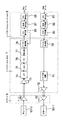
図8は、本発明の一実施の形態の記録再生系の主要部の回路ブロック図である。図8に示すように、磁気ディスク装置の記録再生系は、大きく分けて、ハードディスクコントローラ(HDC)8、リードチャネル(RDC)7、そしてプリアンプ6とからなる。(Signal recording / reproducing circuit)
FIG. 8 is a circuit block diagram of the main part of the recording / reproducing system according to the embodiment of the present invention. As shown in FIG. 8, the recording / reproducing system of the magnetic disk apparatus is roughly composed of a hard disk controller (HDC) 8, a read channel (RDC) 7, and a
記録系を説明する。記録データは、HDC8に入力する。HDC8内で、CRC符号器80は、記録データからCRC(Cyclic Redundacy Code)を作成し、記録データに作成したCRCパリテイを付加する。記録符号器82は、CRCパリテイを付加された記録データ列を、RLL(Run
Length Limited)符号などの拘束条件が満たされる列に変換する。そして、ECC符号器83は、記録符号器82の出力データ列に、ECC(Error
Correction Code)パリティを付加する。The recording system will be described. The recording data is input to the
Length Limited) is converted into a sequence that satisfies the constraint conditions such as code. Then, the
Correction Code) Adds parity.
HDC8のECC符号器83の出力データ列は、RDC7のマーカー符号器70に入力する。マーカー符号器70は、図9で後述するように、所定数の2ビットのマーカーを挿入し、符号化を行う。次に、ライト同期補償器71は、データ列を、ライトクロックに同期補正する。
The output data string of the
このライト同期補償されたデータ列は、ドライバ72を経由し、プリアンプ6に記録データを送出する。プリアンプ6では、ドライバ60が、記録ヘッド53−1へのライト電流を発生する。
This write synchronization compensated data string sends recording data to the
次に、再生系を説明する。再生ヘッド53−2からのアナログ電圧は、プリアンプ6のアンプ62によって、増幅された後、RDC7に出力される。RDC7においては、増幅されたアナログ信号が、可変利得アンプ(VGA:Variable Gain Amp)73、ローパスフィルタ(LPF)74、AD(アナログ・デジタル)コンバータ(ADC)75を経由して、デジタル信号へ変換される。
Next, the reproduction system will be described. The analog voltage from the reproducing head 53-2 is amplified by the amplifier 62 of the
FIR(Finite Response)フィルタ76が、PR波形等化を行った後、Viterbi検出器などの検出器77が、最尤復号を行う。マーカー復号器78は、後述するように、マーカー符号器70で挿入した2ビットマーカーを参考にして、Insertion/Deletionエラーを検出し、訂正を行う。
After a FIR (Finite Response)
マーカー復号器78から出力されたInsertion/Deletionエラー訂正後のビット列は、HDC8のECC復号器85へ入力される。ECC復号器85は、リードソロモン(RS)符号を用いて、誤り訂正を行う。ECC復号が成功した場合は、ECC復号器85の出力データ列は、記録復号器87、CRC復号器89を経て、再生データとして出力される。
The bit string after Insertion / Deletion error correction output from the
逆に、ECC復号が、失敗した場合は、ECC復号器85は、失敗フラグを、マーカー復号器78に出力する。失敗フラグを受け取ったマーカー復号器78は、近隣のセクタで発生したInsertion/Deletionエラーの発生位置情報を参考にしながら、Insertion/Deletionエラーの発生位置を予測して再訂正を行う。
On the contrary, when the ECC decoding fails, the
図9は、図8のマーカー符号器70のブロック図、図10は、図9の2ビットマーカーの説明図である。図9に示すように、マーカー符号器70の基本構成は、2ビットマーカー挿入部42と終端マーカー挿入部44からなる。又、必要に応じて、マーカー符号器70は、未挿入箇所計算部40を有する。
FIG. 9 is a block diagram of the
2ビットマーカー挿入部42は、1セクタ内の所定のデータ長に対し、2ビットのマーカー値(ここでは、図10のように、「10」)Mを付加する。例えば、セクタサイズが、4KByteサイズとし、ECC符号器で、1シンボル=12ビットのリードソロモン符号を用いることにする。
The 2-bit
ここでは、1セクタは、データセクタに、リードソロモン符号のパリティが付加された状態を表すことにする。図10は、1セクタ内でのマーカーの挿入状態を示し、2ビットマーカー挿入部42は、所定のデータ長に対し、2ビットマーカー値「10」を付加する。
Here, one sector represents a state in which the parity of the Reed-Solomon code is added to the data sector. FIG. 10 shows a marker insertion state in one sector, and the 2-bit
又、終端マーカー挿入部44は、セクタの終端において、12ビットのマーカー値「010010010010」を付加して、出力する。図10では、5シンボル=60ビットおきに、2ビットマーカー値「10」が付加され、セクタの終端には、12ビットのマーカー値「010010010010」が付加されている様子を示す。
The end
セクタの終端では、復号側で、2ビットマーカーでInsertionエラー又はDeletionエラーのどちらのエラーが発生したのかを判定するのは難しいため、12ビットのマーカーを付与している。この詳細は、後述する。 At the end of the sector, since it is difficult for the decoding side to determine whether an insertion error or a deletion error has occurred with a 2-bit marker, a 12-bit marker is added. Details of this will be described later.
次に、マーカー復号器78のマーカー復号原理を説明する。図11は、マーカー復号器78の2ビットマーカーのInsertion/Deletionエラーの訂正動作の説明図、図12は、マーカー復号器78の2ビットマーカーのInsertion/Deletionエラーの検出動作の説明図である。
Next, the marker decoding principle of the
マーカー復号器78は、マーカー値からInsertion/Deletionエラーの発生を検知する。図11は、1ビットの Insertionエラーが発生している様子を示す。Insertionエラーが発生するとシフトエラーが起こるためマーカー値が変化する。図12はInsertion/Deletionエラーなし、Insertionエラーあり、Deletionエラーありの3つの場合の2ビットマーカー値を示す。2ビットマーカー値は、Insertion/Deletionエラーなしの場合は、「10」の値をとり、Insertionエラーありの場合は、「01」、「11」いずれかの値をとり、Deletionエラーありの場合は、「01」、「00」のいずれかの値をとる。
The
図12から、Insertionエラーあり、Deletionエラーありの両方で、マーカー値が、「01」の値をもつため、マーカー値が、「01」である場合には、どちらのエラーが発生したかは、判別できない。例えば、図11の例では、「×」で示すInsertionエラーが発生した直後のマーカー値は、「01」のため、直後のマーカー値からでは、どちらのエラーが発生したかは判定できない。 From FIG. 12, since the marker value has the value “01” in both the insertion error and the deletion error, when the marker value is “01”, which error has occurred is: Cannot be determined. For example, in the example of FIG. 11, since the marker value immediately after the insertion error indicated by “x” is “01”, it cannot be determined which error has occurred from the immediately following marker value.
このため、図11に示すように、Insertionエラーが発生した直後のマーカー値以降の数サンプルのマーカー値を参考にして、どちらのエラーが発生したか判定する。図11では、8サンプルのマーカー値を調査して、どちらのエラーが発生したかを判定する。図11の例では、8サンプル中、4サンプルが、「01」、残りの4サンプルが、「11」を表している。 For this reason, as shown in FIG. 11, it is determined which error has occurred by referring to the marker values of several samples after the marker value immediately after the occurrence of the Insertion error. In FIG. 11, the marker values of 8 samples are examined to determine which error has occurred. In the example of FIG. 11, among the 8 samples, 4 samples represent “01” and the remaining 4 samples represent “11”.
Insertionエラーのみに発生するマーカー値「11」が、8サンプル中、4サンプルあるため、マーカー復号器78は、Insertionエラーが発生したと判定する。
Since the marker value “11” that occurs only in the insertion error is 4 out of 8 samples, the
ここで、Insertionエラー発生後のマーカー値が、「01」の値となる確率と、「11」の値となる確率とは、共に1/2となるため、サンプル数はそれほど多くする必要はない。 Here, since the probability that the marker value after the insertion error occurs is a value of “01” and the probability of a value of “11” are both ½, the number of samples does not need to be increased so much. .
また、この数サンプル参照する方法は、Insertion/Deletionエラーが、1回発生すると、しばらく、次のInsertion/Deletionエラーは発生しないという性質があるために、有効な方法である。 This method of referring to several samples is an effective method because there is a property that if an insertion / deletion error occurs once, the next insertion / deletion error does not occur for a while.
図13は、マーカー復号器78の終端マーカーのInsertion/Deletionエラーの訂正動作の説明図、図14は、マーカー復号器78の終端マーカーのInsertion/Deletionエラーの検出動作の説明図である。
FIG. 13 is an explanatory diagram of the operation of correcting the insertion marker / deletion error of the
図13に示すように、終端マーカー値は、12ビットの値である。図14は、Insertion/Deletionエラーなし、Insertionエラーあり、Deletionエラーありの3つの場合の終端マーカー値を示す。終端マーカー値は、Insertion/Deletionエラーなしの場合は、「010010010010」の値をとり、Insertionエラーありの場合は、「001001001001」、「101001001001」のいずれかの値をとり、Deletionエラーありの場合は、「100100100100」、「100100100101」のいずれかの値をとる。どの値も異なるため、1サンプルのみで判定できる。 As shown in FIG. 13, the end marker value is a 12-bit value. FIG. 14 shows the end marker values in the three cases of no insertion / deletion error, insertion error, and deletion error. The end marker value takes the value `` 010010010010 '' when there is no Insertion / Deletion error, takes one of the values `` 001001001001 '' and `` 101001001001 '' when there is an Insertion error, and if there is a Deletion error , “100100100100” or “100100100101”. Since each value is different, determination can be made with only one sample.
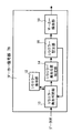
(マーカー復号器の第1の実施の形態)
図15は、マーカー復号器78の第1の実施の形態のブロック図である。図16は、2ビットマーカーのエラー検出動作の説明図、図17は、終端マーカーのエラー検出動作の説明図である。(First embodiment of marker decoder)
FIG. 15 is a block diagram of the
図15に示すように、マーカー復号器78の基本構成は、I(Insertion)/D(Deletion)エラー発生判定部10、I/Dエラー発生位置特定部14、I/Dエラー訂正部16、マーカー除去部18、I/Dエラー保存部12とを有する。
As shown in FIG. 15, the basic configuration of the
I/Dエラー発生判定部10は、図10で説明した8個のマーカーのうち、どのマーカー値の発生頻度が多いかを調べることにより、Insertion/Deletionエラーが発生したかどうかを判定する。
The I / D error
即ち、I/Dエラー発生判定部10は、I/Dエラーを表すマーカー値「01」、「11」、「00」が、8個のマーカーのうち、7個以上発生していた場合、I/Dエラー発生によるシフトエラーが発生したと判断し、Insertionエラー又はDeletionエラーのどちらのエラーが発生したのか判定を行う。I/Dエラーを表すマーカー値「01」、「11」、「00」が、8個のマーカーのうち、6個以下発生していた場合、I/Dエラー発生によるシフトエラーが発生しているかどうかが不明と判定する。
That is, the I / D error
また、I/Dエラー発生判定部10は、I/Dエラーなしを表すマーカー値「10」が、8個のマーカーのうち、6個以上ある場合、I/Dエラーなしと判定する。
Also, the I / D error
図16は、受信列の一例を示し、8個のマーカー(図の斜線で示す)ごとに、受信列を、4つの受信列に分割した状態を示す。図16の受信列の例を使って、I/Dエラー発生判定部10の判定方法をより詳細に説明する。
FIG. 16 shows an example of a reception sequence, and shows a state in which the reception sequence is divided into four reception sequences for each of 8 markers (indicated by hatching in the figure). The determination method of the I / D error
I/Dエラー発生判定部10は、最初に、AB区間の8個のマーカーを調べる。AB区間ではエラーなしを表す「10」のマーカーが7個、I/Dエラーを表す「11」のマーカーErが1個ある。I/Dエラーなしを表すマーカーが6個以上あるため、I/Dエラー発生判定部10は、AB区間は、I/Dエラーなしと判定する。
The I / D error
即ち、I/Dエラーを表す「11」のマーカーErが1個あっても、マーカーの通常エラーと判断し、AB区間には、Insertion/Deletionエラーはないと判定する。 That is, even if there is one “11” marker Er representing an I / D error, it is determined that the marker is a normal error, and it is determined that there is no Insertion / Deletion error in the AB section.
次に、I/Dエラー発生判定部10は、BC区間の8個のマーカーを調べる。BC区間では、エラーなしを表す「10」のマーカーが4個、I/Dエラーを表す「11」、「01」のマーカーErが4個ある。I/Dエラー発生判定部10は、I/Dエラー発生によるシフトエラーが発生しているかどうかが不明と判断する。
Next, the I / D error
次に、I/Dエラー発生判定部10は、CD区間の8個のマーカーを調べる。CD区間では、エラーなしを表す「10」のマーカーが1個、I/Dエラーを表す「11」、「01」、「00」のマーカーが7個ある。このため、I/Dエラー発生判定部10は、I/Dエラー発生によるシフトエラーが発生したと判断する。
Next, the I / D error
次に、I/Dエラー発生判定部10は、Insertionエラーが発生したのか、Deletionエラーが発生したのかを判定するために、Insertionエラーを表す「11」のマーカーと、Deletionエラーを表す「00」のマーカーの個数をカウントする。CD区間では、「11」のマーカーが1個、「00」のマーカーが1個と、同数のため、Insertionエラーが発生したのか、Deletionエラーが発生したのか判定できない。
Next, the I / D error
後述するI/Dエラー保存部12に、何も情報がない場合、I/Dエラー発生判定部10は、次のDE区間の8個のマーカーを調べる。DE区間では、「11」のマーカーが5個、「00」のマーカーが0個である。DE区間とCD区間のマーカーとを合計すると、「11」のマーカーが6個、「00」のマーカーが1個となる。
When there is no information in an I / D
「11」のマーカー数が多いため、I/Dエラー発生判定部10は、CD区間で、Insertionエラーの発生によりシフトエラーが発生したと判定し、CD区間内の「00」のマーカーは、通常誤りにより発生したと判断する。そして、I/Dエラー発生判定部10は、CD区間で、Insertionエラーの発生により、シフトエラーが発生しているという情報を出力する。さらに、I/Dエラー発生判定部10は、最後のI/Dエラーなしの区間は、AB区間であるという情報を出力する。
Since the number of markers “11” is large, the I / D error
また、I/Dエラー発生判定部10は、今回のInsertionエラーの発生が初回である場合、「このセクタではInsertionエラーが発生する」という情報を、I/Dエラー保存部12に保存する。
Further, the I / D error
前述のように、I/Dエラー発生判定部10は、CD区間でシフトエラーが発生したと判断した後、I/Dエラー保存部12を参照する。I/Dエラー保存部12に、「このセクタではInsertionエラーが発生する」(又は「このセクタではDeletionエラーが発生する」)という情報が保存されている場合、次のDE区間を調べずに、この情報から、CD区間で、Insertionエラー(又はDeletionエラー)の発生によりシフトエラーが発生したと判定する。
As described above, the I / D error
図2で説明したように、Insertionエラーが発生する場所と、Deletionエラーが発生する場所が分かれているため、1セクタ内にInsertionエラーとDeletionエラーの両方が発生することはなく、InsertionエラーのみかDeletionエラーのみが発生するという特性を持つ。このため、I/Dエラー保存部に情報がある場合、それを使用することができる。 As explained in Fig. 2, the place where the insertion error occurs and the place where the deletion error occurs are separated, so that both the insertion error and the deletion error do not occur in one sector. Only Deletion error occurs. For this reason, if there is information in the I / D error storage unit, it can be used.
次に、図17のセクタ終端部の受信列により、セクタ終端部のエラー検出動作を説明する。セクタ終端では、2ビットマーカーMで、Insertionエラー又はDeletionエラーのどちらのエラーが発生したのかを判定するのは難しい。このため、I/Dエラー発生判定部10は、終端マーカーMEを利用して、判定を行う。
Next, the error detection operation at the sector end portion will be described with reference to the reception sequence at the sector end portion in FIG. At the end of the sector, it is difficult to determine whether an insertion error or a deletion error has occurred with the 2-bit marker M. For this reason, the I / D error
即ち、I/Dエラー発生判定部10は、終端マーカーMEの「1」の数をカウントして判定を行う。図17の受信列では、終端マーカーMEの直前の2つの1ビットマーカーMが、I/Dエラーである値「01」である例を示す。
That is, the I / D error
図14の正常な終端マーカー値のテーブルと比較すると、図17の終端マーカー値MEは、I/Dエラーなしの状態で、「1」の値が立つ位置に、1個の「1」がある。又、Insertionエラーありの状態で、「1」の値が立つ位置に、4個の「1」があり、Deletionエラーありの状態での「1」の値が立つ位置に、0個の「1」がある。 Compared with the normal end marker value table of FIG. 14, the end marker value ME of FIG. 17 has one “1” at the position where the value of “1” stands in the state without an I / D error. . In addition, there are four “1” s at the position where the value “1” stands in the state with the insertion error, and zero “1” s at the position where the value “1” stands in the state with the deletion error. There is.
結果として、Insertionエラーありの状態での「1」の数が、その他の状態での「1」の数より、多くなる。このため、I/Dエラー発生判定部10は、セクタ終端で、Insertionエラーの発生によるシフトエラーが発生していると判定し、その情報を出力する。
As a result, the number of “1” in the state with the insertion error is larger than the number of “1” in the other states. For this reason, the I / D error
次に、図15のI/Dエラー発生位置特定部14を説明する。図18乃至図25は、I/Dエラー発生位置特定部14の動作説明図である。
Next, the I / D error occurrence
I/Dエラー発生位置特定部14は、I/Dエラー発生判定部10から出力されたInsertionエラー(又はDeletionエラー)によるシフトエラーが発生した区間情報と、最後のI/Dエラーなし区間情報を使って、Insertionエラー(又はDeletionエラー)の発生位置を特定する。
The I / D error occurrence
この発生位置の特定に、ハミング距離を用いた特定方法を用いる。図18乃至図20により、ハミング距離を用いた位置特定方法を説明する。I/Dエラー発生位置特定部14は、例えば、図16のように、最後のI/Dエラーなし区間は、AB区間であるという情報と、Deletionエラーによるシフトエラーが発生した区間はCD区間であるという情報を受けると、図18及び図19に示すように、両方の区間を含むAD区で、Insertion/Deletionエラーが発生していないマーカー列MA0を用意する。
A specifying method using a Hamming distance is used for specifying the generation position. A position specifying method using the Hamming distance will be described with reference to FIGS. For example, as shown in FIG. 16, the I / D error occurrence
このマーカー列MA0は、マーカー値が、正しい「10」である。I/Dエラー発生位置特定部14は、マーカー列MA0と受信列(AD区間)との間で、各マーカーのハミング距離を計算する。尚、図18及び図19では、マーカーを斜線で示し、その隣のブロックの数字は、ブロック番号を示す。例えば、1ブロックは、5シンボルで構成される。
This marker row MA0 has a correct marker value “10”. The I / D error occurrence
図18、図19の例では、AB区間での各マーカーのハミング距離の合計は、「0」、BC区間での各マーカーのハミング距離は、「5」、CD区間での各マーカーのハミング距離は、「11」であり、AD区間での合計値は、「16」となる。 In the example of FIGS. 18 and 19, the total Hamming distance of each marker in the AB section is “0”, the Hamming distance of each marker in the BC section is “5”, and the Hamming distance of each marker in the CD section. Is “11”, and the total value in the AD section is “16”.
次に、図19の受信列のCD区間の最後の位置(シンボル位置1)で、Deletionエラーが発生したと仮定した列MA1を用意する。図19に示すように、ブロック位置1のマーカー値を、図12のDeletionエラーのマーカー値に従い、「00」、「11」に変更する。
Next, a column MA1 assuming that a Deletion error has occurred is prepared at the last position (symbol position 1) of the CD section of the received column in FIG. As shown in FIG. 19, the marker value at
そして、同様に、I/Dエラー発生位置特定部14は、マーカー列MA1と受信列(AD区間)との間で、各マーカーのハミング距離を計算する。図18、図19の例では、AB区間での各マーカーのハミング距離の合計は、「0」、BC区間での各マーカーのハミング距離は、「5」、CD区間での各マーカーのハミング距離は、「9」であり、AD区間での合計値は、「14」となる。
Similarly, the I / D error occurrence
以下、同様に、ブロック位置2〜24の各々で、Deletionエラーが発生したと仮定した列MA2〜24を用意し、ハミング距離の計算を、シンボル位置2〜24でDeletionエラーが発生したと仮定した列MA2〜24と、受信列との間で計算する。
Hereinafter, similarly, columns MA2 to 24 assuming that a deletion error has occurred in each of the
図20は、各ブロック位置0〜24で、Deletionエラーが発生したと仮定した列MA0〜24と受信列との間で計算されたハミング距離の合計を、縦軸に、横軸にブロック位置を示したものである。尚、ブロック位置0は、Insertion/Deletionエラーが発生していないマーカー列MA0とのハミング距離である。
FIG. 20 shows the sum of the Hamming distances calculated between the columns MA0 to MA24 and the received column on the assumption that a Deletion error has occurred at each
図20に示すように、ハミング距離の合計は、ブロック位置「11」で最小値を示すため、I/Dエラー発生位置特定部14は、受信列のブロック番号「11」の位置で、Deletionエラーが発生したと判定し、発生位置を、I/Dエラー訂正部16に出力する。
As shown in FIG. 20, since the sum of the Hamming distances shows the minimum value at the block position “11”, the I / D error occurrence
次に、受信列がInsertion/Deletionエラーをもち、さらにマーカーに通常誤りがある例の位置特定を説明する。図21、図22は、受信列がInsertion/Deletionエラーをもち、さらにマーカーに通常誤りがある2つの受信列の例(受信列1、受信列2)を示す。図21、図22のマーカー値は、ブロック位置「9」、「11」の後のマーカー値のみ異なっており、前述のように、AD区間の受信列を示す。
Next, description will be given of the location of an example in which the reception sequence has an insertion / deletion error and the marker has a normal error. 21 and 22 show examples of two reception strings (
前述と同様に、受信列1、受信列2に対し、ハミング距離を計算し、ハミング距離の合計を計算する。図23は、図21の受信列1の各ブロック位置でのハミング距離の合計の結果を示す図である。図23に示すように、受信列1については、ブロック位置「12」で、ハミング距離の合計が、最小となるため、I/Dエラー発生位置特定部14は、ブロック位置「12」で、Deletionエラーが発生したと判定し、発生位置を出力する。
As described above, the Hamming distance is calculated for the
図24は、図22の受信列2の各ブロック位置でのハミング距離の合計の結果を示す図である。図24に示すように、受信列2では、ブロック位置「10」と「12」で、ハミング距離の合計が、最小の値をもつ。このため、I/Dエラー発生位置特定部14は、ブロック位置「10」〜「12」で、Deletionエラーが発生すると判定し、発生位置「10」〜「12」を出力する。
FIG. 24 is a diagram illustrating a total result of the Hamming distance at each block position in the
次に、セクタ終端でのハミング距離を用いたエラー位置特定処理を説明する。図25は、セクタ終端でのハミング距離を用いたエラー位置特定処理の受信列の説明図、図26は、そのブロック位置とハミング距離の合計との関係図である。図25の受信列は、Insertionエラーによるシフトエラーが発生している例を示す。 Next, an error position specifying process using the Hamming distance at the sector end will be described. FIG. 25 is an explanatory diagram of a reception sequence of the error position specifying process using the Hamming distance at the sector end, and FIG. 26 is a relationship diagram between the block position and the total Hamming distance. The received sequence in FIG. 25 shows an example in which a shift error due to an insertion error has occurred.
I/Dエラー発生位置特定部14は、2ビットマーカーの場合と基本的に同じ、ハミング距離の計算を行う。即ち、図25に示すように、Insertion/Deletionエラーが発生していない終端マーカーの参照列MA0を用意し、参照列MA0と受信列との間で各マーカーのハミング距離を計算する。図25の例では、各マーカーのハミング距離の合計が、「13」となる。
The I / D error occurrence
次に、図25の受信列のブロック番号1で、Insertionエラーが発生したと仮定した参照列MA1を用意する。参照列MA1は、シンボル番号1で、1ビット挿入されているため、終端マーカー値は、参照列MA0の終端マーカー値が、全体に1ビットシフトした値となる。そして、同様に、参照列MA1と受信列との間で各マーカーのハミング距離を計算する。図25の例では、各マーカーのハミング距離の合計が、「7」である。
Next, a reference string MA1 that assumes that an insertion error has occurred at
次に、図25の受信列の2ビットマーカーM2で、Insertionエラーが発生したと仮定した参照列MA2を用意し、参照列MA2と受信列との間で、各マーカーのハミング距離を計算する。図25の例では、各マーカーのハミング距離の合計が、「5」となる。 Next, a reference string MA2 that assumes that an Insertion error has occurred is prepared using the 2-bit marker M2 of the received string in FIG. 25, and the Hamming distance of each marker is calculated between the reference string MA2 and the received string. In the example of FIG. 25, the total Hamming distance of each marker is “5”.
同様の操作を続けていき、各ブロック番号に対するハミング距離の合計を計算した結果を図26に示す。図26に示すように、ブロック位置「4」で、ハミング距離の合計が、最小となる。I/Dエラー位置特定部14は、位置「4」で、Insertionエラーが発生したと判定し、発生位置を出力する。
FIG. 26 shows the result of calculating the total Hamming distance for each block number by continuing the same operation. As shown in FIG. 26, at the block position “4”, the total Hamming distance is minimum. The I / D error
次に、I/Dエラー訂正部16を説明する。図27及び図28は、I/Dエラー訂正動作の説明図である。I/Dエラー訂正部16は、I/Dエラー発生位置特定部14により出力されたI/Dエラー発生位置情報を元に、エラー訂正を行う。
Next, the I / D
例えば、図21の受信列1の例では、I/Dエラー発生位置特定部14は、図23に示したように、位置「12」で、Deletionエラーが発生していると判定した。
For example, in the example of the
I/Dエラー訂正部16は、これを受け、図27に示すように、受信列のブロック位置「12」の1ブロック(=5シンボル)の中の3シンボル目に、Deletionエラーが起きたと仮定する。
In response to this, the I / D
そして、Deletionエラーであるから、この1ブロックに1ビットを挿入する。例えば、3シンボル目に、1ビットを挿入し、全体をシフトする。強制的に、1ビットを挿入したため、誤りシンボルとなる可能性が高いことから、3シンボル目にイレージャーフラグを立てる。このイレージャーフラグは、ECC復号器85が、エラーの可能性のあるブロックとして、認識し、ECC訂正の際に、誤りを検出した時に、イレージャーフラグの立っているブロックを誤り位置として、訂正する。
Since it is a Deletion error, 1 bit is inserted into this 1 block. For example, 1 bit is inserted into the third symbol and the whole is shifted. Since one bit is forcibly inserted and there is a high possibility of an error symbol, an erasure flag is set at the third symbol. The erasure flag is recognized by the
一方、図22の受信列2の例では、I/Dエラー発生位置特定部14は、図24に示したように、位置「10」〜「12」でDeletionエラーが発生していると判定した。I/Dエラー訂正部16は、図28に示すように、受信列のブロック位置10〜12に、イレージャーフラグを立てる。さらに、受信列の位置12の最初のビット位置に、1ビットを挿入して、訂正を行う。
On the other hand, in the example of the
次に、訂正が完了した位置の次の区間から、I/Dエラー発生判定部10は、I/Dエラーが発生したかどうかの判定を続ける。I/Dエラーが発生していると判定した場合は、I/Dエラー発生位置特定部14が、位置の特定を行い、I/Dエラー訂正部16が、エラー訂正を行う。これらの操作は、セクタの終端に達するまで繰り返し行われ、全訂正を終了する。
Next, from the next section after the position where the correction is completed, the I / D error
訂正が完了したセクタデータは、マーカー除去部18に入力される。マーカー除去部18は、セクタデータから、すべての2ビットマーカーと終端マーカーを除去し、出力する。
The corrected sector data is input to the
このように、数サンプルのマーカー値の参照により、Insertion/Deletionエラーと、マーカーの通常エラーとの判別ができ、且つInsertion/Deletionエラー発生と判定した時に、そのサンプルのI/Dエラー値の数から、Insertionエラーであるか、Deletionエラーであるかを判別できる。 In this way, by referring to the marker values of several samples, it is possible to distinguish between insertion / deletion errors and normal marker errors, and when it is determined that an insertion / deletion error has occurred, the number of I / D error values for that sample From this, it can be determined whether it is an insertion error or a deletion error.
このようにマーカー復号器78は、複数のサンプルから状況に応じて、マーカーに、ビット誤りが発生したのか、InsertionエラーまたはDeletionエラーが発生したのかを判断して訂正を行う。
As described above, the
即ち、Insertion/Deletionエラーが1回発生すると、しばらく次のInsertion/Deletionエラーは発生しないという性質を利用し、2ビットマーカー方式に対し、マーカー上に通常の誤りがあるということを判定することができ、誤訂正を防止できる。また通常の誤りであるかどうかがわからない箇所には、イレージャーフラグを立てることによって、誤訂正を防ぐ。 In other words, using the property that once an insertion / deletion error occurs, the next insertion / deletion error does not occur for a while, it is possible to determine that there is a normal error on the marker for the 2-bit marker method. This can prevent erroneous correction. In addition, an erasure flag is set at a place where it is not known whether or not it is a normal error, thereby preventing erroneous correction.
更に、Insertionエラーが発生する場所と、Deletionエラーが発生する場所が分かれているという性質を利用し、1セクタに1回目のInsertionエラー又はDeletionエラーが発生した場合、どちらのエラーが発生したか記憶し、2回目以降に、Insertion/Deletionエラーが発生した場合、1回目の記憶情報を参考にして、Insertionエラー、Deletionエラーのどちらのエラーが発生したかを判定する。これにより、誤訂正を防ぐことができる。 Furthermore, using the property that the place where the insertion error occurs and the place where the deletion error occurs are separated, if one insertion error or deletion error occurs in one sector, which error occurred is stored. If an Insertion / Deletion error occurs after the second time, it is determined whether an Insertion error or a Deletion error has occurred with reference to the first storage information. Thereby, erroneous correction can be prevented.
(マーカー復号器の第2の実施の形態)
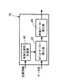
図29は、本発明のマーカー復号器の第2の実施の形態のブロック図、図30は、図29の実施の形態の未挿入箇所計算部の説明図である。図29のマーカー復号器78において、図15で説明したものと同一のものは、同一の記号で示してあり、マーカー復号器78は、I(Insertion)/D(Deletion)エラー発生判定部10、I/Dエラー発生位置特定部14、I/Dエラー訂正部16、マーカー除去部18、I/Dエラー保存部12とを有する。(Second embodiment of marker decoder)
FIG. 29 is a block diagram of the second embodiment of the marker decoder of the present invention, and FIG. 30 is an explanatory diagram of an uninserted portion calculation unit of the embodiment of FIG. In the
更に、マーカー復号器78は、位置情報からマーカー未挿入箇所を検出する未挿入箇所計算部20と、第2のI/Dエラー発生位置特定部22とを有する。
Further, the
第2のI/Dエラー発生位置特定部22は、後述するように、ECC復号器85が、セクタの復号が失敗した場合、近隣のセクタで発生したInsertion/Deletionエラーの発生位置情報を受け、その情報を参考にしながら、Insertion/Deletionエラーの発生位置を予測して、I/Dエラー訂正部16に再訂正を行わせる。この機能により、誤り訂正能力が向上する。
As will be described later, the second I / D error occurrence
未挿入箇所計算部20は、図9のマーカー符号器70の未挿入箇所計算部40に関連する。即ち、ライト同期の位相が調整された後、しばらくはInsertion/Deletionエラーは発生しない。そこでライト同期の位相が調整された後、しばらくは、2ビットのマーカーを挿入しないようにする。
The non-inserted
この2ビットマーカーの未挿入について、図30で説明する。図30は、磁気ディスク3の1トラックのサーボ領域90とデータ領域92の説明図である。図30に示すように、1つのトラック3−1上に、複数のサーボ領域90とデータ領域92とが設けられ、ライトクロックを含めた位相は、サーボ単位で調整される。
This non-insertion of the 2-bit marker will be described with reference to FIG. FIG. 30 is an explanatory diagram of the servo area 90 and the
このため、ライトクロックは、サーボ領域90のサーボ信号で、磁気ディスク3の回転速度に合わせて、同期化されるため、データ領域92の先頭から、しばらくはInsertion/Deletionエラーは発生しない。即ち、データ領域92の先頭から、しばらくは、ライトクロックと、磁気ディスク3の記録ドットとのずれが生じない。
For this reason, the write clock is synchronized with the servo signal of the servo area 90 in accordance with the rotation speed of the
このため、ずれが生じない部分に、2ビットマーカーを挿入することは意味がない。そこで、この部分には、2ビットマーカーの挿入を行わないようにすることで、冗長度を減らすことが可能となる。 For this reason, it is meaningless to insert a 2-bit marker in a portion where no deviation occurs. Therefore, it is possible to reduce redundancy by not inserting a 2-bit marker in this portion.
この未挿入処理を行う場合は、サーボ領域とデータ領域とセクタの位置関係を、メモリなどにあらかじめ記録しておき、未挿入位置にあたるかを判定する。 When this non-insertion process is performed, the positional relationship between the servo area, the data area, and the sector is recorded in advance in a memory or the like, and it is determined whether the non-insertion position is reached.
例えば、データ領域92の先頭とセクタの先頭が同じであり、データ領域92の先頭から、10000ビット目までは、Insertion/Deletionエラーは発生しないとすると、以下のように冗長度を減らして符号化率を向上させることができる。
For example, if the beginning of the
一例として、以下の条件を設定して、符号化率を計算する。先ず、セクタサイズ:4KByte=32000ビット、未挿入処理なし:60ビット(5シンボル)に、2ビットマーカーを挿入、未挿入処理あり:最初の10000ビットには、2ビットマーカーを挿入せず、10001ビット以降、60ビットに、2ビットマーカーを挿入の条件とする。 As an example, the following conditions are set and the coding rate is calculated. First, sector size: 4 KBytes = 32000 bits, no insertion processing: 2-bit marker is inserted into 60 bits (5 symbols), non-insertion processing is performed: 2-bit marker is not inserted into the first 10,000 bits, 10001 After the bit, a 2-bit marker is inserted as a condition for 60 bits.
このとき、挿入ビットの総数は、未挿入処理なし:1066ビット、未挿入処理あり:734ビットとなる。 At this time, the total number of inserted bits is 1066 bits without insertion processing and 734 bits with insertion processing.
このため、符号化率は、未挿入処理なし:32000/(32000+1066)≒0.967となる。一方、未挿入処理あり:32000/(32000+734)≒0.977となる。このように、未挿入処理ありの場合は、未挿入処理なしの場合に比べて、符号化率が、0.01向上する。 For this reason, the coding rate is no insertion processing: 32000 / (32000 + 1066) ≈0.967. On the other hand, there is no insertion processing: 32000 / (32000 + 734) ≈0.977. As described above, when the non-insertion process is performed, the coding rate is improved by 0.01 compared with the case where the non-insertion process is not performed.
この2ビットマーカーの未挿入処理を行う場合、図9で示したように、マーカー符号器70に、未挿入箇所計算部40を付け加える。未挿入箇所計算部40には、メモリからの位置関係情報を入力する。入力された位置関係情報から、データ領域の先頭が、セクタの何ビット目になるか計算する。
When performing the non-insertion process of the 2-bit marker, an uninserted
例えば、計算結果からデータ領域の先頭が、セクタの100ビット目になることがわかった場合、200ビット目から10100ビット目までの間には、2ビットマーカーを挿入しないように、開始位置・終了位置情報(開始位置, 終了位置)=(200ビット目,10100ビット目)を、2ビットマーカー挿入部42に出力する。
For example, if it is found from the calculation result that the head of the data area is the 100th bit of the sector, the start position / end is set so that a 2-bit marker is not inserted between the 200th bit and the 10100th bit. Position information (start position, end position) = (200th bit, 10100th bit) is output to the 2-bit
2ビットマーカー挿入部42は、入力された開始位置・終了位置情報を使って、入力されたデータ列の200ビット目から10100ビット目までの間には、2ビットマーカーを挿入しない処理をする。
The 2-bit
この開始位置が、100ビット目ではなく、200ビット目から行う理由は、もし、100ビット目の直前で、Insertion/Deletionエラーが発生した場合、マーカーがないと、誤りを検知することができない問題があるためである。 The reason for starting from the 200th bit instead of the 100th bit is that if an insertion / deletion error occurs immediately before the 100th bit, an error cannot be detected without a marker. Because there is.
同様に、図29のマーカー復号器78に、未挿入箇所計算部20を付け加える。未挿入箇所計算部20には、メモリからの位置関係情報を入力する。入力された位置関係情報から、データ領域の先頭が、セクタの何ビット目になるか計算する。
Similarly, an uninserted
例えば、計算結果からデータ領域の先頭が、セクタの100ビット目になることがわかった場合、200ビット目から10100ビット目までの間には、2ビットマーカーのエラーを検出しないように、開始位置・終了位置情報(開始位置, 終了位置)=(200ビット目,10100ビット目)を、I/Dエラー発生判定部10に出力する。
For example, if it is found from the calculation result that the head of the data area is the 100th bit of the sector, the start position is not detected between the 200th bit and the 10100th bit so that a 2-bit marker error is not detected. End position information (start position, end position) = (200th bit, 10100th bit) is output to the I / D error
I/Dエラー発生判定部10は、入力された開始位置・終了位置情報を使って、入力されたデータ列の200ビット目から10100ビット目までの間には、2ビットマーカーのI/Dエラーを検出しない処理をする。
The I / D error
次に、図29の第2のI/Dエラー発生位置特定部22を使用した復号方法について、説明する。あるトラック上のあるデータ領域で、Insertion/Deletionエラーが発生した場合、近隣のトラックや近隣のデータ領域上でも、ほぼ同じ地点で、Insertion/Deletionエラーが発生する確率が高い。即ち、トラック・データ領域と、Insertion/Deletionエラー発生地点とは相関があると考えられる。
Next, a decoding method using the second I / D error occurrence
このため、リードソロモン(ECC)復号器85で、あるセクタの復号が失敗した場合、再リードにより、近隣のセクタ(同一トラック又は、隣接トラック)の復号を行い、復号により得られたInsertion/Deletionエラーの発生位置の情報を、メモリに記憶する。
For this reason, when decoding of a certain sector fails in the Reed-Solomon (ECC)
リードソロモン復号が失敗したセクタを、マーカー復号器78が、再復号する際、メモリに記憶されたエラーの発生位置の情報を使って、Insertion/Deletionエラーの発生位置を特定し、訂正を行う。
When the
このInsertion/Deletionエラーの発生位置の情報を得るには、サーボ領域・データ領域とセクタの位置関係が判明している必要があり、メモリなどにあらかじめそれらの位置関係情報を記録しておく。 In order to obtain information on the occurrence position of this insertion / deletion error, it is necessary to know the positional relationship between the servo area / data area and the sector, and the positional relationship information is recorded in advance in a memory or the like.
この第2のI/Dエラー発生位置特定部22を使用した復号方法では、I/Dエラー発生判定部10、I/Dエラー発生位置特定部14、未挿入箇所計算部20、I/Dエラー保存部12は使用しない。
In the decoding method using the second I / D error occurrence
第2のI/Dエラー発生位置特定部22は、リードソロモン復号失敗フラグと、I/Dエラー発生位置情報を受け取り、Insertion/Deletionエラーが発生していると思われるビット位置を特定する。
The second I / D error occurrence
例えば、第2のI/Dエラー発生位置特定部22は、1つ目の他セクタからのI/Dエラー発生位置情報により、20100ビット目に、Insertionエラーが発生すると判定し、2つ目の他セクタからのI/Dエラー発生位置情報により、20120ビット目に、Insertionエラーが発生すると判定した場合、20081ビット目から20140ビット目までの区間に、Insertionエラーが発生すると判定する。
For example, the second I / D error occurrence
そして、第2のI/Dエラー発生位置特定部22は、開始・終了位置情報(開始位置, 終了位置)=(20081,20140)を、I/Dエラー訂正部16に出力する。開始・終了位置情報が入力されたI/Dエラー訂正部16は、20081ビット目から20140ビット目までの区間を含むシンボルに対し、イレージャーフラグを立て、20081ビット目を削除して訂正を行う。
Then, the second I / D error occurrence
その後、マーカー除去部18で、各マーカーを除去して出力する。
Thereafter, the
このように、セクタの復号が失敗した場合、近隣のセクタで発生したInsertion/Deletionエラーの発生位置情報を受け、その情報を参考にしながら、Insertion/Deletionエラーの発生位置を予測して、再訂正を行う機能を付け加える。この機能により誤り訂正能力が向上する。 In this way, when sector decoding fails, it receives information on the position of the insertion / deletion error that occurred in the neighboring sector, predicts the position of the insertion / deletion error, and recorrects it with reference to that information. Add the function to perform. This function improves error correction capability.
又、ライト同期の位相が調整された後、しばらくはInsertion/Deletionエラーは発生しない。そこでライト同期の位相が調整された後、しばらくは、2ビットのマーカーを挿入しないようにする。 Also, Insertion / Deletion errors do not occur for a while after the write synchronization phase is adjusted. Therefore, after the phase of the write synchronization is adjusted, a 2-bit marker is not inserted for a while.
(他の実施の形態)
上述の実施の形態では、ディスク装置として、ビットパターンド媒体を用いた磁気ディスク装置で説明したが、他のライト同期により、記録を行うディスク装置にも適用できる。又、2ビットマーカーの参照サンプル数を、8で説明したが、複数、望ましくは、4サンプル以上であれば、良い。(Other embodiments)
In the above-described embodiment, the magnetic disk device using the bit patterned medium is described as the disk device. However, the present invention can also be applied to a disk device that performs recording by other write synchronization. The number of reference samples of the 2-bit marker has been described as 8. However, a plurality of, preferably 4 or more samples may be used.
更に、誤り訂正を、リードソロモン符号を用いた例で説明したが、LDPC(低密度パリテイ符号)など他の誤り訂正方法を採用できる。 Further, although error correction has been described with an example using a Reed-Solomon code, other error correction methods such as LDPC (low density parity code) can be employed.
以上、本発明の実施の形態により説明したが、本発明は、上述の実施の形態に限られず、本発明の趣旨の範囲において、種々の変形が可能であり、これらを、本発明の範囲から排除するものではない。 As described above, the embodiments of the present invention have been described. However, the present invention is not limited to the above-described embodiments, and various modifications can be made within the scope of the present invention. It is not excluded.
データ列に挿入された2ビットマーカーの複数のサンプルの状況に応じて、マーカーに、ビット誤りが発生したのか、InsertionエラーまたはDeletionエラーが発生したのかを判断して訂正を行うため、2ビットマーカーを用いて、符号化率を向上するとともに、2ビットマーカーを用いても、マーカーの誤りによる、誤訂正によるシフトエラーを防止でき、バーストエラーを防止できる。 2-bit marker to determine whether a bit error, Insertion error or Deletion error has occurred in the marker according to the status of multiple samples of 2-bit marker inserted in the data string As a result, the coding rate can be improved, and even if a 2-bit marker is used, a shift error due to erroneous correction due to a marker error can be prevented, and a burst error can be prevented.
Claims (5)
前記データ列から前記2ビットのマーカーをサンプルし、複数のマーカーのサンプル値から、前記マーカー上の誤りか、インサーションエラーであるか、デリーションエラーであるかを判定するマーカー復号器と、
前記マーカー復号器からのデータ列の誤り訂正を、前記データ列の誤り訂正符号を用いて行う誤り訂正器とを有し、
前記マーカー復号器は、
前記データ列から前記2ビットのマーカーをサンプルし、3個以上のマーカーのサンプル値から、前記マーカー上の誤りか、インサーションエラーであるか、デリーションエラーであるかを判定するI/Dエラー発生判定部と、
前記I/Dエラー発生判定部からの前記インサーションエラー又は前記デリーションエラーの判定結果を受け、前記3個以上のマーカーのサンプル値から、前記インサーションエラー又は前記デリーションエラーの発生位置を特定する位置特定部と、
前記データ列の前記特定されたエラー発生位置のエラー訂正を行うI/Dエラー訂正部と、
前記エラー訂正されたデータ列から、前記2ビットのマーカーを除去するマーカー除去部とを有する
ことを特徴とする誤り訂正回路。An error correction circuit that receives a data sequence in which a plurality of 2-bit markers are inserted at a predetermined number of bits and corrects an error,
A marker decoder that samples the 2-bit marker from the data sequence and determines whether the error is on the marker, an insertion error, or a deletion error from sample values of a plurality of markers;
An error corrector that performs error correction of the data string from the marker decoder using an error correction code of the data string;
The marker decoder is
An I / D error that samples the 2-bit marker from the data string and determines whether it is an error on the marker, an insertion error, or a deletion error from the sample values of three or more markers An occurrence determination unit;
In response to the insertion error or the deletion error determination result from the I / D error generation determination unit, the occurrence position of the insertion error or the deletion error is specified from the sample values of the three or more markers. A position identifying unit to perform,
An I / D error correction unit that performs error correction of the specified error occurrence position of the data string;
An error correction circuit comprising: a marker removal unit that removes the 2-bit marker from the error-corrected data string.
前記ディスク記憶装置は、データ列に対し、予め決められたビット数間隔で、複数の2ビットのマーカーを挿入するマーカー符号器と、前記マーカー符号器からのデータ列を、回転するディスク媒体に記録し、前記ディスク媒体から前記記録された前記データ列を読み出すヘッドとを有し、 The disk storage device records on a rotating disk medium a marker encoder that inserts a plurality of 2-bit markers at a predetermined number of bits with respect to a data string, and a data string from the marker encoder. And a head for reading the recorded data string from the disk medium,
前記誤り訂正回路は、前記ヘッドから読み出された前記データ列を受信し、受信したデータ列を、誤り訂正の対象とし、 The error correction circuit receives the data string read from the head, the received data string is an error correction target,
前記ディスク媒体が、記録ドットが孤立して形成されたビットパターンド媒体からなる The disk medium is a bit patterned medium in which recording dots are formed in isolation.
ことを特徴とする請求項1に記載の誤り訂正回路。 The error correction circuit according to claim 1.
前記マーカー符号器からのデータ列を、回転するディスク媒体に記録し、前記ディスク媒体から前記記録された前記データ列を読み出すヘッドと、
前記ヘッドから読み出された前記データ列から前記2ビットのマーカーをサンプルし、複数のマーカーのサンプル値から、前記マーカー上の誤りか、インサーションエラーであるか、デリーションエラーであるかを判定するマーカー復号器と、
前記マーカー復号器からのデータ列の誤り訂正を、前記データ列の誤り訂正符号を用いて行う誤り訂正器とを有し、
前記マーカー復号器は、
前記データ列から前記2ビットのマーカーをサンプルし、3個以上のマーカーのサンプル値から、前記マーカー上の誤りか、インサーションエラーであるか、デリーションエラーであるかを判定するI/Dエラー発生判定部と、
前記I/Dエラー発生判定部からの前記インサーションエラー又は前記デリーションエラーの判定結果を受け、前記3個以上のマーカーのサンプル値から、前記インサーションエラー又は前記デリーションエラーの発生位置を特定する位置特定部と、
前記データ列の前記特定されたエラー発生位置のエラー訂正を行うI/Dエラー訂正部と、
前記エラー訂正されたデータ列から、前記2ビットのマーカーを除去するマーカー除去部とを有する
ことを特徴とするディスク記憶装置。A marker encoder that inserts a plurality of 2-bit markers at a predetermined number of bits into the data sequence;
A head for recording a data string from the marker encoder on a rotating disk medium and reading the recorded data string from the disk medium;
The 2-bit marker is sampled from the data string read from the head, and it is determined from the sample values of a plurality of markers whether the error is on the marker, an insertion error, or a deletion error A marker decoder to
An error corrector that performs error correction of the data string from the marker decoder using an error correction code of the data string;
The marker decoder is
An I / D error that samples the 2-bit marker from the data string and determines whether it is an error on the marker, an insertion error, or a deletion error from the sample values of three or more markers An occurrence determination unit;
In response to the insertion error or the deletion error determination result from the I / D error generation determination unit, the occurrence position of the insertion error or the deletion error is specified from the sample values of the three or more markers. A position identifying unit to perform,
An I / D error correction unit that performs error correction of the specified error occurrence position of the data string;
A disk storage device comprising: a marker removing unit that removes the 2-bit marker from the error-corrected data string.
前記マーカー符号器からのデータ列を、回転するディスク媒体に記録し、前記ディスク媒体から前記記録された前記データ列を読み出すヘッドと、
前記ヘッドから読み出された前記データ列から前記2ビットのマーカーをサンプルし、複数のマーカーのサンプル値から、前記マーカー上の誤りか、インサーションエラーであるか、デリーションエラーであるかを判定するマーカー復号器と、
前記マーカー復号器からのデータ列の誤り訂正を、前記データ列の誤り訂正符号を用いて行う誤り訂正器とを有し、
前記マーカー復号器は、前記インサーションエラーである、又は前記デリーションエラーであると判定した場合に、前記インサーションエラー、又は前記デリーションエラーの誤り訂正を行い、且つ前記2ビットのマーカーを除去したデータ列を出力し、前記マーカー符号器は、前記ディスクに記録する前記データ列の前記インサーションエラー又はデリーションエラーの発生しないデータに対し、前記2ビットのマーカーの挿入を禁止する
ことを特徴とするディスク記憶装置。A marker encoder that inserts a plurality of 2-bit markers at a predetermined number of bits into the data sequence;
A head for recording a data string from the marker encoder on a rotating disk medium and reading the recorded data string from the disk medium;
The 2-bit marker is sampled from the data string read from the head, and it is determined from the sample values of a plurality of markers whether the error is on the marker, an insertion error, or a deletion error A marker decoder to
An error corrector that performs error correction of the data string from the marker decoder using an error correction code of the data string;
When the marker decoder determines that the insertion error is or the deletion error, the marker decoder corrects the insertion error or the deletion error and removes the 2-bit marker. And the marker encoder prohibits the insertion of the 2-bit marker into the data that does not cause the insertion error or the deletion error of the data sequence to be recorded on the disc. A disk storage device.
ことを特徴とする請求項3または4に記載のディスク記憶装置。The disk storage device according to claim 3 or 4, wherein the disk medium is a bit patterned medium in which recording dots are formed in isolation.
Applications Claiming Priority (1)
| Application Number | Priority Date | Filing Date | Title |
|---|---|---|---|
| PCT/JP2009/000855 WO2010097834A1 (en) | 2009-02-26 | 2009-02-26 | Error correction circuit and disk storage device |
Publications (2)
| Publication Number | Publication Date |
|---|---|
| JPWO2010097834A1 JPWO2010097834A1 (en) | 2012-08-30 |
| JP5073052B2 true JP5073052B2 (en) | 2012-11-14 |
Family
ID=42665064
Family Applications (1)
| Application Number | Title | Priority Date | Filing Date |
|---|---|---|---|
| JP2010506723A Expired - Fee Related JP5073052B2 (en) | 2009-02-26 | 2009-02-26 | Error correction circuit and disk storage device |
Country Status (3)
| Country | Link |
|---|---|
| US (1) | US8386888B2 (en) |
| JP (1) | JP5073052B2 (en) |
| WO (1) | WO2010097834A1 (en) |
Families Citing this family (2)
| Publication number | Priority date | Publication date | Assignee | Title |
|---|---|---|---|---|
| US9354970B2 (en) * | 2014-03-31 | 2016-05-31 | Advanced Micro Devices, Inc. | Method and apparatus for encoding erroneous data in an error correction code protected memory |
| US9373349B1 (en) * | 2015-05-29 | 2016-06-21 | Seagate Technology Llc | Relaxing media design constraints with two-dimensional magnetic recording |
Citations (5)
| Publication number | Priority date | Publication date | Assignee | Title |
|---|---|---|---|---|
| JPS63157372A (en) * | 1986-12-19 | 1988-06-30 | Matsushita Electric Ind Co Ltd | Information recording and reproducing device |
| JPH0346167A (en) * | 1989-07-14 | 1991-02-27 | Matsushita Electric Ind Co Ltd | Demodulation circuit |
| JPH07176139A (en) * | 1993-10-28 | 1995-07-14 | Philips Electron Nv | Transmitter-receiver of digital information signal |
| JP2008299975A (en) * | 2007-05-31 | 2008-12-11 | Toshiba Corp | Disk storage device and data error correction method |
| US20090003144A1 (en) * | 2007-06-29 | 2009-01-01 | Seagate Technology Llc | Method and system for error checking in a bit-patterned media |
Family Cites Families (4)
| Publication number | Priority date | Publication date | Assignee | Title |
|---|---|---|---|---|
| EP0624990B1 (en) * | 1993-05-12 | 1999-03-31 | Matsushita Electric Industrial Co., Ltd. | Video recording and reproducing apparatus |
| EP0655850A3 (en) | 1993-10-28 | 1995-07-19 | Philips Electronics Nv | Transmission and reception of a digital information signal. |
| EP1082721B1 (en) * | 1999-03-23 | 2003-07-30 | Koninklijke Philips Electronics N.V. | Method of decoding a stream of channel bits of a signal relating to a binary channel signal into a stream of source bits of a signal relating to a binary source signal |
| US7667912B2 (en) * | 2007-07-03 | 2010-02-23 | Seagate Technology Llc | Retry and re-read for write synchronization |
-
2009
- 2009-02-26 JP JP2010506723A patent/JP5073052B2/en not_active Expired - Fee Related
- 2009-02-26 WO PCT/JP2009/000855 patent/WO2010097834A1/en active Application Filing
-
2010
- 2010-08-03 US US12/849,722 patent/US8386888B2/en not_active Expired - Fee Related
Patent Citations (5)
| Publication number | Priority date | Publication date | Assignee | Title |
|---|---|---|---|---|
| JPS63157372A (en) * | 1986-12-19 | 1988-06-30 | Matsushita Electric Ind Co Ltd | Information recording and reproducing device |
| JPH0346167A (en) * | 1989-07-14 | 1991-02-27 | Matsushita Electric Ind Co Ltd | Demodulation circuit |
| JPH07176139A (en) * | 1993-10-28 | 1995-07-14 | Philips Electron Nv | Transmitter-receiver of digital information signal |
| JP2008299975A (en) * | 2007-05-31 | 2008-12-11 | Toshiba Corp | Disk storage device and data error correction method |
| US20090003144A1 (en) * | 2007-06-29 | 2009-01-01 | Seagate Technology Llc | Method and system for error checking in a bit-patterned media |
Also Published As
| Publication number | Publication date |
|---|---|
| US20100296379A1 (en) | 2010-11-25 |
| US8386888B2 (en) | 2013-02-26 |
| WO2010097834A1 (en) | 2010-09-02 |
| JPWO2010097834A1 (en) | 2012-08-30 |
Similar Documents
| Publication | Publication Date | Title |
|---|---|---|
| JP3663377B2 (en) | Data storage device, read data processing device, and read data processing method | |
| US7562282B1 (en) | Disk drive employing error threshold counters to generate an ECC error distribution | |
| US7800853B1 (en) | Correcting servo sectors in a disk drive | |
| JP4814925B2 (en) | Data recording method, recording medium, and reproducing apparatus | |
| US9489260B1 (en) | Flexible super block sizing for failed sector recovery | |
| US9143168B1 (en) | Method and system for removing interference caused by servo data from user data | |
| US7322003B2 (en) | Information storage device | |
| US6462898B2 (en) | Disk drive with information encoded in the position error signal fields | |
| US7941729B2 (en) | Data storage device and error processing method in its read processing | |
| US7131052B2 (en) | Algebraic decoder and method for correcting an arbitrary mixture of burst and random errors | |
| JP2007528566A (en) | Error correction encoding method and apparatus, and error correction decoding method and apparatus | |
| JP5073052B2 (en) | Error correction circuit and disk storage device | |
| US20100241922A1 (en) | Error correction circuit and data storage device | |
| EP2843662A1 (en) | Systems and methods for multi-level encoding and decoding | |
| US20120198304A1 (en) | Information reproduction apparatus and information reproduction method | |
| JP2010287271A (en) | Error correcting method and data reproducing device | |
| US9257146B1 (en) | Data storage device comprising sequence detector compensating for inter-track interference | |
| US9633691B2 (en) | Storage controller, storage device, and method | |
| JP2005209286A (en) | Data recording method, recording medium, and reproducing device | |
| JP4238425B2 (en) | Disk drive device and servo information detection method | |
| KR100734294B1 (en) | Method and apparatus for detecting and restoring defective region and disk drive using the same | |
| CN109509488B (en) | Storage device and recording medium control method | |
| JP2003257134A (en) | Signal reproducing method and signal reproducing device |
Legal Events
| Date | Code | Title | Description |
|---|---|---|---|
| A131 | Notification of reasons for refusal |
Free format text: JAPANESE INTERMEDIATE CODE: A131 Effective date: 20120522 |
|
| A521 | Written amendment |
Free format text: JAPANESE INTERMEDIATE CODE: A523 Effective date: 20120628 |
|
| TRDD | Decision of grant or rejection written | ||
| A01 | Written decision to grant a patent or to grant a registration (utility model) |
Free format text: JAPANESE INTERMEDIATE CODE: A01 Effective date: 20120724 |
|
| A01 | Written decision to grant a patent or to grant a registration (utility model) |
Free format text: JAPANESE INTERMEDIATE CODE: A01 |
|
| A61 | First payment of annual fees (during grant procedure) |
Free format text: JAPANESE INTERMEDIATE CODE: A61 Effective date: 20120821 |
|
| FPAY | Renewal fee payment (event date is renewal date of database) |
Free format text: PAYMENT UNTIL: 20150831 Year of fee payment: 3 |
|
| LAPS | Cancellation because of no payment of annual fees |