JP5072425B2 - Image forming apparatus and sheet stacking control method - Google Patents
Image forming apparatus and sheet stacking control method Download PDFInfo
- Publication number
- JP5072425B2 JP5072425B2 JP2007122533A JP2007122533A JP5072425B2 JP 5072425 B2 JP5072425 B2 JP 5072425B2 JP 2007122533 A JP2007122533 A JP 2007122533A JP 2007122533 A JP2007122533 A JP 2007122533A JP 5072425 B2 JP5072425 B2 JP 5072425B2
- Authority
- JP
- Japan
- Prior art keywords
- sheets
- stacking
- sheet
- print job
- image forming
- Prior art date
- Legal status (The legal status is an assumption and is not a legal conclusion. Google has not performed a legal analysis and makes no representation as to the accuracy of the status listed.)
- Active
Links
- 238000000034 method Methods 0.000 title claims description 42
- 230000008569 process Effects 0.000 claims description 27
- 230000008859 change Effects 0.000 claims description 3
- 238000010586 diagram Methods 0.000 description 12
- 230000006870 function Effects 0.000 description 11
- 238000001514 detection method Methods 0.000 description 10
- 230000002093 peripheral effect Effects 0.000 description 9
- 230000015572 biosynthetic process Effects 0.000 description 5
- 230000032258 transport Effects 0.000 description 3
- 238000004140 cleaning Methods 0.000 description 1
- 238000007599 discharging Methods 0.000 description 1
- 238000005516 engineering process Methods 0.000 description 1
- 238000010438 heat treatment Methods 0.000 description 1
- 230000007246 mechanism Effects 0.000 description 1
- 230000007704 transition Effects 0.000 description 1
- 238000011144 upstream manufacturing Methods 0.000 description 1
Images


Classifications
-
- B—PERFORMING OPERATIONS; TRANSPORTING
- B65—CONVEYING; PACKING; STORING; HANDLING THIN OR FILAMENTARY MATERIAL
- B65H—HANDLING THIN OR FILAMENTARY MATERIAL, e.g. SHEETS, WEBS, CABLES
- B65H39/00—Associating, collating, or gathering articles or webs
- B65H39/10—Associating articles from a single source, to form, e.g. a writing-pad
-
- B—PERFORMING OPERATIONS; TRANSPORTING
- B65—CONVEYING; PACKING; STORING; HANDLING THIN OR FILAMENTARY MATERIAL
- B65H—HANDLING THIN OR FILAMENTARY MATERIAL, e.g. SHEETS, WEBS, CABLES
- B65H33/00—Forming counted batches in delivery pile or stream of articles
- B65H33/06—Forming counted batches in delivery pile or stream of articles by displacing articles to define batches
- B65H33/08—Displacing whole batches, e.g. forming stepped piles
-
- G—PHYSICS
- G03—PHOTOGRAPHY; CINEMATOGRAPHY; ANALOGOUS TECHNIQUES USING WAVES OTHER THAN OPTICAL WAVES; ELECTROGRAPHY; HOLOGRAPHY
- G03G—ELECTROGRAPHY; ELECTROPHOTOGRAPHY; MAGNETOGRAPHY
- G03G15/00—Apparatus for electrographic processes using a charge pattern
- G03G15/50—Machine control of apparatus for electrographic processes using a charge pattern, e.g. regulating differents parts of the machine, multimode copiers, microprocessor control
-
- G—PHYSICS
- G03—PHOTOGRAPHY; CINEMATOGRAPHY; ANALOGOUS TECHNIQUES USING WAVES OTHER THAN OPTICAL WAVES; ELECTROGRAPHY; HOLOGRAPHY
- G03G—ELECTROGRAPHY; ELECTROPHOTOGRAPHY; MAGNETOGRAPHY
- G03G15/00—Apparatus for electrographic processes using a charge pattern
- G03G15/65—Apparatus which relate to the handling of copy material
- G03G15/6552—Means for discharging uncollated sheet copy material, e.g. discharging rollers, exit trays
-
- B—PERFORMING OPERATIONS; TRANSPORTING
- B65—CONVEYING; PACKING; STORING; HANDLING THIN OR FILAMENTARY MATERIAL
- B65H—HANDLING THIN OR FILAMENTARY MATERIAL, e.g. SHEETS, WEBS, CABLES
- B65H2405/00—Parts for holding the handled material
- B65H2405/10—Cassettes, holders, bins, decks, trays, supports or magazines for sheets stacked substantially horizontally
- B65H2405/15—Large capacity supports arrangements
-
- B—PERFORMING OPERATIONS; TRANSPORTING
- B65—CONVEYING; PACKING; STORING; HANDLING THIN OR FILAMENTARY MATERIAL
- B65H—HANDLING THIN OR FILAMENTARY MATERIAL, e.g. SHEETS, WEBS, CABLES
- B65H2511/00—Dimensions; Position; Numbers; Identification; Occurrences
- B65H2511/10—Size; Dimensions
-
- B—PERFORMING OPERATIONS; TRANSPORTING
- B65—CONVEYING; PACKING; STORING; HANDLING THIN OR FILAMENTARY MATERIAL
- B65H—HANDLING THIN OR FILAMENTARY MATERIAL, e.g. SHEETS, WEBS, CABLES
- B65H2511/00—Dimensions; Position; Numbers; Identification; Occurrences
- B65H2511/30—Numbers, e.g. of windings or rotations
-
- B—PERFORMING OPERATIONS; TRANSPORTING
- B65—CONVEYING; PACKING; STORING; HANDLING THIN OR FILAMENTARY MATERIAL
- B65H—HANDLING THIN OR FILAMENTARY MATERIAL, e.g. SHEETS, WEBS, CABLES
- B65H2511/00—Dimensions; Position; Numbers; Identification; Occurrences
- B65H2511/40—Identification
- B65H2511/415—Identification of job
-
- B—PERFORMING OPERATIONS; TRANSPORTING
- B65—CONVEYING; PACKING; STORING; HANDLING THIN OR FILAMENTARY MATERIAL
- B65H—HANDLING THIN OR FILAMENTARY MATERIAL, e.g. SHEETS, WEBS, CABLES
- B65H2513/00—Dynamic entities; Timing aspects
- B65H2513/50—Timing
- B65H2513/51—Sequence of process
-
- B—PERFORMING OPERATIONS; TRANSPORTING
- B65—CONVEYING; PACKING; STORING; HANDLING THIN OR FILAMENTARY MATERIAL
- B65H—HANDLING THIN OR FILAMENTARY MATERIAL, e.g. SHEETS, WEBS, CABLES
- B65H2515/00—Physical entities not provided for in groups B65H2511/00 or B65H2513/00
- B65H2515/20—Volume; Volume flow
-
- B—PERFORMING OPERATIONS; TRANSPORTING
- B65—CONVEYING; PACKING; STORING; HANDLING THIN OR FILAMENTARY MATERIAL
- B65H—HANDLING THIN OR FILAMENTARY MATERIAL, e.g. SHEETS, WEBS, CABLES
- B65H2801/00—Application field
- B65H2801/03—Image reproduction devices
- B65H2801/06—Office-type machines, e.g. photocopiers
-
- G—PHYSICS
- G03—PHOTOGRAPHY; CINEMATOGRAPHY; ANALOGOUS TECHNIQUES USING WAVES OTHER THAN OPTICAL WAVES; ELECTROGRAPHY; HOLOGRAPHY
- G03G—ELECTROGRAPHY; ELECTROPHOTOGRAPHY; MAGNETOGRAPHY
- G03G2215/00—Apparatus for electrophotographic processes
- G03G2215/00362—Apparatus for electrophotographic processes relating to the copy medium handling
- G03G2215/00367—The feeding path segment where particular handling of the copy medium occurs, segments being adjacent and non-overlapping. Each segment is identified by the most downstream point in the segment, so that for instance the segment labelled "Fixing device" is referring to the path between the "Transfer device" and the "Fixing device"
- G03G2215/00417—Post-fixing device
- G03G2215/00421—Discharging tray, e.g. devices stabilising the quality of the copy medium, postfixing-treatment, inverting, sorting
Description
本発明は、画像形成装置から排出される用紙を複数の用紙積載手段へ積載する際の積載制御に関する。 The present invention relates to stacking control when stacking sheets discharged from an image forming apparatus on a plurality of sheet stacking units.
近年、シート(用紙)に画像を形成する画像形成装置では、画像形成技術の進歩向上により画像形成速度の高速化が図られて、画像形成装置の装置本体からシートを高速、かつ大量に排出することができるようになった。このため、画像形成装置の装置本体に接続されて、装置本体から排出されるシートを受け取って積載するシート積載装置においても、シートの積載整合性を維持して、多量のシートを積載できることが求められている。こうした要請に応えたシート積載装置(以下「スタッカ装置」と言う)が、例えば特許文献1に記載されている。
In recent years, in an image forming apparatus that forms an image on a sheet (paper), the image forming speed has been increased by the advancement of image forming technology, and a large number of sheets are discharged from the main body of the image forming apparatus at high speed. I was able to do it. For this reason, even in a sheet stacking apparatus that is connected to the apparatus main body of the image forming apparatus and receives and stacks sheets discharged from the apparatus main body, it is required that a large number of sheets can be stacked while maintaining sheet stacking consistency. It has been. A sheet stacking apparatus (hereinafter referred to as a “stacker apparatus”) that meets such a request is described in, for example,
図22は、この従来のスタッカ装置の構成を示す側断面図である。 FIG. 22 is a side sectional view showing the configuration of this conventional stacker apparatus.
スタッカ装置500では、画像形成装置の装置本体から排出されたシートを、入口ローラ501で受け取った後、搬送ローラ対502でグリッパ503に引き渡す。グリッパ503は、シートを把持して搬送し、シートの先端を先端ストッパ504に突き当てる。シートは、先端ストッパ504に突き当たると、グリッパ503から外れて、用紙積載台505の上に落下する。このとき、シートは、先端ストッパ504と後端ストッパ508との間に落下して、先端と後端とが整合される。また、必要に応じて不図示の幅整合機構によって幅整合されて、シート搬送方向と直角な方向のシート端部(側端部)を揃えられる。
In the
また、このような従来のスタッカ装置においては、用紙積載台505に順次積載されたシートの枚数が積載可能な最大枚数に達したり、最大枚数に達する前にジョブが終了したりすると、用紙積載台505に積載されたシートが、取り出し可能な状態となる。
ところで、上記従来のスタッカ装置におけるシートの積載容量を増やしたい場合、スタッカ装置を複数台用意し、これらを連結して使用することが考えられる。 By the way, when it is desired to increase the sheet stacking capacity in the conventional stacker apparatus, it is conceivable to prepare a plurality of stacker apparatuses and use them by connecting them.
図23は、連結された2つのスタッカ装置500a,500bを示す図である。
FIG. 23 is a diagram illustrating two connected
このように複数のスタッカ装置500a,500bを連結して使用する場合において、スタッカ装置500aおよびスタッカ装置500bの最大積載枚数がそれぞれ、例えば5000枚であるとする。そして、10ページの原稿からなる冊子を1部として1000部の冊子分のシートの印刷を、グループモードで行うプリントジョブが入力された場合を想定する。なお、グループモードとは、1部がNページ(Nは整数)のシートを部数M(Mは整数)形成するプリントジョブにおいて、同じページのシートをM枚まとめたN個のグループとしてシートを積載するモードである。例えば、10ページからなる原稿をそれぞれ部数5だけ印刷する場合に、同一ページの原稿が印刷されたシートが5枚ずつの束となってページ順に積載される。この場合、1つのページの原稿を設定部数分連続して印刷する動作が各ページ毎に繰り返される。
When a plurality of
このプリントジョブを実行すると、まず、原稿の第1〜第5ページが1000枚ずつ順次スタッカ装置505bに積載される。これによって、5000枚の上限積載量となるので、今度は、スタッカ装置505aに対して、原稿の第6〜第10ページが1000枚ずつ順次積載される。
When this print job is executed, first, the first to fifth pages of the document are sequentially stacked on the
ここで、スタッカ装置505aに対して原稿の第6〜第10ページ分のシートが積載されている間に、満載になったスタッカ装置505bを外部に運び出して、原稿10ページからなる冊子の作成作業を行おうとしたとする。この場合、スタッカ装置505bには、原稿の第6〜第10ページ分のシートが積載されていないので、こうした冊子の作成作業を行うことができない。そのため、スタッカ装置505aに対する原稿の第6〜第10ページのシートの積載を待つ必要があり、作業性が低いという問題があった。
Here, while the sheets for the sixth to tenth pages of the document are stacked on the
本発明はこのような問題点に鑑みてなされたものであって、複数ページからなる原稿を複数部数、グループモードで画像形成する場合において、第1の用紙積載装置に用紙を積載している最中に、用紙が満載になった第2の用紙積載装置を外部に取り出して、次工程の処理を行うことを可能にした画像形成装置及びシート積載制御方法を提供することを目的とする。 The present invention has been made in view of such problems, and in the case of forming an image of a plurality of pages of a document in a group mode with a plurality of copies, the first sheet stacking apparatus is loaded with sheets. It is an object of the present invention to provide an image forming apparatus and a sheet stacking control method capable of taking out the second sheet stacking apparatus full of sheets to the outside and performing the next process.
上記目的を達成するために、本発明による画像形成装置は、入力されたプリントジョブに基づいてシートに画像をプリントする画像形成手段と、前記画像形成手段によりプリントされたシートを積載するシート積載手段と、1〜Nページ(Nは整数)の画像をそれぞれM枚(Mは整数)プリントするプリントジョブにおいて、各ページのシートをそれぞれM枚重ねたN個のグループとしてシートを積載するグループモードが設定されている場合に、前記プリントジョブでプリントされるシートの総枚数が前記シート積載手段の上限積載量よりも多ければ、前記プリントジョブを複数のプリント動作に分割する制御手段とを有し、前記複数のプリント動作の各々は1〜Nページの画像をそれぞれMよりも少ない枚数プリントする動作であることを特徴とする。
また、本発明による画像形成装置は、入力されたプリントジョブに基づいてシートに画像をプリントする画像形成手段と、前記画像形成手段によりプリントされたシートを積載するシート積載手段と、1〜Nページ(Nは整数)の画像をそれぞれM枚(Mは整数)プリントするプリントジョブにおいて、各ページのシートをそれぞれM枚重ねたN個のグループとしてシートを積載するグループモードが設定されている場合に、前記プリントジョブでプリントされるシートの総枚数が前記シート積載手段の上限積載量よりも多ければ、前記プリントジョブにおけるプリント順序を、1〜Nページの画像をそれぞれMよりも少ない枚数プリントする動作を繰り返すように変更する制御手段とを有することを特徴とする。
In order to achieve the above object, an image forming apparatus according to the present invention includes an image forming unit that prints an image on a sheet based on an input print job, and a sheet stacking unit that stacks a sheet printed by the image forming unit. In a print job in which images of 1 to N pages (N is an integer) are printed on M sheets (M is an integer), there is a group mode in which sheets are stacked as N groups each including M sheets of each page. Control means for dividing the print job into a plurality of printing operations if the total number of sheets printed in the print job is greater than the upper limit stacking capacity of the sheet stacking means when set , Each of the plurality of printing operations is an operation of printing images of 1 to N pages less than M respectively. And features.
An image forming apparatus according to the present invention includes an image forming unit that prints an image on a sheet based on an input print job, a sheet stacking unit that stacks sheets printed by the image forming unit, and 1 to N pages. In a print job that prints M (N is an integer) images (N is an integer), when a group mode is set in which sheets are stacked as N groups in which M sheets of each page are overlaid. If the total number of sheets to be printed in the print job is larger than the upper limit stacking capacity of the sheet stacking unit, the printing order in the print job is the number of images of 1 to N pages printed less than M each. And control means for changing to repeat.
本発明によるシート積載制御方法は、入力されたプリントジョブに基づいてシートに画像をプリントする画像形成手段と、前記画像形成手段によりプリントされたシートを積載するシート積載手段とを有する画像形成装置に適用されるシート積載制御方法であって、1〜Nページ(Nは整数)の画像をそれぞれM枚(Mは整数)プリントするプリントジョブにおいて、各ページのシートをそれぞれM枚重ねたN個のグループとしてシートを積載するグループモードが設定されているか否かを判断する判断工程と、前記プリントジョブでプリントされるシートの総枚数と前記シート積載手段の上限積載量とを比較する比較工程と、前記グループモードが設定されている場合に、前記総枚数が前記上限積載量よりも多ければ、前記プリントジョブを複数のプリント動作に分割する分割工程と、を有し、前記複数のプリント動作の各々は1〜Nページの画像をそれぞれMよりも少ない枚数プリントする動作であることを特徴とする。 A sheet stacking control method according to the present invention includes an image forming unit that prints an image on a sheet based on an input print job, and a sheet stacking unit that stacks a sheet printed by the image forming unit. A sheet stacking control method to be applied, in a print job in which M images (M is an integer) are printed on each of 1 to N pages (N is an integer), and N sheets each having M sheets stacked on each page. A determination step of determining whether a group mode for stacking sheets as a group is set, a comparison step of comparing the total number of sheets printed in the print job and the upper limit stacking amount of the sheet stacking unit, wherein when the group mode has been set, the more than the total number is the upper limit load amount, the print job A division step of dividing the plurality of printing operation, wherein the each of the plurality of printing operation, characterized in that the image of 1~N page is an operation for smaller number printed than M, respectively.
また、本発明によるシート積載制御方法は、入力されたプリントジョブに基づいてシートに画像をプリントする画像形成手段と、前記画像形成手段によりプリントされたシートを積載するシート積載手段とを有する画像形成装置に適用されるシート積載制御方法であって、1〜Nページ(Nは整数)の画像をそれぞれM枚(Mは整数)プリントするプリントジョブにおいて、各ページのシートをそれぞれM枚重ねたN個のグループとしてシートを積載するグループモードが設定されているか否かを判断する判断工程と、前記プリントジョブでプリントされるシートの総枚数と前記シート積載部の上限積載量とを比較する比較工程と、前記グループモードが設定されている場合に、前記総枚数が前記上限積載量よりも多ければ、前記プリントジョブにおけるプリント順序を、1〜Nページの画像をMよりも少ない枚数プリントする動作を繰り返すように変更する変更工程と、を有することを特徴とする。 The sheet stacking control method according to the present invention includes an image forming unit that prints an image on a sheet based on an input print job, and an image forming unit that stacks a sheet printed by the image forming unit. A sheet stacking control method applied to an apparatus, in which M sheets of each page are overlapped in a print job in which M images (M is an integer) of 1 to N pages (N is an integer) are printed. A determination step of determining whether or not a group mode for stacking sheets as a group is set , and a comparison step of comparing the total number of sheets printed in the print job with the upper limit stacking amount of the sheet stacking unit If, when the group mode has been set, the greater the total number than the upper limit load capacity, the printed-di The print order in Bed, characterized by having a a changing step of changing the image of 1~N page to repeat the operation for a small number of print than M.
本発明によれば、複数ページからなる原稿を複数部数、グループモードで画像形成する場合において、一つの積載手段にシートを積載している最中に、シートが満載になった別の積載手段を外部に取り出して、次工程の処理を行うことが可能となる。したがって、作業性が向上する。 According to the present invention, multiple copies of a document including a plurality of pages, in a case where the image forming a group mode, the midst of stacking sheets in a stacking unit, another stacking means sheet becomes full It can be taken out and processed in the next process. Therefore, workability is improved.
以下、本発明を実施するための最良の形態について、図面を参照して説明する。 The best mode for carrying out the present invention will be described below with reference to the drawings.
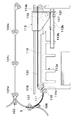
図1は、本発明の一実施の形態に係る画像形成装置の構成を示す断面図である。この断面図は、画像形成装置のシート(用紙)搬送方向に沿った断面図である。 FIG. 1 is a cross-sectional view showing a configuration of an image forming apparatus according to an embodiment of the present invention. This cross-sectional view is a cross-sectional view along the sheet (paper) conveyance direction of the image forming apparatus.
(画像形成装置)
画像形成装置900は、装置本体(画像形成部)900Aにシート積載装置(シート積載手段、以下「スタッカ装置)という)100を備えている。スタッカ装置100は、装置本体900Aにオプションとして接続されるようになっているが、装置本体900A内に組み込まれる構成であってもよい。
(Image forming device)
The
装置本体900Aは、イメージリーダ951と自動原稿送り装置950とを上部に備えている。給紙カセット902a乃至902eにセットされたシートSは、給紙ローラ903a乃至903e、搬送ローラ対904によってレジストレーションローラ(以下、レジストローラと称す)対910まで搬送される。
The apparatus
一方、感光体ドラム906は、一次帯電器907によって帯電されている状態で、露光部908によって露光されて、イメージリーダ951で読み取られた原稿のデジタル原稿データが静電潜像として形成される。そして、現像器909が、感光体ドラム906に形成された静電潜像をトナー画像にトナー現像する。
On the other hand, the
そして、トナー画像の位置に合わせて、シートがレジストローラ対910によって感光体ドラム906と転写器905との間に、送り込まれる。転写器905は、トナー画像を感光体ドラム906からシートに転写する。シートに転写されずに感光体ドラム906に付着している残存トナー等の異物は、クリーニング装置913のブレードで掻き落とされる。この結果、感光体ドラム906の表面は清掃されて、次の画像形成に備えられる。
Then, the sheet is fed between the
トナー画像を転写されたシートは、搬送ベルト911によって定着器912に搬送されて、定着器912の加熱ローラと加圧ローラとに狭持されて加熱加圧され、トナー画像がシートに定着される。トナー画像を定着されたシートは、そのまま、排紙ローラ対914により、スタッカ装置100に搬送されるか、または、フラッパ915により両面反転装置901に搬送されて、再度、反対側の面にもトナー画像が形成される。
The sheet to which the toner image has been transferred is conveyed to the
(制御装置)
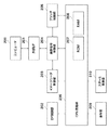
図2は、画像形成装置900の動作を制御する制御装置の構成を示すブロック図である。
(Control device)
FIG. 2 is a block diagram illustrating a configuration of a control device that controls the operation of the
CPU回路部206は、CPU(図示せず)、ROM207、RAM208を内蔵し、ROM207に格納されている制御プログラムにより、各ブロック202,209,203,204,201,205,210を総括的に制御する。RAM208は、制御データを一時的に保持し、また制御に伴う演算処理の作業領域として用いられる。
The
DF(原稿給紙)制御部202は、CPU回路部206からの指示に基づいて自動原稿送り装置950を駆動制御する。イメージリーダ制御部203は、上述のイメージリーダ951内のスキャナユニット、イメージセンサなどに対する駆動制御を行い、イメージセンサから出力されたアナログ画像信号を画像信号制御部204に転送する。
A DF (document feeding)
画像信号制御部204は、イメージセンサからのアナログ画像信号をデジタル信号に変換した後に各処理を施し、このデジタル信号をプリント用のビデオ信号に変換してプリンタ制御部205に出力する。また、画像信号制御部204は、コンピュータ200から外部I/F201を介して入力されたデジタル画像信号に各種処理を施して、プリント用のビデオ信号に変換してプリンタ制御部205に出力する。画像信号制御部204による処理動作は、CPU回路部206により制御される。
The image
プリンタ制御部205は、入力されたビデオ信号に基づき上述の露光部908を駆動制御する。
The
操作部209は、画像形成に関する各種機能を設定するための複数のキー、設定状態を示す情報を表示するための表示部などを有している。操作部209は、各キーの操作に対応するキー信号をCPU回路部206に出力するとともに、CPU回路部206からの信号に基づき、操作画面を操作部209の表示部に表示する。この表示部に表示される操作画面を用いて、各種モードの設定が行われるが、これについては、図3および図4を参照して後述する。
The
スタッカ制御部210は、スタッカ装置100に搭載され、CPU回路部206と情報の授受を行うことによって、スタッカ装置100全体の駆動制御を行うようになっている。スタッカ制御部210については、図5を参照して後述する。
The
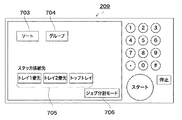
図3および図4は、画像形成装置900の操作部209に表示される第1および第2の操作画面をそれぞれ示す図である。これらの操作画面を用いて、各種モードを設定する操作手順を説明する。
3 and 4 are diagrams showing first and second operation screens displayed on the
図3に示す第1の操作画面におけるキー701は、画像形成後のシートの積載方法(積載モード)を設定するためのキーであり、キー701を押下すると、図4に示す第2の操作画面に遷移する。 A key 701 in the first operation screen illustrated in FIG. 3 is a key for setting a sheet stacking method (stacking mode) after image formation. When the key 701 is pressed, the second operation screen illustrated in FIG. 4 is displayed. Transition to.
図4に示す第2の操作画面におけるキー703はソートモードを、キー704はグループモードを設定するためのキーである。ソートモードは、部単位にシートをソートして積載するモードであり、グループモードは、ページ単位にシートをグルーピングして積載するモードである。例えば、原稿がA,B,Cの3ページからなり、これを2部印刷する場合、ソートモードでは、A,B,C;A,B,Cという順で印刷が行われ、グループモードでは、A,A;B,B;C,Cという順で印刷が行われる。 The key 703 on the second operation screen shown in FIG. 4 is a key for setting the sort mode, and the key 704 is a key for setting the group mode. The sort mode is a mode in which sheets are sorted and stacked in units of copies, and the group mode is a mode in which sheets are grouped and stacked in units of pages. For example, when a document consists of three pages of A, B, and C and is printed in two copies, printing is performed in the order of A, B, and C; A, B, and C in sort mode, and in group mode, Printing is performed in the order of A, A; B, B; C, C.
また、キー705は、シートの排紙先を指定するキーである。排紙先の「トレイ1」はスタッカトレイ112a、「トレイ2」はスタッカトレイ112b、「トップトレイ」はトップトレイ106(図6を参照して後述)に対応する。
A key 705 is a key for designating a sheet discharge destination. “
キー706は、ジョブ分割積載モードを選択するためのキーである。ジョブ分割積載モードについては、図19〜図21を参照して詳しく後述する。 A key 706 is a key for selecting a job division stacking mode. The job division stacking mode will be described in detail later with reference to FIGS.
図5は、スタッカ制御部210の内部構成およびスタッカ制御部210に接続される各種センサ、モータ、ソレノイドを示すブロック図である。
FIG. 5 is a block diagram showing an internal configuration of the
スタッカ制御部210は、CPU回路部170やドライバ部171などにより構成される。ドライバ部171には、各種モータ150〜156や各種ソレノイド160,161が接続される。また、CPU回路部170には、各種センサ131,111,113a,113b,117が接続される。以下に、CPU回路部170によって実施される制御の内容について説明する。
The
(スタッカ装置の基本動作)
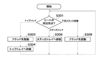
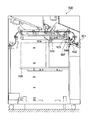
図6は、スタッカ装置100の構成を示す断面図であり、図7は、スタッカ装置100の基本動作を示すフローチャートである。以下、図5〜図7を参照しながら、スタッカ装置100の動作およびCPU回路部170で実施される制御内容を説明する。
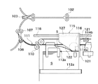
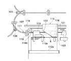
(Basic operation of the stacker unit)
6 is a cross-sectional view showing the configuration of the
画像形成装置900の装置本体900A(図1)から排出されたシートは、図6に示すように、スタッカ装置100の入口ローラ対101によりスタッカ装置100内に搬送される。そして、搬送ローラ対102a〜102dにより切換えフラッパ103まで搬送される。入口ローラ対101および搬送ローラ対102a〜102dは、入口搬送モータ150(図5)により駆動される。シートが搬送される前に、図2に示す画像形成装置900のCPU回路部206からは、予めスタッカ制御部210にシートに関するシート情報が送られる。シート情報は、シートサイズ、紙種、シートの排出先等の属性を示す情報である。
The sheet discharged from the apparatus
図7に示すように、スタッカ制御部210のCPU回路部170は、送られたシート情報に基づき、シートの排出先を判別する(S301)。その結果、シートの排出先がトップトレイ106(図6)であるならば、ステップS303へ進み、スタッカトレイ112a,112b(図6)であるならば、ステップS306へ進む。また、シートの排出先が、スタッカ装置100のさらに下流に設けられたスタッカ装置(不図示)であるならば、ステップS308へ進む。
As shown in FIG. 7, the
ステップS303では、CPU回路部170は、図6に示すように、切換えフラッパ103をフラッパソレノイド160(図5)により、破線で示す先端下向きの位置に切換え、シートを搬送ローラ対104に導く。CPU回路部170は、、搬送モータ151(図5)を駆動してシートを排紙ローラ対105によりトップトレイ106に排出させて、積載させる(S304)。
In step S <b> 303, as shown in FIG. 6, the
ステップS306では、CPU回路部170は、図6に示すように、シートをスタッカトレイ112a,112b(図6)に排紙させる。すなわち、搬送ローラ対102dにより搬送されたシートは、フラッパソレノイド160(図5)で、実線で示す先端上向きに切換った切換えフラッパ103に案内されて、搬送ローラ対107によって搬送される。そして、シートは、実線で示す上端左向きに切換った出口切換えフラッパ108によって、排紙ローラ対110に案内される。この排紙ローラ対110によりシートは、グリッパ114a,114bに受け渡され、スタッカトレイ112a,112bに選択的に排出されて積載される。この排出動作の詳細については後述する。
In step S306, the
ステップS308では、CPU回路部170は、図6に示すように、出口切換えフラッパ108を破線で示す上端右向きの位置に切換る。搬送ローラ対102dにより搬送されてきたシートは、搬送ローラ対107により搬送されて、出口ローラ対109に導かれた後、下流のスタッカ装置に搬送される。
In step S308, as shown in FIG. 6, the
(シートをスタッカトレイに排出する動作)
スタッカ装置100は、シートを積載する2つのスタッカトレイ(シート積載トレイ)112a,112bを有していて、スタッカトレイ112a,112bへ選択的にシートを排出する。スタッカトレイ112a,112bはそれぞれスモールサイズ(A4サイズ以下)のシートを積載可能である。また、スタッカトレイ112a,112bの両方を使用してラージサイズ(B4,A3サイズ)のシートも積載可能である。
(Operation to discharge the sheet to the stacker tray)
The
次に、シートをスタッカトレイ112a,112bに対して選択的に排出する動作を説明する。
Next, an operation for selectively discharging sheets to the
図6を参照して、スタッカ装置100におけるスタッカトレイ112a,112bの周辺の構成を説明する。
A configuration around the
スタッカトレイ112a,112bは、スタッカトレイ昇降モータ152a、スタッカトレイ昇降モータ152b(図5)により、矢印C,D,E,F方向にそれぞれ昇降可能に配置される。
The
引込みユニット115はフレーム127を含み、フレーム127が、スライド軸118に沿って移動可能であり、引込みユニット115は、引き込みモータ153(図5)により、矢印A,B方向に移動するようになっている。引込みユニット115のフレーム127は、シートの先端を突き当てるストッパ121と、シートをストッパ121に案内するテーパ部122とから形成される。引込みユニット115はさらに、シートをストッパ121に引き込む、弾性を備えたローレットベルト116も含む。
The retracting
ローレットベルト116は、ローレットベルトモータ154(図5)により、反時計回りに回転して、ローレットベルト116とスタッカトレイ112a(または、スタッカトレイ112b)との間にシートを引き込む。これによって、シートの先端がストッパ121に突き当てられる。紙面検知センサ117は、引込みユニット115に組み込まれたセンサであり、引込みユニット115からシート上面までの距離を一定に保つために使用される。
The
グリッパ114a,114bはシートの先端部を把持してシートを搬送するものであり、不図示の捩りコイルばねにより、シートを把持する方向に付勢された状態で駆動ベルト130に取付けられている。排出ローラ対110により排出されたシートがグリッパ114a,114bに押込まれることにより、シートが保持される構成になっている。なお、グリッパ114a,114bは、V字状に開口した部材の開口部内の上下にスポンジなどの弾性体を設け、その上下の弾性体の間に押し込まれたシートを保持するような構成であってもよい。
The
スタッカトレイ112a,112bは、排出されたシートが積載されるトレイであり、シートを積載するためのホームポジション位置に待機する構成になっている。すなわち、スタッカトレイ112a,112bの位置が、ホーム位置検出センサ113a,113bによってそれぞれ検出され、その検出結果に応じて、スタッカトレイ112a,112bはホームポジション位置に移動される。
The
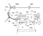
図8〜図11は、図6に示すスタッカ装置100におけるスタッカトレイ112aの周辺構成をそれぞれ示す第1〜第4の断面図である。
8 to 11 are first to fourth cross-sectional views respectively showing the peripheral configuration of the
図8に示すように、画像形成装置900の装置本体900A(図1)から排出されたシートSは、排出ローラ対110まで搬送される。そしてシートは、排出ローラ対110の上流に配置されているタイミングセンサ111により、先端の通過タイミングが検知される。この検知タイミングで、停止待機しているグリッパ114aが、シートSの先端部を把持する。これに同期して、駆動ベルト130が循環を開始して、図9に示すように、グリッパ114aがシートを把持したまま引き込みユニット115に接近移動する。
As shown in FIG. 8, the sheet S discharged from the apparatus
そして、図10に示すように、グリッパ114aが引込みユニット115のテーパ部122を通過すると、シートSは、グリッパ114aから外れて、搬送されてきた勢いで、テーパ部122に案内されて、スタッカトレイ112a側に付勢される。そして、シートは、ローレットベルト116とスタッカトレイ112a(シートが既にスタッカトレイ112aに積載されているときには、その最上位のシート)との間に進入する。その後、図11に示すようにローレットベルト116によりシートSは、先端部がストッパ121に突き当たるまで搬送される。この結果、シートSは、先端を揃えられて(整合されて)、スタッカトレイ112a上または最上のシート上に積載されることになる。
Then, as shown in FIG. 10, when the
その後、整合板119が、シート搬送方向と直角な方向(シートの幅方向)にジョギング動作を行い、シートの側端を揃える(幅整合する)。
Thereafter, the
紙面検知センサ117は、スタッカトレイ112aに積載されたシートの上面を常時監視している。引込みユニット115のローレットベルト116とシートとの間隔が、所定量よりも狭くなった場合、スタッカトレイ昇降モータ152aによりスタッカトレイ112aが所定量下降させられる。これによって、ローレットベルト116とシートとの間隔が所定の間隔に保持される。
The paper
スタッカ装置100では、駆動ベルトモータ155(図5)により駆動される駆動ベルト130が循環して、2つのグリッパ114a,114bが交互にシートを排出搬送して、スタッカトレイ112aにシートを順次積載する。
In the
スタッカトレイ112a上に積載されたシートの満載は、次のようにして検知される。すなわち、まず、排出ローラ対110から排出されるシートSをタイミングセンサ111が検知し、これをスタッカ制御部210(図2)でカウントして、積載されるシートの枚数を検出する。そして検出された積載シート枚数を、予め設定されている積載枚数の上限値と比較することで、積載されたシートの満載を検知する。本実施の形態では、スタッカトレイ112a,112bにおける普通紙の最大積載枚数が、例えば5000枚である。そして、上記の上限値は、画像形成装置900の操作部209、またはコンピュータ200上の不図示の操作画面より入力され、最大積載枚数以下の値に設定される。
The full load of sheets stacked on the
なお、スタッカトレイ112aに対するシートの積載開始から経過した時間である積載時間を測定し、該積載時間を、予め設定されている積載時間の上限値と比較することで、積載されたシートの満載を検知するようにしてもよい。
In addition, the stacking time, which is the time elapsed from the start of stacking of sheets on the
さらに、スタッカトレイ112aの下降位置と最上位のシートの位置とを検知して、積載されたシートの満載を検知するようにしてもよい。
Furthermore, the full position of the stacked sheets may be detected by detecting the lowered position of the
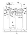
スタッカトレイ112a上のシートが満載になった場合、図12に示すように、スタッカ制御部210(図2)がスタッカトレイ112aを下降させ、積載されたシートをスタッカトレイ112aごと運搬する台車(ドリー)120上に載置する。その後、引込みユニット115が矢印A方向に移動し、スタッカトレイ112bが、シートの積載を待つ。図12は、スタッカトレイ112aがドリー120上に下降した状態のスタッカ装置100の構成を示す断面図である。
When the sheets on the
ここでは、シート束が満載に積載されたスタッカトレイ112aがドリー120上に載置されている。この状態でドリー120を搬出すると、図13に示すようになる。図13は、シート束が満載に積載されたスタッカトレイ112aをドリー120によって搬出する様子を示す図である。このように、スタッカトレイ112bにおいて画像形成に伴うシートの積載が行われていたとしても、操作者はシート束が満載に積載されたスタッカトレイ112aをドリー120によって搬出することができる。したがって、画像形成装置900では、一方のスタッカトレイに積載されたシート束を搬出しながらも、並行して、他方のスタッカトレイにおいて画像形成に伴うシートの積載を行うことが可能である。
Here, a
なお、引込みユニット115の待機位置は、スタッカトレイ112a,112bに積載されるべき各シートの略中央の位置であることが安定して望ましい。しかし、シートの積載量を多くするため、積載されるべき各シートがスタッカトレイ112a,112bからそれぞれはみ出ない範囲にあれば、それらの待機位置は他の位置であってもよい。
It should be noted that the standby position of the pull-in
図14〜図16は、図6に示すスタッカ装置100におけるスタッカトレイ112bの周辺構成をそれぞれ示す第1〜第3の断面図である。
14 to 16 are first to third cross-sectional views respectively showing the peripheral configuration of the
図14に示すように、画像形成装置900の装置本体900Aから排出されたシートSは、タイミングセンサ111を通過した後、排出ローラ対110から排出されて、グリッパ114aによってシート先端部を把持される。
As shown in FIG. 14, the sheet S discharged from the apparatus
そして図15に示すように、グリッパ114aが引込みユニット115のテーパ部122を通過すると、シートSの先端部は、テーパ部122によりスタッカトレイ112b側に付勢される。シートSは、テーパ部122に沿って移動し、ローレットベルト116に導かれる。
As shown in FIG. 15, when the
その後、図16に示すように、シートSの先端部は、ローレットベルト116によりストッパ121に突き当てられる。シートSは、先端部を揃えられてスタッカトレイ112bに積載され、さらに、整合板119によって側端を揃えられる。
Thereafter, as shown in FIG. 16, the leading end of the sheet S is abutted against the
紙面検知センサ117は、スタッカトレイ112bに積載されたシートの上面を常時監視している。引込みユニット115のローレットベルト116とシートとの間隔が、所定の間隔よりも狭くなった場合、スタッカトレイ昇降モータ152b(図5)が駆動してスタッカトレイ112bが、所定の量だけ下降する。これによって、ローレットベルト116とシートとの間隔が所定の間隔に保持される。
The paper
スタッカ装置100では、駆動ベルト130が循環して、該駆動ベルト130に取り付けられた2つのグリッパ114a,114bがシートを交互に排出搬送して、スタッカトレイ112bに各シートを順次積載する。
In the
スタッカトレイ112b上に積載されたシートの満載の検知は、スタッカトレイ112aでの検知と同様である。すなわち、排出ローラ対110から排出されるシートSをタイミングセンサ111が検知して、この検知に基づきスタッカ制御部210(図2)が排出シート数をカウントする。そして、このカウント値を、予め設定されている積載枚数の上限値と比較することで、積載されたシートの満載を検知する。
The detection of the full load of the sheets stacked on the
なおここでも、スタッカトレイ112bに対するシート積載によって経過した時間である積載時間を測定し、該積載時間を、予め設定されている積載時間の上限値と比較することで、積載されたシートの満載を検知するようにしてもよい。
In this case as well, the stacking time, which is the time elapsed by stacking sheets on the
また、スタッカトレイ112bの下降位置と最上位のシートの位置とを検知して、積載されたシートの満載を検知するようにしてもよい。
Further, the full position of the stacked sheets may be detected by detecting the lowered position of the
スタッカトレイ112b上でシートが満載になった場合、スタッカ制御部210(図2)が、図17に示すように、スタッカトレイ112bを下降制御して、ドリー120上に載置する。図17は、スタッカトレイ112a及び112bがドリー120上に下降した状態のスタッカ装置100の構成を示す断面図である。
When the sheets are full on the
この後、引込みユニット115は、図17に示す矢印B方向に移動して、左側のスタッカトレイ112a上に待機する。
Thereafter, the retracting
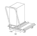
図18は、スタッカトレイ112a,112bおよびドリー120を示す斜視図である。
FIG. 18 is a perspective view showing the
スタッカトレイ112a,112bは昇降可能な不図示の支持部材により支持されており、支持部材がドリー120の支持面よりも下降することによりスタッカトレイ112a,112bはドリー120に受け渡される。図18に示すように、スタッカトレイ112a,112bが、ドリー120の上面に設けられたピン等の固定部材によりドリー120に固定されており、その上に大容量のシート束が積載される。ドリー120には、キャスタ125と把手126とが設けられており、ユーザが把手126をもって移動させることで、大容量のシート束を一度に、しかも簡単に移動させることができる。
The
スタッカトレイ112a,112bを載置されたドリー120がスタッカ装置100から搬出された後、画像形成動作は停止される。ドリー120上のスタッカトレイ112a,112bに積載されたシート束を取除き、再度スタッカトレイ112a,112bおよびドリー120がスタッカ装置100に装着されると、画像形成動作が再開される。なお、予備のドリーおよび2つのスタッカトレイを準備しておき、それらをスタッカ装置100に装着して、画像形成動作を迅速に再開させるようにしてもよい。
After the
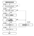
次に、本発明の特徴である積載形態変更処理(シート積載制御方法)について、図19を参照して説明する。 Next, the stacking form changing process (sheet stacking control method) which is a feature of the present invention will be described with reference to FIG.
図19は、図2に示すCPU回路部206において行われる積載形態変更処理の手順を示すフローチャートである。なお、この積載形態変更処理は、図4に示す操作部209の第2の操作画面においてジョブ分割積載モードキー706が選択されているときに、CPU回路部206により実行される。CPU回路部206は、プリントジョブを複数のプリント動作に分割する制御手段(分割工程)としての機能を有する。
Figure 19 is a flowchart showing the procedure of loading form changing processing executed in the
まずステップS101で、CPU回路部206は、プリントジョブの入力を待つ(S101でNO)。プリントジョブが入力されたならば(S101でYES)、ステップS102に進む。
First, in step S101, the
ステップS102では、CPU回路部206は、入力されたプリントジョブにおいてグループモードが指定されているか否かを判別する。グループモードが指定されているならば、ステップS103へ進み、一方、グループモード以外のモード、例えばソートモードが指定されているならば、ステップS107へ進む。
In step S102, the
ステップS107では、CPU回路部206は、積載モードして通常積載モードを設定し、ステップS106に進む。通常積載モードでは、指定されたモードに従ってスタッカトレイへのシートの積載を行う。例えばソートモードが指定されているならば、部単位にシートが積載される。
In step S107, the
ステップS103では、CPU回路部206は、入力されたプリントジョブを解析して、このプリントジョブで印刷を行うべき総プリント枚数(総枚数)を算出する。
In step S103, the
次に、ステップS104では、CPU回路部206は、算出された総プリント枚数が、現在積載を行うべきスタッカトレイにおける積載枚数の上限値(上限積載量)より多いか否かを判定する。なお、この積載枚数の上限値に代わって、最大積載枚数であってもよい。
Next, in step S104, the
この判定の結果、総プリント枚数が積載枚数の上限値よりも多いならば、ステップS105へ進み、総プリント枚数が積載枚数の上限値以下であれば、ステップS107へ進む。 As a result of the determination, if the total number of printed sheets is larger than the upper limit value of the stacked number of sheets , the process proceeds to step S105. If the total number of printed sheets is equal to or less than the upper limit value of the stacked number of sheets, the process proceeds to step S107.
ステップS105では、CPU回路部206は、積載モードしてジョブ分割モードを設定する。このジョブ分割モードについては、後述する。
In step S105, the
ステップS105またはステップS107の実行の後、ステップS106に進み、CPU回路部206は、プリントジョブをスタートする。
After execution of step S105 or step S107, the process proceeds to step S106, where the
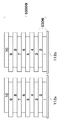
次に、図20および図21を参照して、ジョブ分割モードについて説明する。ジョブ分割モードとは、1部がNページ(Nは整数)のシートを部数M(Mは整数)形成するプリントジョブを、1部がNページのシートをMよりも少ない部数形成する複数のプリントジョブに分割するモードである。分割後の各プリントジョブでは、Mより少ない部数とNとの積が1つのスタッカトレイの上限積載量以下に収まる様になっている。 Next, the job division mode will be described with reference to FIGS. The job division mode refers to a print job in which one copy forms N pages (N is an integer) M copies (M is an integer), and one print forms N pages sheets less than M This mode is divided into jobs. In each divided print job, the product of the number of copies smaller than M and N falls within the upper limit stacking capacity of one stacker tray.
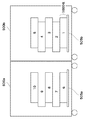
図20は、本発明が適用されず、グループモードにおいてジョブ分割モードが設定されない従来の場合におけるスタッカトレイ112a,112bへのシートの積載状態を示す図である。図21は、グループモードにおいてジョブ分割モードが設定された場合におけるスタッカトレイ112a,112bへのシートの積載状態を示す図である。
FIG. 20 is a diagram showing a stacking state of sheets on the
ここでは例えば、10枚からなる原稿(印刷データ)を1000部、グループモードでプリント(コピーにおけるプリントも含む)するものとする。また、スタッカトレイ112a、112bの積載枚数の上限値がそれぞれ5000枚に設定されているものとする。
Here, for example, it is assumed that 10 originals (print data) are printed in 1000 groups and in group mode (including printing in copying). Further, it is assumed that the upper limit value of the stack number of
更にここでは、図4に示す第2の操作画面において、キー705によって「トレイ2優先」(スタッカトレイ112bに対応)が選択されているものとする。なお、上述の図8〜図18を参照した例では、キー705によって「トレイ1優先」(スタッカトレイ112aに対応)が選択されているものとして説明している。
Furthermore, it is assumed here that “
図20に示すように、本発明が適用されず、ジョブ分割モードの設定がない従来の場合、原稿の第1〜第5ページが1000枚ずつ印刷されて順次スタッカトレイ112bに積載される。これによって、スタッカトレイ112bには上限積載量となる5000枚が積載されるので、次に、スタッカトレイ112aに対して、原稿の第6〜第10ページが1000枚ずつ印刷されて順次積載される。
As shown in FIG. 20, in the conventional case where the present invention is not applied and the job division mode is not set, the first to fifth pages of the document are printed 1000 by 1000 and sequentially stacked on the
ここで、スタッカトレイ112aに対して原稿の第6〜第10ページ分のシートが積載されている間に、満載になったスタッカトレイ112bをスタッカ装置100から外部に運び出して、例えば、不図示の製本装置でコレータ処理を行おうとしたとする。この場合、スタッカトレイ112bには、原稿の第6〜第10ページ分のシートが積載されていないので、こうしたスタック処理の次行程となるコレータ処理を行うことができない。そのため、スタッカトレイ112aに対する原稿の第6〜第10ページのシートの積載を待つ必要があり、作業性が低い。
Here, while the sheets for the sixth to tenth pages of the document are stacked on the
ところが、ジョブ分割モードが設定されると、図21に示すように、スタッカトレイ112a,112bに対するシート積載手順が変更される。すなわち、まず、原稿の第1〜第10ページが500枚ずつ印刷されてスタッカトレイ112bに順次積載される。これによって、スタッカトレイ112bには上限積載量となる5000枚が積載されるので、次に、原稿の第1〜第10ページの残りの各500枚が印刷されてスタッカトレイ112aに順次積載される。
However, when the job division mode is set, the sheet stacking procedure for the
このように、総プリントシート数が一方のスタッカトレイの上限積載量を超えるグループモードのプリントジョブの場合、1グループ当たりのプリント数(同一原稿によるプリント数)が設定された部数よりも少なくなる様にプリントジョブを複数に分割する。そして、一方のスタッカトレイに原稿の全ページをそれぞれ印刷したシートが積載される積載形態に変更する。これによって、スタッカトレイ112aに残りのシートの積載を行っている間に、満載になったスタッカトレイ112bをスタッカ装置100から外部に運び出して、スタック処理の次行程となる、例えばコレータ処理を早く開始させることができる。
As described above, in the case of a print job in a group mode in which the total number of print sheets exceeds the upper limit stacking capacity of one stacker tray, the number of prints per group (the number of prints from the same document) may be smaller than the set number of copies. Divide the print job into multiple parts. Then, the stacking mode is changed so that sheets on which all pages of the document are printed are stacked on one stacker tray. As a result, while the remaining sheets are being stacked on the
なお、上記の実施の形態においては、スタッカ装置100に2つのスタッカトレイ112a,112bが備えられた構成となっているが、これに代わり、スタッカ装置に3つ以上のスタッカトレイが備えられた構成であってもよい。また、画像形成装置900に複数のスタッカ装置が連結される構成であってもよい。
In the above-described embodiment, the
また、上記の実施の形態においては、スタッカ制御部210がスタッカ装置100に設けられているが、これに代わって、スタッカ制御部210を画像形成装置900に設けるようにしてもよい。
In the above-described embodiment, the
また、スタッカ装置100に1つのスタッカトレイが備えられて構成であっても、予備のスタッカトレイがあれば、本発明を適用できる。即ち、スタッカトレイに原稿の第1〜第10ページが500枚ずつ印刷されてスタッカトレイ112bに順次積載される。5000枚のシートが積載されたスタッカトレイを外部の製本装置へ運び、予備のスタッカトレイをスタッカ装置へ設置する。次に原稿の第1〜第10ページの残りの各500枚の印刷を行い、予備のスタッカトレイへ積載を行う。この様にすると、スタック処理の次行程となる、例えばコレータ処理を早く開始させることができる。
Even if the
〔他の実施の形態〕
また、本発明の目的は、以下の処理を実行することによって達成される。即ち、上述した実施の形態の機能を実現するソフトウェアのプログラムコードを記録した記憶媒体を、システム或いは装置に供給し、そのシステム或いは装置のコンピュータ(またはCPUやMPU等)が記憶媒体に格納されたプログラムコードを読み出す処理である。
[Other Embodiments]
The object of the present invention is achieved by executing the following processing. That is, a storage medium storing software program codes for realizing the functions of the above-described embodiments is supplied to a system or apparatus, and a computer (or CPU, MPU, etc.) of the system or apparatus is stored in the storage medium. This is a process of reading the program code.
この場合、記憶媒体から読み出されたプログラムコード自体が前述した実施の形態の機能を実現することになり、そのプログラムコード及び該プログラムコードを記憶した記憶媒体は本発明を構成することになる。 In this case, the program code itself read from the storage medium realizes the functions of the above-described embodiments, and the program code and the storage medium storing the program code constitute the present invention.
また、プログラムコードを供給するための記憶媒体としては、次のものを用いることができる。例えば、フロッピー(登録商標)ディスク、ハードディスク、光磁気ディスク、CD−ROM、CD−R、CD−RW、DVD−ROM、DVD−RAM、DVD−RW、DVD+RW、磁気テープ、不揮発性のメモリカード、ROM等である。または、プログラムコードをネットワークを介してダウンロードしてもよい。 Moreover, the following can be used as a storage medium for supplying the program code. For example, floppy (registered trademark) disk, hard disk, magneto-optical disk, CD-ROM, CD-R, CD-RW, DVD-ROM, DVD-RAM, DVD-RW, DVD + RW, magnetic tape, nonvolatile memory card, ROM or the like. Alternatively, the program code may be downloaded via a network.
また、コンピュータが読み出したプログラムコードを実行することにより、上記実施の形態の機能が実現される場合も本発明に含まれる。加えて、そのプログラムコードの指示に基づき、コンピュータ上で稼動しているOS(オペレーティングシステム)等が実際の処理の一部または全部を行い、その処理によって前述した実施の形態の機能が実現される場合も含まれる。 Further, the present invention includes a case where the function of the above-described embodiment is realized by executing the program code read by the computer. In addition, an OS (operating system) running on the computer performs part or all of the actual processing based on the instruction of the program code, and the functions of the above-described embodiments are realized by the processing. Cases are also included.
更に、前述した実施の形態の機能が以下の処理によって実現される場合も本発明に含まれる。即ち、記憶媒体から読み出されたプログラムコードが、コンピュータに挿入された機能拡張ボードやコンピュータに接続された機能拡張ユニットに備わるメモリに書き込まれる。その後、そのプログラムコードの指示に基づき、その機能拡張ボードや機能拡張ユニットに備わるCPU等が実際の処理の一部または全部を行う場合である。 Furthermore, the present invention includes a case where the functions of the above-described embodiment are realized by the following processing. That is, the program code read from the storage medium is written in a memory provided in a function expansion board inserted into the computer or a function expansion unit connected to the computer. Thereafter, based on the instruction of the program code, the CPU or the like provided in the function expansion board or function expansion unit performs part or all of the actual processing.
100 スタッカ装置
110 排紙ローラ対
112a スタッカトレイ
112b スタッカトレイ
113a,113b ホーム位置検出センサ
114a,114b グリッパ
115 引込みユニット
116 ローレットベルト
120 ドリー
121 先端ストッパ
122 テーパ部
124 排出ローラ対
130 駆動ベルト
205 プリンタ制御部
206 CPU回路部
210 スタッカ制御部
900 画像形成装置
900A 装置本体
906 感光体ドラム
950 自動原稿送り装置
DESCRIPTION OF
Claims (9)
前記画像形成手段によりプリントされたシートを積載するシート積載手段と、
1〜Nページ(Nは整数)の画像をそれぞれM枚(Mは整数)プリントするプリントジョブにおいて、各ページのシートをそれぞれM枚重ねたN個のグループとしてシートを積載するグループモードが設定されている場合に、前記プリントジョブでプリントされるシートの総枚数が前記シート積載手段の上限積載量よりも多ければ、前記プリントジョブを複数のプリント動作に分割する制御手段と、を有し、
前記複数のプリント動作の各々は1〜Nページの画像をそれぞれMよりも少ない枚数プリントする動作であることを特徴とする画像形成装置。 Image forming means for printing an image on a sheet based on the input print job;
Sheet stacking means for stacking sheets printed by the image forming means;
In a print job in which images of 1 to N pages (N is an integer) are printed on each of M sheets (M is an integer), a group mode is set in which sheets are stacked as N groups each of which overlaps M sheets of each page. If it is, if the total number of sheets to be printed by the print job is larger than the upper limit load of the said sheet stacking means, and a control means for dividing the print job into a plurality of printing operations,
Each of the plurality of printing operations is an operation for printing images of 1 to N pages less than M respectively.
前記制御手段は、前記総枚数が、1つのシート積載トレイの上限積載量を超えるならば、前記プリントジョブを分割することを特徴とする請求項1記載の画像形成装置。 Each of the sheet stacking means has a plurality of sheet stacking trays that can be taken out to the outside.
Wherein, the total number is one if the sheet exceeds the upper limit load of the stacking tray, the image forming apparatus according to claim 1, wherein the dividing the print job.
前記画像形成手段によりプリントされたシートを積載するシート積載手段と、
1〜Nページ(Nは整数)の画像をそれぞれM枚(Mは整数)プリントするプリントジョブにおいて、各ページのシートをそれぞれM枚重ねたN個のグループとしてシートを積載するグループモードが設定されている場合に、前記プリントジョブでプリントされるシートの総枚数が前記シート積載手段の上限積載量よりも多ければ、前記プリントジョブにおけるプリント順序を、1〜Nページの画像をそれぞれMよりも少ない枚数プリントする動作を繰り返すように変更する制御手段とを有することを特徴とする画像形成装置。 Image forming means for printing an image on a sheet based on the input print job;
Sheet stacking means for stacking sheets printed by the image forming means;
In a print job in which images of 1 to N pages (N is an integer) are printed on each of M sheets (M is an integer), a group mode is set in which sheets are stacked as N groups each of which overlaps M sheets of each page. If the total number of sheets printed in the print job is larger than the upper limit stacking capacity of the sheet stacking unit, the print order in the print job is less than M for images of 1 to N pages. An image forming apparatus comprising: a control unit configured to change so as to repeat the operation of printing the number of sheets.
1〜Nページ(Nは整数)の画像をそれぞれM枚(Mは整数)プリントするプリントジョブにおいて、各ページのシートをそれぞれM枚重ねたN個のグループとしてシートを積載するグループモードが設定されているか否かを判断する判断工程と、
前記プリントジョブでプリントされるシートの総枚数と前記シート積載手段の上限積載量とを比較する比較工程と、
前記グループモードが設定されている場合に、前記総枚数が前記上限積載量よりも多ければ、前記プリントジョブを複数のプリント動作に分割する分割工程と、を有し、
前記複数のプリント動作の各々は1〜Nページの画像をそれぞれMよりも少ない枚数プリントする動作であることを特徴とするシート積載制御方法。 A sheet stacking control method applied to an image forming apparatus including an image forming unit that prints an image on a sheet based on an input print job, and a sheet stacking unit that stacks sheets printed by the image forming unit. And
In a print job in which images of 1 to N pages (N is an integer) are printed on each of M sheets (M is an integer), a group mode is set in which sheets are stacked as N groups each of which overlaps M sheets of each page. A determination process for determining whether or not
A comparison step of comparing the total number of sheets printed in the print job with the upper limit stacking capacity of the sheet stacking means;
When the group mode has been set, The greater the total number than the upper limit load capacity, has a dividing step of dividing the print job into a plurality of printing operations,
Each of the plurality of printing operations is an operation of printing images of 1 to N pages less than M, respectively.
1〜Nページ(Nは整数)の画像をそれぞれM枚(Mは整数)プリントするプリントジョブにおいて、各ページのシートをそれぞれM枚重ねたN個のグループとしてシートを積載するグループモードが設定されているか否かを判断する判断工程と、
前記プリントジョブでプリントされるシートの総枚数と前記シート積載部の上限積載量とを比較する比較工程と、
前記グループモードが設定されている場合に、前記総枚数が前記上限積載量よりも多ければ、前記プリントジョブにおけるプリント順序を、1〜Nページの画像をMよりも少ない枚数プリントする動作を繰り返すように変更する変更工程と、を有することを特徴とするシート積載制御方法。 A sheet stacking control method applied to an image forming apparatus including an image forming unit that prints an image on a sheet based on an input print job, and a sheet stacking unit that stacks sheets printed by the image forming unit. And
In a print job in which images of 1 to N pages (N is an integer) are printed on each of M sheets (M is an integer), a group mode is set in which sheets are stacked as N groups each of which overlaps M sheets of each page. A determination process for determining whether or not
A comparison step of comparing the total number of sheets printed in the print job with the upper limit stacking capacity of the sheet stacking unit;
When the group mode is set, if the total number of sheets is larger than the upper limit stacking amount, the printing order in the print job is repeated so that the image of 1 to N pages is printed less than M. sheet stacking control method characterized by having a changing step of changing the.
Priority Applications (2)
| Application Number | Priority Date | Filing Date | Title |
|---|---|---|---|
| JP2007122533A JP5072425B2 (en) | 2007-05-07 | 2007-05-07 | Image forming apparatus and sheet stacking control method |
| US12/115,491 US8403325B2 (en) | 2007-05-07 | 2008-05-05 | Image forming apparatus including sheet stacking apparatus |
Applications Claiming Priority (1)
| Application Number | Priority Date | Filing Date | Title |
|---|---|---|---|
| JP2007122533A JP5072425B2 (en) | 2007-05-07 | 2007-05-07 | Image forming apparatus and sheet stacking control method |
Publications (3)
| Publication Number | Publication Date |
|---|---|
| JP2008276120A JP2008276120A (en) | 2008-11-13 |
| JP2008276120A5 JP2008276120A5 (en) | 2010-06-24 |
| JP5072425B2 true JP5072425B2 (en) | 2012-11-14 |
Family
ID=39968808
Family Applications (1)
| Application Number | Title | Priority Date | Filing Date |
|---|---|---|---|
| JP2007122533A Active JP5072425B2 (en) | 2007-05-07 | 2007-05-07 | Image forming apparatus and sheet stacking control method |
Country Status (2)
| Country | Link |
|---|---|
| US (1) | US8403325B2 (en) |
| JP (1) | JP5072425B2 (en) |
Families Citing this family (11)
| Publication number | Priority date | Publication date | Assignee | Title |
|---|---|---|---|---|
| JP2010177789A (en) * | 2009-01-27 | 2010-08-12 | Riso Kagaku Corp | Image copying apparatus |
| JP5606062B2 (en) | 2009-12-26 | 2014-10-15 | キヤノン株式会社 | Printing apparatus, printing apparatus control method, and program |
| JP2011152646A (en) * | 2010-01-26 | 2011-08-11 | Konica Minolta Business Technologies Inc | Apparatus and system for forming image |
| JP2011197240A (en) * | 2010-03-18 | 2011-10-06 | Konica Minolta Business Technologies Inc | Image forming apparatus |
| EP2388651B1 (en) * | 2010-05-17 | 2021-02-24 | Canon Kabushiki Kaisha | Image forming apparatus improved in operability for print job involving single-sided printing and double-sided printing |
| JP5069771B2 (en) * | 2010-05-28 | 2012-11-07 | 京セラドキュメントソリューションズ株式会社 | Paper remaining amount detection device, image forming device |
| JP5472240B2 (en) | 2011-09-16 | 2014-04-16 | コニカミノルタ株式会社 | Image forming apparatus |
| JP5656124B2 (en) * | 2011-12-21 | 2015-01-21 | コニカミノルタ株式会社 | Distributed printing control program, apparatus, and method |
| JP2015001833A (en) * | 2013-06-14 | 2015-01-05 | キヤノン株式会社 | Information processing device and method |
| JP2016161737A (en) * | 2015-03-02 | 2016-09-05 | コニカミノルタ株式会社 | Image formation system |
| JP7286942B2 (en) * | 2018-10-24 | 2023-06-06 | コニカミノルタ株式会社 | Image forming system and program |
Family Cites Families (9)
| Publication number | Priority date | Publication date | Assignee | Title |
|---|---|---|---|---|
| JPH0223164A (en) * | 1988-07-12 | 1990-01-25 | Konica Corp | Paper sheet discharger |
| JP2507680B2 (en) * | 1990-07-02 | 1996-06-12 | 三田工業株式会社 | Sorter control device |
| JP3679498B2 (en) * | 1996-04-04 | 2005-08-03 | 東北リコー株式会社 | Sorting method using sorter mounted image forming apparatus and control device in sorter mounted image forming apparatus |
| JPH1165788A (en) * | 1997-08-27 | 1999-03-09 | Canon Inc | Method for processing printing and device therefor |
| JP2001039607A (en) * | 1999-07-29 | 2001-02-13 | Canon Inc | Image forming device |
| JP3858188B2 (en) * | 2000-07-26 | 2006-12-13 | 株式会社リコー | Image forming apparatus |
| US6481711B1 (en) * | 2000-08-24 | 2002-11-19 | Sharp Laboratories Of America, Inc. | Fast inkjet printer having multiple output trays |
| US7201372B2 (en) * | 2002-02-14 | 2007-04-10 | Bowe Bell + Howell Company | Sheet accumulator systems and methods |
| JP4603333B2 (en) | 2004-10-26 | 2010-12-22 | コニカミノルタビジネステクノロジーズ株式会社 | Paper stacking apparatus and image forming apparatus |
-
2007
- 2007-05-07 JP JP2007122533A patent/JP5072425B2/en active Active
-
2008
- 2008-05-05 US US12/115,491 patent/US8403325B2/en active Active
Also Published As
| Publication number | Publication date |
|---|---|
| US8403325B2 (en) | 2013-03-26 |
| JP2008276120A (en) | 2008-11-13 |
| US20080277866A1 (en) | 2008-11-13 |
Similar Documents
| Publication | Publication Date | Title |
|---|---|---|
| JP5072425B2 (en) | Image forming apparatus and sheet stacking control method | |
| JP4267045B2 (en) | Sheet stacking apparatus and image forming apparatus | |
| JP4747138B2 (en) | Image forming system and image forming apparatus | |
| JP4773776B2 (en) | Sheet stacking apparatus, sheet processing apparatus, and image forming apparatus | |
| JP2001310859A (en) | Sheet after-processing device and image forming device | |
| US8376360B2 (en) | Sheet stacking apparatus and sheet stacking control method | |
| JP4311756B2 (en) | Sheet stacking apparatus and image forming apparatus | |
| JP5213683B2 (en) | Sheet processing apparatus, sheet processing apparatus control method, and program | |
| US8657286B2 (en) | Sheet stacking apparatus and method of controlling the sheet stacking apparatus | |
| JP4307428B2 (en) | Sheet processing apparatus and image forming apparatus | |
| JP4956523B2 (en) | Paper processing apparatus, paper processing method, and image forming apparatus | |
| US8302964B2 (en) | Sheet stacking apparatus and image forming apparatus | |
| JP2019116334A (en) | Sheet discharge device and image forming device | |
| US7766315B2 (en) | Sheet stacking apparatus and method of controlling the sheet stacking apparatus | |
| JP4748820B2 (en) | Sheet stacking apparatus and image forming apparatus | |
| JP2008162753A (en) | Sheet stacking device and image forming device | |
| JP5921237B2 (en) | Sheet stacking device | |
| JP2008120532A (en) | Sheet handling device, image forming device, and loading control method | |
| JP2008056421A (en) | Image forming system and paper delivery method | |
| JP2008179478A (en) | Sheet stacking apparatus and image forming apparatus | |
| JP2009126603A (en) | Sheet stacking device and image forming device | |
| JP2004093984A (en) | Image forming apparatus | |
| JP2004035207A (en) | Supply device for insertion sheet, sheet processing device, and image forming device | |
| JP2010076397A (en) | Image formation system | |
| JP2017026852A (en) | Image forming apparatus and control method of image forming apparatus |
Legal Events
| Date | Code | Title | Description |
|---|---|---|---|
| A521 | Request for written amendment filed |
Free format text: JAPANESE INTERMEDIATE CODE: A523 Effective date: 20100507 |
|
| A621 | Written request for application examination |
Free format text: JAPANESE INTERMEDIATE CODE: A621 Effective date: 20100507 |
|
| A977 | Report on retrieval |
Free format text: JAPANESE INTERMEDIATE CODE: A971007 Effective date: 20120426 |
|
| A131 | Notification of reasons for refusal |
Free format text: JAPANESE INTERMEDIATE CODE: A131 Effective date: 20120508 |
|
| A521 | Request for written amendment filed |
Free format text: JAPANESE INTERMEDIATE CODE: A523 Effective date: 20120705 |
|
| TRDD | Decision of grant or rejection written | ||
| A01 | Written decision to grant a patent or to grant a registration (utility model) |
Free format text: JAPANESE INTERMEDIATE CODE: A01 Effective date: 20120724 |
|
| A01 | Written decision to grant a patent or to grant a registration (utility model) |
Free format text: JAPANESE INTERMEDIATE CODE: A01 |
|
| A61 | First payment of annual fees (during grant procedure) |
Free format text: JAPANESE INTERMEDIATE CODE: A61 Effective date: 20120821 |
|
| R151 | Written notification of patent or utility model registration |
Ref document number: 5072425 Country of ref document: JP Free format text: JAPANESE INTERMEDIATE CODE: R151 |
|
| FPAY | Renewal fee payment (event date is renewal date of database) |
Free format text: PAYMENT UNTIL: 20150831 Year of fee payment: 3 |