JP5070125B2 - Reception device and method, communication system and method, and program - Google Patents
Reception device and method, communication system and method, and programInfo
- Publication number
- JP5070125B2 JP5070125B2 JP2008131274A JP2008131274A JP5070125B2 JP 5070125 B2 JP5070125 B2 JP 5070125B2 JP 2008131274 A JP2008131274 A JP 2008131274A JP 2008131274 A JP2008131274 A JP 2008131274A JP 5070125 B2 JP5070125 B2 JP 5070125B2
- Authority
- JP
- Japan
- Prior art keywords
- size
- fragment
- bit table
- datagram
- bit
- Prior art date
- Legal status (The legal status is an assumption and is not a legal conclusion. Google has not performed a legal analysis and makes no representation as to the accuracy of the status listed.)
- Expired - Fee Related
Links
Images


Classifications
-
- H—ELECTRICITY
- H04—ELECTRIC COMMUNICATION TECHNIQUE
- H04L—TRANSMISSION OF DIGITAL INFORMATION, e.g. TELEGRAPHIC COMMUNICATION
- H04L49/00—Packet switching elements
- H04L49/90—Buffering arrangements
- H04L49/9084—Reactions to storage capacity overflow
- H04L49/9089—Reactions to storage capacity overflow replacing packets in a storage arrangement, e.g. pushout
- H04L49/9094—Arrangements for simultaneous transmit and receive, e.g. simultaneous reading/writing from/to the storage element
-
- H—ELECTRICITY
- H04—ELECTRIC COMMUNICATION TECHNIQUE
- H04L—TRANSMISSION OF DIGITAL INFORMATION, e.g. TELEGRAPHIC COMMUNICATION
- H04L49/00—Packet switching elements
- H04L49/90—Buffering arrangements
Landscapes
- Engineering & Computer Science (AREA)
- Computer Networks & Wireless Communication (AREA)
- Signal Processing (AREA)
- Data Exchanges In Wide-Area Networks (AREA)
- Communication Control (AREA)
Description
本発明は、受信装置及びその方法、通信システム及びその方法、並びに、プログラムに関し、特に、フラグメントされたパケットをビットテーブルを利用してリアセンブルする技術に関する。
The present invention relates to a receiving apparatus and method, a communication system and method, as well, a program, and more particularly to a technique for reassembling fragmented packets using a bit table.
コンピュータネットワークのネットワーク層(インターネット層)においてはインターネット・プロトコル(IP:Internet Protocol)が広く使用されている。そして、インターネット・プロトコルでは、データの送信装置が送信するIPデータグラムをフラグメントと呼ばれる断片にフラグメント(分割)し、受信装置で受信したフラグメントをリアセンブル(組み立て)することが規定されている(非特許文献1)。IPデータグラムのフラグメント/リアセンブルは、通信経路に転送可能なパケットサイズが小さい経路が存在する場合でもサイズの大きなパケットを転送可能にするための処理である。 The Internet protocol (IP) is widely used in the network layer (Internet layer) of computer networks. The Internet protocol stipulates that an IP datagram transmitted by a data transmission apparatus is fragmented (divided) into fragments called fragments, and the fragments received by the reception apparatus are reassembled (non-assembled) (non-assembly). Patent Document 1). Fragment / reassembling of an IP datagram is a process for enabling transfer of a large packet even when there is a route having a small packet size that can be transferred to the communication route.
データを送受信するときにIPデータグラムをフラグメントおよびリアセンブルする場合、受信装置は、どのフラグメントが受信済みで、どのフラグメントが未受信であるかを区別する必要がある。 When fragmenting and reassembling IP datagrams when sending and receiving data, the receiving device needs to distinguish which fragments have been received and which fragments have not been received.
受信済みのフラグメントの区別は、一般に、フラグメントブロックビットテーブル(以下、ビットテーブル)を用いて行われている(非特許文献1)。ビットテーブルは、各ビットがIPデータグラムを構成する各フラグメントに対応づけられたテーブルである。受信装置は、フラグメントの受信に応じて、ビットテーブル中の対応するビットを(例えば、値1に)セットすることで、受信済みのフラグメントと未受信のフラグメントを区別する。 The received fragments are generally distinguished using a fragment block bit table (hereinafter referred to as a bit table) (Non-patent Document 1). The bit table is a table in which each bit is associated with each fragment constituting the IP datagram. In response to the reception of the fragment, the receiving apparatus sets a corresponding bit in the bit table (for example, to a value of 1) to distinguish between a received fragment and an unreceived fragment.
ビットテーブルを利用したリアセンブルを行う場合、データの受信装置は、8192ビットサイズのビットテーブルを確保する必要がある。これは、フラグメント前のIPデータグラムの最大ペイロードサイズが64Kバイトで、フラグメントの最小サイズが8バイトであるということの他に、受信装置は、IPデータグラムとフラグメントのサイズについて事前に知ることができないためである。IPデータグラムのペイロードサイズは64Kバイト以下の範囲の値をとることができ、フラグメントのサイズは8バイト以上の範囲の値をとることができる。つまり、64KバイトのIPデータグラムが8バイト単位でフラグメントされたときに備えて、受信装置は、8192(64Kバイト÷8バイト)ビットサイズのビットテーブルを確保しておく必要があるのである。 When performing reassembly using a bit table, the data receiving apparatus needs to secure a bit table of 8192 bit size. In addition to the fact that the maximum payload size of the IP datagram before fragment is 64 Kbytes and the minimum size of fragment is 8 bytes, the receiving device can know in advance about the size of IP datagram and fragment. This is because it cannot be done. The payload size of the IP datagram can take a value in the range of 64 Kbytes or less, and the fragment size can take a value in the range of 8 bytes or more. That is, in preparation for when a 64 Kbyte IP datagram is fragmented in units of 8 bytes, the receiving apparatus needs to reserve a bit table of 8192 (64 Kbytes / 8 bytes) bit size.
なお、非特許文献1には、フラグメントに関連する情報として、IPデータグラムのヘッダに以下の2フィールドが記載されることが規定されている。
(1)FO(Fragment Offset):フラグメント処理前のIPデータグラムのペイロードのオフセット。
(2)MF(More Fragment flag):後続のフラグメントパケットが存在するかを示すフラグ。
Note that Non-Patent Document 1 stipulates that the following two fields are described in the header of an IP datagram as information related to a fragment.
(1) FO (Fragment Offset): Offset of payload of IP datagram before fragment processing.
(2) MF (More Fragment flag): A flag indicating whether or not there is a subsequent fragment packet.
フラグメントされた終端のIPデータグラムのIPヘッダのMFはセットされていないが、それ以外のすべてのフラグメントされたIPデータグラムのIPヘッダのMFはセットされていることとなる。したがって、フラグメントされた終端のIPデータグラムを受信しない限り、受信装置は、フラグメント前のIPデータグラムのペイロードサイズを判別できない。よって、受信装置は、IPデータグラムの最大ペイロードサイズである64Kバイトに対応した8192ビットのビットテーブルを予め準備しておかなければならない。 The MF of the IP header of the fragmented terminal IP datagram is not set, but the MF of the IP header of all other fragmented IP datagrams is set. Therefore, the receiving apparatus cannot determine the payload size of the pre-fragmented IP datagram unless it receives the terminal IP datagram that has been fragmented. Therefore, the receiving apparatus must prepare in advance an 8192-bit bit table corresponding to 64 Kbytes which is the maximum payload size of the IP datagram.
また、IPデータグラムの送信装置と受信装置の間には、様々なルータとルータを接続する通信網が存在するが、いずれのルータも、フラグメント対象のIPデータグラムがどのようなサイズにフラグメントされて受信装置に到着するかを知る術はない。よって、受信装置は、8バイト単位でフラグメントされた場合を想定したビットテーブルを準備しておかなければならない。
上記のように、従来の構成では、IPデータグラムのサイズが64Kバイトに満たない場合や、フラグメントのサイズが8バイトを超える場合(例えば、1Kバイト)でも、受信装置は8192ビットサイズ分のビットテーブルを確保しておく必要があった。しかし、このような制約は、IPデータグラムのペイロードサイズが64Kバイトより小さい場合や、各フラグメントのサイズが8バイトよりも大きな値で固定されている場合には、ビットテーブルの領域が無駄に確保されることとなる。 As described above, in the conventional configuration, even when the size of the IP datagram is less than 64 Kbytes, or when the fragment size exceeds 8 bytes (for example, 1 Kbyte), the receiving device has 8192 bit size bits. It was necessary to secure a table. However, such a constraint is that the bit table area is wasted when the payload size of the IP datagram is smaller than 64 Kbytes or when the size of each fragment is fixed to a value larger than 8 bytes. Will be.
特に、組み込みシステム等のメモリサイズが限られているプラットフォームでは、システム全体のパフォーマンス低下や、システム構築時のコストの増加が懸念される。 In particular, in a platform with a limited memory size such as an embedded system, there is a concern that the performance of the entire system may be degraded and the cost for system construction may increase.
また、リアセンブル処理はネットワークプロトコル処理において処理負荷の重い処理として知られているため、ビットテーブル領域は高速だが高価なSRAM等で実装する必要がある。したがって、従来の構成では、無駄になる可能性のあるビットテーブルの領域を確保するために高価なSRAMを無駄に使用する必要があった。 In addition, since reassembling processing is known as processing with heavy processing load in network protocol processing, the bit table area needs to be mounted with high-speed but expensive SRAM or the like. Therefore, in the conventional configuration, it is necessary to wastefully use an expensive SRAM in order to secure a bit table area that may be wasted.
本発明は上記課題に鑑みなされたものであり、フラグメントされたパケットを管理するための回路規模を小型化することを可能にする技術を提供することを目的とする。 The present invention has been made in view of the above problems, and an object of the present invention is to provide a technique capable of reducing the circuit scale for managing fragmented packets.
上記目的を達成するため、本発明による受信装置は以下の構成を備える。即ち、
複数のフラグメントに分割されて送信されたパケットを送信装置から受信する受信装置であって、
前記複数のフラグメントの到着状況を管理するビットテーブルを記憶する記憶手段と、
前記送信装置から送信されたフラグメントのサイズを検出する検出手段と、
前記検出されたフラグメントのサイズに応じたサイズの前記ビットテーブルを記憶する領域を前記記憶手段に確保すると共に、前記ビットテーブルに含まれる1ビットが、前記検出手段により検出したサイズの1つのフラグメントの到着状況を示すように前記ビットテーブルを管理する管理手段と、
を備える。
In order to achieve the above object, a receiving apparatus according to the present invention comprises the following arrangement. That is,
A receiving device that receives a packet transmitted by being divided into a plurality of fragments from a transmitting device,
Storage means for storing a bit table for managing the arrival status of the plurality of fragments;
Detecting means for detecting a size of a fragment transmitted from the transmitting device;
An area for storing the bit table having a size corresponding to the size of the detected fragment is secured in the storage unit, and one bit included in the bit table is included in one fragment of the size detected by the detection unit. Management means for managing the bit table to indicate arrival status;
Is provided.
また、本発明による通信システムは以下の構成を備える。即ち、
パケットを送信する送信装置と、該パケットを受信する受信装置と、を備える通信システムであって、
前記送信装置は、
送信するパケットを所定の分割サイズで複数のフラグメントに分割する分割手段と、
前記分割サイズを前記受信装置へ通知する通知手段と、
分割した前記複数のフラグメントを前記受信装置へ順次送信する送信手段と、
を備え、
前記受信装置は、
前記複数のフラグメントの到着状況を管理するビットテーブルを記憶する記憶手段と、
前記送信装置から送信されたフラグメントのサイズを検出する検出手段と、
前記検出されたフラグメントのサイズに応じたサイズの前記ビットテーブルを記憶する領域を前記記憶手段に確保すると共に、前記ビットテーブルに含まれる1ビットが、前記検出手段により検出したサイズの1つのフラグメントの到着状況を示すように前記ビットテーブルを管理する管理手段と、
を備える。
The communication system according to the present invention has the following configuration. That is,
A communication system comprising: a transmission device that transmits a packet; and a reception device that receives the packet,
The transmitter is
Division means for dividing a packet to be transmitted into a plurality of fragments with a predetermined division size;
A notification means for notifying the receiving apparatus of the division size;
Transmitting means for sequentially transmitting the plurality of divided fragments to the receiving device;
With
The receiving device is:
Storage means for storing a bit table for managing the arrival status of the plurality of fragments;
Detecting means for detecting a size of a fragment transmitted from the transmitting device;
An area for storing the bit table having a size corresponding to the size of the detected fragment is secured in the storage unit, and one bit included in the bit table is included in one fragment of the size detected by the detection unit. Management means for managing the bit table to indicate arrival status;
Is provided.
本発明によれば、フラグメントされたパケットを管理するための回路規模を小型化することを可能にする技術を提供することができる。 ADVANTAGE OF THE INVENTION According to this invention, the technique which makes it possible to reduce the circuit scale for managing the fragmented packet can be provided.
以下、添付図面を参照して本発明に係る実施の形態を詳細に説明する。ただし、この実施の形態に記載されている構成要素はあくまでも例示であり、本発明の範囲をそれらのみに限定する趣旨のものではない。また、本実施の形態で説明されている特徴の組み合わせの全てが発明の解決手段に必須のものとは限らない。 Embodiments according to the present invention will be described below in detail with reference to the accompanying drawings. However, the constituent elements described in this embodiment are merely examples, and are not intended to limit the scope of the present invention only to them. In addition, not all the combinations of features described in the present embodiment are essential for the solving means of the invention.
<<第1実施形態>>
(ネットワークプロトコル処理装置)
図1は、本発明の第1実施形態に係るネットワークプロトコル処理装置100を説明する図である。このネットワークプロトコル処理装置100は、IPデータグラム(パケット)を送信する送信装置と、該IPデータグラムを受信する受信装置とを備える通信システムにおいて、送信装置と受信装置との少なくともいずれかとして動作する。
<< First Embodiment >>
(Network protocol processor)
FIG. 1 is a diagram for explaining a network
図1において、101はCPUであり、TCP/IPに準拠したネットワークプロトコル処理をソフトウェアにより実行して、ネットワークプロトコル処理装置100の動作を制御する。102はROMであり、CPU101が実行するソフトウェアが格納されている。103はRAMであり専らCPU101の実行ワークエリアとして使用される。
In FIG. 1,
104はMAC(Media Access Controller)、105はPHY(PHYsical layer)であり、メディア層以下の通信制御を行う。106はDMAC(Direct Memory Access Controller)であり、TCP/IPネットワークで送受信するデータのRAM103とMAC104間の転送を管轄する。107はバスであり、CPU101、ROM102、RAM103、MAC104、DMAC106を相互接続する。
RAM103は安価なDRAM(オフチップ)で実現される場合が一般的であるが、より高速なオンチップSRAMで実現してもよい。しかし、オンチップSRAMは高価なため、本実施形態で想定しているRAM103に格納するデータ全てを格納可能なサイズ分を搭載するのは難しい可能性もある。このような場合には、安価であるが低速なDRAMと高価であるが高速なオンチップSRAMの組合せで実現してもよい。つまり、頻繁にアクセスするデータやネットワークプロトコル処理性能に大きく影響するデータ等を高速なオンチップSRAMに配置し、その他のデータをDRAMに配置する形態である。本実施形態は、DRAM及びオンチップSRAM、またその他の記憶媒体のいずれで実施されてもよく、全てを包含してRAM103と呼ぶ。
The
ところで、RAM103は、CPUの実行ワークエリアとして使用されるだけでなく、TCP/IPネットワークプロトコル処理を実行するために必要となるデータの格納領域としても使用される。当該データには、TCP/IPネットワーク通信において送受信するデータ、後述するビットテーブル、及び当該ビットテーブル管理情報のテーブル等が含まれる。以下、管理情報のテーブルを管理テーブルと呼ぶ。また、管理テーブルに格納される各ビットテーブルの管理情報を管理エントリと呼ぶ。
The
(データ構造)
図2は、RAM103内のデータの構造を模式的に表した図である。図2には本実施形態を説明するために必要なデータのみ示しているため、図示しないがネットワークプロトコル処理を実現するために必要なデータは他にも存在しうる。例えば、CPU101が処理するワークデータ等がそれに該当する。
(data structure)
FIG. 2 is a diagram schematically showing the structure of data in the
図2において、201は送信データ領域であり、送信すべきIPデータグラム(パケット)が格納される。202は受信データ領域であり、受信したIPデータグラムが格納される。203はフラグメントサイズテーブルであり、フラグメントサイズ情報が格納される。204は管理テーブルであり、ビットテーブルの管理情報である管理エントリが格納される。管理エントリは、関連付けられたビットテーブルとともに、主にリアセンブル処理の開始時に生成され、リアセンブル処理終了まで、リアセンブル処理対象のIPデータグラムの情報を保持する。
In FIG. 2,
205はビットテーブル領域であり、ビットテーブル本体が格納される。全てのビットテーブルは、所定の管理エントリに1対1で関連付けられている。206はリアセンブルバッファであり、リアセンブル処理中のIPデータグラムのペイロードデータが格納される。
ここで、リアセンブルバッファ206には、リアセンブル処理中のIPデータグラムのペイロードデータが格納されるが、その格納方法にはさまざまな選択肢がある。リアセンブル処理中のペイロードデータはフラグメントされているが、フラグメント前のペイロードデータに対して先頭から順番に到着する訳ではない。また、既に到着している部分に重複したペイロードデータが後から到着することも考えられる。そのため、一般的な格納方法としては、フラグメント前の最大ペイロードデータサイズである64KB分のデータ領域をリアセンブル処理開始時に確保し、受信したIPデータグラムのペイロードデータを適宜対応する部分に格納していくという手法がある。 Here, the reassembly buffer 206 stores the payload data of the IP datagram being reassembled, and there are various options for the storage method. Although the payload data being reassembled is fragmented, the payload data before fragmentation does not arrive in order from the beginning. It is also conceivable that duplicate payload data arrives later in a portion that has already arrived. Therefore, as a general storage method, a data area of 64 KB, which is the maximum payload data size before fragmentation, is secured at the start of the reassembling process, and the payload data of the received IP datagram is stored in the corresponding part as appropriate. There is a method of going.
また他の方法として、リンクリストを活用する方法もある。これは、細切れで格納されているデータに対し、所定のデータの後に続くデータの格納場所を示すリンク情報を別途管理することで、仮想的に一続きのデータに見せるという手法である。この手法のメリットは、予め64KBという大きいデータ領域を確保することなく、到着したIPデータグラムを順番に関係なく空いている領域に格納していけばよいということである。こうすることで、例えばフラグメント前のペイロードサイズが1KBであった場合などは、64KBものデータ領域を確保する必要が無く、メモリ領域を有効に活用できる。 Another method is to use a linked list. This is a technique in which link data indicating a storage location of data that follows predetermined data is separately managed for data stored in pieces, so that the data is virtually displayed as one continuous data. The merit of this method is that it is sufficient to store the arrived IP datagram in an empty area regardless of the order without securing a large data area of 64 KB in advance. In this way, for example, when the payload size before fragmentation is 1 KB, it is not necessary to secure a data area of 64 KB, and the memory area can be used effectively.
前者の方法は主にハードウェアでリアセンブル処理を行う場合に用いられ、ソフトウェアでリアセンブル処理を行う場合は後者の手法が用いられることが一般的である。リアセンブルバッファの管理は、上記いずれの方法でも、また他の方法でも、最終的にフラグメント前のペイロードデータを再合成可能な方法であればどのようなものでもよい。 The former method is mainly used when the reassembly process is performed by hardware, and the latter method is generally used when the reassembly process is performed by software. The reassembly buffer can be managed by any of the above methods or any other method as long as it can finally re-synthesize the payload data before the fragment.
なお、送信データ領域201はネットワークプロトコル処理装置100が送信装置として動作するときに主に使用される。そして、受信データ領域202、フラグメントサイズテーブル203、管理テーブル204、ビットテーブル領域205、リアセンブルバッファ206は、受信装置として動作するときに主に使用される。
The
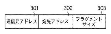
次に、図3、図4及び図5を用いて、フラグメントサイズテーブル203内のフラグメントサイズ情報、管理テーブル204内の管理エントリと、ビットテーブル領域205内のビットテーブルの関係について説明する。図3はフラグメントサイズテーブル203に格納されているフラグメントサイズ情報を詳細に示した図である。図4は管理テーブル204に格納されている管理エントリを詳細に示した図である。一方、図5はビットテーブル領域205に格納されているビットテーブルを詳細に示した図である。
Next, the relationship between the fragment size information in the fragment size table 203, the management entry in the management table 204, and the bit table in the
◆フラグメントサイズ情報
図3において、301は送信元アドレスであり、これはIPヘッダに格納されている送信元アドレス(Source Address)フィールドの値に一致する。302は宛先アドレスであり、同じくIPヘッダの宛先アドレス(Destination Address)フィールドの値に一致する。303はフラグメントサイズであり、IPヘッダ内IPオプションに設定されたフラグメントサイズの値に一致する。フラグメントサイズ303はリアセンブル処理に使用するビットテーブルの単位サイズであり、ビットテーブルの1ビットが何バイトに対応するかを示している。
Fragment Size Information In FIG. 3,
◆管理エントリ
図4において、401は送信元アドレスであり、これはIPヘッダに格納されている送信元アドレス(Source Address)フィールドの値に一致する。402は宛先アドレスであり、同じくIPヘッダの宛先アドレス(Destination Address)に一致する。403は識別子であり、同じくIPヘッダの識別子(Identification)に一致する。送信元アドレス401、宛先アドレス402、及び識別子403はリアセンブル処理対象のIPデータグラム(パケット)を特定するために使用される。404はビットテーブルポインタであり、当該管理エントリに関連付けられているビットテーブルのRAM103内の格納アドレスを示している。
Management entry In FIG. 4, 401 is a source address, which matches the value of the source address field stored in the IP header.
◆ビットテーブル
図5において、501は初期化時のビットテーブル本体を示しており、502は所定のリアセンブル処理中のビットテーブル本体を示している。ビットテーブルの各ビット(501-1〜501-5、502-1〜502-5等)はペイロードが受信済みか否かを示しており、”1”がセットされている場合は受信済みを示している。逆に、”0”がセットされている場合は未受信であることを示している。ビットテーブル初期化時は、全てのペイロードデータが未受信であるため、全ビットが”0”にセットされている。
Bit table In FIG. 5,
ここで例を挙げてフラグメントサイズ303とビットテーブルの関係を説明する。所定のフラグメントサイズ情報のフラグメントサイズ303が1KB(=1024バイト)であったとする。また、当該フラグメントサイズ情報の送信元アドレス301と宛先アドレス302が送信元アドレス401と宛先アドレス402と一致する管理エントリに関連付けられたビットテーブルが、図5における502の状態であったとする。ここで、このビットテーブルは、ビットテーブルポインタ404が示す格納先アドレスビットテーブルに相当する。
Here, the relationship between the
このとき、ビット502-1、502-2、502-3、502-4、502-5は、それぞれ1KB分のペイロードデータに対応する。よって、ビット502-1に”1”がセットされているのは、フラグメント前のIPデータグラムのペイロードの内、先頭から1KBのデータが既に受信されていることを示している。同じように、ビット502-4に”1”がセットされているのは、先頭からのオフセット3KBからの1KB分のデータが既に受信されていることを示す。逆に、”0”がセットされているビット502-2、502-3、502-5は該当部分の1KB分のデータはまだ受信されていないことを示す。
このようにして、ビットテーブルは、送信装置から通知されたフラグメントのサイズ毎に、フラグメントの到着状況を管理する。
At this time, the bits 502-1, 502-2, 502-3, 502-4, and 502-5 correspond to 1 KB worth of payload data, respectively. Therefore, “1” is set in the bit 502-1 indicates that 1 KB of data from the head of the payload of the IP datagram before the fragment has already been received. Similarly, “1” being set in the bit 502-4 indicates that data of 1 KB from the offset 3 KB from the head has already been received. On the other hand, bits 502-2, 502-3, and 502-5 in which “0” is set indicate that 1 KB data of the corresponding part has not been received yet.
In this way, the bit table manages the arrival status of fragments for each fragment size notified from the transmission device.
(MTU探索処理)
本実施形態では、送信装置が、フラグメントのサイズが埋め込まれた判定用データグラムを送信して、受信装置までの通信経路についてMTU(Maximum Transmission Unit)探索を行う。そして、受信装置から受信した受信確認に対応する判定用データグラムに埋め込まれたフラグメントサイズでIPデータグラムをフラグメントに分割し、各フラグメントを受信装置へ順次送信する。ここで、後述するように、受信装置は、MTU探索の処理の途中で、フラグメントのサイズに等しいMTUを知ることができる。このように、本実施形態では、受信装置は、IPデータグラムのフラグメントを受信する前にフラグメントのサイズを知ることができるため、そのフラグメントのサイズに応じて必要最小限のサイズのビットテーブルを確保することができる。
(MTU search process)
In the present embodiment, the transmission device transmits a determination datagram in which the fragment size is embedded, and performs an MTU (Maximum Transmission Unit) search for the communication path to the reception device. Then, the IP datagram is divided into fragments with the fragment size embedded in the determination datagram corresponding to the reception confirmation received from the receiving device, and each fragment is sequentially transmitted to the receiving device. Here, as will be described later, the receiving apparatus can know the MTU equal to the fragment size during the MTU search process. Thus, in this embodiment, since the receiving apparatus can know the size of the fragment before receiving the fragment of the IP datagram, a bit table having a minimum necessary size is secured according to the size of the fragment. can do.
そこで、本実施形態における処理の前提となるMTU探索処理について説明する。ネットワーク層の通信プロトコルにIPを用いるネットワーク通信では、下位層のデータリンク層における最大転送単位(MTU)がそのデータリンク層に用いられる通信プロトコルに応じで決まっている。そのため、送信装置は、IPは送信すべきデータを下位層のMTU以下に分割するフラグメント処理して送信する必要がある。このフラグメント処理を実行するためには大きな負荷がかかるため、他の通信パケットに対する処理に支障が出る場合もある。よって、通信経路の途中でのフラグメント処理を不要にするために、送信装置は、受信装置までの通信経路におけるMTU(以下、「パスMTU」)を予め探索し、探索したパスMTU以下送信すべきデータをフラグメント処理する。なお、IPv4のパスMTUについてはRFC1191に規定されている。このパスMTUの探索はパスMTU探索と呼ばれる。 Therefore, the MTU search process that is the premise of the process in the present embodiment will be described. In network communication using IP as the network layer communication protocol, the maximum transfer unit (MTU) in the lower data link layer is determined according to the communication protocol used in the data link layer. Therefore, it is necessary for the transmitting apparatus to transmit the IP by performing fragment processing for dividing the data to be transmitted into the lower layer MTU or lower. Since a large load is applied to execute this fragment processing, processing for other communication packets may be hindered. Therefore, in order to eliminate the need for fragment processing in the middle of the communication path, the transmitting apparatus should search in advance for the MTU (hereinafter referred to as “path MTU”) in the communication path to the receiving apparatus, and transmit the searched path MTU or less. Fragment data. The IPv4 path MTU is defined in RFC 1191. This path MTU search is called path MTU search.
パスMTU探索では、まず、送信元の装置は最初にサイズの大きなIPデータグラムの分割禁止フラグを立て送信する。これを受信したルータ装置では、次の中継先の経路におけるMTUを参照し、フラグメント処理の実行が必要であるか判断する。フラグメント処理の実行が必要である場合、分割禁止フラグが立っているため、ルータ装置は受信したIPデータグラムを破棄し、ICMP(Internet Control Message Protocol)の到達不能メッセージを送信装置に返信する。この到達不能メッセージには、次の中継先の経路におけるMTUが格納されており、この到達不能メッセージを受信した送信元の装置は、この到達不能メッセージによって通知されたMTU以下にフラグメント処理を行い送信する。送信元の装置は、これを送信先の装置にIPデータグラムが届くまで繰り返すことによって、パスMTUを探索する。 In the path MTU search, first, the transmission source device first sets and transmits a fragmentation prohibition flag for a large IP datagram. The router device that has received this refers to the MTU in the next relay destination route, and determines whether it is necessary to execute fragment processing. When it is necessary to execute fragment processing, since the fragmentation prohibition flag is set, the router device discards the received IP datagram and returns an ICMP (Internet Control Message Protocol) unreachable message to the transmission device. This unreachable message stores the MTU in the route of the next relay destination, and the transmission source device that has received this unreachable message performs fragment processing below the MTU notified by this unreachable message and transmits it. To do. The transmission source device searches for a path MTU by repeating this until an IP datagram reaches the transmission destination device.
具体的には、例えば、送信したICMPechoに対応するICMPreplyの受信可否に基づいてパスMTUを調査することが知られている(例えば、特開2003−18216号公報)。ここでは、DF(分割禁止)フラグを設定したICMPechoをIPパケットサイズを変えながら送信し、このICMPechoに対応するICMPreplyを受信装置から受信できたかに基づいてパスMTUを調査する。 Specifically, for example, it is known to check the path MTU based on whether or not ICMP reply corresponding to the transmitted ICMP echo is received (for example, JP 2003-18216 A). Here, ICMP echo with the DF (division prohibited) flag set is transmitted while changing the IP packet size, and the path MTU is examined based on whether ICMP reply corresponding to this ICMP echo has been received from the receiving device.
(送信処理)
続いて、図1の第1実施形態におけるネットワークプロトコル処理装置100の動作について説明する。まず送信装置として動作する場合の動作について図6を用いて説明する。図6は送信処理の手順を示すフローチャートである。
(Transmission process)
Next, the operation of the network
ネットワークプロトコル処理装置100のCPU101はコネクション確立後、ステップS601においてパスMTU探索を行う。すなわち、受信装置までの通信経路の最大転送単位(MTU)を判定する判定処理を実行する。MTUの判定では、まず、分割禁止フラグがセットされたIPデータグラムを判定用データグラムとして受信装置へ送信する。そして、この判定用データグラムに対応する到達確認データグラムを受信装置から受信するまで、よりサイズの小さい判定用データグラムを受信装置へ送信する処理を繰り返す。受信装置からの到達確認データグラムを受信したら、当該到達確認データグラムに対応する判定用データグラムのサイズをMTUと判定する。
After establishing the connection, the
具体的には、例えば、DF(分割禁止)フラグを設定したICMPechoを、IPデータグラムサイズを変えながら送信する。そして、ICMPechoに対応する送信先の装置(受信装置)からのICMPreplyを送信元の装置で受信できるかを判定することによりパスMTUを調査する。IPデータグラムサイズの初期値は送信元の装置におけるMTU値となり、ICMP到達不能メッセージを受信する毎に、ICMP到達不能メッセージ内に格納されたMTU値を更新する。受信装置からICMPreplyを受信したら、送信装置は、それ以降はそのICMPreplyに対応するICMPechoのサイズをフラグメントのサイズと決定する。 Specifically, for example, ICMP echo in which a DF (division prohibition) flag is set is transmitted while changing the IP datagram size. Then, the path MTU is investigated by determining whether ICMP reply from the transmission destination device (reception device) corresponding to ICMP echo can be received by the transmission source device. The initial value of the IP datagram size is the MTU value in the transmission source device, and the MTU value stored in the ICMP unreachable message is updated each time an ICMP unreachable message is received. When receiving ICMP reply from the receiving apparatus, the transmitting apparatus thereafter determines the ICMP echo size corresponding to the ICMP reply as the fragment size.
CPU101はパスMTU探索を行うIPデータグラム(パケット)のIPヘッダのIPオプションに以下の値をセットする。
・パスMTU探索を行うIPデータグラムであることを示すパスMTU探索識別子(1バイト)
・当該パスMTU探索IPデータグラムによりパスMTUが判明した場合に、以後に送信されるIPデータグラムを何バイトでフラグメントするかを示すフラグメント(分割)サイズ(2バイト)。
ここで、フラグメントサイズは以下のように決定される。
・(IPデータグラムサイズ−20バイト)以下、かつ、8バイトで割り切れる数。
これにより、送信先の装置(受信装置)はパスMTU探索識別子が設定されたICMPechoを受信すると、以後のIPデータグラムが何バイトでフラグメントされるかを予め知ることができる。つまり、本実施形態では、送信装置は、パスMTU探索識別子と共に分割サイズがセットされたIPデータグラムを判定用データグラムとして受信装置へ送信することで、IPデータグラムの分割サイズを受信装置へ通知する通知処理を行っている。
The
-Path MTU search identifier (1 byte) indicating that the IP datagram is to be searched for path MTU.
A fragment (division) size (2 bytes) indicating how many bytes of an IP datagram to be transmitted after that when the path MTU is found from the path MTU search IP datagram.
Here, the fragment size is determined as follows.
-(IP datagram size-20 bytes) or less and a number divisible by 8 bytes.
Thus, when the destination device (receiving device) receives ICMP echo in which the path MTU search identifier is set, it can know in advance how many bytes the subsequent IP datagram is fragmented. In other words, in the present embodiment, the transmission device transmits the IP datagram in which the division size is set together with the path MTU search identifier to the reception device as a determination datagram, thereby notifying the reception device of the division size of the IP datagram. Notification processing is performed.
ステップS602において、CPU101はRAM103の送信データ領域201上に送信すべきデータが存在するかを判定する。ステップS602で送信すべきデータが存在した場合(ステップS602でYES)はステップS603へ進み、存在しない場合(ステップS602でNO)はそのまま待機する。
In step S <b> 602, the
ステップS603ではステップS601で送信先の装置に到着したICMPechoに設定したフラグメントサイズとRAM103の送信データ領域201上の送信すべきデータのサイズを比較する。ステップS603で送信すべきデータのサイズがフラグメントサイズ以上であると判定された場合(ステップS603でYES)はステップS604へ進み、そうでないと判定された場合(ステップS603でNO)はステップS606へ進む。
In step S603, the fragment size set in ICMP echo that has arrived at the transmission destination device in step S601 is compared with the size of data to be transmitted in the
ステップS604では、CPU101は送信すべきデータを、ステップS601で決定したフラグメントサイズ単位にフラグメント(分割)する処理を実行する。すなわち、ステップS601で決定した分割サイズで、送信するIPデータグラムを複数のフラグメントに分割する。次に、ステップS605でフラグメントされたデータに対してIPヘッダを作成し、IPデータグラムを生成する。そして、ステップS607へ進む。
In step S604, the
一方、ステップS603で送信すべきデータがフラグメントサイズより小さいと判定された場合(ステップS603でNO)、ステップS606で送信すべきデータに対してIPヘッダを作成し、IPデータグラムを生成する。そして、ステップS607へ進む。 On the other hand, if it is determined in step S603 that the data to be transmitted is smaller than the fragment size (NO in step S603), an IP header is created for the data to be transmitted in step S606, and an IP datagram is generated. Then, the process proceeds to step S607.
ステップS607においては、CPU101はDMAC106を起動し、DMAC106はRAM103上のフラグメントされたIPデータグラムをMAC104、PHY105へ転送し、IPデータグラムをネットワークへ送信する。すなわち、分割した複数のフラグメントを受信装置へ順次送信する。ステップS607にてDMAC106を起動後、CPU101はステップS602に戻り、RAM103の送信データ領域201上に送信すべきデータが存在するかを判定し、送信すべきデータが存在する場合は前述した処理を繰り返す。
In step S607, the
(受信処理)
次に受信装置として動作する場合の動作について図7を用いて説明する。図7は受信処理の手順を示すフローチャートである。
(Reception processing)
Next, the operation when operating as a receiving apparatus will be described with reference to FIG. FIG. 7 is a flowchart showing the procedure of the reception process.
受信装置は、送信装置から送信された、IPデータグラム(パケット)の複数のフラグメント等を受信する。MAC104、PHY105がIPデータグラムを受信すると割り込み信号をCPU101へ通知する。割り込みを通知されたCPU101はDMAC106を起動し、受信したIPデータグラムをMAC104、PHY105からRAM103の受信データ領域202へ転送させる。RAM103上の受信データ領域202に処理すべきIPデータグラムが存在する場合に、図7のフローチャートに従って受信処理を行う。
The receiving device receives a plurality of fragments of the IP datagram (packet) transmitted from the transmitting device. When the
ステップS701ではIPヘッダの解析を行う。ステップS702では、解析結果を基に、IPデータグラムがフラグメントされているかを判定する。フラグメントされているか否かは、IPヘッダにおけるMFフラグ及びフラグメントオフセットフィールドにより判定する。ステップS702において、IPデータグラムがフラグメントされていると判定された場合(ステップS702でYES)はステップS703へ進み、そうでない場合(ステップS702でNO)はステップS709へ進む。 In step S701, the IP header is analyzed. In step S702, it is determined whether the IP datagram is fragmented based on the analysis result. Whether it is fragmented or not is determined by the MF flag and the fragment offset field in the IP header. If it is determined in step S702 that the IP datagram is fragmented (YES in step S702), the process proceeds to step S703. If not (NO in step S702), the process proceeds to step S709.
なお、上述のように、本実施形態では、送信装置は、MTU探索の後に送信するIPデータグラムのフラグメント/送信を開始する。ここで、パスMTU探索識別子がセットされたIPデータグラムは分割禁止のフラグがセットされている。したがって、受信装置は、MTU探索のためのIPデータグラムを受信すると、まずはステップS709へ移行することになる。後述のように、受信装置は、MTU探索のためのIPデータグラムにセットされているフラグメントサイズを元にフラグメントのサイズを判定し、送信元アドレス、宛先アドレス、フラグメントサイズ等をフラグメントサイズ情報に登録する(ステップS710)。送信装置から通知されたフラグメントのサイズは、MAC、PHY106により受信される。
As described above, in this embodiment, the transmission apparatus starts fragment / transmission of an IP datagram to be transmitted after the MTU search. Here, the division prohibition flag is set in the IP datagram in which the path MTU search identifier is set. Therefore, when the receiving apparatus receives an IP datagram for searching for an MTU, it first proceeds to step S709. As will be described later, the receiving device determines the fragment size based on the fragment size set in the IP datagram for MTU search, and registers the source address, destination address, fragment size, etc. in the fragment size information. (Step S710). The fragment size notified from the transmission apparatus is received by the MAC and
ステップS703では管理テーブル204を検索し、受信したIPデータグラムのIPヘッダに合致する管理エントリが存在するかを確認する。管理エントリがIPヘッダに合致するか否かの判定は、前述したIPヘッダ内の送信元アドレス、宛先アドレス、及び識別子が、それぞれ管理エントリの送信元アドレス401、宛先アドレス402、及び識別子403と一致するかを判定する。
In step S703, the management table 204 is searched to check whether there is a management entry that matches the IP header of the received IP datagram. Whether the management entry matches the IP header is determined by checking that the source address, destination address, and identifier in the IP header described above match the
上記3項目が一致する管理エントリが存在しない場合、受信したIPデータグラムに対するリアセンブル処理はまだ開始されていない、つまり、当該IPヘッダを持つIPデータグラムのリアセンブル処理を開始する必要があることを意味する。そのため、管理エントリがIPヘッダに合致しない場合(ステップS703でNO)は、ステップS704で、リアセンブル初期化処理を実行する。 If there is no management entry that matches the above three items, the reassembling process for the received IP datagram has not started yet, that is, it is necessary to start the reassembling process for the IP datagram having the IP header. Means. Therefore, if the management entry does not match the IP header (NO in step S703), reassembly initialization processing is executed in step S704.
リアセンブル初期化処理において、受信装置は、送信装置から分割サイズが通知されたことに応じて、フラグメントの到着状況を管理するためのビットテーブルを該分割サイズに基づいてメモリに確保する。後述するように、このビットマップテーブルを用いて、送信装置から通知された分割サイズ毎にフラグメントの到着状況を管理する。そして、CPU101は管理テーブル204に対し、新規の管理エントリを作成し、作成した管理エントリの送信元アドレス401、宛先アドレス402、及び識別子403にIPヘッダ内の対応するデータを格納する。また、フラグメントサイズテーブル203を検索し、受信したIPデータグラムのIPヘッダに合致するフラグメントサイズ情報が存在するかを確認する。
In the reassembling initialization process, the receiving device secures a bit table for managing the arrival status of fragments in the memory based on the division size in response to the notification of the division size from the transmission device. As will be described later, this bitmap table is used to manage the arrival status of fragments for each division size notified from the transmission apparatus. Then, the
フラグメントサイズ情報がIPヘッダに合致するか否かの判定は、前述したIPヘッダ内の送信元アドレス、宛先アドレスがフラグメントサイズ情報の送信元アドレス301、宛先アドレス302と一致するかを判定して行う。一致した場合は当該フラグメントサイズ情報のフラグメントサイズ303からビットテーブルサイズを取得する。具体的には、IPデータグラムの最大ペイロードサイズ64KBをフラグメントサイズ303で除算することで算出する。
Whether the fragment size information matches the IP header is determined by determining whether the source address and destination address in the IP header described above match the
例えば、フラグメントサイズ303が1KBであるなら算出されるビットテーブルサイズは64(=64KB÷1KB)ビットとなる。合致するフラグメントサイズ情報が存在しない場合、上記除算においてフラグメントサイズ303は8バイトとされる。このビットテーブルサイズを基に、ビットテーブル領域205にビットテーブルを生成し、ビットテーブルを初期化する。ビットテーブルの初期化では、全てのビットを”0”(未受信)にセットする。最後に、作成した管理エントリのビットテーブルポインタ404に生成したビットテーブルの格納先アドレスを設定し、ステップS705へ進む。
For example, if the
一方、ステップS703で受信したIPデータグラムのIPヘッダにおける送信元アドレス、宛先アドレス、及び識別子が一致する管理エントリが存在した場合(ステップS703でYES)は、ステップS704を経由しないでステップS705へ進む。 On the other hand, if there is a management entry that matches the source address, destination address, and identifier in the IP header of the IP datagram received in step S703 (YES in step S703), the process proceeds to step S705 without going through step S704. .
ステップS705では受信したフラグメントについてリアセンブル処理を行う。すなわち、受信したフラグメントの到着状況を、送信装置から通知された分割サイズ毎にビットテーブルで管理する。具体的には、リアセンブル処理では、受信したIPデータグラムのIPヘッダ内の送信元アドレス、宛先アドレスと送信元アドレス301、宛先アドレス302が一致するフラグメントサイズ情報を検索する。そして、当該フラグメントサイズ情報のフラグメントサイズ303を取得する。さらに、取得したフラグメントサイズ303とIPヘッダ内のフラグメントオフセットを基に、ビットテーブルポインタ404の指し示すビットテーブルの対応するビットに”1”を設定する。ここで、受信したIPデータグラムにてMFフラグが”0”であった場合はビットテーブルの対応するビット以降のビットに”1”を設定する。そして、ステップS706へ進む。
In step S705, a reassembly process is performed on the received fragment. That is, the arrival status of the received fragment is managed in the bit table for each division size notified from the transmission device. Specifically, in the reassembling process, fragment size information in which the source address, destination address,
ステップS706では、対象のIPデータグラムについてリアセンブル処理が完了したか否か判定する。具体的には、ビットテーブルの全てのビットが”1”にセットされた場合に全てのフラグメントされたIPデータグラムを受信した、つまりリアセンブル処理が完了したと判定する。なお、リアセンブル処理の完了を判定する具体的な処理手順はこのような手法に限られるわけでなく、他の方法で実現しても良い。すなわち、リアセンブル処理が完了したと明確に判断可能な方法であれば、いずれの実現方法を用いても構わない。 In step S706, it is determined whether the reassembly process has been completed for the target IP datagram. Specifically, when all bits in the bit table are set to “1”, it is determined that all fragmented IP datagrams have been received, that is, the reassembly process has been completed. Note that the specific processing procedure for determining the completion of the reassembly process is not limited to such a method, and may be realized by another method. That is, any realization method may be used as long as it can be clearly determined that the reassembly process is completed.
ステップS706でリアセンブル処理が未完了と判定された場合(ステップS706でNO)は、ステップS701へ戻り、次のIPデータグラムのフラグメントを受信したときに再度処理を開始する。ステップS706でリアセンブル処理を完了したと判定された場合(ステップS706でYES)には、ステップS707へ進む。 If it is determined in step S706 that the reassembly process has not been completed (NO in step S706), the process returns to step S701, and the process is started again when the next IP datagram fragment is received. If it is determined in step S706 that the reassembly process has been completed (YES in step S706), the process proceeds to step S707.
ステップS707では、CPU101は受信したIPデータグラムのIPヘッダ内の送信元アドレス、宛先アドレス、及び識別子と送信元アドレス401、宛先アドレス402、及び識別子403が一致する管理エントリを検索する。そして、当該管理エントリ、及び当該管理エントリ内のビットテーブルポインタ404の指し示すビットテーブルを解放する。
In step S707, the
その後、ステップS708ではリアセンブル処理の完了したペイロードデータを上位層へ受け渡す。そして処理を終了する。 Thereafter, in step S708, the payload data for which the reassembly process has been completed is transferred to the upper layer. Then, the process ends.
一方、ステップS702において、フラグメントされていないと判定された(ステップS702でNO)IPデータグラムについては、ステップS709においてIPヘッダ内のIPオプションにパスMTU探索識別子がセットされているか判定する。パスMTU探索識別子がセットされている場合(ステップS709でYES)はステップS710へ進む。 On the other hand, for an IP datagram determined not to be fragmented in step S702 (NO in step S702), it is determined in step S709 whether a path MTU search identifier is set in the IP option in the IP header. If the path MTU search identifier is set (YES in step S709), the process advances to step S710.
ステップS710では、CPU101はフラグメントサイズ登録処理を実行する。フラグメントサイズ登録処理において、CPU101はフラグメントサイズテーブル203に対し、IPヘッダ内の送信元アドレス、宛先アドレスがフラグメントサイズ情報の送信元アドレス301、宛先アドレス302と一致するかを判定する。一致した場合は当該フラグメントサイズ情報のフラグメントサイズ303をIPヘッダ内のIPオプションに設定されたフラグメントサイズで更新する。一致するフラグメントサイズ情報がない場合、CPU101は新規のフラグメントサイズ情報を作成し、作成したフラグメントサイズ情報の送信元アドレス301、宛先アドレス302、フラグメントサイズ303にIPヘッダ内の対応するデータを格納する。そして、ステップS708へ進む。
In step S710, the
一方、ステップS709において、パスMTU探索識別子がセットされていない場合(ステップS709でNO)、ステップS708へ進み、IPデータグラムのペイロードデータを上位層へ受け渡す。上位層は、通常は、TCP処理を行うソフトウェアにより実現されるが、ハードウェアで実現しても構わない。 On the other hand, if the path MTU search identifier is not set in step S709 (NO in step S709), the process proceeds to step S708, and the payload data of the IP datagram is transferred to the upper layer. The upper layer is usually realized by software that performs TCP processing, but may be realized by hardware.
上記のように、本実施形態において受信装置は、送信装置から分割サイズが通知されたことに応じて、フラグメントの到着状況を管理するためのビットテーブルを該分割サイズに基づいてメモリに確保する。このため、受信装置は、不必要に大きなビットテーブルをメモリに確保せず、メモリを効率的に使用することができ、受信装置で確保が必要なビットテーブルのサイズを小さくすることを可能である。 As described above, in the present embodiment, in response to the notification of the division size from the transmission device, the reception device secures a bit table for managing the arrival status of fragments in the memory based on the division size. For this reason, the receiving apparatus can efficiently use the memory without securing an unnecessarily large bit table in the memory, and the size of the bit table that needs to be secured in the receiving apparatus can be reduced. .
また、本実施形態において受信装置は、パスMTU探索パケットに設定されたフラグメントサイズにより、分割サイズを検出するため、本実施形態は、MTU探索を行う構成において容易に実装することができる。 Further, in the present embodiment, since the receiving apparatus detects the division size based on the fragment size set in the path MTU search packet, the present embodiment can be easily implemented in a configuration that performs MTU search.
以上のようにして、第1実施形態においては、パスMTU探索時にフラグメント処理を行うサイズを送信装置と受信装置間で共有する。これにより、受信装置ではフラグメントされたIPデータグラム(パケット)の到着状況を共有しているサイズ単位で管理することが可能になる。したがって、到着状況を管理するビットテーブルが必要とするサイズを削減することが可能になる。 As described above, in the first embodiment, the size for performing fragment processing when searching for a path MTU is shared between the transmission device and the reception device. As a result, the receiving apparatus can manage the arrival status of the fragmented IP datagram (packet) in units of shared size. Therefore, the size required for the bit table for managing the arrival status can be reduced.
<<第2実施形態>>
第1実施形態では、送信装置は、MTU探索識別子がセットされたパケットにフラグメントのサイズをセットして、フラグメントのサイズを受信装置に通知していた。本実施形態では、送信装置が、IPデータグラム(パケット)の各フラグメントのIPヘッダにフラグメントのサイズを記載して、フラグメントのサイズを受信装置に通知する構成を説明する。
<< Second Embodiment >>
In the first embodiment, the transmission device sets the fragment size in the packet in which the MTU search identifier is set, and notifies the reception device of the fragment size. In the present embodiment, a configuration will be described in which the transmitting device describes the fragment size in the IP header of each fragment of the IP datagram (packet) and notifies the receiving device of the fragment size.
本実施形態に係るネットワークプロトコル処理装置100の構成は、第1実施形態と同様に図1で示されるため説明を省略する。また、受信装置として動作するネットワークプロトコル処理装置100がメモリに確保するビットテーブルの構成は、第1実施形態と同様に図5で示されるため説明を省略する。
Since the configuration of the network
(データ構造)
図8は、本実施形態に係るネットワークプロトコル処理装置100のRAM103内のデータを模式的に表した図である。図8には本実施形態を説明するために必要なデータのみ示しているため、図示しないがネットワークプロトコル処理を実現するために必要なデータは他にも存在する。例えば、CPU101が処理するワークデータ等がそれに該当する。図2と図8を比較して分かるように、本実施形態ではフラグメントサイズテーブルを使用しない。
(data structure)
FIG. 8 is a diagram schematically showing data in the
図8において、801は送信データ領域であり、送信すべきIPデータグラム(パケット)が格納される。802は受信データ領域であり、受信したIPデータグラムが格納される。803は管理テーブルであり、ビットテーブルの管理情報である管理エントリが格納される。管理エントリは、関連付けられたビットテーブルとともに、主にリアセンブル処理の開始時に生成され、リアセンブル処理終了まで、リアセンブル処理対象のIPデータグラムの情報を保持する。
In FIG. 8,
804はビットテーブル領域であり、ビットテーブル本体が格納される。全てのビットテーブルは、所定の管理エントリに1対1で関連付けられている。ビットテーブルは、第1実施形態と同様に図5で示される。805はリアセンブルバッファであり、リアセンブル処理中のIPデータグラムのペイロードデータが格納される。リアセンブルバッファ805については、第1実施形態において説明したため、ここでは省略する。
A
◆管理エントリ
次に、図9を用いて、管理テーブル803内の管理エントリと、ビットテーブル領域804内のビットテーブルの関係について説明する。図9は管理テーブル803に格納されている管理エントリを詳細に示した図である。
Management entry Next, the relationship between the management entry in the management table 803 and the bit table in the
図9において、901は送信元アドレスであり、これはIPヘッダに格納されている送信元アドレス(Source Address)フィールドの値に一致する。902は宛先アドレスであり、同じくIPヘッダの宛先アドレス(Destination Address)に一致する。903は識別子であり、同じくIPヘッダの識別子(Identification)に一致する。
In FIG. 9,
送信元アドレス901、宛先アドレス902、及び識別子903はリアセンブル処理対象のIPデータグラムを特定するために使用される。904はビットテーブル単位サイズであり、関連するビットテーブルの1ビットが何バイトに対応するかを示している。905はビットテーブルポインタであり、当該管理エントリに関連付けられているビットテーブルのRAM103内の格納アドレスを示している。
The
以下例を挙げてビットテーブル単位サイズ904とビットテーブルの関係を説明する。所定の管理エントリのビットテーブル単位サイズ904が1KB(=1024バイト)であったとする。また、当該管理エントリに関連付けられたビットテーブル(ビットテーブルポインタ905が示す格納先アドレスビットテーブル)が、図5における502の状態であったとする。
The relationship between the bit
このとき、ビット502-1、502-2、502-3、502-4、502-5は、それぞれ1KB分のペイロードデータに対応する。よって、ビット502-1に”1”がセットされているのは、フラグメント前のIPデータグラムのペイロードの内、先頭から1KBのデータが既に受信されていることを示している。同じように、ビット502-4に”1”がセットされているのは、先頭からのオフセット3KBからの1KB分のデータが既に受信されていることを示す。一方、”0”がセットされているビット502-2、502-3、502-5は該当部分の1KB分のデータはまだ受信されていないことを示す。 At this time, the bits 502-1, 502-2, 502-3, 502-4, and 502-5 correspond to 1 KB worth of payload data, respectively. Therefore, “1” is set in the bit 502-1 indicates that 1 KB of data from the head of the payload of the IP datagram before the fragment has already been received. Similarly, “1” being set in the bit 502-4 indicates that data of 1 KB from the offset 3 KB from the head has already been received. On the other hand, bits 502-2, 502-3, and 502-5 in which “0” is set indicate that 1 KB data of the corresponding part has not been received yet.
(送信処理)
続いて、送信装置として動作するネットワークプロトコル処理装置100の動作について説明する。本実施形態に係る送信装置の動作は第1実施形態と同様に図6で示される。このため、第1実施形態と共通の動作は説明済みのため省略し、第1実施形態と異なる動作のみを説明する。
(Transmission process)
Next, the operation of the network
CPU101はコネクション確立後、ステップS601においてパスMTU探索を行う。パスMTU探索では、DFフラグを設定したICMPechoを、IPデータグラムサイズを変えながら送信し、ICMPechoに対応する送信先の装置からのICMPreplyを送信元の装置で受信できるかを判定することによりパスMTUを調査する。
After establishing the connection, the
ステップS602では、CPU101はRAM103の送信データ領域201上に送信すべきデータが存在するかを判定する。ステップS602で送信すべきデータが存在した場合、ステップS603ではステップS601で探索したパスMTUサイズからフラグメントサイズを算出する。フラグメントサイズは(パスMTU−24バイト)以下、かつ、8バイトで割り切れる最大数として算出される。そして、算出したフラグメントサイズとRAM103の送信データ領域801上の送信すべきデータのサイズを比較する。
In step S <b> 602, the
ステップS603で送信すべきデータがフラグメントサイズより大きいと判定された場合に、ステップS604でCPU101は送信すべきデータをフラグメントサイズ単位にフラグメント処理を実行する。
If it is determined in step S603 that the data to be transmitted is larger than the fragment size, in step S604, the
そして、ステップS605でフラグメントされたデータに対してIPヘッダを作成し、IPデータグラムを生成する。IPヘッダを生成する際、CPU101はIPオプションにフラグメントサイズ設定フラグ(1バイト)とフラグメントサイズ(2バイト)をセットする。これにより、送信先の装置がこのフラグメントされたIPデータグラムのいずれかを受信すると、以後のIPデータグラムが何バイトでフラグメントされるかを知ることができる。
In step S605, an IP header is created for the fragmented data to generate an IP datagram. When generating the IP header, the
ステップS606とステップS607における処理は第1実施形態と同様である。ステップS607にてDMAC106を起動後、CPU101はステップS602に戻り、RAM103の送信データ領域801上に送信すべきデータが存在するかを判定し、送信すべきデータが存在する場合は前述した処理を繰り返す。
The processes in step S606 and step S607 are the same as in the first embodiment. After starting the
(受信処理)
次に受信装置として動作するネットワークプロトコル処理装置100の動作について説明する。本実施形態に係る受信装置の動作は、第1実施形態における動作と一部が共通する。このため、第1実施形態と異なる動作のみを図7を参照して説明し、第1実施形態と共通の動作は説明済みのため省略する。なお、本実施形態では、ステップS702でNOの場合はステップS708へ進み、ステップS709、ステップS710の処理は行わない。
(Reception processing)
Next, the operation of the network
MAC104、PHY105がIPデータグラム(パケット)を受信すると割り込み信号をCPU101へ通知する。割り込みを通知されたCPU101はDMAC106を起動し、受信したIPデータグラムをMAC104、PHY105からRAM103の受信データ領域802へ転送させる。RAM103上の受信データ領域802に処理すべきIPデータグラムが存在する場合に、図7のフローチャートに従って受信処理を行う。
When the
ステップS701ではIPヘッダの解析を行う。ステップS702では、解析結果を基に、IPデータグラムがフラグメントされているかを判定する。この判定は第1実施形態と同様に行うことができる。 In step S701, the IP header is analyzed. In step S702, it is determined whether the IP datagram is fragmented based on the analysis result. This determination can be performed as in the first embodiment.
ステップS702において、IPデータグラムがフラグメントされていると判定された場合(ステップS702でYES)、ステップS703へ進む。一方、IPデータグラムがフラグメントされていないと判定された場合(ステップS702でNO)、本実施形態では、ステップS708へ進む。本実施形態では、フラグメントのサイズを、MTU探索識別子がセットされたパケットではなく、フラグメントされたパケットのIPヘッダの記載から判定するためである。 If it is determined in step S702 that the IP datagram is fragmented (YES in step S702), the process advances to step S703. On the other hand, if it is determined that the IP datagram is not fragmented (NO in step S702), the process proceeds to step S708 in the present embodiment. This is because in this embodiment, the size of the fragment is determined from the description of the IP header of the fragmented packet, not the packet in which the MTU search identifier is set.
ステップS703の処理は第1実施形態と同様である。続くステップS704で、リアセンブル初期化処理を実行する。リアセンブル初期化処理において、CPU101は管理テーブル803に対し、新規の管理エントリを作成し、作成した管理エントリの送信元アドレス901、宛先アドレス902、及び識別子903にIPヘッダ内の対応するデータを格納する。また、IPヘッダ内IPオプションにフラグメント設定フラグがセットされていた場合、同じくIPヘッダ内IPオプションに設定されているフラグメントサイズを作成した管理エントリのビットテーブル単位サイズ904に格納する。IPヘッダ内オプションにフラグメント設定フラグがセットされていない場合、ビットテーブル単位サイズ904には最小のフラグメントサイズに相当する8(バイト)を格納する。
The process in step S703 is the same as that in the first embodiment. In the subsequent step S704, reassembling initialization processing is executed. In the reassembly initialization process, the
次に、CPU101はビットテーブル単位サイズ904からビットテーブルサイズを取得する。具体的には、IPデータグラムの最大ペイロードサイズ64KBをビットテーブル単位サイズ904で除算して算出する。例えば、ビットテーブル単位サイズ904が1KBであるなら算出されるビットテーブルサイズは64(=64KB÷1KB)となる。このビットテーブルサイズを基に、ビットテーブル領域804にビットテーブルを生成し、ビットテーブルを初期化する。ビットテーブルの初期化は全てのビットを”0”にセットすることで行う。最後に、作成した管理エントリのビットテーブルポインタ905に生成したビットテーブルの格納先アドレスを設定する。そして、ステップS705へ進む。
Next, the
ステップS705ではリアセンブル処理を行う。リアセンブル処理においては、受信したIPデータグラムのIPヘッダ内の送信元アドレス、宛先アドレス、及び識別子と送信元アドレス901、宛先アドレス902、及び識別子903が一致する管理エントリを検索する。そして、当該管理エントリのビットテーブル単位サイズ904とIPヘッダ内のフラグメントオフセットを基に、ビットテーブルポインタ905の指し示すビットテーブルの対応するビットに”1”を設定する。ここで、受信したIPデータグラムにてMFフラグが”0”であった場合はビットテーブルの対応するビット以降のビットに”1”を設定する。そしてステップS706へ進む。
In step S705, a reassembly process is performed. In the reassembling process, a management entry in which the source address, destination address, and identifier in the IP header of the received IP datagram match the
ステップS706〜S708の処理は第1実施形態と同様である。なお、ステップS702において、フラグメントされていないと判定されたIPデータグラムのペイロードデータを上位層へ受け渡す。上位層は通常はTCP処理を行うソフトウェアであるが、本実施形態では特に限定しない。 The processing in steps S706 to S708 is the same as that in the first embodiment. In step S702, the payload data of the IP datagram determined not to be fragmented is transferred to the upper layer. The upper layer is usually software that performs TCP processing, but is not particularly limited in this embodiment.
上記のように、本実施形態では、送信装置は、複数のフラグメントの各々のヘッダに、その分割サイズを示すサイズ情報を格納することで、分割サイズを受信装置へ通知する。そして、受信装置は、受信したフラグメントのヘッダに格納されているサイズ情報により示される分割サイズに基づいて、ビットテーブルをメモリに確保する。このため、本実施形態によれば、受信装置は、通知される分割サイズに基づいて、必要なだけのサイズのビットテーブルを用意すればよく、したがって、受信装置で確保が必要なビットテーブルのサイズを小さくすることを可能である。 As described above, in the present embodiment, the transmission device stores the size information indicating the division size in each header of the plurality of fragments, thereby notifying the reception device of the division size. Then, the receiving apparatus secures the bit table in the memory based on the division size indicated by the size information stored in the header of the received fragment. For this reason, according to the present embodiment, the receiving device only needs to prepare a bit table having a necessary size based on the notified division size, and therefore the size of the bit table that needs to be secured in the receiving device. Can be reduced.
以上のようにして、第2実施形態においては、パスMTU探索後にフラグメント処理を行うサイズを送信装置と受信装置間で共有する。これにより、受信装置ではフラグメントされたIPデータグラム(パケット)の到着状況を共有しているサイズ単位で管理することが可能になる。これにより、到着状況を管理するビットテーブルが必要とするサイズを削減することが可能になる。 As described above, in the second embodiment, the size for performing fragment processing after path MTU search is shared between the transmission device and the reception device. As a result, the receiving apparatus can manage the arrival status of the fragmented IP datagram (packet) in units of shared size. This makes it possible to reduce the size required for the bit table for managing the arrival status.
<<その他の実施形態>>
本発明の目的は、前述した実施形態の機能を実現するソフトウエアのプログラムコードをシステムあるいは装置で実行することによっても達成されることは言うまでもない。この場合、プログラムコード自体が前述した実施形態の機能を実現することとなり、そのプログラムコードは本発明の技術的範囲に含まれる。
<< Other Embodiments >>
It goes without saying that the object of the present invention can also be achieved by executing a program code of software that realizes the functions of the above-described embodiments in a system or apparatus. In this case, the program code itself realizes the functions of the above-described embodiments, and the program code is included in the technical scope of the present invention.
プログラムコードは、例えば、コンピュータ読み取り可能な記録媒体に記録してシステムあるいは装置に供給することができる。そのシステムあるいは装置のコンピュータ(またはCPUまたはMPU)は、記録媒体に格納されたプログラムコードを読み出し実行することによっても、本発明の目的を達成することができる。従って、そのプログラムコードを記憶した記録媒体も本発明の技術的範囲に含まれる。 For example, the program code can be recorded on a computer-readable recording medium and supplied to the system or apparatus. The computer (or CPU or MPU) of the system or apparatus can also achieve the object of the present invention by reading and executing the program code stored in the recording medium. Therefore, the recording medium storing the program code is also included in the technical scope of the present invention.
プログラムコードを供給するための記録媒体としては、例えば、フレキシブルディスク、ハードディスク、光ディスク、光磁気ディスク、CD−ROM、CD−R、磁気テープ、不揮発性のメモリカード、ROM、DVDなどを用いることができる。 As a recording medium for supplying the program code, for example, a flexible disk, a hard disk, an optical disk, a magneto-optical disk, a CD-ROM, a CD-R, a magnetic tape, a nonvolatile memory card, a ROM, a DVD, or the like is used. it can.
なお、プログラムコードは、コンピュータが当該プログラムコードを読み出し実行することにより前述した実施形態の機能を実現するための、全ての要素を備えたものに限られない。即ち、プログラムコードには、コンピュータに組み込まれたソフトウェア及びハードウェアの少なくともいずれかと協働することにより目的を達成するプログラムコードも含まれる。 Note that the program code is not limited to the one having all the elements for realizing the functions of the above-described embodiments by the computer reading and executing the program code. That is, the program code includes a program code that achieves an object by cooperating with at least one of software and hardware incorporated in the computer.
例えば、プログラムコードの指示に基づき、コンピュータ上で稼動しているOSなどが実際の処理の一部または全部を行い、その処理によって前述した実施形態の機能が実現される場合も、そのプログラムコードは本発明の技術的範囲に含まれる。ただし、OSはオペレーティングシステム(Operating System)の略称である。 For example, even when the OS running on the computer performs part or all of the actual processing based on the instruction of the program code and the functions of the above-described embodiments are realized by the processing, the program code is It is included in the technical scope of the present invention. However, OS is an abbreviation for operating system.
あるいは、例えば、プログラムコードの指示に基づき、コンピュータに挿入又は接続された機能拡張ボードや機能拡張ユニットに備わるCPUなどが実際の処理の一部または全部を行い、その処理によって前述した実施形態の機能が実現される場合がある。このような場合も、そのプログラムコードは本発明の技術的範囲に含まれる。なお、機能拡張ボードや機能拡張ユニットは、それらが備えるメモリにプログラムコードを読み込み、実行することでこのような処理を行うことができる。 Alternatively, for example, based on an instruction of a program code, a function expansion board inserted or connected to a computer or a CPU provided in a function expansion unit performs part or all of the actual processing, and the function of the above-described embodiment is performed by the processing. May be realized. Even in such a case, the program code is included in the technical scope of the present invention. Note that the function expansion board and the function expansion unit can perform such processing by reading and executing the program code in the memory provided therein.
以上説明したように、本発明によれば、ネットワークプロトコル処理におけるリアセンブル処理時に、ビットテーブルを8バイト以上の単位サイズで構成することにより、ビットテーブルサイズを縮小することができる。これにより、リアセンブル処理に必要となるメモリ領域を削減することができ、ネットワークプロトコル処理のパフォーマンス低下の抑制、及びシステム構築時のコストを低減することができる。特にメモリ領域が限られている組み込みシステム等では大きな効果が期待できる。 As described above, according to the present invention, the bit table size can be reduced by configuring the bit table with a unit size of 8 bytes or more during the reassembling process in the network protocol process. As a result, it is possible to reduce the memory area required for the reassembly process, to suppress the performance degradation of the network protocol process, and to reduce the cost for constructing the system. In particular, a large effect can be expected in an embedded system having a limited memory area.
Claims (7)
前記複数のフラグメントの到着状況を管理するビットテーブルを記憶する記憶手段と、
前記送信装置から送信されたフラグメントのサイズを検出する検出手段と、
前記検出されたフラグメントのサイズに応じたサイズの前記ビットテーブルを記憶する領域を前記記憶手段に確保すると共に、前記ビットテーブルに含まれる1ビットが、前記検出手段により検出したサイズの1つのフラグメントの到着状況を示すように前記ビットテーブルを管理する管理手段と、
を備えることを特徴とする受信装置。 A receiving device that receives a packet transmitted by being divided into a plurality of fragments from a transmitting device,
Storage means for storing a bit table for managing the arrival status of the plurality of fragments;
Detecting means for detecting a size of a fragment transmitted from the transmitting device;
An area for storing the bit table having a size corresponding to the size of the detected fragment is secured in the storage unit, and one bit included in the bit table is included in one fragment of the size detected by the detection unit. Management means for managing the bit table to indicate arrival status;
A receiving apparatus comprising:
前記送信装置から当該受信装置までの通信経路の最大転送単位を判定するために前記送信装置から送信された、分割サイズがセットされたパケットにより前記送信装置から通知される
ことを特徴とする請求項1に記載の受信装置。 The size of the fragment is
The transmission device is notified by a packet set with a division size transmitted from the transmission device to determine a maximum transfer unit of a communication path from the transmission device to the reception device. The receiving device according to 1.
ことを特徴とする請求項1に記載の受信装置。 The receiving apparatus according to claim 1, wherein the size of the fragment is reported in a header of each fragment.
前記送信装置は、
送信するパケットを所定の分割サイズで複数のフラグメントに分割する分割手段と、
前記分割サイズを前記受信装置へ通知する通知手段と、
分割した前記複数のフラグメントを前記受信装置へ順次送信する送信手段と、
を備え、
前記受信装置は、
前記複数のフラグメントの到着状況を管理するビットテーブルを記憶する記憶手段と、
前記送信装置から送信されたフラグメントのサイズを検出する検出手段と、
前記検出されたフラグメントのサイズに応じたサイズの前記ビットテーブルを記憶する領域を前記記憶手段に確保すると共に、前記ビットテーブルに含まれる1ビットが、前記検出手段により検出したサイズの1つのフラグメントの到着状況を示すように前記ビットテーブルを管理する管理手段と、
を備える
ことを特徴とする通信システム。 A communication system comprising: a transmission device that transmits a packet; and a reception device that receives the packet,
The transmitter is
Division means for dividing a packet to be transmitted into a plurality of fragments with a predetermined division size;
A notification means for notifying the receiving apparatus of the division size;
Transmitting means for sequentially transmitting the plurality of divided fragments to the receiving device;
With
The receiving device is:
Storage means for storing a bit table for managing the arrival status of the plurality of fragments;
Detecting means for detecting a size of a fragment transmitted from the transmitting device;
An area for storing the bit table having a size corresponding to the size of the detected fragment is secured in the storage unit, and one bit included in the bit table is included in one fragment of the size detected by the detection unit. Management means for managing the bit table to indicate arrival status;
A communication system comprising:
前記送信装置から送信されたフラグメントのサイズを検出する検出工程と、
前記検出されたフラグメントのサイズに応じたサイズの前記ビットテーブルを記憶する領域を前記記憶手段に確保すると共に、前記ビットテーブルに含まれる1ビットが、前記検出工程において検出したサイズの1つのフラグメントの到着状況を示すように前記ビットテーブルを管理する管理工程と、
を有することを特徴とする受信方法。 A receiving method for a receiving device, comprising a storage unit for storing a bit table for managing arrival statuses of a plurality of fragments, and receiving a packet divided into a plurality of fragments and transmitted from the transmitting device,
A detection step of detecting a size of a fragment transmitted from the transmission device;
An area for storing the bit table having a size corresponding to the size of the detected fragment is secured in the storage unit, and one bit included in the bit table is one fragment of the size detected in the detection step. A management step of managing the bit table to indicate arrival status;
A receiving method comprising:
前記送信装置において、
送信するパケットを所定の分割サイズで複数のフラグメントに分割する分割工程と、
前記分割サイズを前記受信装置へ通知する通知工程と、
分割された前記複数のフラグメントを前記受信装置へ順次送信する送信工程と、
前記受信装置において、
前記通知工程において通知されたフラグメントの前記分割サイズを検出する検出工程と、
前記検出されたフラグメントのサイズに応じたサイズの前記ビットテーブルを記憶する領域を前記記憶手段に確保すると共に、ビットテーブルに含まれる1ビットが、前記検出工程において検出したサイズの1つのフラグメントの到着状況を示すように前記ビットテーブルを管理する管理工程と、
を有することを特徴とする通信方法。 Communication in a communication system comprising: a transmission device that divides a plurality of fragments and transmits a packet; and a storage device that stores a bit table that manages the arrival status of the plurality of fragments, and a reception device that receives the packets A method,
In the transmitter,
A division step of dividing a packet to be transmitted into a plurality of fragments with a predetermined division size;
A notification step of notifying the receiving device of the division size;
A transmitting step of sequentially transmitting the plurality of divided fragments to the receiving device;
In the receiving device,
A detection step of detecting the division size of the fragment notified in the notification step;
An area for storing the bit table having a size corresponding to the size of the detected fragment is secured in the storage unit, and one bit included in the bit table arrives at one fragment of the size detected in the detection step. A management process for managing the bit table to indicate the situation;
A communication method characterized by comprising:
Priority Applications (2)
| Application Number | Priority Date | Filing Date | Title |
|---|---|---|---|
| JP2008131274A JP5070125B2 (en) | 2008-05-19 | 2008-05-19 | Reception device and method, communication system and method, and program |
| US12/464,718 US8009698B2 (en) | 2008-05-19 | 2009-05-12 | Receiving apparatus, receiving method, communication method and transmission apparatus |
Applications Claiming Priority (1)
| Application Number | Priority Date | Filing Date | Title |
|---|---|---|---|
| JP2008131274A JP5070125B2 (en) | 2008-05-19 | 2008-05-19 | Reception device and method, communication system and method, and program |
Publications (3)
| Publication Number | Publication Date |
|---|---|
| JP2009284028A JP2009284028A (en) | 2009-12-03 |
| JP2009284028A5 JP2009284028A5 (en) | 2011-06-30 |
| JP5070125B2 true JP5070125B2 (en) | 2012-11-07 |
Family
ID=41316115
Family Applications (1)
| Application Number | Title | Priority Date | Filing Date |
|---|---|---|---|
| JP2008131274A Expired - Fee Related JP5070125B2 (en) | 2008-05-19 | 2008-05-19 | Reception device and method, communication system and method, and program |
Country Status (2)
| Country | Link |
|---|---|
| US (1) | US8009698B2 (en) |
| JP (1) | JP5070125B2 (en) |
Families Citing this family (5)
| Publication number | Priority date | Publication date | Assignee | Title |
|---|---|---|---|---|
| US8687653B2 (en) * | 2009-10-30 | 2014-04-01 | Brocade Communications Systems, Inc. | Tunnel path MTU discovery |
| US8576847B2 (en) * | 2010-08-26 | 2013-11-05 | International Business Machines Corporation | Mechanisms for discovering path maximum transmission unit |
| KR20120138604A (en) * | 2011-06-14 | 2012-12-26 | 삼성전자주식회사 | Method and apparatus for transmitting/receiving hybrid media content in a multimedia system |
| US10089339B2 (en) * | 2016-07-18 | 2018-10-02 | Arm Limited | Datagram reassembly |
| US10581749B2 (en) * | 2017-07-13 | 2020-03-03 | Nicira, Inc. | Automatic discovery of maximum transmission unit size for a software defined network |
Family Cites Families (13)
| Publication number | Priority date | Publication date | Assignee | Title |
|---|---|---|---|---|
| US5931961A (en) * | 1996-05-08 | 1999-08-03 | Apple Computer, Inc. | Discovery of acceptable packet size using ICMP echo |
| US5892753A (en) * | 1996-12-02 | 1999-04-06 | International Business Machines Corporation | System and method for dynamically refining PMTU estimates in a multimedia datastream internet system |
| US6212190B1 (en) * | 1997-06-23 | 2001-04-03 | Sun Microsystems, Inc. | Method and system for generating data packets on a heterogeneous network |
| JP2000022749A (en) * | 1998-07-06 | 2000-01-21 | Nec Eng Ltd | Multimedia communication device, fragment size notice method used for it and storage medium recording its control program |
| JP3557998B2 (en) * | 2000-04-28 | 2004-08-25 | 日本電気株式会社 | Fragmentation processing device and fragmentation processing apparatus using the same |
| JP2003018216A (en) | 2001-07-04 | 2003-01-17 | Toyo Commun Equip Co Ltd | Ip packet transmission procedure |
| JP2003078580A (en) * | 2001-08-31 | 2003-03-14 | Sony Corp | Communication method and communication system |
| US7355971B2 (en) * | 2001-10-22 | 2008-04-08 | Intel Corporation | Determining packet size in networking |
| KR100453055B1 (en) * | 2002-03-29 | 2004-10-15 | 삼성전자주식회사 | Method for path MTU discovery on IP network and apparatus thereof |
| JP3891145B2 (en) * | 2003-05-16 | 2007-03-14 | ソニー株式会社 | Wireless communication apparatus, wireless communication method and program |
| JP5094482B2 (en) * | 2008-03-07 | 2012-12-12 | キヤノン株式会社 | Processing apparatus and processing method thereof |
| JP5300355B2 (en) * | 2008-07-14 | 2013-09-25 | キヤノン株式会社 | Network protocol processing apparatus and processing method thereof |
| JP5473406B2 (en) * | 2008-07-18 | 2014-04-16 | キヤノン株式会社 | Network processing apparatus and processing method thereof |
-
2008
- 2008-05-19 JP JP2008131274A patent/JP5070125B2/en not_active Expired - Fee Related
-
2009
- 2009-05-12 US US12/464,718 patent/US8009698B2/en not_active Expired - Fee Related
Also Published As
| Publication number | Publication date |
|---|---|
| US8009698B2 (en) | 2011-08-30 |
| US20090285238A1 (en) | 2009-11-19 |
| JP2009284028A (en) | 2009-12-03 |
Similar Documents
| Publication | Publication Date | Title |
|---|---|---|
| US7451227B2 (en) | Method for path MTU discovery on IP network and apparatus thereof | |
| US9893984B2 (en) | Path maximum transmission unit discovery | |
| US9497126B2 (en) | Communication device and communication method | |
| US8451834B2 (en) | Determining availability of a destination for computer network communications | |
| US7852774B2 (en) | User datagram protocol traceroute probe extension | |
| US8005968B2 (en) | Single-interface dynamic MTU control | |
| CN113709057A (en) | Network congestion notification method, proxy node, network node and computer equipment | |
| KR101018575B1 (en) | System and method for processing rx packets in high speed network applications using an rx fifo buffer | |
| KR100652964B1 (en) | Dual-stack network apparatus and broadcasting method thereof | |
| JP2003308262A (en) | Internet communication protocol system realized by hardware protocol processing logic and data parallel processing method using the system | |
| JP5070125B2 (en) | Reception device and method, communication system and method, and program | |
| US9979643B2 (en) | Communication apparatus, communication method, and computer-readable recording medium | |
| US7969977B2 (en) | Processing apparatus and method for processing IP packets | |
| JP2012528535A (en) | Apparatus and method for supporting higher data rates over links having variable frame sizes | |
| US20100014542A1 (en) | Network processing apparatus and processing method thereof | |
| US7822056B2 (en) | LCR switch with header compression | |
| US10021192B2 (en) | Communication control device and communication control method | |
| CA2828908C (en) | Mobile device driven information exchange | |
| US20040215795A1 (en) | Minimizing message processing latency in a communication network | |
| JP6470640B2 (en) | COMMUNICATION DEVICE, ITS CONTROL METHOD, COMPUTER PROGRAM | |
| WO2003084144A1 (en) | Method for path mtu discovery on ip network and apparatus thereof | |
| CN109587083B (en) | Data transmission method and related device | |
| JP5657505B2 (en) | Network system, relay device, communication method, relay method, and relay program | |
| KR100823135B1 (en) | Routing control device for efficient arp request and method thereof | |
| JP4321390B2 (en) | Semiconductor integrated circuit |
Legal Events
| Date | Code | Title | Description |
|---|---|---|---|
| A521 | Request for written amendment filed |
Free format text: JAPANESE INTERMEDIATE CODE: A523 Effective date: 20110516 |
|
| A621 | Written request for application examination |
Free format text: JAPANESE INTERMEDIATE CODE: A621 Effective date: 20110516 |
|
| A977 | Report on retrieval |
Free format text: JAPANESE INTERMEDIATE CODE: A971007 Effective date: 20120412 |
|
| A131 | Notification of reasons for refusal |
Free format text: JAPANESE INTERMEDIATE CODE: A131 Effective date: 20120604 |
|
| A521 | Request for written amendment filed |
Free format text: JAPANESE INTERMEDIATE CODE: A523 Effective date: 20120702 |
|
| TRDD | Decision of grant or rejection written | ||
| A01 | Written decision to grant a patent or to grant a registration (utility model) |
Free format text: JAPANESE INTERMEDIATE CODE: A01 Effective date: 20120720 |
|
| A01 | Written decision to grant a patent or to grant a registration (utility model) |
Free format text: JAPANESE INTERMEDIATE CODE: A01 |
|
| A61 | First payment of annual fees (during grant procedure) |
Free format text: JAPANESE INTERMEDIATE CODE: A61 Effective date: 20120820 |
|
| FPAY | Renewal fee payment (event date is renewal date of database) |
Free format text: PAYMENT UNTIL: 20150824 Year of fee payment: 3 |
|
| R151 | Written notification of patent or utility model registration |
Ref document number: 5070125 Country of ref document: JP Free format text: JAPANESE INTERMEDIATE CODE: R151 |
|
| FPAY | Renewal fee payment (event date is renewal date of database) |
Free format text: PAYMENT UNTIL: 20150824 Year of fee payment: 3 |
|
| LAPS | Cancellation because of no payment of annual fees |