JP5068336B2 - Medical image conversion apparatus and method, and program - Google Patents
Medical image conversion apparatus and method, and program Download PDFInfo
- Publication number
- JP5068336B2 JP5068336B2 JP2010063411A JP2010063411A JP5068336B2 JP 5068336 B2 JP5068336 B2 JP 5068336B2 JP 2010063411 A JP2010063411 A JP 2010063411A JP 2010063411 A JP2010063411 A JP 2010063411A JP 5068336 B2 JP5068336 B2 JP 5068336B2
- Authority
- JP
- Japan
- Prior art keywords
- series
- time
- images
- heart
- volume data
- Prior art date
- Legal status (The legal status is an assumption and is not a legal conclusion. Google has not performed a legal analysis and makes no representation as to the accuracy of the status listed.)
- Active
Links
- 238000000034 method Methods 0.000 title claims description 39
- 238000006243 chemical reaction Methods 0.000 title claims description 35
- 210000004072 lung Anatomy 0.000 claims description 16
- 238000009499 grossing Methods 0.000 claims description 5
- 210000000056 organ Anatomy 0.000 description 32
- 238000003384 imaging method Methods 0.000 description 7
- 238000010586 diagram Methods 0.000 description 6
- 239000002872 contrast media Substances 0.000 description 4
- 238000003745 diagnosis Methods 0.000 description 4
- 210000004185 liver Anatomy 0.000 description 3
- 238000009877 rendering Methods 0.000 description 3
- 230000029058 respiratory gaseous exchange Effects 0.000 description 3
- 238000010521 absorption reaction Methods 0.000 description 2
- 238000004891 communication Methods 0.000 description 2
- 238000010191 image analysis Methods 0.000 description 2
- 238000013519 translation Methods 0.000 description 2
- 230000014616 translation Effects 0.000 description 2
- 238000004458 analytical method Methods 0.000 description 1
- 210000000481 breast Anatomy 0.000 description 1
- 239000003086 colorant Substances 0.000 description 1
- 238000002059 diagnostic imaging Methods 0.000 description 1
- 229940079593 drug Drugs 0.000 description 1
- 239000003814 drug Substances 0.000 description 1
- 230000002526 effect on cardiovascular system Effects 0.000 description 1
- 230000000694 effects Effects 0.000 description 1
- 230000003902 lesion Effects 0.000 description 1
- 230000005855 radiation Effects 0.000 description 1
- 238000011524 similarity measure Methods 0.000 description 1
Images


Landscapes
- Apparatus For Radiation Diagnosis (AREA)
- Magnetic Resonance Imaging Apparatus (AREA)
- Image Generation (AREA)
Description
本発明は、心臓等の臓器の動きを表すための時系列医用画像を、例えばボリュームレンダリング表示するために変換する医用画像変換装置および方法、並びに医用画像変換方法をコンピュータに実行させるためのプログラムに関するものである。 The present invention relates to a medical image conversion apparatus and method for converting a time-series medical image for representing the motion of an organ such as the heart for volume rendering display, and a program for causing a computer to execute the medical image conversion method. Is.
近年、医療機器(例えば多検出器型CT等)の進歩により質の高い3次元画像が画像診断に用いられるようになってきている。ここで、3次元画像は多数の2次元の断層画像から構成され情報量が多いため、医師が所望の観察部位を見つけ診断することに時間を要する場合がある。そこで、注目する構造物を認識し、注目する構造物を含む3次元画像から、例えば最大値投影法(MIP法)および最小値投影法(MinIP法)等の方法を用いて、注目する構造物の3次元画像を作成してMIP表示等を行ったり、3次元画像のボリュームレンダリング(VR)表示を行ったり、CPR(Curved Planer Reconstruction)表示を行ったりすることにより、構造物全体、さらには構造物に含まれる病変の視認性を向上させる各種技術が提案されている。 In recent years, high-quality three-dimensional images have been used for image diagnosis due to advances in medical equipment (for example, multi-detector CT). Here, since a three-dimensional image is composed of a large number of two-dimensional tomographic images and has a large amount of information, it may take time for a doctor to find and diagnose a desired observation site. Accordingly, the structure of interest is recognized by using a method such as a maximum value projection method (MIP method) and a minimum value projection method (MinIP method) from a three-dimensional image including the structure of interest, for example. By creating a 3D image and performing MIP display, 3D image volume rendering (VR) display, or CPR (Curved Planer Reconstruction) display, the entire structure, and further the structure Various techniques for improving the visibility of lesions contained in objects have been proposed.
ところで上述した多検出器型のCTにおいては、複数の検出器を用いて一度に多数の断層画像を取得することができ、現在では1回転で300スライスを超える断層画像を取得することが可能となっている。また、検出器1回転に要する時間は0.3秒程度であるため、特定の臓器のみであれば、複数の3次元画像を短い時間間隔により時系列で取得することが可能となっている。このように時系列で取得した3次元画像に含まれる注目する臓器を時系列順に表示する、すなわち、3次元に時間を含めた4次元表示することにより、注目する臓器が動く様子を動画像を見るように観察することが可能となる(特許文献1参照)。 By the way, in the multi-detector type CT described above, a large number of tomographic images can be acquired at once using a plurality of detectors, and it is now possible to acquire a tomographic image exceeding 300 slices in one rotation. It has become. Further, since the time required for one rotation of the detector is about 0.3 seconds, it is possible to acquire a plurality of three-dimensional images in time series at short time intervals if only a specific organ is used. In this way, the organs of interest included in the three-dimensional image acquired in time series are displayed in time series order, that is, by displaying the three-dimensional time including the time in three dimensions, the moving image can be displayed as the moving organ of interest. It is possible to observe as seen (see Patent Document 1).
このように3次元画像を4次元表示することにより、とくに循環器分野における心臓解析等が可能となる。また、心臓、肺等の動きのある臓器のみならず、造影剤を用いて3次元画像を取得するに際し、造影剤の流れる様子を4次元表示することにより、造影剤効果による肝臓等の特定の臓器の診断を行うことが可能となる。 Thus, by displaying a three-dimensional image four-dimensionally, heart analysis and the like can be performed particularly in the cardiovascular field. Moreover, when acquiring a three-dimensional image using a contrast agent as well as organs with motion such as the heart and lungs, a specific flow such as a liver due to a contrast agent effect is displayed by displaying the flow of the contrast agent in four dimensions. It becomes possible to diagnose organs.
なお、3次元画像をVR表示する場合、注目する臓器を抽出し、抽出した臓器の3次元画像の各画素位置の信号値(CT画像の場合はCT値)に応じて、各画素の信号値に色(R,G,B)および不透明度(オパシティ)を設定して3次元表示が行われる。VR画像の4次元表示は、複数の3次元画像のそれぞれについて色および不透明度を設定してVR画像を作成し、作成したVR画像を時系列順に表示することにより行われる。 When a three-dimensional image is displayed in VR, the organ of interest is extracted, and the signal value of each pixel is determined according to the signal value (CT value in the case of a CT image) of each pixel position of the extracted three-dimensional image of the organ. A color (R, G, B) and opacity (opacity) are set for the three-dimensional display. The four-dimensional display of the VR image is performed by setting a color and opacity for each of a plurality of three-dimensional images, creating a VR image, and displaying the created VR images in chronological order.
ところで、特定の臓器を時系列順に短い時間間隔で撮影することにより取得した3次元画像においては、3次元画像のそれぞれに含まれる臓器の対応する画素位置の信号値は同一となるはずである。しかしながら、実際には撮影時のノイズ等の影響により、同一の臓器の対応する画素位置の信号値が異なるものとなってしまうことが多い。このように、同一の臓器の対応する画素位置の信号値が異なると、VR画像を4次元表示した際に、臓器の同一位置の色および不透明度がその臓器の動きに併せて変動してしまう。このように、臓器の色および不透明度が変動すると、その位置の3次元的な動きを錯覚してしまい、正確な診断を行うことができなくなるおそれがある。 By the way, in a three-dimensional image acquired by photographing a specific organ at a short time interval in chronological order, the signal value of the corresponding pixel position of the organ included in each of the three-dimensional images should be the same. In practice, however, signal values at corresponding pixel positions of the same organ often differ due to the influence of noise or the like during imaging. Thus, if the signal values of corresponding pixel positions of the same organ are different, when the VR image is displayed in four dimensions, the color and opacity of the same position of the organ will fluctuate together with the movement of the organ. . As described above, when the color and opacity of the organ fluctuate, the three-dimensional movement of the position is illusioned, and there is a possibility that accurate diagnosis cannot be performed.
本発明は上記事情に鑑みなされたものであり、医用画像を時系列順に表示する場合の色等の変動を防止することを目的とする。 The present invention has been made in view of the above circumstances, and an object of the present invention is to prevent variations in color and the like when displaying medical images in chronological order.
本発明による医用画像変換装置は、特定臓器についての時相が異なる一連の時系列医用画像を取得する画像取得手段と、
前記一連の時系列医用画像内の画素位置を、前記一連の時系列医用画像間において位置合わせする位置合わせ手段と、
前記一連の時系列医用画像において、前記特定臓器の対応する画素位置の信号値を同一の表示画素値に変換する変換手段とを備えたことを特徴とするものである。
The medical image conversion apparatus according to the present invention includes an image acquisition means for acquiring a series of time-series medical images having different time phases for a specific organ,
Alignment means for aligning pixel positions in the series of time-series medical images between the series of time-series medical images;
The series of time-series medical images includes conversion means for converting a signal value at a corresponding pixel position of the specific organ into the same display pixel value.
「時相が異なる一連の時系列医用画像」としては、同一被写体の特定臓器を短い時間間隔で連続して撮影を行うことにより取得し、時系列順に表示することにより、特定臓器の動きを再生することが可能であれば、任意の画像を用いることができる。具体的には、3次元画像、3次元画像から抽出した3次元の特定臓器の画像、3次元画像において特定臓器を含む特定のスライス位置における2次元画像、さらには単純X線撮影により取得した特定臓器の画像等を用いることができる。 “A series of time-series medical images with different time phases” is obtained by continuously capturing specific organs of the same subject at short time intervals , and displaying the movements of specific organs by displaying them in chronological order. Any image can be used if possible. Specifically, a three-dimensional image, a three-dimensional specific organ image extracted from the three-dimensional image, a two-dimensional image at a specific slice position including the specific organ in the three-dimensional image, or a specific acquired by simple X-ray imaging An organ image or the like can be used.
なお、本発明による医用画像変換装置においては、前記位置合わせの前に、前記一連の時系列画像を平滑化する平滑化手段をさらに備えるものとしてもよい。 The medical image conversion apparatus according to the present invention may further include a smoothing unit that smoothes the series of time-series images before the alignment.
また、本発明による医用画像変換装置においては、前記変換された一連の時系列画像を、時系列順に表示する表示手段をさらに備えるものとしてもよい。 The medical image conversion apparatus according to the present invention may further include display means for displaying the converted series of time-series images in order of time series.
また、本発明による医用画像変換装置においては、前記時系列医用画像を、3次元医用画像としてもよい。 In the medical image conversion apparatus according to the present invention, the time-series medical image may be a three-dimensional medical image.
また、本発明による医用画像変換装置においては、前記特定臓器を、心臓および/または肺としてもよい。 In the medical image conversion apparatus according to the present invention, the specific organ may be a heart and / or a lung.
本発明による医用画像変換方法は、特定臓器についての時相が異なる一連の時系列医用画像を取得し、
前記一連の時系列医用画像内の画素位置を、前記一連の時系列医用画像間において位置合わせし、
前記一連の時系列医用画像において、前記特定臓器の対応する画素位置の信号値を同一の表示画素値に変換することを特徴とするものである。
The medical image conversion method according to the present invention acquires a series of time-series medical images having different time phases for a specific organ,
Aligning pixel positions in the series of time-series medical images between the series of time-series medical images;
In the series of time-series medical images, the signal value of the corresponding pixel position of the specific organ is converted to the same display pixel value.
なお、本発明による医用画像変換方法をコンピュータに実行させるためのプログラムとして提供してもよい。 The medical image conversion method according to the present invention may be provided as a program for causing a computer to execute the method.
本発明によれば、特定臓器についての時相が異なる一連の時系列医用画像を取得し、一連の時系列医用画像内の画素位置を、一連の時系列医用画像間において位置合わせし、一連の時系列医用画像において、特定臓器の対応する画素位置の信号値を同一の表示画素値に変換するようにしたものである。このため、一連の時系列医用画像を時系列順に表示しても、特定臓器内のある部分の表示画素値が、臓器の動きに併せて変動することがなくなる。したがって、特定臓器内の対応する位置の動きを錯覚してしまうことがなくなり、その結果、時系列順に表示された医用画像を用いての診断を正確に行うことができる。 According to the present invention, a series of time-series medical images having different time phases for a specific organ are acquired, pixel positions in the series of time-series medical images are aligned between the series of time-series medical images, and a series of In the time series medical image, the signal value at the corresponding pixel position of the specific organ is converted to the same display pixel value. For this reason, even if a series of time-series medical images are displayed in time-series order, the display pixel value of a certain part in the specific organ does not fluctuate with the movement of the organ. Therefore, there is no illusion of the movement of the corresponding position in the specific organ, and as a result, the diagnosis using the medical images displayed in chronological order can be performed accurately.
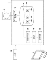
以下、図面を参照して本発明の実施形態について説明する。図1は本発明の実施形態による医用画像変換装置の構成を示す概略ブロック図である。なお、図1に示す医用画像変換装置1の構成は、補助記憶装置に読み込まれた医用画像変換処理プログラムをコンピュータ上で実行することにより実現される。このとき、この医用画像変換処理プログラムは、CD−ROM等の記憶媒体に記憶され、もしくはインターネット等のネットワークを介して配布され、コンピュータにインストールされる。
Hereinafter, embodiments of the present invention will be described with reference to the drawings. FIG. 1 is a schematic block diagram showing a configuration of a medical image conversion apparatus according to an embodiment of the present invention. The configuration of the medical
本実施形態による医用画像変換装置1は、ボリュームデータ取得部10、記憶部20、位置合わせ部30、変換部40、表示制御部50および入力部60を備える。
The medical
ボリュームデータ取得部10は、CT装置またはMRI装置等のモダリティ2において、所定の時間間隔Δtで被写体の特定臓器を撮影して得られた複数の3次元ボリュームデータ100からなる3次元ボリュームデータ群110を取得する、通信インターフェースの機能を有する。なお、3次元ボリュームデータ群110はLAN経由でモダリティ2から送信される。また、本実施形態においては、特定臓器を心臓とする。
The volume
ここで、3次元ボリュームデータ100は、診断対象となる心臓を断層面に垂直な方向に沿って順に得られる2次元の断層像データを積層することによって取得されるものであり、本実施形態においては、CT装置またはMRI装置等のモダリティ2において撮影された複数の断層画像を重ね合わせることにより生成される。なお、CT装置を用いて取得したボリュームデータは、ボクセル(すなわち画素位置)毎にX線の吸収量を蓄えたデータとなり、各画素位置に対して1つの信号値(CT装置で撮影した場合は、X線の吸収量を示す値)が与えられたデータとなる。
Here, the three-
3次元ボリュームデータ群110は、例えば、被写体を一定の時間間隔Δtからなる異なる時相t1、t2、・・・、tnで撮影を行うことにより取得した、一連の3次元ボリュームデータ100から構成される。
The three-dimensional
なお、3次元ボリュームデータ100には、DICOM(Digital Imaging and Communications in Medicine)規格で規定された付帯情報が付加される。付帯情報は、例えば、個々の3次元ボリュームデータ100により表される3次元画像を識別するための画像ID、被写体を識別するための患者ID、検査を識別するための検査ID、画像情報毎に割り振られるユニークなID(UID)、その画像情報が生成された検査日、検査時刻、その画像情報を取得するための検査で使用されたモダリティの種類、患者氏名、年齢、性別等の患者情報、検査部位(撮影部位、本実施形態においては心臓)、撮影条件(造影剤の使用有無や、放射線量等)、1回の検査で複数の画像を取得したときのシリーズ番号あるいは採取番号等の情報が含まれうる。
The three-
記憶部20は、ハードディスク等の大容量の記憶装置であり、3次元ボリュームデータ群110が記憶される。なお、記憶部20には、被写体が異なる(すなわち患者が異なる)、あるいは同一被写体で撮影時期が異なる複数の3次元ボリュームデータ群110が記憶される。
The
位置合わせ部30は、3次元ボリュームデータ100のそれぞれについて、心臓部分における対応する画素位置を3次元ボリュームデータ100間において位置合わせする。具体的には、「W.M. Wells III, P. Viola, H. Atsumi, S. Nakajima, and R.Kikinis, Multi modal volume registration by maximization of mutual information , Med. Image Anal., vol.1, no.1, pp.35 51,1996.」(参考文献1)、「Rueckert, D., Sonoda, L.I., Hayes, C., Hill, D.L.G.,Leach, M.O., Hawkes, D.J., Nonrigid registration using free-form deformations: application to breast MR images. IEEE Transactions on Medical Imaging, vol.18, pp.712?721, 1999.」(参考文献2)、「Masumoto J, Sato Y, Hori M, Murakami T, Johkoh T, Nakamura H, Tamura S: A similarity measure for nonrigid volume registration using known joint distribution of target tissue: Application to dynamic CT data of the liver, Medical Image Analysis, vol.7, no.4, pp.553-564, 2003.」(参考文献3)、「Yongmei Wang, Lawrence H. Staib, Physical model-based non-rigid registration incorporating statistical shape information, Medical Image Analysis (2000) volume 4, number 1, pp 7-21」(参考文献4)に記載された手法を用いて対応する画素位置を対応づけることができる。
The
参考文献1に記載された手法は、剛体レジストレーション手法を用いた位置合わせを行うものであり、異なるモダリティにより取得した3次元医用画像間において、相互情報量が最大となるように、画素の位置および方向を調整することにより画素の位置合わせを行う手法である。参考文献2に記載された手法は、非剛体レジストレーション手法を用いた位置合わせを行うものであり、"free from deformation"(FFT)というBスプライン関数を基本とした変形推定手法により、MRI画像の位置合わせを行う手法である。参考文献3に記載された手法は、非剛体レジストレーション手法を用いた位置合わせを行うものであり、時系列順に取得されたCT画像において、肝臓等の対象とする組織の結合分布(joint distribution)を用いて、対象組織と非対象組織との境界において組織をスライドさせることにより類似度を測定して位置合わせを行う手法である。参考文献4に記載された手法は、非剛体レジストレーション手法を用いた位置合わせを行うものであり、物体の形状をあらかじめ与えておき、その形状となるように物体を変形させることにより、物体間の位置合わせを行う手法である。
The technique described in
また、特表2005−528974号公報および特表2007−516744号公報に記載された手法を用いることも可能である。特表2005−528974号公報に記載された手法は、対象の関心領域から第1および第2の画像データセットを取得し、関心領域に対する呼吸および心臓運動等の生理学的運動のモデルを作成し、生理学的モデルを第1の画像データセットに対して適合させ、変換のために対象特有の生理学的ファントムを第2の画像データセットに適用し、この変換を第1の画像データセットに対して適用することにより、位置合わせを行う手法である。 Moreover, it is also possible to use the technique described in the Japanese translations of PCT publication No. 2005-528974 gazette and the Japanese translations of PCT publication 2007-516744 gazette. The technique described in JP 2005-528974 A acquires first and second image data sets from a region of interest of a target, creates a model of physiological motion such as respiration and heart motion with respect to the region of interest, Fit a physiological model to the first image data set, apply an object-specific physiological phantom to the second image data set for conversion, and apply the conversion to the first image data set This is a technique for performing alignment.
また、特表2007−516744号公報に記載された手法は、2つの画像間における目印となる位置の類似性に基づいて、目印の位置を位置合わせすることにより画像の位置合わせを行う手法である。 The technique described in JP-T-2007-516744 is a technique for aligning images by aligning the positions of the landmarks based on the similarity of the positions of the landmarks between the two images. .
位置合わせ部30は、これらの手法を用いて3次元ボリュームデータ100により表される3次元画像に含まれる心臓間の位置合わせを行う。これにより、3次元画像に含まれる心臓間において、同一位置を表す画素が互いに対応づけられる。
The
なお、位置合わせ手法は上記各種法に限定されるものではなく、公知の任意の手法を用いることができる。また、3次元ボリュームデータ100を順次モニタ4に表示し、入力部60からの入力により操作者が位置合わせを行うようにしてもよい。また、心臓部分のみならず、3次元ボリュームデータ100の全画素位置の位置合わせを行うようにしてもよい。
The alignment method is not limited to the above-described various methods, and any known method can be used. Alternatively, the three-
図2は、心臓の3次元画像の位置合わせ結果を示す図である。なお、図2においては、3つの3次元ボリュームデータ100A,100B,100Cに含まれる心臓の位置合わせ結果を示す。図2に示すように、3次元ボリュームデータ100Aに含まれる心臓上の画素P1は、3次元ボリュームデータ100B,100Cの画素P2,P3とそれぞれ対応づけられることとなる。
FIG. 2 is a diagram showing the alignment result of the three-dimensional image of the heart. FIG. 2 shows the alignment result of the heart included in the three three-
変換部40は、3次元ボリュームデータ100のそれぞれの画素位置における信号値を、ボリュームレンダリング(VR)表示のために表示画素値に変換する。図3は、3次元ボリュームデータ100を変換するためのカラーテンプレートを示す図である。なお、カラーテンプレートは、3次元ボリュームデータ100に含まれる部位のうち、抽出してVR表示したい部位に応じて複数用意されており、本実施形態においては、心臓のVR表示のためのカラーテンプレートT0を選択するものとする。図3に示すように、カラーテンプレートT0は横軸に3次元ボリュームデータ100の信号値、縦軸に色(R,G,B)および不透明度が設定された1次元のルックアップテーブルである。なお、図3においては1つのカラーテンプレートのみを示しているが、実際には、R,G,Bの各色および不透明度のそれぞれについて4つのカラーテンプレートが用意されている。
The
変換部40は、カラーテンプレートT0を参照して、3次元ボリュームデータ100の各画素の信号値を、R,G,Bおよび不透明度からなる表示画素値に変換する。この際、変換部40は、複数の3次元ボリュームデータ100のそれぞれの時相のうちの基準となる1つの基準時相Bを選択する。そして、基準時相以外の時相における3次元ボリュームデータ100の各画素位置の信号値を、基準時相Bにおける3次元ボリュームデータ(以下、基準3次元ボリュームデータ120とする)の対応する画素位置の信号値に変換する。
The
なお、基準時相Bの選択は、例えば、3次元ボリュームデータ群110の時相における先頭の時相、中間の時相、最後の時相、あるいはノイズが最も少ない3次元ボリュームデータ100を取得した時相等、あらかじめ定められた時相を選択するするようにすればよい。また、入力部60からの入力によりいずれの時相を基準時相Bとするかの選択を受け付けるようにしてもよい。この際、操作者は最もノイズが少ない3次元ボリュームデータ100を取得した時相等を基準時相Bとして選択すればよい。
The selection of the reference time phase B is, for example, the acquisition of the three-
そして、変換部40は、すべての3次元ボリュームデータ100の各画素位置の信号値を基準3次元ボリュームデータ120の対応する画素位置の信号値に変換した後に、カラーテンプレートT0を用いて、各3次元ボリュームデータ100の信号値を表示画素値に変換する。これにより、3次元ボリュームデータ100は、心臓が抽出されたVR画像を表すものとなる。
Then, the
またこれにより、図2に示す3つの3次元ボリュームデータ100A,100B,100Cの対応する画素位置P1,P2,P3は、例えばそれぞれの信号値がノイズ等の影響により100,110,107となっている場合であっても、同じ色および不透明度の表示画素値に変換されることとなる。例えば、3つの3次元ボリュームデータ100A,100B,100Cのうち、基準時相Bにおける3次元ボリュームデータを3次元ボリュームデータ100Bとした場合、画素位置P1,P3の信号値はそれぞれ110に変換され、その結果、カラーテンプレートT0における110の信号値に対応する色および不透明度に変換されることとなる。
As a result, the corresponding pixel positions P1, P2, and P3 of the three three-
表示制御部50は、変換された一連の3次元ボリュームデータ100により表されるVR画像を時系列順にディスプレイ4に表示する。なお、本実施形態においては、心臓を表示するものであるため、心臓が拍動する様子がディスプレイ4に表示されることとなる。
The
入力部60は、キーボードおよびマウス等の公知の入力装置からなる。
The
次いで、本実施形態において行われる処理について説明する。図4は本実施形態において行われる処理を示すフローチャートである。なお、複数の心臓の3次元ボリュームデータ群110は、ボリュームデータ取得部10により取得されて、記憶部20に記憶されているものとする。操作者が入力部60を操作することにより、表示する3次元画像の選択がなされると(ステップST1肯定)、位置合わせ部30が、選択された3次元画像に対応する3次元ボリュームデータ群110を記憶部20から読み出し、3次元ボリュームデータ群110を構成する3次元ボリュームデータ100間の画素位置を位置合わせする(ステップST2)。これにより、3次元ボリュームデータ100間の画素位置が対応づけられる。
Next, processing performed in the present embodiment will be described. FIG. 4 is a flowchart showing processing performed in the present embodiment. A plurality of three-dimensional
そして、変換部40が、基準時相Bを選択し(ステップST3)、すべての3次元ボリュームデータ100の各画素位置の信号値を、基準時相Bにおける基準3次元ボリュームデータ120の対応する画素位置の信号値に変換し(ステップST4)、さらに、選択されたカラーテンプレートT0を用いて、各3次元ボリュームデータ100の信号値を表示画素値に変換する(ステップST5)。そして、表示制御部50が、変換された3次元ボリュームデータ100により表される心臓のVR画像をディスプレイ4に時系列順に表示し(ステップST6)、処理を終了する。
Then, the
このように、本実施形態においては、位置合わせ部30が、3次元ボリュームデータ群110を構成する3次元ボリュームデータ100の画素位置を、3次元ボリュームデータ100間において位置合わせすることにより対応づけ、変換部40が基準時相Bを選択し、すべての3次元ボリュームデータ100の各画素位置の信号値を基準時相Bにおける基準3次元ボリュームデータ120の対応する画素位置の信号値に変換し、さらにカラーテンプレートT0を用いて、各3次元ボリュームデータ100の信号値を、R,G,Bおよび不透明度からなる表示信号値に変換するようにしたものである。
Thus, in the present embodiment, the
このため、3次元ボリュームデータ群110を時系列順に表示した場合に、心臓内のある画素位置における色および不透明度が、心臓の動きに併せて変動することがなくなる。したがって、心臓内の色および不透明度が変動することによる心臓の3次元的な動きを錯覚することがなくなり、その結果、時系列順に表示された3次元ボリュームデータ群110を用いての診断を正確に行うことができる。
For this reason, when the three-dimensional
なお、上記実施形態においては、心臓の3次元ボリュームデータ群を用いているが、肺の3次元ボリュームデータ群を用いてもよい。この場合、呼吸による肺の3次元的な動きを表すように、VR画像が4次元表示されることとなる。また、心臓および肺の双方を含む循環器系の3次元ボリュームデータ群を用いてもよい。この場合、心臓の拍動による3次元的な動きおよび呼吸による肺の3次元的な動きの双方を表すように、VR画像が4次元表示されることとなる。 In the above embodiment, a three-dimensional volume data group of the heart is used, but a three-dimensional volume data group of the lung may be used. In this case, the VR image is displayed in four dimensions so as to represent the three-dimensional movement of the lungs due to respiration. Further, a three-dimensional volume data group of the circulatory system including both the heart and the lung may be used. In this case, the VR image is displayed four-dimensionally so as to represent both the three-dimensional movement due to the heartbeat and the three-dimensional movement of the lung due to breathing.
また、上記実施形態において、図5に示すように、平滑化部70を設け、3次元ボリュームデータ100間の画素位置を位置合わせする前に、各3次元ボリュームデータ100を平滑化するようにしてもよい。具体的には、所定サイズ(例えば3×3×3)の平滑化フィルタを用いて、3次元ボリュームデータ100の各画素位置の信号値の平均値を算出することにより、各3次元ボリュームデータ100を平滑化すればよい。これにより、位置合わせを行う場合に、3次元ボリュームデータ100に含まれるノイズの影響を低減できるため、より正確に位置合わせを行うことができる。
Further, in the above embodiment, as shown in FIG. 5, a smoothing
また、上記実施形態においては、心臓の3次元ボリュームデータ群110を時系列順にVR表示する場合について説明しているが、各3次元ボリュームデータ100の同一位置のスライス面における心臓の断面を表す2次元画像を3次元ボリュームデータ100からそれぞれ抽出し、抽出した2次元画像の濃度および/または色を変換して時系列順に表示する場合にも、本発明を適用できることはもちろんである。また、時系列画像としては、3次元ボリュームデータ100に限定されるものではなく、単純X線撮影により所定の時間間隔により取得した一連の画像からなる画像群を用いることも可能である。
In the above-described embodiment, the case is described in which the three-dimensional
1 医用画像変換装置
2 モダリティ
4 ディスプレイ
10 ボリュームデータ取得部
20 記憶部
30 位置合わせ部
40 変換部
50 表示制御部
60 入力部
70 平滑化部
100 3次元ボリュームデータ
110 3次元ボリュームデータ群
DESCRIPTION OF
Claims (7)
前記一連の時系列医用画像内の画素位置を、前記一連の時系列医用画像間において位置合わせする位置合わせ手段と、
前記一連の時系列医用画像において、前記心臓および/または肺の対応する画素位置の信号値を同一の表示画素値に変換する変換手段とを備えたことを特徴とする医用画像変換装置。 A series of images in which the heart and / or lungs of the same subject can be replayed by displaying the heart and / or lung movements in time-sequential order obtained by continuously taking images at short time intervals. Image acquisition means for acquiring time-series medical images;
Alignment means for aligning pixel positions in the series of time-series medical images between the series of time-series medical images;
A medical image conversion apparatus comprising: conversion means for converting a signal value at a corresponding pixel position of the heart and / or lung into the same display pixel value in the series of time-series medical images.
前記一連の時系列医用画像内の画素位置を、前記一連の時系列医用画像間において位置合わせし、
前記一連の時系列医用画像において、前記心臓および/または肺の対応する画素位置の信号値を同一の表示画素値に変換することを特徴とする医用画像変換方法。 A series of images in which the heart and / or lungs of the same subject can be replayed by displaying the heart and / or lung movements in time-sequential order obtained by continuously taking images at short time intervals. Acquire time series medical images,
Aligning pixel positions in the series of time-series medical images between the series of time-series medical images;
A medical image conversion method, comprising: converting a signal value of a corresponding pixel position of the heart and / or lung into the same display pixel value in the series of time-series medical images.
前記一連の時系列医用画像内の画素位置を、前記一連の時系列医用画像間において位置合わせする手順と、
前記一連の時系列医用画像において、前記心臓および/または肺の対応する画素位置の信号値を同一の表示画素値に変換する手順とを有することを特徴とする医用画像変換方法をコンピュータに実行させるためのプログラム。 A series of images in which the heart and / or lungs of the same subject can be replayed by displaying the heart and / or lung movements in time-sequential order obtained by continuously taking images at short time intervals. A procedure for acquiring time-series medical images;
A procedure for aligning pixel positions in the series of time-series medical images between the series of time-series medical images;
In the series of time-series medical images, the computer has a procedure for converting a signal value at a corresponding pixel position of the heart and / or lung into the same display pixel value. Program for.
Priority Applications (5)
| Application Number | Priority Date | Filing Date | Title |
|---|---|---|---|
| JP2010063411A JP5068336B2 (en) | 2010-03-19 | 2010-03-19 | Medical image conversion apparatus and method, and program |
| US13/635,605 US9295442B2 (en) | 2010-03-17 | 2011-03-17 | Medical image conversion apparatus, method and program |
| EP11755924A EP2548511A1 (en) | 2010-03-17 | 2011-03-17 | Medical image conversion device, method, and program |
| CN201180014344.2A CN102802534B (en) | 2010-03-17 | 2011-03-17 | Medical image conversion device, method, and program |
| PCT/JP2011/001568 WO2011114733A1 (en) | 2010-03-17 | 2011-03-17 | Medical image conversion device, method, and program |
Applications Claiming Priority (1)
| Application Number | Priority Date | Filing Date | Title |
|---|---|---|---|
| JP2010063411A JP5068336B2 (en) | 2010-03-19 | 2010-03-19 | Medical image conversion apparatus and method, and program |
Publications (3)
| Publication Number | Publication Date |
|---|---|
| JP2011193997A JP2011193997A (en) | 2011-10-06 |
| JP2011193997A5 JP2011193997A5 (en) | 2012-02-02 |
| JP5068336B2 true JP5068336B2 (en) | 2012-11-07 |
Family
ID=44872944
Family Applications (1)
| Application Number | Title | Priority Date | Filing Date |
|---|---|---|---|
| JP2010063411A Active JP5068336B2 (en) | 2010-03-17 | 2010-03-19 | Medical image conversion apparatus and method, and program |
Country Status (1)
| Country | Link |
|---|---|
| JP (1) | JP5068336B2 (en) |
Families Citing this family (1)
| Publication number | Priority date | Publication date | Assignee | Title |
|---|---|---|---|---|
| JP5879098B2 (en) * | 2011-11-01 | 2016-03-08 | 公立大学法人会津大学 | Body organ moving image generation apparatus and body organ moving image generation method |
Family Cites Families (8)
| Publication number | Priority date | Publication date | Assignee | Title |
|---|---|---|---|---|
| JPH10108073A (en) * | 1996-09-27 | 1998-04-24 | Fuji Photo Film Co Ltd | Method and device for processing bone part image |
| US7609876B2 (en) * | 2004-10-22 | 2009-10-27 | Siemens Medical Solutions Usa, Inc. | Virtual grid alignment of sub-volumes |
| JP4651375B2 (en) * | 2004-12-16 | 2011-03-16 | 株式会社日立メディコ | Medical image display apparatus and method |
| JP2007159643A (en) * | 2005-12-09 | 2007-06-28 | Canon Inc | Image processing device and method |
| JP5389324B2 (en) * | 2006-12-18 | 2014-01-15 | ジーイー・メディカル・システムズ・グローバル・テクノロジー・カンパニー・エルエルシー | X-ray tomography equipment |
| JP5591440B2 (en) * | 2007-01-17 | 2014-09-17 | 株式会社東芝 | Medical image display device |
| JP4979125B2 (en) * | 2007-05-18 | 2012-07-18 | 富士フイルム株式会社 | Radiation imaging system and program |
| JP2010000306A (en) * | 2008-06-23 | 2010-01-07 | Toshiba Corp | Medical image diagnostic apparatus, image processor and program |
-
2010
- 2010-03-19 JP JP2010063411A patent/JP5068336B2/en active Active
Also Published As
| Publication number | Publication date |
|---|---|
| JP2011193997A (en) | 2011-10-06 |
Similar Documents
| Publication | Publication Date | Title |
|---|---|---|
| US9117287B2 (en) | Image analysis apparatus, method, and program | |
| JP6073971B2 (en) | Medical image processing device | |
| US10304198B2 (en) | Automatic medical image retrieval | |
| WO2011114733A1 (en) | Medical image conversion device, method, and program | |
| US7899231B2 (en) | System and method for splicing medical image datasets | |
| JP5580030B2 (en) | Image processing apparatus and image alignment method | |
| US10803354B2 (en) | Cross-modality image synthesis | |
| US7778453B2 (en) | Multi-modality method and software for representation and evaluation of extremity exposures of arthritis/arthrosis patients | |
| JPH10137231A (en) | Medical image processor | |
| JP5415245B2 (en) | MEDICAL IMAGE DISPLAY DEVICE, METHOD, AND PROGRAM | |
| JP6772123B2 (en) | Image processing equipment, image processing methods, image processing systems and programs | |
| EP3545845A1 (en) | Method for processing computed tomography imaging data of a suspect`s respiratory system | |
| JP6301277B2 (en) | Diagnostic auxiliary image generation apparatus, diagnostic auxiliary image generation method, and diagnostic auxiliary image generation program | |
| US9224188B2 (en) | Image processing device, method and program | |
| KR101028798B1 (en) | Method for detection of hepatic tumors using registration of multi-phase liver CT images | |
| JP6734111B2 (en) | Finding information creation device and system | |
| JP5068334B2 (en) | Medical image conversion apparatus and method, and program | |
| JP5068336B2 (en) | Medical image conversion apparatus and method, and program | |
| EP4231234A1 (en) | Deep learning for registering anatomical to functional images | |
| JP2019088672A (en) | Image processing device, method for operating image processing device and image processing program | |
| CN115546174B (en) | Image processing method, device, computing equipment and storage medium | |
| Viola et al. | High-Quality 3D Visualization of In-Situ Ultrasonography. | |
| JP2009018029A (en) | Medical image processing apparatus and medical image diagnosis apparatus | |
| WO2017018230A1 (en) | Image processing device, method, and program |
Legal Events
| Date | Code | Title | Description |
|---|---|---|---|
| A521 | Request for written amendment filed |
Free format text: JAPANESE INTERMEDIATE CODE: A523 Effective date: 20111208 |
|
| A621 | Written request for application examination |
Free format text: JAPANESE INTERMEDIATE CODE: A621 Effective date: 20111208 |
|
| A871 | Explanation of circumstances concerning accelerated examination |
Free format text: JAPANESE INTERMEDIATE CODE: A871 Effective date: 20111208 |
|
| A975 | Report on accelerated examination |
Free format text: JAPANESE INTERMEDIATE CODE: A971005 Effective date: 20120124 |
|
| A131 | Notification of reasons for refusal |
Free format text: JAPANESE INTERMEDIATE CODE: A131 Effective date: 20120131 |
|
| A521 | Request for written amendment filed |
Free format text: JAPANESE INTERMEDIATE CODE: A523 Effective date: 20120306 |
|
| A131 | Notification of reasons for refusal |
Free format text: JAPANESE INTERMEDIATE CODE: A131 Effective date: 20120508 |
|
| A521 | Request for written amendment filed |
Free format text: JAPANESE INTERMEDIATE CODE: A523 Effective date: 20120614 |
|
| TRDD | Decision of grant or rejection written | ||
| A01 | Written decision to grant a patent or to grant a registration (utility model) |
Free format text: JAPANESE INTERMEDIATE CODE: A01 Effective date: 20120731 |
|
| A01 | Written decision to grant a patent or to grant a registration (utility model) |
Free format text: JAPANESE INTERMEDIATE CODE: A01 |
|
| A61 | First payment of annual fees (during grant procedure) |
Free format text: JAPANESE INTERMEDIATE CODE: A61 Effective date: 20120814 |
|
| FPAY | Renewal fee payment (event date is renewal date of database) |
Free format text: PAYMENT UNTIL: 20150824 Year of fee payment: 3 |
|
| R150 | Certificate of patent or registration of utility model |
Ref document number: 5068336 Country of ref document: JP Free format text: JAPANESE INTERMEDIATE CODE: R150 Free format text: JAPANESE INTERMEDIATE CODE: R150 |
|
| R250 | Receipt of annual fees |
Free format text: JAPANESE INTERMEDIATE CODE: R250 |
|
| R250 | Receipt of annual fees |
Free format text: JAPANESE INTERMEDIATE CODE: R250 |
|
| R250 | Receipt of annual fees |
Free format text: JAPANESE INTERMEDIATE CODE: R250 |
|
| R250 | Receipt of annual fees |
Free format text: JAPANESE INTERMEDIATE CODE: R250 |
|
| R250 | Receipt of annual fees |
Free format text: JAPANESE INTERMEDIATE CODE: R250 |
|
| R250 | Receipt of annual fees |
Free format text: JAPANESE INTERMEDIATE CODE: R250 |
|
| R250 | Receipt of annual fees |
Free format text: JAPANESE INTERMEDIATE CODE: R250 |
|
| R250 | Receipt of annual fees |
Free format text: JAPANESE INTERMEDIATE CODE: R250 |
|
| R250 | Receipt of annual fees |
Free format text: JAPANESE INTERMEDIATE CODE: R250 |