JP5067670B2 - Machine controller system - Google Patents
Machine controller system Download PDFInfo
- Publication number
- JP5067670B2 JP5067670B2 JP2008227280A JP2008227280A JP5067670B2 JP 5067670 B2 JP5067670 B2 JP 5067670B2 JP 2008227280 A JP2008227280 A JP 2008227280A JP 2008227280 A JP2008227280 A JP 2008227280A JP 5067670 B2 JP5067670 B2 JP 5067670B2
- Authority
- JP
- Japan
- Prior art keywords
- slave
- scan
- master
- synchronization
- controller
- Prior art date
- Legal status (The legal status is an assumption and is not a legal conclusion. Google has not performed a legal analysis and makes no representation as to the accuracy of the status listed.)
- Active
Links
Images


Landscapes
- Programmable Controllers (AREA)
Description
本発明は、複数台のコントローラの組み合わせによる分散制御をおこなうマシンコントローラ装置に関する。 The present invention relates to a machine controller device that performs distributed control by a combination of a plurality of controllers.
PLC機能を持つマシンコントローラを使用する機械装置においては、シーケンス制御やモーション制御の高度化・複雑化が進み、一つの装置を機能毎にセクション化し、それぞれにマシンコントローラを配置して、各セクションが協調した動作を行なうという用途が増えている。
このような機械装置のセクション化には、セクション毎に追加・入れ替えをおこない、容易に用途に応じた機械構成に変更するため、という目的もある。
このように、機械装置をセクション化、すなわち分散制御にて構成する場合、装置が十分な性能を発揮するためには、個々のセクション間の同期性が保証されている事が求められる。
従来、このような装置は、分散化されたコントローラが、ネットワーク等の通信手段によりデータや信号の受け渡しを行なうことで実現していた。
あるいは、同じ入力信号を分散化された全てのコントローラ入力し、その信号をトリガとして動作をおこなうことで同期を実現していた。
たとえば、特許文献1(図1、図4、図7)では、1のコントローラと他のコントローラがデータリンクで接続された分散システムが開示されている。
In machine devices that use machine controllers with PLC functions, the advancement and complexity of sequence control and motion control has progressed, and one device has been divided into sections for each function. Applications that perform coordinated operations are increasing.
The sectioning of such a mechanical device also has an object of adding or replacing each section and easily changing the machine configuration according to the application.
As described above, when the mechanical device is configured by sectioning, that is, distributed control, in order for the device to exhibit sufficient performance, it is required that the synchronism between individual sections is guaranteed.
Conventionally, such a device has been realized by a decentralized controller exchanging data and signals through communication means such as a network.
Alternatively, the same input signal is input to all distributed controllers, and synchronization is realized by performing an operation using the signal as a trigger.
For example, Patent Document 1 (FIGS. 1, 4, and 7) discloses a distributed system in which one controller and another controller are connected by a data link.
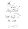
複数のマシンコントローラを通信手段にて接続し、分散制御を行なう場合の構成を図11に示す。図11において、1はプログラム入力装置であり、アプリケーションプログラムS1を作成して出力する。2はマスタコントローラであり、CPUモジュール3と通信モジュール4から構成されている。CPUモジュール3はアプリケーションプログラムS1の処理手順に従い、通信モジュール4との間でバスを通して入出力データS2を授受する。入出力データS2の授受を行うタイミング、及び、アプリケーションプログラムを実行するタイミング、すなわちスキャン周期は、一般にCPUモジュール3に搭載された水晶発振子が発生するクロックを基にして作成される。
通信モジュール4は、スレーブコントローラ51〜5Nとの間で通信データS3を定周期の通信周期で送受信する。
スレーブコントローラ51〜5Nもマスタコントローラ2と同様、プログラム入力装置1にて作成したアプリケーションプログラムが格納されている。スレーブコントローラ51〜5Nに接続されるプログラム入力装置1を破線で示しているのは、必要に応じて接続されることを意味する。
FIG. 11 shows a configuration in which a plurality of machine controllers are connected by communication means to perform distributed control. In FIG. 11,
The
Similarly to the
図11において、マスタコントローラ2からの指令データは、スレーブコントローラ51〜5Nに送信される。スレーブコントローラ51〜5Nは、受信した指令データを、アプリケーションプログラムの処理手順に従い、処理を実行し、実行した結果を応答データとしてマスタコントローラ2に返信する。
マスタコントローラ2は、スレーブコントローラ51〜5Nの応答データより、アプリケーションプログラムの歩進を管理する。
なお、図12にスレーブコントローラ51〜5Nのブロック図を示すが、独自のスレーブ基準周期発生回路16sとその出力であるスレーブ基準周期信号S14sを基にスレーブスキャン周期信号S15sを発生するスレーブスキャン周期発生回路17sを有している。スレーブコントローラ51〜5Nは、スレーブスキャン周期発生回路17sが発生させるスレーブスキャン周期信号S15sに基づいてスキャン動作を実行する。
In FIG. 11, the command data from the
The
FIG. 12 shows a block diagram of the
このような構成の制御システムでは、マスタスキャン周期(マスタコントローラ2のスキャン周期)と各スレーブスキャン周期(スレーブコントローラ51〜5Nのスキャン周期)は、特許文献1の場合と同様、同期していない。
また、マスタコントローラ2と各スレーブコントローラが備える水晶発振子には、固体差があるため、例え同じスキャン周期を設定しても、そのスキャン周期に微少なずれが生じる。このスキャン周期のずれが蓄積すると、各コントローラの動作タイミングのずれが生じる。
そのため、マスタコントローラ2からの指令データがスレーブコントローラ51〜5Nに伝わるタイミングがずれたり、アプリケーションによる動作開始タイミングがずれるなど、セクション間の同期性能が求められる用途においては問題があった。
また、各スレーブコントローラに接続されている機器によって、スキャン周期を変えたいという要求もあった。たとえば、高速性が要求されるサーボ機器を制御する場合はスキャン周期を短くし汎用のI/O機器との入出力はスキャン周期を長くするなどである。
In the control system having such a configuration, the master scan cycle (scan cycle of the master controller 2) and each slave scan cycle (scan cycles of the
Further, since the crystal oscillators included in the
For this reason, there is a problem in applications where synchronization performance between sections is required such that the timing at which command data from the
There is also a request to change the scan cycle depending on the device connected to each slave controller. For example, when controlling a servo device requiring high speed, the scan cycle is shortened, and input / output with a general-purpose I / O device is lengthened.
I/Oの入力信号で同期をおこなう構成をとった場合も、各コントローラのスキャン周期の微小なずれの蓄積により、入力信号を取り込むタイミングにずれが生じるため、セクション間の同期性能が求められる用途においては問題があった。
本発明は、このような問題や要求に対応するために、スレーブコントローラのスキャン周期をマスタコントローラのスキャン周期に同期させることができ、さらには、スレーブコントローラのスキャン周期をマスタコントローラのスキャン周期の整数倍または1/整数倍に設定することができるマシンコントローラシステムを提供することを目的としている。 In order to address such problems and requirements, the present invention can synchronize the scan cycle of the slave controller with the scan cycle of the master controller. Furthermore, the scan cycle of the slave controller is an integer of the scan cycle of the master controller. An object of the present invention is to provide a machine controller system that can be set to a multiple or 1 / integer multiple.
請求項1に記載の発明は、1台のマスタコントローラと1台または複数台のスレーブコントローラが通信ネットワークで接続され、前記マスタコントローラが通信周期毎に、前記スレーブコントローラに対して同期フレームを同報送信するマシンコントローラシステムにおいて、
前記スレーブコントローラは、
CPUと、
スレーブ基準周期信号を発生するスレーブ基準周期発生回路と、
前記スレーブ基準周期信号を計数してスレーブスキャン周期信号を発生するスレーブスキャン周期発生回路と、
スレーブスキャン周期を前記マスタコントローラのマスタスキャン周期に同期させる同期許可部と、
を備え、
前記同期許可部は、
前記CPUによって同期許可信号が前記同期許可部に書き込まれた後に、初回の同期フレーム信号を受信した際に初回フラグおよびエッジ信号を出力し、2回目以降の前記同期フレーム信号を受信した際には前記エッジ信号のみを出力し、
前記スレーブスキャン周期発生回路は、
前記初回フラグと前記エッジ信号がともに入力された場合に限りリセットされ、前記初回フラグが入力されている場合は前記スレーブスキャン周期信号を出力しないことを特徴とするものである。
According to the first aspect of the present invention, one master controller and one or a plurality of slave controllers are connected via a communication network, and the master controller broadcasts a synchronization frame to the slave controller every communication cycle. In the machine controller system that sends
The slave controller is
CPU,
And slave reference period generation circuit for generating a slave reference period signal,
And slave scan cycle generating circuit for generating a slave scan cycle signal by counting the slave reference periodic signal,
A synchronization permission unit for synchronizing the slave scan cycle master scan cycle of the master controller,
With
The synchronization permission unit
After synchronization permission signal is written to the synchronous authorization unit by the CPU, when outputting the first flag and an edge signal upon receiving a synchronization frame signal for the first time, receiving the synchronization frame signal of second and subsequent Outputs only the edge signal,
The slave scan cycle generation circuit
It is reset only when both the initial flag and the edge signal are input, and when the initial flag is input, the slave scan cycle signal is not output.
請求項2に記載の発明は、請求項1に記載の発明において、前記スレーブ基準周期発生回路は、前記エッジ信号の入力によりリセットされ、前記初回フラグが入力されている場合はスレーブ基準周期信号を出力しないことを特徴とするものである。
According to a second aspect of the present invention, in the first aspect of the invention, the slave reference period generation circuit is reset by the input of the edge signal, and the slave reference period signal is output when the initial flag is input. It is characterized by not outputting .
請求項3に記載の発明は、請求項1又は請求項2のいずれか1項に記載の発明において、前記スレーブコントローラは、同期可否判断として前記スレーブスキャン周期が前記マスタスキャン周期の整数倍または整数分の1倍であるときに限り同期可能と判断し、前記スレーブスキャン周期を前記マスタスキャン周期に同期させることを特徴とするものである。
According to a third aspect of the present invention, in the first or second aspect of the present invention, the slave controller is configured such that the slave scan period is an integer multiple or an integer of the master scan period in order to determine whether synchronization is possible. It is determined that synchronization is possible only when it is 1 / minute, and the slave scan period is synchronized with the master scan period.
請求項4に記載の発明は、請求項3に記載の発明において、前記マスタコントローラは前記マスタスキャン周期のデータを格納した送信データを前記スレーブコントローラに送信し、
前記スレーブコントローラは前記同期可否判断の結果を前記マスタコントローラに返信し、
前記マスタコントローラは、前記スレーブコントローラが同期可能であることを返信した場合に、同期開始要求、および前記マスタスキャン周期を前記通信周期で計数したスキャンカウンタ値を前記スレーブコントローラに送信し、
前記スレーブコントローラは、前記同期開始要求および前記スキャンカウンタ値を受信したときに、同期化処理を行い、該同期化処理が完了したら前記マスタコントローラへ同期完了を示すステータスがセットされた応答データを送信することを特徴とするものである。
The invention according to
The slave controller returns a result of the synchronization determination to the master controller,
When the master controller returns that the slave controller can be synchronized, a synchronization start request and a scan counter value obtained by counting the master scan period in the communication period are transmitted to the slave controller,
When the slave controller receives the synchronization start request and the scan counter value, the slave controller performs a synchronization process, and when the synchronization process is completed, transmits response data in which a status indicating completion of synchronization is set to the master controller It is characterized by doing.
請求項5に記載の発明は、請求項4に記載の発明において、前記同期化処理において、前記CPUが、前記マスタコントローラから送信される前記スキャンカウンタ値を監視してマスタスキャン開始タイミングの検出を行ない、該マスタスキャン開始タイミングを検出すると、前記同期許可信号を前記同期許可部に書き込んで行うことを特徴とするものである。 According to a fifth aspect of the present invention, in the invention according to the fourth aspect, in the synchronization process, the CPU monitors the scan counter value transmitted from the master controller to detect a master scan start timing. When the master scan start timing is detected, the synchronization permission signal is written in the synchronization permission unit.
請求項6に記載の発明は、請求項5に記載の発明において、前記マスタスキャン開始タイミングの検出は、前記スキャンカウンタ値があらかじめ設定された値と等しいか否かを判断することによって行われるものであることを特徴とするものである。
According to a sixth aspect of the invention, in the fifth aspect of the invention, the detection of the master scan start timing is performed by determining whether or not the scan counter value is equal to a preset value. It is characterized by being.
本発明によれば、スレーブコントローラのスキャン周期がマスタコントローラのスキャン周期の整数倍または整数分の1倍であれば、スレーブコントローラのスキャン周期をマスタコントローラのスキャン周期に同期させることが可能である。
また、スレーブコントローラ毎に異なったスキャン周期を設定することができるので、各スレーブコントローラでは実際に求められる制御性能に見合ったCPUを使用することができる。従って、必要以上に高性能のCPUを使うことがなく経済的でもある。
According to the present invention, if the scan cycle of the slave controller is an integral multiple of the master controller's scan cycle or an integral multiple of an integer, the scan cycle of the slave controller can be synchronized with the scan cycle of the master controller.
In addition, since a different scan cycle can be set for each slave controller, each slave controller can use a CPU that matches the actually required control performance. Therefore, it is economical without using a CPU having a higher performance than necessary.
以下、本発明の方法の具体的実施例について、図に基づいて説明する。
この図1に示す実施形態は、マスタコントローラ2と、複数のスレーブコントローラを高速シリアル通信で接続し、スキャン周期の同期を行なうものである。なお、図1は、スター接続を想定して記載してあるが、高速シリアル通信のトポロジーはスター接続に限ったものではない。
図1は、本発明の制御システムの一実施形態であり、従来の図11と概要は同じであるが、各スレーブコントローラ51〜5Nの構成(図3)が従来のスレーブコントローラ(図12)と相違しており、これについては後述する。
Hereinafter, specific examples of the method of the present invention will be described with reference to the drawings.
In the embodiment shown in FIG. 1, a
FIG. 1 shows an embodiment of the control system of the present invention, and the outline is the same as that of the conventional FIG. 11, but the configuration of each of the
図2は、本発明の方法を適用するマスタコントローラ2の構成を示すブロック図であるが、スレーブコントローラと同じ構成要素には同じ符号を付してマスタコントローラを意味する‘m’を添えている。
図2において、3はCPUモジュールであり、プログラマブルコントローラとしての機能を有している。CPUモジュール3は、外部の信号を取り込むための入力部10mと、外部へ信号を出力するための出力部11m、データメモリ部12m、ユーザプログラムを記憶しているプログラムメモリ部14m、前記プログラムメモリ部に格納された制御プログラムに従って演算するCPU13mから構成される。CPU13mは水晶発振子15mが発生するクロック信号に基づいて動作する。
FIG. 2 is a block diagram showing the configuration of the
In FIG. 2,
16mはマスタ基準周期発生回路であり、CPU13mに入力される水晶発振子の出力クロックを基にしてマスタ基準周期信号S14mを出力するが、その周期はあらかじめ設定されている。17mはマスタスキャン周期発生回路であり、マスタ基準周期信号S14mを計数しその任意の整数倍であって定周期のマスタスキャン周期信号S15mを出力するが、その周期はあらかじめ設定されている。このマスタスキャン周期信号S15mの周期に基づいてCPU13mは、プログラマブルコントローラの入力、出力と演算を実行する。なお、マスタ基準周期信号S14m、マスタスキャン周期信号S15mは共にバスを通じて通信モジュール4にも出力される。
Reference numeral 16m denotes a master reference period generation circuit which outputs a master reference period signal S14m based on an output clock of a crystal oscillator input to the
4は通信モジュールであり、CPUモジュール3がセットしたデータを自モジュール内に格納するためのメモリ25と、共有メモリ20、水晶発振子24のクロックに基づいて動作するCPU21、スレーブコントローラ51〜5Nと通信データS3を送受信するマスタデータ送受信回路22m、マスタ基準周期信号S14mを計数しその任意の整数倍であって定周期の通信周期信号S13を発生する通信周期発生回路23とから構成される。通信周期信号S13の周期はあらかじめ設定されている。
この構成において、マスタデータ送受信回路22mは、マスタ基準周期信号S14mを分周した通信周期信号S13に基づいて動作するので、マスタ基準周期信号S14mに同期し、かつ該周期の整数倍の通信周期でデータ送受信を行うことができる。この通信周期信号S13はCPU21にも入力される。
また、通信周期発生回路23にマスタスキャン周期信号S15mが入力されることで、スキャン周期毎に通信周期発生回路の分周回路計数値がリセットされることにより、スキャン周期と通信周期が同期することになる。なお、マスタスキャン周期信号S15mは、マスタ基準周期信号S14mを計数して作られているため、そのままでは通信周期発生回路23での通信周期信号S13の出力と通信周期発生回路23のリセットが、ほぼ同タイミングで行なわれることになる。これを回避するため、通信周期発生回路23のリセットは、通信周期発生回路23が通信周期信号S13をマスタデータ送受信回路22mに出力した後に行なわれるように、マスタスキャン周期信号S15m入力タイミングをハードウェアにて調整している。
In this configuration, the master data transmission /
In addition, when the master scan cycle signal S15m is input to the communication
図3は、本発明の方法を適用するスレーブコントローラ51〜5Nの構成を示すブロック図であり、図2と同じ部分には同じ名称と同じ番号を付し、番号には図2の番号と区別するためにスレーブを意味する‘s’を添えている。
スレーブコントローラ51〜5Nは、水晶発振子15sで発生されるクロック信号に基づいて動作する。そのクロックを基にスレーブ基準周期発生回路16sでスレーブ基準周期信号S14sが発生されるが、その周期はあらかじめ設定されている。なお、スレーブ基準周期は、マスタ基準周期と等しい値である。
スレーブ基準周期信号S14sはスレーブスキャン周期発生回路17sで計数されてスレーブスキャン周期信号S15sが発生されるが、その周期はあらかじめ設定されている。これは、マスタコントローラ2の場合と同様である。
3 is a block diagram showing the configuration of the
The
The slave reference period signal S14s is counted by the slave scan
スレーブデータ送受信回路22sはマスタコントローラ2から通信周期毎に同期フレームを受信すると、同期フレーム信号S16を出力する。同期フレーム信号S16は、通信周期の開始を知らせるためにCPU13sに入力される点は従来と同じである。
従来と異なる点は、同期許可部18を介してスレーブ基準周期発生回路16sおよびスレーブスキャン周期発生回路17sに入力される点である。
また、同期許可部18によって生成される、同期許可後の初回の同期フレーム信号であることを示す初回フラグS20が、スレーブ基準周期発生回路16sおよびスレーブスキャン周期発生回路17sに入力される点である。
When the slave data transmission /
What is different from the prior art is that the signal is input to the slave reference
The initial flag S20 generated by the
同期許可部18、スレーブ基準周期発生回路16s、スレーブスキャン周期発生回路17sの詳細について、図13を用いて説明する。
同期許可部18は、レジスタ、ANDゲート、エッジ検出部および初回フラグ生成部から構成されている。スレーブコントローラ5が同期フレーム信号S16と非同期で(マスタコントローラ2と非同期で)動作しているとき、CPU13sは、同期許可信号として‘0’をレジスタに書き込んでおり、同期フレーム信号S16は遮断される。
スレーブコントローラ5が同期フレーム信号S16と同期して(マスタコントローラ2と同期して)動作するために、CPU13sが同期許可信号として‘1’をレジスタに書き込んだとき、同期フレーム信号S16がエッジ検出部に入力され、そのエッジ信号S19が生成される。
また、エッジ信号S19は初回フラグ生成部に入力され、同期許可信号‘1’がレジスタに書き込まれた後最初に同期フレーム信号S16が入力されたことを示す初回フラグS20が生成される。
Details of the
The
Since the
The edge signal S19 is input to the initial flag generation unit, and an initial flag S20 indicating that the synchronization frame signal S16 is input first after the synchronization permission signal “1” is written to the register is generated.
次に、エッジ信号S19、初回フラグS20を利用して、スレーブ基準周期信号S14s、スレーブスキャン周期信号S15sが同期フレーム信号S16に同期するしくみについて説明する。
スレーブ基準周期発生回路16sは、水晶発信子15sから出力されるクロックをアップカウンタAにて計数して、その計数値があらかじめ設定された値になる毎にスレーブ基準周期信号S14sを出力する。
ここで、エッジ信号S19が入力されるとアップカウンタAはリセットされ、そのタイミングでスレーブ基準周期信号S14sが出力されるようになり、同期フレーム信号S16とスレーブ基準周期信号S14sは同期することになる。
ただし、初回フラグがセットされたタイミングでは、スレーブ基準周期信号S14sは遮断される。スレーブ基準周期信号S14sを計数して生成されるスレーブスキャン周期信号15sの周期があらかじめ設定された周期より短くなって、定周期のスキャン処理が実行できなくなることを避けるためである。
Next, a mechanism in which the slave reference period signal S14s and the slave scan period signal S15s are synchronized with the synchronization frame signal S16 using the edge signal S19 and the initial flag S20 will be described.
The slave reference
Here, when the edge signal S19 is input, the up-counter A is reset, and the slave reference period signal S14s is output at the timing, and the synchronization frame signal S16 and the slave reference period signal S14s are synchronized. .
However, at the timing when the initial flag is set, the slave reference period signal S14s is cut off. This is to prevent the period of the slave
スレーブスキャン周期発生回路17sは、スレーブ基準周期信号S14sをアップカウンタBで計数し、あらかじめ設定された計数値毎にスレーブスキャン周期信号S15sを生成する。アップカウンタBは、初回フラグが設定されたタイミングでのみリセットされる。また、そのタイミングでは、スレーブスキャン周期信号S15sは遮断される。スレーブスキャン周期信号S15sの周期があらかじめ設定された周期より短くなって、定周期のスキャン処理が実行できなくなることを避けるためである。
The slave scan
図4は、マスタスキャン周期とスレーブスキャン周期の同期化の処理における、マスタコントローラとスレーブコントローラ間のフレームフローの概要であるが、簡単のためスレーブコントローラは1つのみ示している。 FIG. 4 is an outline of the frame flow between the master controller and the slave controller in the process of synchronizing the master scan period and the slave scan period, but only one slave controller is shown for simplicity.
まず、マスタコントローラ2は、スレーブコントローラ51〜5Nへの送信データに自局のマスタスキャン周期を格納して送信する。
スレーブコントローラ51〜5Nは、受信データ内のマスタスキャン周期と、自局のスレーブスキャン周期、及び、通信周期とを比較し、以下の条件を全て満足するか否かを判断する。
1)マスタスキャン周期と通信周期が整数倍又は整数分の1の関係か?
2)スレーブスキャン周期と通信周期が整数倍又は整数分の1の関係か?
3)マスタスキャン周期とスレーブスキャン周期が整数倍又は整数分の1の関係か?
上記全ての条件を満足していた場合、マスタコントローラ2への応答データに、同期可能であることを示すステータス(以下、SYNCRDYと呼ぶ)を格納する。
First, the
The
1) Is the master scan cycle and communication cycle an integer multiple or a fraction of an integer?
2) Is the slave scan cycle and communication cycle an integer multiple or a fraction of an integer?
3) Is the master scan period and slave scan period an integer multiple or a fraction of an integer?
When all the above conditions are satisfied, a status indicating that synchronization is possible (hereinafter referred to as “SYNCRDY”) is stored in the response data to the
マスタコントローラ2は、スレーブコントローラ51〜5Nからの受信データにSYNCRDYがセットされていた場合、スレーブコントローラ51〜5Nへの送信データ内に、同期開始要求をセットすると共に、マスタスキャン周期を通信周期で計数したスキャンカウンタ値を格納する。
ここで、スキャンカウンタとは、CPU21が実行するソフトウエア(図示せず)によって処理されるものであって、スキャン周期内の通信周期を計数するものである。
When SYNCRDY is set in the received data from the
Here, the scan counter is processed by software (not shown) executed by the
スキャンカウンタでの通信周期の計数例を図5に示す。
この例では、マスタスキャン周期は基準周期の8倍、通信周期は基準周期の2倍であり、従って、マスタスキャン周期は通信周期の4倍である。
図5において、マスタスキャン周期、および、通信周期の網掛け部は、ソフトウェア処理を示している。また、通信周期の処理が、マスタスキャン周期の処理より優先的に処理されるよう設定されている。
スキャンカウンタの初期値は、マスタスキャン周期がいくつの通信周期から構成されるかを示す0を含む正の整数値であり、次の式で計算される。
スキャンカウンタ初期値=マスタスキャン周期÷通信周期−1
(ただし計算結果が負値の場合、スキャンカウンタ初期値=0とする。)
マスタスキャン周期発生回路17mからのマスタスキャン周期信号S15mによる割り込みで、マスタスキャン周期のソフトウェア処理が実行されると、スキャンカウンタには初期値が再設定される。(図5では、初期値=3である。)
そして、通信周期信号S13による割り込みで、通信周期のソフトウェア処理が実行される毎にディクリメントされる。(図5では、3→2→1→0と変化する。)なお、ディクリメントのタイミングは、スレーブコントローラへのデータ送信が完了した後であり、スキャンカウンタ値が0の場合はディクリメントをおこなわない。
ここで、マスタスキャン周期のソフトウェア処理によるスキャンカウンタへの初期値設定は、通信周期のソフトウェア処理タイミングの影響を受けないよう、ソフトウェア処理開始直後におこなうようにスケジューリングされている。
FIG. 5 shows an example of counting the communication cycle by the scan counter.
In this example, the master scan period is 8 times the reference period, and the communication period is twice the reference period. Therefore, the master scan period is 4 times the communication period.
In FIG. 5, the shaded portion of the master scan cycle and the communication cycle indicates software processing. The communication cycle processing is set to be processed with priority over the master scan cycle processing.
The initial value of the scan counter is a positive integer value including 0 indicating how many communication cycles the master scan cycle is composed of, and is calculated by the following equation.
Scan counter initial value = master scan cycle / communication cycle-1
(However, if the calculation result is a negative value, the initial value of the scan counter is 0.)
When the software processing of the master scan cycle is executed by the interruption by the master scan cycle signal S15m from the master scan
And it is decremented every time the software processing of the communication cycle is executed by the interruption by the communication cycle signal S13. (In FIG. 5, it changes from 3 → 2 → 1 → 0.) The decrement timing is after the data transmission to the slave controller is completed. When the scan counter value is 0, the decrement is performed. Absent.
Here, the initial value setting to the scan counter by the software processing in the master scan cycle is scheduled to be performed immediately after the start of the software processing so as not to be affected by the software processing timing of the communication cycle.
スレーブコントローラ51〜5NのCPU13sで実行されるソフトウエア(図示せず)は、同期開始要求を受信すると、受信データに格納されているマスタコントローラのスキャンカウンタ値を監視し、マスタコントローラのスキャン開始タイミングを待つ。
図6は、スレーブコントローラ5でのスキャンカウンタ受信の例である。マスタスキャン周期、および、通信周期の設定は図5と同じである。
図6において、マスタコントローラ2から送信されたスキャンカウンタ値は、伝送遅れにより、1通信周期遅れてスレーブコントローラ5にて受信される。したがって、スレーブコントローラ5が受信したスキャンカウンタ値=1の時、マスタコントローラ2のスキャン開始タイミングと一致していると判断できる。
このように、スレーブコントローラ5は受信したスキャンカウンタ値により、マスタコントローラ2のスキャン開始タイミングを判断するのであるが、この判断は次のようにしておこなう。
(1)マスタスキャン周期÷通信周期≧2の場合
スキャンカウンタ値=1でスキャン開始タイミングと一致
(2)マスタスキャン周期÷通信周期<2の場合
常時スキャン開始タイミングと一致
When software (not shown) executed by the
FIG. 6 is an example of scan counter reception in the
In FIG. 6, the scan counter value transmitted from the
As described above, the
(1) When master scan cycle ÷ communication cycle ≥ 2
When scan counter value = 1, it matches the scan start timing
(2) When master scan cycle ÷ communication cycle <2
Always consistent with scan start timing
スレーブコントローラ5のCPU13sはマスタコントローラ2のスキャン開始タイミングを検出すると、同期許可部18に対して、同期許可信号S17として‘1’を書き込む。その後、段落0026〜0028で述べたような手順で、同期フレーム信号S16とスレーブ基準周期信号S14sおよびスレーブスキャン周期信号S15sとの同期が確立される。
このようにして、同期フレーム信号S16とスレーブスキャン周期信号S15sの同期を確立できたら、スレーブコントローラ51〜5Nは、マスタコントローラ2への応答データに同期完了を示すステータス(以下、SYNC)をセットする。
マスタコントローラ2は、スレーブコントローラ51〜5Nからの受信データにSYNCがセットされていた場合、同期開始要求をクリアし、同期化の処理を終了する。このようにして、マスタスキャン周期とスレーブスキャン周期の同期が確立される。
When detecting the scan start timing of the
When the synchronization between the synchronization frame signal S16 and the slave scan cycle signal S15s can be established in this way, the
When SYNC is set in the received data from the
次に、マスタスキャン周期とスレーブスキャン周期の同期化の具体的な事例について説明する。
図7は、本発明により、マスタスキャン周期とスレーブスキャン周期が同期化する際のタイミングチャートであるが、簡単のため、スレーブコントローラは1つのみ記載している。
この例では、マスタスキャン周期は基準周期の4倍、通信周期は基準周期の2倍であり、したがって、マスタスキャン周期は通信周期の2倍である。
非同期状態では、マスタコントローラ2とスレーブコントローラ51〜5Nのスキャン周期は同期しておらず、また、水晶発振子15mと水晶発振子15sの個体差により、両者のタイミングは徐々にずれていく。
スレーブコントローラ51〜5Nは、マスタコントローラ2と同期可能と判断した場合に、SYNCRDYをセットし、マスタコントローラ2からの同期開始要求を待つ。
Next, a specific example of synchronization between the master scan period and the slave scan period will be described.
FIG. 7 is a timing chart when the master scan period and the slave scan period are synchronized according to the present invention, but for simplicity, only one slave controller is shown.
In this example, the master scan period is four times the reference period, and the communication period is twice the reference period. Therefore, the master scan period is twice the communication period.
In the asynchronous state, the scan cycles of the
When the
マスタコントローラ2は、スキャン周期に同期した通信周期毎に、スキャンカウンタ値を、スレーブコントローラ51〜5Nに対し送信する。
図7において、スキャンカウンタが0→1→0と変化しているのは、マスタスキャン周期発生回路17mからのマスタスキャン周期信号S15mでリセットされて初期値1が設定され、通信周期発生回路23からの通信周期信号S13が入力される度にディクリメントされ、0になった直後にマスタスキャン周期信号S15mが入力されてリセットされて初期値1が再設定されていることを示している。
The
In FIG. 7, the scan counter changes from 0 → 1 → 0 because it is reset by the master scan cycle signal S15m from the master scan
スレーブコントローラ51〜5Nは、同期開始要求を受信後、マスタコントローラ2より送信されるスキャンカウンタ値を監視し、スキャンカウンタ値が1、すなわち、今回の通信周期がマスタスキャン周期の開始タイミングのものであると判断できたときに、同期許可信号S17として‘1’を同期許可部18へ出力する。その後の、同期フレーム信号S16とスレーブ基準周期信号S14sおよびスレーブスキャン周期信号S15sとの同期の手順は段落0026〜0028で述べた通りである。
The
この同期においては、エッジ信号S19がスレーブ基準周期発生回路16sへ最初に入力されたタイミングが基準周期の先頭となるため、このタイミングでの基準周期は、基準周期+αとなる。なお、αは1基準周期以内の変動量である。
さらに、スキャン周期信号の同期も同時に行なわれるが、このタイミングでのスキャン周期は、基準周期の場合と同様にしてスキャン周期+βとなる。なお、βは1スレーブスキャン周期以内の変動量である。
これ以降、同期フレーム信号S16による基準周期のリセットは、通信周期毎に継続して行なわれ、両者の同期状態が保持される。同期フレーム信号S16は、マスタコントローラ2のスキャン周期であるマスタスキャン周期と同期しており、スレーブコントローラ51〜5Nのスレーブスキャン周期は、マスタスキャン周期と同期することになる。
In this synchronization, the timing at which the edge signal S19 is first input to the slave reference
Furthermore, the synchronization of the scan cycle signal is also performed at the same time, and the scan cycle at this timing is the scan cycle + β as in the case of the reference cycle. Note that β is a fluctuation amount within one slave scan cycle.
Thereafter, the reset of the reference period by the synchronization frame signal S16 is continuously performed every communication period, and the synchronization state of both is maintained. The synchronization frame signal S16 is synchronized with the master scan period that is the scan period of the
図7においては、マスタスキャン周期とスレーブスキャン周期が同じ長さの場合の例を示したが、マスタスキャン周期がスレーブスキャン周期の整数倍または整数分の1倍となるように構成することも容易である。スレーブスキャン周期発生回路17sがマスタスキャン周期の整数倍または整数分の1倍の周期のスレーブスキャン周期信号S15sを発生するように、あらかじめ設定しておけばすむからである。
FIG. 7 shows an example in which the master scan period and the slave scan period have the same length, but it is also easy to configure the master scan period to be an integral multiple or a fraction of an integral number of the slave scan period. It is. This is because the slave scan
図8は、マスタスキャン周期が通信周期の4分の1倍の例である。スレーブスキャン周期は、通信周期の1倍としており、マスタスキャン周期はスレーブスキャン周期の4分の1倍である。
この場合、スキャンカウンタ初期値=0であり、スキャンカウンタ値は常に0となる。したがって、スレーブコントローラ側は、どのタイミングであってもマスタスキャン周期と一致するタイミングと判断できる。
FIG. 8 shows an example in which the master scan period is 1/4 times the communication period. The slave scan cycle is set to one time of the communication cycle, and the master scan cycle is one quarter of the slave scan cycle.
In this case, the scan counter initial value = 0, and the scan counter value is always 0. Therefore, the slave controller side can determine that the timing coincides with the master scan period at any timing.
図9は、マスタスキャン周期が通信周期の2倍、スレーブスキャン周期が通信周期の4分の1倍の例である。マスタスキャン周期は、スレーブスキャン周期の8倍となる。
この場合、スキャンカウンタ初期値=1であり、図7の場合と同様、スキャンカウンタ値は0→1→0と変化する。マスタスキャン周期と一致するタイミングの判断、および、同期化処理も、図7と同様である。
FIG. 9 shows an example in which the master scan cycle is twice the communication cycle and the slave scan cycle is a quarter of the communication cycle. The master scan cycle is 8 times the slave scan cycle.
In this case, the scan counter initial value = 1, and the scan counter value changes from 0 → 1 → 0 as in the case of FIG. The determination of the timing coincident with the master scan cycle and the synchronization processing are also the same as in FIG.
図10は、マスタスキャン周期が通信周期の16倍、スレーブスキャン周期が通信周期の8倍の例である。マスタスキャン周期は、スレーブスキャン周期の2倍となる。
この場合、スキャンカウンタ初期値=15であり、スキャンカウンタ値は0→15→14→・・・→1→0と変化する。このような設定であっても、マスタスキャン周期と一致するタイミングの判断、および、同期化処理は、図7と同様におこなうことができる。
FIG. 10 shows an example in which the master scan cycle is 16 times the communication cycle and the slave scan cycle is 8 times the communication cycle. The master scan period is twice the slave scan period.
In this case, the scan counter initial value = 15, and the scan counter value changes from 0 → 15 → 14 →... → 1 → 0. Even with such a setting, the determination of the timing coincident with the master scan period and the synchronization processing can be performed in the same manner as in FIG.
また、図7においては、スレーブスキャン周期発生回路17sのリセットは、同期許可信号S17が‘1’に設定された後、次の同期フレーム信号S16で行う例を示した。このスレーブスキャン周期発生回路17sのリセットは、同期許可信号S17が‘1’に設定された後、次の同期フレーム信号S16が入力された後さらにスレーブ基準周期信号S14sが所望の個数だけ入力された時に行うように、スキャン周期発生回路17sを構成することも可能である。
FIG. 7 shows an example in which the reset of the slave scan
以上述べたように本発明によれば、ネットワークで接続されたマスタコントローラ2とスレーブコントローラ51〜5Nのスキャン周期の同期をとることができる。そして、スレーブスキャン周期をマスタスキャン周期の整数倍または整数分の1倍に設定し、スレーブスキャン周期の位相をマスタスキャン周期の位相から、通信周期の整数倍または基準周期の整数倍だけ遅れさせることが可能である。
As described above, according to the present invention, the scan periods of the
1 プログラム入力装置
2 マスタコントローラ
3 CPUモジュール
4 通信モジュール
5 スレーブコントローラ
10m、10s 入力部
11m、11s 出力部
12m、12s データメモリ部
13m、13s、21 CPU
14m、14s プログラムメモリ部
15m、15s、24 水晶発振子
16m マスタ基準周期発生回路
16s スレーブ基準周期発生回路
17m マスタスキャン周期発生回路
17s スレーブスキャン周期発生回路
20 共有メモリ
22m マスタデータ送受信回路
22s スレーブデータ送受信回路
23 通信周期発生回路
25 メモリ
S1 アプリケーションプログラム
S2 入出力データ
S3 通信データ
S13 通信周期信号
S14m マスタ基準周期信号
S14s スレーブ基準周期信号
S15m マスタスキャン周期信号
S15s スレーブスキャン周期信号
S16 同期フレーム信号
S17 同期許可信号
S19 エッジ信号
S20 初回フラグ
DESCRIPTION OF
14m, 14s
Claims (6)
前記スレーブコントローラは、
CPUと、
スレーブ基準周期信号を発生するスレーブ基準周期発生回路と、
前記スレーブ基準周期信号を計数してスレーブスキャン周期信号を発生するスレーブスキャン周期発生回路と、
スレーブスキャン周期を前記マスタコントローラのマスタスキャン周期に同期させる同期許可部と、
を備え、
前記同期許可部は、
前記CPUによって同期許可信号が前記同期許可部に書き込まれた後に、初回の同期フレーム信号を受信した際に初回フラグおよびエッジ信号を出力し、2回目以降の前記同期フレーム信号を受信した際には前記エッジ信号のみを出力し、
前記スレーブスキャン周期発生回路は、
前記初回フラグと前記エッジ信号がともに入力された場合に限りリセットされ、前記初回フラグが入力されている場合は前記スレーブスキャン周期信号を出力しないことを特徴とするマシンコントローラシステム。 In a machine controller system in which one master controller and one or more slave controllers are connected via a communication network, and the master controller broadcasts a synchronization frame to the slave controller every communication cycle.
The slave controller is
CPU,
And slave reference period generation circuit for generating a slave reference period signal,
And slave scan cycle generating circuit for generating a slave scan cycle signal by counting the slave reference periodic signal,
A synchronization permission unit for synchronizing the slave scan cycle master scan cycle of the master controller,
With
The synchronization permission unit
After synchronization permission signal is written to the synchronous authorization unit by the CPU, when outputting the first flag and an edge signal upon receiving a synchronization frame signal for the first time, receiving the synchronization frame signal of second and subsequent Outputs only the edge signal,
The slave scan cycle generation circuit
The machine controller system is reset only when both the initial flag and the edge signal are input, and does not output the slave scan cycle signal when the initial flag is input.
前記スレーブコントローラは前記同期可否判断の結果を前記マスタコントローラに返信し、
前記マスタコントローラは、前記スレーブコントローラが同期可能であることを返信した場合に、同期開始要求、および前記マスタスキャン周期を前記通信周期で計数したスキャンカウンタ値を前記スレーブコントローラに送信し、
前記スレーブコントローラは、前記同期開始要求および前記スキャンカウンタ値を受信したときに、同期化処理を行い、該同期化処理が完了したら前記マスタコントローラへ同期完了を示すステータスがセットされた応答データを送信することを特徴とする請求項3に記載のマシンコントローラシステム。 The master controller transmits transmission data storing the data of the master scan cycle to the slave controller,
The slave controller returns a result of the synchronization determination to the master controller,
When the master controller returns that the slave controller can be synchronized, a synchronization start request and a scan counter value obtained by counting the master scan period in the communication period are transmitted to the slave controller,
When the slave controller receives the synchronization start request and the scan counter value, the slave controller performs a synchronization process, and when the synchronization process is completed, transmits response data in which a status indicating completion of synchronization is set to the master controller The machine controller system according to claim 3.
6. The machine controller system according to claim 5, wherein the detection of the master scan start timing is performed by determining whether or not the scan counter value is equal to a preset value.
Priority Applications (1)
| Application Number | Priority Date | Filing Date | Title |
|---|---|---|---|
| JP2008227280A JP5067670B2 (en) | 2008-09-04 | 2008-09-04 | Machine controller system |
Applications Claiming Priority (1)
| Application Number | Priority Date | Filing Date | Title |
|---|---|---|---|
| JP2008227280A JP5067670B2 (en) | 2008-09-04 | 2008-09-04 | Machine controller system |
Publications (3)
| Publication Number | Publication Date |
|---|---|
| JP2010061458A JP2010061458A (en) | 2010-03-18 |
| JP2010061458A5 JP2010061458A5 (en) | 2011-07-07 |
| JP5067670B2 true JP5067670B2 (en) | 2012-11-07 |
Family
ID=42188180
Family Applications (1)
| Application Number | Title | Priority Date | Filing Date |
|---|---|---|---|
| JP2008227280A Active JP5067670B2 (en) | 2008-09-04 | 2008-09-04 | Machine controller system |
Country Status (1)
| Country | Link |
|---|---|
| JP (1) | JP5067670B2 (en) |
Families Citing this family (5)
| Publication number | Priority date | Publication date | Assignee | Title |
|---|---|---|---|---|
| JP2011123688A (en) * | 2009-12-11 | 2011-06-23 | Fuji Electric Systems Co Ltd | Synchronizing programmable controller and synchronizing programmable controller system |
| WO2014080457A1 (en) | 2012-11-20 | 2014-05-30 | 株式会社安川電機 | Programmable controller |
| JP6405317B2 (en) * | 2013-11-14 | 2018-10-17 | 株式会社Fuji | Servo controller |
| US11133745B2 (en) * | 2019-02-21 | 2021-09-28 | Renesas Electronics America Inc. | Automatic power-on-reset detection and recovery of a multi-phase digital buck controller |
| JP7248044B2 (en) | 2021-02-26 | 2023-03-29 | 株式会社安川電機 | CONTROLLER, EQUIPMENT CONTROL SYSTEM, TIME SYNCHRONIZATION METHOD, AND TIME SYNCHRONIZATION PROGRAM |
Family Cites Families (2)
| Publication number | Priority date | Publication date | Assignee | Title |
|---|---|---|---|---|
| JP2000004243A (en) * | 1998-06-15 | 2000-01-07 | Mitsubishi Electric Corp | Data communication method for programmable controller and programmable controller |
| JP2000112519A (en) * | 1998-10-02 | 2000-04-21 | Toshiba Corp | Distributed process inputting and outputting device |
-
2008
- 2008-09-04 JP JP2008227280A patent/JP5067670B2/en active Active
Also Published As
| Publication number | Publication date |
|---|---|
| JP2010061458A (en) | 2010-03-18 |
Similar Documents
| Publication | Publication Date | Title |
|---|---|---|
| EP3309647B1 (en) | Control device and communication device | |
| JP3748204B2 (en) | Periodic control synchronization system | |
| KR101044521B1 (en) | Apparatus for controlling synchronization between slave devices connected to network | |
| JP5067670B2 (en) | Machine controller system | |
| JP2008537243A (en) | Method and apparatus for synchronizing two bus systems and configuration comprising two bus systems | |
| WO2015128981A1 (en) | Programmable controller system and controller therefor | |
| US11307553B2 (en) | Control device and control method | |
| JP2006350768A (en) | Motion control system | |
| US8281177B2 (en) | Distributed control system | |
| JP6000503B1 (en) | Network system, time master station, and time slave station | |
| US9081371B2 (en) | Method for synchronizing an operating clock with a time clock of an automation network | |
| US9677920B2 (en) | Automation device and method for reducing jitter | |
| JP4961589B2 (en) | Network system and slave synchronization method | |
| JP6423971B2 (en) | Functional unit and control device | |
| JP2011123688A (en) | Synchronizing programmable controller and synchronizing programmable controller system | |
| JP2011083841A (en) | Robot control device, robot control system, and robot control method | |
| JP2006048284A (en) | Programmable controller device and method for synchronizing with option module | |
| JP6608019B2 (en) | Functional unit and control device | |
| JP2012119782A (en) | Node system and monitoring node | |
| JP2003202907A (en) | Method for synchronizing plc module with option module | |
| JP2006079480A (en) | Method for synchronizing module type programmable controller and programmable controller | |
| JP2006260386A (en) | Programmable controller | |
| JP2004102791A (en) | Synchronous system for programmable controller | |
| JP2002333905A (en) | Programmable controller apparatus in which synchronization between option modules is possible | |
| JP2004086431A (en) | Programmable controller enabling inter-option module synchronization |
Legal Events
| Date | Code | Title | Description |
|---|---|---|---|
| A621 | Written request for application examination |
Free format text: JAPANESE INTERMEDIATE CODE: A621 Effective date: 20100701 |
|
| A521 | Written amendment |
Free format text: JAPANESE INTERMEDIATE CODE: A523 Effective date: 20110523 |
|
| A977 | Report on retrieval |
Free format text: JAPANESE INTERMEDIATE CODE: A971007 Effective date: 20111012 |
|
| A131 | Notification of reasons for refusal |
Free format text: JAPANESE INTERMEDIATE CODE: A131 Effective date: 20111019 |
|
| A521 | Written amendment |
Free format text: JAPANESE INTERMEDIATE CODE: A523 Effective date: 20111219 |
|
| A131 | Notification of reasons for refusal |
Free format text: JAPANESE INTERMEDIATE CODE: A131 Effective date: 20120417 |
|
| A521 | Written amendment |
Free format text: JAPANESE INTERMEDIATE CODE: A523 Effective date: 20120420 |
|
| TRDD | Decision of grant or rejection written | ||
| A01 | Written decision to grant a patent or to grant a registration (utility model) |
Free format text: JAPANESE INTERMEDIATE CODE: A01 Effective date: 20120720 |
|
| A01 | Written decision to grant a patent or to grant a registration (utility model) |
Free format text: JAPANESE INTERMEDIATE CODE: A01 |
|
| A61 | First payment of annual fees (during grant procedure) |
Free format text: JAPANESE INTERMEDIATE CODE: A61 Effective date: 20120802 |
|
| FPAY | Renewal fee payment (event date is renewal date of database) |
Free format text: PAYMENT UNTIL: 20150824 Year of fee payment: 3 |
|
| R150 | Certificate of patent or registration of utility model |
Ref document number: 5067670 Country of ref document: JP Free format text: JAPANESE INTERMEDIATE CODE: R150 Free format text: JAPANESE INTERMEDIATE CODE: R150 |