JP5049899B2 - Imaging apparatus and control method thereof - Google Patents
Imaging apparatus and control method thereof Download PDFInfo
- Publication number
- JP5049899B2 JP5049899B2 JP2008171235A JP2008171235A JP5049899B2 JP 5049899 B2 JP5049899 B2 JP 5049899B2 JP 2008171235 A JP2008171235 A JP 2008171235A JP 2008171235 A JP2008171235 A JP 2008171235A JP 5049899 B2 JP5049899 B2 JP 5049899B2
- Authority
- JP
- Japan
- Prior art keywords
- detected
- face area
- area
- face
- distance
- Prior art date
- Legal status (The legal status is an assumption and is not a legal conclusion. Google has not performed a legal analysis and makes no representation as to the accuracy of the status listed.)
- Expired - Fee Related
Links
- 238000003384 imaging method Methods 0.000 title claims description 42
- 238000000034 method Methods 0.000 title claims description 33
- 238000001514 detection method Methods 0.000 claims description 145
- 238000005259 measurement Methods 0.000 claims description 60
- 238000011156 evaluation Methods 0.000 claims description 50
- 238000012545 processing Methods 0.000 description 14
- 230000006870 function Effects 0.000 description 10
- 230000000875 corresponding effect Effects 0.000 description 6
- 230000003287 optical effect Effects 0.000 description 5
- 238000010586 diagram Methods 0.000 description 4
- 230000000717 retained effect Effects 0.000 description 4
- 230000001276 controlling effect Effects 0.000 description 2
- 230000000694 effects Effects 0.000 description 2
- 238000003491 array Methods 0.000 description 1
- 238000013528 artificial neural network Methods 0.000 description 1
- 238000006243 chemical reaction Methods 0.000 description 1
- 238000007796 conventional method Methods 0.000 description 1
- 230000002596 correlated effect Effects 0.000 description 1
- 230000003247 decreasing effect Effects 0.000 description 1
- 239000000284 extract Substances 0.000 description 1
- 210000000887 face Anatomy 0.000 description 1
- 230000001815 facial effect Effects 0.000 description 1
- 238000005070 sampling Methods 0.000 description 1
- 239000004065 semiconductor Substances 0.000 description 1
- 238000007619 statistical method Methods 0.000 description 1
Images


Classifications
-
- G—PHYSICS
- G02—OPTICS
- G02B—OPTICAL ELEMENTS, SYSTEMS OR APPARATUS
- G02B7/00—Mountings, adjusting means, or light-tight connections, for optical elements
- G02B7/02—Mountings, adjusting means, or light-tight connections, for optical elements for lenses
- G02B7/04—Mountings, adjusting means, or light-tight connections, for optical elements for lenses with mechanism for focusing or varying magnification
- G02B7/10—Mountings, adjusting means, or light-tight connections, for optical elements for lenses with mechanism for focusing or varying magnification by relative axial movement of several lenses, e.g. of varifocal objective lens
- G02B7/102—Mountings, adjusting means, or light-tight connections, for optical elements for lenses with mechanism for focusing or varying magnification by relative axial movement of several lenses, e.g. of varifocal objective lens controlled by a microcomputer
-
- G—PHYSICS
- G02—OPTICS
- G02B—OPTICAL ELEMENTS, SYSTEMS OR APPARATUS
- G02B27/00—Optical systems or apparatus not provided for by any of the groups G02B1/00 - G02B26/00, G02B30/00
- G02B27/0093—Optical systems or apparatus not provided for by any of the groups G02B1/00 - G02B26/00, G02B30/00 with means for monitoring data relating to the user, e.g. head-tracking, eye-tracking
-
- G—PHYSICS
- G03—PHOTOGRAPHY; CINEMATOGRAPHY; ANALOGOUS TECHNIQUES USING WAVES OTHER THAN OPTICAL WAVES; ELECTROGRAPHY; HOLOGRAPHY
- G03B—APPARATUS OR ARRANGEMENTS FOR TAKING PHOTOGRAPHS OR FOR PROJECTING OR VIEWING THEM; APPARATUS OR ARRANGEMENTS EMPLOYING ANALOGOUS TECHNIQUES USING WAVES OTHER THAN OPTICAL WAVES; ACCESSORIES THEREFOR
- G03B13/00—Viewfinders; Focusing aids for cameras; Means for focusing for cameras; Autofocus systems for cameras
- G03B13/32—Means for focusing
- G03B13/34—Power focusing
- G03B13/36—Autofocus systems
-
- H—ELECTRICITY
- H04—ELECTRIC COMMUNICATION TECHNIQUE
- H04N—PICTORIAL COMMUNICATION, e.g. TELEVISION
- H04N23/00—Cameras or camera modules comprising electronic image sensors; Control thereof
- H04N23/60—Control of cameras or camera modules
- H04N23/61—Control of cameras or camera modules based on recognised objects
- H04N23/611—Control of cameras or camera modules based on recognised objects where the recognised objects include parts of the human body
-
- H—ELECTRICITY
- H04—ELECTRIC COMMUNICATION TECHNIQUE
- H04N—PICTORIAL COMMUNICATION, e.g. TELEVISION
- H04N23/00—Cameras or camera modules comprising electronic image sensors; Control thereof
- H04N23/60—Control of cameras or camera modules
- H04N23/67—Focus control based on electronic image sensor signals
- H04N23/672—Focus control based on electronic image sensor signals based on the phase difference signals
-
- H—ELECTRICITY
- H04—ELECTRIC COMMUNICATION TECHNIQUE
- H04N—PICTORIAL COMMUNICATION, e.g. TELEVISION
- H04N23/00—Cameras or camera modules comprising electronic image sensors; Control thereof
- H04N23/60—Control of cameras or camera modules
- H04N23/67—Focus control based on electronic image sensor signals
- H04N23/673—Focus control based on electronic image sensor signals based on contrast or high frequency components of image signals, e.g. hill climbing method
-
- H—ELECTRICITY
- H04—ELECTRIC COMMUNICATION TECHNIQUE
- H04N—PICTORIAL COMMUNICATION, e.g. TELEVISION
- H04N23/00—Cameras or camera modules comprising electronic image sensors; Control thereof
- H04N23/60—Control of cameras or camera modules
- H04N23/67—Focus control based on electronic image sensor signals
- H04N23/675—Focus control based on electronic image sensor signals comprising setting of focusing regions
-
- G—PHYSICS
- G02—OPTICS
- G02B—OPTICAL ELEMENTS, SYSTEMS OR APPARATUS
- G02B7/00—Mountings, adjusting means, or light-tight connections, for optical elements
- G02B7/28—Systems for automatic generation of focusing signals
- G02B7/36—Systems for automatic generation of focusing signals using image sharpness techniques, e.g. image processing techniques for generating autofocus signals
Landscapes
- Engineering & Computer Science (AREA)
- Multimedia (AREA)
- Signal Processing (AREA)
- Physics & Mathematics (AREA)
- General Physics & Mathematics (AREA)
- Optics & Photonics (AREA)
- General Engineering & Computer Science (AREA)
- Automatic Focus Adjustment (AREA)
- Studio Devices (AREA)
- Focusing (AREA)
Description
本発明は撮像装置及びその制御方法に関し、特に自動合焦制御を行う撮像装置及びその制御方法に関する。 The present invention relates to an imaging apparatus and a control method thereof, and more particularly to an imaging apparatus that performs automatic focusing control and a control method thereof.
ビデオカメラ等の自動合焦(AF)制御では、撮像素子を用いて生成された映像信号の鮮鋭度(コントラスト)に基づいて合焦位置を検出するTV−AF方式が広く用いられている。具体的には、フォーカスレンズを移動させながら順次撮影して得られた映像信号について、コントラストの程度を示すAF評価値を生成し、AF評価値に基づいてコントラストが最大となるフォーカスレンズの位置を合焦位置として探索する。 In automatic focusing (AF) control of a video camera or the like, a TV-AF system that detects a focusing position based on the sharpness (contrast) of a video signal generated using an image sensor is widely used. Specifically, an AF evaluation value indicating the degree of contrast is generated for a video signal obtained by sequentially shooting while moving the focus lens, and the position of the focus lens at which the contrast is maximized is determined based on the AF evaluation value. Search as the in-focus position.
しかしながら、人物を撮影する場合において、主被写体である人物とその背景のコントラストの関係から、人物ではなく背景にピントが合ってしまう場合があった。 However, when photographing a person, there is a case where the background is not the person but the background because of the contrast between the person who is the main subject and the contrast of the background.
このような問題を解決するため、人物を検出して人物にピントが合うように焦点検出領域を設定する撮像装置が知られている。例えば、顔検出機能を備え、検出された顔領域を含む焦点検出エリアに対して焦点検出を行う撮像装置(例えば、特許文献1参照)や、人物の目を検出し、目に基づいて焦点検出を行う撮像装置(例えば、特許文献2参照)が提案されている。 In order to solve such a problem, there is known an imaging apparatus that detects a person and sets a focus detection area so that the person is in focus. For example, an imaging device having a face detection function and performing focus detection on a focus detection area including a detected face area (see, for example, Patent Document 1) or detecting a human eye and detecting a focus based on the eye There has been proposed an imaging device (see, for example, Patent Document 2).
しかしながら、上述した従来の顔検出機能を用いた焦点検出は、検出された顔にピントを合わせようとするが、様々な要因により、顔が常に検出できるとは限らない。また、例えば検出された顔領域1つを焦点検出領域として焦点検出した場合、顔の検出結果に応じて焦点検出領域が常に切り替わることが起こりうる。また、顔が検出されなかった場合には予め定められた焦点検出領域(例えば画面中央)を用いるようにした場合、顔検出が出来たり出来なかったりすることで、頻繁に焦点検出領域が切り替わってしまい、焦点検出の安定性が低下してしまう。 However, focus detection using the above-described conventional face detection function tries to focus on the detected face, but the face cannot always be detected due to various factors. For example, when focus detection is performed using one detected face area as a focus detection area, the focus detection area may always be switched according to the face detection result. In addition, when a face is not detected, when a predetermined focus detection area (for example, the center of the screen) is used, the focus detection area is frequently switched because face detection can or cannot be performed. As a result, the stability of focus detection is reduced.
また、顔が検出されない場合には、顔検出の対象となる主被写体が横を向いたり、目を閉じたりした場合や、他の被写体により一時的に隠された場合など、主被写体は画角内に存在しているが、一時的に顔検出できなくなった場合も含まれる。 In addition, when a face is not detected, the main subject is subject to an angle of view, such as when the main subject to be detected faces sideways, eyes are closed, or is temporarily hidden by another subject. It also exists when the face cannot be detected temporarily.
このように、一時的な要因にもかかわらず、顔が検出されなくなったいう理由で固定の焦点検出領域を設定した場合、主被写体が画面中心に存在しない場合には、固定の焦点検出領域に変更することで、むしろピントがズレてしまう。 In this way, when a fixed focus detection area is set because the face is no longer detected despite a temporary factor, if the main subject does not exist at the center of the screen, the fixed focus detection area is set. By changing, it will be out of focus.
本発明は、このような従来技術の課題に鑑みてなされたものであり、顔検出機能を用いた自動合焦制御の安定性を改善することの可能な撮像装置及びその制御方法を提供することを1つの目的とする。 The present invention has been made in view of such a problem of the prior art, and provides an imaging apparatus capable of improving the stability of automatic focusing control using a face detection function and a control method thereof. Is one purpose.
上述の目的は、フォーカスレンズを移動させて自動合焦制御を行う撮像装置であって、被写体の距離に対応する情報を測定する測距手段と、撮像された画像から、人物の顔の領域を顔領域として検出する検出手段と、画像に対する焦点検出領域を設定する設定手段と、画像の焦点検出領域に含まれる、予め定められた周波数帯域の成分に基づいてAF評価値を生成する生成手段と、生成手段が生成したAF評価値に基づいて、フォーカスレンズを移動させて焦点検出を行う制御手段とを有し、設定手段は、顔領域が検出されている場合には、顔領域に対して焦点検出領域を設定し、顔領域が検出されていた状態から顔領域が検出されない状態になった場合には、測距手段により検出された顔領域が検出されていた状態における被写体の距離と、顔領域が検出されない状態における被写体の距離との変化量が予め定めたしきい値以下であれば、顔領域が検出されていた状態において設定されていた焦点検出領域を変更せず、変化量が予め定められたしきい値より大きければ、画像内の予め定められた領域に焦点検出領域を変更することを特徴とする撮像装置によって達成される。
また、上述の目的は、フォーカスレンズを移動させて自動合焦制御を行う撮像装置であって、被写体の距離に対応する情報を測定する測距手段と、撮像された画像から、人物の顔の領域を顔領域として検出する検出手段と、画像に対する焦点検出領域を設定する設定手段と、画像の焦点検出領域に含まれる、予め定められた周波数帯域の成分に基づいてAF評価値を生成する生成手段と、生成手段が生成したAF評価値に基づいて、フォーカスレンズを移動させて焦点検出を行う制御手段とを有し、制御手段は、顔領域が検出されている場合には、顔領域に対して設定された焦点検出領域におけるAF評価値に基づいてフォーカスレンズを移動させ、顔領域が検出されていた状態から顔領域が検出されない状態になった場合には、測距手段により検出された顔領域が検出されていた状態における被写体の距離と、顔領域が検出されない状態における被写体の距離との変化量が変化量が予め定めたしきい値以下であれば、フォーカスレンズを移動させないことを特徴とする撮像装置によっても達成される。
The above-described object is an imaging apparatus that performs automatic focusing control by moving a focus lens, and includes a distance measuring unit that measures information corresponding to a distance of a subject, and a region of a person's face from the captured image. Detection means for detecting as a face area, setting means for setting a focus detection area for the image, and generation means for generating an AF evaluation value based on a predetermined frequency band component included in the focus detection area of the image And a control unit that performs focus detection by moving the focus lens based on the AF evaluation value generated by the generation unit, and the setting unit applies to the face region when the face region is detected. set the focus detection area, when the face area from the state in which the face area has been detected is ready is not detected, the distance of the object in a state in which the face region detected by the distance measuring means has been detected If less than the threshold amount of change in the distance of the object in a state in which the face region is not detected is set Me pre, without changing the focus detection area has been set in a state in which the face area has been detected, the amount of change If is larger than a predetermined threshold value, the focus detection area is changed to a predetermined area in the image.
In addition, the above-described object is an imaging apparatus that performs automatic focusing control by moving a focus lens, and includes a distance measuring unit that measures information corresponding to a distance of a subject, and a human face from a captured image. Detection means for detecting an area as a face area, setting means for setting a focus detection area for an image, and generation for generating an AF evaluation value based on a predetermined frequency band component included in the focus detection area of the image And a control unit that performs focus detection by moving the focus lens based on the AF evaluation value generated by the generation unit. When the face region is detected, the control unit If the focus lens is moved based on the AF evaluation value in the focus detection area set for the focus detection area and the face area is not detected from the state where the face area is detected, the distance measuring means If the amount of change between the subject distance when the detected face area is detected and the subject distance when the face area is not detected is less than a predetermined threshold, the focus lens It is also achieved by an imaging device characterized by not being moved.
また、上述の目的は、フォーカスレンズを移動させて自動合焦制御を行う撮像装置の制御方法であって、測距手段が、被写体の距離に対応する情報を測定する測距ステップと、検出手段が、撮像された画像から、人物の顔の領域を顔領域として検出する検出ステップと、設定手段が、画像に対する焦点検出領域を設定する設定ステップと、生成手段が、画像の焦点検出領域に含まれる、予め定められた周波数帯域の成分に基づいてAF評価値を生成する生成ステップと、制御手段が、生成ステップで生成されたAF評価値に基づいて、フォーカスレンズを移動させて焦点検出を行う制御ステップとを有し、設定ステップでは、顔領域が検出されている場合には、顔領域に対して焦点検出領域を設定し、顔領域が検出されていた状態から顔領域が検出されない状態になった場合には、測距ステップにおいて検出された顔領域が検出されていた状態における被写体の距離と、顔領域が検出されない状態における被写体の距離との変化量が予め定めたしきい値以下であれば、顔領域が検出されていた状態において設定されていた焦点検出領域を変更せず、変化量が予め定められたしきい値より大きければ、画像内の予め定められた領域に焦点検出領域を変更することを特徴とする撮像装置の制御方法によっても達成される。
また、上述の目的は、フォーカスレンズを移動させて自動合焦制御を行う撮像装置の制御方法であって、測距手段が、被写体の距離に対応する情報を測定する測距ステップと、検出手段が、撮像された画像から、人物の顔の領域を顔領域として検出する検出ステップと、設定手段が、画像に対する焦点検出領域を設定する設定ステップと、生成手段が、画像の焦点検出領域に含まれる、予め定められた周波数帯域の成分に基づいてAF評価値を生成する生成ステップと、制御手段が、生成ステップで生成されたAF評価値に基づいて、フォーカスレンズを移動させて焦点検出を行う制御ステップとを有し、制御ステップでは、顔領域が検出されている場合には、顔領域に対して設定された焦点検出領域におけるAF評価値に基づいてフォーカスレンズを移動させ、顔領域が検出されていた状態から顔領域が検出されない状態になった場合には、測距ステップにより検出された顔領域が検出されていた状態における被写体の距離と、顔領域が検出されない状態における被写体の距離との変化量が予め定めたしきい値以下であれば、フォーカスレンズを移動させないことを特徴とする撮像装置の制御方法に存する。
Another object of the present invention is to provide a method for controlling an imaging apparatus that performs automatic focusing control by moving a focus lens, in which a distance measuring unit measures information corresponding to the distance of a subject, and a detection unit. but from the captured image, and detecting a face area of a person as a face area, is setting unit, a setting step of setting a focus detection area for the image, the generation unit, included in the focus detection area of the image A generating step for generating an AF evaluation value based on a component in a predetermined frequency band, and a control unit performs focus detection by moving the focus lens based on the AF evaluation value generated in the generating step and a control step, in the setting step, when the face region is detected, set the focus detection area for the face area, a face from the state in which the face area has been detected region If the state had not detected, the distance of the object in a state in which the detected face area have you the ranging step has been detected, change amount of the distance of the object in a state in which the face region is not detected in advance If the threshold value is less than or equal to the predetermined threshold value, the focus detection area set in the state where the face area is detected is not changed, and if the amount of change is larger than the predetermined threshold value, the predetermined value in the image is determined. The present invention is also achieved by a control method for an imaging apparatus, characterized in that the focus detection area is changed to a given area.
Another object of the present invention is to provide a method for controlling an imaging apparatus that performs automatic focusing control by moving a focus lens, in which a distance measuring unit measures information corresponding to the distance of a subject, and a detection unit. A detection step for detecting a human face region as a face region from the captured image, a setting unit for setting a focus detection region for the image, and a generation unit included in the focus detection region of the image. A generating step for generating an AF evaluation value based on a component in a predetermined frequency band, and a control unit performs focus detection by moving the focus lens based on the AF evaluation value generated in the generating step And when the face area is detected, the focus is determined based on the AF evaluation value in the focus detection area set for the face area. When the face area is not detected from the state where the lens is moved and the face area is detected, the distance of the subject in the state where the face area detected by the ranging step is detected, and the face area If the amount of change from the subject distance in a state in which no is detected is equal to or less than a predetermined threshold value, the focus lens is not moved.
このような構成により、本発明によれば、顔検出機能を用いた自動合焦制御の安定性を改善した撮像装置及びその制御方法が実現できる。 With such a configuration, according to the present invention, it is possible to realize an imaging apparatus and a control method thereof that improve the stability of automatic focusing control using a face detection function.
以下、図面を参照して、本発明の例示的かつ好適な実施形態を詳細に説明する。
(第1の実施形態)
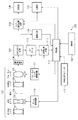
図1は、本発明の第1の実施形態に係る撮像装置の一例としてのデジタルビデオカメラ100の構成例を示すブロック図である。なお、本発明はデジタルスチルカメラを始めとして、顔検出機能及び動画撮影機能を有する他の任意の撮像装置及びそのような撮像装置を備える機器にも適用することができる。
Hereinafter, exemplary and preferred embodiments of the present invention will be described in detail with reference to the drawings.
(First embodiment)
FIG. 1 is a block diagram illustrating a configuration example of a
図1において、本実施形態のデジタルビデオカメラ100は、オートフォーカス機能を有するズームレンズ120を撮像光学系として備えている。ズームレンズ120は、第1固定レンズ101、光軸方向に移動して変倍を行う変倍レンズ102、絞り103、第2固定レンズ104及びフォーカスコンペンセータレンズ105を備える。フォーカスコンペンセータレンズ(以下、単にフォーカスレンズという)105は、変倍に伴う焦点面の移動を補正する機能とフォーカシングの機能とを兼ね備えている。
In FIG. 1, a
撮像素子106は、CCDセンサやCMOSセンサといった光電変換素子から構成される。CDS/AGC回路107は撮像素子106の出力を相関二重サンプリングするとともに、ゲイン調整する。
The
カメラ信号処理回路108は、CDS/AGC回路107からの出力信号に対して各種の画像処理を行い、映像信号を生成する。表示部109はLCD等により構成され、カメラ信号処理回路108からの映像信号を表示する。記録部115は、カメラ信号処理回路108からの映像信号を記録媒体(磁気テープ、光ディスク、半導体メモリ等)に記録する。
The camera
ズーム駆動回路110は、制御部114の制御に応じて変倍レンズ102を移動させる。フォーカスレンズ駆動回路111は制御部114の制御に応じてフォーカスレンズ105を移動させる。ズーム駆動回路110及びフォーカスレンズ駆動回路111は、ステッピングモータ、DCモータ、振動型モータ及びボイスコイルモータ等のアクチュエータにより構成される。
The
AFゲート112は、CDS/AGC回路107からの全画素の出力信号のうち、制御部114が設定した焦点検出に用いられる領域(焦点検出領域又はAF枠)の信号のみを後段のAF信号処理回路113に供給する。
The
AF信号処理回路113は、AFゲート112から供給される焦点検出領域中の画素信号に対して例えばフィルタを適用して予め定められた周波数帯域の成分、具体的には高周波成分を抽出し、AF評価値を生成する。
The AF
AF評価値は、制御部114に出力される。AF評価値は、撮像素子106からの出力信号に基づいて生成される映像の鮮鋭度(コントラストの大きさ)を表す値であるが、ピントが合った映像の鮮鋭度は高く、ぼけた映像の鮮鋭度は低いので、撮像光学系の焦点状態を表す値として利用できる。
The AF evaluation value is output to the
制御部114は例えばマイクロコンピュータであり、図示しないROMに予め記憶された制御プログラムを実行してデジタルビデオカメラ100の各部を制御することにより、デジタルビデオカメラ100全体の動作を司る。制御部114は、AF信号処理回路113から与えられるAF評価値に基づいて、フォーカスレンズ駆動回路111を制御してAF制御(自動合焦制御)動作を行う。また、後述する操作部118からのズーム指示に従って、ズーム駆動回路110を制御し、ズームレンズ120の倍率を変化させる。
The
顔検出部116は、CDS/AGC回路107が出力する画像信号に、公知の顔検出技術に基づく顔検出処理を適用し、画像内の人物領域の一例としての顔領域を検出する。公知の顔検出技術としては、ニューラルネットワークなどを利用した学習に基づく手法、テンプレートマッチングを用いて目、鼻、口等の形状に特徴のある部位を画像から探し出し、類似度が高ければ顔とみなす手法などがある。また、他にも、肌の色や目の形といった画像特徴量を検出し、統計的解析を用いた手法等、多数提案されている。一般的にはこれらの手法を複数組み合わせ、顔検出の精度を向上させている。具体的な例としては特開2002−251380号公報に記載のウェーブレット変換と画像特徴量を利用して顔検出する方法などが挙げられる。
The
顔検出部116は、例えば人物の顔として検出された領域(顔領域)の位置と大きさをを画像内で特定可能な情報を、顔検出結果として制御部114に出力する。顔領域の位置を特定可能な情報としては、顔領域の中心位置や、目、鼻、口等の顔の特徴点の位置でも良い。制御部114は、この顔検出結果に基づき、画像内の顔領域を含む領域に焦点検出領域を設定するよう、AFゲート112へ指示する。
The
外部測距ユニット117は、ズームレンズ120を通過した光を用いずに、被写体距離に関する情報の測定(焦点ずれ量及びその方向の検出)を行う。外部測距ユニット117は、測定した焦点ずれ量及びずれの方向から被写体距離を求め、被写体距離を測定結果として出力しても良い。
The external
外部測距ユニット117は、外測位相差検出方式、超音波センサ方式、赤外線センサ方式等、任意の方式を採用しうるが、本実施形態においては外側位相差検出方式を用いているものとする。外部測距ユニット117による測距情報(被写体距離、又は焦点ずれ量及びずれ方向)および測距信頼性情報は制御部114へ供給され、フォーカスレンズ位置へと変換される。測距信頼性情報は、外部測距ユニット117の測距方式に応じて定めることができる。例えば、被写体からの光束を2分割し、2分割した光束を1組のラインセンサに受光させて得られる1組の信号波形の位相差を用いて測距する外測位相差検出方式であれば、1組の信号波形の相関性を測距信頼性情報として用いることができる。
The external
操作部118は、撮影者がデジタルビデオカメラ100に各種指示や設定を入力するためのスイッチ、ボタン、ダイヤル等の入力デバイス群である。撮影開始/一時停止ボタン、ズームスイッチ、静止画撮影ボタン、方向ボタン、メニューボタン、実行ボタンなどが操作部118に含まれる。
The
次に、制御部114が行うAF制御の詳細について、図2に示すフローチャートを用いて説明する。図2に示すAF制御動作は、例えば1フィールドの画像を生成するための、撮像素子106からの撮像信号の読み出し周期で繰り返し実行される。
Next, details of the AF control performed by the
なお、表示部109を電子ビューファインダ(EVF)として機能させるため、所定のフレームレート(例えば30フレーム/秒)で撮影と表示が繰り返されているものとする。この場合、処理負荷を軽減するため、表示部109での表示用に、撮像素子106よりも少ない画素数の画像(表示用画像)を生成するのが一般的である。本実施形態においても、表示用画像を生成し、顔検出部116は表示用画像に対して顔検出を行うものとするが、顔検出は表示用画像よりも画素数の多い画像に対して行うように構成しても良い。なお、顔検出部116による顔検出は、表示用画像の各フレームに対して実行しても良いし、所定フレーム数おきに実行してもよい。
In order to cause the
S202で制御部114は、外部測距ユニット117から測距情報を取得し、被写体距離、または焦点ずれ量とその方向からフォーカスレンズ105の目標位置を算出する。
In step S202, the
S203で制御部114は、顔検出部116から顔検出結果を取得し、検出された顔の有無を判定する。S204で制御部114は、検出された顔があれば顔検出が成功したものと判定し、処理をS205へ進める。また制御部114は、検出された顔が無ければ顔検出が失敗したと判定し、処理をS208へ進める。
In S203, the
S205で制御部114は、顔検出が成功したことを受けて、顔検出部116から取得した顔検出結果に基づいて、AFゲート112に、検出された顔領域に対して焦点検出領域(AF枠)を設定する。顔領域に対して設定されるAF枠を、以下、単に顔枠と呼ぶ。顔枠は対応する顔領域に追従して移動する。また、顔枠の大きさは顔領域と同一で無くても良く、例えば、顔領域に外接する方形領域や、この方形領域に含まれる方形領域として設定することができる。
In step S <b> 205, the
次に、S206で制御部114は、顔枠に対するAF評価値を取得する。そして、S207で制御部114は、顔検出が成功している状態を表すフラグ(以下、単に顔検出中フラグという)をセットする。顔検出フラグは例えば制御部114が保持する1ビットデータであり、1がセット、0がリセット(セットされていない)状態を表すものとする。
S217で制御部114は、S206、S213又はS215で、設定中のAF枠から取得したAF評価値を保存する。保存するAF評価値は最新のものだけでなく、過去の所定回数分について保存し、履歴を残しておく。
Next, in S206, the
In S217, the
S218で制御部114は、S202で算出したフォーカスレンズ位置を保存する。保存するフォーカスレンズ位置は最新のものだけでなく、過去の所定回数分について保存し、履歴を残しておく。
In step S218, the
そして、S219で制御部114は、S217で保存したAF評価値を用いたTV−AF制御と、S218で保存したフォーカスレンズ位置を用いた、外部測距ユニット117による測距情報に基づくAF制御(外測AF制御)とを組み合わせた焦点検出を実行する。
In step S219, the
ここで、TV−AF制御は、上述のように、フォーカスレンズ105の位置を変えながらコントラストの程度を示すAF評価値を求め、AF評価値が最大となるフォーカスレンズ105の位置を合焦位置として探索するものである。
Here, in the TV-AF control, as described above, an AF evaluation value indicating the degree of contrast is obtained while changing the position of the
また、TV−AF制御には、合焦が得られている状態において、フォーカスレンズ105を再駆動する必要性を判断するためにAF評価値の変化を判定する処理など、合焦状態を維持するための処理も含まれる。
In the TV-AF control, in-focus state is maintained, such as processing for determining a change in AF evaluation value to determine the necessity of re-driving the
一方、外測AF制御は、S202で算出したフォーカスレンズ位置へ、フォーカスレンズ105を移動させるものである。
On the other hand, the external measurement AF control is to move the
TV−AF制御と外測AF制御をどのように組み合わせて焦点検出を行うかについて、本発明では特に制限されない。例えば、合焦状態に近い場合には、TV−AF制御を用いて高精度な安定した焦点検出を行う。また、合焦状態に遠く、被写体が大きくボケている場合には、外測AF制御によりフォーカスレンズ105を合焦位置の近傍まで高速に移動させたのち、TV−AF制御に切り替える、などが考えられる。これは、あくまで一例であり、公知の任意の方法により両者を組み合わせることができる。
In the present invention, the combination of the TV-AF control and the external measurement AF control to perform focus detection is not particularly limited. For example, when close to the in-focus state, highly accurate and stable focus detection is performed using TV-AF control. If the subject is far out of focus and the subject is greatly blurred, it is possible to move the
一方、S204で顔検出が失敗であると判定された場合、S208で制御部114は検出中フラグがセットされているか判定する。
主被写体、即ち本実施形態では人物の顔、が認識できない場合、主被写体にAF枠を設定することは困難である。制御部114は、顔検出中フラグがセットされていない場合、現在の撮影シーンには、人物の被写体が存在しない可能性が大きいと判断する。この場合、制御部114は、S214で、通常、撮影者は撮影したい被写体を画面中央に配置することが多いことを考慮し、画面中央を固定中心とした焦点検出領域(以下、通常枠と呼ぶ)をAFゲート112に設定する。
On the other hand, if it is determined in S204 that face detection has failed, the
If the main subject, that is, the face of a person in this embodiment cannot be recognized, it is difficult to set an AF frame on the main subject. When the face detection flag is not set, the
次に、制御部114は、S215で通常枠からAF評価値を取得し、S216で顔検出中フラグをクリアして、S217以降は上述した処理を行う。つまり、顔が検出されず、かつ、顔検出中フラグがクリアされている場合、S219におけるTV−AF制御は、通常枠に対して実施される。
Next, the
S208で顔検出中フラグがセットされていると判定された場合、制御部114は、S209で、S202で算出した、外部測距ユニット117の測定結果に基づくフォーカスレンズ位置の前回の値と今回の値の差の比較しきい値を算出する。
If it is determined in S208 that the face detection flag is set, the
そして、S210で制御部114は、S218で保存した、外部測距ユニット117の測定結果に基づくフォーカスレンズ位置の前回の値と今回の値との差(変化量)を、S209で算出した比較しきい値と比較する。
Then, in S210, the
そして、S211で制御部114は、フォーカスレンズ位置の変化量がS209で算出した比較しきい値よりも大きいか否かを判別する。差がしきい値よりも大きい場合、撮影しているシーンから主被写体が存在しなくなったと判定する。この場合、制御部114は処理をS214に移行させ、顔検出フラグがセットされていない場合と同様に、通常枠を焦点検出領域として設定する。
In step S211, the
一方、外部測距ユニット117の測定結果に基づくフォーカスレンズ位置の変化量がS209で算出した比較しきい値以下の場合、制御部114は、主被写体は撮影シーン内に存在しているが、一時的に検出できなくなったと判断する。例えば、主被写体が横を向いたり、目を閉じてしまったり、他の被写体が主被写体の前を横切ったことにより顔が認識できなくなった場合には、このような状態となりうる。
On the other hand, when the change amount of the focus lens position based on the measurement result of the external
この場合、制御部114は、焦点検出領域の設定を変更しない。すなわち、現在設定されている顔枠を用いてTV−AF制御を行う。S212で制御部114は、S205と同様に、前回と同じ位置に顔枠と通常枠を設定する。そして、S213で制御部114は、S206と同様に、顔枠のAF評価値を取得する。以後、S217以降の処理を行い、上述した通りTV−AF制御と外測AF制御を組み合わせた焦点検出を行う。
In this case, the
このように、顔検出フラグがセットされている場合には、外部測距ユニット117の測定結果に基づくフォーカスレンズ位置の差に基づいて、主被写体(人物被写体)が撮像シーン内にまだ存在しているか、もう存在していないかを判断する。これは、例えば、現時点では顔の検出に失敗したが、その前は顔が検出できていた場合、合焦位置に大きな変化がなければ、依然として主被写体が存在する可能性が高く、一時的に顔が検出できなくなったと判断できるからである。逆に、主被写体が撮影シーン外に移動した場合には、外部測距ユニット117による測距情報に基づいて算出されるフォーカスレンズ位置が大きく変化するであろう。
As described above, when the face detection flag is set, the main subject (person subject) is still present in the imaging scene based on the difference in the focus lens position based on the measurement result of the external
従って、S209で算出する比較しきい値は、主被写体が依然として存在するかどうかの判断に適した値として、経験的に求めた固定値であっても良い。あるいは、ズームレンズ120の焦点距離(画角)に応じて変更してもよい。これは、焦点距離が短いワイド側と焦点距離が長いテレ側を比較した場合、テレ側になればなるほど、手ぶれの影響が増え、フォーカスレンズ位置のばらつきが大きくなる可能性があるためである。よって、焦点距離が長くなるにつれて、比較しきい値が大きくなるように算出しても良い。
Therefore, the comparison threshold value calculated in S209 may be a fixed value obtained empirically as a value suitable for determining whether or not the main subject still exists. Alternatively, the
また、被写体距離や、焦点ずれ量及びその方向など、主被写体の距離を表す情報であれば、フォーカスレンズ位置に代えてS209、S210、S211の処理に用いることができる。 In addition, information representing the distance of the main subject, such as the subject distance, defocus amount, and direction thereof, can be used for the processing of S209, S210, and S211 instead of the focus lens position.
外部測距ユニット117が外測位相差検出方式により、かつ、フォーカスレンズ位置の代わりに被写体距離の比較を行う場合、被写体距離が大きい(無限大に近い)場合の比較しきい値を大きく算出することができる。これは、位相差検出方式の方式上、被写体距離が無限大に近い場合、被写体距離のばらつきが大きくなってしまうからである。
When the external
以上説明したように、本実施形態によれば、人物の顔が検出された場合には、顔領域に対してAF枠を設定するので、人物に安定したピント合わせを行うことが可能である。 As described above, according to the present embodiment, when a person's face is detected, an AF frame is set for the face area, and thus it is possible to perform stable focusing on the person.
さらに、顔検出できた状態からできない状態になっても、外部測距ユニットを用いて得られる被写体距離に関する情報の変化量が予め定めた値以下であれば、AF枠を顔領域に設定したまま変更しない。そのため、人物被写体が横を向いたなどの理由により一時的に顔検出に失敗した場合においても焦点検出領域が切り替わる従来技術よりも、自動合焦制御の安定性を改善することができる。 Furthermore, even if the face can be detected, the AF frame remains set as the face area if the amount of change in the information about the subject distance obtained using the external distance measuring unit is not more than a predetermined value. It does not change. Therefore, it is possible to improve the stability of the automatic focusing control over the conventional technique in which the focus detection area is switched even when face detection temporarily fails due to a person subject facing sideways.
(第2の実施形態)
次に、本発明の第2の実施形態について説明する。
本実施形態に係る撮像装置は、AF制御動作を除いて第1の実施形態と同様でよい。従って、AF制御動作についてのみ説明する。
(Second Embodiment)
Next, a second embodiment of the present invention will be described.
The imaging apparatus according to the present embodiment may be the same as that of the first embodiment except for the AF control operation. Therefore, only the AF control operation will be described.
図3は、本実施形態の撮像装置におけるAF制御動作を説明するためのフローチャートである。図3において、第1の実施形態で説明した動作と同じ動作を行うステップについては、同じ参照数字を付して説明を省略する。 FIG. 3 is a flowchart for explaining the AF control operation in the imaging apparatus of the present embodiment. In FIG. 3, steps that perform the same operations as those described in the first embodiment are denoted by the same reference numerals and description thereof is omitted.
図3に示すように、本実施形態のAF制御動作は、第1の実施形態のAF制御動作(図2)と、顔が検出できていた状態から検出できない状態になった場合(S208、YES)に、それが一時的なものであるか否かを判定する方法において異なる。あるいは、顔が検出できていた状態から検出できない状態になった場合に、依然として撮影シーン内に主被写体が存在する可能性が高いか否かを判定する方法において異なるとも言える。 As shown in FIG. 3, the AF control operation of the present embodiment is the same as the AF control operation of the first embodiment (FIG. 2), when the face is detected and becomes undetectable (S208, YES). ) Differ in the method of determining whether or not it is temporary. Alternatively, it can be said that the method for determining whether or not there is a high possibility that the main subject is still present in the shooting scene when the face has been detected and becomes undetectable is different.
具体的には、現在のフォーカスレンズ位置と、外部測距ユニット117の現在の測距情報に基づくフォーカスレンズ位置の差が比較しきい値より大きいか否かにより、依然として撮影シーン内に主被写体が存在する可能性が高いか否かを判定する。
Specifically, depending on whether or not the difference between the current focus lens position and the focus lens position based on the current distance measurement information of the external
すなわち、S208で、顔検出中フラグがセットされていると判定された場合、制御部114は処理をS309へ進める。
That is, when it is determined in S208 that the face detection flag is set, the
S309で制御部114は、現在のフォーカスレンズ位置と、S202で外部測距ユニット117による測距情報に基づいて算出したフォーカスレンズ位置との差と比較するための比較しきい値を算出する。現在のフォーカスレンズ位置とは、S219の制御結果によるフォーカスレンズ位置である。
In S309, the
そして、S310で制御部114は、現在のフォーカスレンズ位置と、S202で外部測距ユニット117による測距情報に基づいて算出したフォーカスレンズ位置との差を比較する。
In step S310, the
S211で、制御部114は、現在のフォーカスレンズ位置とS202で算出したフォーカスレンズ位置との差が、S309で算出した比較しきい値よりも大きいか否かを判別する。差がしきい値よりも大きい場合には、主被写体が存在しなくなったと判定する。そして、制御部114は処理をS214に進め、焦点検出領域として通常枠を設定する。
In S211, the
一方、現在のフォーカスレンズ位置とS202で算出したフォーカスレンズ位置との差が、S309で算出した比較しきい値以下の場合、制御部114は一時的に顔検出に失敗したものと判断し、焦点検出領域を変更せず、前回と同様の顔枠を設定する。例えば、主被写体が横を向いたり、目を閉じてしまったり、他の被写体が主被写体の前を横切ったことにより顔が認識できなくなった場合には、このような状態となりうる。
On the other hand, if the difference between the current focus lens position and the focus lens position calculated in S202 is equal to or smaller than the comparison threshold value calculated in S309, the
なお、本実施形態において、現在のフォーカスレンズ位置と、S202で外部測距ユニット117による測距情報に基づいて算出したフォーカスレンズ位置との差を比較するのは、外部測距ユニット117の測距精度が低い場合があるからである。
In this embodiment, the difference between the current focus lens position and the focus lens position calculated based on the distance measurement information by the external
外部測距ユニット117の測距精度が低い場合、被写体距離やフォーカスレンズ位置が常に取得できるとは限らない。そのため、前回外部測距ユニット117による測距情報から算出したフォーカスレンズ位置が、顔検出された主被写体に焦点を合わせていたわけではない場合もある。
When the distance measuring accuracy of the external
また、顔検出できている期間には外部測距ユニット117で測距できず、顔検出ができなくなってから測距できる場合もある。このような場合には、第1の実施形態のような、外部測距ユニット117による測距情報に基づいて算出したフォーカスレンズ位置の差に基づく判断は精度が低下する。
In some cases, the distance cannot be measured by the external
そのため、本実施形態では、顔検出ができる状態からできない状態になった場合、現在のフォーカスレンズ位置と、外部測距ユニット117による測距情報に基づく最新のフォーカスレンズ位置とを比較する。これにより、外部測距ユニット117の測距精度が低い場合においても、主被写体が存在するか、存在していないかの判断が容易となり、主被写体が存在しなくなった場合に、新たな主被写体に対する焦点検出をすばやく行うことが可能となる。
For this reason, in the present embodiment, when the face detection state is changed to the non-face detection state, the current focus lens position is compared with the latest focus lens position based on the distance measurement information by the external
(第3の実施形態)
次に、本発明の第3の実施形態について説明する。
本実施形態に係る撮像装置は、AF制御動作を除いて第1の実施形態と同様でよい。従って、AF制御動作についてのみ説明する。
(Third embodiment)
Next, a third embodiment of the present invention will be described.
The imaging apparatus according to the present embodiment may be the same as that of the first embodiment except for the AF control operation. Therefore, only the AF control operation will be described.
図4は、本実施形態の撮像装置におけるAF制御動作を説明するためのフローチャートである。図4において、第1及び第2の実施形態で説明した動作と同じ動作を行うステップについては、同じ参照数字を付して説明を省略する。 FIG. 4 is a flowchart for explaining an AF control operation in the imaging apparatus of the present embodiment. In FIG. 4, steps that perform the same operations as those described in the first and second embodiments are denoted by the same reference numerals and description thereof is omitted.
図4に示すように、本実施形態のAF制御動作は、顔が検出された場合には、焦点検出領域として、顔枠と通常枠の両方をAFゲート112に設定することを特徴とする。
As shown in FIG. 4, the AF control operation of the present embodiment is characterized in that both a face frame and a normal frame are set in the
具体的には、S204で制御部114が、顔検出に成功していると判定した場合、S420において、制御部114は、焦点検出領域として顔枠と通常枠の両方をAFゲート112に設定する。
Specifically, when the
上述のように、顔枠は、顔検出部116が検出した顔領域に対して設定される焦点検出領域であり、対応する顔領域の検出位置が変化するとそれに追従して位置が変化する。一方、通常枠は、被写体によらずその中央位置(本実施形態では画面中央)が固定されている。なお、本実施形態において、通常枠は顔枠よりも大きく、かつ顔枠を含むように設定する。また、通常枠は2つ以上設定しても良い。この場合、少なくとも1つの通常枠が顔枠を含むような大きさに設定する。
As described above, the face frame is a focus detection area set for the face area detected by the
S421で制御部114は、AF信号処理回路113を通じて、顔枠と通常枠から各々AF評価値を取得する。S207で制御部114は、顔検出中フラグをセットする。
In step S <b> 421, the
S217で制御部114は、設定中のAF枠から取得したAF評価値を保存する。保存するAF評価値は最新のものだけでなく、過去の所定回数分について保存し、履歴を残しておく。
In S217, the
S218で制御部114は、S202で算出したフォーカスレンズ位置(外部測距ユニット117による測距情報に基づくフォーカスレンズ位置)を保存する。保存するフォーカスレンズ位置は最新のものだけでなく、過去の所定回数分について保存し、履歴を残しておく。
In step S218, the
そして、S424で制御部114は、設定されているAF枠から取得した各AF評価値を加算し、TV−AF制御により合焦制御する場合に主として用いるAF評価値を生成する。
In step S424, the
ここで、撮影者が意図する被写体が人物である可能性が高いことを考慮して、顔枠と通常枠の両方からAF評価値が得られている場合には、顔枠から得られたAF評価値に、通常枠から得られたAF評価値よりも重み付けして加算しても良い。また、顔枠が設定された顔領域の画像中の位置に応じて重みを変更してもよい。例えば、主被写体は画面中央に配置されることが多い点を考慮して、顔領域が画面中央付近にある場合には、重みを大きくし、画面の端にある場合には、重みを小さくすることができる。 Here, in consideration of the high possibility that the subject intended by the photographer is a person, when AF evaluation values are obtained from both the face frame and the normal frame, the AF obtained from the face frame The evaluation value may be weighted and added to the AF evaluation value obtained from the normal frame. Further, the weight may be changed according to the position in the image of the face area where the face frame is set. For example, considering that the main subject is often placed in the center of the screen, the weight is increased when the face area is near the center of the screen, and the weight is decreased when the face area is at the edge of the screen. be able to.
特に動画撮影時には、撮影中に主被写体とは違う被写体が撮影範囲に入ってくることも多くなることが想定される。その場合、顔枠のAF評価値の重みを固定すると、画面の端に位置する、撮影を意図しない人物の顔に合焦しようとして、一時的にピント合わせが不安定になる可能性がある。
S219で制御部114は、TV−AF制御と外測AF制御とを組み合わせたAF制御を実行する。
In particular, during movie shooting, it is assumed that a subject different from the main subject often enters the shooting range during shooting. In this case, if the weight of the AF evaluation value of the face frame is fixed, there is a possibility that focusing is temporarily unstable in an attempt to focus on the face of a person who is located at the edge of the screen and is not intended for shooting.
In S219, the
一方、顔認識が失敗した場合S208へ進み、顔検出中フラグがセットされているかを判定する。顔検出中フラグがセットされていない場合、制御部114は第1の実施形態と同様にS214〜S216の処理を実行する。これにより、通常枠からのAF評価値のみが得られる。
On the other hand, if the face recognition fails, the process proceeds to S208, and it is determined whether the face detection flag is set. When the face detection flag is not set, the
S208で、顔検出中フラグがセットされている場合、制御部114は、第1及び第2の実施形態で説明したS309、S310、S211の処理を実行する。
When the face detection flag is set in S208, the
S211において、制御部114は、現在のフォーカスレンズ位置とS202で算出したフォーカスレンズ位置との差が、S309で算出した比較しきい値よりも大きい場合には、主被写体が存在しなくなったと判定する。そして、制御部114は処理をS214に進め、焦点検出領域として通常枠を設定する。
In S211, the
一方、現在のフォーカスレンズ位置とS202で算出したフォーカスレンズ位置との差が、S309で算出した比較しきい値以下の場合、制御部114は一時的に顔検出に失敗したものと判断する。
On the other hand, if the difference between the current focus lens position and the focus lens position calculated in S202 is equal to or smaller than the comparison threshold value calculated in S309, the
そして、S422で制御部114は、S420と同様に、前回と同じ位置に顔枠と通常枠を設定し、S423で、S421と同様に、顔枠と通常枠の各々におけるAF評価値を取得する。
Then, in S422, the
ここで、本実施形態におけるAF枠の設定例について、図5を用いて説明する。
図5(a)は、顔枠と通常枠の両方を設定する場合の例を、(b)は通常枠のみを設定する場合の例をそれぞれ示している。
図5(a)に示すように、通常枠51は顔枠55よりも大きく、顔枠55を含むように画面中央に設定される。通常枠51は、被写体を特定しないでAF評価値を得るために、画面の広範囲を占めるように設定される。
Here, an example of setting the AF frame in the present embodiment will be described with reference to FIG.
FIG. 5A shows an example of setting both the face frame and the normal frame, and FIG. 5B shows an example of setting only the normal frame.
As shown in FIG. 5A, the
一方、顔枠を設定せず、通常枠のみ設定する場合には、図5(a)と同様の通常枠51を設定することもできる。しかし、撮影者が画面中央に意図した被写体を配置して撮影することが多いことを考慮し、図5(b)に示すように、通常枠51よりも小さい通常枠52を設定しても良い。通常枠52も、通常枠51と同様、枠の中心は画面中心と共通である。また、通常枠52のみではなく、通常枠51と通常枠52の両方を設定することもできる。
On the other hand, when only a normal frame is set without setting a face frame, a
以上説明したように、本実施形態によれば、顔検出できている場合と、一時的に顔検出できなくなっていると判断される場合には、顔枠と通常枠の両方にAF枠を設定し、両方の枠から得られたAF評価値に基づいて合焦制御を行う。そのため、第2の実施形態と同様の効果に加え、顔領域以外の情報も加味した合焦制御により、意図しない人物に対して合焦させてしまう可能性を抑制することができる。 As described above, according to the present embodiment, when a face can be detected or when it is determined that a face cannot be detected temporarily, AF frames are set for both the face frame and the normal frame. Then, focusing control is performed based on the AF evaluation values obtained from both frames. Therefore, in addition to the same effects as those of the second embodiment, the possibility of focusing on an unintended person can be suppressed by focusing control that includes information other than the face area.
(第4の実施形態)
次に、本発明の第4の実施形態について説明する。
図6は、本発明の第4の実施形態に係る撮像装置の一例としてのデジタルビデオカメラ100’の構成例を示すブロック図である。図6において、第1の実施形態のデジタルビデオカメラ100と共通する構成要素については図1と同じ参照数字を付し、重複する説明を省略する。
(Fourth embodiment)
Next, a fourth embodiment of the present invention will be described.
FIG. 6 is a block diagram illustrating a configuration example of a
本実施形態に係る撮像装置は、外部測距ユニット117の代わりに、TTL方式の測距(内部測距)を行うための構成を有している点で第1の実施形態のデジタルビデオカメラ100と異なる。
The image pickup apparatus according to the present embodiment has a configuration for performing TTL distance measurement (internal distance measurement) instead of the external
そのため、本実施形態のデジタルビデオカメラ100’は、ズームレンズ120が被写体側から順に、第1固定レンズ101、変倍レンズ102、フォーカスレンズ105、ハーフプリズム621、絞り103及び第2固定レンズ121とにより構成されている。
Therefore, in the
ハーフプリズム621は、フォーカスレンズ105から絞り103に向かう光束を、撮像素子106に向かう光束成分と、後述するAFセンサ624に向かう光束成分とに分割する。絞り103は、動画撮影中、常に動作しているので、絞り103よりも被写体側に配置したハーフプリズム621によって、入射光束を分割する。
The
サブミラー622は、ハーフプリズム621により分割された光束成分を反射し、光路の方向を変更する。結像レンズ623は、サブミラー622が反射した光束をAFセンサ624上に結像させる。AFセンサ624は、本実施形態では位相差検出方式AF用の一対の受光素子列(ラインセンサ)を有する。AF回路625は、AFセンサ624の一対のラインセンサから出力される一対の像信号の位相差から、被写体距離、又はピントずれ量及びずれ方向、を測距情報として演算する。
The
サブミラー622、結像レンズ623、AFセンサ624及びAF回路625は、内測位相差検出方式の測距ユニット(内部測距ユニット)を形成する。
The
このように構成されたビデオカメラでは、外部測距ユニット117に代えて、AF回路625から測距情報を得ること第1〜第3の実施形態で説明したAF制御動作(図2〜図4)と同様のAF制御動作を行うことができる。ここで、測距情報はピントずれ量及びずれ方向であってよい。
In the video camera configured as described above, the AF control operation described in the first to third embodiments for obtaining distance measurement information from the
例えば、S202で、制御部114は、AF回路625からの測距情報に基づいて、フォーカスレンズ105の合焦位置(内測合焦位置)を算出する。
また、S210で制御部114は、AF回路625の測距情報に基づくフォーカスレンズ位置もしくは被写体距離について、前回と今回との変化量を算出し、これを比較しきい値と比較する。
For example, in S <b> 202, the
In S210, the
また、S219において、制御部114は、TV−AF制御と内部測距ユニットによる測距情報に基づくAF制御(内測AF制御)とを組み合わせたAF制御を実行する。
あるいは、S310で制御部114は、現在のフォーカスレンズ位置と、AF回路625からの測距情報に基づくフォーカスレンズ位置との差が、比較しきい値より大きいか否かを判別する。
In S219, the
Alternatively, in S310, the
このように、本実施形態によっても、第1乃至第3の実施形態と同様の効果を達成することが可能である。 Thus, the present embodiment can achieve the same effects as those of the first to third embodiments.
(他の実施形態)
なお、上述の実施形態は組み合わせて用いることも可能である。例えば、第3の実施形態を第1の実施形態に適用してもよい。
また、上述の実施形態においては、TV−AF制御と外測(又は内測)AF制御とを組み合わせて合焦制御を行うものとして説明した。しかし、本発明はこのような複数のAF制御を必須とするものではなく、例えばTV−AF制御のみを用いて合焦制御を行っても良い。
(Other embodiments)
The above-described embodiments can be used in combination. For example, the third embodiment may be applied to the first embodiment.
In the above-described embodiment, the focus control is described by combining the TV-AF control and the external measurement (or internal measurement) AF control. However, the present invention does not require such a plurality of AF controls, and focus control may be performed using only TV-AF control, for example.
Claims (10)
被写体の距離に対応する情報を測定する測距手段と、
撮像された画像から、人物の顔の領域を顔領域として検出する検出手段と、
前記画像に対する焦点検出領域を設定する設定手段と、
前記画像の前記焦点検出領域に含まれる、予め定められた周波数帯域の成分に基づいてAF評価値を生成する生成手段と、
前記生成手段が生成したAF評価値に基づいて、前記フォーカスレンズを移動させて焦点検出を行う制御手段とを有し、
前記設定手段は、
前記顔領域が検出されている場合には、前記顔領域に対して焦点検出領域を設定し、
前記顔領域が検出されていた状態から前記顔領域が検出されない状態になった場合には、前記測距手段により検出された前記顔領域が検出されていた状態における前記被写体の距離と、前記顔領域が検出されない状態における前記被写体の距離との変化量が予め定めたしきい値以下であれば、前記顔領域が検出されていた状態において設定されていた焦点検出領域を変更せず、前記変化量が予め定められたしきい値より大きければ、前記画像内の予め定められた領域に焦点検出領域を変更することを特徴とする撮像装置。 An imaging apparatus that performs automatic focusing control by moving a focus lens,
Ranging means for measuring information corresponding to the distance of the subject;
Detecting means for detecting a face area of a person as a face area from a captured image;
Setting means for setting a focus detection area for the image;
Generating means for generating an AF evaluation value based on a predetermined frequency band component included in the focus detection region of the image;
Control means for performing focus detection by moving the focus lens based on the AF evaluation value generated by the generation means;
The setting means includes
When the face area is detected, a focus detection area is set for the face area,
When the face area is not detected from the state in which the face area is detected, the distance of the subject in the state in which the face area detected by the distance measuring unit is detected, and the face if less than the threshold amount of change in the distance of the object in the state in which the region is not detected is set Me pre, without changing the focus detection area has been set in a state in which the face area has been detected, the An imaging apparatus characterized by changing a focus detection area to a predetermined area in the image if the amount of change is larger than a predetermined threshold.
前記顔領域が検出されていた状態から前記顔領域が検出されない状態になった場合には、前記顔領域が検出されていた状態における前記測距手段の測定結果と、前記顔領域が検出されない状態における前記測距手段の測定結果とを用いて、前記被写体の距離の変化量を求めることを特徴とする請求項1記載の撮像装置。 The setting means includes
When the face area is not detected from the state in which the face area is detected, the measurement result of the distance measuring means in the state in which the face area is detected, and the state in which the face area is not detected The image pickup apparatus according to claim 1, wherein a change amount of the distance of the subject is obtained using a measurement result of the distance measuring means.
前記顔領域が検出されていた状態から前記顔領域が検出されない状態になった場合には、前記顔領域が検出されていた状態における前記測距手段の測定結果から算出されるフォーカスレンズの位置と、現在の前記フォーカスレンズの位置との差を、前記被写体の距離の変化量として求めることを特徴とする請求項1記載の撮像装置。 The setting means includes
When the face area is not detected from the state where the face area is detected, the position of the focus lens calculated from the measurement result of the distance measuring means in the state where the face area is detected; The imaging apparatus according to claim 1, wherein a difference from the current position of the focus lens is obtained as a change amount of the distance of the subject.
前記顔領域が検出されている場合に、前記顔領域に加えて、前記予め定められた領域に対しても焦点検出領域を設定することを特徴とする請求項1乃至請求項3のいずれか1項に記載の撮像装置。 The setting means is
The focus detection area is set for the predetermined area in addition to the face area when the face area is detected. The imaging device according to item.
被写体の距離に対応する情報を測定する測距手段と、 Ranging means for measuring information corresponding to the distance of the subject;
撮像された画像から、人物の顔の領域を顔領域として検出する検出手段と、 Detecting means for detecting a face area of a person as a face area from a captured image;
前記画像に対する焦点検出領域を設定する設定手段と、 Setting means for setting a focus detection area for the image;
前記画像の前記焦点検出領域に含まれる、予め定められた周波数帯域の成分に基づいてAF評価値を生成する生成手段と、 Generating means for generating an AF evaluation value based on a predetermined frequency band component included in the focus detection region of the image;
前記生成手段が生成したAF評価値に基づいて、前記フォーカスレンズを移動させて焦点検出を行う制御手段とを有し、 Control means for performing focus detection by moving the focus lens based on the AF evaluation value generated by the generation means;
前記制御手段は、 The control means includes
前記顔領域が検出されている場合には、前記顔領域に対して設定された焦点検出領域におけるAF評価値に基づいて前記フォーカスレンズを移動させ、 When the face area is detected, the focus lens is moved based on the AF evaluation value in the focus detection area set for the face area,
前記顔領域が検出されていた状態から前記顔領域が検出されない状態になった場合には、前記測距手段により検出された前記顔領域が検出されていた状態における前記被写体の距離と、前記顔領域が検出されない状態における前記被写体の距離との変化量が前記変化量が予め定めたしきい値以下であれば、前記フォーカスレンズを移動させないことを特徴とする撮像装置。 When the face area is not detected from the state in which the face area is detected, the distance of the subject in the state in which the face area detected by the distance measuring unit is detected, and the face An imaging apparatus, wherein the focus lens is not moved when the amount of change from the distance of the subject in a state where no region is detected is equal to or less than a predetermined threshold value.
測距手段が、被写体の距離に対応する情報を測定する測距ステップと、
検出手段が、撮像された画像から、人物の顔の領域を顔領域として検出する検出ステップと、
設定手段が、前記画像に対する焦点検出領域を設定する設定ステップと、
生成手段が、前記画像の前記焦点検出領域に含まれる、予め定められた周波数帯域の成分に基づいてAF評価値を生成する生成ステップと、
制御手段が、前記生成ステップで生成されたAF評価値に基づいて、前記フォーカスレンズを移動させて焦点検出を行う制御ステップとを有し、
前記設定ステップでは、
前記顔領域が検出されている場合には、前記顔領域に対して焦点検出領域を設定し、
前記顔領域が検出されていた状態から前記顔領域が検出されない状態になった場合には、前記測距ステップにおいて検出された前記顔領域が検出されていた状態における前記被写体の距離と、前記顔領域が検出されない状態における前記被写体の距離との変化量が予め定めたしきい値以下であれば、前記顔領域が検出されていた状態において設定されていた焦点検出領域を変更せず、前記変化量が予め定められたしきい値より大きければ、前記画像内の予め定められた領域に焦点検出領域を変更することを特徴とする撮像装置の制御方法。 A method of controlling an imaging apparatus that performs automatic focusing control by moving a focus lens,
A distance measuring step in which the distance measuring means measures information corresponding to the distance of the subject;
A detection step in which the detection means detects a human face area as a face area from the captured image;
A setting step of setting means sets the focus detection area for the image,
Generating means, said included in the focus detection area of the image, a generation step of generating an AF evaluation value based on the component of the predetermined frequency band,
And a control unit that performs focus detection by moving the focus lens based on the AF evaluation value generated in the generation step,
In the setting step,
When the face area is detected, a focus detection area is set for the face area,
When the face area from the state in which the face area has been detected is ready is not detected, the distance of the object in a state in which the face area detected by have you to the distance measuring step has been detected, if the face area change amount is equal to or less than a predetermined threshold value of the distance of the object in a state that is not detected, without changing the focus detection area has been set in a state in which the face area has been detected If the amount of change is larger than a predetermined threshold value, the focus detection area is changed to a predetermined area in the image.
測距手段が、被写体の距離に対応する情報を測定する測距ステップと、 A distance measuring step in which the distance measuring means measures information corresponding to the distance of the subject;
検出手段が、撮像された画像から、人物の顔の領域を顔領域として検出する検出ステップと、 A detection step in which the detection means detects a human face area as a face area from the captured image;
設定手段が、前記画像に対する焦点検出領域を設定する設定ステップと、 A setting step for setting a focus detection area for the image;
生成手段が、前記画像の前記焦点検出領域に含まれる、予め定められた周波数帯域の成分に基づいてAF評価値を生成する生成ステップと、 A generating step for generating an AF evaluation value based on a predetermined frequency band component included in the focus detection region of the image;
制御手段が、前記生成ステップで生成されたAF評価値に基づいて、前記フォーカスレンズを移動させて焦点検出を行う制御ステップとを有し、 And a control unit that performs focus detection by moving the focus lens based on the AF evaluation value generated in the generation step,
前記制御ステップでは、 In the control step,
前記顔領域が検出されている場合には、前記顔領域に対して設定された焦点検出領域におけるAF評価値に基づいて前記フォーカスレンズを移動させ、 When the face area is detected, the focus lens is moved based on the AF evaluation value in the focus detection area set for the face area,
前記顔領域が検出されていた状態から前記顔領域が検出されない状態になった場合には、前記測距ステップにより検出された前記顔領域が検出されていた状態における前記被写体の距離と、前記顔領域が検出されない状態における前記被写体の距離との変化量が予め定めたしきい値以下であれば、前記フォーカスレンズを移動させないことを特徴とする撮像装置の制御方法。 When the face area is not detected from the state in which the face area is detected, the distance of the subject in the state in which the face area detected in the ranging step is detected, and the face A control method for an image pickup apparatus, wherein the focus lens is not moved if an amount of change from the subject distance in a state where no area is detected is equal to or less than a predetermined threshold value.
Priority Applications (3)
| Application Number | Priority Date | Filing Date | Title |
|---|---|---|---|
| JP2008171235A JP5049899B2 (en) | 2008-06-30 | 2008-06-30 | Imaging apparatus and control method thereof |
| US12/482,520 US8279323B2 (en) | 2008-06-30 | 2009-06-11 | Image capturing apparatus and control method for the same |
| CN2009101500615A CN101620360B (en) | 2008-06-30 | 2009-06-30 | Image capturing apparatus and control method for the same |
Applications Claiming Priority (1)
| Application Number | Priority Date | Filing Date | Title |
|---|---|---|---|
| JP2008171235A JP5049899B2 (en) | 2008-06-30 | 2008-06-30 | Imaging apparatus and control method thereof |
Publications (3)
| Publication Number | Publication Date |
|---|---|
| JP2010008936A JP2010008936A (en) | 2010-01-14 |
| JP2010008936A5 JP2010008936A5 (en) | 2011-08-04 |
| JP5049899B2 true JP5049899B2 (en) | 2012-10-17 |
Family
ID=41446928
Family Applications (1)
| Application Number | Title | Priority Date | Filing Date |
|---|---|---|---|
| JP2008171235A Expired - Fee Related JP5049899B2 (en) | 2008-06-30 | 2008-06-30 | Imaging apparatus and control method thereof |
Country Status (3)
| Country | Link |
|---|---|
| US (1) | US8279323B2 (en) |
| JP (1) | JP5049899B2 (en) |
| CN (1) | CN101620360B (en) |
Families Citing this family (19)
| Publication number | Priority date | Publication date | Assignee | Title |
|---|---|---|---|---|
| US7860387B2 (en) * | 2008-08-12 | 2010-12-28 | Canon Kabushiki Kaisha | Imaging apparatus and control method therefor |
| CN102053458B (en) * | 2009-10-30 | 2012-11-07 | 宏达国际电子股份有限公司 | Method for capturing image and portable communication device |
| JP5237978B2 (en) * | 2010-02-12 | 2013-07-17 | パナソニック株式会社 | Imaging apparatus and imaging method, and image processing method for the imaging apparatus |
| JP2011248156A (en) * | 2010-05-28 | 2011-12-08 | Casio Comput Co Ltd | Image pickup device, image pickup method and program |
| KR101795599B1 (en) * | 2011-06-14 | 2017-11-08 | 삼성전자주식회사 | Digital photographing apparatus and controlling method thereof |
| JP5979967B2 (en) | 2011-06-30 | 2016-08-31 | キヤノン株式会社 | Image pickup apparatus having subject detection function, image pickup apparatus control method, and program |
| CN103197491B (en) | 2013-03-28 | 2016-03-30 | 华为技术有限公司 | The method of fast automatic focusing and image collecting device |
| JP2016206352A (en) * | 2015-04-20 | 2016-12-08 | キヤノン株式会社 | Focus adjustment device and its control method, its program, its recording medium and imaging device |
| CN106296638A (en) * | 2015-06-04 | 2017-01-04 | 欧姆龙株式会社 | Significance information acquisition device and significance information acquisition method |
| WO2017011745A1 (en) | 2015-07-15 | 2017-01-19 | 15 Seconds of Fame, Inc. | Apparatus and methods for facial recognition and video analytics to identify individuals in contextual video streams |
| CN105120149A (en) * | 2015-08-14 | 2015-12-02 | 深圳市金立通信设备有限公司 | An automatic focusing method and terminal |
| JP6850291B2 (en) | 2015-10-21 | 2021-03-31 | 15 セカンズ オブ フェイム,インコーポレイテッド | Methods and devices for minimizing false positives in face recognition applications |
| CN108111745B (en) * | 2016-11-25 | 2020-06-12 | 努比亚技术有限公司 | Peak focusing display device and method |
| CN107170002B (en) * | 2017-05-04 | 2020-07-21 | 中国科学院微电子研究所 | Automatic image focusing method and device |
| US10936856B2 (en) | 2018-08-31 | 2021-03-02 | 15 Seconds of Fame, Inc. | Methods and apparatus for reducing false positives in facial recognition |
| US11010596B2 (en) | 2019-03-07 | 2021-05-18 | 15 Seconds of Fame, Inc. | Apparatus and methods for facial recognition systems to identify proximity-based connections |
| US11341351B2 (en) | 2020-01-03 | 2022-05-24 | 15 Seconds of Fame, Inc. | Methods and apparatus for facial recognition on a user device |
| KR20220101998A (en) * | 2021-01-12 | 2022-07-19 | 삼성전자주식회사 | Electronic device being capable of auto focus and operating method thereof |
| CN116055874B (en) * | 2021-06-29 | 2023-10-20 | 荣耀终端有限公司 | Focusing method and electronic equipment |
Family Cites Families (7)
| Publication number | Priority date | Publication date | Assignee | Title |
|---|---|---|---|---|
| JPH02217075A (en) * | 1989-02-17 | 1990-08-29 | Sony Corp | Automatic focusing circuit |
| JP2001215403A (en) | 2000-02-01 | 2001-08-10 | Canon Inc | Image pickup device and automatic focus detection method |
| JP2002251380A (en) | 2001-02-22 | 2002-09-06 | Omron Corp | User collation system |
| JP4639837B2 (en) | 2005-02-15 | 2011-02-23 | 株式会社ニコン | Electronic camera |
| US20060182433A1 (en) * | 2005-02-15 | 2006-08-17 | Nikon Corporation | Electronic camera |
| JP4182117B2 (en) * | 2006-05-10 | 2008-11-19 | キヤノン株式会社 | IMAGING DEVICE, ITS CONTROL METHOD, PROGRAM, AND STORAGE MEDIUM |
| EP1909229B1 (en) * | 2006-10-03 | 2014-02-19 | Nikon Corporation | Tracking device and image-capturing apparatus |
-
2008
- 2008-06-30 JP JP2008171235A patent/JP5049899B2/en not_active Expired - Fee Related
-
2009
- 2009-06-11 US US12/482,520 patent/US8279323B2/en active Active
- 2009-06-30 CN CN2009101500615A patent/CN101620360B/en active Active
Also Published As
| Publication number | Publication date |
|---|---|
| US8279323B2 (en) | 2012-10-02 |
| CN101620360B (en) | 2011-10-26 |
| CN101620360A (en) | 2010-01-06 |
| US20090322933A1 (en) | 2009-12-31 |
| JP2010008936A (en) | 2010-01-14 |
Similar Documents
| Publication | Publication Date | Title |
|---|---|---|
| JP5049899B2 (en) | Imaging apparatus and control method thereof | |
| US8279324B2 (en) | Focus control apparatus, image sensing apparatus, and control method therefor | |
| JP5247044B2 (en) | Imaging device | |
| US8502912B2 (en) | Focusing apparatus and method for controlling the same | |
| JP2010139666A (en) | Imaging device | |
| JP5335408B2 (en) | Focus adjustment apparatus and method | |
| US9357124B2 (en) | Focusing control device and controlling method of the same | |
| JP5075110B2 (en) | Focus adjustment apparatus and method | |
| US9742983B2 (en) | Image capturing apparatus with automatic focus adjustment and control method thereof, and storage medium | |
| JP5873336B2 (en) | Focus adjustment device | |
| JP5607458B2 (en) | Imaging apparatus and control method thereof | |
| JP4981758B2 (en) | Focus adjustment apparatus and method | |
| JP2010152162A (en) | Automatic focus detection device and method for controlling the same | |
| JP2008026672A (en) | Automatic focusing device and imaging device | |
| JP5930979B2 (en) | Imaging device | |
| JP5932340B2 (en) | Focus adjustment device | |
| JP6159055B2 (en) | Automatic focusing device, imaging device, and automatic focusing method | |
| JP4744253B2 (en) | Auto focus camera | |
| JP2014149540A (en) | Focus adjusting device, imaging device, and control method therefor | |
| JP5451869B2 (en) | Focus adjustment apparatus and method | |
| JP2012048166A (en) | Focus adjustment device and focus adjustment method | |
| JP6120478B2 (en) | Automatic focusing device and automatic focusing method | |
| JP2012048156A (en) | Imaging device and control method of the same, program, and storage medium | |
| JP2013088785A (en) | Focus adjustment device | |
| JP2012022274A (en) | Device and method for controlling focal point |
Legal Events
| Date | Code | Title | Description |
|---|---|---|---|
| A521 | Request for written amendment filed |
Free format text: JAPANESE INTERMEDIATE CODE: A523 Effective date: 20110622 |
|
| A621 | Written request for application examination |
Free format text: JAPANESE INTERMEDIATE CODE: A621 Effective date: 20110622 |
|
| A977 | Report on retrieval |
Free format text: JAPANESE INTERMEDIATE CODE: A971007 Effective date: 20120314 |
|
| TRDD | Decision of grant or rejection written | ||
| A01 | Written decision to grant a patent or to grant a registration (utility model) |
Free format text: JAPANESE INTERMEDIATE CODE: A01 Effective date: 20120625 |
|
| A01 | Written decision to grant a patent or to grant a registration (utility model) |
Free format text: JAPANESE INTERMEDIATE CODE: A01 |
|
| A61 | First payment of annual fees (during grant procedure) |
Free format text: JAPANESE INTERMEDIATE CODE: A61 Effective date: 20120723 |
|
| FPAY | Renewal fee payment (event date is renewal date of database) |
Free format text: PAYMENT UNTIL: 20150727 Year of fee payment: 3 |
|
| R151 | Written notification of patent or utility model registration |
Ref document number: 5049899 Country of ref document: JP Free format text: JAPANESE INTERMEDIATE CODE: R151 |
|
| LAPS | Cancellation because of no payment of annual fees |