JP5042737B2 - Massage machine - Google Patents
Massage machine Download PDFInfo
- Publication number
- JP5042737B2 JP5042737B2 JP2007192360A JP2007192360A JP5042737B2 JP 5042737 B2 JP5042737 B2 JP 5042737B2 JP 2007192360 A JP2007192360 A JP 2007192360A JP 2007192360 A JP2007192360 A JP 2007192360A JP 5042737 B2 JP5042737 B2 JP 5042737B2
- Authority
- JP
- Japan
- Prior art keywords
- treatment
- shoulder
- treatment device
- pillow
- massage machine
- Prior art date
- Legal status (The legal status is an assumption and is not a legal conclusion. Google has not performed a legal analysis and makes no representation as to the accuracy of the status listed.)
- Expired - Fee Related
Links
Images


Landscapes
- Chair Legs, Seat Parts, And Backrests (AREA)
- Massaging Devices (AREA)
Description
本発明はマッサージ機に関し、特に、枕部の位置に応じて異なる施療具の施療動作を制御できるマッサージ機に関する。 The present invention relates to a massage machine, and more particularly, to a massage machine that can control the treatment operation of different treatment devices depending on the position of a pillow part.
マッサージ機として知られているものに、座部と背凭れ部とを備え、これらにエアセルや揉み玉などの施療具が設けられている椅子型のものがある。このようなマッサージ機は、例えば、背凭れ部に設けた揉み玉を上下に移動させつつ揉み動作や叩き動作をさせることによって、使用者に対して施療を施すことができる。このマッサージ機を用いて使用者の身長に対応した適切な施療を行うために、マッサージ機は使用者毎に異なる肩位置を検出し、それに基づいてツボ位置を推定し、揉み玉がそのツボ位置に対して施療を施す。 One known as a massage machine is a chair type equipped with a seat portion and a backrest portion, which are provided with treatment devices such as air cells and massage balls. Such a massage machine can treat a user by, for example, performing a kneading operation or a hitting operation while moving a kneading ball provided on the backrest portion up and down. In order to perform appropriate treatment corresponding to the height of the user using this massage machine, the massage machine detects the shoulder position that is different for each user, estimates the acupoint position based on that, and the kneading ball is in the acupuncture position The treatment is given to.
また、背凭れ部に上下位置調整自在な枕を設けて、同背凭れ部にもたれかかった被施療者の首の位置を安定させるようにしたものも提案されている(例えば、特許文献1参照)。
上記特許文献1のマッサージ機をリクライニングさせること等で、被施療者の肩位置が変わり枕部の位置が変更される場合がある。同マッサージ機には、被施療者の背部を施療する空気袋が設けられているが、被施療者の肩位置が当初の位置から変わることで、揉み玉と空気袋とによる施療動作を被施療者へ対応させ難くなるという問題がある。
By reclining the massage machine of the said
本発明は、上記従来技術の問題点に鑑み、背凭れ部に設けられて被施療者の背部を施療する昇降可能な施療具と、座部に着座した被施療者の所定部位を施療すべく設けられた施療具とを配設した場合に、枕部の位置が変更されてもこれら両施療具による施療動作を被施療者へ対応させることができるマッサージ機を提供する。 In view of the above-mentioned problems of the prior art, the present invention is intended to treat a treatment device that can be moved up and down to treat the back of a user and a predetermined part of the user seated on the seat. Provided is a massage machine that can treat a user with a treatment operation by both treatment devices even when the position of the pillow portion is changed when the treatment device provided is provided.
上記目的を達成するため、本発明は次の技術的手段を講じた。 In order to achieve the above object, the present invention takes the following technical means.
すなわち、本発明のマッサージ機は、被施療者が着座する座部と、当該座部の後側に設けられた背凭れ部と、当該背凭れ部の上部で上下方向に位置調整自在に設けられた枕部と、前記背凭れ部に設けられて被施療者の背部を施療する昇降可能な第一施療具と、前記座部に着座した被施療者の所定部位を施療すべく設けられた第二施療具と、前記第一施療具及び前記第二施療具の施療動作を前記枕部の位置に応じて制御するように構成された制御部と、を備え、前記第二施療具は、前記枕部に設けられた肩部から背部へわたる肩下施療具を有し、前記制御部は、少なくとも前記肩下施療具の上下寸法を含む施療規制範囲を設定し、当該施療規制範囲における前記第一施療具及び前記肩下施療具による被施療者への施療動作を択一的に実行するよう構成されていることを特徴とする。 That is, the massage machine of the present invention is provided so that the position of the user can be adjusted in the vertical direction at the seat part where the user is seated, the backrest part provided on the rear side of the seat part, and the upper part of the backrest part. A first pillow that can be moved up and down to treat the back of the user, and a predetermined part of the user seated on the seat. Two treatment devices, and a control unit configured to control the treatment operation of the first treatment device and the second treatment device according to the position of the pillow portion , the second treatment device, A shoulder treatment device extending from a shoulder portion to a back portion provided in the pillow portion, and the control unit sets a treatment regulation range including at least a vertical dimension of the shoulder treatment device, and the control regulation range includes the first treatment regulation range. The treatment operation to the user with one treatment device and the shoulder treatment device is executed alternatively. Characterized in that it is configured.
上記本発明のマッサージ機によれば、制御部が前記第一施療具及び前記第二施療具の施療動作を前記枕部の位置に応じて制御するように構成されているので、背凭れ部をリクライニングさせること等で枕部の位置が変更されても、これら両施療具による施療動作を被施療者へ対応させることができる。また、前記第二施療具は、前記枕部に設けられた肩部から背部へわたる肩下施療具を有し、前記制御部は、少なくとも前記肩下施療具の上下寸法を含む施療規制範囲を設定し、当該施療規制範囲における前記第一施療具及び前記肩下施療具による被施療者への施療動作を択一的に実行するよう構成されているので、被施療者は枕部に設けられた肩下施療具で施療を受けることができ、更に、施療規制範囲における被施療者への負担が軽減される。 According to the massage machine of the present invention, the control unit is configured to control the treatment operation of the first treatment device and the second treatment device according to the position of the pillow portion. Even if the position of the pillow portion is changed by reclining or the like, the treatment operation by these treatment devices can be made to correspond to the user. The second treatment device includes a shoulder treatment device extending from a shoulder portion to a back portion provided on the pillow portion, and the control unit has a treatment regulation range including at least a vertical dimension of the shoulder treatment device. Since it is configured to selectively perform a treatment operation on the user with the first treatment device and the under shoulder treatment device in the treatment regulation range, the treatment person is provided in the pillow portion. Treatment can be received with the lower shoulder treatment device, and the burden on the user in the treatment regulation range is reduced.
また、肩位置を検知する第一検知部を備え、前記制御部は、前記第一検知部による検知結果に基づいて前記施療規制範囲を設定し、前記施療規制範囲における前記第一施療具及び前記肩下施療具の施療動作を択一的に実行させることが好ましい。 Also includes a first detector for detecting the shoulder position, the control unit sets the treatment regulation range based on the detection result by the first detecting portion, the treating the first treatment device and said at regulating range It is preferable to execute the treatment operation of the shoulder treatment device alternatively.
この場合、第一施療具及び前記肩下施療具の施療動作が、肩部で設定された施療規制範囲で択一的に実行されるので、被施療者の肩部への負担を確実に軽減することができる。 In this case, the treatment operation of the first treatment device and the under-the-shoulder treatment device is alternatively executed within the treatment regulation range set in the shoulder portion, thereby reliably reducing the burden on the shoulder portion of the user. can do.
例えば、前記制御部は、前記第一施療具が下方から前記施療規制範囲に到達するのに対応して前記肩下施療具を停止させればよい。 For example, the control unit may stop the shoulder treatment device in response to the first treatment device reaching the treatment regulation range from below.
また、前記制御部は、前記第一施療具が下方から前記施療規制範囲に到達するのに対応して当該第一施療具を折り返させてもよい。 Moreover, the said control part may return the said 1st treatment tool corresponding to the said 1st treatment device reaching the said treatment regulation range from the downward direction.
前記施療規制範囲は、前記第一検知部により検知された肩位置から前記肩下施療具の上下寸法よりも下側の位置の範囲であることが好ましい。 Before Symbol treatment regulation range, it is preferable from the sensed shoulder position by the first detecting unit is a range of positions of the lower side of the vertical size of the shoulder under treatment device.
この場合、肩下施療具が当たる被施療者の肩部への負担を確実に軽減することができる。また、前記枕部は、前記第一施療具が枕位置まで上昇してきたときに前記枕部が前記背凭れ部側から第一施療部に押されると当該第一施療具を検知する第二検知部を備えることが好ましい。 In this case, it is possible to reliably reduce the burden on the shoulder of the user who is hit by the under-shoulder treatment device. Also, the pillow unit, the second sensing said first treatment device detects the when the pillow portion is pushed into the first treatment section from said backrest portion when has been raised to a pillow position the first treatment tool It is preferable to provide a part.
枕部の位置が前記施療規制範囲を設定した際の位置から下がった場合、第一施療具が枕位置まで上昇してきたときに、当該第一施療具又は前記肩下施療具を例えば停止させれば、被施療者の肩部への負担を軽減することができる。 When the position of the pillow portion is lowered from the position when the treatment regulation range is set, when the first treatment device rises to the pillow position, the first treatment device or the shoulder treatment device can be stopped, for example. Thus, the burden on the shoulder of the user can be reduced.
また、前記制御部は、前記第二検知部による検知結果に基づいて肩部の上下方向にわたる前記施療規制範囲を更新し、この更新された施療規制範囲における前記第一施療具及び前記肩下施療具の施療動作を択一的に実行させることが好ましい。 Further, the control unit updates the treatment regulation range extending in the vertical direction of the shoulder based on the detection result by the second detection unit, and the first treatment tool and the shoulder treatment in the updated treatment regulation range. It is preferable to perform the treatment operation of the device alternatively.
この場合、被施療者の肩位置が変わったときでも施療規制範囲が更新されるので、被施療者の肩部への負担を確実に軽減することができる。
また、前記制御部は、前記第二検知部による検知結果に基づいて前記肩下施療具の施療動作を停止することが好ましい。
In this case, since the treatment regulation range is updated even when the shoulder position of the user is changed, the burden on the shoulder of the user can be surely reduced.
Moreover, it is preferable that the said control part stops the treatment operation | movement of the said shoulder treatment tool based on the detection result by said 2nd detection part.
前記第二施療具は、肩部を上方から施療する肩上施療具と首部を施療する首施療具とを有するのが好ましい。 The second treatment device preferably has an on-shoulder treatment device for treating the shoulder portion from above and a neck treatment device for treating the neck portion.
この場合、被施療者の首へ施療が施されるので被施療者はより効果の高い施療を受けることができる。 In this case, since treatment is performed on the neck of the user, the user can receive more effective treatment.
また、前記第二施療具は、肩部横側へ対応する位置に設けられ肩部を側方から施療する肩横施療具を有することが好ましい。 Moreover, it is preferable that said 2nd treatment tool has a shoulder side treatment device which is provided in the position corresponding to the shoulder side side, and treats a shoulder part from the side.
この場合、肩部を側方から施療することができ、被施療者はより効果の高い施療を受けることができる。 In this case, the shoulder can be treated from the side, and the user can receive more effective treatment.
更に、前記枕部の側部に前記肩横施療具が接触したことを検知する第三検知部を備え、前記制御部は、前記第三検知部による検知結果に基づいて当該肩横施療具の施療動作を停止することが好ましい。 Furthermore, it is provided with a third detection unit that detects that the shoulder lateral treatment device is in contact with the side portion of the pillow portion, and the control unit is configured to detect the shoulder lateral treatment device based on the detection result of the third detection unit. It is preferable to stop the treatment operation.
この場合、例えば、被施療者が枕部を下げ、枕部の側部に肩横施療具が接触した際に当該肩横施療具の施療動作を停止させることができる。これにより、肩横施療具を施療動作が無駄とならず、枕部と当該肩横施療具との干渉音で被施療者が不快感を受けることを防止できる。 In this case, for example, when the user lowers the pillow portion and the shoulder side treatment device contacts the side portion of the pillow portion, the treatment operation of the shoulder side treatment device can be stopped. Thereby, the treatment operation of the shoulder side treatment device is not wasted, and it is possible to prevent the user from receiving discomfort due to the interference sound between the pillow portion and the shoulder side treatment device.
上記の通り、本発明によれば、第一施療具及び第二施療具の施療動作を枕部の位置に応じて制御するように構成された制御部を備えているので、肩位置が変わり枕部の位置が変更されてもこれら両施療具による施療動作を被施療者へ対応させることができる。また、被施療者は枕部に設けられた肩下施療具で施療を受けることができ、更に、施療規制範囲における被施療者への負担が軽減される。 As described above, according to the present invention, since the control unit configured to control the treatment operation of the first treatment device and the second treatment device according to the position of the pillow portion is provided, the shoulder position changes and the pillow Even if the position of the part is changed, the treatment operation by these two treatment devices can be made to correspond to the user. In addition, the user can receive treatment with a shoulder treatment device provided on the pillow portion, and further, the burden on the user in the treatment regulation range is reduced.
以下、この発明の実施の形態について図面を参照しながら説明する。 Embodiments of the present invention will be described below with reference to the drawings.
図1は本発明の実施の一形態に係るマッサージ機Mを示す斜視図であり、このマッサージ機Mは椅子型として構成されたものである。このマッサージ機Mは、座部1と、脚載置部(フットレスト)2と、背凭れ部3と、座部1の左右両側の肘掛け部4と、背凭れ部3の前面上部において昇降可能に設けられた枕部5とを備えている。また、肘掛け部4には、被施療者の腕全体を覆うように形成された腕カバー部材11が設けられている。また、座部1の横ポケット6aには、リモートコントロール装置6が入れられている。
FIG. 1 is a perspective view showing a massage machine M according to an embodiment of the present invention, and the massage machine M is configured as a chair type. The massage machine M can be moved up and down at the
脚載置部2は座部1の前部において水平方向の軸中心周りに回動可能に取り付けられており、昇降機構(図示せず)によって、図1の降下状態から前方へ突出した上昇状態へ動くことができる。背凭れ部3は座部1の後部において回動可能に取り付けられており、図示しないリクライニング機構によって、図1の起立状態から後方へ倒れたリクライニング状態へ動くことができる。
The leg mounting part 2 is attached to the front part of the
背凭れ部3の内部には、被施療者に機械的刺激を与えるための上下で一組とされた左右二つずつの揉み玉7(第一施療具)を備えた施療ユニット(図示せず)が設けられている。これら上下の揉み玉7は、くの字状のアーム8に設けられている。左右施療ユニットは、背凭れ部3の内部に設けられた上下方向(使用者の身長方向)にまっすぐな左右一対のガイドレール(図示せず)に沿って移動可能とされており、移動機構(図示せず)によって施療ユニットは背凭れ部3内を上下方向に移動できる。
Inside the
さらに、この移動機構は、揉み玉7を前後方向に移動させることができ、さらにこの前後方向の移動においてその方向の力の強弱を変化させることができる。また、施療ユニットは、揉み玉7に揉みと叩きの施療動作をさせることができる施療機構(図示せず)を備えている。
Furthermore, this moving mechanism can move the
この施療機構は、図示しないが、揉み動作用として、モータと、このモータによって揉み玉7に揉み動作をさせる揉み動作機構部とを有しており、叩き動作用として、モータと、このモータによって揉み玉7に叩き動作をさせる叩き動作機構部とを有している。揉み動作機構部は揉み玉7を周期的な回転動作させることによって揉み動作させ、叩き動作機構部は揉み玉7を前後方向に周期的に動作させることによって叩き動作させる。
Although not shown, this treatment mechanism includes a motor for the kneading operation and a kneading operation mechanism for causing the
さらに、このマッサージ機には施療具として、エアの吸排気によって膨張収縮するエアセルA(第二施療具)が設けられている。以下エアセルAとは、後述の首エアセルA1、肩上エアセルA2、肩下エアセルA3、肩横エアセルA4等の総称をいう。これらエアセルAは、座部1の下方に設けられエアポンプを有するエアユニットと接続されておりエアポンプによるエアセルAの膨張動作によって被施療者に対して施療を施すことができる。図示しないが、施療具としてバイブレータ機構が座部1、脚載置部2、背凭れ部3などに設けられている。施療ユニットには、被施療者の肩位置を検出する肩位置センサ部45(第一検知部)が設けられている。この肩位置センサ部45は、揉み玉7が設けられたアーム8の揺動を検出する揺動検出センサとして構成されたものである。
Furthermore, this massage machine is provided with an air cell A (second treatment device) that expands and contracts by air intake and exhaust as a treatment device. Hereinafter, the air cell A is a generic term for a neck air cell A1, a shoulder upper air cell A2, a shoulder lower air cell A3, a shoulder lateral air cell A4 and the like which will be described later. These air cells A are connected to an air unit provided below the
この揺動検出センサは、背凭れ部3内の揉み玉7を例えば被施療者の腰側から首側へ高さ方向に移動させ、上側の揉み玉7が肩部に差し掛かったときにアーム8が前方へ揺動することを検出するものである。この揺動検出センサは、発光素子と受光素子とを有する光センサで構成されており、発光素子からの光を受光素子で受光するか否かによって、アーム8が所定の揺動範囲になったことを検出する。
This swing detection sensor moves the kneading
このときの揺動検出センサからの検出信号によって肩位置が認識される。また、揉み玉7が、この肩位置からどれだけ移動したか(例えば、肩位置から下方へどれだけ移動したか)を検出する図示しない移動距離センサ(例えばホールICやロータリーエンコーダーを有したもの)が設けられている。
The shoulder position is recognized by the detection signal from the swing detection sensor at this time. In addition, a movement distance sensor (not shown) having a Hall IC or a rotary encoder for detecting how much the kneading
なお、上記肩位置センサ部を従来から知られている力センサとして構成し、揉み玉7が被施療者を押す力によって生じる当該被施療者からの反力を当該力センサで検出してもよい。さらに、上記揺動検出センサの替わりに、アーム8にリミットスイッチを設けることもできる。このリミットスイッチは、揉み玉7を、例えば被施療者の首側から腰側へ高さ方向に移動させ、揉み玉7が肩部に差し掛かったときにアーム8が前方へ揺動することで、スイッチの切り替えが行われものである。
The shoulder position sensor unit may be configured as a conventionally known force sensor, and the reaction force generated by the massaging
上記肩位置センサ部による検知結果を基に、背凭れ部3にもたれた被施療者の上半身背面側に対して施療を施す際、使用者のツボ位置に対して上記揉み玉7を動作させることができるように、ツボ位置を自動的に求めることができる。そして、揉み玉7を体のツボ位置で動かすことによりツボへの刺激を行うことができる。このツボ位置は、次のようにして求められる。
Based on the detection result by the shoulder position sensor unit, when the treatment is performed on the back side of the upper body of the user leaning on the
ツボの位置分布は、体型によって個人差があるが身体の大きさが違っていても、上半身については、胸椎、腰椎、仙椎の位置を基準としてツボ位置を求めることができる。したがって、使用者の胸椎、腰椎、仙椎の位置が求まれば、ツボ位置も正確に求めることができる。そして、使用者の胸椎、腰椎、仙椎の位置は、肩位置を求めることによって得られることから、揺動検出センサで検出された肩位置からツボ位置を求めることができる。 Although the position distribution of the acupuncture varies among individuals depending on the body shape, the position of the acupoint can be obtained with reference to the positions of the thoracic vertebrae, the lumbar vertebrae, and the sacral vertebra even if the body size is different. Therefore, if the positions of the user's thoracic vertebra, lumbar vertebra, and sacral vertebra are obtained, the acupoint position can also be obtained accurately. Since the positions of the user's thoracic vertebra, lumbar vertebra, and sacral vertebra are obtained by obtaining the shoulder position, the acupoint position can be obtained from the shoulder position detected by the swing detection sensor.
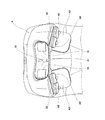
図1及び図2に示すように、枕部5には、その前面に被施療者の頭部、肩部、及び首部が沿うように構成された枕支持部51が形成されている。図2に示すように、この枕支持部51の左右内側には被施療者の首部を施療する首施療具としての左右一対の首エアセルA1(枕施療具)が配設されている。
As shown in FIGS. 1 and 2, the
各首エアセルA1には、クッション性の高いパッド10が設けられている。なお、本発明における枕施療具が施療する肩部には被施療者の首部を含む。また、枕部5の底部52には、被施療者の肩部を上方から施療する左右一対の肩上エアセルA2(肩上施療具;枕施療具)が配設されている。各肩上エアセルA2は、それぞれ独立して駆動する二個ずつのエアセルで構成されている。更に、枕部5の後部下側には、被施療者の肩部後側を施療する左右一対の肩下エアセルA3(肩部から背部へわたる肩下施療具;枕施療具)が配設されている。
Each neck air cell A1 is provided with a
また、図1に示すように腕カバー部材11の内側上部には、被施療者の肩部へ対応し、肩部近傍を側方向から施療する肩横施療具としての肩横エアセルA4が配設されている。上記の各エアセルは、いずれも枕部5や腕カバー部11に対して、移動不能に設けられているものである。腕カバー部材11の内側には、腕を掴む保持具60や腕の前部を施療する腕施療具61、座部1の両側には大腿部を施療する脚施療具62が配設されている。なお、エアセルの個数や配置は、この実施の形態に限定されるものではない。
Further, as shown in FIG. 1, a shoulder side air cell A4 as a shoulder side treatment device is disposed on the inner upper part of the
本実施形態に係るマッサージ機Mは、上記のように構成された揉み玉7及び各エアセルにより、被施療者の背部及び肩部を施療することができる。これにより、当該マッサージ機Mは、より効果の高い施療を被施療者に施すことができる。
The massage machine M according to the present embodiment can treat the back and shoulders of the user with the kneading
図1及び図3に示すように、枕部5の背面上縁には、背凭れ部3と同じ素材で覆われた布状の上エプロン12が設けられている。この上エプロン12は、枕部5の位置から背凭れ部3の上面を超して当該背凭れ部3の背面へわたっている。また、上エプロン12の先端には、左右方向に延びる錘13が固定されている。枕部5の背面下縁には、背凭れ部3と同じ素材で覆われた布状の下エプロン14が設けられている。この下エプロン14は、背凭れ部3の前面へ載せられ、被施療者が背凭れ部3に凭れかかると、当該被施療者と背凭れ部3との間に挟まれるようになっている。
As shown in FIGS. 1 and 3, a cloth-like
また、図3に示すように、背凭れ部3の上面には、上エプロン12を前後方向に挿通可能な挿通部31が設けられている。上エプロン12がこの挿通部31に挿通されると共に、その先端が錘13によって垂直方向に垂れ下がっている(図3参照)。これにより、枕部5が上方に付勢された状態となっている。
Moreover, as shown in FIG. 3, the
被施療者が、枕部5の位置を下げたいとき、被施療者は、枕部5や下エプロン14を保持し下方へ引っ張る。その際、被施療者は、枕部5を若干持ち上げ、背凭れ部3から枕部5を離間させた状態で斜めに引けば、より小さい力で枕部5を下げることができる。また、被施療者が背凭れ部3に凭れる際に、枕部5の背面下縁に設けられた下エプロン15が、被施療者と背凭れ部3との間に挟まれるので、任意の位置に下げた枕部5の位置を固定でき、ずれを防止することができる。
When the user wants to lower the position of the
枕部5の位置を上げたいとき、枕部5を浮かすなどし、固定又は保持状態から枕部5を開放させると、錘13の付勢により上方へ移動する。さらに、その際、被施療者は背凭れ部3の背面側に垂れ下がっている調整部材12や錘13を引っ張ってもよい。例えば、被施療者は錘13を斜めに持ち上げた状態で引っ張れば、より小さい力で枕部5を上げることができる。
When it is desired to raise the position of the
このように構成により、簡単な構成で枕部5を上下方向に位置調整自在とすることができる。また、枕部5の背面下縁に設けられた下エプロン14が、被施療者と背凭れ部3との間に挟まれるので、枕部5のずれを防止することができる。
With this configuration, the
図4及び図5は、枕部5からカバーや施療具等を取り除いた後の枕本体50を示している。枕本体50は、同図及び図6に示すように、左右方向に長いベース部16と、このベース部16にねじ止めされた前面部材17と、ベース部16の左右外側部において、凭れかかった被施療者の頭部(左右)方向へ進退自在とされた左右一対の揉み玉センサ部18(第二検知部)と、ベース部16の左右外側部において、凭れかかった被施療者の頭部方向へ進退自在とされたエアセルセンサ部19(第三検知部)とを備えている。
4 and 5 show the
各揉み玉センサ部18は、ベース部16の下部でくり抜かれた部分に合わさる略矩形状のプレート20と、このプレート20を進退自在とするバネ21と、当該プレート20の外側位置でベース部16に固定された第一リミットスイッチ22とを備えている。
枕部5が背凭れ部3に取り付けられた状態で、左右の各プレート20は上昇してきた揉み玉7が当たるところに位置する。第一リミットスイッチ22は接点部23を備え、プレート20の外側端には当該接点部23に当接する当接部24が設けられている。また、ベース部16には、各プレート20を背凭れ部3側へ付勢された状態で止める図示しない係止部が設けられている。
ベース部16に前面部材17が取り付けられると、上記プレート20は、バネ21によって背凭れ部3側へ付勢されかつ係止部で止められた状態となる。プレート20が背凭れ部側から揉み玉7に押されると、当該プレート20の当接部24が第一リミットスイッチ22の接点部23に当接し、当該第一リミットスイッチ22がこれを検知する。この信号が制御部9に送られる。つまり、第一リミットスイッチ22のオンオフが切り替わることにより、揉み玉7が枕位置にきたことが検知される。
Each kneading
In a state where the
When the
各エアセルセンサ部19は、ベース部16の両外側に位置する当接体25と、この当接体25の内側に位置する枠体26と、枠体26の内側に設けられたバネ27と、ベース部16に固定された第二リミットスイッチ28とを備えている。当接体25の内側には、左右方向に延びる筒状の大径部25aが形成されている。枠体26の外側に筒状の小径部26aが形成されている。これら大径部25aと小径部26aが、その間にバネ27を挟んだ状態で互いに嵌りあっている。
Each air
また、当接体25には、左右方向に延びかつ小径部26aの内周側に位置する柱状部(図示せず)が設けられている。当接体25は、ベース部16に対して外側へ付勢されかつ図示しない係止部で止められた状態となっている。第二リミットスイッチ28は、上記柱状部の内端面近傍に位置する接点部29を備えている。当接体25が外側から押されると、柱状部の内端面が第二リミットスイッチ28の接点部29に当接し、当該第二リミットスイッチ28がこれを検知する。この信号が制御部9に送られる。
Further, the
枕部5が背凭れ部3に取り付けられ、当該枕部5を上下方向に位置調整することで、腕カバー部11に配設された肩横エアセルA4が当該枕部5の側部に当接し得る。つまり、上記第二リミットスイッチ28のオンオフが切り替わることにより、腕カバー部11に配設された肩横エアセルA4が枕部5の側部に当接したことが検知される。
The
図7は、マッサージ機Mの制御系を示すブロック図である。制御部9は、座部1の下方に配置されていると共に(図1参照)、CPU,ROM,RAM,及び計時装置等から構成されており、各種の制御プログラムを実行し、接続された施療ユニットやエアセルの動作を制御することができる。制御部9には、給排気装置33が接続されており、当該給排気装置33の動作が制御される。
FIG. 7 is a block diagram showing a control system of the massage machine M. The control unit 9 is arranged below the seat unit 1 (see FIG. 1), and includes a CPU, a ROM, a RAM, a timing device, and the like, and executes various control programs and is connected to treatments. The operation of the unit and the air cell can be controlled. A supply /
給排気装置33は、電磁弁等の切替バルブ及びエアポンプ等によって構成されている。また、この給排気装置33は、首エアセルA1にエアホースで接続された制御弁60、肩上エアセルA2にエアホースで接続された制御弁61、肩下エアセルA3にエアホースで接続された制御弁62、及び肩横エアセルA4にエアホースで接続された制御弁63に、それぞれエアホースで接続されている。これにより、給排気装置33は、各エアセルに対して各々独立的に吸気及び排気を行うことが可能となっている。
The air supply /
また、制御部9には、駆動回路を介して揉み玉7に施療動作をさせる施療機構、及びバイブレータ機構等が接続されており、当該各機構を制御する。更に、制御部9には、肩位置センサ部、揉み玉センサ部18、及びエアセルセンサ部19が接続されており、これら各センサ部で検知した信号が当該制御部9に送られてくる。また、制御部9には、被施療者からの動作指示を受け付けるリモートコントローラ装置6が接続されており、被施療者はマッサージ機Mの動作を指示することができる。マッサージ機構や各エアセルを動作させる制御モードは複数用意されており、各種の施療モードやマニュアルモード等が実行されるようになっている。
The control unit 9 is connected to a treatment mechanism that causes the
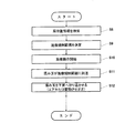
図8は、各種の施療モードやマニュアルモードにおいて、揉み玉7、首エアセルA1、肩上エアセルA2、肩下エアセルA3の施療動作の流れを示すフローチャートであり、図9は、マッサージ機Mに被施療者が着座した状態における、肩上エアセルA2及び肩下エアセルA3の位置と、揉み玉7の動きを示した模式図である。各モードがスタートすると、まず肩位置センサ部により被施療者の肩位置L1が検知される(ステップ1)。この肩位置L1とは、被施療者が座部1に着座し、枕部5を被施療者の肩部へあわせた際の肩位置と略同一である。この検知結果に基づいて制御部9により施療規制範囲35が設定される(ステップ2)。
FIG. 8 is a flowchart showing the flow of treatment operations of the kneading
施療規制範囲35とは、枕部5に配設された首エアセルA1、肩上エアセルA2及び肩下エアセルA3と、背凭れ部3に配設された揉み玉7とにより、被施療者の肩部への施療動作を択一的に実行させる範囲である。具体的には、肩下エアセルA3の上下寸法である約100mmが考慮され、施療規制範囲35は、肩下エアセルA3のさらに50mm下側である、肩位置L1から下側へ約150mmまで(L2)の範囲とされている。
The
施療動作が開始されると(ステップ3)、揉み玉7が下方から上昇し施療規制範囲35に到達する(ステップ4)。制御部9は、揉み玉7が施療規制範囲35に到達したのに対応して、首エアセルA1、肩上エアセルA2及び肩下エアセルA3を停止させる(ステップ5)。
When the treatment operation is started (step 3), the kneading
その際、揉み玉7の動きは変わらず、当該揉み玉7はそのまま上昇を続け、所定位置まで上昇しそこで折り返す。当該揉み玉7は、施療規制範囲35を上から下へ通過し、施療規制範囲35から離れる(ステップ6)。制御部9は、揉み玉7が施療規制範囲35から離れたことにより、首エアセルA1、肩上エアセルA2及び肩下エアセルA3の動作を復帰させる(ステップ7)。
At this time, the movement of the kneading
そして、揉み玉7が再度上昇してきて、施療規制範囲35に到達するのに対応して(ステップ4)、上記ステップ5〜ステップ7が繰り返される。
Then, in response to the kneading
つまり、制御部9は、揉み玉7が施療規制範囲35に存在するときは、首エアセルA1、肩上エアセルA2、肩下エアセルA3を停止し、揉み玉7が施療規制範囲35から離れたときは、当該首エアセルA1、肩上エアセルA2、肩下エアセルA3を復帰させる。
That is, the control unit 9 stops the neck air cell A1, the shoulder upper air cell A2, and the shoulder lower air cell A3 when the kneading
本実施形態によれば、背部を施療する揉み玉7(第一施療具)と、肩部及び首部を施療するエアセルA(第二施療具)とによる施療動作が、枕部の位置、即ち肩位置に応じて制御され、施療規制範囲35では肩部への施療動作が択一的に実行されるので、被施療者の肩部への負担を軽減することができる。
According to this embodiment, the treatment operation by the massaging ball 7 (first treatment device) for treating the back portion and the air cell A (second treatment device) for treating the shoulder portion and the neck portion is the position of the pillow portion, that is, the shoulder. Since the treatment is controlled according to the position and the treatment operation on the shoulder is selectively executed in the
また、被施療者が小柄な体型である場合、枕部5の位置調整が行われると、当該枕部5が腕カバー部11の内側上部に配設された肩横エアセルA4のところまで下がることがある。この状態で、肩横エアセルA4がそのまま動作し続けると、当該肩横エアセルA4は被施療者を施療せずに枕部5に干渉するだけとなる。この場合、肩横エアセルA4を動作させることが無駄となり、そのうえ枕部5と肩横エアセルA4との干渉音により、被施療者が不快感を受ける。
In addition, when the user is a small body, when the position of the
本実施形態のマッサージ機Mは、上述のように枕部5の側部にエアセルセンサ部19(第三検知部)を備え、このエアセルセンサ部19に肩横エアセルA4が接触することで、当該肩横エアセルA4が枕部5の側部に接触したことが検知される。その際、制御部9は、エアセルセンサ部19による検知結果に基づいて肩横エアセルA4の施療動作を停止する。これにより、肩横エアセルA4を動作させることが無駄とならず、枕部5と肩横エアセルA4とが干渉せず、被施療者に不快感を与えることが防止される。
図10及び図11は、マッサージ機Mの施療動作に関する第二実施形態を示す図である。本実施形態が上記第一実施形態と異なる点は、施療規制範囲35との関係から揉み玉7と各エアセルの施療動作を変更した点である。
The massage machine M of the present embodiment includes the air cell sensor unit 19 (third detection unit) on the side of the
10 and 11 are diagrams showing a second embodiment relating to the treatment operation of the massage machine M. FIG. This embodiment is different from the first embodiment in that the treatment operation of the kneading
各モードがスタートすると、まず肩位置センサ部により被施療者の肩位置が検知される(ステップ8)。この検知結果に基づいて制御部9により施療規制範囲35が決定される(ステップ9)。施療動作が開始されると(ステップ10)、揉み玉7が下方から上昇し施療規制範囲35に到達する(ステップ11)。制御部9は、揉み玉7が施療規制範囲35の下限L2に到達するのに対応して、当該揉み玉7を矢印36のように下方へ折り返させる(ステップ12)。
When each mode starts, the shoulder position of the user is first detected by the shoulder position sensor unit (step 8). Based on the detection result, the
これにより、揉み玉7は、施療規制範囲35へ侵入することができない。制御部9は、首エアセルA1、肩上エアセルA2及び肩下エアセルA3を施療動作させたままである。そして、揉み玉7が再度上昇してきて、施療規制範囲35に到達するのに対応して(ステップ11)、上記ステップ12が繰り返される。つまり、制御部9は、首エアセルA1、肩上エアセルA2及び肩下エアセルA3を常に動作させる一方で、揉み玉7を施療規制範囲35に侵入させない。
Thereby, the kneading
以上のように、背部を施療する揉み玉7(第一施療具)と、肩部及び首部を施療するエアセルA(第二施療具)とによる施療動作が、枕部5の位置、即ち肩位置L1に応じて制御され、施療規制範囲35では肩部への施療動作が択一的に実行されるので、被施療者の肩部への負担を軽減することができる。
As described above, the treatment operation by the massaging ball 7 (first treatment device) for treating the back portion and the air cell A (second treatment device) for treating the shoulder portion and the neck portion is the position of the
図12及び図13は、マッサージ機Mの施療動作に関する第三実施形態を示す図である。本実施形態が上記第一実施形態及び第二実施形態と異なる点は、被施療者の肩位置が変わり枕部5の位置調整が行われた場合、施療規制範囲35との関係から揉み玉7と各エアセルの施療動作を変更した点である。なお、図13では肩上エアセルA2のみを図示している。
12 and 13 are diagrams showing a third embodiment regarding the treatment operation of the massage machine M. FIG. This embodiment is different from the first embodiment and the second embodiment in that, when the shoulder position of the person to be treated is changed and the position of the
第一、第二実施形態と同様に、揉み玉7と肩部及び首部を施療する各エアセルとによる施療規制範囲35における施療動作が択一的に実行される。しかし、各モードが開始され当該施療規制範囲35が一旦設定された後において、背凭れ部3をリクライニングさせることや身体の位置をずらすことで肩位置が変わり、枕部3の位置を下げる場合がある。この場合、枕部5に配設された首エアセルA1、肩上エアセルA2及び肩下エアセルA3が、初期位置よりも下がってしまう。その際、制御部9は、枕部5に設けられた上記揉み玉センサ部18から送信されてくる信号を受けて、揉み玉7及び各エアセルを次のような手順で制御する。
Similarly to the first and second embodiments, the treatment operation in the
第一実施形態或いは第二実施形態のように肩位置L1から施療規制範囲35が一旦設定され施療動作が行われる。施療動作中に、被施療者により枕部5の位置が下げられる(ステップ13)。上昇する揉み玉7が枕部5の位置まで到達したことを、揉み玉センサ部18が検知する(ステップ14)。制御部9は、この検知結果に基づいて首エアセルA1、肩上エアセルA2及び肩下エアセルA3と揉み玉7を停止させる(ステップ15)。
As in the first embodiment or the second embodiment, the
これにより、枕部5の位置を下げた際、被施療者の肩部への負担を軽減することができる。また、揉み玉7の無駄な施療動作が防止され、揉み玉7が枕部5を押すことによる干渉音で被施療者に不快感を与えることが防止される。
Thereby, when the position of the
次に、制御部9は、施療規制範囲35を更新して新たな施療規制範囲40を設定する(ステップ16)。施療規制範囲40の設定に関して、揉み玉センサ部18の検知結果に基づき、枕部5が下げられた後の肩位置L3が算出され、新たな施療規制範囲40は、この肩位置L3から下側へ約150mmまで(L4)とされる。
Next, the control unit 9 updates the
それと同時に、制御部9は、矢印41のように揉み玉7を施療規制範囲40の下限L4の位置まで下降させる(ステップ17)。制御部9は、揉み玉7を施療規制範囲40外まで下降させた後、首エアセルA1、肩上エアセルA2及び肩下エアセルA3と揉み玉7の施療動作を復帰させる(ステップ18)。なお、制御部9は揉み玉7をL3まで下降させれば、この揉み玉7をそこから復帰させてもよい(各エアセルは停止状態)。その際、制御部9は、勿論、揉み玉7をL4まで下降させなければ、首エアセルA1、肩上エアセルA2及び肩下エアセルA3を復帰させることはできない。
At the same time, the control unit 9 lowers the massaging
これ以降、制御部9は、枕部5の位置調整を行う以前に設定された施療規制範囲35ではなく、新たな施療規制範囲40において揉み玉7と、首エアセルA1、肩上エアセルA2及び肩下エアセルA3とによる施療動作を択一的に実行させる。すなわち、当該新たな施療規制範囲40において、例えば上記第一実施形態におけるステップ4〜ステップ7を繰り返すか、上記第二実施形態におけるステップ11、ステップ12を繰り返せばよい。本実施形態によれば、枕部5の位置調整が行われても新たな施療規制範囲40が設定され、この新たな施療規制範囲40における揉み玉7と各エアセルとによる施療動作が択一的に実行されるので、被施療者の肩部への負担を確実に軽減することができる。
Thereafter, the control unit 9 does not use the
なお、上記で開示された実施形態はすべて例示であって制限的なものではない。例えば、第二施療具としてのエアセルを背凭れ部3の腰部や背部に配設してもよい。具体的には、腰部や背部における施療規制範囲を設定しておき、腰部や背部のエアセルが駆動している間は、揉み玉を当該施療規制範囲に侵入させないようにすればよい。或いは、揉み玉が同施療規制範囲に到達したときに腰部や背部のエアセルを停止させ、揉み玉はそのまま施療動作させてもよい。
Note that the embodiments disclosed above are all illustrative and not restrictive. For example, you may arrange | position the air cell as a 2nd treatment tool in the waist | hip | lumbar part of the
本発明は、例えば椅子型のマッサージ機に適用することができる。 The present invention can be applied to, for example, a chair-type massage machine.
1 座部
3 背凭れ部
5 枕部
7 揉み玉
9 制御部
50 枕本体
16 ベース部
18 揉み玉センサ部
22 第一リミットスイッチ
25 当接体
28 第二リミットスイッチ
35 施療規制範囲
40 新たな施療規制範囲
A1 首エアセル
A2 肩上エアセル
A3 肩下エアセル
A4 肩横エアセル
DESCRIPTION OF
Claims (11)
前記座部の後側に設けられた背凭れ部と、
前記背凭れ部の上部で上下方向に位置調整自在に設けられた枕部と、
前記背凭れ部に設けられて被施療者の背部を施療する昇降可能な第一施療具と、
前記座部に着座した被施療者の所定部位を施療すべく設けられた第二施療具と、
前記第一施療具及び前記第二施療具の施療動作を前記枕部の位置に応じて制御するように構成された制御部と、を備え、
前記第二施療具は、前記枕部に設けられた肩部から背部へわたる肩下施療具を有し、
前記制御部は、少なくとも前記肩下施療具の上下寸法を含む施療規制範囲を設定し、当該施療規制範囲における前記第一施療具及び前記肩下施療具による被施療者への施療動作を択一的に実行するよう構成されていることを特徴とするマッサージ機。 A seat where the user is seated;
A backrest provided on the rear side of the seat,
A pillow part provided to be adjustable in the vertical direction at the upper part of the backrest part;
A first treatment tool that can be raised and lowered to treat the back of the user provided in the backrest; and
A second treatment tool provided to treat a predetermined part of the user seated on the seat,
A control unit configured to control the treatment operation of the first treatment device and the second treatment device according to the position of the pillow portion , and
The second treatment device has a shoulder treatment device extending from the shoulder portion to the back portion provided in the pillow portion,
The control unit sets a treatment regulation range including at least the vertical dimension of the shoulder treatment device, and selects a treatment operation for the user by the first treatment device and the shoulder treatment device in the treatment regulation range. The massage machine is characterized in that it is configured to perform automatically.
前記制御部は、前記第三検知部による検知結果に基づいて当該肩横施療具の施療動作を停止する請求項10に記載のマッサージ機。 A third detection unit that detects that the shoulder side treatment device has contacted the side of the pillow unit;
The said control part is a massage machine of Claim 10 which stops the treatment operation | movement of the said shoulder lateral treatment tool based on the detection result by the said 3rd detection part.
Priority Applications (4)
| Application Number | Priority Date | Filing Date | Title |
|---|---|---|---|
| JP2007192360A JP5042737B2 (en) | 2007-07-24 | 2007-07-24 | Massage machine |
| PCT/JP2008/001858 WO2009013865A1 (en) | 2007-07-24 | 2008-07-10 | Chair type massage machine |
| CN200880100286.3A CN101778612B (en) | 2007-07-24 | 2008-07-10 | Chair type massage machine |
| US12/669,120 US20100198121A1 (en) | 2007-07-24 | 2008-07-10 | Chair-type massage machine |
Applications Claiming Priority (1)
| Application Number | Priority Date | Filing Date | Title |
|---|---|---|---|
| JP2007192360A JP5042737B2 (en) | 2007-07-24 | 2007-07-24 | Massage machine |
Publications (2)
| Publication Number | Publication Date |
|---|---|
| JP2009028089A JP2009028089A (en) | 2009-02-12 |
| JP5042737B2 true JP5042737B2 (en) | 2012-10-03 |
Family
ID=40399313
Family Applications (1)
| Application Number | Title | Priority Date | Filing Date |
|---|---|---|---|
| JP2007192360A Expired - Fee Related JP5042737B2 (en) | 2007-07-24 | 2007-07-24 | Massage machine |
Country Status (1)
| Country | Link |
|---|---|
| JP (1) | JP5042737B2 (en) |
Families Citing this family (2)
| Publication number | Priority date | Publication date | Assignee | Title |
|---|---|---|---|---|
| JP2010233920A (en) * | 2009-03-31 | 2010-10-21 | Panasonic Electric Works Co Ltd | Chair type massage machine |
| CN109125033B (en) * | 2018-09-12 | 2020-09-22 | 东阳市天齐知识产权运营有限公司 | Intelligent massage device |
Family Cites Families (5)
| Publication number | Priority date | Publication date | Assignee | Title |
|---|---|---|---|---|
| JP4171571B2 (en) * | 2000-05-31 | 2008-10-22 | ファミリー株式会社 | Massage machine |
| JP3992416B2 (en) * | 2000-03-01 | 2007-10-17 | ファミリー株式会社 | Massage machine |
| JP2001197991A (en) * | 2000-01-21 | 2001-07-24 | Fuji Iryoki:Kk | Pillow |
| JP2001224477A (en) * | 2000-02-17 | 2001-08-21 | Purotec Fuji:Kk | Pillow for massage |
| JP4615922B2 (en) * | 2004-07-16 | 2011-01-19 | 株式会社フジ医療器 | Massage machine |
-
2007
- 2007-07-24 JP JP2007192360A patent/JP5042737B2/en not_active Expired - Fee Related
Also Published As
| Publication number | Publication date |
|---|---|
| JP2009028089A (en) | 2009-02-12 |
Similar Documents
| Publication | Publication Date | Title |
|---|---|---|
| EP1884225B1 (en) | Massage apparatus in the form of a chair | |
| CN109069340B (en) | Sleep mode operation method in massage chair applying progressive muscle relaxation method and massage chair capable of performing the same | |
| US20100198121A1 (en) | Chair-type massage machine | |
| JP5078115B2 (en) | Chair massage machine | |
| JP2010148561A (en) | Chair type massage machine | |
| JP2017065504A (en) | Seat control apparatus and seat control method | |
| KR20180068091A (en) | A massage chair which is capable of user recognition using a heartbeat pattern and method for operating the same | |
| KR101056880B1 (en) | Heating and massaging chair and method of controlling the same | |
| JP2011010695A (en) | Massage chair | |
| JP4615922B2 (en) | Massage machine | |
| JP4684151B2 (en) | Massage machine | |
| JP5042737B2 (en) | Massage machine | |
| JP6100521B2 (en) | Massage machine | |
| JP2001104425A (en) | Massaging apparatus | |
| JP2000334017A (en) | Massage machine, relaxation apparatus and method for acquiring information | |
| JP4686084B2 (en) | Chair | |
| JP3956653B2 (en) | Massage machine | |
| JP5141433B2 (en) | Chair massage machine | |
| KR101779928B1 (en) | Unit chair for dental treatment including heat mat | |
| JP2010214155A (en) | Massage machine | |
| KR102189808B1 (en) | Method for operating a sleep mode in a massage chair using progressive muscular relaxation and the massage chair capable of using the same | |
| KR101645859B1 (en) | A chair for rectifing the spine | |
| JP2011000489A (en) | Massage machine | |
| JP4174125B2 (en) | Chair type massage structure | |
| JP2010131117A (en) | Massager |
Legal Events
| Date | Code | Title | Description |
|---|---|---|---|
| A621 | Written request for application examination |
Free format text: JAPANESE INTERMEDIATE CODE: A621 Effective date: 20100607 |
|
| A131 | Notification of reasons for refusal |
Free format text: JAPANESE INTERMEDIATE CODE: A131 Effective date: 20120424 |
|
| A521 | Written amendment |
Free format text: JAPANESE INTERMEDIATE CODE: A523 Effective date: 20120615 |
|
| RD05 | Notification of revocation of power of attorney |
Free format text: JAPANESE INTERMEDIATE CODE: A7425 Effective date: 20120615 |
|
| TRDD | Decision of grant or rejection written | ||
| A01 | Written decision to grant a patent or to grant a registration (utility model) |
Free format text: JAPANESE INTERMEDIATE CODE: A01 Effective date: 20120703 |
|
| A01 | Written decision to grant a patent or to grant a registration (utility model) |
Free format text: JAPANESE INTERMEDIATE CODE: A01 |
|
| A61 | First payment of annual fees (during grant procedure) |
Free format text: JAPANESE INTERMEDIATE CODE: A61 Effective date: 20120711 |
|
| R150 | Certificate of patent or registration of utility model |
Free format text: JAPANESE INTERMEDIATE CODE: R150 |
|
| FPAY | Renewal fee payment (event date is renewal date of database) |
Free format text: PAYMENT UNTIL: 20150720 Year of fee payment: 3 |
|
| FPAY | Renewal fee payment (event date is renewal date of database) |
Free format text: PAYMENT UNTIL: 20150720 Year of fee payment: 3 |
|
| S533 | Written request for registration of change of name |
Free format text: JAPANESE INTERMEDIATE CODE: R313533 |
|
| R350 | Written notification of registration of transfer |
Free format text: JAPANESE INTERMEDIATE CODE: R350 |
|
| R250 | Receipt of annual fees |
Free format text: JAPANESE INTERMEDIATE CODE: R250 |
|
| R250 | Receipt of annual fees |
Free format text: JAPANESE INTERMEDIATE CODE: R250 |
|
| R250 | Receipt of annual fees |
Free format text: JAPANESE INTERMEDIATE CODE: R250 |
|
| LAPS | Cancellation because of no payment of annual fees |